2510109651
movement to be imposed on the cone or on the friction sleeve is 0.5 times the diameter of the cone (see notę ^ para. 11).
10.5 Table of traditional penetrometer tips diverging from the Recommended Standard.
The penetrometer tips actually in use in several countries, and diverging from the Recommended Standard, are given below. They are indicated by a name, and a symbol which has been added to permit abbrevations when referring to them on the test graphs.
10.5.1 Mechanical penetrometer tip - notę 5 para. 11.
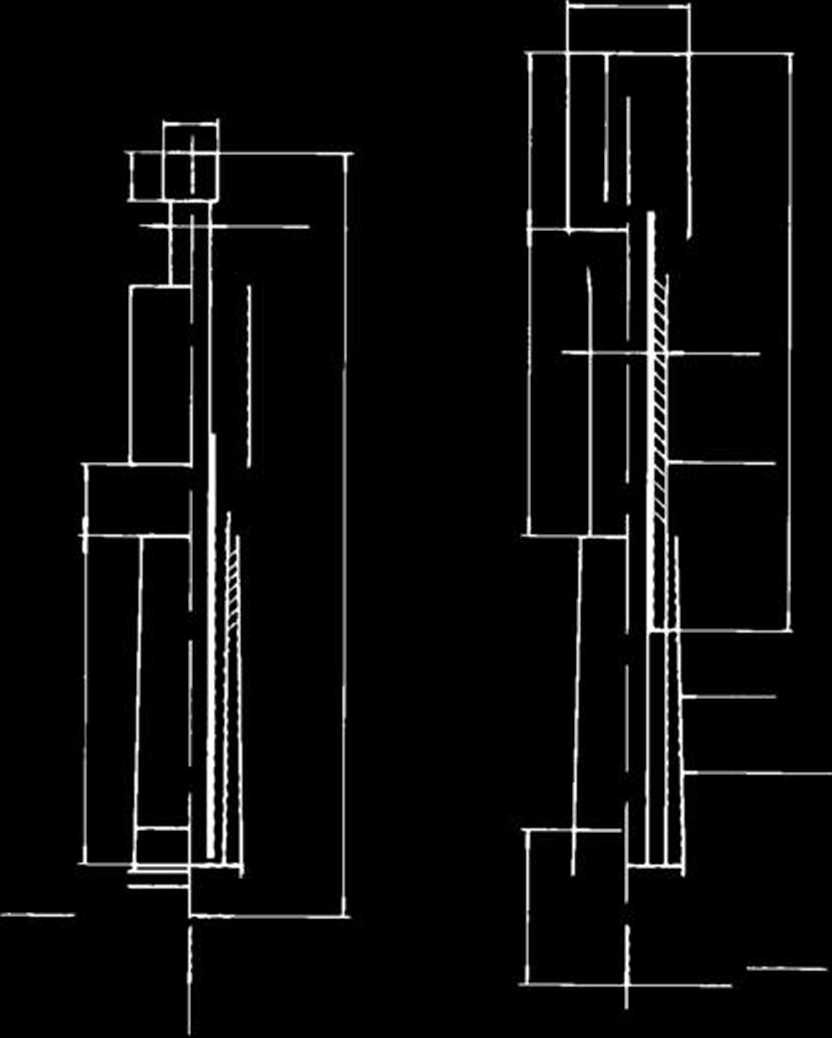
Ml The Dutch mantie cone penetrometer
tip (Fig. 5)
M2 The Dutch friction sleeve penetrom
eter tip (Fig. 6)
M3 The U.S.S.R. mantie cone penetrom
eter tip (Fig. 7)
M*ł The simple cone penetrometer tip
(Fig. 8)
M5•1 The Andina cone penetrometer tip (Fig. 9a)
M5.2 The Andina friction sleeve cone penetrometer tip (Fig. 9b)
10.5.2 Electric cone penetrometer tip.
El.l The Delft electric penetrometer tip (Fig. lOa)
El.2 The Delft friction sleeve electric penetrometer tip (Fig. lOb)
E2 The Degebo friction sleeve electric
penetrometer tip (Fig. 11)
10.5-3 Hydraulic penetrometer tip.
Hl.l The Parez hydraulic penetrometer tip (Fig. 12a)
HI.2 The Parez friction sleeve hydraulic penetrometer tip (Fig. 12b)
10.6 Precision of the measurements.

Fig. 5 The Dutch mantie cone penetrometer tip. Symbol: Ml.
10.7 Static dynamie penetrometers and pre-boring cone penetrometers.
Penetration can be inereased by the use of static dynamie penetrometers and also by the use of penetrometers eąuipped with preboring tools.
It must be clearly indicated in the report and on the test graphs when such eąuipment has been used.
When testing diverges from the Recommended Standard two classes of precision are de-fined:
the normal precision class: see section 5
the lower precision class: the pre-
cison obtained should not be worse than the larger of the following values:
10? of the measured value 2% of the maximum value of the rangę
In all such cases the class of precision of the tests shall be indicated in the report and on the test graphs.
10.8 Precautions, checks and verifications.
10.8.1 Mechanical penetrometers.
10.8.1.1 Push-rods.
There should not be any protruding edge on the inside of the push-rods at the screw connection between the rods (Fig. 13).
10.8.1.2 Inner rods.
The diameter of the inner rods shall be 0.5 to 1 mm less than the internal diameter of the push-rods. The inner rods must slide very easily through the push-rods.
The ends of the inner rods should be exactly at right angles to the axis of the rod and be machine-tooled to a smooth surface.
106
Wyszukiwarka
Podobne podstrony:
fuli vertical loads, like in normal foundations or underpinning. On the other hand, it is to be
image002 AGENT WITHOUT PORTFOLIO When the fifth man to be landed on the English coast from a German
MR293R190?3 1 PREPARAT!ON AND PAISTING MKTHOD HO REPAIRS POSSIBLE Ali fittings to be painted in the
47267 MR293R190?3 1 PREPARAT!ON AND PAISTING MKTHOD HO REPAIRS POSSIBLE Ali fittings to be painted i
Joe Weider new and org charts 2 1 THE WEIDER SYSTEM OFTHIRD COURSE CHART No. 3 BEGINNER‘S EXERCISES:
tmta!7 Women s beits are less often seen on contemporary illustrations. They were morę Iikely t
MR293R190?3 1 PREPARAT!ON AND PAISTING MKTHOD HO REPAIRS POSSIBLE Ali fittings to be painted in the
Annexure 6 NEFT FORM FOR PERSONAL ACCIDENT INSURANCE (To be submitted by the claimant only) The Clai
morphogenetical maps to be eliminated from the category of the detailed geomor-phological map. 8.
" Better to be slapped with the truth than kissed with a
14 I believe both thc Gyrinini and the Orecłochilini to be while I regard the Enhydrini as an certai
więcej podobnych podstron