372596173
158
RIKEN Accel. Próg. Rep. 24 (1990)
V-2-ll. Bump Magnet of SPring-8
H. Miyade, H. Takebe, and S. Motonaga
On injection of a beam, a bump orbit is formed around the injection section; the orbit is parallel to the reference orbit and has an amplitudę of 13.34 mm. The bump orbit is formed by four bump mag-nets installed at the positions shown in Fig.l. Two of the four are installed in the both ends of the injection section (BP2, BP3) and the other two are beside bending magnets (BPI, BP4).
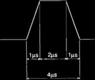
The magnets are excited in two operation pat-tems shown in Fig. 2. In a 1-Hz modę the magnets are energized once a second, and in a 60-Hz modę 8 times a second with repetitions of 60 Hz. Fach pulse has a trapezoid form with a 4 /xs in width, a 1 /xs rise time, and a 2 /xs fiat top.
To reduce an eddy current, the magnet core is madę of ferrite and the vacuum chamber is madę of ceramic.
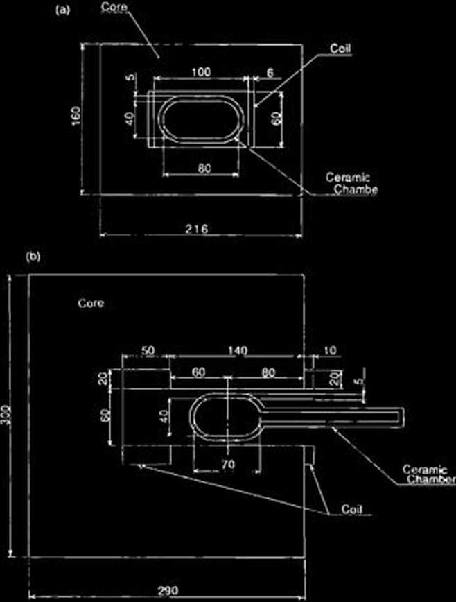
Cross sectional views and main parameters of
Operation Panem


Fig. 1. Arrangement of bump magnets. BP, Bump Magnet; BM, Bending Magnet; Q, Quadrupole Magnet; S. Sextupole Magnet; SEP, Septum Magnet; AB, Absorber; CR, Crotch.
i Hz MODĘ
|
1 c | |||
GO Hz MODĘ
t ?3 8 t?3 a i>3 ®
|
M | ||||||
|
.16 |
7ms |
—\c * | ||||
|
is | ||||||
Current Wave Form

Fig. 2. Operation pattem and current wave fonn of bump magnets.

Fig. 3. Cross sectional views of bump magnets. (a), BPi. BP2, BP3; (b), BP4.
Wyszukiwarka
Podobne podstrony:
92 RIKEN Accel. Próg. Rep. 24 (1990)111-5. Instrumentation1. Design of a Microbeamline for a Compact
103 RIKEN Accel. Próg. Rep. 24 (1990)111-5-9. Test Experiment of the GARIS/IGISOL K. Morita, T. Nomu
116 RIKEN Accel. Próg. Rep. 24 (1990)111-5-19. Responses of Large Position-Sensitive Detectorsto Hea
174 RIKEN Accel. Próg. Rep. 24 (1990)V-2-20. Performance Test of Lumped NEG PumpS.R. In,1 T. Maruyam
199 RIKEN Accel. Próg. Rep. 24 (1990)V-2-34. Bending Fabrication of a Vaccum ChamberT. Nishodono, T.
11 RIKEN Accel. Próg. Rep. 24 (1990)111-1-2. Three a Disintegration of 12C in the Field of208Pb Nucl
63 RIKEN Accel. Próg. Rep. 24 (1990)111-2-28. Development of Nuclear Track Microfilters N. Nakanishi
72 RIKEN Accel. Próg. Rep. 24 (1990)111*3-8. Dry Separation of Radioactive Nuclides from a Gold Targ
80 RIKEN Accel. Próg. Rep. 24 (1990)111-3-16. Development of an lon Beam Sputtering Method toPrepare
174 RIKEN Accel. Próg. Rep. 24 (1990)V-2-20. Performance Test of Lumped NEG PumpS.R. In,1 T. Maruyam
63 RIKEN Accel. Próg. Rep. 24 (1990)111-2-28. Development of Nuclear Track Microfilters N. Nakanishi
więcej podobnych podstron