372596176
160
RIKEN Accel. Próg. Rep. 24 (1990)
V-2-12. Measurement of a 508 MHz Model Coupler for
the SPring-8 Storage Ring
K. Inoue, Y. Kawashima, T. Nakamura, and M. Hara

RF
NETWORK
ANALYZER
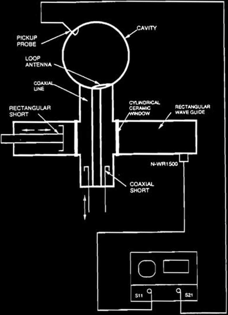
Fig. 2. Schematic cross section of the model coupler.
In the SPring-8 storage ring, eight 508.58 MHz cavities are located in each of four 6.5-m straight sections with low-betatron functions. The RF" power generated by a CW klystron is fed to the eight single-cell cavities through input couplers. Thus a total of 32 couplers are needed during operation.
The input coupler consists of an adaptor from a waveguide to a coaxial linę, an RF window for vacuum seal, and a loop antenna. We decided following design policies of the input couplers for the SPring-8 storage ring.
(1) A total of voltage standing wave ratio is within 1.05.
(2) A multipactoring discharge on the RF window is reduced as Iow as possible.
i
Fig. 1. Photograph of the model coupler.
According to these policies, we have fabricated a model coupler shown in Fig. 1 to study its RF' characteristics. A schematic cross section of the model coupler is shown in Fig. 2. It includes a WR1500 rectangular waveguide, an adaptor from the waveguide to a WX152D coaxial linę, a cylindrical RF window, and a loop antenna. We have adopted a cylindrical RF window, 152 mm in diameter, 193 mm long, 5 mm thick, madę of 95% alumina ceramics, which is successfully used for KEK TRISTAN APS cavities operating at 508 MHz,ł) and located it at the transition from the waveguide to the coaxial linę. The end plates of the rectangular waveguide and the coaxial linę are movable. The direction of the loop antenna was adjusted by rotating the coax-ial linę. RF" characteristics were measured by a
S\l I09 MAC S^i log MAC
REF -10.0 dB REF -10.0 dB
10.0 dB/ 10.0 dB/

CENTER 0.509500000 GHi SPAN 0.005000000 GMi
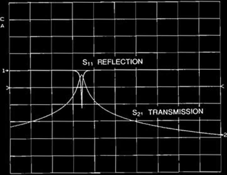
Fig. 3. Measured resonance of the 508 MHz model cavity.
reflection and transmission method with a net-work analyzer. F"igure 3 shows a preliminary result of the resonance characteristics of the model cavity2) when the model coupler is
Wyszukiwarka
Podobne podstrony:
94 RIKEN Accel. Próg. Rep. 24 (1990)111-5-2. Design of a Decay Muon Channel Using an Axially Symmetr
102 RIKEN Accel Próg. Rep. 24 (1990)111-5-8. Performance of Isotopic Separation in RIPS T.Nakamura,
RIKEN Accel. Próg. Rep. 24 (1990)V-2-30. Manufacture of a Complicated Ceramic Chamber and Its Joinin
193 RIKEN Accel. Próg. Rep. 24 (1990)V-2-31. Mounting of a Straight Section Vacuum Chamberwith Slide
108 RIKEN Accel. Próg. Rep. 24 (1990)111-5-12. Status Report of the RIKEN Swinger-Magnetic Analyzer
12 RIKEN Accel. Próg. Rep. 24 (1990)111-1-3. Coulomb Breakup Reaction of 90 MeV/u 140 T. Takei, T. M
12 RIKEN Accel. Próg. Rep. 24 (1990)111-1-3. Coulomb Breakup Reaction of 90 MeV/u 140 T. Takei, T. M
92 RIKEN Accel. Próg. Rep. 24 (1990)111-5. Instrumentation1. Design of a Microbeamline for a Compact
103 RIKEN Accel. Próg. Rep. 24 (1990)111-5-9. Test Experiment of the GARIS/IGISOL K. Morita, T. Nomu
105 RIKEN Accel. Próg. Rep. 24 (1990)111-5-10. Velocity Distribution of IGISOL lon Beams M. Koizumi,
110 RIKEN Accel. Próg. Rep. 24 (1990)111-5-14. Test for Dispersive-Mode Beam Transportto the SMART
116 RIKEN Accel. Próg. Rep. 24 (1990)111-5-19. Responses of Large Position-Sensitive Detectorsto Hea
121 RIKEN Accel. Próg. Rep. 24 (1990)IM-5-23. A Test for SMART Neutron Detectors H. Orihara, K. Hata
więcej podobnych podstron