372596186
RIKEN Accel. Próg. Rep. 24 (1990)
V-2-30. Manufacture of a Complicated Ceramic Chamber and Its Joining
Methods to an Aluminum-alloy Chamber
T. Nishidono, S. Yokouchi, H. Daibo, T. Toga,* and S.H. Be
o
V
wiih hydrostaic prcss. at- ImO r
Ni clectroplaiing after Ho Hn letali/ing 10 im. ai 830 --8S0 X: in vacuui fumace. TIG welding
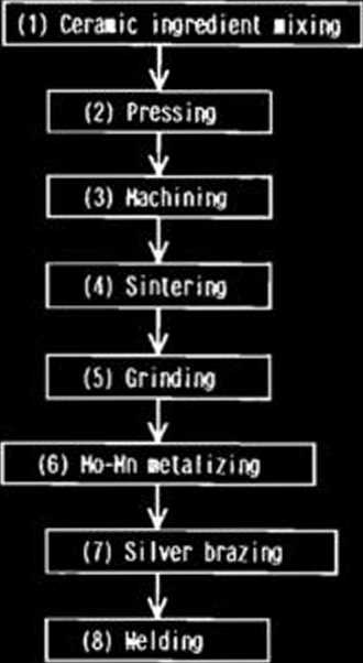
Fig. 2. Fabrication process of a ceramic chamber.
Mo-Mn ( 10 -20 pm ) j_ Metalliziog
Alumina ceramics \
U/ !
We are considering to use alumina ceramic chambers to prevent eddy current generating on the surface of the chamber used in fast bump magnets.0 Since the materiał of normal vacuum chambers in SPring-8 is aluminum-alloy, joining of ceramics to aluminum metals is required.
(a)
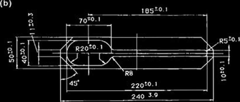
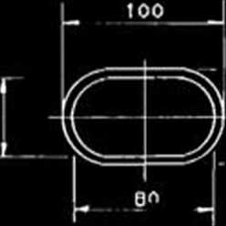
Fig. 1. Cross-sectional view of ceramic chambers. (a) for No. 1, No. 2, and No. 3 bump magnet. No. 2 and No. 3 are 200 mm in length; No. 1 is 300 mm in length. (b) for No. 4 bump magnet, 350 mm in length.
The cross-sectional views of two different ceramic chambers designed for SPring-8 are shown in Fig. 1. A ceramic chamber of a simple geometry as shown in Fig. 1 (a) can be manufactured easily, and direct joining of ceramics to aluminum (Al)-alloy is feasible by using an existing techniąue. However the manufacture of a complicated chamber of 35 cm in length and 26 cm in width as shown in Fig. 1 (b) is difficult, and the joining of this chamber to Al-alloy one is not easy either. Therefore its manufacture technique is reąuired to be estab-lished.
A manufacture process of the ceramic chamber is shown in Fig. 2. An important subject in the process is to improve a manufacture accu-racy. A particular attention is paid to the joining method because the joint must be stronger and leak-tight. For the complicated ceramic chamber, direct joining to stainless-steal (SUS) or
2
4
6
7
8
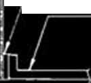
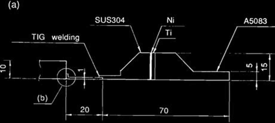
Al-alloy is impossible because of thermal stress caused by large thermal expansion mismatch between the two. A joining process of ceramics to Al-alloy is shown in Fig. 3. To minimize the stress in the seal or ceramics, SUS of a different expansion coefficient can be jointed with a grad-ed seal.
The seal consists of Fe-Ni-Co alloy (KOVAR) segment, which have a slightly different expan-sion and forms a zonę of gradual transition with

Ni ( 2 - 5 pm ) : Electroplating Ag ( - 100 pm ) : Brazing
Fe-Ni-Co Alloy ( KOVAR )
Fig. 3. (a) Geometry of a transition piece; (b) detail of the joining area of a KOYAR piece.
*
KYOCERA Corporation.
Wyszukiwarka
Podobne podstrony:
94 RIKEN Accel. Próg. Rep. 24 (1990)111-5-2. Design of a Decay Muon Channel Using an Axially Symmetr
102 RIKEN Accel Próg. Rep. 24 (1990)111-5-8. Performance of Isotopic Separation in RIPS T.Nakamura,
160 RIKEN Accel. Próg. Rep. 24 (1990)V-2-12. Measurement of a 508 MHz Model Coupler forthe SPring-8
193 RIKEN Accel. Próg. Rep. 24 (1990)V-2-31. Mounting of a Straight Section Vacuum Chamberwith Slide
92 RIKEN Accel. Próg. Rep. 24 (1990)111-5. Instrumentation1. Design of a Microbeamline for a Compact
103 RIKEN Accel. Próg. Rep. 24 (1990)111-5-9. Test Experiment of the GARIS/IGISOL K. Morita, T. Nomu
105 RIKEN Accel. Próg. Rep. 24 (1990)111-5-10. Velocity Distribution of IGISOL lon Beams M. Koizumi,
108 RIKEN Accel. Próg. Rep. 24 (1990)111-5-12. Status Report of the RIKEN Swinger-Magnetic Analyzer
110 RIKEN Accel. Próg. Rep. 24 (1990)111-5-14. Test for Dispersive-Mode Beam Transportto the SMART
116 RIKEN Accel. Próg. Rep. 24 (1990)111-5-19. Responses of Large Position-Sensitive Detectorsto Hea
121 RIKEN Accel. Próg. Rep. 24 (1990)IM-5-23. A Test for SMART Neutron Detectors H. Orihara, K. Hata
RIKEN Accel. Próg. Rep. 24 (1990)111-5-25. High Speed Serial Data Link for PC-9801 J. Fujita > PC
129 RIKEN Accel. Próg. Rep. 24 (1990)IV-2. Cross Section Data for 68Ge ProductionY. Tendow, A. Hashi
132 RIKEN Accel. Próg. Rep. 24 (1990)IV-5. Cross Sections Calculated by an ALICE Codęin the A = 50 —
więcej podobnych podstron