372596184
186 S. Takahashi et ai
(D For the beam chamber side Q,/2 = h x A x AT
Q i : reąuired power for bakeout (W)
Q2 : heat generated during NEG activation (W)
v : water velocity (cm/s)
N : number of cooling channels (—)
p : density (at 150°C) = 0.916 kg/cnri
k : conversion factor = 4.33 J/gK
A : heat transfer area (cm2)
h : heat transfer coefficient (W/cm2-°C)
= 0.023 (Re)0 S(Pr)0 4 x )Jd AT: temperaturę differrence between heated water and channel’s wali of a chamber (°C) A : thermal conductivity (at 150°C)
= 0.587 kcal/m-hr-°C Pr : Plandtl number (at 150°C) = 1.15
The calculations give 7'1 = 141.6°C and T;J=145.3°C for y = 1.5 m/s and T'2 = 150°C (see Fig. 2). As a result, AT’s for the pumping and beam chamber side are 0.30°C and 1.59°C, respectively. This means that the temperaturę of the chamber wali is almost the same as that of heated water. Thus the maximum thermal gradients of the chamber for the longitudinal direction and the transverse direction are 8.4°C/30m and 3.7°C, respectively. A total pressure loss for a system of one celi is about 1.01 kg/cm2, and a reąuired flow is approximately 1000 Uh.
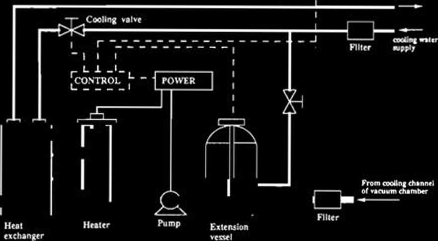
Figurę 3 shows a rough layout of a unit of HBS. At first, sińce the vapor pressure of water at 150°C
Thcrmo cou^ 'Tl Ta cooiing
- ■ of rftaram chimbfr

Fig. 3. Diagram of the Heated Water Bakeout System.
is about 5.9 kg/cm2-G, the hydraulic pressure of hot water should be increased up to about 7 kg/ cm2-G. After that, to increase the temperaturę up to about 150°C, the water is transferred to the heater by a pump. A heat exchanger is used when the heater is overheated or in case of emergency. The heater power and the cooling valve will be adjusted to keep the temperaturę T, at a predeter-mined value.
We are planning to test and evaluate the performance of HBS, using a 5 m prototype straight chamber (Fig. 1).
References
1) H. Sakamoto, T. Bizen, S. Yokouchi, Y. Morimoto, T. Nishidono, Y.P. Lee, and S.H. Be: RIKEN Accel. Próg. Rep.. 23, 145 (1989).
Wyszukiwarka
Podobne podstrony:
scan0024 6 Sign up for the FREE LeisureArts E-newsłetter at www.leisurearts.com to receive free proj
33. Thick Membranę Solid Contact ISE for the Detection of Lead at Picomolar Levels
ANNA sum09 USA50 on the sunny sideStart your daywith a well-balancedmeal and a feast for the senses
182 S. Takahashi et al. at the location of AB1 for thermal load tests we did a beam dynamical
00196 ?c3e9ff6e1645b5c66f96f0e3b703fa 198 Messina, Montgomery, Keats & Runger The residual for
et al. (1980) for the stability analysis of Palazzo della Ragione, a 13t h Century building in Milan
CQS04 4r (b) Torches with clip attachments for the weapons concemed: the beam of t
132 _. Talatbek Masadykov et James Michael Page, « Negotiating with the Taliban: Toward a Solution f
528 M. Daszykowski et ai To interpret differences among the groups of sagę samples, score and loadin
186 M. Sajewicz et al.Vapour Distilladon in the Deryng Apparatus Dried plant materiał (50 g) from th
19958 w25$ ABOVE ‘Siena’s Chamberlain and clerk at work on the cover of the Biccherna records
151 Kempermann, G. et Gage, F. H. (1999). New nerve cells for the adult brain. Scientific american-a
62 Dawson, W. A. (1960). Home-made counting chambers for the irwerted microscope. Limnology and ocea
więcej podobnych podstron