7696081859
12 Diagnostyka - Applied Structural Health, Usage and Condition Monitoring' 3(63)/2012 CISZEWSKI, BURATOWSKI, GIERGIEL, KURC, MAŁKA, The Pipes Mobile Inspection Robots
|
When slip is neglected: | |
|
1- ‘j * |
(8) |
|
Velocity components of the point C: | |
|
ie= Ycsosfi. |
(9) |
|
Se = Ycsfnj3, |
(10) |
After taking into account the relation (7) the eąuation of siinple kineinatic task was obtained:
|
róŁU - 4 rcfjU -xe =---cos3, |
(U) |
|
rtł. U — s.} + rrf.U - s*) *i 2 |
(12) |
|
, rdjU - - rt?ŁU — ffj} ' R |
(13) |

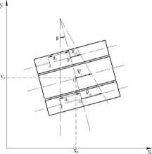
Fig. 5. Diagram of the robot frame tum for the angle
3. DYNAMICS OF THE INSPECTION ROBOT
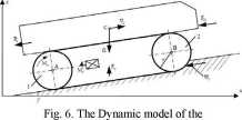
In the dynamie model of the robot, the kinematic description is expanded, but still considering tire same characteristic points on tlie structure (Fig. 6).
The dynamie description of the robot [1, 2, 3, 6, 15, 17] is based on energetic method based on Lagrange equations. In order to avoid modeling problems connected with decoupling Lagrange multipliers, Maggi eąuations were used. The finał form of the dynamie motion eąuations based on Maggi fonnalisin have been presented as follows:
(jlfliCl - ffi.) ff*)] cos 7) (ro* 4-
2m) jrCl - Sf) cos y +
-ffj.)4- “ff*)]siny)4-
2m) - s^atny + IfttL =
Bfaiftl 4- C"Qi5Ą - Q.5f^ - 0,5<?sfii^ 4-
tK5Ą- sta7- Q.3ffa)r(l -ą?,
4- cos 7) 4-
2m)-r(l — sj) cos y 4-(jtfliU - 4- siny) (m% 4-
2 wt) jtCI - s-j) sm/ 4- /_£«! =
4- C-&5Ą. - 0.51^, - O.Sffstny 4-0,SĄ. 3(117- O.SłYn>(l -ą),
where: «i - angle of rotation of wheel 1 , a2 - angle of rotation of wheel 2, mR - frame mass, m - track mass, Wt - the force of resistance of the rolling track. Pu - pulling force, Fw - hydrostatic force, FD -hydrostatic resistance force, Iy - inertia moment for tire robot frame, sŁ - slip for wheel 1, s2 - slip for wheel 2, G - gravity force, q - efficiency.

robot
The dynamie motion eąuations correspond to the robot moving on the horizontal surface. In case of operation with other track aligmnents, it is necessary to take into consideration the projections of forces and moments acting on a particular track.
4. OPERATION ENVIRONMENTS
According to project reąuirements, the robot is capable of positioning its driving mechanism in various ways, to accommodate to working enviromnent. For the most compact aligmnent. the robot will be able to operate in pipes with diameter above 210 mm (Fig. 7. a). In the Fig. 7. b), we may observe the robot with aligmnent for operation in a 330 mm diameter pipę. The upper limit of pipę
Wyszukiwarka
Podobne podstrony:
10 Diagnostyka - Applied Structural Health, Usage and Condition Monitoring’ 3(63)/2012 CISZEWSKI, BU
14 Diagnostyka - Applied Structural Health, Usage and Condition Monitoring 3(63)/2012 CISZEWSKI, BU
Diagnostyka - Applied Structural Health, Usage and Condition Monitoring’ 3(63)/2012 Cholewa, Amarowi
Diagnostyka - Applied Structural Health, Usage and Condition Monitoring’ 3(63)/2012
Diagnostyka - Applied Structural Health, Usage and Condition Monitoring’ 3(63)/2012
Diagnostyka - Applied Structural Health, Usage and Condition Monitoring 3(63)/2012
Diagnostyka - Applied Structural Health, Usage and Condition Monitoring’ 3(63)/2012
Diagnostyka - Applied Structural Health, Usage and Condition Monitoring 3(63)/2012
Diagnostyka - Applied Structural Health, Usage and Condition Monitoring 3(63)/2012 Spis treści /
Diagnostyka - Applied Structural Health, Usage and Condition Monitoring 3(63)/2012 Cholewa, Amarowi
Diagnostyka - Applied Structural Health, Usage and Condition Monitoring 3(63)/2012 Cholewa, Amarowi
Diagnostyka - Applied Structural Health, Usage and Condition Monitoring 3(63)/2012 Cholewa, Amarowi
Diagnostyka - Applied Structural Health, Usage and Condition Monitoring 3(63)/2012 Cholewa, Amarowi
Diagnostyka - Applied Structural Health, Usage and Condition Monitoring’ 3(63)/2012 Cholewa, Amarowi
18 Diagnostyka - Applied Structural Health, Usage and Condition Monitoring 2(62)/2012 Charchalis, D
DSC00578 (4) rOIKTS .. 12. What tMMl are used in 1** and 2"* conditional? When is it useri? Glv
8 Diagnostyka - Diagnostics and Structural Health Monitoring l(57)/2011 GONTARZ,
Diagnostyka - Diagnostics and Structural Health Monitoring l(57)/2011 9 GONTARZ,
więcej podobnych podstron