7696081860
Diagnostyka - Applied Structural Health, Usage and Condition Monitoring' 3(63)/2012 13
CISZEWSKI, BURATOWSKI, GIERGIEL, KURC, MALKA, The Pipes Mobile Inspection Robots

diameter is detennined by the capabilities of the vision system.
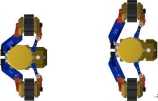
For pipes and ducts with rectangular cross-section, there are two different configurations. The first one, presented in the Fig. 8. a) is the configuration, when tracks are horizontally aligned, giving the robot the highest stability and lowest height, whereas in the Fig. 8. b) tracks positioned the closest to each other are depicted. making the robot capable of operation in narrower and higher ducts, or positioning the camera higher above the ground for greater field of view.
a) b)
Fig. 7. Operation in round pipes: a) ©206 mm, b) ©330 mm

a) b)
Fig. 8. Operation in rectangular ducts:
a) wide,
b) narrow

a) b)
Fig. 9. Track parallel extension:
a) ininimum,
b) maximum
Parallel extension of tracks is also possible for the robot structure. It may be utilized to operate in pipes or ducts with rectangular or circular cross section tliat are oriented in any direction, basing on friction force with respect to the walls. Possible minimum and maximum extensions (230 imn to 270 mm) are presented in Fig. 9.
5. TESTING OF INUKTUN MICROTRACS IN
REAL ENVIRONMENT
In case of motion of such mobile platforms as the described robot, there appear problems with precise determination of position and orientation due to defonnations of track treads and working surface. In order to reduce this unwanted influence, a previously described mathematical model was proposed. In the model it was assumed that that the track treads deform and the surface is undefonnable.
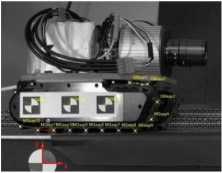
The testing procedurę was conducted in a laboratory with usage of horizontal pneumatic table with vibration isolation, Phantom v9.1 camera with 2 megapixel resolutioa The vision system was eąuipped with TEMA Automotive software, dedicated to motion analysis, that feature automatic tracking and processing tools. The object of investigation consisted of two Inuktun Microtrac units mounted to a test frame with dimensions and weight corresponding to designed robot. Markers were placed on each track tread and on the track body. During motion, displacements in axes x and y were obtained for particular treads with respect to the marker situated in the lower left comer of the table (Fig. 10). In the we may obsen e plots of tread marker position in Y axis. Basing on the region of plot when the investigated tread is in contact with the table (lower plot), deformation tliat will be introduced in the was calculated to be M = 0.02 mm for this kind of motion.

Fig. 10. Track deformation test -markers
Wyszukiwarka
Podobne podstrony:
Diagnostyka - Applied Structural Health, Usage and Condition Monitoring’ 3(63)/2012 Cholewa, Amarowi
Diagnostyka - Applied Structural Health, Usage and Condition Monitoring’ 3(63)/2012
10 Diagnostyka - Applied Structural Health, Usage and Condition Monitoring’ 3(63)/2012 CISZEWSKI, BU
Diagnostyka - Applied Structural Health, Usage and Condition Monitoring’ 3(63)/2012
12 Diagnostyka - Applied Structural Health, Usage and Condition Monitoring 3(63)/2012 CISZEWSKI, BU
14 Diagnostyka - Applied Structural Health, Usage and Condition Monitoring 3(63)/2012 CISZEWSKI, BU
Diagnostyka - Applied Structural Health, Usage and Condition Monitoring’ 3(63)/2012
Diagnostyka - Applied Structural Health, Usage and Condition Monitoring 3(63)/2012
Diagnostyka - Applied Structural Health, Usage and Condition Monitoring 3(63)/2012 Spis treści /
Diagnostyka - Applied Structural Health, Usage and Condition Monitoring 3(63)/2012 Cholewa, Amarowi
Diagnostyka - Applied Structural Health, Usage and Condition Monitoring 3(63)/2012 Cholewa, Amarowi
Diagnostyka - Applied Structural Health, Usage and Condition Monitoring 3(63)/2012 Cholewa, Amarowi
Diagnostyka - Applied Structural Health, Usage and Condition Monitoring 3(63)/2012 Cholewa, Amarowi
Diagnostyka - Applied Structural Health, Usage and Condition Monitoring’ 3(63)/2012 Cholewa, Amarowi
18 Diagnostyka - Applied Structural Health, Usage and Condition Monitoring 2(62)/2012 Charchalis, D
8 Diagnostyka - Diagnostics and Structural Health Monitoring l(57)/2011 GONTARZ,
Diagnostyka - Diagnostics and Structural Health Monitoring l(57)/2011 9 GONTARZ,
10 Diagnostyka - Diagnostics and Structural Health Monitoring 1(57)/2011 GONTARZ,
Diagnostyka - Diagnostics and Structural Health Monitoring l(57)/2011 11 GONTARZ,
więcej podobnych podstron