8589356914
Volume XLI THE SHORT WAVE MAGAZ1NE 363
Volume XLI THE SHORT WAVE MAGAZ1NE 363
from the metalwork. The input Socket is connected by coax to the transmitter pi-tank output. Metalwork is tied to terminal łE* and this point may be connected to either the station earth or a counterpoise. The cabinet is mounted on insulating feet and may be left on top of the transmitter if this is a convenient position.
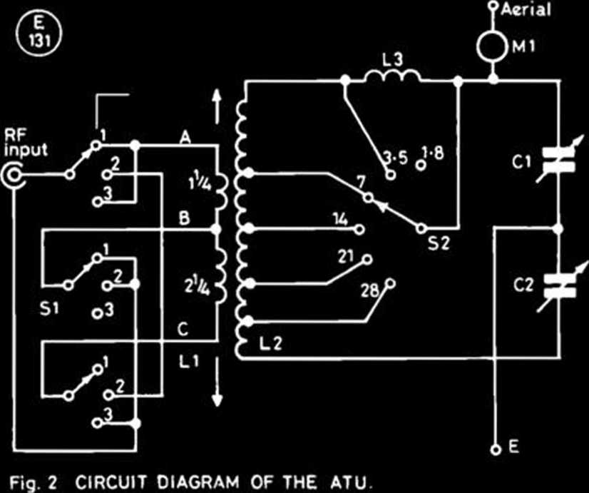
The three-pole, three-way switch, SI, permits three sizes of link, as follows: position 1, 1 V* turns; position 2, VA tums; position 3, V/i turns. The switching may appear unduly complicated, but was devised so that three link sizes are obtained using just three connections, the unused section is not short-circuited, and the unused section is connected to the earthy end of the section in use. Three leads A, B, and C connecting the switch to LI form the rigid support for the link, the arrows indicating that the link can be moved in and out of the main coil, L2. Taps on L2 are selected by the one-pole, six-way switch to give coverage of all bands from 1.8-28 MHz. (The original design did not cover 1.8 MHz, and the Top Band coil L3 is a later additon.)
Table of Yalues
Fig. 2
Cl, C2 = 350 pF wide-spaced
51 = 3-pole 3-way ceramic
52 = 1-pole 6-way ceramic Ml = 1A thermo-couple RF
ammeter
LI =3'/2 turns, 14 swg, approx. 2'/i-in. dia., tapped at W* turns
L2 = 27t, 2'/2-in. dia., 8t per inch, tapped as follows: 3.5 MHz, 27t; 7.0 MHz.
14t; 14.0 MHz, 5t; 21.0 MHz, 3t; 28 MHz, 2t.
L3 = 30t, 22 swg enamellcd close-wound, 1-in. dia.
1 % turns from one end of the link. The threaded ends of the rods support an upright Z*" diameter polystyrene rod, and each end carries a smali soldering tag; the upright rod protrudes through a slot in the top of the cabinet where a pointer knob is Fitted. Movement of the knob along the slot moves the link in or out of the coil, while the pointer registers against a centimetre scalę cut from a perspex ruler and hence indicates the precise position of the link. Flexible leads are taken from the soldering tags to the link tap switch, sufficient length being allowed for extreme travel of the link.
In the writer’s unit, but not shown in the sketch, a set of * three springy metal strips make contact with the rods and are connected to the link tape switch; a push-button arrangement removes the contact pressure so that the link can slide frcely in and out, while releasing the push-button locks the link in position. Eventual failure of these contacts led to the flexible leads being placed electrically in parallel and in fact these leads alone, though not such an elegant method of making contact with the rods, should be adequate for the purpose. The photograph of the complete unit in Fig. 3 clearly shows the link adjust control on the top of the cabinet.
Enough detail has now been given to allow an enthusiast to spend many happy hours devising his own solution. Jobs like this are essentially of the ‘one-off’ variety, artistic creations almost, allowing the constructor to express his individuality, so it is not considered needful to supply ‘blueprints’ showing every nut and bolt.
Circuit Details
Turning now to the Circuit diagram of Fig. 2, RF input is through a coaxial socket mounted on a smali insulated panel at the rear of the cabinet, thus isolating the link winding, LI,
Fig. 3. An exterior vitw of the ATU showing the sliding link control on the top of the cabinet.
A one-amp RF ammeter is used for tuning purposes, though if running morę than 70 watts input a 3A meter would be advisable. Tuning is effected by trying different settings of link size and position, then finding the settings of Cl and C2 for maximum urge ‘up the spout’, as noted on meter Ml; oncc found, the settings may be recorded for futurę use. If the receiver uses the transmitting aerial for reception, it will be found that the link position for maximum received signal will also be the optimum position for transmitting. An SWR meter is not essential; when one was inserted in the linę to the rig, it merely confirmed that the ATU was already correctly tuned on all bands.
Constructed in 1965 and still in everyday use, there can be no doubt of the unit’s usefulness. It will load into any metal object attached to it! At G3BGJ, the ATU sits on top of the transmitter and feeds a much bent wire which goes up into the loft and totals some 70 feet; a counterpoise is used instead of earth and consists of about twenty feet of insulated wire tucked under the carpet, a configuration which loads up well on all bands.
Wyszukiwarka
Podobne podstrony:
Volume XLI THE SHORT WAVE MAGAZINE 365 The Datong Model SRB2 Automatic Woodpecker Blanker.AUTO
Volume XLI THE SHORT WAVE MAGAZINE 385 % % ICS • « « » MBA-RO RTTY/ASCII/CW READER •
/ Volume XLI THE SHORT WAVE MAGAZINECommunications Ud.THE MAIN DISTRIBUTOR : FACTORY
Volume XXXVIII THE SHORT WAVE MAGAZINE37CLIJBS ROUNDUPBy *C/ub Secretary* HOW nice ii is 10 tum to o
Volume XXVII THE SHORT WAVE M A G A Z I N E45 I mAT LAST!! A two-metre FM handy Talkie from the famo
Volume XLl THE SHORT WAVE MAGAZINE 347 I* •J ^ ^ » vac«u •• ****** YAESU a • • o *
Volume XLl THE SHORT WAVE MAGAZINE 349 wMAIL«S5P^he brIdhurst way THE EASY WAY IXJ
Volume XL! THE SHORT WAVE MAGAZINE 353 FOR THE RADIO AMATEUR AND AMATEUR RADIO / EDITORIALBelgi
Volume XLI THfc SHORT W A VE MAGAZINfc 355 Volume XLI THfc SHORT W A VE MAGAZINfc 355 The
Volume XLl THE SHORT WAVE MAGAZINE 361 Volume XLl THE SHORT WAVE MAGAZINE 361A LESSON, A M
Volume XL1 THE SHORT WAVE MAGAZI NE 379 September 28, G40SB will talk about home-brew gear. The
Volume XL1 THE SHORT WAVE MAC AZ I NE 339Communications Ud.BUCKLEY, STOKE, GRIMSBY,JERSEY,
March, 1980 THE SHORT WAVE MAGAZ1NESouth Midlands HAIMTS - YORKS - DERBYS - LINCSYAESU MUSEN UK
264 SHORT NOTES The third part of the volume comprizes articles by Karolina Stojek-Sawicka and Stani
372 THE SHORT WAVE MAGAZ1NE September, 1983 372 THE SHORT WAVE MAGAZ1NE September, 1983 ,i
Volume XLlTHE SHORT WAVE MAGAZINE 387 & * w-mufek limitem HM UT.V W"***
September, 1983 THE SHORT WAVE MAGAZ1NE FOR THE BEST IN AMATEUR RADIO 116 DARUNGTON STREET EAST,
Ghost4 Ghost Use curved mountain fokls to shape the mouth and give the body vołume.© Robin Glyn
image001 JAMES BUSH First pubKcation in on© vołume THE DAT AFTER JUDGEMENT BLACK E ASTER and
więcej podobnych podstron