
ATC-1
AUTOMATIC AIR CONDITIONER
J AIR CONDITIONER
CONTENTS
C
D
E
F
G
H
I
K
L
M
SECTION
A
B
ATC
Revision: May 2004
2004 Quest
PRECAUTIONS .......................................................... 5
Contaminated Refrigerant ........................................ 5
General Refrigerant Precautions .............................. 6
Precautions for Leak Detection Dye ......................... 6
A/C Identification Label ............................................ 7
Precautions for Refrigerant Connection ................... 7
FEATURES OF NEW TYPE REFRIGERANT
CONNECTION ...................................................... 7
O-RING AND REFRIGERANT CONNECTION ..... 8
RECOVERY/RECYCLING EQUIPMENT .............11
ELECTRONIC LEAK DETECTOR .......................11
VACUUM PUMP ................................................. 12
MANIFOLD GAUGE SET .................................... 12
SERVICE HOSES ............................................... 12
SERVICE COUPLERS ........................................ 13
CHARGING CYLINDER ...................................... 13
Wiring Diagrams and Trouble Diagnosis ................ 13
PREPARATION ......................................................... 14
Commercial Service Tools ...................................... 17
REFRIGERATION SYSTEM ..................................... 18
Refrigerant Cycle ................................................... 18
REFRIGERANT FLOW ....................................... 18
Refrigerant System Protection ............................... 18
REFRIGERANT PRESSURE SENSOR ............. 18
PRESSURE RELIEF VALVE .............................. 19
Component Layout ................................................. 20
FRONT REFRIGERATION SYSTEM .................. 20
REAR REFRIGERATION SYSTEM .................... 21
LUBRICANT ............................................................. 22
Maintenance of Lubricant Quantity in Compressor
AIR CONDITIONER CONTROL ............................... 24
AIR MIX DOORS CONTROL (AUTOMATIC TEM-
PERATURE CONTROL) ..................................... 24
FAN SPEED CONTROL ...................................... 24
INTAKE DOORS CONTROL ............................... 24
MODE DOOR CONTROL ................................... 24
DEFROSTER DOOR CONTROL ........................ 24
MAGNET CLUTCH CONTROL ........................... 25
SELF-DIAGNOSTIC SYSTEM ............................ 25
DISPLAY SCREEN .............................................. 27
AUTO SWITCH ................................................... 27
TEMPERATURE SWITCH (TEMPERATURE
CONTROL) (DRIVER SIDE) ............................... 27
TEMPERATURE SWITCH (TEMPERATURE
CONTROL) (PASSENGER SIDE) ....................... 27
TEMPERATURE SWITCH (TEMPERATURE
CONTROL) (REAR) ............................................ 27
RECIRCULATION () SWITCH ............................. 27
DEFROSTER (DEF) SWITCH ............................. 27
REAR WINDOW DEFOGGER SWITCH ............. 27
OFF SWITCH ...................................................... 27
A/C SWITCH ....................................................... 27
MODE SWITCH .................................................. 27
FRONT FAN CONTROL SWITCH ...................... 28
REAR FAN CONTROL SWITCH ......................... 28
Discharge Air Flow ................................................. 28
System Description ................................................. 29
SWITCHES AND THEIR CONTROL FUNCTION ... 29
CAN Communication System Description .............. 30
TROUBLE DIAGNOSIS ............................................ 31
CONSULT-II ............................................................ 31
CONSULT-II BASIC OPERATION ....................... 31
DATA MONITOR ................................................. 32

ATC-2
Revision: May 2004
2004 Quest
Accurate Repair ...................................................... 33
Component Parts and Harness Connector Location ... 35
ENGINE COMPARTMENT .................................. 35
FRONT PASSENGER COMPARTMENT ............ 36
REAR PASSENGER COMPARTMENT ............... 37
Schematic ............................................................... 38
Wiring Diagram —A/C— ......................................... 39
Intake Front Air Control Terminals and Reference
Value ....................................................................... 48
A/C System Self-diagnosis Function ...................... 50
DESCRIPTION .................................................... 50
Operational Check .................................................. 52
CHECKING MEMORY FUNCTION ..................... 52
CHECKING BLOWER ......................................... 52
CHECKING DISCHARGE AIR ............................ 53
CHECKING RECIRCULATION ............................ 53
CHECKING TEMPERATURE DECREASE ......... 53
CHECKING TEMPERATURE INCREASE .......... 54
CHECK A/C SWITCH .......................................... 54
CHECKING AUTO MODE ................................... 54
INSPECTION FLOW ........................................... 55
COMPONENT DESCRIPTION ............................ 56
DIAGNOSTIC PROCEDURE FOR A/C SYSTEM ... 56
Mode Door Motor Circuit ........................................ 58
INSPECTION FLOW ........................................... 58
SYSTEM DESCRIPTION .................................... 59
COMPONENT DESCRIPTION ............................ 60
DIAGNOSTIC PROCEDURE FOR MODE
DOOR MOTOR ................................................... 60
Air Mix Door Motor Circuit ...................................... 62
INSPECTION FLOW ........................................... 62
SYSTEM DESCRIPTION .................................... 63
COMPONENT DESCRIPTION ............................ 64
DIAGNOSTIC PROCEDURE FOR AIR MIX
DOOR MOTOR (DRIVER) ................................... 64
DIAGNOSTIC PROCEDURE FOR AIR MIX
DOOR MOTOR (PASSENGER) .......................... 66
DIAGNOSTIC PROCEDURE FOR AIR MIX
DOOR MOTOR (REAR) ...................................... 68
Intake Door Motor Circuit ........................................ 71
INSPECTION FLOW ........................................... 71
SYSTEM DESCRIPTION .................................... 72
COMPONENT DESCRIPTION ............................ 73
DIAGNOSTIC PROCEDURE FOR INTAKE
DOOR MOTOR (DRIVER) ................................... 73
DIAGNOSTIC PROCEDURE FOR INTAKE
DOOR MOTOR (PASSENGER) .......................... 73
Defroster Door Motor Circuit ................................... 75
SYMPTOM: .......................................................... 75
INSPECTION FLOW ........................................... 75
SYSTEM DESCRIPTION .................................... 76
COMPONENT DESCRIPTION ............................ 76
DIAGNOSTIC PROCEDURE FOR
DEFROSTER DOOR MOTOR .............................77
Front Blower Motor Circuit ......................................78
INSPECTION FLOW ............................................78
SYSTEM DESCRIPTION .....................................79
COMPONENT DESCRIPTION ............................80
DIAGNOSTIC PROCEDURE FOR BLOWER
MOTOR ................................................................80
COMPONENT INSPECTION ...............................84
Rear Blower Motor Circuit .......................................85
INSPECTION FLOW ............................................85
SYSTEM DESCRIPTION .....................................86
DIAGNOSTIC PROCEDURE FOR REAR
BLOWER MOTOR ...............................................86
COMPONENT INSPECTION ...............................94
Rear Air Control Circuit ...........................................96
INSPECTION FLOW ............................................96
SYSTEM DESCRIPTION .....................................97
DIAGNOSTIC PROCEDURE FOR REAR AIR
CONTROL ...........................................................97
Magnet Clutch Circuit ..............................................99
INSPECTION FLOW ............................................99
SYSTEM DESCRIPTION ...................................100
DIAGNOSTIC PROCEDURE FOR MAGNET
CLUTCH ............................................................100
COMPONENT INSPECTION .............................104
Insufficient Cooling ................................................105
INSPECTION FLOW ..........................................105
PERFORMANCE TEST DIAGNOSES ..............106
PERFORMANCE CHART ..................................108
TROUBLE DIAGNOSES FOR UNUSUAL PRES-
SURE .................................................................109
Insufficient Heating ............................................... 112
INSPECTION FLOW .......................................... 112
Noise ..................................................................... 113
INSPECTION FLOW .......................................... 113
Self-diagnosis ....................................................... 115
INSPECTION FLOW .......................................... 115
Memory Function .................................................. 116
INSPECTION FLOW .......................................... 116
Ambient Sensor Circuit ......................................... 117
COMPONENT DESCRIPTION .......................... 117
AMBIENT TEMPERATURE INPUT PROCESS . 117
DIAGNOSTIC PROCEDURE FOR AMBIENT
SENSOR ............................................................ 117
COMPONENT INSPECTION ............................. 119
In-vehicle Sensor Circuit .......................................120
COMPONENT DESCRIPTION ..........................120
DIAGNOSTIC PROCEDURE FOR IN-VEHICLE
SENSOR ............................................................121
COMPONENT INSPECTION .............................123
Optical Sensor Circuit ...........................................123
COMPONENT DESCRIPTION ..........................123
OPTICAL INPUT PROCESS .............................123
DIAGNOSTIC PROCEDURE FOR OPTICAL
SENSOR ............................................................124
Intake Sensor Circuit .............................................125
COMPONENT DESCRIPTION ..........................125
DIAGNOSTIC PROCEDURE FOR INTAKE SEN-

ATC-3
C
D
E
F
G
H
I
K
L
M
A
B
ATC
Revision: May 2004
2004 Quest
SOR .................................................................. 125
COMPONENT INSPECTION ............................ 126
CONTROL UNIT ..................................................... 127
Removal and Installation ...................................... 127
AMBIENT SENSOR ................................................ 128
Removal and Installation ...................................... 128
IN-VEHICLE SENSOR ............................................ 129
Removal and Installation ...................................... 129
OPTICAL SENSOR ................................................ 130
Removal and Installation ...................................... 130
INTAKE SENSOR ................................................... 131
Removal and Installation ...................................... 131
BLOWER MOTOR .................................................. 132
Components ......................................................... 132
Removal and Installation ...................................... 133
IN-CABIN MICROFILTER ....................................... 134
Removal and Installation ...................................... 134
HEATER & COOLING UNIT ASSEMBLY .............. 135
Components ......................................................... 135
Removal and Installation ...................................... 136
FRONT HEATER AND COOLING UNIT ASSEM-
BLY .................................................................... 136
REAR HEATER AND COOLING UNIT ASSEM-
BLY .................................................................... 137
HEATER CORE ...................................................... 138
Components ......................................................... 138
Removal and Installation ...................................... 139
FRONT HEATER CORE ................................... 139
REAR HEATER CORE ..................................... 140
HEATER PUMP ...................................................... 141
Removal and Installation ...................................... 141
DEFROSTER DOOR MOTOR ................................ 142
Removal and Installation ...................................... 142
INTAKE DOOR MOTOR ......................................... 143
Components ......................................................... 143
Removal and Installation ...................................... 144
DRIVER SIDE ................................................... 144
PASSENGER SIDE ........................................... 145
MODE DOOR MOTOR ........................................... 146
Removal and Installation ...................................... 146
REMOVAL ......................................................... 146
INSTALLATION ................................................. 147
AIR MIX DOOR MOTOR ......................................... 148
Components ......................................................... 148
Removal and Installation ...................................... 149
FRONT AIR MIX DOOR MOTOR (DRIVER) ..... 149
FRONT AIR MIX DOOR MOTOR (PASSENGER)
REAR AIR MIX DOOR MOTOR ........................ 150
VARIABLE BLOWER CONTROL ........................... 151
Removal and Installation ...................................... 151
REAR BLOWER MOTOR RESISTOR .................... 152
Removal and Installation ...................................... 152
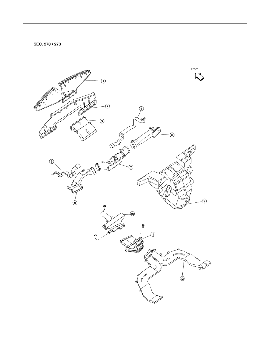
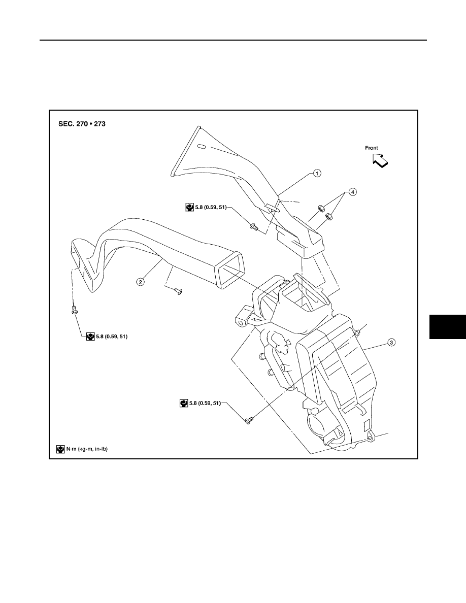
DUCTS AND GRILLES ........................................... 153
Components ......................................................... 153
Removal and Installation ...................................... 156
DEFROSTER NOZZLE ..................................... 156
FRESH AIR DUCT ............................................ 156
DEFROSTER DUCT ......................................... 156
RH AND LH SIDE DEMISTER DUCT ............... 156
RH, LH, AND CENTER VENTILATOR DUCT ... 156
FLOOR CONNECTOR DUCT ........................... 156
FLOOR DISTRIBUTION DUCT ......................... 156
FLOOR DUCT ................................................... 156
REAR OVERHEAD DUCT ................................ 156
REAR FLOOR DUCT ........................................ 157
GRILLES ........................................................... 157
REFRIGERANT LINES ........................................... 158
HFC-134a (R-134a) Service Procedure ............... 158
Components ......................................................... 160
Removal and Installation for Compressor ............ 162
Removal and Installation for Compressor Clutch . 163
REMOVAL ......................................................... 163
INSPECTION .................................................... 164
INSTALLATION ................................................. 164
BREAK-IN OPERATION .................................... 166
Removal and Installation for High-pressure Pipe . 166
REMOVAL ......................................................... 167
INSTALLATION ................................................. 167

ATC-4
Revision: May 2004
2004 Quest
Removal and Installation for Condenser ............... 167
REMOVAL ......................................................... 167
INSTALLATION .................................................. 168
Removal and Installation for Front Evaporator ..... 168
Removal and Installation for Rear Evaporator ...... 170
REMOVAL ......................................................... 170
INSTALLATION .................................................. 171
Removal and Installation for Front Expansion Valve .171
Removal and Installation for Rear Expansion Valve .171
REMOVAL ......................................................... 171
INSTALLATION .................................................. 172
Checking for Refrigerant Leaks ............................172
Checking System for Leaks Using the Fluorescent
Dye Leak Detector ................................................172
Dye Injection .........................................................172
Electronic Refrigerant Leak Detector ....................173
PRECAUTIONS FOR HANDLING LEAK
DETECTOR .......................................................173
CHECKING PROCEDURE ................................174
SERVICE DATA AND SPECIFICATIONS (SDS) ....176

PRECAUTIONS
ATC-5
C
D
E
F
G
H
I
K
L
M
A
B
ATC
Revision: May 2004
2004 Quest
PRECAUTIONS
PFP:00001
Precautions for Supplemental Restraint System (SRS) “AIR BAG” and “SEAT
BELT PRE-TENSIONER”
EJS001MN
The Supplemental Restraint System such as “AIR BAG” and “SEAT BELT PRE-TENSIONER”, used along
with a front seat belt, helps to reduce the risk or severity of injury to the driver and front passenger for certain
types of collision. This system includes seat belt switch inputs and dual stage front air bag modules. The SRS
system uses the seat belt switches to determine the front air bag deployment, and may only deploy one front
air bag, depending on the severity of a collision and whether the front occupants are belted or unbelted.
Information necessary to service the system safely is included in the SRS and SB section of this Service Man-
ual.
WARNING:
●
To avoid rendering the SRS inoperative, which could increase the risk of personal injury or death
in the event of a collision which would result in air bag inflation, all maintenance must be per-
formed by an authorized NISSAN/INFINITI dealer.
●
Improper maintenance, including incorrect removal and installation of the SRS, can lead to per-
sonal injury caused by unintentional activation of the system. For removal of Spiral Cable and Air
Bag Module, see the SRS section.
●
Do not use electrical test equipment on any circuit related to the SRS unless instructed to in this
Service Manual. SRS wiring harnesses can be identified by yellow and/or orange harnesses or
harness connectors.
Precautions for Working with HFC-134a (R-134a)
EJS001MO
WARNING:
●
CFC-12 (R-12) refrigerant and HFC-134a (R-134a) refrigerant are not compatible. If the refrigerants
are mixed compressor failure is likely to occur. Refer
ATC-5, "Contaminated Refrigerant"
. To
determine the purity of HFC-134a (R-134a) in the vehicle and recovery tank, use Refrigerant
Recovery/Recycling Recharging equipment and Refrigerant Identifier.
●
Use only specified lubricant for the HFC-134a (R-134a) A/C system and HFC-134a (R-134a) compo-
nents. If lubricant other than that specified is used, compressor failure is likely to occur.
●
The specified HFC-134a (R-134a) lubricant rapidly absorbs moisture from the atmosphere. The fol-
lowing handling precautions must be observed:
–
When removing refrigerant components from a vehicle, immediately cap (seal) the component to
minimize the entry of moisture from the atmosphere.
–
When installing refrigerant components to a vehicle, do not remove the caps (unseal) until just
before connecting the components. Connect all refrigerant loop components as quickly as possi-
ble to minimize the entry of moisture into system.
–
Only use the specified lubricant from a sealed container. Immediately reseal containers of lubri-
cant. Without proper sealing, lubricant will become moisture saturated and should not be used.
–
Avoid breathing A/C refrigerant and lubricant vapor or mist. Exposure may irritate eyes, nose and
throat. Remove HFC-134a (R-134a) from the A/C system using certified service equipment meeting
requirements of SAE J2210 [HFC-134a (R-134a) recycling equipment], or J2209 [HFC-134a (R-134a)
recovery equipment]. If accidental system discharge occurs, ventilate work area before resuming
service. Additional health and safety information may be obtained from refrigerant and lubricant
manufacturers.
–
Do not allow refrigerant lubricant to come in contact with styrofoam parts. Damage may result.
Contaminated Refrigerant
EJS001MP
If a refrigerant other than pure HFC-134a (R-134a) is identified in a vehicle, your options are:
●
Explain to the customer that environmental regulations prohibit the release of contaminated refrigerant
into the atmosphere.
●
Explain that recovery of the contaminated refrigerant could damage your service equipment and refriger-
ant supply.
●
Suggest the customer return the vehicle to the location of previous service where the contamination may
have occurred.
●
If you choose to perform the repair, recover the refrigerant using only dedicated equipment and contain-
ers. Do not recover contaminated refrigerant into your existing service equipment. If your facility

ATC-6
PRECAUTIONS
Revision: May 2004
2004 Quest
does not have dedicated recovery equipment, you may contact a local refrigerant product retailer for avail-
able service. This refrigerant must be disposed of in accordance with all federal and local regulations. In
addition, replacement of all refrigerant system components on the vehicle is recommended.
●
If the vehicle is within the warranty period, the air conditioner warranty is void. Please contact Nissan Cus-
tomer Affairs for further assistance.
General Refrigerant Precautions
EJS001MQ
WARNING:
●
Do not release refrigerant into the air. Use approved recovery/recycling equipment to capture the
refrigerant every time an air conditioning system is discharged.
●
Always wear eye and hand protection (goggles and gloves) when working with any refrigerant or
air conditioning system.
●
Do not store or heat refrigerant containers above 52
°
C (125
°
F).
●
Do not heat a refrigerant container with an open flame; if container warming is required, place the
bottom of the container in a warm pail of water.
●
Do not intentionally drop, puncture, or incinerate refrigerant containers.
●
Keep refrigerant away from open flames: poisonous gas will be produced if refrigerant burns.
●
Refrigerant will displace oxygen, therefore be certain to work in well ventilated areas to prevent
suffocation.
●
Do not pressure test or leak test HFC-134a (R-134a) service equipment and/or vehicle air condi-
tioning systems with compressed air during repair. Some mixtures of air and HFC-134a (R-134a)
have been shown to be combustible at elevated pressures. These mixtures, if ignited, may cause
injury or property damage. Additional health and safety information may be obtained from refriger-
ant manufacturers.
Precautions for Leak Detection Dye
EJS001MR
●
The A/C system contains a fluorescent leak detection dye used for locating refrigerant leaks. An ultraviolet
(UV) lamp is required to illuminate the dye when inspecting for leaks.
●
Always wear fluorescence enhancing UV safety glasses to protect your eyes and enhance the visibility of
the fluorescent dye.
●
The fluorescent dye leak detector is not a replacement for an electronic refrigerant leak detector. The fluo-
rescent dye leak detector should be used in conjunction with an electronic refrigerant leak detector (J-
41995).
●
For your safety and the customer's satisfaction, read and follow all manufacturer's operating instructions
and precautions prior to performing work.
●
A compressor shaft seal should not be repaired because of dye seepage. The compressor shaft seal
should only be repaired after confirming the leak with an electronic refrigerant leak detector (J-41995).
●
Always remove any dye from the leak area after repairs are complete to avoid a misdiagnosis during a
future service.
●
Do not allow dye to come into contact with painted body panels or interior components. If dye is spilled,
clean immediately with the approved dye cleaner. Fluorescent dye left on a surface for an extended period
of time cannot be removed .
●
Do not spray the fluorescent dye cleaning agent on hot surfaces (engine exhaust manifold, etc.).
●
Do not use more than one refrigerant dye bottle (1/4 ounce / 7.4 cc) per A/C system.
●
Leak detection dyes for HFC-134a (R-134a) and CFC-12 (R-12) A/C systems are different. Do not use
HFC-134a (R-134a) leak detection dye in CFC-12 (R-12) A/C systems or CFC-12 (R-12) leak detection
dye in HFC-134A (R-134a) A/C systems or A/C system damage may result.
●
The fluorescent properties of the dye will remain for over three (3) years unless a compressor failure
occurs.
PRECAUTIONS
ATC-7
C
D
E
F
G
H
I
K
L
M
A
B
ATC
Revision: May 2004
2004 Quest
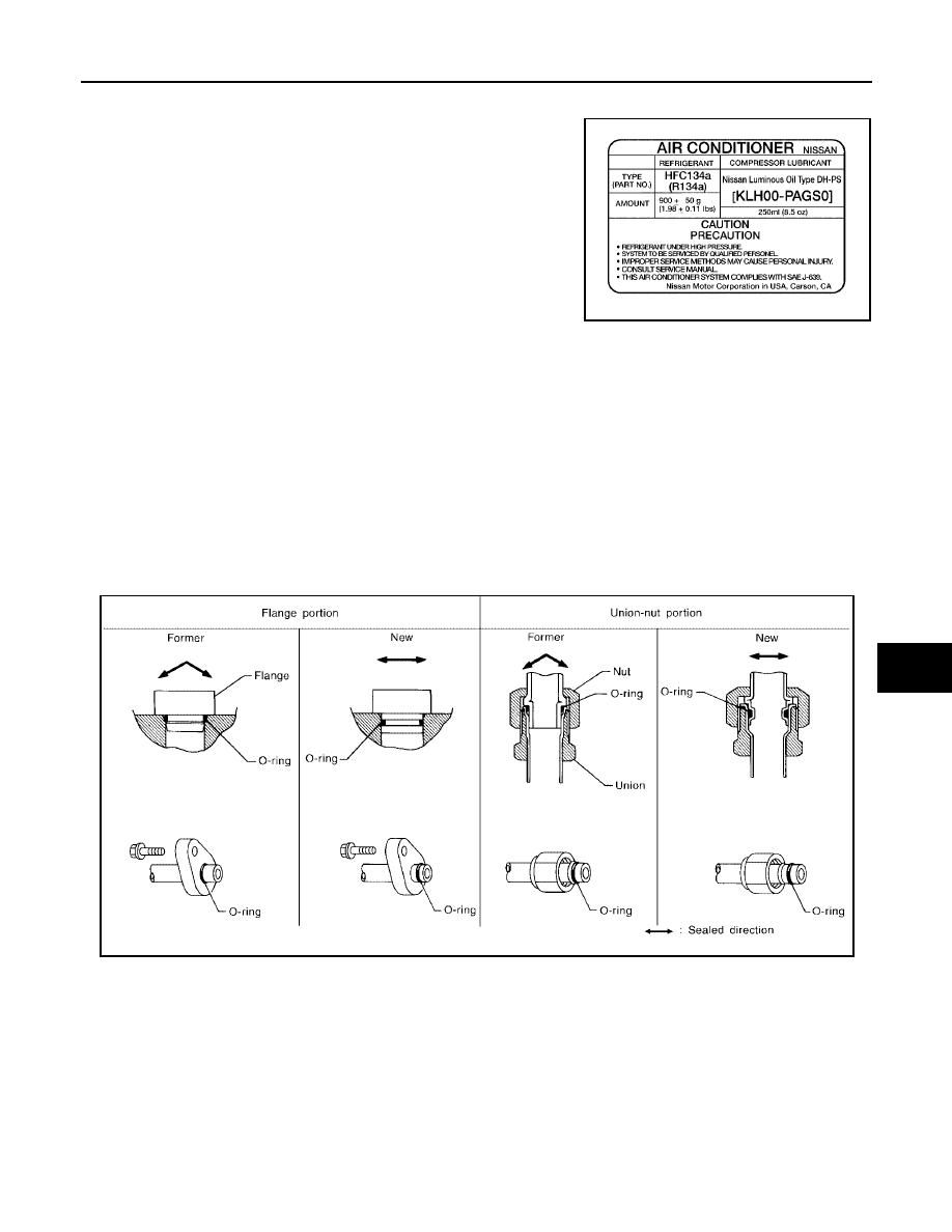
A/C Identification Label
EJS001MS
Vehicles with factory installed fluorescent dye have this identification
label on the underside of hood.
Precautions for Refrigerant Connection
EJS001MT
A new type refrigerant connection has been introduced to all refrigerant lines except the following locations.
●
Expansion valve to cooling unit
●
Evaporator pipes to evaporator (inside cooling unit)
●
Refrigerant pressure sensor
FEATURES OF NEW TYPE REFRIGERANT CONNECTION
●
The O-ring has been relocated. It has also been provided with a groove for proper installation. This
reduces the possibility of the O-ring being caught in, or damaged by, the mating part. The sealing direction
of the O-ring is now set vertically in relation to the contacting surface of the mating part to improve sealing
characteristics.
●
The reaction force of the O-ring will not occur in the direction that causes the joint to pull out, thereby facil-
itating piping connections.
WJIA0383E
SHA815E
ATC-8
PRECAUTIONS
Revision: May 2004
2004 Quest
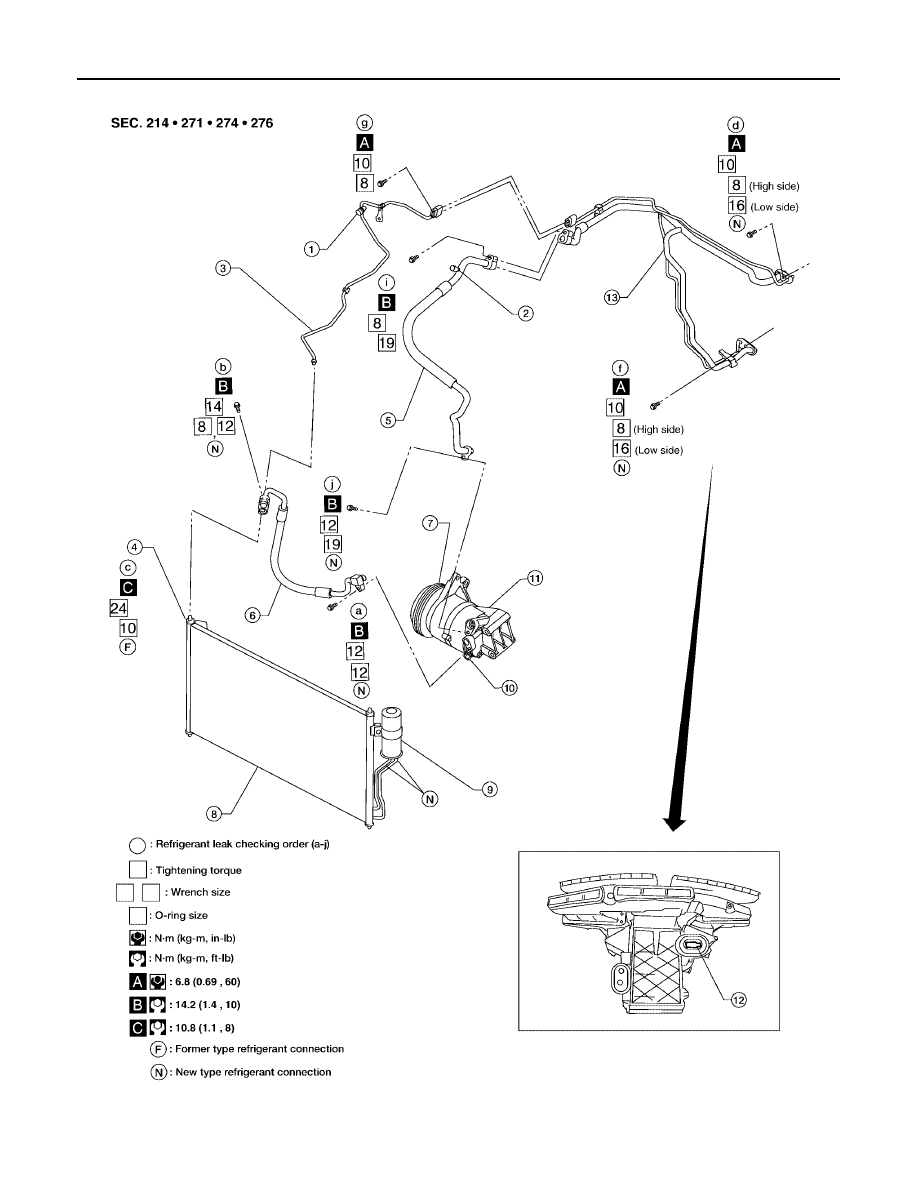
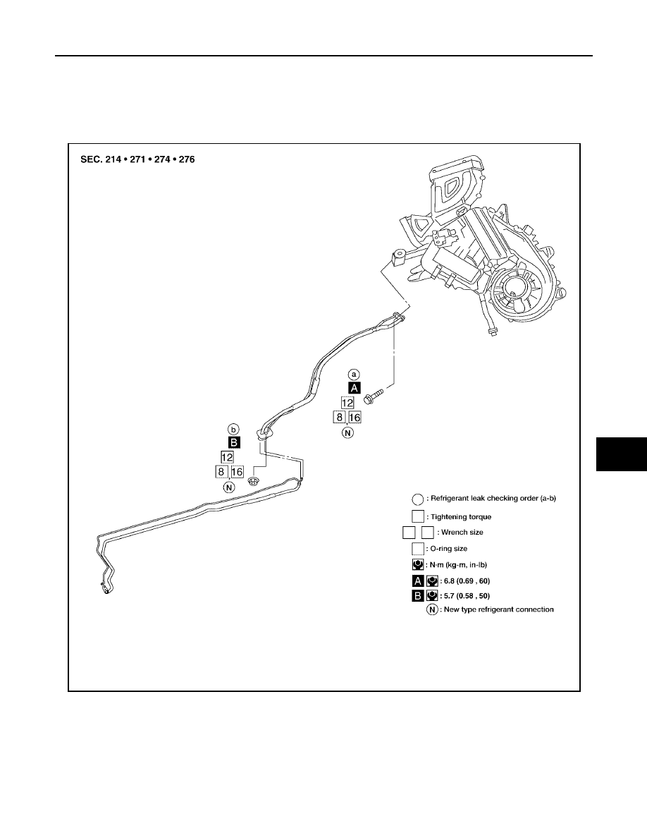
O-RING AND REFRIGERANT CONNECTION
WJIA0370E
PRECAUTIONS
ATC-9
C
D
E
F
G
H
I
K
L
M
A
B
ATC
Revision: May 2004
2004 Quest
CAUTION:
The new and former refrigerant connections use different O-ring configurations. Do not confuse O-
rings since they are not interchangeable. If a wrong O-ring is installed, refrigerant will leak at or
around the connection.
1.
High-pressure service valve
2.
Low-pressure service valve
3.
High-pressure pipe
4.
Refrigerant pressure sensor
5.
Low-pressure flexible hose
6.
High-pressure flexible hose
7.
Shaft seal
8.
Condenser
9.
Liquid tank
10. Pressure relief valve
11.
Compressor
12. Evaporator
13. High/low pressure pipe
LJIA0016E
ATC-10
PRECAUTIONS
Revision: May 2004
2004 Quest
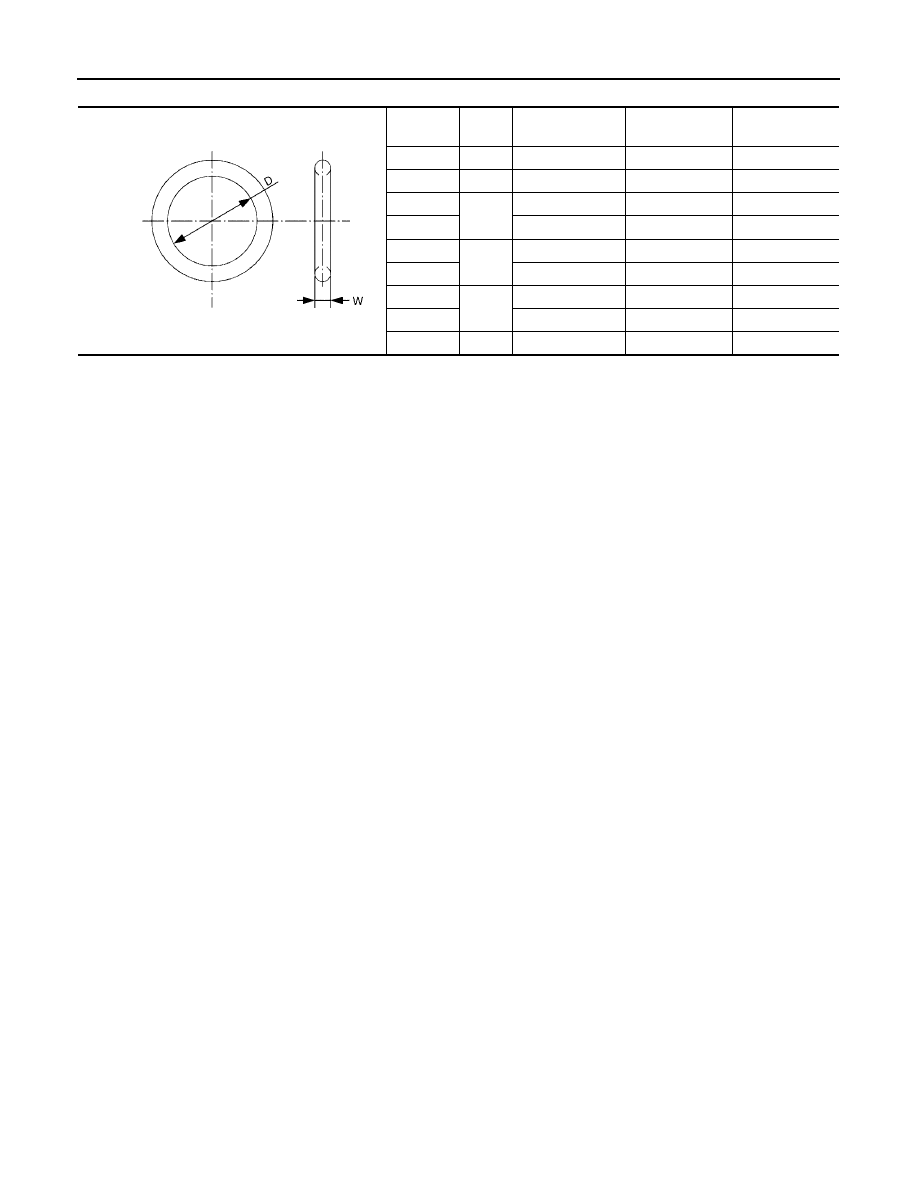
O-Ring Part Numbers and Specifications
*: Always check with the Parts Department for the latest parts information.
WARNING:
Make sure all refrigerant is discharged into the recycling equipment and the pressure in the system is
less than atmospheric pressure. Then gradually loosen the discharge side hose fitting and remove it.
CAUTION:
When replacing or cleaning refrigerant cycle components, observe the following.
●
When the compressor is removed, store it in the same position as it is when mounted on the car.
Failure to do so will cause lubricant to enter the low pressure chamber.
●
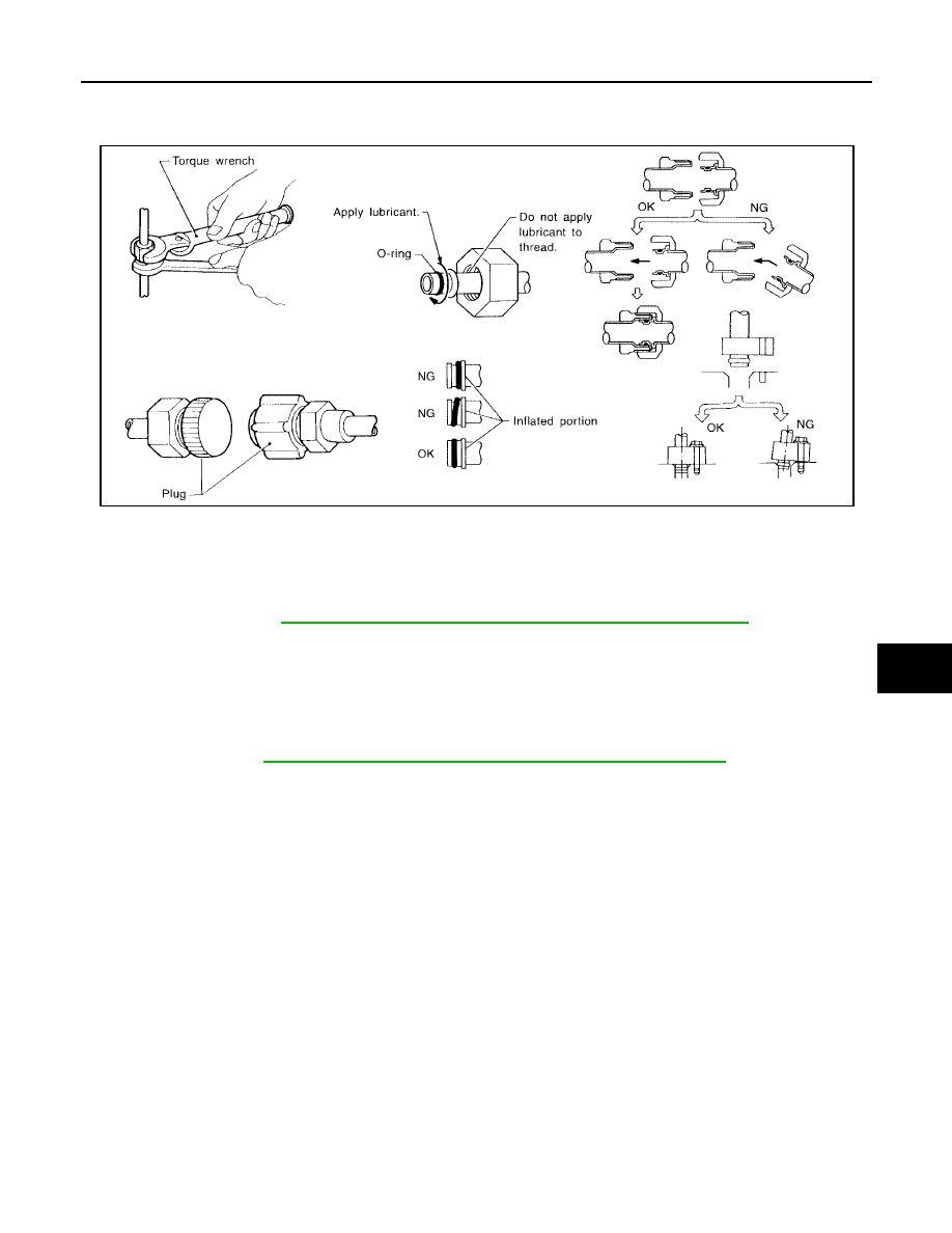
When connecting tubes, always use a torque wrench and a back-up wrench.
●
After disconnecting tubes, immediately plug all openings to prevent entry of dirt and moisture.
●
When installing an air conditioner in the vehicle, connect the pipes as the final stage of the opera-
tion. Do not remove the seal caps of pipes and other components until just before required for
connection.
●
Allow components stored in cool areas to warm to working area temperature before removing seal
caps. This prevents condensation from forming inside A/C components.
●
Thoroughly remove moisture from the refrigeration system before charging the refrigerant.
●
Always replace used O-rings.
●
When connecting tube, apply lubricant to circle of the O-rings shown in illustration. Be careful not
to apply lubricant to threaded portion.
●
O-ring must be closely attached to dented portion of tube.
●
When replacing the O-ring, be careful not to damage O-ring and tube.
●
Connect tube until you hear it click, then tighten the nut or bolt by hand until snug. Make sure that
the O-ring is installed to tube correctly.
Connec-
tion type
O-ring
size
Part number*
D
mm (in)
W
mm (in)
New
8
92471 N8210
6.8 (0.268)
1.85 (0.0728)
Former
10
J2476 89956
9.25 (0.3642)
1.78 (0.0701)
New
12
92472 N8210
10.9 (0.429)
2.43 (0.0957)
Former
92475 71L00
11.0 (0.433)
2.4 (0.094)
New
16
92473 N8210
13.6 (0.535)
2.43 (0.0957)
Former
92475 72L00
14.3 (0.563)
2.3 (0.091)
New
19
92474 N8210
16.5 (0.650)
2.43 (0.0957)
Former
92477 N8200
17.12 (0.6740)
1.78 (0.0701)
New
24
92195 AH300
21.8 (0.858)
2.4 (0.094)
SHA814E
PRECAUTIONS
ATC-11
C
D
E
F
G
H
I
K
L
M
A
B
ATC
Revision: May 2004
2004 Quest
●
After connecting line, conduct leak test and make sure that there is no leakage from connections.
When the gas leaking point is found, disconnect that line and replace the O-ring. Then tighten con-
nections of seal seat to the specified torque.
Precautions for Servicing Compressor
EJS001MU
●
Plug all openings to prevent moisture and foreign matter from entering.
●
When the compressor is removed, store it in the same position as it is when mounted on the car.
●
When replacing or repairing compressor, follow “Maintenance of Lubricant Quantity in Compres-
sor” exactly. Refer to
ATC-22, "Maintenance of Lubricant Quantity in Compressor"
●
Keep friction surfaces between clutch and pulley clean. If the surface is contaminated with lubri-
cant, wipe it off by using a clean waste cloth moistened with thinner.
●
After compressor service operation, turn the compressor shaft by hand more than 5 turns in both
directions. This will equally distribute lubricant inside the compressor. After the compressor is
installed, let the engine idle and operate the compressor for 1 hour.
●
After replacing the compressor magnet clutch, apply voltage to the new one and check for normal
operation. Refer to
ATC-163, "Removal and Installation for Compressor Clutch"
Precautions for Service Equipment
EJS001MV
RECOVERY/RECYCLING EQUIPMENT
Follow the manufacturer's instructions for machine operation and machine maintenance. Never introduce any
refrigerant other than that specified into the machine.
ELECTRONIC LEAK DETECTOR
Follow the manufacturer's instructions for tester operation and tester maintenance.
RHA861F
ATC-12
PRECAUTIONS
Revision: May 2004
2004 Quest
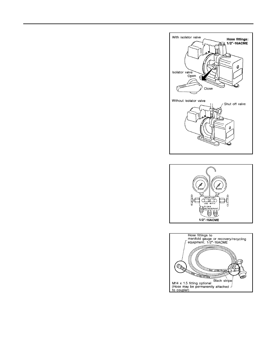
VACUUM PUMP
The lubricant contained inside the vacuum pump is not compatible
with the specified lubricant for HFC-134a (R-134a) A/C systems.
The vent side of the vacuum pump is exposed to atmospheric pres-
sure so the vacuum pump lubricant may migrate out of the pump into
the service hose. This is possible when the pump is switched off
after evacuation (vacuuming) and hose is connected to it.
To prevent this migration, use a manual valve situated near the
hose-to-pump connection, as follows.
●
Usually vacuum pumps have a manual isolator valve as part of
the pump. Close this valve to isolate the service hose from the
pump.
●
For pumps without an isolator, use a hose equipped with a man-
ual shut-off valve near the pump end. Close the valve to isolate
the hose from the pump.
●
If the hose has an automatic shut off valve, disconnect the hose
from the pump: as long as the hose is connected, the valve is
open and lubricating oil may migrate.
Some one-way valves open when vacuum is applied and close
under a no vacuum condition. Such valves may restrict the pump's
ability to pull a deep vacuum and are not recommended.
MANIFOLD GAUGE SET
Be certain that the gauge face indicates HFC-134a (R-134a or
134a). Make sure the gauge set has 1/2
″
-16 ACME threaded con-
nections for service hoses. Confirm the set has been used only with
refrigerant HFC-134a (R-134a) along with specified lubricant.
SERVICE HOSES
Be certain that the service hoses display the markings described
(colored hose with black stripe). All hoses must include positive shut-
off devices (either manual or automatic) near the end of the hoses
opposite the manifold gauge.
RHA270D
SHA533D
RHA272D
PRECAUTIONS
ATC-13
C
D
E
F
G
H
I
K
L
M
A
B
ATC
Revision: May 2004
2004 Quest
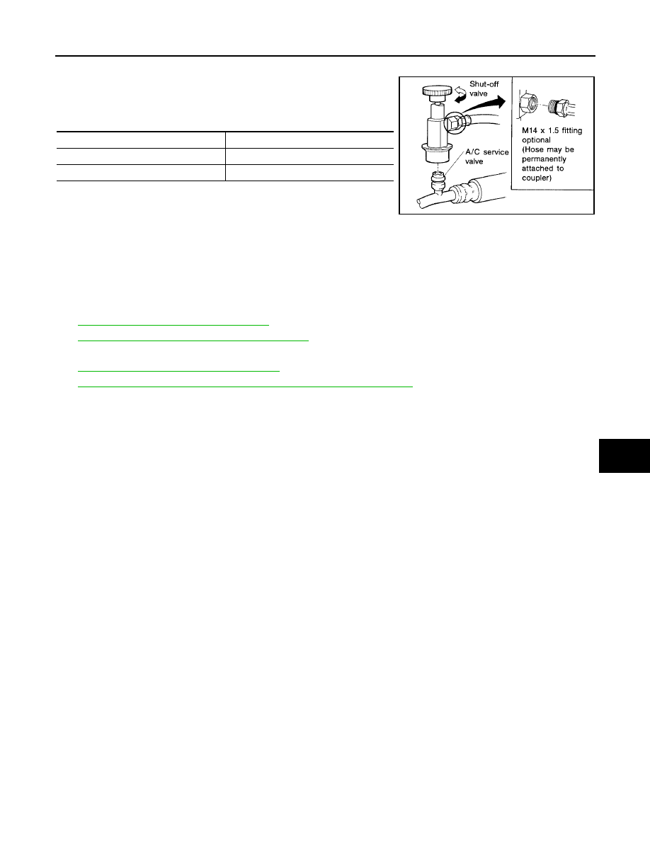
SERVICE COUPLERS
Never attempt to connect HFC-134a (R-134a) service couplers to a
CFC-12 (R-12) A/C system. The HFC-134a (R-134a) couplers will
not properly connect to the CFC-12 (R-12) system. If an improper
connection is attempted, discharging and contamination may occur.
CHARGING CYLINDER
Using a charging cylinder is not recommended. Refrigerant may be vented into air from cylinder's top valve
when filling the cylinder with refrigerant. Also, the accuracy of the cylinder is generally less than that of an
electronic scale or of quality recycle/recharge equipment.
Wiring Diagrams and Trouble Diagnosis
EJS001MW
When you read wiring diagrams, refer to the following:
●
GI-12, "How to Read Wiring Diagrams"
●
PG-4, "POWER SUPPLY ROUTING CIRCUIT"
When you perform trouble diagnosis, refer to the following:
●
GI-9, "How to Follow Trouble Diagnoses"
●
GI-25, "How to Perform Efficient Diagnosis for an Electrical Incident"
Shut-off valve rotation
A/C service valve
Clockwise
Open
Counterclockwise
Close
RHA273D
ATC-14
PREPARATION
Revision: May 2004
2004 Quest
PREPARATION
PFP:00002
Special Service Tools
EJS001MX
The actual shapes of Kent-Moore tools may differ from those of special service tools illustrated here.
HFC-134a (R-134a) Service Tools and Equipment
EJS001MY
Never mix HFC-134a refrigerant and/or its specified lubricant with CFC-12 (R-12) refrigerant and/or its lubri-
cant.
Separate and non-interchangeable service equipment must be used for handling each type of refrigerant/lubri-
cant.
Refrigerant container fittings, service hose fittings and service equipment fittings (equipment which handles
refrigerant and/or lubricant) are different between CFC-12 (R-12) and HFC-134a (R-134a). This is to avoid
mixed use of the refrigerants/lubricant.
Adapters that convert one size fitting to another must never be used refrigerant/lubricant contamination will
occur and compressor failure will result.
Tool number
(Kent-Moore No.)
Tool name
Description
KV99234330
(J-38873A)
Pulley installer
Installing pulley
KV99233130
(J-29884)
Pulley puller
Removing pulley
LHA171
LHA172
Tool number
(Kent-Moore No.)
Tool name
Description
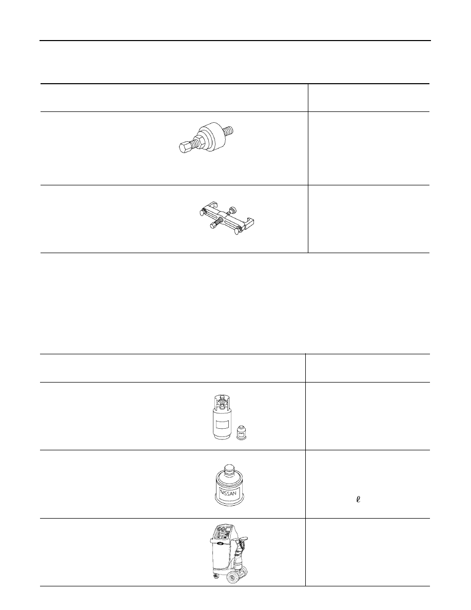
HFC-134a (R-134a) refrigerant
Container color: Light blue
Container marking: HFC-134a (R-
134a)
Fitting size: Thread size
●
large container 1/2"-16 ACME
KLH00-PAGS0
( - )
Nissan A/C System Lubricant Type
S (DH-PS)
Type: Poly alkylene glycol oil (PAG),
type DH-PS
Application: HFC-134a (R-134a)
swash plate compressors (Nissan
only)
Lubricity: 40 m
(1.4 US fl oz, 1.4 Imp
fl oz)
(J-43600)
Recovery/Recycling
Recharging equipment (ACR2000)
Function: Refrigerant Recovery and
Recycling and Recharging
S-NT196
S-NT197
WJIA0293E
PREPARATION
ATC-15
C
D
E
F
G
H
I
K
L
M
A
B
ATC
Revision: May 2004
2004 Quest
(J-41995)
Electronic refrigerant leak detector
Power supply:
●
DC 12V (Cigarette lighter)
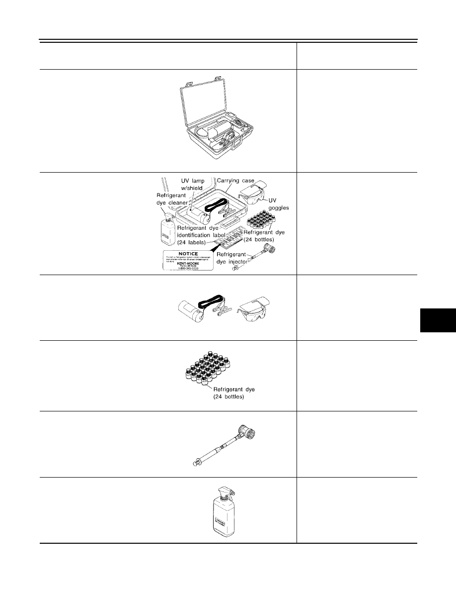
(J-43926)
Refrigerant dye leak detection kit
Kit includes:
(J-42220) UV lamp and UV safety
goggles
(J-41459) Refrigerant dye injector
(J-41447) qty. 24
HFC-134a (R-134a) refrigerant
dye
(J-43872) Refrigerant dye cleaner
Power supply:
●
DC 12V (Battery terminal)
(J-42220)
Fluorescent dye leak detector
Power supply:
●
DC 12V (Battery terminal)
For checking refrigerant leak when flu-
orescent dye is installed in A/C system.
Includes: UV lamp and UV safety gog-
gles
(J-41447)
HFC-134a (R-134a) Fluorescent
leak detection dye
(Box of 24, 1/4 ounce bottles)
Application: For HFC-134a (R-134a)
PAG oil
Container: 1/4 ounce (7.4cc) bottle
(Includes self-adhesive dye identifica-
tion labels for affixing to vehicle after
charging system with dye.)
(J-41459)
HFC-134a (R-134a) Dye injector
Use with J-41447, 1/4 ounce bottle
For injecting 1/4 ounce of fluorescent
leak detection dye into A/C system.
(J-43872)
Dye cleaner
For cleaning dye spills.
Tool number
(Kent-Moore No.)
Tool name
Description
AHA281A
ZHA200H
SHA438F
SHA439F
SHA440F
SHA441F
ATC-16
PREPARATION
Revision: May 2004
2004 Quest
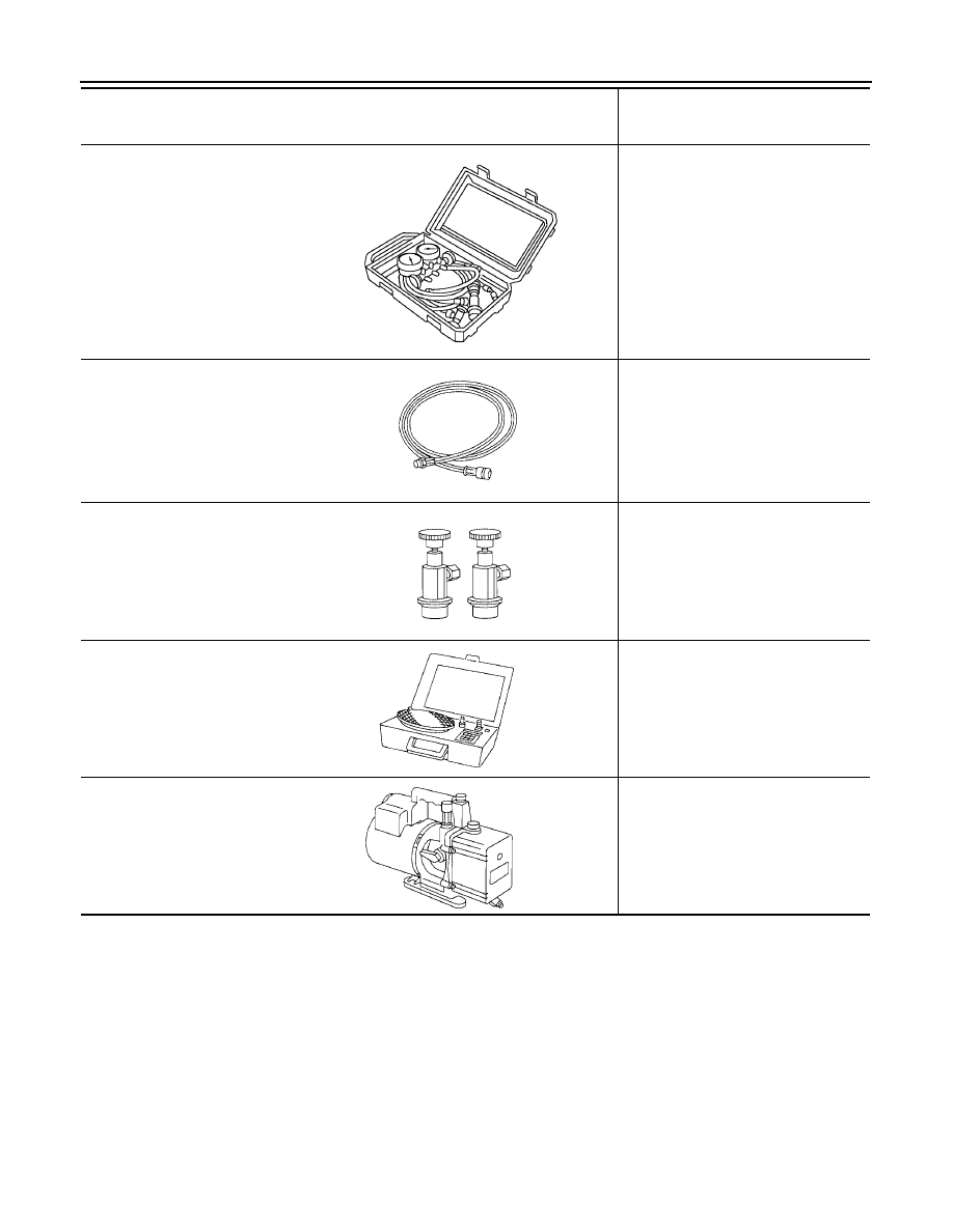
(J-39183-C)
Manifold gauge set (with hoses
and couplers)
Identification:
●
The gauge face indicates R-134a.
Fitting size-Thread size
●
1/2"-16 ACME
Service hoses
●
High side hose
(J-39500-72B)
●
Low side hose
(J-39500-72R)
●
Utility hose
(J-39500-72Y)
Hose color:
●
Low side hose: Blue with black stripe
●
High side hose: Red with black stripe
●
Utility hose: Yellow with black stripe
or green with black stripe
Hose fitting to gauge:
●
1/2"-16 ACME
Service couplers
●
High side coupler
(J-39500-20A)
●
Low side coupler
(J-39500-24A)
Hose fitting to service hose:
●
M14 x 1.5 fitting is optional or perma-
nently attached.
(J-39699)
Refrigerant weight scale
For measuring of refrigerant
Fitting size-Thread size
●
1/2"-16 ACME
(J-39649)
Vacuum pump
(Including the isolator valve)
Capacity:
●
Air displacement: 4 CFM
●
Micron rating: 20 microns
●
Oil capacity: 482 g (17 oz)
Fitting size-Thread size
●
1/2"-16 ACME
Tool number
(Kent-Moore No.)
Tool name
Description
RJIA0196E
S-NT201
S-NT202
S-NT200
S-NT203
PREPARATION
ATC-17
C
D
E
F
G
H
I
K
L
M
A
B
ATC
Revision: May 2004
2004 Quest
Commercial Service Tools
EJS001MZ
Tool name
Description
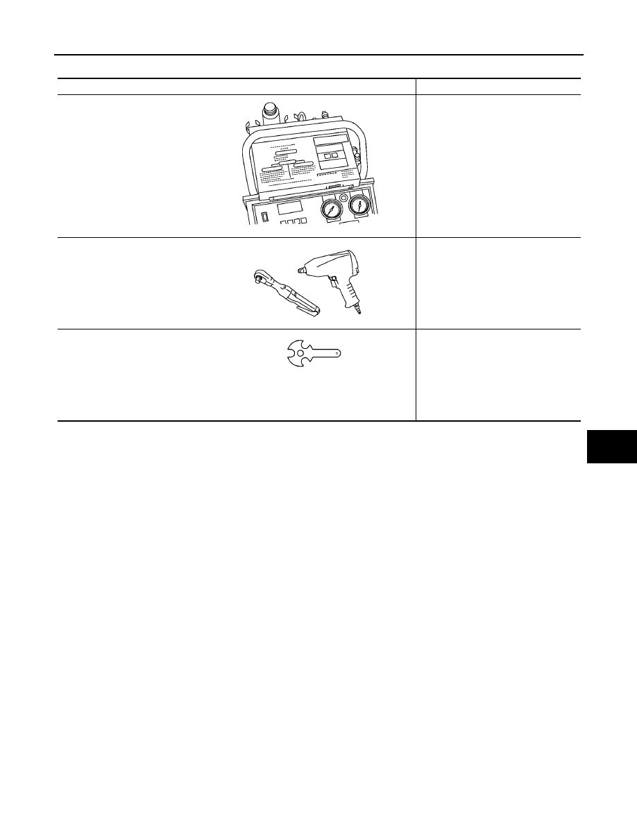
(J-41810-NI)
Refrigerant identifier equipment-
(R-134a)
For checking refrigerant purity and
system contamination
Power tool
Loosening bolts and nuts
(J-44614)
Clutch disc holding tool
Clutch disc holding tool
RJIA0197E
PBIC0190E
WHA230

ATC-18
REFRIGERATION SYSTEM
Revision: May 2004
2004 Quest
REFRIGERATION SYSTEM
PFP:KA990
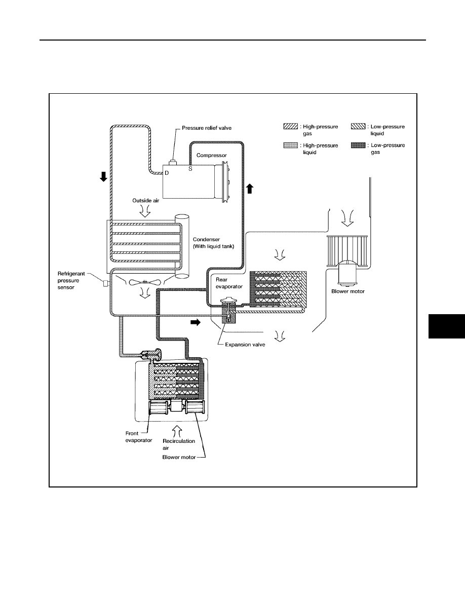
Refrigerant Cycle
EJS001N0
REFRIGERANT FLOW
The refrigerant flows in the standard pattern, that is, through the compressor, the condenser with liquid tank,
through the front and rear evaporators, and back to the compressor. The refrigerant evaporation through the
evaporator coils are controlled by a front and rear externally equalized expansion valves, located inside the
front and rear evaporator cases.
Refrigerant System Protection
EJS001N1
REFRIGERANT PRESSURE SENSOR
The refrigerant system is protected against excessively high or low pressures by the refrigerant pressure sen-
sor, located on the condenser. If the system pressure rises above or falls below the specifications, the refriger-
ant pressure sensor detects the pressure inside the refrigerant line and sends a voltage signal to the ECM.
The ECM deenergizes the A/C relay to disengage the magnetic compressor clutch when pressure on the high
pressure side detected by refrigerant pressure sensor is over about 2,746 kPa (28 kg/cm
2
, 398 psi), or below
about 120 kPa (1.22 kg/cm
2
, 17.4 psi).
REFRIGERATION SYSTEM
ATC-19
C
D
E
F
G
H
I
K
L
M
A
B
ATC
Revision: May 2004
2004 Quest
PRESSURE RELIEF VALVE
The refrigerant system is also protected by a pressure relief valve, located in the rear head of the compressor.
When the pressure of refrigerant in the system increases to an abnormal level [more than 2,990 kPa (30.5 kg/
cm
2
, 433.6 psi)], the release port on the pressure relief valve automatically opens and releases refrigerant
into the atmosphere.
WJIA0384E
ATC-20
REFRIGERATION SYSTEM
Revision: May 2004
2004 Quest
Component Layout
EJS001N2
FRONT REFRIGERATION SYSTEM
LJIA0085E
REFRIGERATION SYSTEM
ATC-21
C
D
E
F
G
H
I
K
L
M
A
B
ATC
Revision: May 2004
2004 Quest
REAR REFRIGERATION SYSTEM
1.
Defroster nozzle
2.
Fresh air duct
3.
Defroster duct
4.
Demister duct (right side)
5.
Demister duct (left side)
6.
Ventilator duct (RH mid-level duct)
7.
Ventilator duct (center mid-level
duct)
8.
Ventilator duct (LH mid-level duct) 9.
Front heater and cooling unit assembly
10. Floor duct
11. Floor (distribution) duct
12. Floor duct
1
Rear overhead duct
2
Rear heat duct
3
Rear heater and cooling unit assembly
LJIA0086E
ATC-22
LUBRICANT
Revision: May 2004
2004 Quest
LUBRICANT
PFP:KLG00
Maintenance of Lubricant Quantity in Compressor
EJS001N3
The lubricant in the compressor circulates through the system with the refrigerant. Add lubricant to compres-
sor when replacing any component or after a large refrigerant leakage has occurred. It is important to maintain
the specified amount.
If lubricant quantity is not maintained properly, the following malfunctions may result:
●
Lack of lubricant: May lead to a seized compressor
●
Excessive lubricant: Inadequate cooling (thermal exchange interference)
LUBRICANT
Name: Nissan A/C System Lubricant Type (DH-PS)
Part number: KLH00-PAGS0
CHECKING AND ADJUSTING
CAUTION:
If excessive lubricant leakage is noted, do not perform the lubricant return operation.
Start the engine and set the following conditions:
test condition
●
Engine speed: Idling to 1,200 rpm
●
A/C switch: On
●
Blower speed: Max. position
●
Temp. control: Optional [Set so that intake air temperature is 25 to 30
°
C (77 to 86
°
F).]
●
Intake position: Recirculation (
)
●
Perform lubricant return operation for about ten minutes
Adjust the lubricant quantity according to the following table.
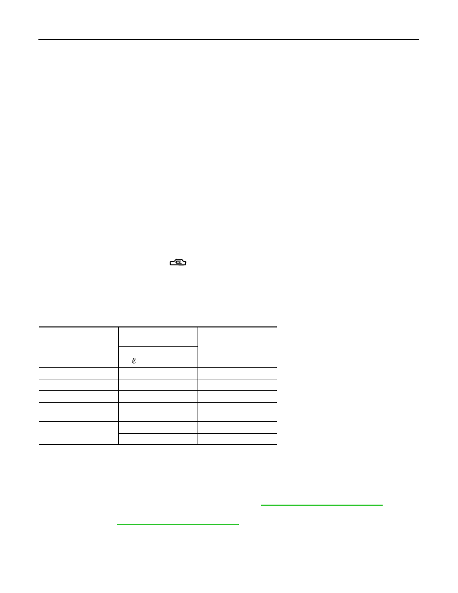
Lubricant Adjusting Procedure for Components Replacement Except Compressor
After replacing any of the following major components, add the correct amount of lubricant to the system.
Amount of lubricant to be added
●
*1:
If refrigerant leak is small, no addition of lubricant is needed.
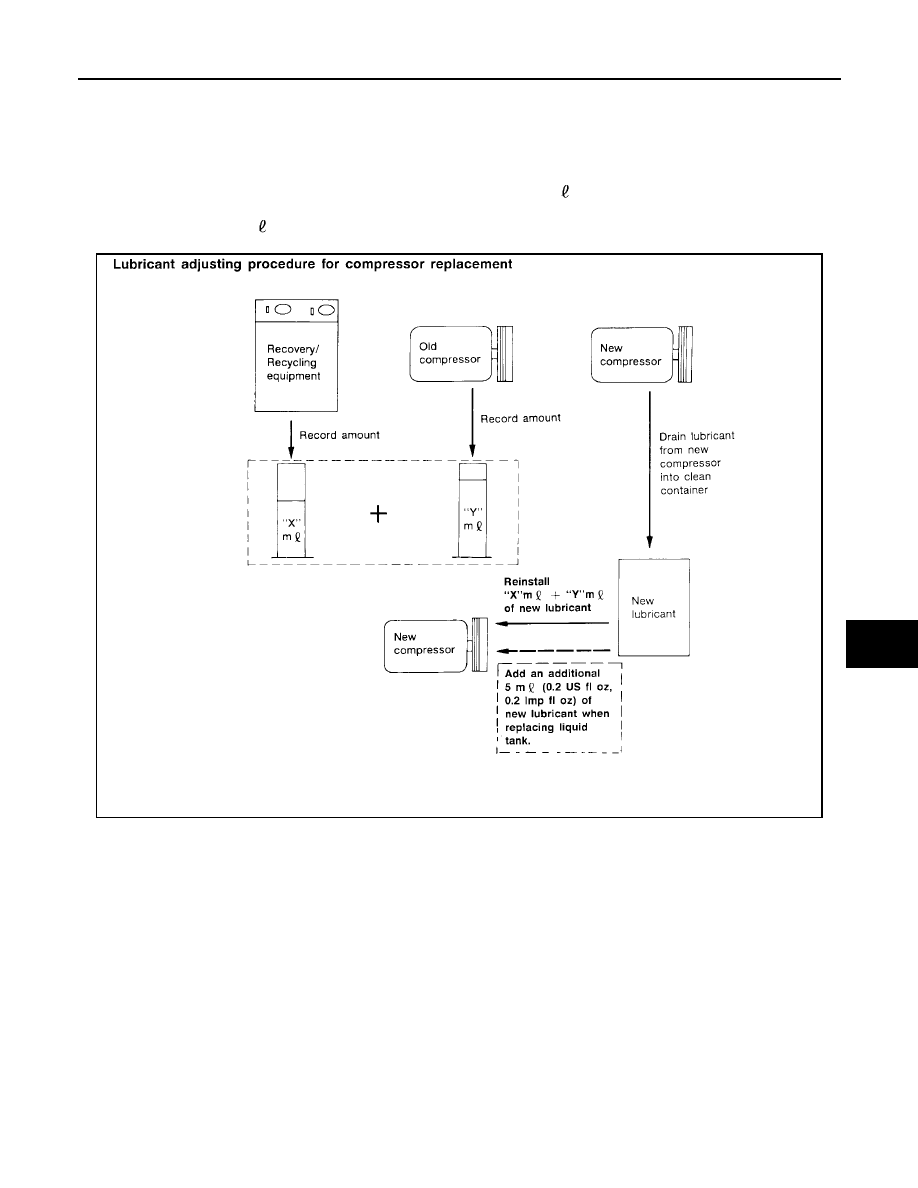
Lubricant Adjustment Procedure for Compressor Replacement
1.
Before connecting recovery/recycling equipment to vehicle, check recovery/recycling equipment gauges.
No refrigerant pressure should be displayed. If NG, recover refrigerant from equipment lines.
2.
Connect recovery/recycling equipment to vehicle. Confirm refrigerant purity in supply tank using recovery/
recycling equipment and refrigerant identifier. If NG, refer to
ATC-5, "Contaminated Refrigerant"
3.
Confirm refrigerant purity in vehicle A/C system using recovery/recycling equipment and refrigerant identi-
fier. If NG, refer to
ATC-5, "Contaminated Refrigerant"
4.
Discharge refrigerant into the refrigerant recovery/recycling equipment. Measure lubricant discharged into
the recovery/recycling equipment.
5.
Drain the lubricant from the “old” (removed) compressor into a graduated container and recover the
amount of lubricant drained.
Part replaced
Lubricant to be added to
system
Remarks
Amount of lubricant
m
(US fl oz, Imp fl oz)
Front evaporator
75 (2.5, 2.6)
—
Rear evaporator
75 (2.5, 2.6)
—
Condenser
75 (2.5, 2.6)
—
Liquid tank
5 (0.2, 0.2)
Add if compressor is not
replaced.
In case of refrigerant leak
30 (1.0, 1.1)
Large leak
—
Small leak *1
LUBRICANT
ATC-23
C
D
E
F
G
H
I
K
L
M
A
B
ATC
Revision: May 2004
2004 Quest
6.
Drain the lubricant from the “new” compressor into a separate, clean container.
7.
Measure an amount of new lubricant installed equal to amount drained from “old” compressor. Add this
lubricant to “new” compressor through the suction port opening.
8.
Measure an amount of new lubricant equal to the amount recovered during discharging. Add this lubricant
to “new” compressor through the suction port opening.
9.
If the liquid tank also needs to be replaced, add an additional 5 m (0.2 US fl oz, 0.2 Imp fl oz) of lubricant
at this time.
Do not add this 5 m (0.2 US fl oz, 0.2 Imp fl oz) of lubricant if only replacing the compressor.
RHA065DD

ATC-24
AIR CONDITIONER CONTROL
Revision: May 2004
2004 Quest
AIR CONDITIONER CONTROL
PFP:27500
Description
EJS001QW
The front air control provides automatic regulation of the vehicle's interior temperature. The system is based
on the driver's and passenger's selected "set temperature", regardless of the outside temperature changes.
This is done by utilizing a microcomputer, also referred to as the front air control, which receives input signals
from the following five sensors:
●
Ambient sensor
●
In-vehicle sensor
●
Intake sensor
●
Optical sensor (one sensor for driver and passenger side)
●
PBR (Position Balanced Resistor).
The front air control uses these signals (including the set temperature) to automatically control:
●
Outlet air volume
●
Air temperature
●
Air distribution
The front air control also provides separate regulation of the vehicle's interior temperature for the rear passen-
ger area. The system is based on the temperature and rear blower settings selected from rear control
switches located on the front air control, or from the temperature and rear blower settings selected from rear
control switches on the rear air control, when the front air control switches are set to the rear position.
The front air control is used to select:
●
Outlet air volume
●
Air temperature/distribution
Operation
EJS001N5
AIR MIX DOORS CONTROL (AUTOMATIC TEMPERATURE CONTROL)
The air mix doors are automatically controlled so that in-vehicle temperature is maintained at a predetermined
value by: The temperature setting, ambient temperature, in-vehicle temperature and amount of sunload.
FAN SPEED CONTROL
Blower speed is automatically controlled based on temperature setting, ambient temperature, in-vehicle tem-
perature, intake temperature, amount of sunload and air mix door position.
When AUTO switch is pressed, the blower motor starts to gradually increase air flow volume (if required).
When engine coolant temperature is low, the blower motor operation is delayed to prevent cool air from flow-
ing.
INTAKE DOORS CONTROL
The intake doors are automatically controlled by: The temperature setting, ambient temperature, in-vehicle
temperature, intake temperature, amount of sunload and ON-OFF operation of the compressor.
MODE DOOR CONTROL
The mode door is automatically controlled by: The temperature setting, ambient temperature, in-vehicle tem-
perature, intake temperature and amount of sunload.
DEFROSTER DOOR CONTROL
The defroster door is controlled by: Turning the defroster dial to front defroster.
AIR CONDITIONER CONTROL
ATC-25
C
D
E
F
G
H
I
K
L
M
A
B
ATC
Revision: May 2004
2004 Quest
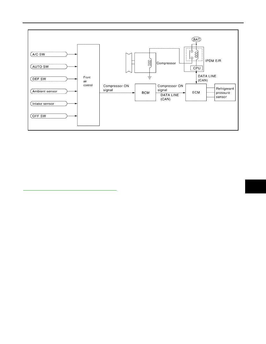
MAGNET CLUTCH CONTROL
When A/C switch or DEF switch is pressed, front air control inputs compressor ON signal to BCM.
BCM sends compressor ON signal to ECM, via CAN communication line.
ECM judges whether compressor can be turned ON, based on each sensor status (refrigerant pressure sen-
sor signal, throttle angle sensor, etc.). If it judges compressor can be turned ON, it sends compressor ON sig-
nal to IPDM E/R, via CAN communication line.
Upon receipt of compressor ON signal from ECM, IPDM E/R turns air conditioner relay ON to operate com-
pressor.
SELF-DIAGNOSTIC SYSTEM
The self-diagnostic system is built into the front air control to quickly locate the cause of symptoms. Refer to
ATC-50, "A/C System Self-diagnosis Function"
LJIA0023E
ATC-26
AIR CONDITIONER CONTROL
Revision: May 2004
2004 Quest
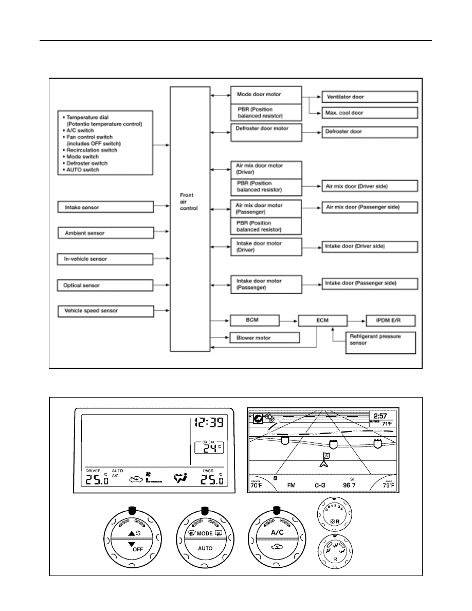
Description of Control System
EJS001N6
The control system consists of input sensors, switches, the front air control (microcomputer) and outputs.
The relationship of these components is shown in the figure below:
Control Operation
EJS001N7
Front air control
WJIA0385E
WJIA0386E
AIR CONDITIONER CONTROL
ATC-27
C
D
E
F
G
H
I
K
L
M
A
B
ATC
Revision: May 2004
2004 Quest
Rear air control
DISPLAY SCREEN
Displays the operational status of the system.
AUTO SWITCH
●
The compressor, intake doors, air mix doors, outlet doors and blower speed are automatically controlled
so that the in-vehicle temperature will reach, and be maintained at the set temperature selected by the
operator.
●
When pressing AUTO switch, air inlet, air outlet, fan speed, and discharge air temperature are automati-
cally controlled.
TEMPERATURE SWITCH (TEMPERATURE CONTROL) (DRIVER SIDE)
Increases or decreases the set temperature.
TEMPERATURE SWITCH (TEMPERATURE CONTROL) (PASSENGER SIDE)
Increases or decreases the set temperature.
TEMPERATURE SWITCH (TEMPERATURE CONTROL) (REAR)
Increases or decreases the set temperature.
RECIRCULATION () SWITCH
●
When REC switch is ON, REC switch indicator turns ON, and air inlet is set to REC.
●
When REC switch is turned OFF, or when compressor is turned from ON to OFF, REC switch is automati-
cally turned OFF. REC mode can be re-entered by pressing REC switch again.
●
REC switch is not operated when DEF switch is turned ON, or at the D/F position.
DEFROSTER (DEF) SWITCH
Positions the air outlet doors to the defrost position. Also positions the intake doors to the outside air position.
REAR WINDOW DEFOGGER SWITCH
When switch is ON, rear window is defogged.
OFF SWITCH
The compressor and blower are OFF, the intake doors are set to the outside air position, and the air outlet
doors are set to the foot (75% foot and 25% defrost) position.
A/C SWITCH
The compressor is ON or OFF.
(Pressing the A/C switch when the AUTO switch is ON will turn off the A/C switch and compressor.)
MODE SWITCH
Controls the air discharge outlets.
LJIA0024E
ATC-28
AIR CONDITIONER CONTROL
Revision: May 2004
2004 Quest
FRONT FAN CONTROL SWITCH
Manually control the blower speed. Seven speeds are available for manual control (as shown on the display
screen).
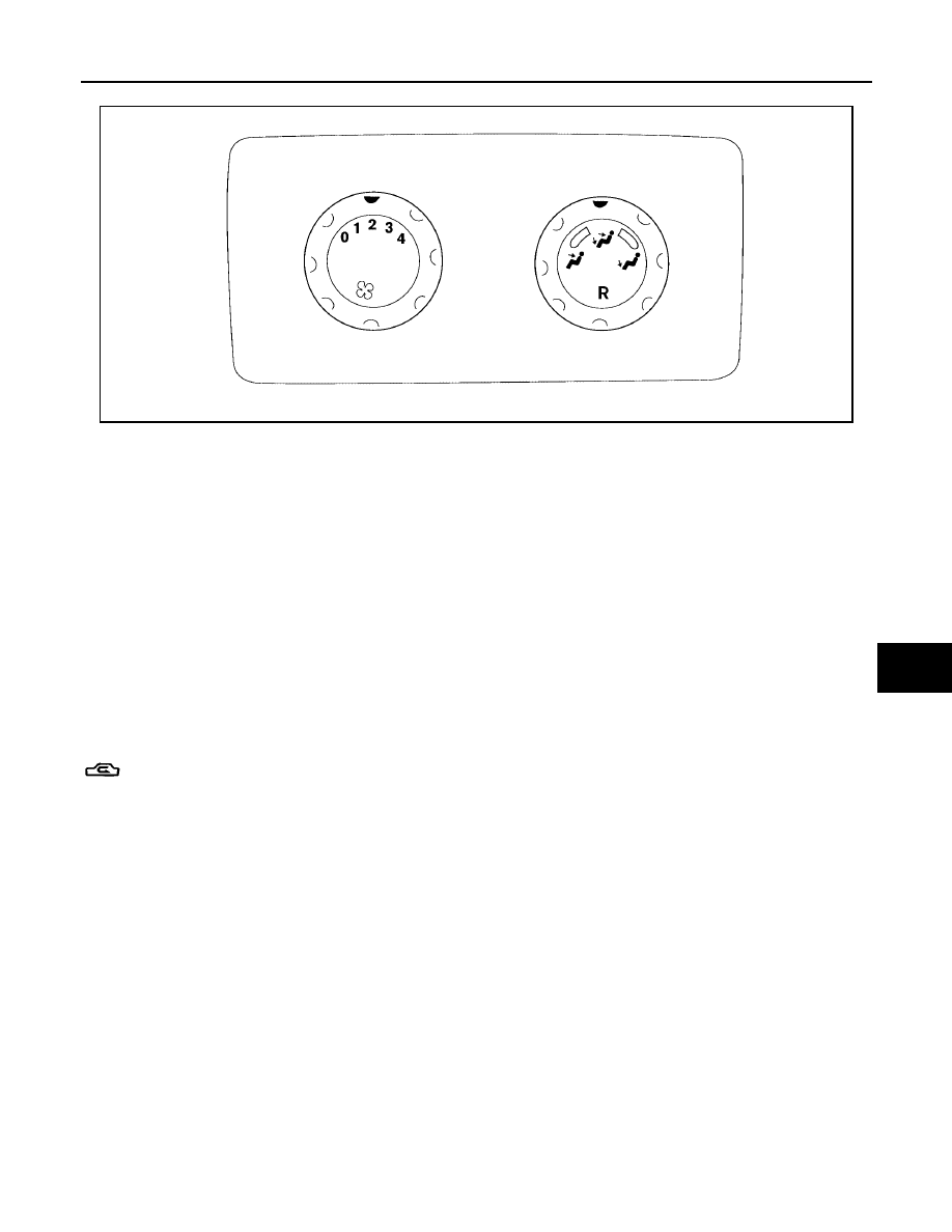
REAR FAN CONTROL SWITCH
When the rear fan switch (front) is in the OFF position, the rear blower motor cannot operate.
When the rear fan switch (front) is in the REAR position, it allows the rear fan switch (rear) to control the rear
blower motor speed. In any other position (1-4), the rear fan switch (front) controls the rear blower motor
speed regardless of the rear fan switch (rear) position.
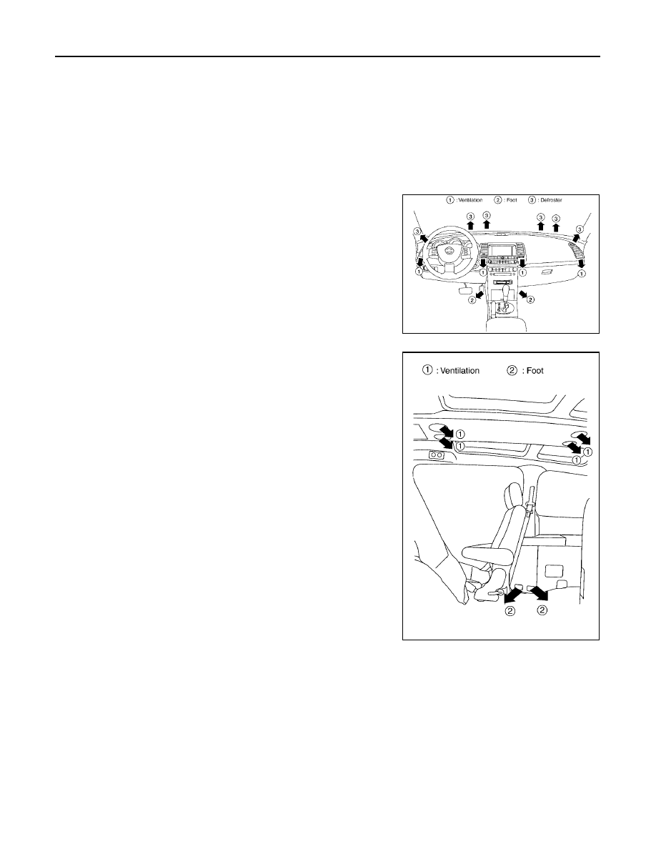
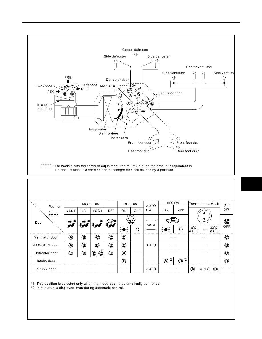
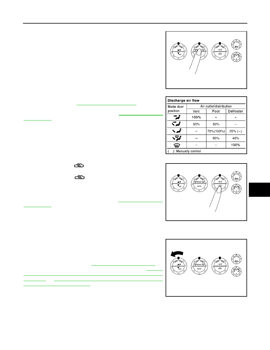
Discharge Air Flow
EJS001N9
FRONT
REAR
LJIA0025E
LJIA0127E
AIR CONDITIONER CONTROL
ATC-29
C
D
E
F
G
H
I
K
L
M
A
B
ATC
Revision: May 2004
2004 Quest
System Description
EJS001NA
SWITCHES AND THEIR CONTROL FUNCTION
WJIA0387E
WJIA0388E

ATC-30
AIR CONDITIONER CONTROL
Revision: May 2004
2004 Quest
CAN Communication System Description
EJS001NB
.
TROUBLE DIAGNOSIS
ATC-31
C
D
E
F
G
H
I
K
L
M
A
B
ATC
Revision: May 2004
2004 Quest
TROUBLE DIAGNOSIS
PFP:00004
CONSULT-II
EJS001NC
CONSULT-II executes the following functions by combining data reception and command transmission via the
communication line from BCM data monitor display.
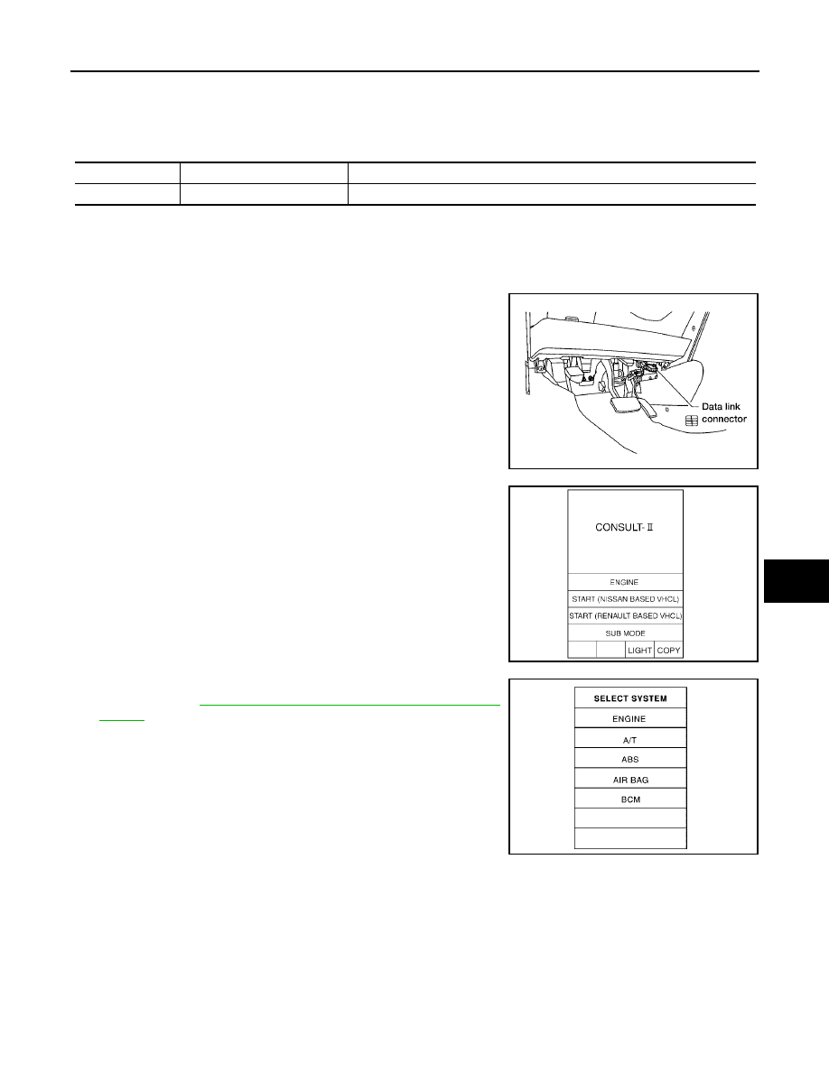
CONSULT-II BASIC OPERATION
CAUTION:
If CONSULT-II is used with no connection of CONSULT-II CONVERTER, malfunctions might be
detected in self-diagnosis depending on control unit which carry out CAN communication.
1.
With the ignition switch OFF, connect CONSULT-II and CON-
SULT-II converter to the data link connector, and turn the ignition
switch ON.
2.
Touch “START (NISSAN BASED VHCL)”.
3.
Touch “BCM” on “SELECT SYSTEM” screen. If “BCM” is not
indicated, go to
GI-36, "CONSULT-II Data Link Connector (DLC)
System part
Check item, diagnosis mode
Description
BCM
Data monitor
Displays BCM input data in real time.
BBIA0336E
SKIA3098E
WJIA0389E
ATC-32
TROUBLE DIAGNOSIS
Revision: May 2004
2004 Quest
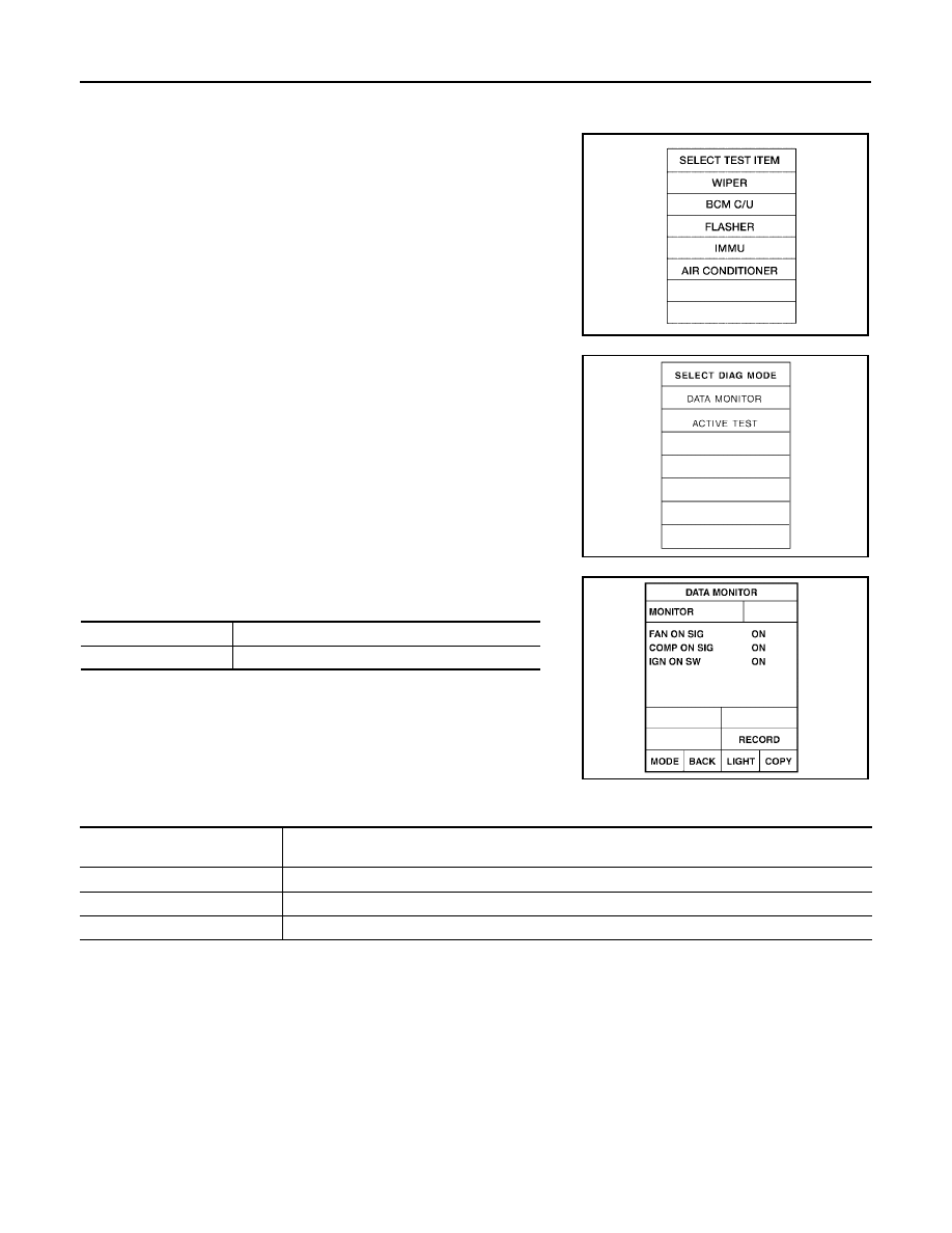
DATA MONITOR
Operation Procedure
1.
Touch “AIR CONDITIONER” on “SELECT TEST ITEM” screen.
2.
Touch “DATA MONITOR” on “SELECT DIAG MODE” screen.
3.
Touch either “ALL SIGNALS” or “SELECTION FROM MENU” on
“DATA MONITOR” screen.
4.
Touch “START”.
5.
When “SELECTION FROM MENU” is selected, touch items to
be monitored. When “ALL SIGNALS” is selected, all the items
will be monitored.
6.
Touch “RECORD” while monitoring, then the status of the moni-
tored item can be recorded. To stop recording, touch “STOP”.
Display Item List
WJIA0468E
SJIA0269E
All signals
Monitors all the items.
Selection from menu
Selects and monitors the individual item selected.
WJIA0469E
Monitor item name “operation or
unit”
Contents
IGN ON SW
“ON/OFF”
Displays “IGN Position (ON)/OFF, ACC Position (OFF)” status as judged from ignition switch signal.
COMP ON SIG
“ON/OFF”
Displays “COMP (ON)/COMP (OFF)” status as judged from air conditioner switch signal.
FAN ON SIG
“ON/OFF”
Displays “FAN (ON)/FAN (OFF)” status as judged from blower fan motor switch signal.
TROUBLE DIAGNOSIS
ATC-33
C
D
E
F
G
H
I
K
L
M
A
B
ATC
Revision: May 2004
2004 Quest
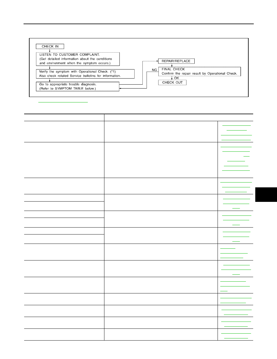
How to Perform Trouble Diagnosis for Quick and Accurate Repair
EJS001ND
WORK FLOW
SYMPTOM TABLE
*1
SHA900E
Symptom
Reference Page
A/C system does not come on.
Go to Trouble Diagnosis Procedure for A/C System.
A/C system display is malfunctioning.
Go to "Navigation System", or "Integrated Display System".
(With Navi.)
(Without Navi.)
A/C system cannot be controlled.
Go to Self-diagnosis Function.
Air outlet does not change.
Go to Trouble Diagnosis Procedure for Mode Door Motor.
Mode door motor is malfunctioning.
Discharge air temperature does not change.
Go to Trouble Diagnosis Procedure for Air Mix Door Motor.
Air mix door motor is malfunctioning.
Intake door does not change.
Go to Trouble Diagnosis Procedure for Intake Door Motor.
Intake door motor is malfunctioning.
Defroster door motor is malfunctioning.
Go to Trouble Diagnosis Procedure for Defroster Door Motor.
ATC-75,
"Defroster Door
Motor Circuit"
Front blower motor operation is malfunction-
ing.
Go to Trouble Diagnosis Procedure for Front Blower Motor.
Rear blower motor operation is malfunction-
ing.
Go to Trouble Diagnosis Procedure for Rear Blower Motor.
ATC-85, "Rear
Blower Motor Cir-
cuit"
Rear discharge air temperature and/or air
outlet does not change.
Go to Trouble Diagnosis Procedure for Rear Air Control circuit.
ATC-96, "Rear Air
Control Circuit"
Magnet clutch does not engage.
Go to Trouble Diagnosis Procedure for Magnet Clutch.
Insufficient cooling
Go to Trouble Diagnosis Procedure for Insufficient Cooling.
Insufficient heating
Go to Trouble Diagnosis Procedure for Insufficient Heating.

ATC-34
TROUBLE DIAGNOSIS
Revision: May 2004
2004 Quest
Noise
Go to Trouble Diagnosis Procedure for Noise.
Self-diagnosis cannot be performed.
Go to Trouble Diagnosis Procedure for Self-diagnosis.
Memory function does not operate.
Go to Trouble Diagnosis Procedure for Memory Function.
Symptom
Reference Page
TROUBLE DIAGNOSIS
ATC-35
C
D
E
F
G
H
I
K
L
M
A
B
ATC
Revision: May 2004
2004 Quest
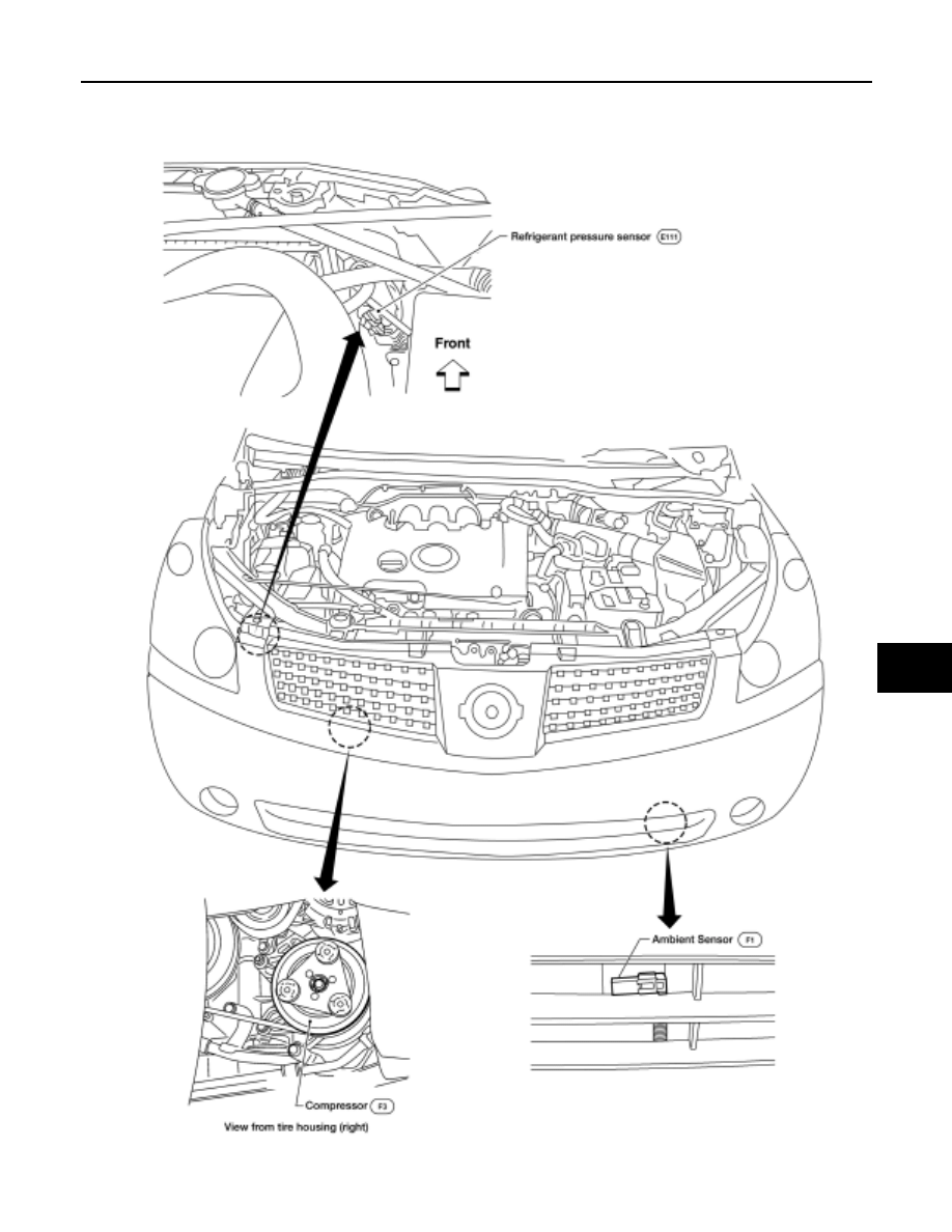
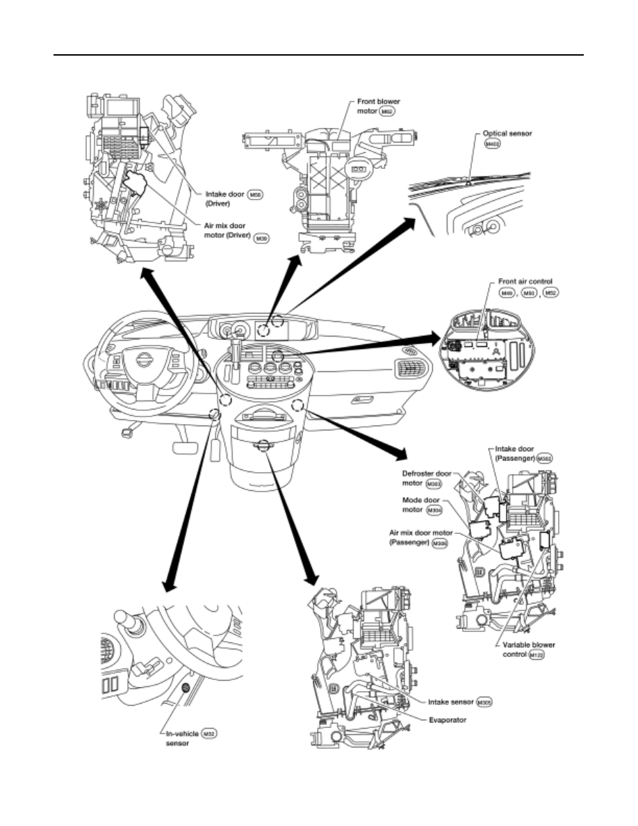
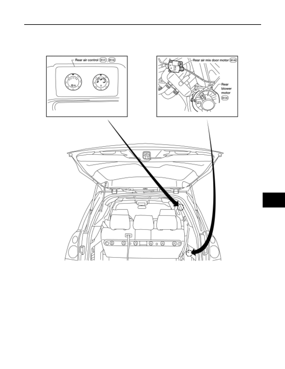
Component Parts and Harness Connector Location
EJS001NE
ENGINE COMPARTMENT
WJIA0390E
ATC-36
TROUBLE DIAGNOSIS
Revision: May 2004
2004 Quest
FRONT PASSENGER COMPARTMENT
WJIA0391E
TROUBLE DIAGNOSIS
ATC-37
C
D
E
F
G
H
I
K
L
M
A
B
ATC
Revision: May 2004
2004 Quest
REAR PASSENGER COMPARTMENT
LJIA0123E
ATC-38
TROUBLE DIAGNOSIS
Revision: May 2004
2004 Quest
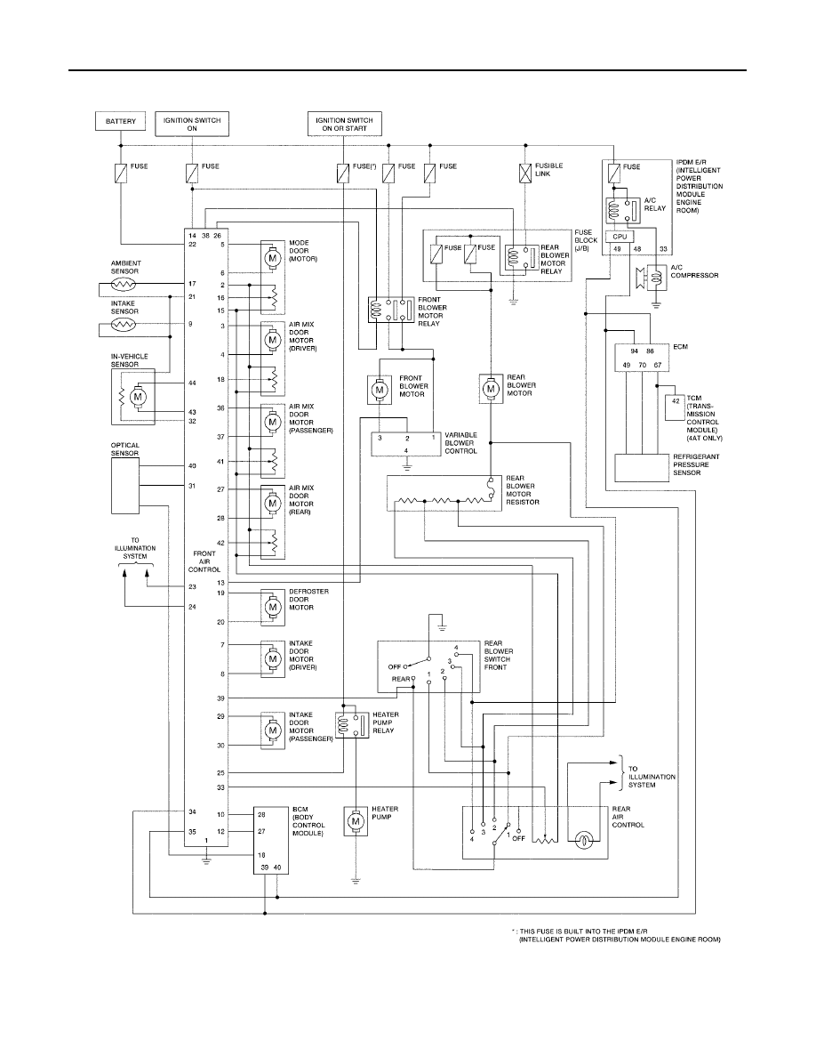
Schematic
EJS001NF
LJWA0001E
TROUBLE DIAGNOSIS
ATC-39
C
D
E
F
G
H
I
K
L
M
A
B
ATC
Revision: May 2004
2004 Quest
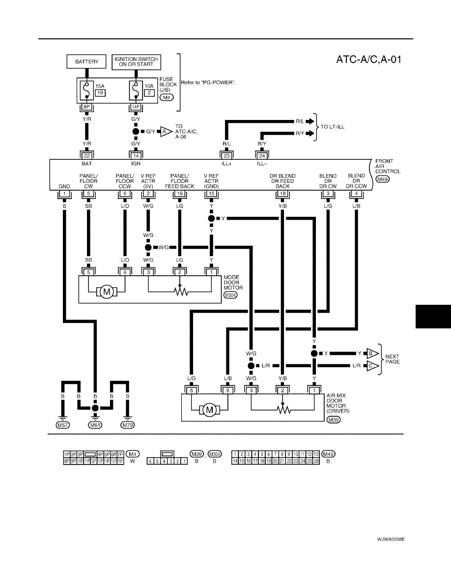
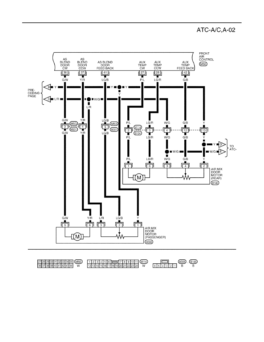
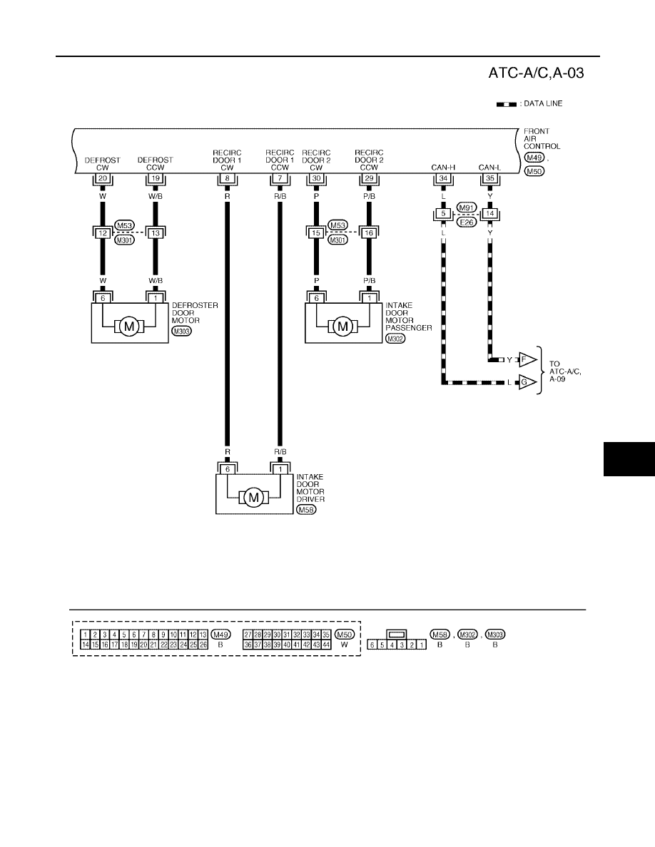
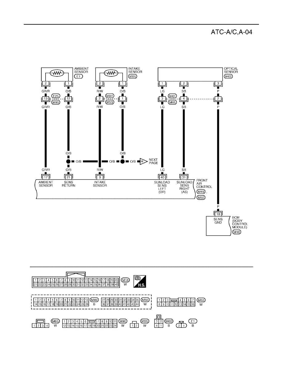
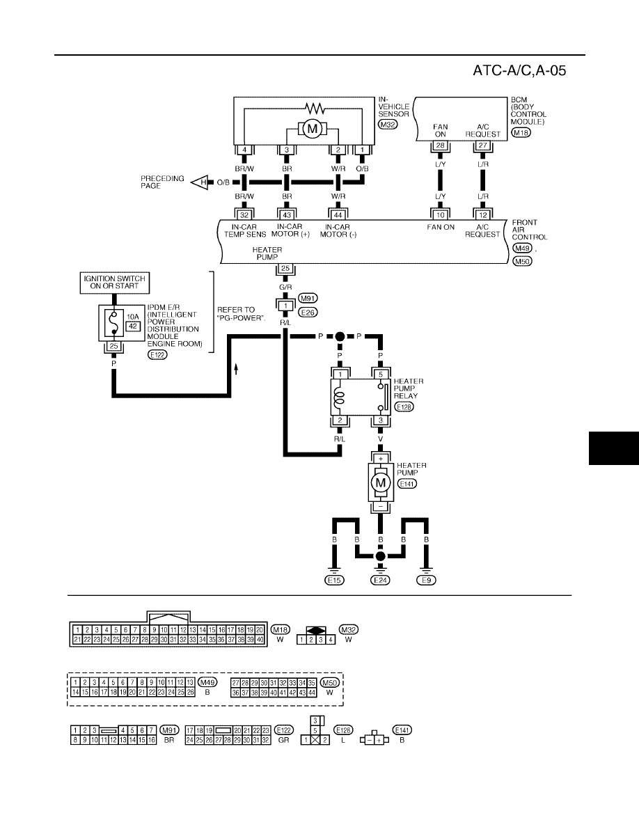
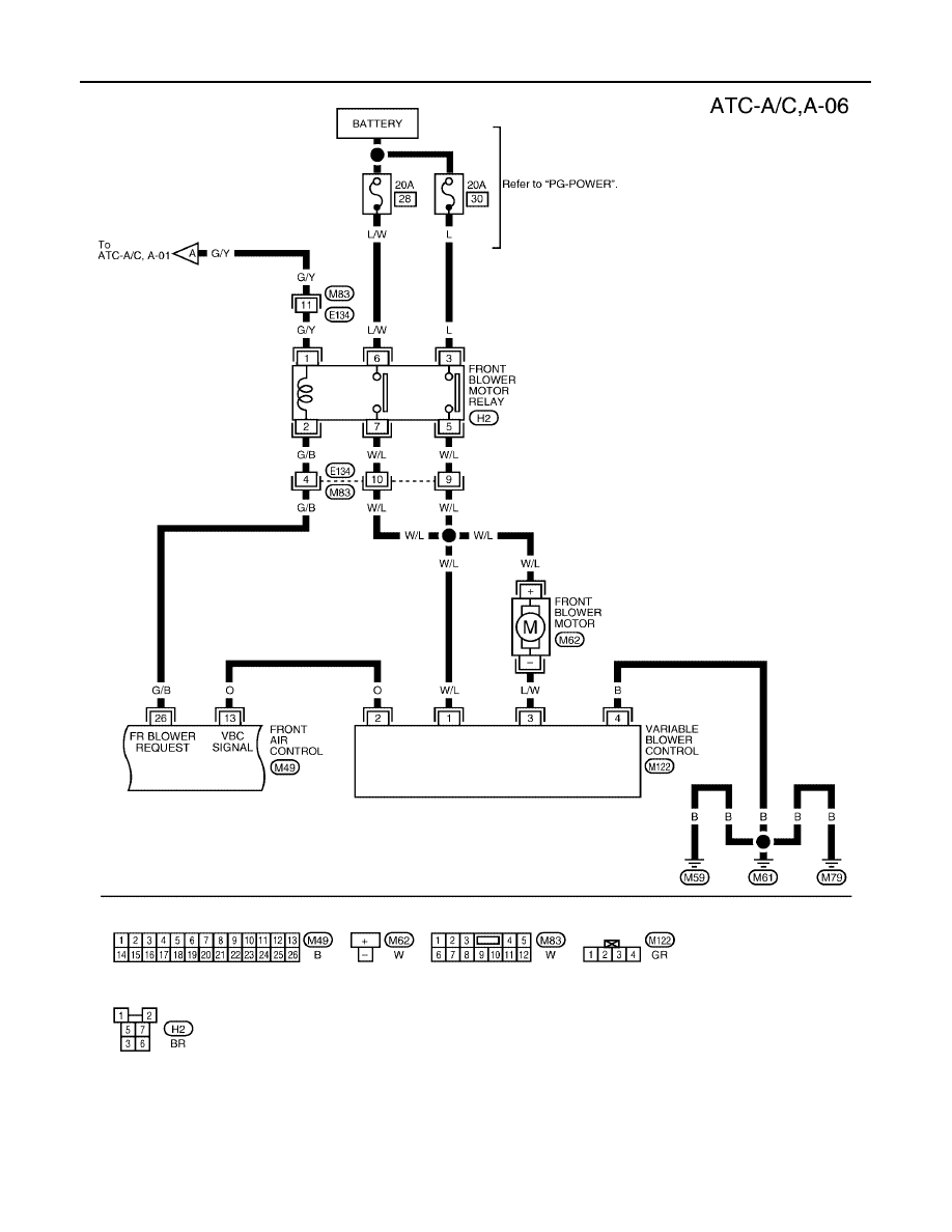
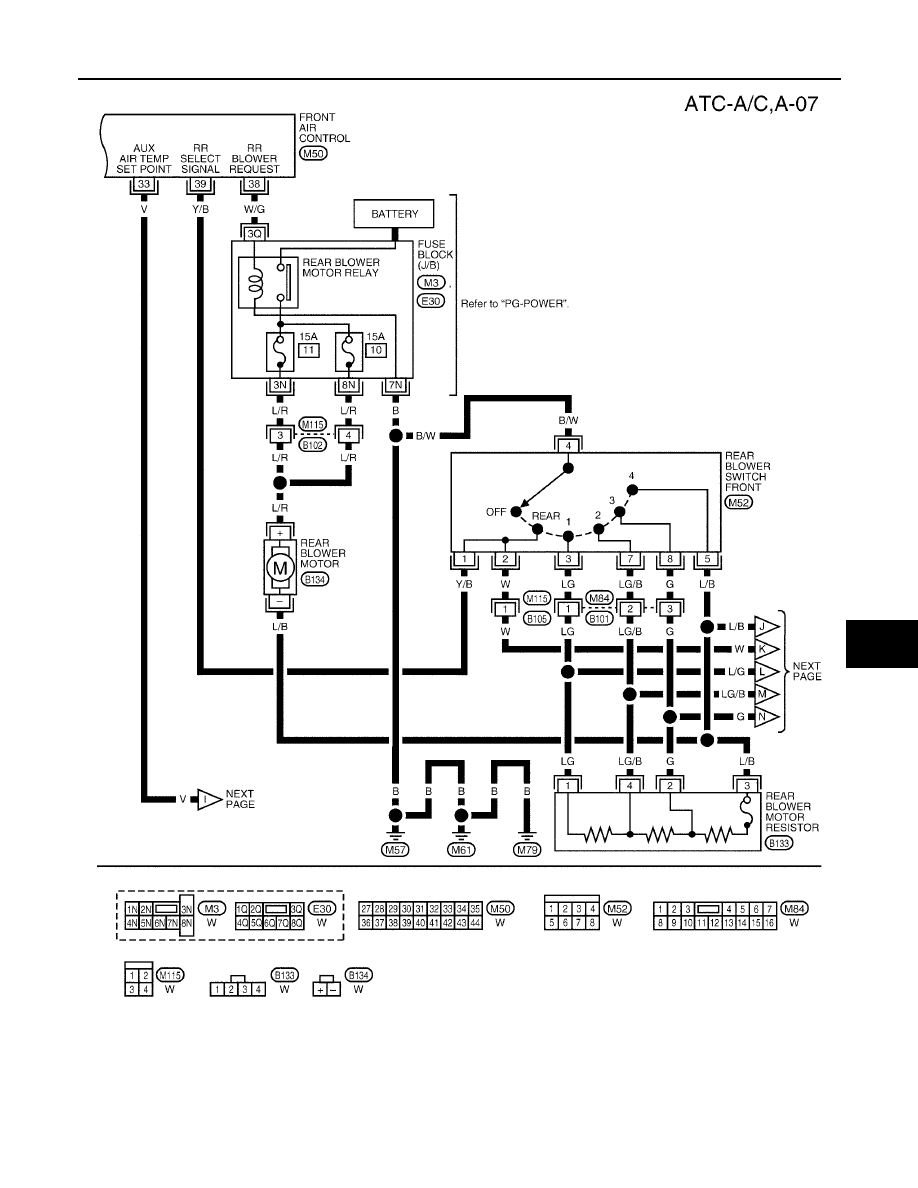
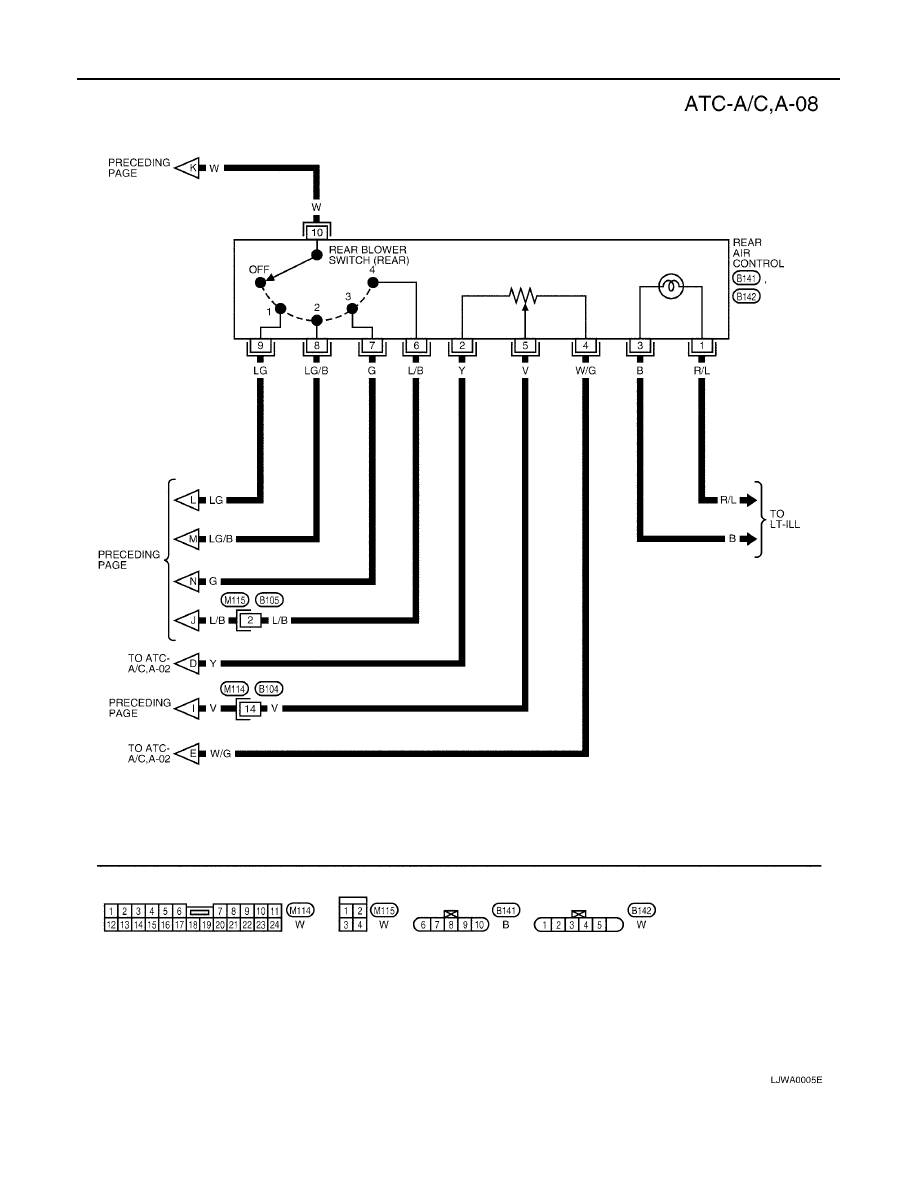
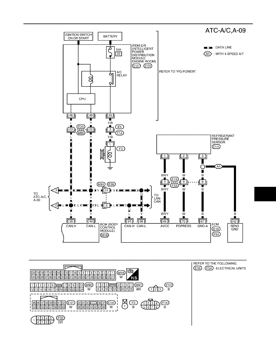
Wiring Diagram —A/C—
EJS001NG
WJWA0058E
ATC-40
TROUBLE DIAGNOSIS
Revision: May 2004
2004 Quest
WJWA0059E
TROUBLE DIAGNOSIS
ATC-41
C
D
E
F
G
H
I
K
L
M
A
B
ATC
Revision: May 2004
2004 Quest
WJWA0167E
ATC-42
TROUBLE DIAGNOSIS
Revision: May 2004
2004 Quest
WJWA0061E
TROUBLE DIAGNOSIS
ATC-43
C
D
E
F
G
H
I
K
L
M
A
B
ATC
Revision: May 2004
2004 Quest
WJWA0175E
ATC-44
TROUBLE DIAGNOSIS
Revision: May 2004
2004 Quest
LJWA0003E
TROUBLE DIAGNOSIS
ATC-45
C
D
E
F
G
H
I
K
L
M
A
B
ATC
Revision: May 2004
2004 Quest
LJWA0004E
ATC-46
TROUBLE DIAGNOSIS
Revision: May 2004
2004 Quest
LJWA0005E
TROUBLE DIAGNOSIS
ATC-47
C
D
E
F
G
H
I
K
L
M
A
B
ATC
Revision: May 2004
2004 Quest
LJWA0006E
ATC-48
TROUBLE DIAGNOSIS
Revision: May 2004
2004 Quest
Intake Front Air Control Terminals and Reference Value
EJS001NH
Measure voltage between each terminal and ground by following
Terminals and Reference Value for front air control.
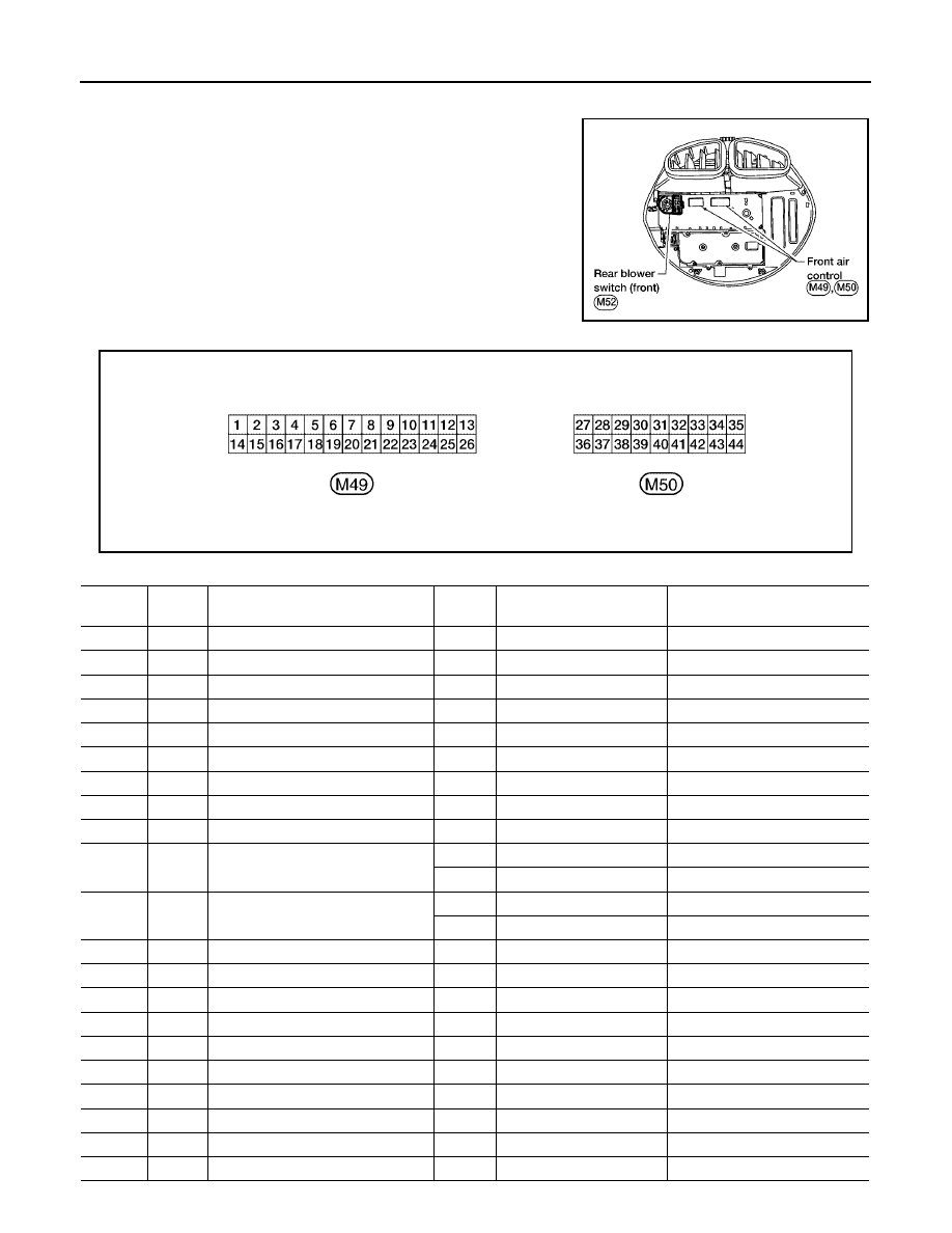
PIN CONNECTOR TERMINAL LAYOUT
TERMINALS AND REFERENCE VALUE FOR FRONT AIR CONTROL
WJIA0401E
WJIA0402E
Termi-
nal No.
Wire
Color
Item
Ignition
Switch
Condition
Voltage (V)
(Approx.)
1
B
Ground
-
-
0V
2
W/G
Sensor power
ON
-
5V
3
L/G
Air mix door motor (driver) CW
ON
Clockwise rotation
Battery voltage
4
L/B
Air mix door motor (driver) CCW
ON
Counterclockwise rotation
Battery voltage
5
SB
Mode door motor CW
ON
Clockwise rotation
Battery voltage
6
L/O
Mode door motor CCW
ON
Counterclockwise rotation
Battery voltage
7
R/B
Intake door motor (driver) CCW
ON
Clockwise rotation
Battery voltage
8
R
Intake door motor (driver) CW
ON
Counterclockwise rotation
Battery voltage
9
R/W
Intake sensor
ON
-
0 - 5V
10
L/Y
Fan ON signal
ON
Fan switch OFF
5V
ON
Fan switch ON
0V
12
L/R
Compressor ON signal
ON
A/C switch OFF
5V
ON
A/C switch ON
0V
13
O
Variable blower control
ON
-
0 - 5V
14
G/Y
Power supply for IGN
ON
-
Battery voltage
15
Y
Sensor ground
ON
-
0V
16
LG
Mode door motor feedback
ON
-
0 - 5V
17
GR/R
Ambient sensor
ON
-
0 - 5V
18
Y/B
Air mix door motor (driver) feedback
ON
-
0 - 5V
19
W/B
Defroster door motor CCW
ON
Counterclockwise rotation
Battery voltage
20
W
Defroster door motor CW
ON
Clockwise rotation
Battery voltage
21
O/B
Sensor return
ON
-
0 - 5V
22
Y/R
Power supply for BAT
-
-
Battery voltage

TROUBLE DIAGNOSIS
ATC-49
C
D
E
F
G
H
I
K
L
M
A
B
ATC
Revision: May 2004
2004 Quest
23
R/L
Illumination +
ON
Park lamps ON
Battery voltage
24
R/Y
Illumination -
-
Park lamps ON
25
G/R
Heater pump
ON
Heater pump OFF
Battery voltage
Heater pump ON
0V
26
G/B
Front blower request
ON
Front blower motor OFF
Battery voltage
Front blower motor ON
0V
27
P/L
Air mix door motor (rear) CW
ON
Clockwise rotation
Battery voltage
28
LG/R
Air mix door motor (rear) CCW
ON
Counterclockwise rotation
Battery voltage
29
P/B
Intake door motor (passenger) CCW
ON
Counterclockwise rotation
Battery voltage
30
P
Intake door motor (passenger) CW
ON
Clockwise rotation
Battery voltage
31
SB
Optical sensor (passenger)
ON
-
0 - 5V
32
BR/W
In-vehicle sensor signal
ON
-
0 - 5V
33
V
Air mix door (rear) set point
ON
-
0 - 5V
34
L
CAN-H
ON
-
0 - 5V
35
Y
CAN-L
ON
-
0 - 5V
36
G/W
Air mix door motor (passenger) CW
ON
Clockwise rotation
Battery voltage
37
Y/R
Air mix door motor (passenger)
CCW
ON
Counterclockwise rotation
Battery voltage
38
W/G
Rear blower request
ON
Front blower motor OFF
Battery voltage
Front blower motor ON
0V
39
Y/B
Rear select signal
ON
-
0V - Battery voltage
40
LG
Optical sensor (driver)
ON
-
0 - 5V
41
LG/B
Air mix door motor (passenger)
feedback
ON
-
0 - 5V
42
G/B
Air mix door motor (rear) feedback
ON
-
0 - 5V
43
BR
In-vehicle sensor motor (+)
ON
-
Battery voltage
44
W/R
In-vehicle sensor motor (-)
ON
-
0V
Termi-
nal No.
Wire
Color
Item
Ignition
Switch
Condition
Voltage (V)
(Approx.)
PIIA2344E
ATC-50
TROUBLE DIAGNOSIS
Revision: May 2004
2004 Quest
A/C System Self-diagnosis Function
EJS001NI
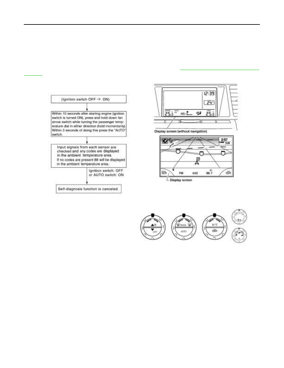
DESCRIPTION
The self-diagnostic system diagnoses sensors, door motors, blower motor, etc. Refer to applicable sections
(items) for details. Shifting from usual control to the self-diagnostic system is accomplished by turning the igni-
tion switch ON and pressing the down fan arrow switch while turning the passenger temperature dial in either
direction (hold momentarily). Within 3 seconds of doing this, press the AUTO switch. The fan bars will flash
and the ambient temperature display will indicate 0
°
during the self-diagnosis. Fault codes (if any are present)
will be displayed in the ambient temperature display area. Refer to
WJIA0403E

TROUBLE DIAGNOSIS
ATC-51
C
D
E
F
G
H
I
K
L
M
A
B
ATC
Revision: May 2004
2004 Quest
SELF-DIAGNOSIS CODE CHART
Code No.
Reference page
02
EE changed by calibration
03
Battery voltage out of range
04
Mode switch circuit open or short
05
Blower motor failure
ATC-78, "Front Blower Motor Circuit"
12
Air mix door motor (passenger) circuit failure
ATC-66, "DIAGNOSTIC PROCEDURE FOR AIR MIX DOOR
MOTOR (PASSENGER)"
21
BCM not responding to rear defroster request
22
Air mix door motor (driver) circuit failure
ATC-64, "DIAGNOSTIC PROCEDURE FOR AIR MIX DOOR
MOTOR (DRIVER)"
30
In-vehicle sensor circuit out of range (low)
ATC-120, "In-vehicle Sensor Circuit"
31
In-vehicle sensor circuit out of range (high)
34
Air mix door motor (driver) PBR circuit failure
ATC-64, "DIAGNOSTIC PROCEDURE FOR AIR MIX DOOR
MOTOR (DRIVER)"
36
Air mix door motor (passenger) PBR circuit failure
ATC-66, "DIAGNOSTIC PROCEDURE FOR AIR MIX DOOR
MOTOR (PASSENGER)"
38
Air mix door motor (rear) circuit failure
ATC-68, "DIAGNOSTIC PROCEDURE FOR AIR MIX DOOR
MOTOR (REAR)"
40
Ambient sensor circuit open
ATC-117, "Ambient Sensor Circuit"
41
Ambient sensor circuit short
44
In-vehicle sensor motor circuit open
ATC-120, "In-vehicle Sensor Circuit"
46
In-vehicle sensor motor circuit short
50
Optical sensor (driver) circuit open or short
ATC-123, "Optical Sensor Circuit"
52
Optical sensor (passenger) circuit open or short
56
Intake sensor circuit short
ATC-125, "Intake Sensor Circuit"
57
Intake sensor circuit open
62
Defroster door motor circuit failure
ATC-75, "Defroster Door Motor Circuit"
72
Intake door motor (passenger) circuit failure
ATC-73, "DIAGNOSTIC PROCEDURE FOR INTAKE DOOR
MOTOR (PASSENGER)"
80
CAN bus fault
81
CAN BCM message missing
82
Intake door motor (driver) circuit failure
ATC-73, "DIAGNOSTIC PROCEDURE FOR INTAKE DOOR
MOTOR (DRIVER)"
90
Stuck button
92
Mode door motor circuit failure
ATC-52
TROUBLE DIAGNOSIS
Revision: May 2004
2004 Quest
Operational Check
EJS001NJ
The purpose of the operational check is to confirm that the system operates properly.
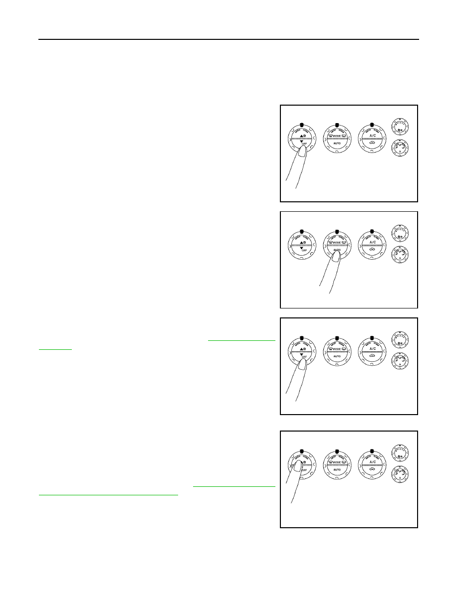
CHECKING MEMORY FUNCTION
1.
Set the temperature to 90
°
F or 32
°
C.
2.
Press OFF switch (hold fan switch down until system shuts
OFF).
3.
Turn ignition switch OFF.
4.
Turn ignition switch ON.
5.
Press the AUTO switch.
6.
Confirm that the set temperature remains at previous tempera-
ture.
7.
Press OFF switch (hold fan switch down until system shuts
OFF).
If NG, go to trouble diagnosis procedure for
.
If OK, continue with next check.
CHECKING BLOWER
1.
Press top of fan control switch. Blower should operate on low
speed. The fan symbol should have one blade lit (on display).
2.
Press top of fan control switch again, and continue checking
blower speed and fan symbol until all speeds are checked.
3.
Leave blower on MAX speed.
If NG, go to trouble diagnosis procedure for
If OK, continue with next check.
Conditions
: Engine running and at normal operating temperature
WJIA0404E
WJIA0411E
WJIA0404E
WJIA0405E
TROUBLE DIAGNOSIS
ATC-53
C
D
E
F
G
H
I
K
L
M
A
B
ATC
Revision: May 2004
2004 Quest
CHECKING DISCHARGE AIR
1.
Press MODE switch four times and rotate the DEF dial counter-
clockwise.
2.
Each position indicator should change shape (on display).
3.
Confirm that discharge air comes out according to the air distri-
bution table. Refer to
Mode door position is checked in the next step.
If NG, go to trouble diagnosis procedure for
If OK, continue with next check.
NOTE:
Confirm that the compressor clutch is engaged (sound or visual
inspection) and intake door position is at fresh when the DEF or D/F
is selected.
CHECKING RECIRCULATION
1.
Press recirculation (
) switch one time. Recirculation indica-
tor should illuminate.
2.
Press recirculation (
) switch one more time. Recirculation
indicator should go off.
3.
Listen for intake door position change (blower sound should
change slightly).
If NG, go to trouble diagnosis procedure for
If OK, continue with next check.
NOTE:
Confirm that the compressor clutch is engaged (sound or visual
inspection) and intake door position is at fresh when the DEF or D/F is selected.
CHECKING TEMPERATURE DECREASE
1.
Rotate temperature dial counterclockwise (driver side or pas-
senger side) until 18
°
C (60
°
F) is displayed.
2.
Check for cold air at appropriate discharge air outlets.
If NG, listen for sound of air mix door motor operation if OK, go to
trouble diagnosis procedure for
ATC-105, "Insufficient Cooling"
. If
air mix door motor appears to be malfunctioning, go to
"DIAGNOSTIC PROCEDURE FOR AIR MIX DOOR MOTOR
(DRIVER)"
ATC-66, "DIAGNOSTIC PROCEDURE FOR AIR MIX
.
If OK, continue with next check.
WJIA0406E
WJIA0528E
WJIA0407E
WJIA0408E
ATC-54
TROUBLE DIAGNOSIS
Revision: May 2004
2004 Quest
CHECKING TEMPERATURE INCREASE
1.
Rotate temperature dial clockwise (driver side or passenger
side) until 32
°
C (90
°
F) is displayed.
2.
Check for hot air at appropriate discharge air outlets.
If NG, listen for sound of air mix door motor operation. If OK, go to
trouble diagnosis procedure for
ATC-112, "Insufficient Heating"
. If air
mix door motor appears to be malfunctioning, go to
NOSTIC PROCEDURE FOR AIR MIX DOOR MOTOR (DRIVER)"
or
ATC-66, "DIAGNOSTIC PROCEDURE FOR AIR MIX DOOR
If OK, continue with next check.
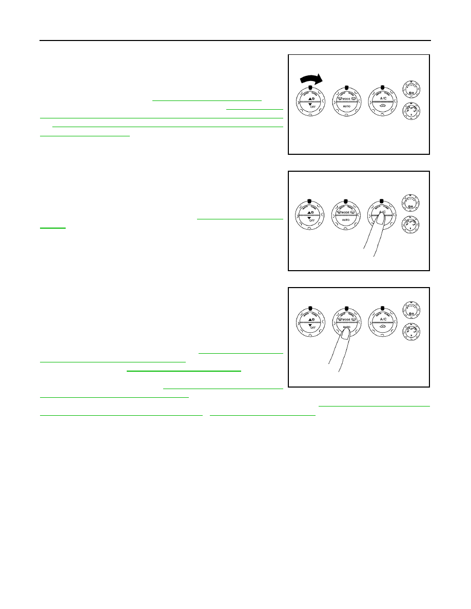
CHECK A/C SWITCH
1.
Press A/C switch when AUTO switch is ON, or in manual mode.
2.
A/C switch indicator will turn ON.
●
Confirm that the compressor clutch engages (sound or visual
inspection).
If NG, go to trouble diagnosis procedure for
If OK, continue with next check.
CHECKING AUTO MODE
1.
Press AUTO switch.
2.
Display should indicate AUTO.
●
If ambient temperatues is warm, and selected temperature is
cool, confirm that the compressor clutch engages (sound or
visual inspection). (Discharge air and blower speed will
depend on ambient, in-vehicle, and set temperatures.)
If NG, go to trouble diagnosis procedure for
and Ground Circuit for Front Air Control"
, then if necessary, trouble
ATC-99, "Magnet Clutch Circuit"
If all operational checks are OK (symptom cannot be duplicated), go
to malfunction Simulation Tests in
ATC-33, "How to Perform Trouble
Diagnosis for Quick and Accurate Repair"
lined to simulate driving conditions environment. If symptom appears. Refer to
ble Diagnosis for Quick and Accurate Repair"
and perform applicable trouble
diagnosis procedures.
WJIA0409E
WJIA0410E
WJIA0411E
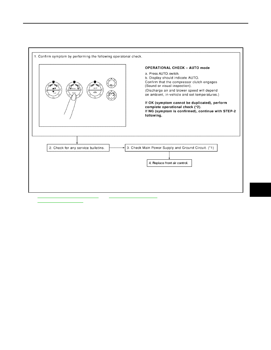
TROUBLE DIAGNOSIS
ATC-55
C
D
E
F
G
H
I
K
L
M
A
B
ATC
Revision: May 2004
2004 Quest
Power Supply and Ground Circuit for Front Air Control
EJS001NK
SYMPTOM: A/C system does not come on.
INSPECTION FLOW
*1
ATC-55, "Power Supply and Ground
Circuit for Front Air Control"
.
*2
.
WJIA1023E
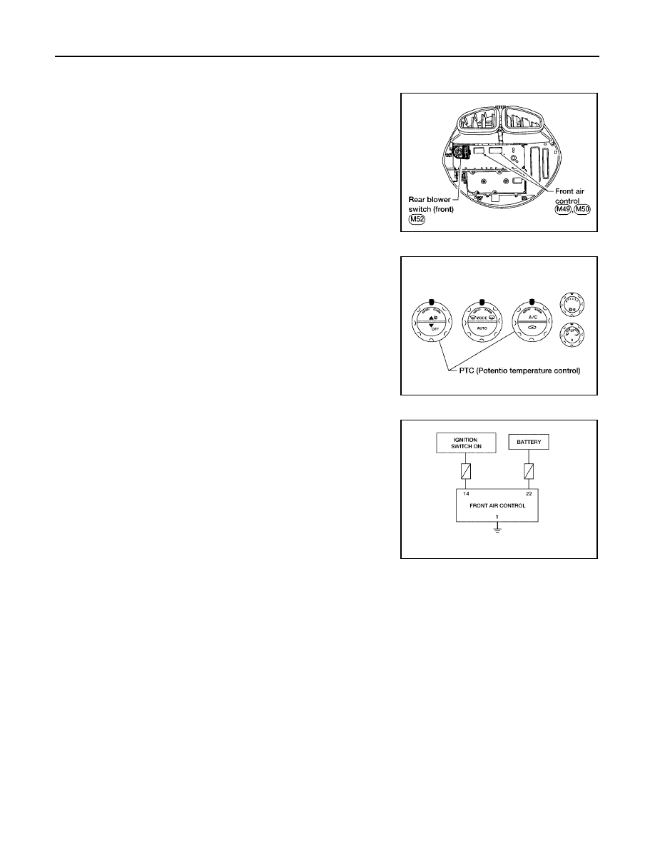
ATC-56
TROUBLE DIAGNOSIS
Revision: May 2004
2004 Quest
COMPONENT DESCRIPTION
Front Air Control
The front air control has a built-in microcomputer which processes
information sent from various sensors needed for air conditioner
operation. The air mix door motors, mode door motor, intake door
motors, defroster door motor, blower motor and compressor are then
controlled.
The front air control is unitized with control mechanisms. When the
various switches and temperature dials are operated, data is input to
the front air control.
Self-diagnostic functions are also built into the front air control to pro-
vide quick check of malfunctions in the auto air conditioner system.
Potentio Temperature Control (PTC)
There are two PTCs (passenger and driver) built into the front air
control. They can be set at an interval of 0.5
°
C (1.0
°
F) in the 18
°
C
(60
°
F) to 32
°
C (90
°
F) temperature range by rotating the temperature
dial. The set temperature is displayed.
DIAGNOSTIC PROCEDURE FOR A/C SYSTEM
SYMPTOM: A/C system does not come on.
WJIA0401E
WJIA0413E
WJIA0414E
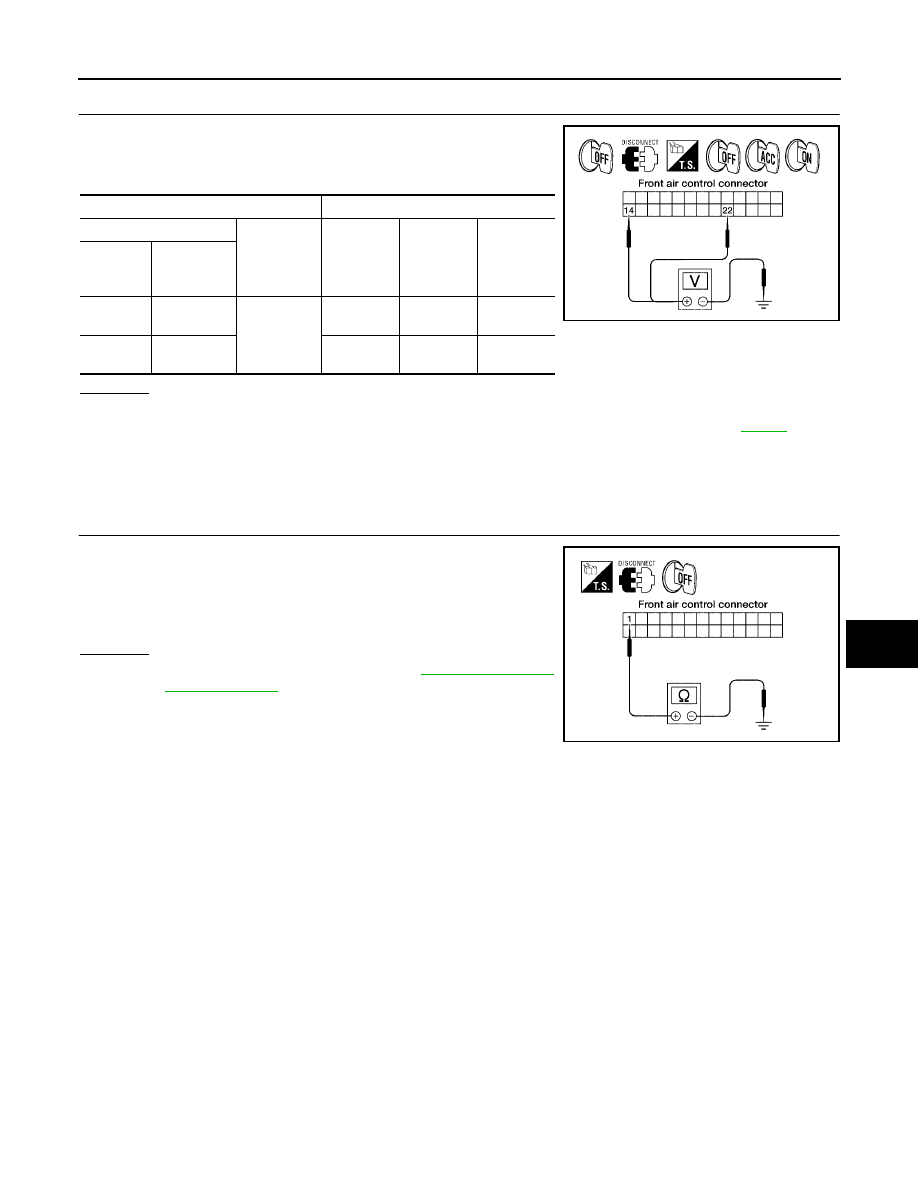
TROUBLE DIAGNOSIS
ATC-57
C
D
E
F
G
H
I
K
L
M
A
B
ATC
Revision: May 2004
2004 Quest
1.
CHECK POWER SUPPLY CIRCUITS FOR FRONT AIR CONTROL
1.
Disconnect front air control connector.
2.
Check voltage between front air control harness connector M49
terminals 14 (G/Y) and 22 (Y/R), and ground.
OK or NG
OK
>> GO TO 2.
NG
>> Check 10A and 15A fuses [Nos. 2 and 19, located in the fuse block (J/B)]. Refer to
.
●
If fuses are OK, check harness for open circuit. Repair or replace as necessary.
●
If fuses are NG, replace fuse and check harness for short circuit. Repair or replace as neces-
sary.
2.
CHECK GROUND CIRCUIT FOR FRONT AIR CONTROL
1.
Turn ignition switch OFF.
2.
Check continuity between front air control harness connector
M49 terminal 1 (B) and ground.
OK or NG
OK
>> Replace front air control. Refer to
.
NG
>> Repair harness or connector.
Terminals
Ignition switch position
(+)
(-)
OFF
ACC
ON
Front air
control
connector
Terminal No.
(Wire color)
M49
14 (G/Y)
Ground
Approx. 0V
Approx. 0V
Battery
voltage
M49
22 (Y/R)
Battery
voltage
Battery
voltage
Battery
voltage
WJIA0415E
Continuity should exist.
WJIA0416E
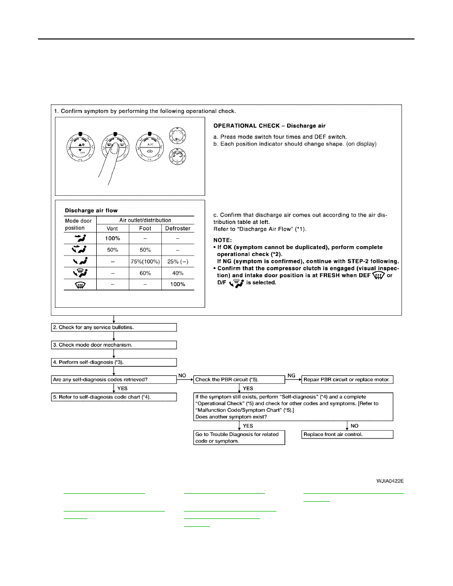
ATC-58
TROUBLE DIAGNOSIS
Revision: May 2004
2004 Quest
Mode Door Motor Circuit
EJS001NM
SYMPTOM:
●
Air outlet does not change.
●
Mode door motor does not operate normally.
INSPECTION FLOW
*1
.
*2
.
*3
ATC-50, "A/C System Self-diagnosis
Function"
*4
ATC-51, "SELF-DIAGNOSIS CODE
CHART"
*5
ATC-60, "DIAGNOSTIC PROCE-
DURE FOR MODE DOOR
MOTOR"
WJIA0422E
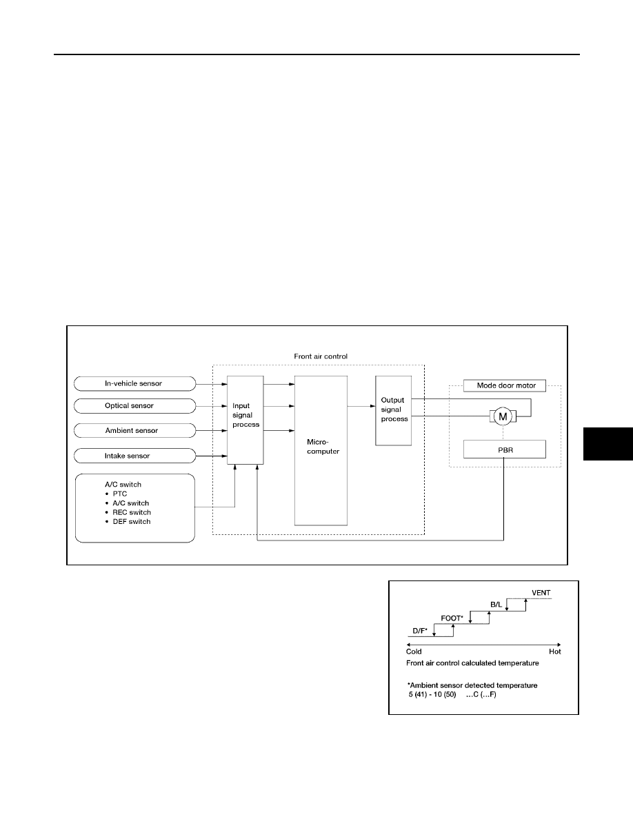
TROUBLE DIAGNOSIS
ATC-59
C
D
E
F
G
H
I
K
L
M
A
B
ATC
Revision: May 2004
2004 Quest
SYSTEM DESCRIPTION
Component Parts
Mode door control system components are:
●
Front air control
●
Mode door motor
●
PBR (built into mode door motor)
●
In-vehicle sensor
●
Ambient sensor
●
Optical sensor
●
Intake sensor
System Operation
The mode door position (vent, B/L, foot, and defrost) is set by the front air control by means of the mode door
motor. When a mode door position is selected on the front air control, voltage is applied to one circuit of the
mode door motor while ground is applied to the other circuit, causing the mode door motor to rotate. The direc-
tion of rotation is determined by which circuit has voltage applied to it, and which one has ground applied to it.
The front air control monitors the mode door position by measuring the voltage signal on the PBR circuit.
In AUTO mode the mode door position is set by the front air control which determines the proper position
based on inputs from the in-vehicle sensor, ambient sensor, optical sensor, intake sensor, and the temperature
selected by the driver or passenger.
Mode Door Control Specification
WJIA0423E
WJIA0434E
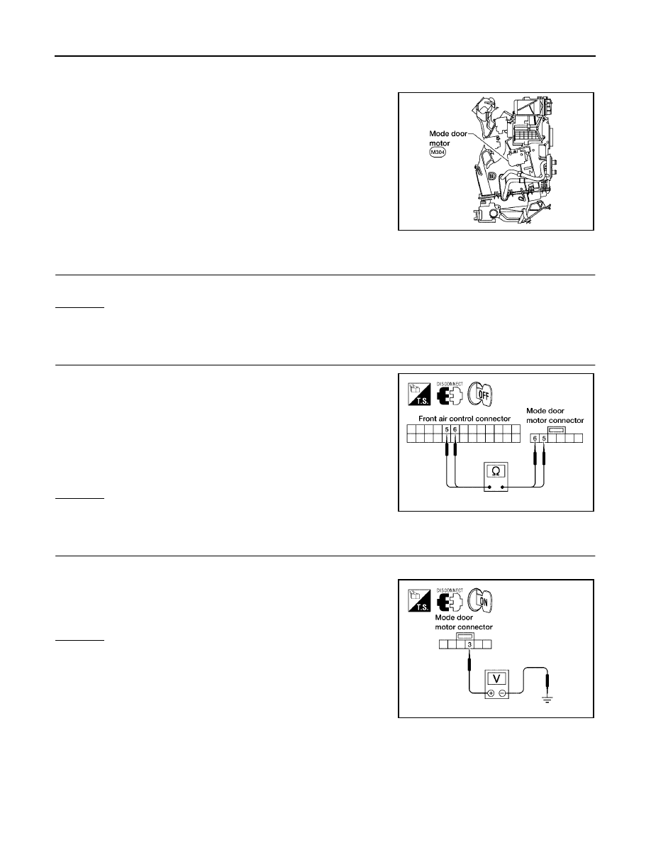
ATC-60
TROUBLE DIAGNOSIS
Revision: May 2004
2004 Quest
COMPONENT DESCRIPTION
Mode Door Motor
The mode door motor is attached to the heater & cooling unit. It
rotates so that air is discharged from the outlet as indicated by the
front air control. Motor rotation is conveyed to a link which activates
the mode door.
DIAGNOSTIC PROCEDURE FOR MODE DOOR MOTOR
1.
CHECK RESULT FROM FRONT AIR CONTROL SELF-DIAGNOSIS
Self-diagnosis code 92 is present.
Yes or No
Yes
>> GO TO 2.
No
>> GO TO 3.
2.
CHECK POWER SUPPLY AND GROUND CIRCUITS FOR MODE DOOR MOTOR
1.
Disconnect front air control connector and mode door motor
connector.
2.
Check continuity between front air control harness connector
M49 terminal 5 (SB) and mode door motor connector M304 ter-
minal 5 (SB) and between front air control harness connector
M49 terminal 6 (L/O) and mode door motor connector M304 ter-
minal 6 (L/O).
OK or NG
OK
>> Replace mode door motor.
NG
>> Repair or replace harness as necessary.
3.
CHECK PBR REFERENCE SIGNAL VOLTAGE
1.
Disconnect the mode door motor harness connector.
2.
Check voltage between mode door motor harness connector
M304 terminal 3 (W/G) and ground.
OK or NG
OK
>> GO TO 5.
NG
>> GO TO 4.
WJIA0424E
Continuity should exist.
LJIA0027E
5V (Approx.) should exist.
LJIA0028E
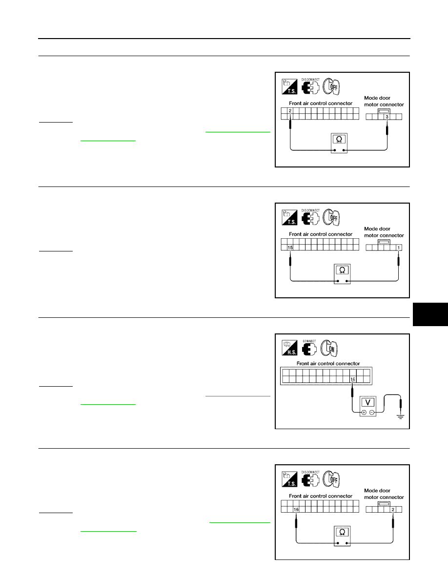
TROUBLE DIAGNOSIS
ATC-61
C
D
E
F
G
H
I
K
L
M
A
B
ATC
Revision: May 2004
2004 Quest
4.
CHECK PBR REFERENCE VOLTAGE CIRCUIT BETWEEN MODE DOOR AND FRONT AIR CONTROL
1.
Disconnect the front air control harness connector.
2.
Check continuity between mode door motor harness connector
M304 terminal 3 (W/G) and front air control harness connector
M49 terminal 2 (W/G).
OK or NG
OK
>> Replace front air control. Refer to
.
NG
>> Repair or replace harness as necessary.
5.
CHECK PBR GROUND REFERENCE CIRCUIT
1.
Disconnect the front air control harness connector.
2.
Check continuity between mode door motor harness connector
M304 terminal 1 (Y) and front air control harness connector M49
terminal 15 (Y).
OK or NG
OK
>> GO TO 6.
NG
>> Repair or replace harness as necessary.
6.
CHECK PBR FEEDBACK SIGNAL
1.
Reconnect the front air control harness connector and mode door motor connector.
2.
Check voltage between front air control harness connector M49
terminal 16 (LG) and ground.
3.
Cycle mode switch through all modes.
OK or NG
OK
>> Replace front air control. Refer to
.
NG
>> GO TO 7.
7.
CHECK PBR FEEDBACK CIRCUIT
1.
Disconnect the mode door motor harness connector and front air control harness connector.
2.
Check continuity between mode door motor harness connector
M304 terminal 2 (LG) and front air control harness connector
M49 terminal 16 (LG).
OK or NG
OK
>> Replace mode door motor. Refer to
NG
>> Repair or replace harness as necessary.
Continuity should exist.
LJIA0029E
Continuity should exist.
LJIA0031E
0V - 5V (Approx.) should exist.
LJIA0032E
Continuity should exist.
LJIA0034E
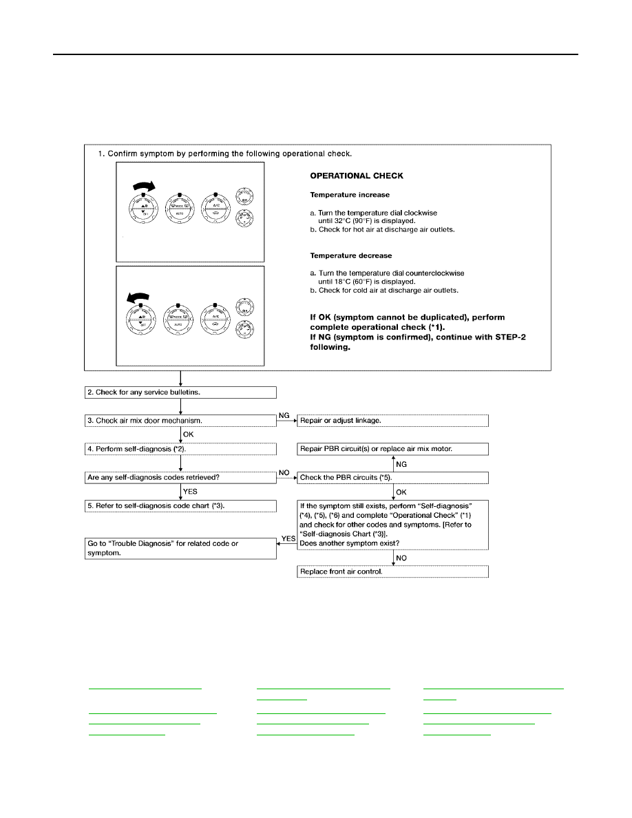
ATC-62
TROUBLE DIAGNOSIS
Revision: May 2004
2004 Quest
Air Mix Door Motor Circuit
EJS001NN
SYMPTOM:
●
Discharge air temperature does not change.
●
Air mix door motor does not operate.
INSPECTION FLOW
*1
*2
ATC-50, "A/C System Self-diagno-
sis Function"
*3
ATC-51, "SELF-DIAGNOSIS CODE
CHART"
*4
ATC-64, "DIAGNOSTIC PROCE-
DURE FOR AIR MIX DOOR
MOTOR (DRIVER)"
.
*5
ATC-66, "DIAGNOSTIC PROCE-
DURE FOR AIR MIX DOOR
MOTOR (PASSENGER)"
*6
ATC-68, "DIAGNOSTIC PROCE-
DURE FOR AIR MIX DOOR
MOTOR (REAR)"
WJIA0426E
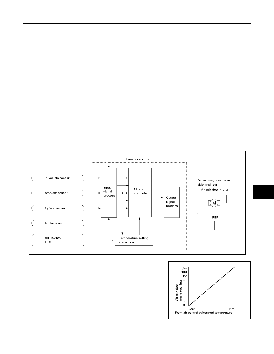
TROUBLE DIAGNOSIS
ATC-63
C
D
E
F
G
H
I
K
L
M
A
B
ATC
Revision: May 2004
2004 Quest
SYSTEM DESCRIPTION
Component Parts
Air mix door control system components are:
●
Front air control.
●
Air mix door motors (driver, passenger, and rear)
●
PBR (built-into air mix motors)
●
In-vehicle sensor
●
Ambient sensor
●
Optical sensor
●
Intake sensor
System Operation
The front air control receives data from the temperature selected by the driver and front and rear passengers.
The front air control then applies a voltage to one circuit of the appropriate air mix door motor, while ground is
applied to the other circuit, causing the appropriate air mix door motor to rotate. The direction of rotation is
determined by which circuit has voltage applied to it, and which one has ground applied to it. The front air con-
trol monitors the air mix door positions by measuring the voltage signal on the PBR circuits of each door.
In AUTO mode the air mix, intake, mode door, and defrost door positions are set by the front air control which
determines the proper position based on inputs from the in-vehicle sensor, ambient sensor, optical sensor,
intake sensor, and the temperature selected by the driver and front and rear passengers.
Subsequently, HOT/COLD or DEFROST/VENT or FRESH/RECIRCULATION operation is selected. The new
door position data is returned to the front air control.
Air Mix Door Control Specification
WJIA0427E
WJIA0435E
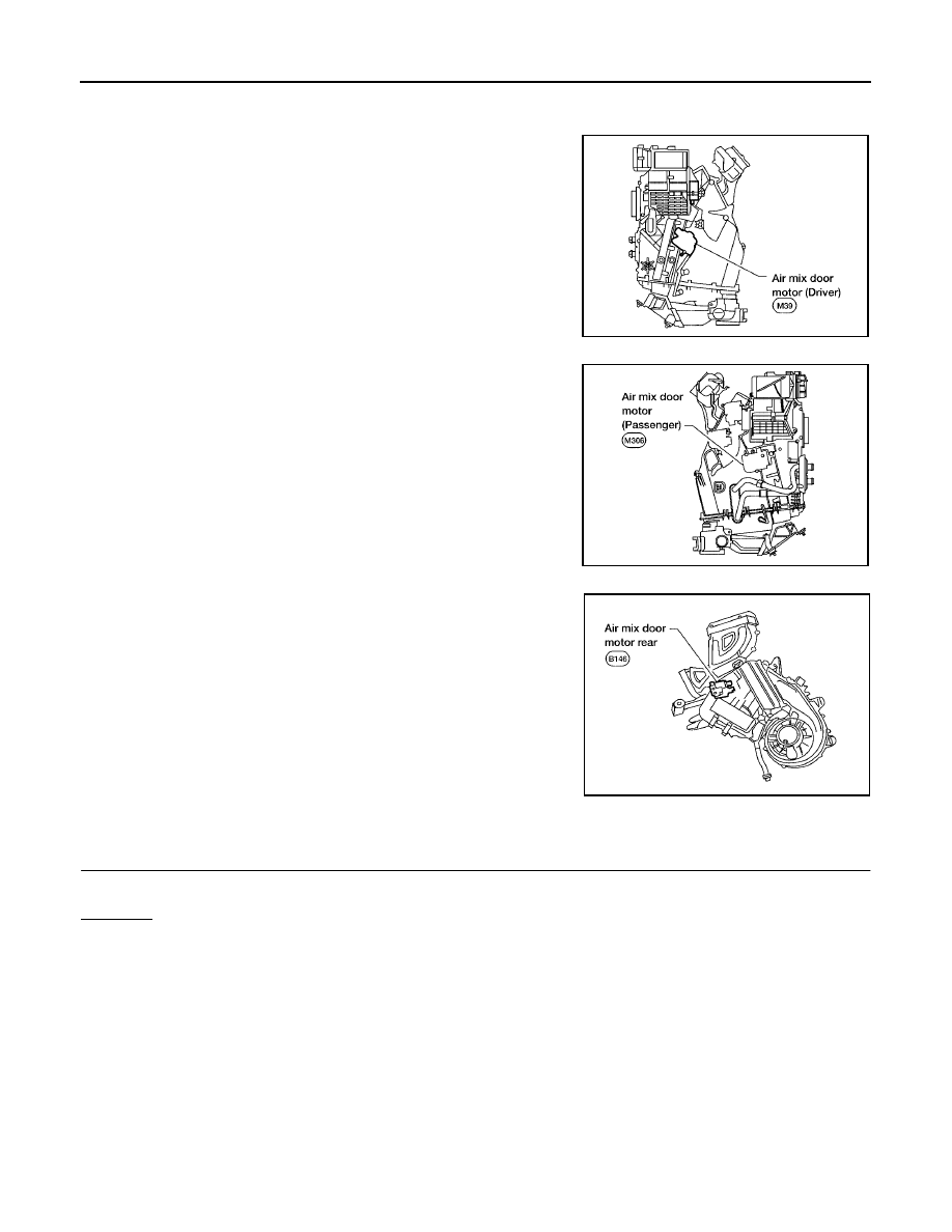
ATC-64
TROUBLE DIAGNOSIS
Revision: May 2004
2004 Quest
COMPONENT DESCRIPTION
Air Mix Door Motors
The driver and front passenger air mix door motors are attached to
the front heater & cooling unit. The rear air mix door motor is
attached to the rear heater & cooling unit. These motors rotate so
that the air mix door is opened or closed to a position set by the front
(or rear) air control. Motor rotation is then conveyed through a shaft
and the air mix door position is then fed back to the front air control
by the PBR built into the air mix door motors.
DIAGNOSTIC PROCEDURE FOR AIR MIX DOOR MOTOR (DRIVER)
1.
CHECK RESULT FROM FRONT AIR CONTROL SELF-DIAGNOSIS
Self-diagnosis code 22 is present.
Yes or No
Yes
>> GO TO 2.
No
>> GO TO 3.
WJIA0428E
WJIA0429E
WJIA0430E
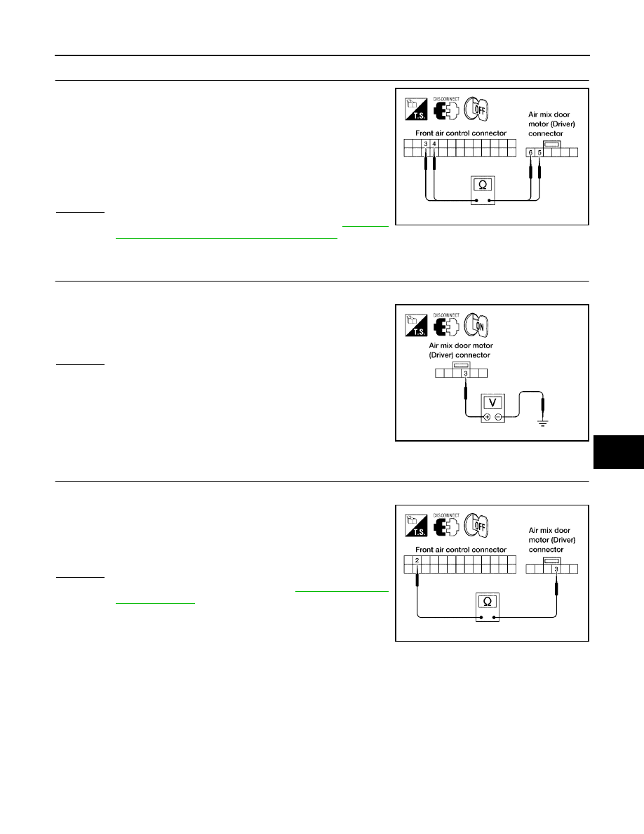
TROUBLE DIAGNOSIS
ATC-65
C
D
E
F
G
H
I
K
L
M
A
B
ATC
Revision: May 2004
2004 Quest
2.
CHECK POWER SUPPLY CIRCUITS FOR AIR MIX DOOR MOTOR (DRIVER)
1.
Disconnect front air control connector and air mix door motor
(Driver) connector.
2.
Check continuity between front air control harness connector
M49 terminal 3 (L/G) and air mix door motor (driver) connector
M39 terminal 5 (L/G) and between front air control harness con-
nector M49 terminal 4 (L/B) and air mix door motor (driver) con-
nector M39 terminal 6 (L/B).
OK or NG
OK
>> Replace air mix door motor (driver). Refer to
"FRONT AIR MIX DOOR MOTOR (DRIVER)"
NG
>> Repair or replace harness as necessary.
3.
CHECK PBR REFERENCE SIGNAL VOLTAGE
1.
Disconnect the air mix door motor (driver) harness connector.
2.
Check voltage between air mix door motor (driver) harness con-
nector M39 terminal 3 (W/G) and ground.
OK or NG
OK
>> GO TO 5.
NG
>> GO TO 4.
4.
CHECK PBR REFERENCE VOLTAGE CIRCUIT BETWEEN AIR MIX DOOR MOTOR (DRIVER) AND
FRONT AIR CONTROL
1.
Disconnect the front air control harness connector.
2.
Check continuity between air mix door motor (driver) harness
connector M39 terminal 3 (W/G) and front air control harness
connector M49 terminal 2 (W/G).
OK or NG
OK
>> Replace front air control. Refer to
.
NG
>> Repair or replace harness as necessary.
Continuity should exist.
LJIA0037E
5V (Approx.) should exist.
LJIA0038E
Continuity should exist.
LJIA0039E
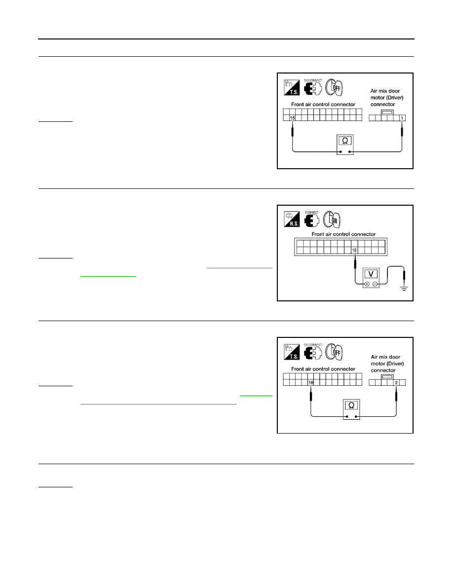
ATC-66
TROUBLE DIAGNOSIS
Revision: May 2004
2004 Quest
5.
CHECK PBR GROUND REFERENCE CIRCUIT
1.
Disconnect the front air control harness connector.
2.
Check continuity between air mix door motor (driver) harness
connector M39 terminal 1 (Y) and front air control harness con-
nector M49 terminal 15 (Y).
OK or NG
OK
>> GO TO 6.
NG
>> Repair or replace harness as necessary.
6.
CHECK PBR FEEDBACK SIGNAL
1.
Reconnect the front air control harness connector and air mix door motor (driver) harness connector.
2.
Check voltage between front air control harness connector M49
terminal 18 (Y/B) and ground.
3.
Rotate driver temperature dial through complete range.
OK or NG
OK
>> Replace front air control. Refer to
.
NG
>> GO TO 7.
7.
CHECK PBR FEEDBACK CIRCUIT
1.
Disconnect the air mix door motor (driver) harness connector and front air control harness connector.
2.
Check continuity between air mix door motor (driver) harness
connector M39 terminal 2 (Y/B) and front air control harness
connector M49 terminal 18 (Y/B).
OK or NG
OK
>> Replace air mix door motor (driver). Refer to
"FRONT AIR MIX DOOR MOTOR (DRIVER)"
NG
>> Repair or replace harness as necessary.
DIAGNOSTIC PROCEDURE FOR AIR MIX DOOR MOTOR (PASSENGER)
1.
CHECK RESULT FROM FRONT AIR CONTROL SELF-DIAGNOSIS
Self-diagnosis code 12 is present.
Yes or No
Yes
>> GO TO 2.
No
>> GO TO 3.
Continuity should exist.
LJIA0040E
0V - 5V (Approx.) should exist.
LJIA0041E
Continuity should exist.
LJIA0042E
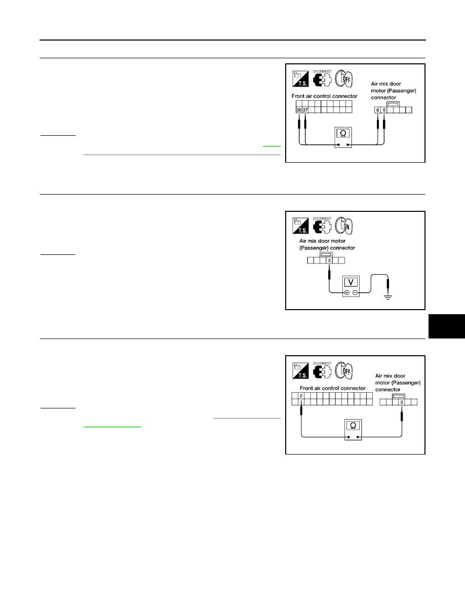
TROUBLE DIAGNOSIS
ATC-67
C
D
E
F
G
H
I
K
L
M
A
B
ATC
Revision: May 2004
2004 Quest
2.
CHECK POWER SUPPLY CIRCUIT FOR AIR MIX DOOR MOTOR (PASSENGER)
1.
Disconnect front air control connector and air mix door motor
(passenger) harness connector.
2.
Check continuity between front air control harness connector
M50 terminal 36 (G/W) and 37 (Y/R) and air mix door motor
(passenger) connector M306 terminal 5 (G/W) and 6 (Y/R).
OK or NG
OK
>> Replace air mix door motor (passenger). Refer to
150, "FRONT AIR MIX DOOR MOTOR (PASSENGER)"
.
NG
>> Repair or replace harness as necessary.
3.
CHECK PBR REFERENCE SIGNAL VOLTAGE
1.
Disconnect the air mix door motor (passenger) harness connector.
2.
Check voltage between air mix door motor (passenger) harness
connector M306 terminal 3 (L/R) and ground.
OK or NG
OK
>> GO TO 5.
NG
>> GO TO 4.
4.
CHECK PBR REFERENCE VOLTAGE CIRCUIT BETWEEN AIR MIX DOOR (PASSENGER) AND
FRONT AIR CONTROL
1.
Disconnect the front air control harness connector.
2.
Check continuity between air mix door motor (passenger) har-
ness connector M306 terminal 3 (L/R) and front air control har-
ness connector M49 terminal 2 (W/G).
OK or NG
OK
>> Replace front air control. Refer to
.
NG
>> Repair or replace harness as necessary.
Continuity should exist.
LJIA0043E
5V (Approx.) should exist.
LJIA0044E
Continuity should exist.
LJIA0045E
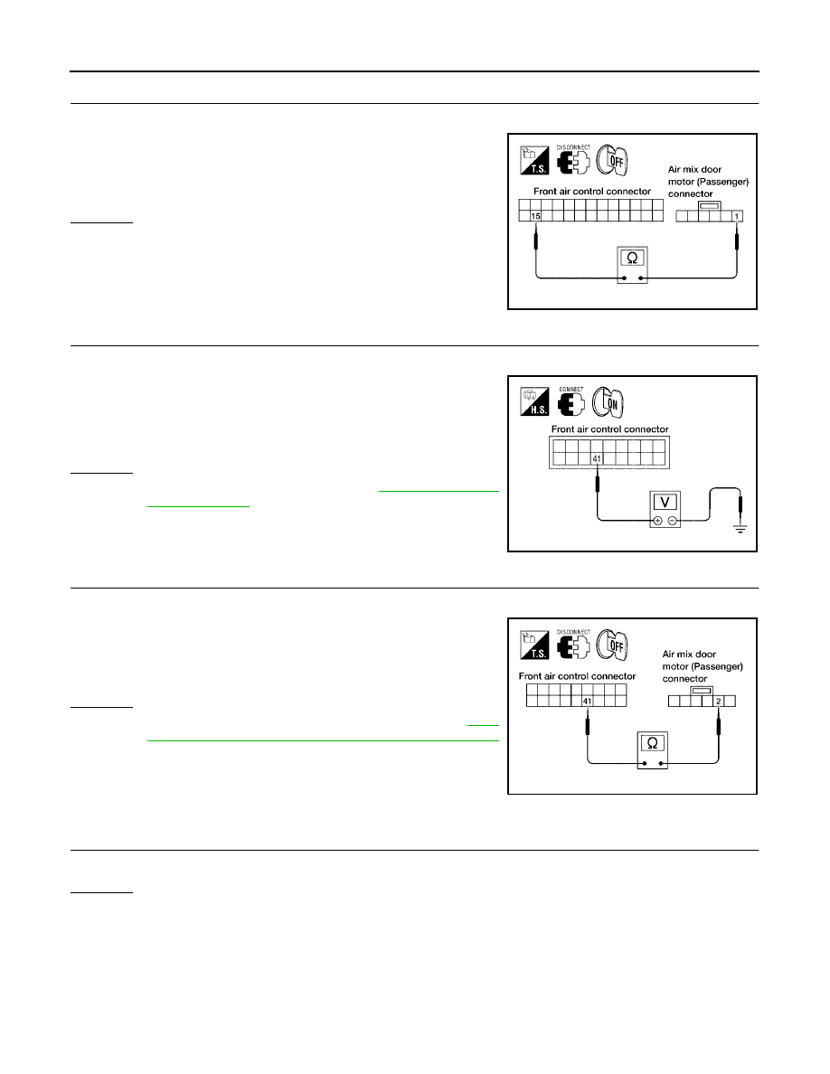
ATC-68
TROUBLE DIAGNOSIS
Revision: May 2004
2004 Quest
5.
CHECK PBR GROUND REFERENCE CIRCUIT
1.
Disconnect the front air control harness connector.
2.
Check continuity between air mix door motor (passenger) har-
ness connector M306 terminal 1 (Y) and front air control harness
connector M49 terminal 15 (Y).
OK or NG
OK
>> GO TO 6.
NG
>> Repair or replace harness as necessary.
6.
CHECK PBR FEEDBACK SIGNAL
1.
Reconnect the front air control harness connector and air mix door motor (passenger) connector.
2.
Check voltage between front air control (passenger) harness
connector M50 terminal 41 (LG/B) and ground.
3.
Rotate passenger temperature dial through complete range.
OK or NG
OK
>> Replace front air control. Refer to
.
NG
>> GO TO 7.
7.
CHECK PBR FEEDBACK CIRCUIT
1.
Disconnect the air mix door motor (passenger) harness connector and front air control harness connector.
2.
Check continuity between air mix door motor (passenger) har-
ness connector M306 terminal 2 (LG/B) and front air control har-
ness connector M50 terminal 41 (LG/B).
OK or NG
OK
>> Replace air mix door motor (passenger). Refer to
150, "FRONT AIR MIX DOOR MOTOR (PASSENGER)"
.
NG
>> Repair or replace harness as necessary.
DIAGNOSTIC PROCEDURE FOR AIR MIX DOOR MOTOR (REAR)
1.
CHECK RESULT FROM FRONT AIR CONTROL SELF-DIAGNOSIS
Self-diagnosis code 38 is present.
Yes or No
Yes
>> GO TO 2.
No
>> GO TO 3.
Continuity should exist.
LJIA0046E
0V - 5V (Approx.) should exist.
LJIA0047E
Continuity should exist.
LJIA0048E
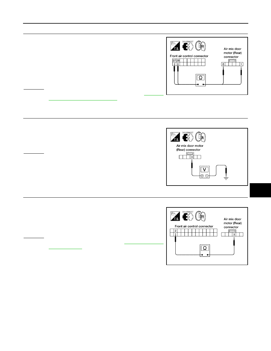
TROUBLE DIAGNOSIS
ATC-69
C
D
E
F
G
H
I
K
L
M
A
B
ATC
Revision: May 2004
2004 Quest
2.
CHECK POWER SUPPLY CIRCUIT FOR AIR MIX DOOR MOTOR (REAR)
1.
Disconnect front air control connector and air mix door motor
(rear) connector.
2.
Check continuity between front air control harness connector
M50 terminal 27 (P/L) and air mix door motor (rear) connector
B146 terminal 1 (P/L) and between front air control harness con-
nector M50 terminal 28 (LG/R) and air mix door motor (rear)
connector B146 terminal 6 (LG/R).
OK or NG
OK
>> Replace air mix door motor (rear). Refer to
.
NG
>> Repair or replace harness as necessary.
3.
CHECK PBR REFERENCE SIGNAL VOLTAGE
1.
Disconnect the air mix door motor (rear) harness connector.
2.
Check voltage between air mix door motor (rear) harness con-
nector B146 terminal 3 (W/G) and ground.
OK or NG
OK
>> GO TO 5.
NG
>> GO TO 4.
4.
CHECK PBR REFERENCE VOLTAGE CIRCUIT BETWEEN MODE DOOR AND FRONT AIR CONTROL
1.
Disconnect the front air control harness connector.
2.
Check continuity between air mix door motor (rear) harness con-
nector B146 terminal 3 (W/G) and front air control harness con-
nector M49 terminal 2 (W/G).
OK or NG
OK
>> Replace front air control. Refer to
.
NG
>> Repair or replace harness as necessary.
Continuity should exist.
LJIA0049E
5V (Approx.) should exist.
LJIA0050E
Continuity should exist.
LJIA0051E
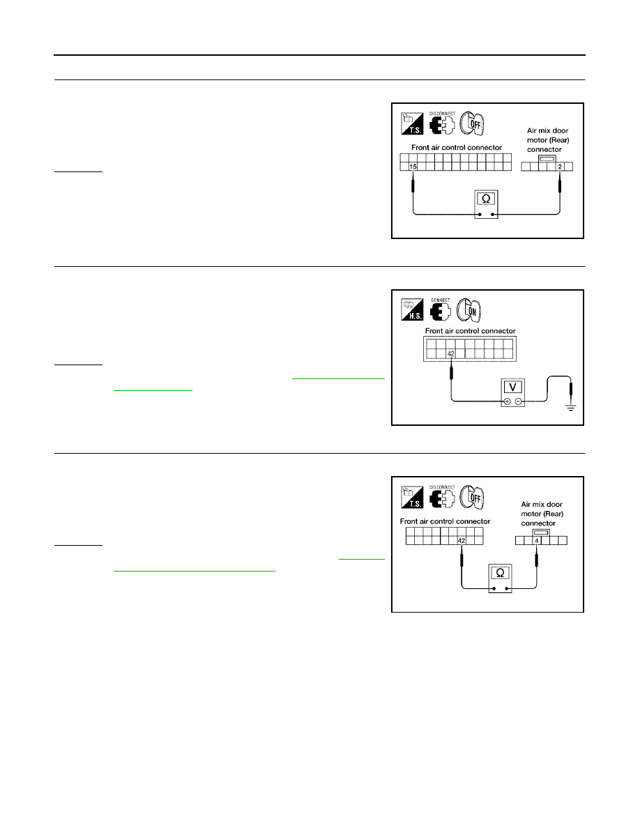
ATC-70
TROUBLE DIAGNOSIS
Revision: May 2004
2004 Quest
5.
CHECK PBR GROUND REFERENCE CIRCUIT
1.
Disconnect the front air control harness connector.
2.
Check continuity between air mix door motor (rear) harness con-
nector B146 terminal 2 (Y) and front air control harness connec-
tor M49 terminal 15 (Y).
OK or NG
OK
>> GO TO 6.
NG
>> Repair or replace harness as necessary.
6.
CHECK PBR FEEDBACK SIGNAL
1.
Reconnect the front air control harness connector and mode door motor connector.
2.
Check voltage between front air control harness connector M50
terminal 42 (G/B) and ground.
3.
Rotate rear temperature dial through complete range.
OK or NG
OK
>> Replace front air control. Refer to
.
NG
>> GO TO 7.
7.
CHECK PBR FEEDBACK CIRCUIT
1.
Disconnect the air mix door motor (rear) harness connector and front air control harness connector.
2.
Check continuity between air mix door motor (rear) harness con-
nector B146 terminal 4 (G/B) and front air control harness con-
nector M50 terminal 42 (G/B).
OK or NG
OK
>> Replace air mix door motor (rear). Refer to
NG
>> Repair or replace harness as necessary.
Continuity should exist.
LJIA0052E
0V - 5V (Approx.) should exist.
LJIA0053E
Continuity should exist.
LJIA0054E
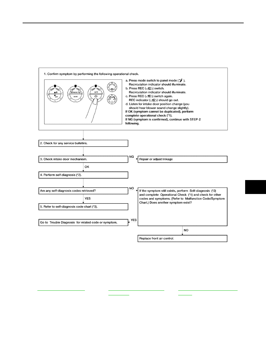
TROUBLE DIAGNOSIS
ATC-71
C
D
E
F
G
H
I
K
L
M
A
B
ATC
Revision: May 2004
2004 Quest
Intake Door Motor Circuit
EJS001NP
SYMPTOM:
●
Intake door does not change.
●
Intake door motor does not operate normally.
INSPECTION FLOW
*1
.
*2
ATC-50, "A/C System Self-diagno-
sis Function"
*3
ATC-51, "SELF-DIAGNOSIS CODE
CHART"
WJIA0431E
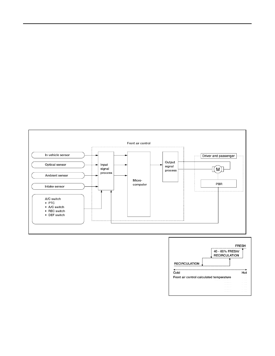
ATC-72
TROUBLE DIAGNOSIS
Revision: May 2004
2004 Quest
SYSTEM DESCRIPTION
Component Parts
Intake door control system components are:
●
Front air control
●
Intake door motor (driver and passenger)
●
In-vehicle sensor
●
Ambient sensor
●
Optical sensor
●
Intake sensor
System Operation
The intake door control determines the intake door (driver and passenger) positions based on the position of
the recirculation switch. When the recirculation switch is depressed the intake door motors rotate closing off
the fresh air inlet and recirculating the cabin air. If the recirculation switch is depressed again, the intake door
motors rotate in the opposite direction, again allowing fresh air into the cabin.
In the AUTO mode, the front air control determines the intake doors positions based on the ambient tempera-
ture, the intake air temperature and the in-vehicle temperature. When the DEFROST, or OFF switches are
pushed or A/C switch is OFF, the front air control sets the intake doors at the fresh position.
Intake Doors Control Specification
WJIA0432E
WJIA0436E
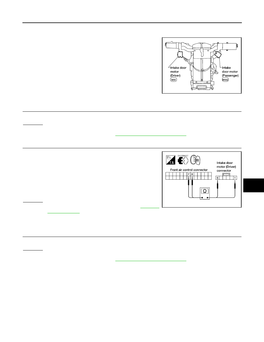
TROUBLE DIAGNOSIS
ATC-73
C
D
E
F
G
H
I
K
L
M
A
B
ATC
Revision: May 2004
2004 Quest
COMPONENT DESCRIPTION
Intake door motors
The driver and passenger intake door motors are attached to the
intake unit. They rotate so that air is drawn from inlets set by the front
air control. Motor rotation is conveyed to a lever which activates the
intake door.
DIAGNOSTIC PROCEDURE FOR INTAKE DOOR MOTOR (DRIVER)
1.
CHECK RESULT FROM FRONT AIR CONTROL SELF-DIAGNOSIS
Self-diagnosis code 82 is present.
Yes or No
Yes
>> GO TO 2.
No
>> Replace front air control. Refer to
.
2.
CHECK POWER SUPPLY CIRCUIT FOR INTAKE DOOR MOTOR (DRIVER)
1.
Disconnect front air control connector and intake door motor
(driver) connector.
2.
Check continuity between front air control harness connector
M49 terminal 7 (R/B) and intake door motor (driver) connector
M58 terminal 1 (R/B) and between front air control harness con-
nector M49 terminal 8 (R) and intake door motor (driver) con-
nector M58 terminal 6 (R).
OK or NG
OK
>> Replace intake door motor (driver). Refer to
.
NG
>> Repair or replace harness as necessary.
DIAGNOSTIC PROCEDURE FOR INTAKE DOOR MOTOR (PASSENGER)
1.
CHECK RESULT FROM FRONT AIR CONTROL SELF-DIAGNOSIS
Self-diagnosis code 72 is present.
Yes or No
Yes
>> GO TO 2.
No
>> Replace front air control. Refer to
.
WJIA0433E
Continuity should exist.
LJIA0060E
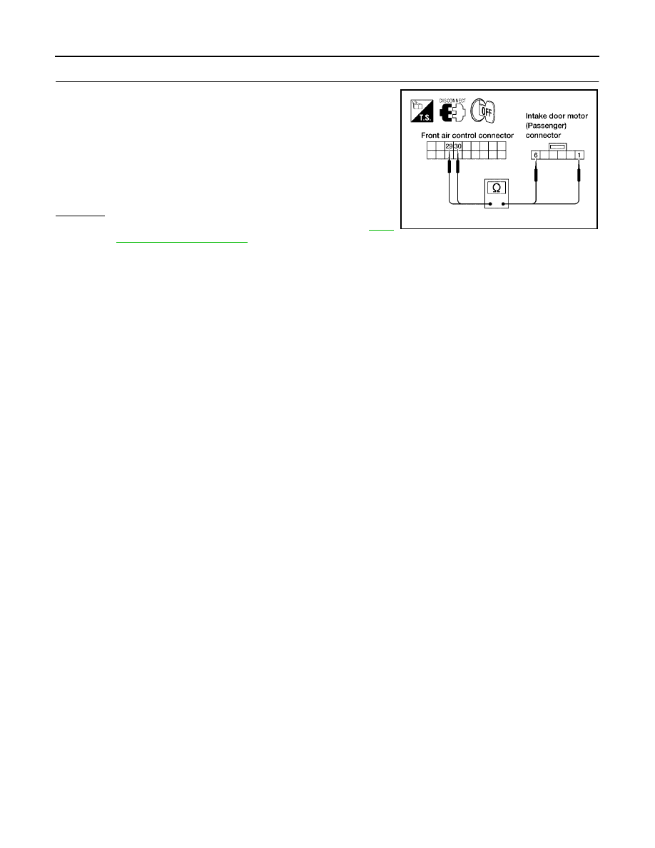
ATC-74
TROUBLE DIAGNOSIS
Revision: May 2004
2004 Quest
2.
CHECK POWER SUPPLY CIRCUIT FOR INTAKE DOOR MOTOR (PASSENGER)
1.
Disconnect front air control connector and intake door motor
(passenger) connector.
2.
Check continuity between front air control harness connector
M50 terminal 29 (P/B) and intake door motor (passenger) con-
nector M302 terminal 1 (P/W) and between front air control har-
ness connector M50 terminal 30 (P) and intake door motor
(passenger) connector M302 terminal 6 (P).
OK or NG
OK
>> Replace intake door motor (passenger). Refer to
NG
>> Repair or replace harness as necessary.
Continuity should exist.
LJIA0061E
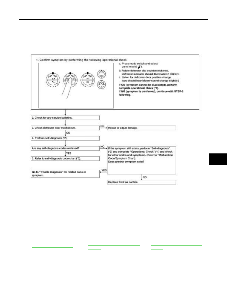
TROUBLE DIAGNOSIS
ATC-75
C
D
E
F
G
H
I
K
L
M
A
B
ATC
Revision: May 2004
2004 Quest
Defroster Door Motor Circuit
EJS001R0
SYMPTOM:
●
Defroster door does not change.
●
Defroster door does not operate normally.
INSPECTION FLOW
*1
*2
ATC-50, "A/C System Self-diagnosis
Function"
*3
ATC-51, "SELF-DIAGNOSIS CODE
CHART"
LJIA0062E
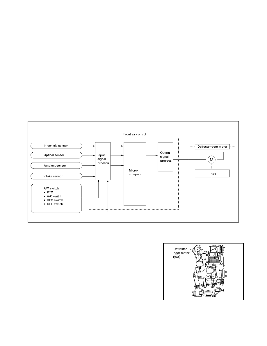
ATC-76
TROUBLE DIAGNOSIS
Revision: May 2004
2004 Quest
SYSTEM DESCRIPTION
Component Parts
Defroster door control system components are:
●
Front air control
●
Defroster door motor
●
In-vehicle sensor
●
Ambient sensor
●
Optical sensor
●
Intake sensor
System Operation
The front air control determines defroster door position based on the position of the defroster switch. When the
defroster switch is depressed, the defroster door motor rotates directing air to the defroster ducts. When any
mode other than defroster is selected, the defroster motor rotates in the opposite direction closing off air flow
to the defroster ducts.
In the AUTO mode, the front air control determines defroster door position based on the ambient temperature,
the intake air temperature and the in-vehicle temperature.
COMPONENT DESCRIPTION
Defroster door motor
The defroster door motor is attached to the front heater & cooling
unit. The front air control sends a voltage to rotate to the defroster
door directing the air flow either to the defroster ducts, or to the floor
ducts, depending on which way the voltage and ground are applied
to the motor leads. Motor rotation is conveyed to a lever which acti-
vates the defroster door.
WJIA0438E
LJIA0063E
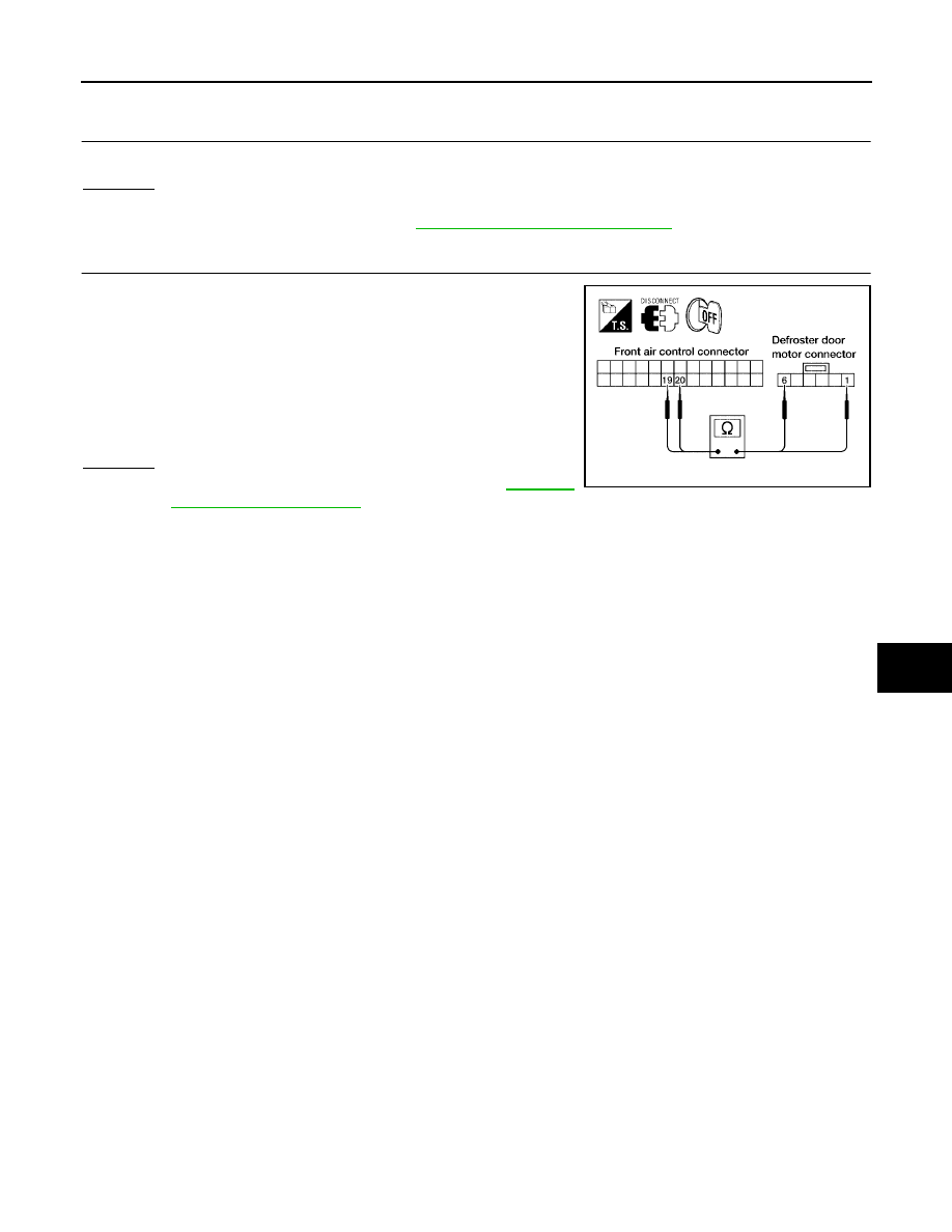
TROUBLE DIAGNOSIS
ATC-77
C
D
E
F
G
H
I
K
L
M
A
B
ATC
Revision: May 2004
2004 Quest
DIAGNOSTIC PROCEDURE FOR DEFROSTER DOOR MOTOR
1.
CHECK RESULT FROM FRONT AIR CONTROL SELF-DIAGNOSIS
Self-diagnosis code 62 is present.
OK or NG
OK
>> GO TO 2.
NG
>> Replace front air control. Refer to
.
2.
CHECK POWER SUPPLY CIRCUITS FOR DEFROSTER DOOR MOTOR
1.
Disconnect front air control connector and defroster door motor
connector.
2.
Check continuity between front air control harness connector
M49 terminal 19 (W/B) and defroster door motor connector
M303 terminal 1 (W/B) and between front air control harness
connector M49 terminal 20 (W) and defroster door motor con-
nector M303 terminal 6 (W).
OK or NG
OK
>> Replace defroster door motor. Refer to
.
NG
>> Repair or replace harness as necessary.
Continuity should exist.
LJIA0064E
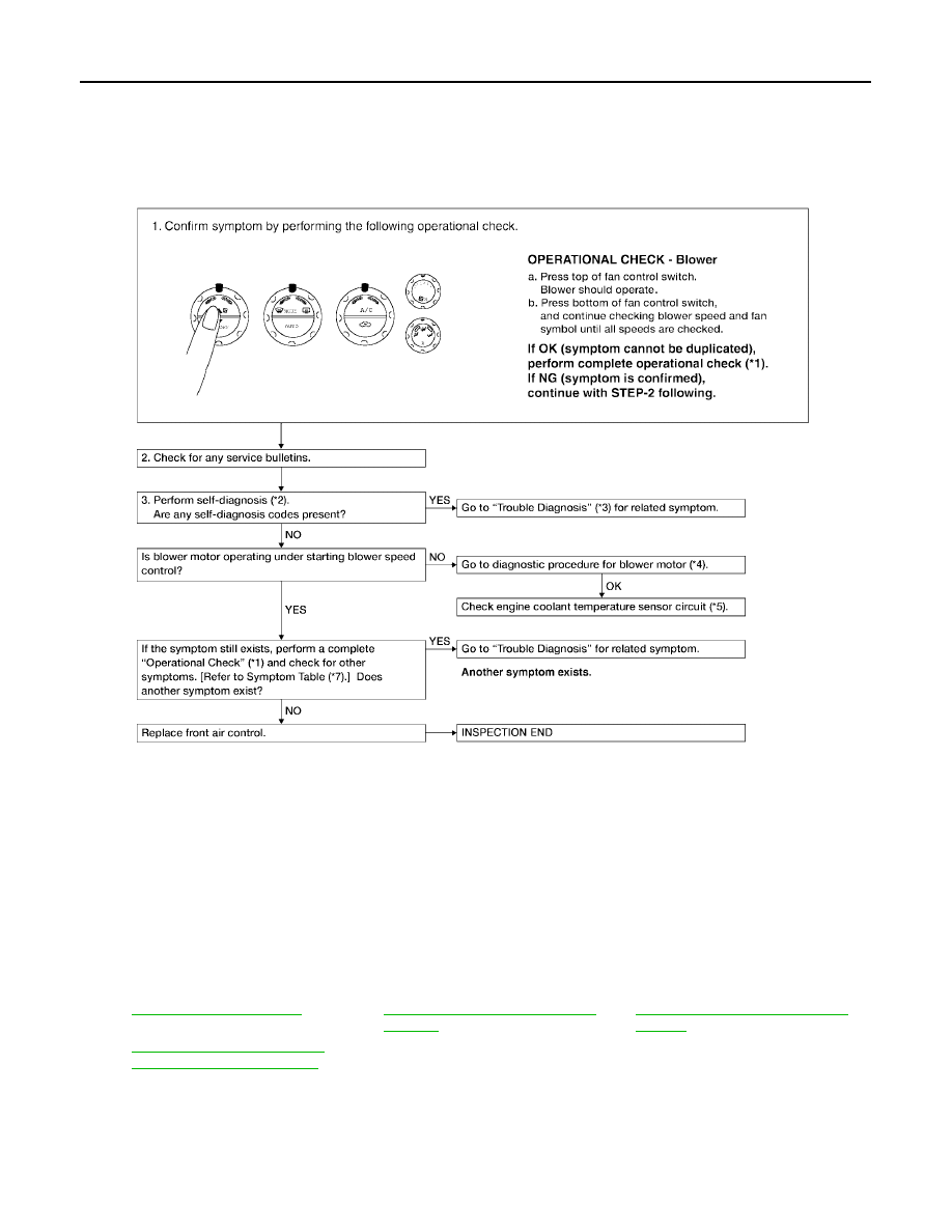
ATC-78
TROUBLE DIAGNOSIS
Revision: May 2004
2004 Quest
Front Blower Motor Circuit
EJS001QZ
SYMPTOM:
●
Blower motor operation is malfunctioning.
INSPECTION FLOW
*1
*2
ATC-50, "A/C System Self-diagnosis
Function"
.
*3
ATC-51, "SELF-DIAGNOSIS CODE
CHART"
*4
ATC-80, "DIAGNOSTIC PROCE-
DURE FOR BLOWER MOTOR"
.
WJIA0439E
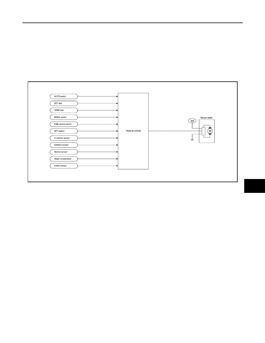
TROUBLE DIAGNOSIS
ATC-79
C
D
E
F
G
H
I
K
L
M
A
B
ATC
Revision: May 2004
2004 Quest
SYSTEM DESCRIPTION
Component Parts
Fan speed control system components are:
●
Front air control
●
In-vehicle sensor
●
Ambient sensor
●
Optical sensor
●
Intake sensor
System Operation
Automatic Mode
In the automatic mode, the blower motor speed is calculated by the front air control and variable blower control
based on input from the in-vehicle sensor, optical sensor, intake sensor and ambient sensor, and potentio tem-
perature control (PTC).
When the air flow is increased, the duty ratio of the blower fan motor
′
s drive signal is changed at 8%/sec. to
prevent a sudden increase in air flow.
In addition to manual air flow control and the usual automatic air flow control, starting air flow control, low
water temperature starting control and high passenger compartment temperature starting control are avail-
able.
Starting Fan Speed Control
Start up from cold soak condition (Automatic mode).
In a cold start up condition where the engine coolant temperature is below 50
°
C (122
°
F), the blower will not
operate at blower speed 1 for a short period of time (up to 210 seconds). The exact start delay time varies
depending on the ambient and engine coolant temperatures.
In the most extreme case (very low ambient temperature) the blower starting delay will be 210 seconds as
described above. After the coolant temperature reaches 50
°
C (122
°
F), or the 210 seconds has elapsed, the
blower speed will increase to the objective blower speed.
Start up from normal operating or hot soak condition (Automatic mode).
The blower will begin operation momentarily after the AUTO switch is pushed. The blower speed will gradually
rise to the objective speed over a time period of 3 seconds or less (actual time depends on the objective
blower speed).
WJIA0440E
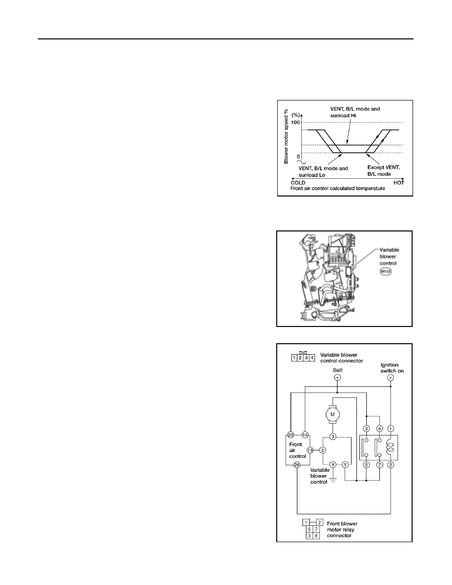
ATC-80
TROUBLE DIAGNOSIS
Revision: May 2004
2004 Quest
Blower Speed Compensation
Sunload
When the in-vehicle temperature and the set temperature are very close, the blower will be operating at low
speed. The speed will vary depending on the sunload. During conditions of low or no sunload, the blower
operates at low speed. During high sunload conditions, the front air control causes the blower speed to
increase.
Fan Speed Control Specification
COMPONENT DESCRIPTION
Variable Blower Control
The variable blower control is located on the cooling unit. The vari-
able blower control receives a gate voltage from the front air control
to steplessly maintain the blower fan motor voltage in the 0 to 5 volt
range (approx.).
DIAGNOSTIC PROCEDURE FOR BLOWER MOTOR
SYMPTOM: Blower motor operation is malfunctioning under starting
fan speed control.
WJIA0441E
WJIA0442E
WJIA0443E
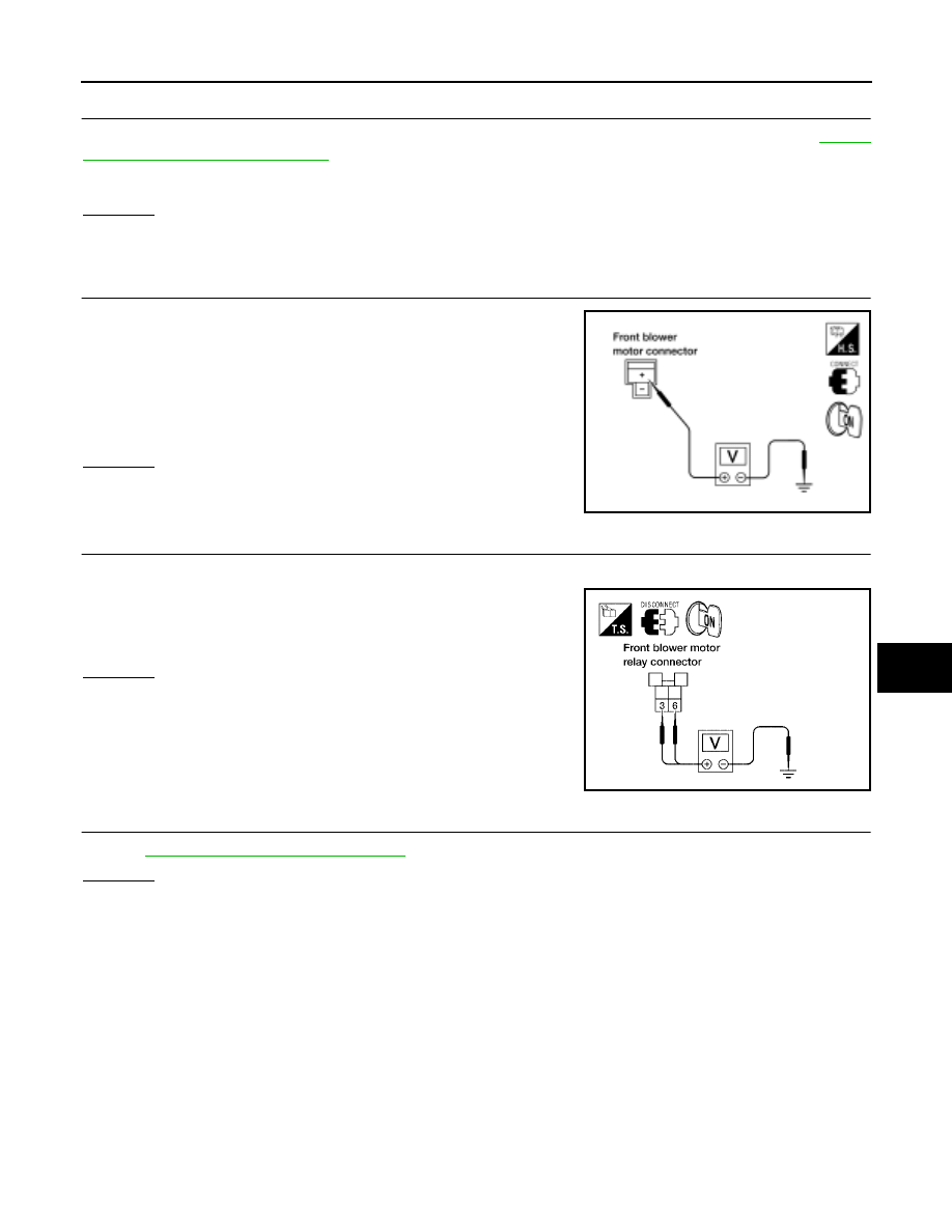
TROUBLE DIAGNOSIS
ATC-81
C
D
E
F
G
H
I
K
L
M
A
B
ATC
Revision: May 2004
2004 Quest
1.
CHECK FUSES
Check 20A fuses [No. 28 and 30 (Located in the fuse and fusible link box)]. For fuse layout. Refer to
OK or NG
OK
>> GO TO 2.
NG
>> GO TO 10.
2.
CHECK FRONT BLOWER MOTOR POWER SUPPLY CIRCUIT
1.
Disconnect front blower motor connector.
2.
Press the mode switch to select any mode except off.
3.
Set fan switch to high.
4.
Check voltage between front blower motor harness connector
M62 terminal + (W/L) and ground.
OK or NG
OK
>> GO TO 12.
NG
>> GO TO 3.
3.
CHECK FRONT BLOWER MOTOR RELAY (SWITCH SIDE) POWER SUPPLY CIRCUIT
1.
Disconnect front blower motor relay connector.
2.
Check voltage between front blower motor relay harness con-
nector H2 terminals 3 (L) and 6 (L/W) and ground.
OK or NG
OK
>> GO TO 4.
NG
>> Repair harness or connector.
4.
CHECK FRONT BLOWER MOTOR RELAY
Refer to
ATC-84, "Front Blower Motor Relay"
OK or NG
OK
>> GO TO 5.
NG
>> Replace front blower motor relay.
Fuses are good.
Battery voltage should exist.
WJIA0326E
Battery voltage should exist.
LJIA0077E
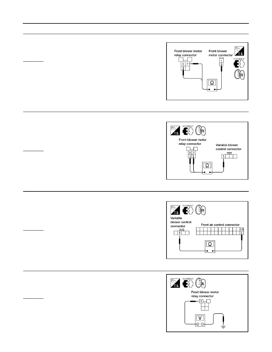
ATC-82
TROUBLE DIAGNOSIS
Revision: May 2004
2004 Quest
5.
CHECK FRONT BLOWER MOTOR RELAY (SWITCH SIDE) CIRCUIT FOR OPEN
Check continuity between front blower motor relay harness connector H2 terminals 5 (W/L) and 7 (W/L)
and front blower motor harness connector M62 terminal + (W/L).
OK or NG
OK
>> GO TO 6.
NG
>> Repair harness or connector.
6.
CHECK VARIABLE BLOWER CONTROL POWER SUPPLY CIRCUIT FOR OPEN
1.
Disconnect variable blower control harness connector.
2.
Check continuity between front blower motor relay harness con-
nector H2 terminals 5 (W/L) and 7 (W/L) and variable blower
control harness connector M122 terminal 1 (W/L).
OK or NG
OK
>> GO TO 7.
NG
>> Repair harness or connector.
7.
CHECK VARIABLE BLOWER CONTROL SIGNAL CIRCUIT
1.
Disconnect front air control connector.
2.
Check continuity between front air control connector M49 termi-
nal 13 (O) and variable blower control connector M122 terminal
2 (O).
OK or NG
OK
>> GO TO 8.
NG
>> Repair harness or connector.
8.
CHECK FRONT BLOWER MOTOR RELAY (COIL SIDE) POWER SUPPLY
Check voltage between front blower motor relay connector H2 termi-
nal 1 (G/Y) and ground.
OK or NG
OK
>> GO TO 9.
NG
>> Repair harness or connector.
Continuity should exist.
WJIA0968E
Continuity should exist.
LJIA0078E
Continuity should exist.
LJIA0079E
Battery voltage should exist.
LJIA0080E
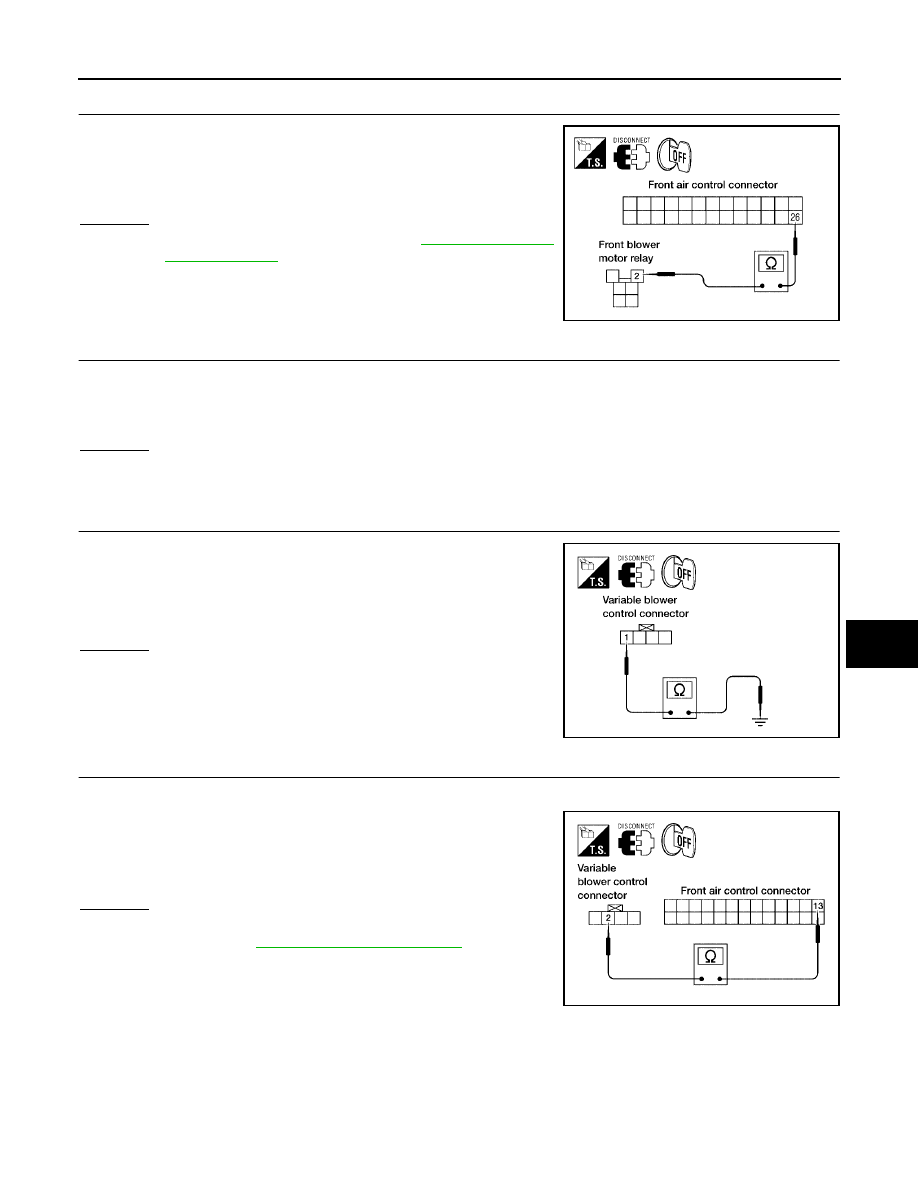
TROUBLE DIAGNOSIS
ATC-83
C
D
E
F
G
H
I
K
L
M
A
B
ATC
Revision: May 2004
2004 Quest
9.
CHECK FRONT BLOWER MOTOR RELAY (COIL SIDE) GROUND CIRCUIT
Check continuity between front blower motor relay connector H2 ter-
minal 2 (G/B) and front air control harness connector M49 terminal
26 (G/B).
OK or NG
OK
>> Replace front air control. Refer to
.
NG
>> Repair harness or connector.
10.
REPLACE FUSES
1.
Replace fuses.
2.
Activate the front blower motor.
3.
Does fuse blow?
Yes or No
Yes
>> GO TO 11.
No
>> Inspection End.
11.
CHECK FRONT BLOWER MOTOR POWER SUPPLY CIRCUIT FOR SHORT
1.
Disconnect front blower motor harness connector.
2.
Check continuity between variable blower control harness con-
nector M122 terminal 1 (W/L) and ground.
OK or NG
OK
>> GO TO 12.
NG
>> Repair harness or connector.
12.
CHECK VARIBLE BLOWER CONTROL SIGNAL CIRCUIT
1.
Disconnect front air control connector
2.
Check continuity between front air control connector M49 termi-
nal 13 (O) and variable blower control connector M122 terminal
2 (O)
OK or NG
OK
>> Check blower motor, if OK replace variable blower con-
trol. Refer to
.
NG
>> Repair harness or connector.
Continuity should exist.
WJIA0471E
Continuity should not exist.
LJIA0075E
Continuity should exist.
LJIA0079E
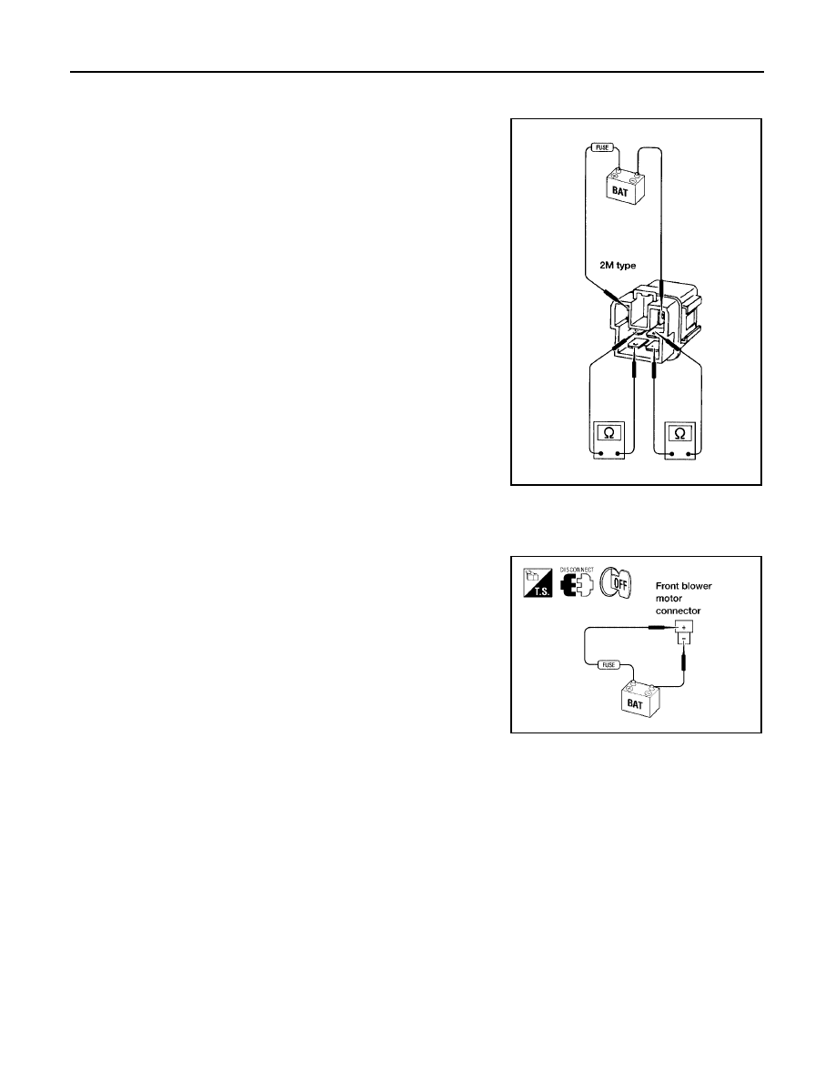
ATC-84
TROUBLE DIAGNOSIS
Revision: May 2004
2004 Quest
COMPONENT INSPECTION
Front Blower Motor Relay
Check continuity between terminals by supplying 12 volts and
ground to coil side terminals of relay.
Front Blower Motor
Confirm smooth rotation of the blower motor.
●
Ensure that there are no foreign particles inside the blower unit.
●
Apply 12 volts to terminal + and ground to terminal - and verify
that the motor operates freely and quietly.
LJIA0068E
LJIA0081E
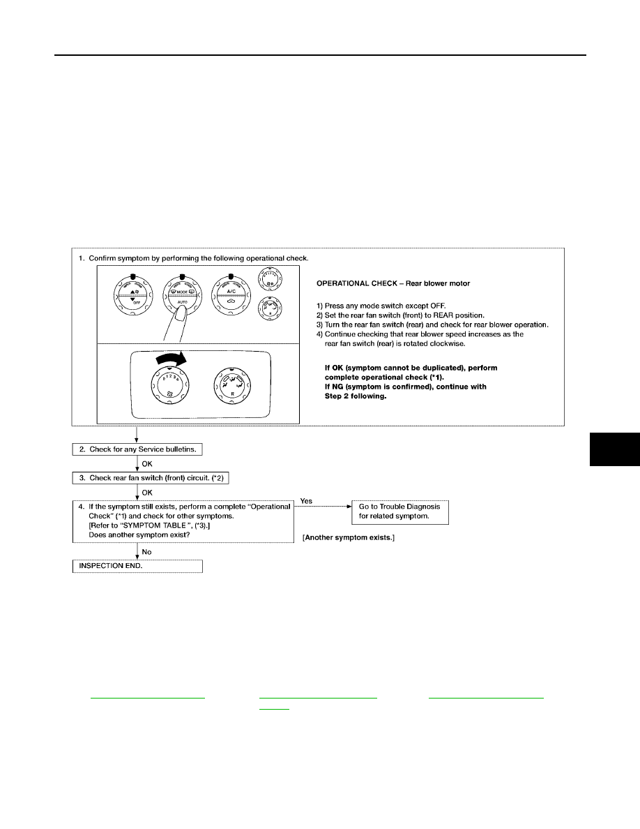
TROUBLE DIAGNOSIS
ATC-85
C
D
E
F
G
H
I
K
L
M
A
B
ATC
Revision: May 2004
2004 Quest
Rear Blower Motor Circuit
EJS001R3
SYMPTOM:
●
Blower motor operation is malfunctioning.
INSPECTION FLOW
*1
*2
ATC-94, "Rear Blower Switch
(Front)"
*3
LJIA0095E
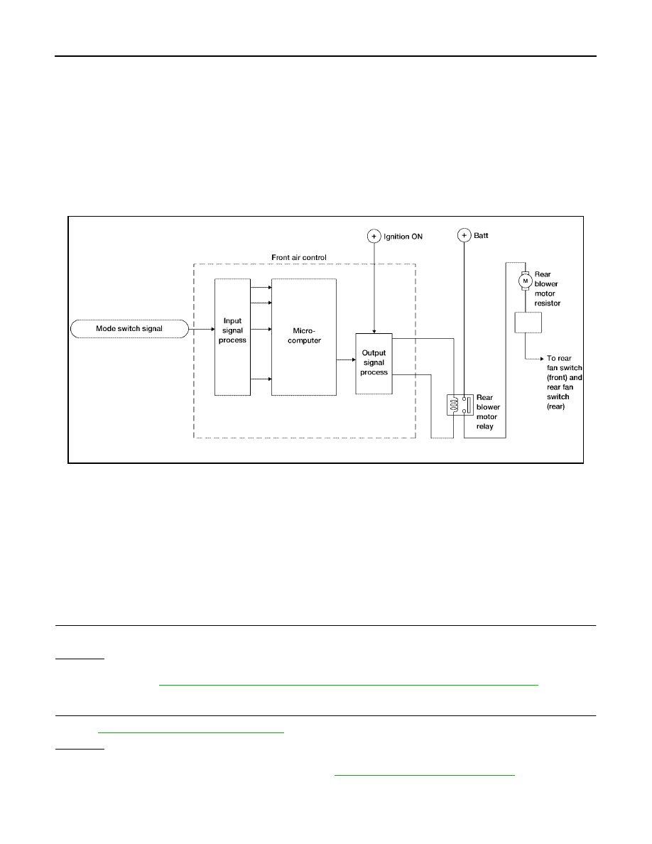
ATC-86
TROUBLE DIAGNOSIS
Revision: May 2004
2004 Quest
SYSTEM DESCRIPTION
Component Parts
Rear fan speed control system components are:
●
Front air control
●
Rear blower switch (front)
●
Rear blower switch (rear)
●
Rear blower motor resistor
●
Rear blower motor
●
Rear blower motor relay
System Operation
Rear Fan Control
When the rear blower switch (front) is in the OFF position, the rear blower motor cannot operate.
When the rear blower switch (front) is in the REAR position, it allows the rear blower switch (rear) to control
the rear blower motor speed. In any other position (1-4), the rear blower switch (front) controls the rear blower
motor speed regardless of the rear blower switch (rear) position.
DIAGNOSTIC PROCEDURE FOR REAR BLOWER MOTOR
Rear Blower Switch (Rear) Circuit
SYMPTOM:
●
Rear blower motor does not rotate when rear blower switch (front) is set to REAR position.
1.
CHECK REAR BLOWER MOTOR OPERATION
Blower motor rotates normally when rear blower switch (front) is set at 1 - 4 speed.
OK or NG
OK
>> GO TO 2.
NG
>> Refer to
ATC-88, "Trouble Diagnosis Procedure For Rear Blower Motor (1 - 4 Speed)"
.
2.
CHECK REAR BLOWER SWITCH (FRONT)
ATC-94, "Rear Blower Switch (Front)"
OK or NG
OK
>> GO TO 3.
NG
>> Replace rear blower switch (front). Refer to
ATC-127, "Removal and Installation"
LJIA0096E
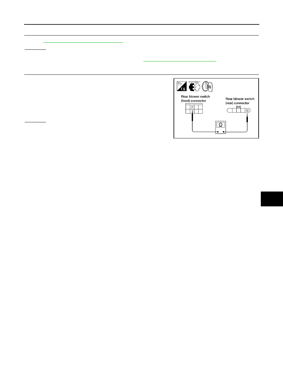
TROUBLE DIAGNOSIS
ATC-87
C
D
E
F
G
H
I
K
L
M
A
B
ATC
Revision: May 2004
2004 Quest
3.
CHECK REAR BLOWER SWITCH (REAR)
Refer to
ATC-94, "Rear Blower Switch (Rear)"
.
OK or NG
OK
>> GO TO 4.
NG
>> Replace rear blower switch (rear). Refer to
.
4.
CHECK CIRCUIT CONTINUITY
1.
Disconnect rear blower switch (front) harness connector and
rear blower switch (rear) harness connector.
2.
Check voltage between rear blower switch (front) harness con-
nector M52 terminal 2 (W) and rear blower switch (rear) harness
connector B141 terminal 10 (W).
OK or NG
OK
>> Inspection End.
NG
>> Repair harness or connector.
Continuity should exist.
LJIA0098E
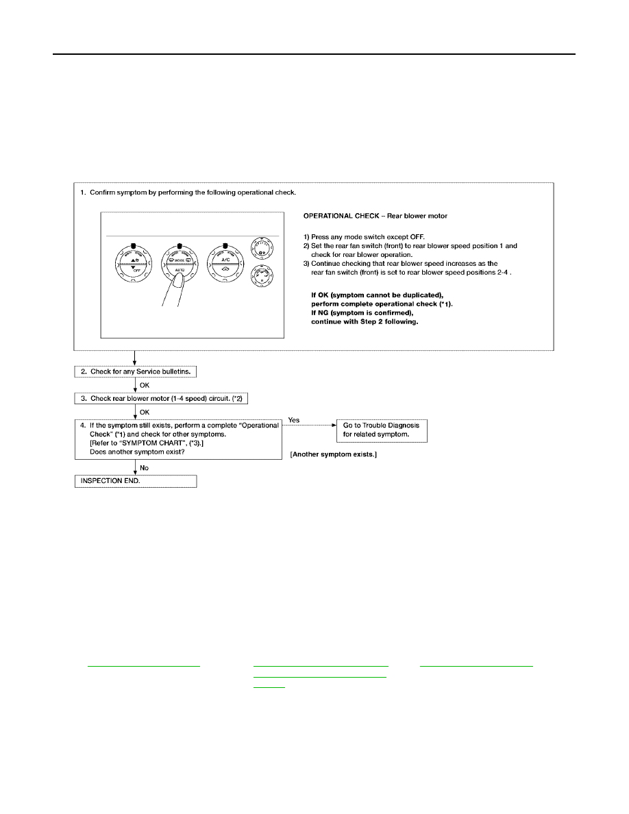
ATC-88
TROUBLE DIAGNOSIS
Revision: May 2004
2004 Quest
Trouble Diagnosis Procedure For Rear Blower Motor (1 - 4 Speed)
SYMPTOM:
●
Rear blower motor does not rotate when rear blower switch (front) is set at 1 - 4 speed.
Inspection Flow
*1
*2
ATC-88, "Trouble Diagnosis Proce-
dure For Rear Blower Motor (1 - 4
Speed)"
*3
LJIA0097E
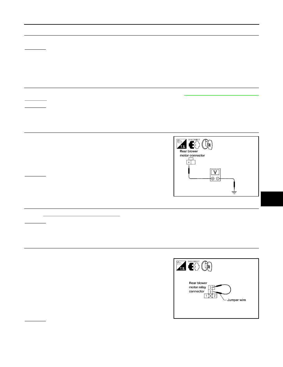
TROUBLE DIAGNOSIS
ATC-89
C
D
E
F
G
H
I
K
L
M
A
B
ATC
Revision: May 2004
2004 Quest
1.
DIAGNOSTIC PROCEDURE
Blower motor rotates normally at each speed.
OK or NG
OK
>> Inspection End.
NG
>> 1. Does not rotate at any speed, GO TO 2.
2. Does not rotate at 1 - 3 speed, GO TO 13.
3. Does not rotate at 4 speed, GO TO 18.
2.
CHECK FUSES
Check 15A fuses [Nos. 10 and 11, located in the fuse block (J/B)]. Refer to
.
OK or NG
OK
>> GO TO 3.
NG
>> GO TO 8.
3.
CHECK REAR BLOWER MOTOR POWER SUPPLY
1.
Disconnect rear blower motor harness connector.
2.
Select any rear blower speed except OFF.
3.
Check voltage between rear blower motor harness connector
B134 terminal + (L/R) and ground.
OK or NG
OK
>> GO TO 11.
NG
>> GO TO 4.
4.
CHECK REAR BLOWER MOTOR RELAY
Refer to
ATC-94, "Rear Blower Motor Relay"
OK or NG
OK
>> GO TO 5.
NG
>> Replace rear blower motor relay.
5.
CHECK REAR BLOWER MOTOR POWER FROM RELAY TO REAR BLOWER MOTOR
1.
Reconnect rear blower motor harness connector.
2.
Disconnect rear blower motor relay.
3.
Turn ignition switch ON and select any rear blower speed except
OFF.
4.
Set rear blower switch (front) to any position except OFF, REAR,
or 4 - speed.
5.
Momentarily (no more than 4 seconds), connect a jumper wire
between rear blower motor relay connector J1 (harness side)
terminals 3 and 5.
OK or NG
OK
>> GO TO 6.
NG
>> GO TO 10.
Battery voltage should exist.
LJIA0099E
Rear blower motor should rotate.
WJIA0972E
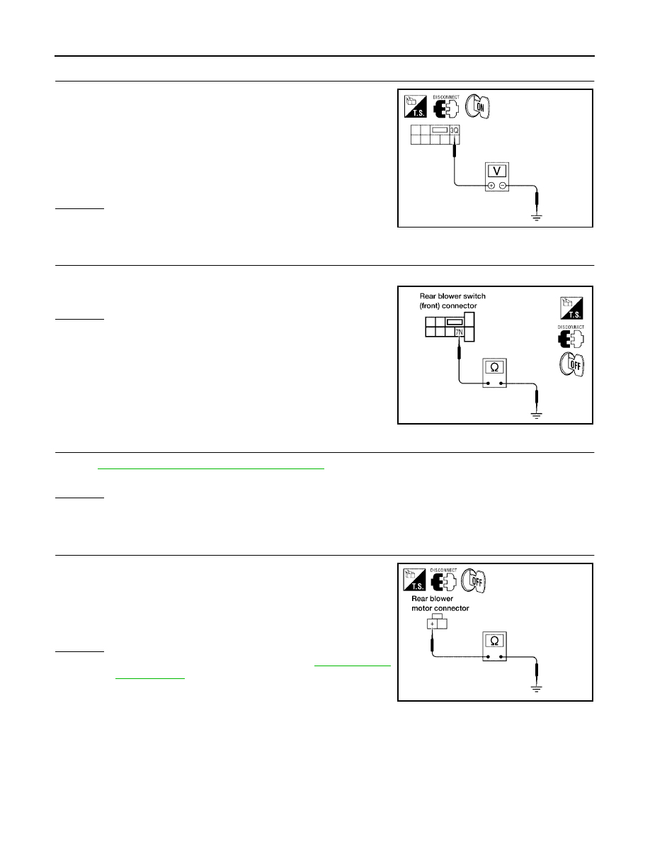
ATC-90
TROUBLE DIAGNOSIS
Revision: May 2004
2004 Quest
6.
CHECK REAR BLOWER MOTOR RELAY (COIL SIDE) POWER SUPPLY CIRCUIT
1.
Disconnect fuse block (J/B) harness connector.
2.
Turn ignition switch ON.
3.
Set rear blower switch (front) to any position except OFF, REAR,
or 4 - speed.
4.
Check voltage between fuse block (J/B) harness connector E30
terminal 3Q (W/G) and ground.
OK or NG
OK
>> GO TO 7.
NG
>> GO TO 20.
7.
CHECK REAR BLOWER MOTOR RELAY (COIL SIDE) GROUND CIRCUIT
Check continuity between fuse block (J/B) harness connector M3 terminal 7N (B) and ground.
OK or NG
OK
>> Replace fuse block (J/B).
NG
>> Repair harness or connector.
8.
REPLACE FUSE
PG-71, "FUSE BLOCK-JUNCTION BOX(J/B)"
Fuse should not open when rear blower motor is activated.
OK or NG
OK
>> Inspection End.
NG
>> GO TO 9.
9.
CHECK REAR BLOWER MOTOR POWER SUPPLY CIRCUIT FOR SHORT
1.
Disconnect battery cables and rear blower motor harness con-
nector.
2.
Check continuity between rear blower motor harness connector
B134 terminal + (L/R) and ground.
OK or NG
OK
>> Check rear blower motor. Refer to
.
NG
>> Repair harness or connector.
Battery voltage should exist.
LJIA0101E
Continuity should exist.
LJIA0102E
Continuity should not exist.
LJIA0104E
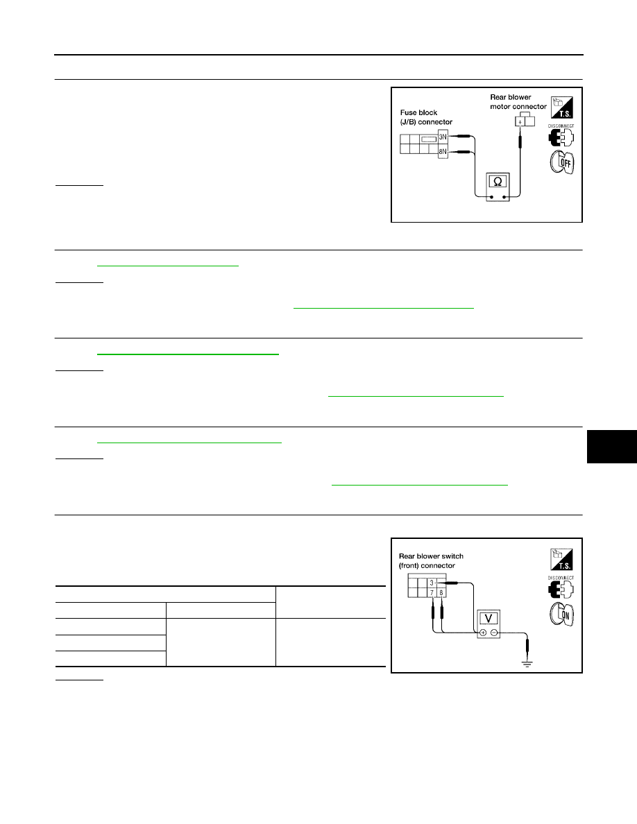
TROUBLE DIAGNOSIS
ATC-91
C
D
E
F
G
H
I
K
L
M
A
B
ATC
Revision: May 2004
2004 Quest
10.
CHECK REAR BLOWER MOTOR RELAY (SWITCH SIDE) POWER SUPPLY CIRCUIT
1.
Disconnect fuse block (J/B) and rear blower motor harness con-
nectors.
2.
Check continuity between fuse block (J/B) harness connector
M3 terminal 3N (L/R) and 8N (L/R) and rear blower motor har-
ness connector B134 terminal + (L/R).
OK or NG
OK
>> GO TO 20.
NG
>> Repair harness or connector.
11.
CHECK REAR BLOWER MOTOR
Refer to
OK or NG
OK
>> GO TO 12.
NG
>> Replace rear blower motor. Refer to
12.
CHECK REAR BLOWER SWITCH (FRONT)
Refer to
ATC-94, "Rear Blower Switch (Front)"
OK or NG
OK
>> GO TO 15.
NG
>> Replace rear blower switch (front). Refer to
ATC-127, "Removal and Installation"
.
13.
CHECK REAR BLOWER MOTOR RESISTOR
Refer to
ATC-95, "Rear Blower Motor Resistor"
OK or NG
OK
>> GO TO 14.
NG
>> Replace rear blower motor resistor. Refer to
ATC-152, "Removal and Installation"
14.
CHECK REAR BLOWER SWITCH (FRONT) CIRCUIT
1.
Disconnect rear blower switch (front).
2.
Reconnect rear blower motor resistor harness connector.
3.
Check voltage between each rear blower switch (front) connec-
tor M52 terminals 3 (LG), 7 (LG/B), and 8 (G), and ground.
OK or NG
OK
>> GO TO 17.
NG
>> GO TO 16.
Continuity should exist.
LJIA0107E
Terminal No.
Voltage
(Approx.)
+
-
3
Ground
12V
7
8
LJIA0108E
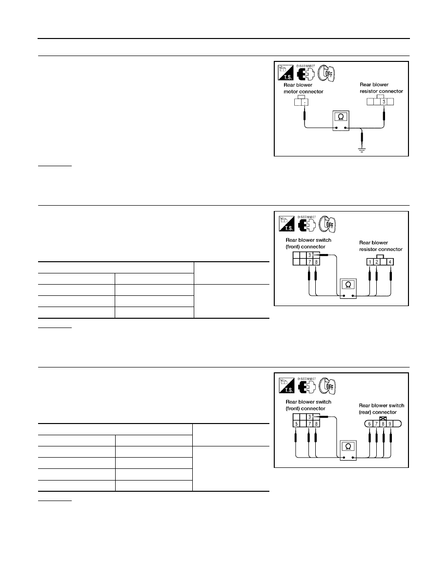
ATC-92
TROUBLE DIAGNOSIS
Revision: May 2004
2004 Quest
15.
CHECK REAR BLOWER MOTOR GROUND CIRCUIT TO REAR BLOWER MOTOR RESISTOR
1.
Disconnect rear blower motor and rear blower motor resistor
harness connector.
2.
Check continuity between rear blower motor connector B134
terminal - (L/B) and rear blower motor resistor harness connec-
tor B133 terminal 3 (L/B).
3.
Check continuity between rear blower motor connector B134
terminal - (L/B) and ground.
OK or NG
OK
>> GO TO 16.
NG
>> Repair harness or connector.
16.
CHECK REAR BLOWER SWITCH (FRONT) CIRCUIT
1.
Disconnect rear blower resistor harness connector.
2.
Check continuity between rear blower switch (front) connector
M52 terminals 3 (LG), 7 (LG/B), and 8 (G), and rear blower
motor resistor connector B133 terminals 1 (LG), 4 (LG/B), and 2
(G).
OK or NG
OK
>> Inspection End.
NG
>> Repair harness or connector.
17.
CHECK REAR BLOWER SWITCH (FRONT) CIRCUIT
1.
Disconnect rear blower switch (rear) harness connectors.
2.
Check continuity between rear blower switch (front) connector
M52 terminals 3 (LG), 5 (L/B), 7 (LG/B), and 8 (G), and rear
blower switch (rear) connector B141 terminals 9 (LG), 6 (L/B), 8
(LG/B), and 7 (G).
OK or NG
OK
>> GO TO 18.
NG
>> Repair harness or connector.
Continuity should exist.
Continuity should not exist.
LJIA0118E
Terminal No.
Continuity
Rear blower switch (front)
Rear blower motor resistor
3
1
Should exist
7
4
8
2
LJIA0109E
Terminal No.
Continuity
Rear blower switch (front)
Rear blower switch (rear)
3
9
Should exist
5
6
7
8
8
7
LJIA0110E
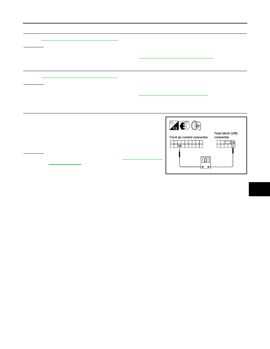
TROUBLE DIAGNOSIS
ATC-93
C
D
E
F
G
H
I
K
L
M
A
B
ATC
Revision: May 2004
2004 Quest
18.
CHECK REAR BLOWER SWITCH (FRONT)
Refer to
ATC-94, "Rear Blower Switch (Front)"
OK or NG
OK
>> GO TO 19.
NG
>> Replace rear blower switch (front). Refer to
ATC-127, "Removal and Installation"
.
19.
CHECK REAR BLOWER SWITCH (REAR)
Refer to
ATC-94, "Rear Blower Switch (Rear)"
.
OK or NG
OK
>> Inspection End.
NG
>> Replace rear blower switch (rear). Refer to
20.
CHECK CIRCUIT BETWEEN FRONT AIR CONTROL AND FUSE BLOCK (J/B) [REAR BLOWER
MOTOR RELAY (COIL SIDE) POWER]
1.
Disconnect front air control and fuse block (J/B) connectors.
2.
Check continuity between front air control harness connector
M50 terminal 38 (W/G) and fuse block (J/B) connector E30 ter-
minal 3Q (W/G).
OK or NG
OK
>> Replace front air control. Refer to
.
NG
>> Repair harness or connector.
Continuity should exist.
LJIA0111E
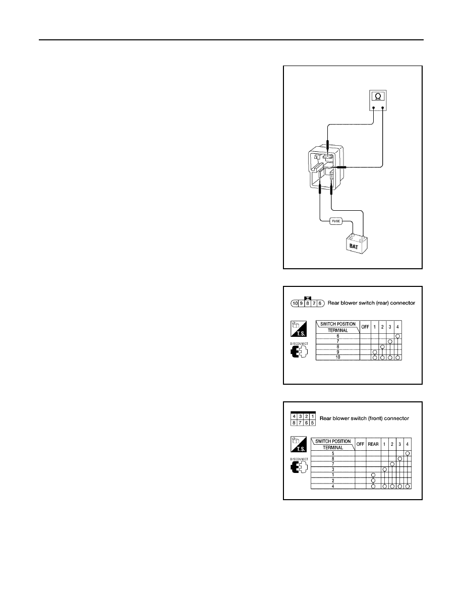
ATC-94
TROUBLE DIAGNOSIS
Revision: May 2004
2004 Quest
COMPONENT INSPECTION
Rear Blower Motor Relay
Check circuit continuity between terminals by supplying 12 volts and
ground to coil side terminals of relays.
Rear Blower Switch (Rear)
Check continuity between terminals at each switch position.
Rear Blower Switch (Front)
Check continuity between terminals at each switch position.
WJIA0973E
LJIA0113E
LJIA0114E
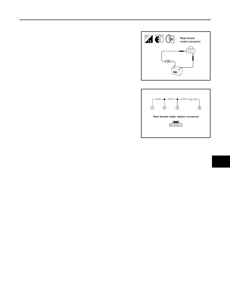
TROUBLE DIAGNOSIS
ATC-95
C
D
E
F
G
H
I
K
L
M
A
B
ATC
Revision: May 2004
2004 Quest
Rear Blower Motor
Check that there are no foreign particles inside the intake unit.
Apply 12 volts to terminal + and ground to terminal - and ensure that
the blower motor rotates freely and quietly.
Rear Blower Motor Resistor
Check continuity between terminals. There will be resistance, but
there should not be an open or short between any two terminals.
LJIA0115E
LJIA0116E
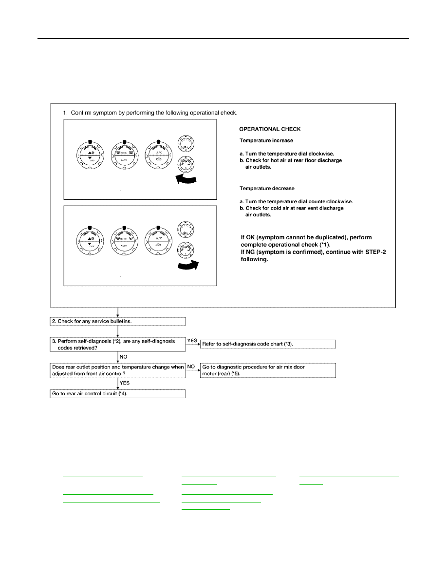
ATC-96
TROUBLE DIAGNOSIS
Revision: May 2004
2004 Quest
Rear Air Control Circuit
EJS001R4
SYMPTOM:
●
Temperature cannot be adjusted from the rear air control.
INSPECTION FLOW
*1
*2
ATC-50, "A/C System Self-diagno-
sis Function"
*3
ATC-51, "SELF-DIAGNOSIS CODE
CHART"
*4
ATC-97, "DIAGNOSTIC PROCE-
DURE FOR REAR AIR CONTROL"
*5
ATC-68, "DIAGNOSTIC PROCE-
DURE FOR AIR MIX DOOR
MOTOR (REAR)"
LJIA0119E
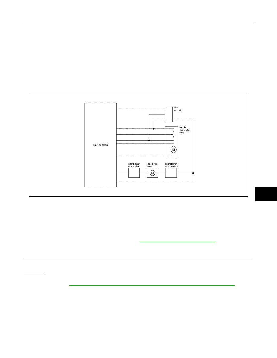
TROUBLE DIAGNOSIS
ATC-97
C
D
E
F
G
H
I
K
L
M
A
B
ATC
Revision: May 2004
2004 Quest
SYSTEM DESCRIPTION
Component Parts
Rear air control system components are:
●
Front air control
●
Rear air control
●
Air mix door motor (rear)
●
Rear blower motor relay
●
Rear blower motor resistor
●
Rear blower motor
System Operation
Rear Air Control
When the rear blower switch (front) (integral to the front air control) is in the REAR position the rear blower
motor speeds and the rear temperature/mode are controlled by the rear blower switch (rear) and the rear tem-
perature switch (rear) (both integral to the rear air control).
DIAGNOSTIC PROCEDURE FOR REAR AIR CONTROL
SYMPTOM:
●
Blower motor operation is malfunctioning. Refer to
ATC-85, "Rear Blower Motor Circuit"
●
Temperature/mode operation is malfunctioning.
1.
CHECK OPERATION FROM FRONT AIR CONTROL
Does rear temperature/mode operate normally from front air control?
Yes or No
Yes
>> GO TO 2.
No
>> Refer to
ATC-68, "DIAGNOSTIC PROCEDURE FOR AIR MIX DOOR MOTOR (REAR)"
LJIA0120E
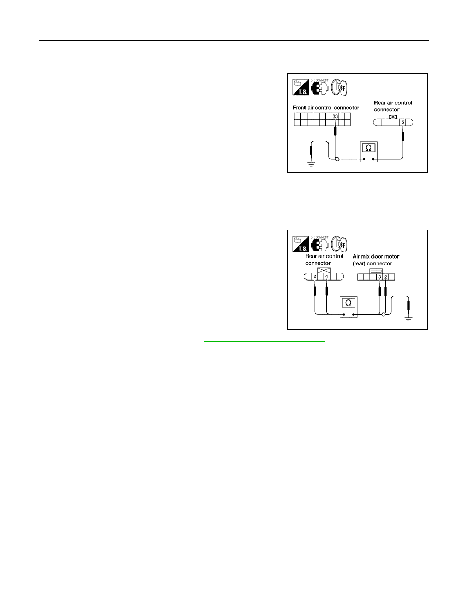
ATC-98
TROUBLE DIAGNOSIS
Revision: May 2004
2004 Quest
2.
CHECK CIRCUIT BETWEEN REAR AIR CONTROL AND FRONT AIR CONTROL FOR OPEN AND
SHORT
1.
Disconnect front air control and rear air control connectors.
2.
Check continuity between front air control harness connector
M50 terminal 33 (V) and rear air control harness connector B142
terminal 5 (V).
3.
Check continuity between rear air control harness connector
B142 terminal 5 (V) and ground.
OK or NG
OK
>> GO TO 3.
NG
>> Repair harness or connector.
3.
CHECK CIRCUIT BETWEEN REAR AIR CONTROL AND AIR MIX DOOR MOTOR (REAR) FOR OPEN
OR SHORT
1.
Disconnect air mix door motor (rear) connector.
2.
Check continuity between rear air control harness connector
B142 terminal 2 (Y) and 4 (W/G and air mix door motor (rear)
harness connector B146 terminal 2 (Y) and 3 (W/G).
3.
Check continuity between rear air control harness connector
B142 terminals 2 (W/G) and 4 (Y) and ground.
OK or NG
OK
>> Replace rear air control. Refer to
.
NG
>> Repair harness or connector.
Continuity should exist.
Continuity should not exist.
LJIA0121E
Continuity should exist.
Continuity should not exist.
LJIA0122E
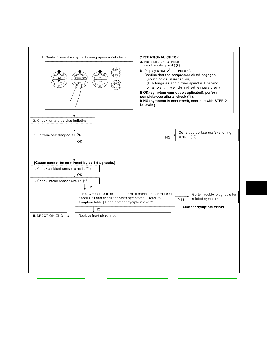
TROUBLE DIAGNOSIS
ATC-99
C
D
E
F
G
H
I
K
L
M
A
B
ATC
Revision: May 2004
2004 Quest
Magnet Clutch Circuit
EJS001NR
SYMPTOM: Magnet clutch does not engage.
INSPECTION FLOW
*1
*2
ATC-50, "A/C System Self-diagnosis
Function"
*3
ATC-51, "SELF-DIAGNOSIS CODE
CHART"
*4
ATC-117, "Ambient Sensor Circuit"
.
*5
ATC-125, "Intake Sensor Circuit"
WJIA1024E
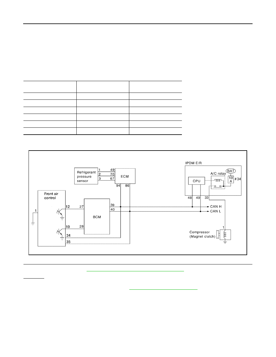
ATC-100
TROUBLE DIAGNOSIS
Revision: May 2004
2004 Quest
SYSTEM DESCRIPTION
The front air control controls compressor operation based on ambient and intake temperature and a signal
from ECM.
Low Temperature Protection Control
The front air control will turn the compressor ON or OFF as determined by a signal detected by the intake sen-
sor and the ambient sensor.
When intake air temperature is higher than the preset value, the compressor turns ON. The compressor turns
OFF when intake air temperature is lower than the preset value. That preset value is dependent on the ambi-
ent temperature, refer to the following table.
DIAGNOSTIC PROCEDURE FOR MAGNET CLUTCH
SYMPTOM: Magnet clutch does not engage when A/C switch is ON.
1.
CHECK INTAKE SENSOR CIRCUIT
Check intake sensor. Refer to
ATC-50, "A/C System Self-diagnosis Function"
OK or NG
OK
>> GO TO 2.
NG
>> Malfunctioning intake sensor. Refer to
ATC-125, "Intake Sensor Circuit"
.
Ambient temperature
°
C (
°
F)
Compressor ON
intake temperature C (
°
F)
Compressor OFF
intake temperature C (
°
F)
0 (32)
2.5 (37)
2.0 (36)
10 (50)
2.5 (37)
2.0 (36)
20 (68)
2.5 (37)
1.5 (35)
30 (86)
2.0 (36)
0.5 (33)
40 (104)
2.0 (36)
0.5 (33)
50 (122)
2.0 (36)
0.5 (33)
WJIA0472E
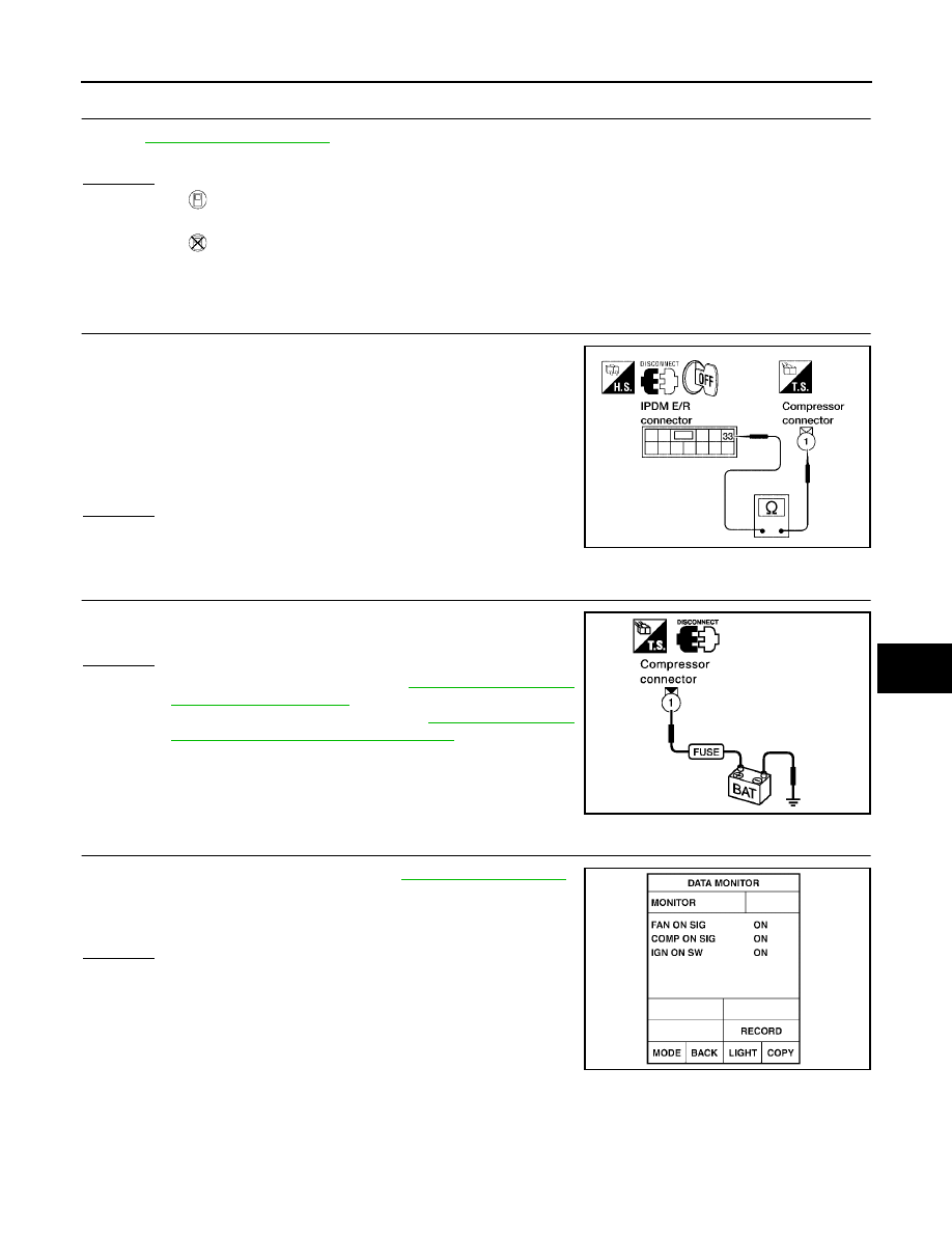
TROUBLE DIAGNOSIS
ATC-101
C
D
E
F
G
H
I
K
L
M
A
B
ATC
Revision: May 2004
2004 Quest
2.
PERFORM AUTO ACTIVE TEST
Refer to
.
Does magnet clutch operate?
Yes or No
Yes
>>
●
WITH CONSULT-II
GO TO 5.
●
WITHOUT CONSULT-II
GO TO 6.
No
>> Check 10A fuse (No. 33, located in IPDM E/R), and GO TO 3.
3.
CHECK CIRCUIT CONTINUITY BETWEEN IPDM E/R AND COMPRESSOR
1.
Turn ignition switch OFF.
2.
Disconnect IPDM E/R connector and compressor (magnet
clutch) connector.
3.
Check continuity between IPDM E/R harness connector E124
terminal 33 (Y/B) and compressor harness connector F3 termi-
nal 1 (Y/B).
OK or NG
OK
>> GO TO 4.
NG
>> Repair harness or connector.
4.
CHECK MAGNET CLUTCH CIRCUIT
Check for operation sound when applying battery voltage direct cur-
rent to terminal.
OK or NG
OK
>> Replace IPDM E/R. Refer to
NG
>> Replace magnet clutch. Refer to
and Installation for Compressor Clutch"
5.
CHECK BCM INPUT (COMPRESSOR ON) SIGNAL
Check compressor ON/OFF signal. Refer to
.
OK or NG
OK
>> GO TO 8.
NG
>> GO TO 6.
33 – 1
: Continuity should exist.
WJIA0331E
SJIA0197E
A/C SW ON
: COMP ON SIG ON
A/C SW OFF
: COMP ON SIG OFF
WJIA0469E
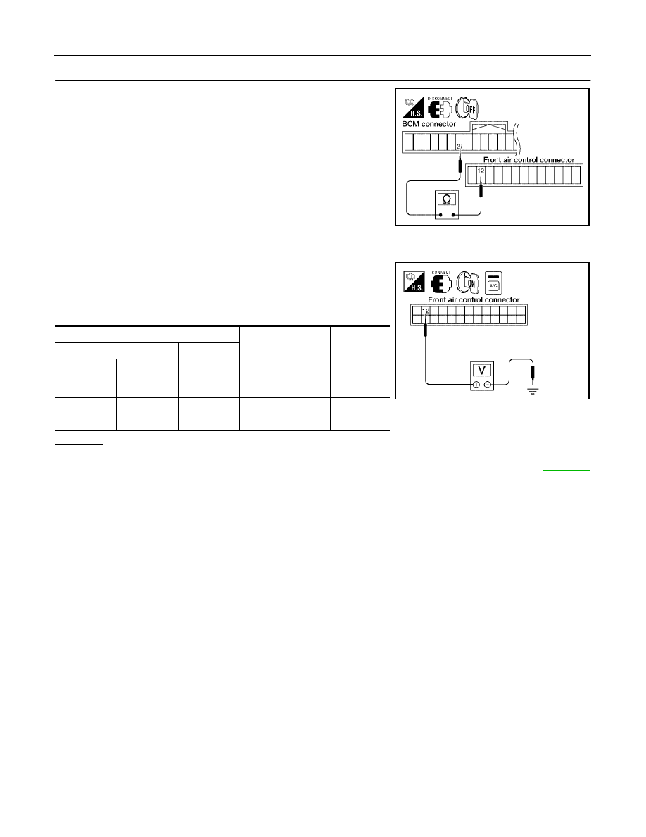
ATC-102
TROUBLE DIAGNOSIS
Revision: May 2004
2004 Quest
6.
CHECK CIRCUIT CONTINUITY BETWEEN BCM AND FRONT AIR CONTROL
1.
Turn ignition switch OFF.
2.
Disconnect BCM connector and front air control connector.
3.
Check continuity between BCM harness connector M18 terminal
27 (L/R) and front air control harness connector M49 terminal 12
(L/R).
OK or NG
OK
>> GO TO 7.
NG
>> Repair harness or connector.
7.
CHECK VOLTAGE FOR FRONT AIR CONTROL (COMPRESSOR ON SIGNAL)
1.
Reconnect BCM connector and front air control connector.
2.
Turn ignition switch ON.
3.
Check voltage between front air control harness connector M49
terminal 12 (L/R) and ground.
OK or NG
OK
>> GO TO 8.
NG-1
>> If the voltage is approx. 5V when A/C switch is ON, replace front air control. Refer to
NG-2
>> If the voltage is approx. 0V when A/C switch is OFF, replace BCM. Refer to
Continuity should exist.
WJIA0974E
Terminals
Condition
Voltage
(Approx.)
(+)
(-)
Front air
control con-
nector
Terminal No.
(Wire color)
M49
12 (L/R)
Ground
A/C switch: ON
0V
A/C switch: OFF
5V
WJIA0449E
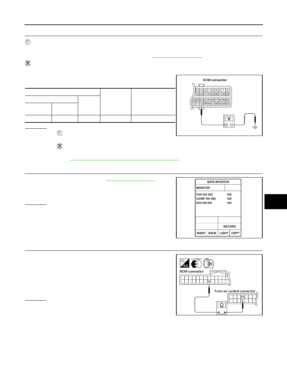
TROUBLE DIAGNOSIS
ATC-103
C
D
E
F
G
H
I
K
L
M
A
B
ATC
Revision: May 2004
2004 Quest
8.
CHECK REFRIGERANT PRESSURE SENSOR
WITH CONSULT-II
1.
Start engine.
2.
Check voltage of refrigerant pressure sensor. Refer to
WITHOUT CONSULT-II
1.
Start engine.
2.
Check voltage between ECM harness connector F54 terminal
70 (W) and ground.
OK or NG
OK
>>
●
WITH CONSULT-II
GO TO 9.
●
WITHOUT CONSULT-II
GO TO 10.
NG
EC-679, "REFRIGERANT PRESSURE SENSOR"
9.
CHECK BCM INPUT (FAN ON) SIGNAL
Check FAN ON/OFF signal. Refer to
OK or NG
OK
>> GO TO 12.
NG
>> GO TO 10.
10.
CHECK CIRCUIT CONTINUITY BETWEEN BCM AND FRONT AIR CONTROL
1.
Turn ignition switch OFF.
2.
Disconnect BCM connector and front air control connector.
3.
Check continuity between BCM harness connector M18 terminal
28 (L/Y) and front air control harness connector M49 terminal 10
(L/Y).
OK or NG
OK
>> GO TO 11.
NG
>> Repair harness or connector.
Terminals
Condition
Voltage
(Approx.)
(+)
(-)
ECM con-
nector
Terminal No.
(Wire color)
F54
70 (W)
Ground
A/C switch: ON
0.36 - 3.88V
LJIA0124E
FAN CONTROL SWITCH ON
: FAN ON SIG ON
FAN CONTROL SWITCH OFF
: FAN ON SIG OFF
WJIA0469E
Continuity should exist.
WJIA0450E
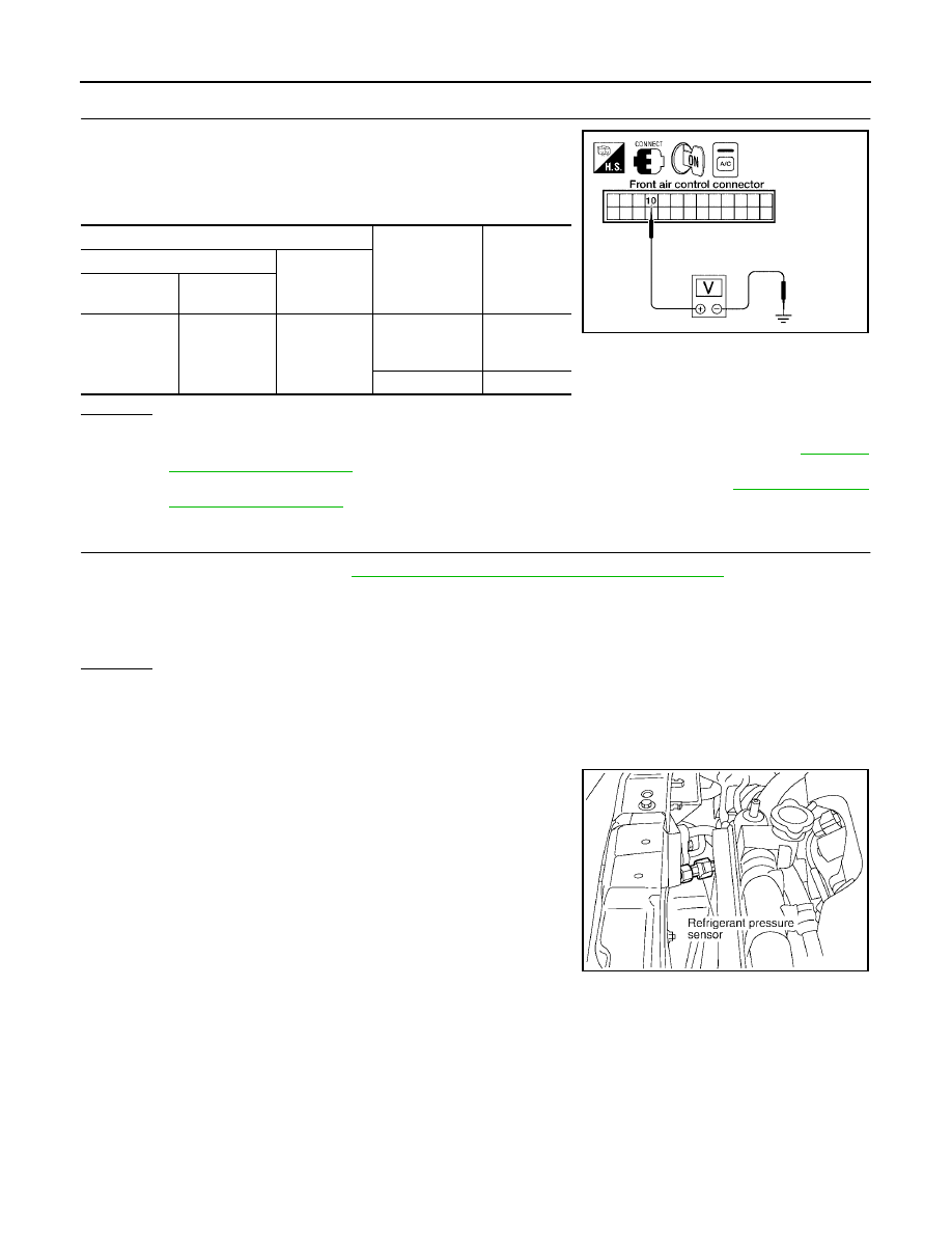
ATC-104
TROUBLE DIAGNOSIS
Revision: May 2004
2004 Quest
11.
CHECK VOLTAGE FOR FRONT AIR CONTROL (FAN ON SIGNAL)
1.
Reconnect BCM connector and front air control connector.
2.
Turn ignition switch ON.
3.
Check voltage between front air control harness connector M49
terminal 10 (L/Y) and ground.
OK or NG
OK
>> GO TO 12.
NG-1
>> If the voltage is approx. 5V when blower motor is ON, replace front air control. Refer to
NG-2
>> If the voltage is approx. 0V when blower motor is OFF, replace BCM. Refer to
12.
CHECK CAN COMMUNICATION
Check CAN communication. Refer to
ATC-30, "CAN Communication System Description"
.
●
BCM – ECM
●
ECM – IPDM E/R
●
ECM – Front air control
OK or NG
OK
>> Inspection End.
NG
>> Repair or replace malfunctioning part(s).
COMPONENT INSPECTION
Refrigerant Pressure Sensor
The refrigerant pressure sensor is attached to the condenser.
Terminals
Condition
Voltage
(Approx.)
(+)
(-)
Front air con-
trol connector
Terminal No.
(Wire color)
M49
10 (L/Y)
Ground
A/C switch: ON
Blower motor
operates
0V
A/C switch: OFF
5V
WJIA0451E
RJIA1795E
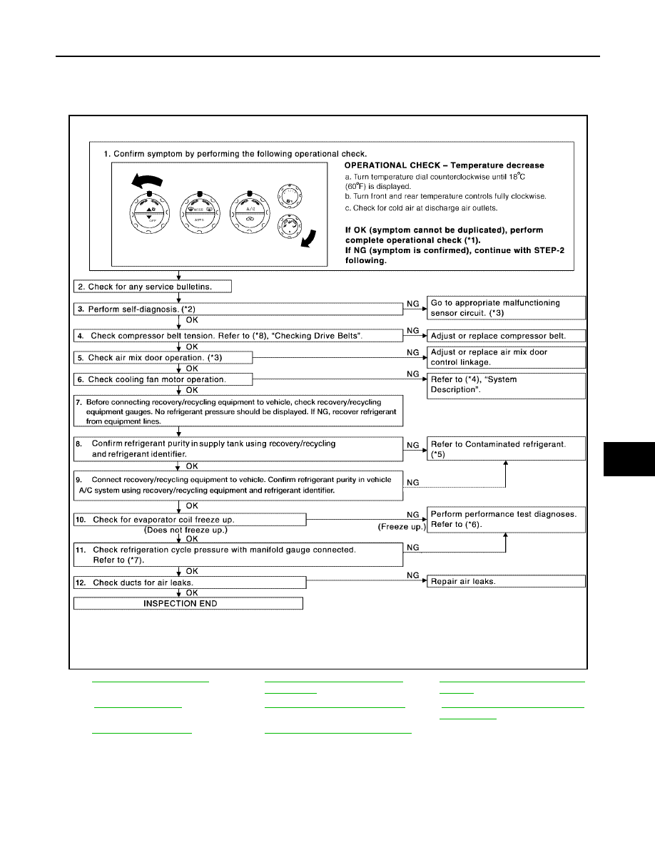
TROUBLE DIAGNOSIS
ATC-105
C
D
E
F
G
H
I
K
L
M
A
B
ATC
Revision: May 2004
2004 Quest
Insufficient Cooling
EJS001NS
SYMPTOM: Insufficient cooling
INSPECTION FLOW
*1
.
*2
ATC-50, "A/C System Self-diagno-
sis Function"
*3
ATC-51, "SELF-DIAGNOSIS CODE
CHART"
*4
.
*5
ATC-5, "Contaminated Refrigerant"
*6
.
*7
*8
WJIA1025E
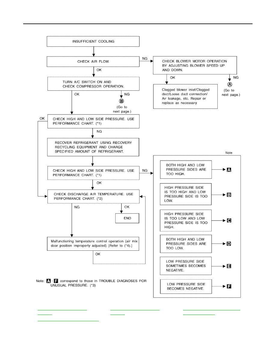
ATC-106
TROUBLE DIAGNOSIS
Revision: May 2004
2004 Quest
PERFORMANCE TEST DIAGNOSES
*1
*2
*3
ATC-109, "Trouble Diagnoses for
Unusual Pressure"
*4
ATC-62, "Air Mix Door Motor Circuit"
RJIA1601E
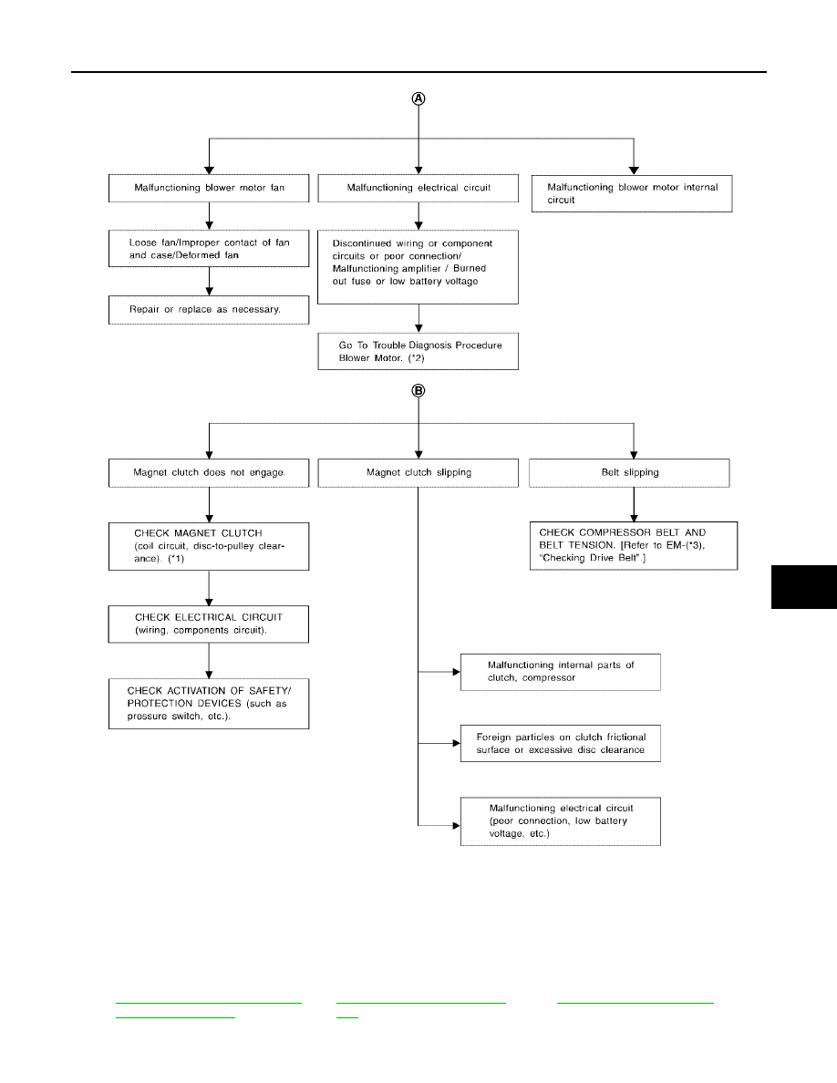
TROUBLE DIAGNOSIS
ATC-107
C
D
E
F
G
H
I
K
L
M
A
B
ATC
Revision: May 2004
2004 Quest
*1
ATC-163, "Removal and Installation
for Compressor Clutch"
.
*2
ATC-78, "Front Blower Motor Cir-
cuit"
.
*3
WJIA0361E
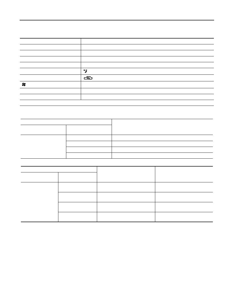
ATC-108
TROUBLE DIAGNOSIS
Revision: May 2004
2004 Quest
PERFORMANCE CHART
Test Condition
Testing must be performed as follows:
Test Reading
Recirculating-to-discharge Air Temperature Table
Ambient Air Temperature-to-operating Pressure Table
Vehicle location
Indoors or in the shade (in a well-ventilated place)
Doors
Closed
Windows
Open
Hood
Open
TEMP.
Max. COLD
Mode switch
(Ventilation) set
Recirculation (REC) switch
(Recirculation) set
Fan (blower) speed (FR and RR)
Max. speed set
Engine speed
Idle speed
RR system
ON
Operate the air conditioning system for 10 minutes before taking measurements.
Inside air (Recirculating air) at blower assembly inlet
Discharge air temperature at center ventilator
°
C (
°
F)
Relative humidity
%
Air temperature
°
C (
°
F)
50-70
25 (77)
9.7 - 13.7 (49 - 57)
30 (86)
12.6 - 16.6 (55 - 62)
35 (95)
14.9 - 19.9 (59 - 68)
40 (104)
17.3 - 23.3 (63 - 74)
Ambient air
High-pressure (Discharge side)
kPa (kg/cm
2
, psi)
Low-pressure (Suction side)
kPa (kg/cm
2
, psi)
Relative humidity
%
Air temperature
°
C (
°
F)
50-70
25 (77)
1,059 - 1,294
(10.8 - 13.2, 153.6 - 187.7)
216 - 255
(2.2 - 2.6, 31.3 - 37.0)
30 (86)
1,206 - 1,481
(12.3 - 15.1, 174.9 - 214.8)
255 - 304
(2.6 - 3.1, 37.0 - 44.1)
35 (95)
1,393 - 1,706
(14.2 - 17.4, 202.0 - 247.5)
275 - 343
(2.8 - 3.5, 39.8 - 49.8)
40 (104)
1,510 - 1,844
(15.4 - 18.8, 219.0 - 267.4)
343 - 422
(3.5 - 4.3, 49.8 - 61.2)
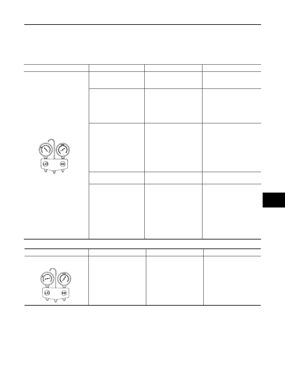
TROUBLE DIAGNOSIS
ATC-109
C
D
E
F
G
H
I
K
L
M
A
B
ATC
Revision: May 2004
2004 Quest
TROUBLE DIAGNOSES FOR UNUSUAL PRESSURE
Whenever system
′
s high and/or low side pressure is unusual, diagnose using a manifold gauge. The marker
above the gauge scale in the following tables indicates the standard (usual) pressure range. Since the stan-
dard (usual) pressure, however, differs from vehicle to vehicle, refer to above table (Ambient air temperature-
to-operating pressure table).
Both High- and Low-pressure Sides are Too High
High-pressure Side is Too High and Low-pressure Side is Too Low
Gauge indication
Refrigerant cycle
Probable cause
Corrective action
Both high- and low-pressure sides
are too high.
Pressure is reduced soon
after water is splashed on
condenser.
Excessive refrigerant charge
in refrigeration cycle
Reduce refrigerant until speci-
fied pressure is obtained.
Air suction by cooling fan is
insufficient.
Insufficient condenser cooling
performance
↓
1. Condenser fins are clogged.
2. Improper fan rotation of
cooling fan
●
Clean condenser.
●
Check and repair cooling fan
as necessary.
●
Low-pressure pipe is not
cold.
●
When compressor is
stopped high-pressure
value quickly drops by
approximately 196 kPa (2
kg/cm
2
, 28 psi). It then
decreases gradually there-
after.
Poor heat exchange in con-
denser
(After compressor operation
stops, high-pressure
decreases too slowly.)
↓
Air in refrigeration cycle
Evacuate repeatedly and
recharge system.
Engine tends to overheat.
Engine cooling systems mal-
function.
Check and repair engine cool-
ing system.
●
An area of the low-pres-
sure pipe is colder than
areas near the evaporator
outlet.
●
Plates are sometimes cov-
ered with frost.
●
Excessive liquid refrigerant
on low-pressure side
●
Excessive refrigerant dis-
charge flow
●
Expansion valve is open a
little compared with the
specification.
↓
Improper expansion valve
adjustment
Replace expansion valve.
AC359A
Gauge indication
Refrigerant cycle
Probable cause
Corrective action
High-pressure side is too high and
low-pressure side is too low.
Upper side of condenser and
high-pressure side are hot,
however, liquid tank is not so
hot.
High-pressure tube or parts
located between compressor
and condenser are clogged or
crushed.
●
Check and repair or replace
malfunctioning parts.
●
Check lubricant for contami-
nation.
AC360A
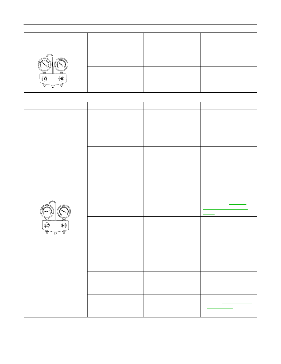
ATC-110
TROUBLE DIAGNOSIS
Revision: May 2004
2004 Quest
High-pressure Side is Too Low and Low-pressure Side is Too High
Both High- and Low-pressure Sides are Too Low
Gauge indication
Refrigerant cycle
Probable cause
Corrective action
High-pressure side is too low and
low-pressure side is too high.
High- and low-pressure sides
become equal soon after com-
pressor operation stops.
Compressor pressure opera-
tion is improper.
↓
Damaged inside compressor
packings.
Replace compressor.
No temperature difference
between high- and low-pres-
sure sides.
Compressor pressure opera-
tion is improper.
↓
Damaged inside compressor
packings.
Replace compressor.
AC356A
Gauge indication
Refrigerant cycle
Probable cause
Corrective action
Both high- and low-pressure sides
are too low.
●
There is a big temperature
difference between receiver
drier outlet and inlet. Outlet
temperature is extremely
low.
●
Liquid tank inlet and expan-
sion valve are frosted.
Liquid tank inside is slightly
clogged.
●
Replace liquid tank.
●
Check lubricant for contami-
nation.
●
Temperature of expansion
valve inlet is extremely low
as compared with areas
near liquid tank.
●
Expansion valve inlet may
be frosted.
●
Temperature difference
occurs somewhere in high-
pressure side.
High-pressure pipe located
between receiver drier and
expansion valve is clogged.
●
Check and repair malfunc-
tioning parts.
●
Check lubricant for contami-
nation.
Expansion valve and liquid
tank are warm or only cool
when touched.
Low refrigerant charge.
↓
Leaking fittings or compo-
nents.
Check refrigerant system for
leaks. Refer to
"Checking for Refrigerant
Leaks"
There is a big temperature dif-
ference between expansion
valve inlet and outlet while the
valve itself is frosted.
Expansion valve closes a little
compared with the specifica-
tion.
↓
1. Improper expansion valve
adjustment.
2. Malfunctioning expansion
valve.
3. Outlet and inlet may be
clogged.
●
Remove foreign particles by
using compressed air.
●
Check lubricant for contami-
nation.
An area of the low-pressure
pipe is colder than areas near
the evaporator outlet.
Low-pressure pipe is clogged
or crushed.
●
Check and repair malfunc-
tioning parts.
●
Check lubricant for contami-
nation.
Air flow volume is too low.
Evaporator is frozen.
●
Check intake sensor circuit.
Refer to
●
Replace compressor.
AC353A
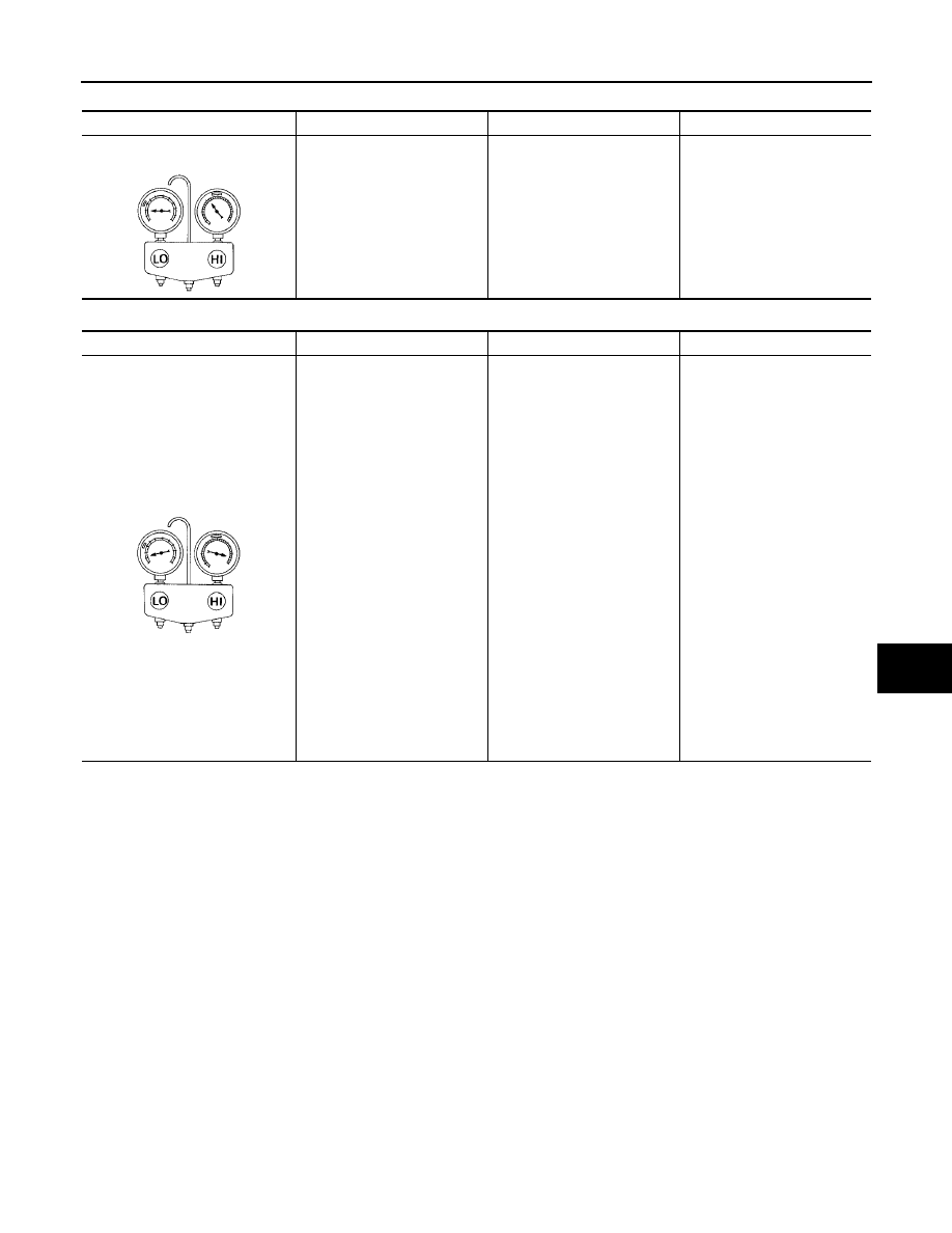
TROUBLE DIAGNOSIS
ATC-111
C
D
E
F
G
H
I
K
L
M
A
B
ATC
Revision: May 2004
2004 Quest
Low-pressure Side Sometimes Becomes Negative
Low-pressure Side Becomes Negative
Gauge indication
Refrigerant cycle
Probable cause
Corrective action
Low-pressure side sometimes
becomes negative.
●
Air conditioning system
does not function and does
not cyclically cool the com-
partment air.
●
The system constantly func-
tions for a certain period of
time after compressor is
stopped and restarted.
Refrigerant does not dis-
charge cyclically.
↓
Moisture is frozen at expan-
sion valve outlet and inlet.
↓
Water is mixed with refriger-
ant.
●
Drain water from refrigerant
or replace refrigerant.
●
Replace liquid tank.
AC354A
Gauge indication
Refrigerant cycle
Probable cause
Corrective action
Low-pressure side becomes nega-
tive.
Liquid tank or front/rear side of
expansion valve
′
s pipe is
frosted or dewed.
High-pressure side is closed
and refrigerant does not flow.
↓
Expansion valve or liquid tank
is frosted.
Leave the system at rest until
no frost is present. Start it
again to check whether or not
the malfunction is caused by
water or foreign particles.
●
If water is the cause, initially
cooling is okay. Then the
water freezes causing a
blockage. Drain water from
refrigerant or replace refrig-
erant.
●
If due to foreign particles,
remove expansion valve
and remove the particles
with dry and compressed air
(not shop air).
●
If either of the above meth-
ods cannot correct the mal-
function, replace expansion
valve.
●
Replace liquid tank.
●
Check lubricant for contami-
nation.
AC362A
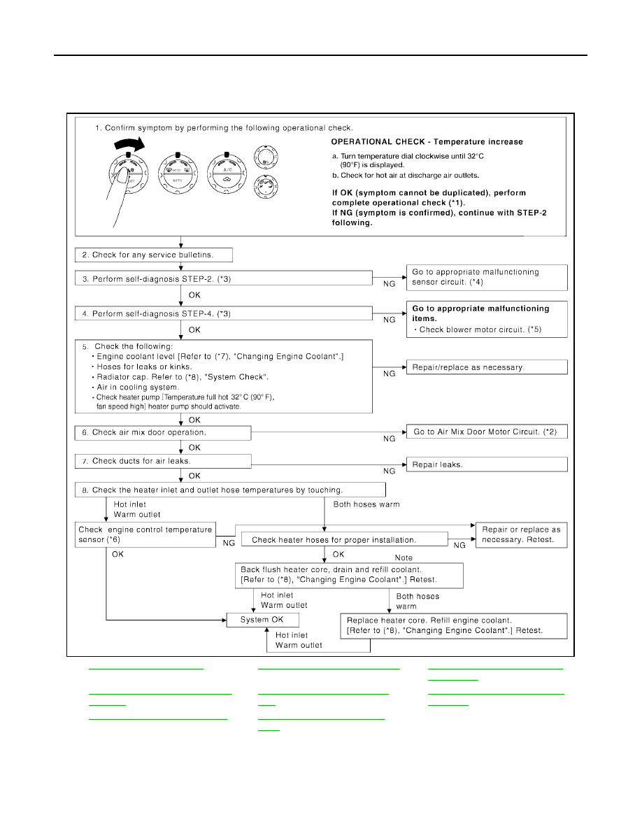
ATC-112
TROUBLE DIAGNOSIS
Revision: May 2004
2004 Quest
Insufficient Heating
EJS001NT
SYMPTOM: Insufficient heating
INSPECTION FLOW
*1
.
*2
ATC-62, "Air Mix Door Motor Circuit"
. *3
ATC-50, "A/C System Self-diagno-
sis Function"
.
*4
ATC-50, "A/C System Self-diagnosis
Function"
.
*5
ATC-78, "Front Blower Motor Cir-
cuit"
.
*6
EC-186, "DTC P0117, P0118 ECT
SENSOR"
*7
MA-14, "Changing Engine Coolant"
*8
WJIA1026E
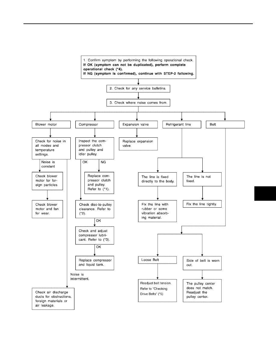
TROUBLE DIAGNOSIS
ATC-113
C
D
E
F
G
H
I
K
L
M
A
B
ATC
Revision: May 2004
2004 Quest
Noise
EJS001NU
SYMPTOM: Noise
INSPECTION FLOW
WJIA0473E

ATC-114
TROUBLE DIAGNOSIS
Revision: May 2004
2004 Quest
*1
.
*2
*3
ATC-22, "Maintenance of Lubricant
Quantity in Compressor"
.
*4
*5
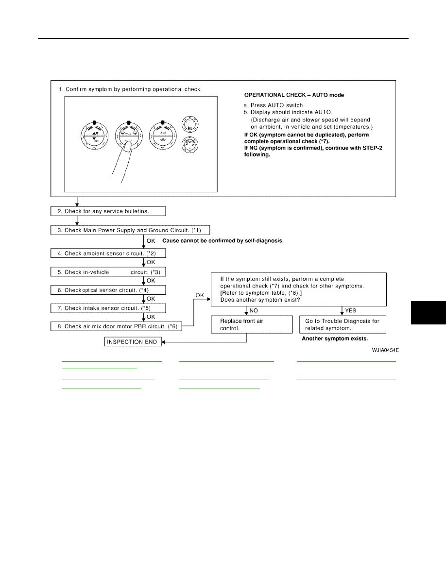
TROUBLE DIAGNOSIS
ATC-115
C
D
E
F
G
H
I
K
L
M
A
B
ATC
Revision: May 2004
2004 Quest
Self-diagnosis
EJS001NV
SYMPTOM: Self-diagnosis cannot be performed.
INSPECTION FLOW
*1
ATC-55, "Power Supply and Ground
Circuit for Front Air Control"
.
*2
ATC-117, "Ambient Sensor Circuit"
*3
ATC-120, "In-vehicle Sensor Circuit"
.
*4
ATC-123, "Optical Sensor Circuit"
.
*5
ATC-125, "Intake Sensor Circuit"
*6
ATC-62, "Air Mix Door Motor Circuit"
*7
*8
.
WJIA0454E
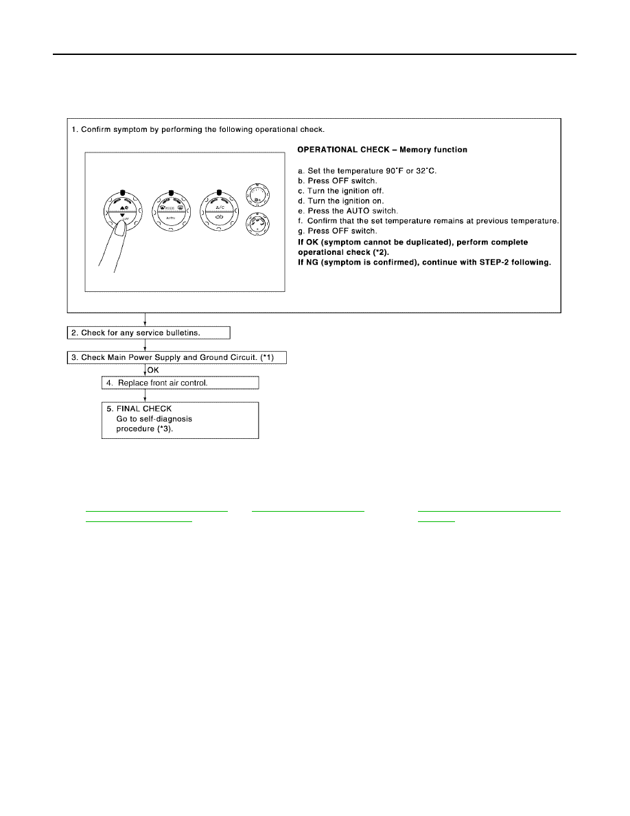
ATC-116
TROUBLE DIAGNOSIS
Revision: May 2004
2004 Quest
Memory Function
EJS001NW
SYMPTOM: Memory function does not operate.
INSPECTION FLOW
*1
ATC-55, "Power Supply and Ground
Circuit for Front Air Control"
*2
.
*3
ATC-50, "A/C System Self-diagnosis
Function"
WJIA0455E
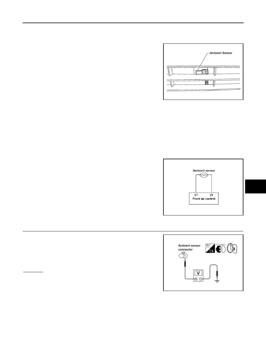
TROUBLE DIAGNOSIS
ATC-117
C
D
E
F
G
H
I
K
L
M
A
B
ATC
Revision: May 2004
2004 Quest
Ambient Sensor Circuit
EJS001NX
COMPONENT DESCRIPTION
Ambient Sensor
The ambient sensor is attached on the radiator core support (left
side). It detects ambient temperature and converts it into a resis-
tance value which is then input into the front air control.
AMBIENT TEMPERATURE INPUT PROCESS
The front air control includes a processing circuit for the ambient sensor input. However, when the tempera-
ture detected by the ambient sensor increases quickly, the processing circuit retards the front air control func-
tion. It only allows the front air control to recognize an ambient temperature increase of 0.33
°
C (0.6
°
F) per 100
seconds.
This prevents constant adjustments due to momentary conditions, such as stopping after high speed driving.
Although the actual ambient temperature has not changed, the temperature detected by the ambient sensor
will increase. This is because the heat from the engine compartment can radiate to the front grille area, loca-
tion of the ambient sensor.
DIAGNOSTIC PROCEDURE FOR AMBIENT SENSOR
SYMPTOM: Ambient sensor circuit is open or shorted. (40 or 41 is
indicated on front air control As a result of conducting the front air
control self-diagnosis)
1.
CHECK VOLTAGE BETWEEN AMBIENT SENSOR AND GROUND
1.
Disconnect ambient sensor connector.
2.
Turn ignition switch ON.
3.
Check voltage between ambient sensor harness connector E1
terminal 1 (O/B) and ground.
OK or NG
OK
>> GO TO 2.
NG
>> GO TO 4.
WJIA0338E
WJIA0456E
Approx. 5V
WJIA0526E
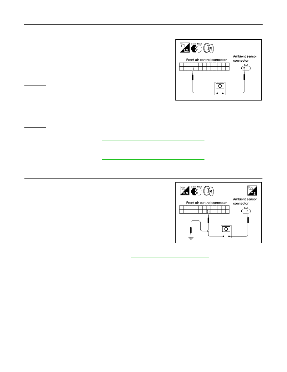
ATC-118
TROUBLE DIAGNOSIS
Revision: May 2004
2004 Quest
2.
CHECK CIRCUIT CONTINUITY BETWEEN AMBIENT SENSOR AND FRONT AIR CONTROL
1.
Turn ignition switch OFF.
2.
Disconnect front air control connector.
3.
Check continuity between ambient sensor harness connector
E1 terminal 2 (GR/R) and front air control harness connector
M49 terminal 17 (GR/R).
OK or NG
OK
>> GO TO 3.
NG
>> Repair harness or connector.
3.
CHECK AMBIENT SENSOR
.
OK or NG
OK
>> 1. Replace front air control. Refer to
2. Go to self-diagnosis
ATC-50, "A/C System Self-diagnosis Function"
and perform self-diagno-
sis.
NG
>> 1. Replace ambient sensor.
2. Go to self-diagnosis
ATC-50, "A/C System Self-diagnosis Function"
and perform self-diagno-
sis.
4.
CHECK CIRCUIT CONTINUITY BETWEEN AMBIENT SENSOR AND FRONT AIR CONTROL
1.
Turn ignition switch OFF.
2.
Disconnect front air control connector.
3.
Check continuity between ambient sensor harness connector
E1 terminal 1 (O/B) and front air control harness connector M49
terminal 21 (O/B).
4.
Check continuity between ambient sensor harness connector
E1 terminal 1 (O/B) and ground.
OK or NG
OK
>> 1. Replace front air control. Refer to
2. Go to self-diagnosis
ATC-50, "A/C System Self-diagnosis Function"
sis.
NG
>> Repair harness or connector.
Continuity should exist.
WJIA0457E
Continuity should exist.
Continuity should not exist.
WJIA0458E
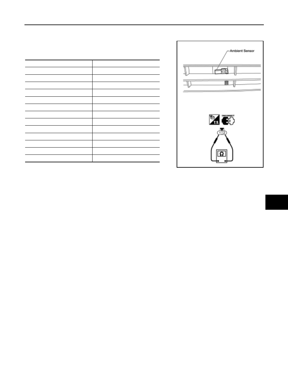
TROUBLE DIAGNOSIS
ATC-119
C
D
E
F
G
H
I
K
L
M
A
B
ATC
Revision: May 2004
2004 Quest
COMPONENT INSPECTION
Ambient Sensor
After disconnecting ambient sensor connector, measure resistance
between terminals 2 and 1 at sensor component side, using the table
below.
If NG, replace ambient sensor.
Temperature
°
C (
°
F)
Resistance k
Ω
−
15 (5)
12.73
−
10 (14)
9.92
−
5 (23)
7.80
0 (32)
6.19
5 (41)
4.95
10 (50)
3.99
15 (59)
3.24
20 (68)
2.65
25 (77)
2.19
30 (86)
1.81
35 (95)
1.51
40 (104)
1.27
45 (113)
1.07
WJIA0527E
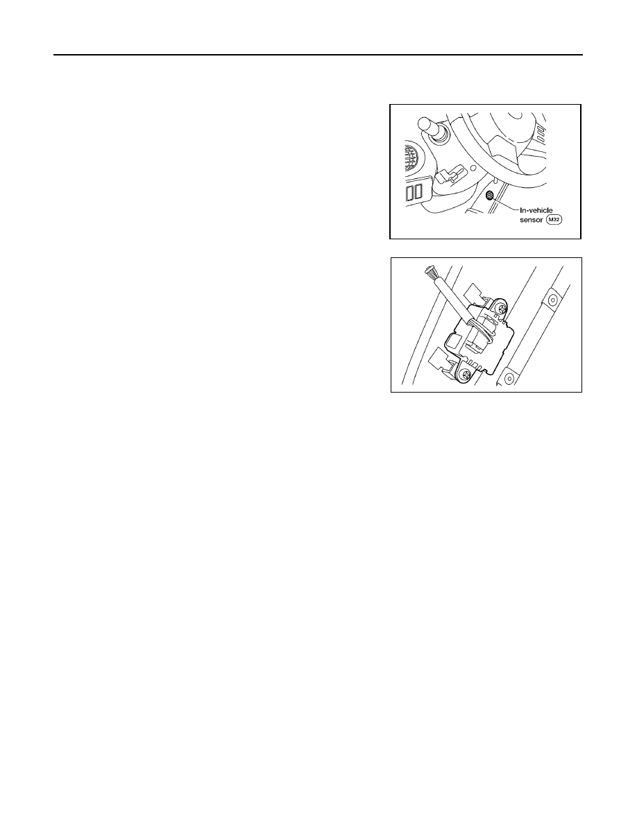
ATC-120
TROUBLE DIAGNOSIS
Revision: May 2004
2004 Quest
In-vehicle Sensor Circuit
EJS001NY
COMPONENT DESCRIPTION
In-vehicle Sensor
The in-vehicle sensor is located on instrument lower driver panel. It
converts variations in temperature of passenger compartment air
(drawn in through the integrated fan) into a resistance value. It is
then input into the front air control.
WJIA0459E
LJIA0088E
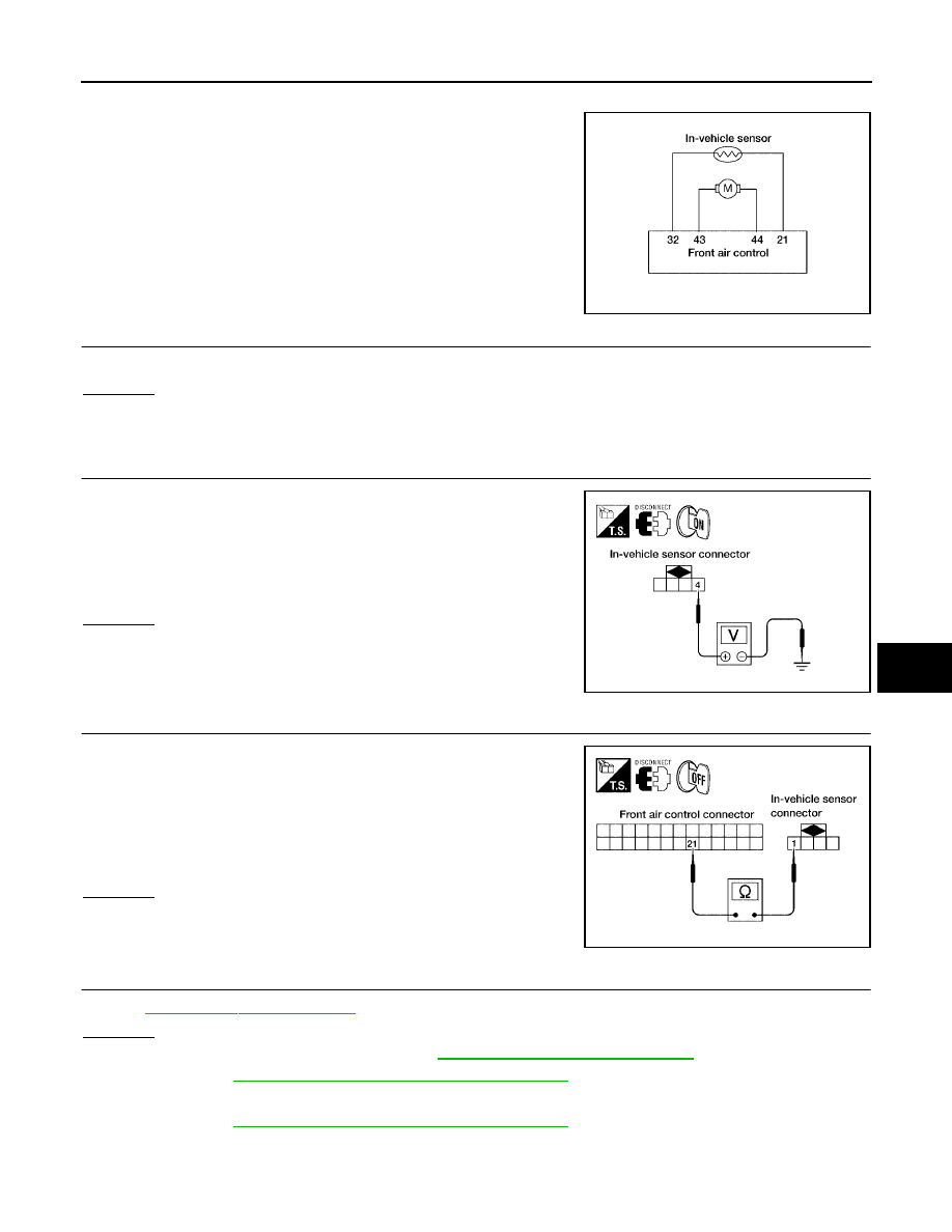
TROUBLE DIAGNOSIS
ATC-121
C
D
E
F
G
H
I
K
L
M
A
B
ATC
Revision: May 2004
2004 Quest
DIAGNOSTIC PROCEDURE FOR IN-VEHICLE SENSOR
SYMPTOM: In-vehicle sensor circuit is open or shorted. (30 or 31 is
indicated on front air control as a result of conducting Self-diagnosis.
1.
CHECK VOLTAGE BETWEEN IN-VEHICLE SENSOR AND GROUND
Are diagnostic codes 44 or 46 present?
Yes or No
Yes
>> GO TO 6.
No
>> GO TO 2.
2.
CHECK VOLTAGE BETWEEN IN-VEHICLE SENSOR AND GROUND
1.
Disconnect in-vehicle sensor connector.
2.
Turn ignition switch ON.
3.
Check voltage between in-vehicle sensor harness connector
M32 terminal 4 (BR/W) and ground.
OK or NG
OK
>> GO TO 3.
NG
>> GO TO 5.
3.
CHECK CIRCUIT CONTINUITY BETWEEN IN-VEHICLE SENSOR AND FRONT AIR CONTROL
1.
Turn ignition switch OFF.
2.
Disconnect front air control connector.
3.
Check continuity between in-vehicle sensor harness connector
M32 terminal 1 (O/B) and front air control harness connector
M49 terminal 21 (O/B).
OK or NG
OK
>> GO TO 4.
NG
>> Repair harness or connector.
4.
CHECK IN-VEHICLE SENSOR
Refer to
OK or NG
OK
>> 1. Replace front air control. Refer to
.
2. Go to
ATC-50, "A/C System Self-diagnosis Function"
and perform self-diagnosis.
NG
>> 1. Replace in-vehicle sensor.
2. Go to
ATC-50, "A/C System Self-diagnosis Function"
and perform self-diagnosis.
WJIA0460E
Approx. 5V.
LJIA0089E
Continuity should exist.
LJIA0090E
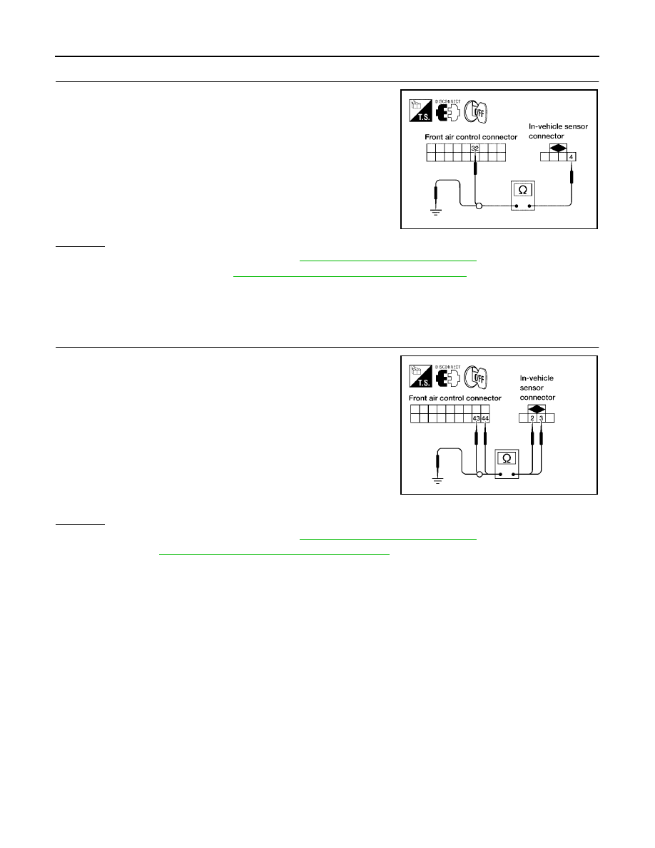
ATC-122
TROUBLE DIAGNOSIS
Revision: May 2004
2004 Quest
5.
CHECK CIRCUIT CONTINUITY BETWEEN IN-VEHICLE SENSOR AND FRONT AIR CONTROL
1.
Turn ignition switch OFF.
2.
Disconnect front air control connector.
3.
Check continuity between in-vehicle sensor harness connector
M32 terminal 4 (BR/W) and front air control harness connector
M50 terminal 32 (BR/W).
4.
Check continuity between in-vehicle sensor harness connector
M32 terminal 4 (BR/W) and ground.
OK or NG
OK
>> 1. Replace front air control. Refer to
2. Go to self-diagnosis
ATC-50, "A/C System Self-diagnosis Function"
and perform self-diagno-
sis.
NG
>> Repair harness or connector.
6.
CHECK CIRCUIT CONTINUITY BETWEEN IN-VEHICLE SENSOR MOTOR AND FRONT AIR CON-
TROL (SELF-DIAGNOSIS CODES 44 OR 46)
1.
Turn ignition switch OFF.
2.
Disconnect front air control connector and in-vehicle sensor con-
nector.
3.
Check continuity between in-vehicle sensor harness connector
M32 terminal 2 (W/R) and 3 (BR) and front air control harness
connector M50 terminal 44 (W/R) and 43 (BR) .
4.
Check continuity between in-vehicle sensor harness connector
M32 terminal 2 (W/R) and 3 (BR) and ground.
OK or NG
OK
>> 1. Replace front air control. Refer to
2. Go to
ATC-50, "A/C System Self-diagnosis Function"
and perform self-diagnosis.
NG
>> Repair harness or connector.
Continuity should exist.
Continuity should not exist.
LJIA0091E
Continuity should exist.
Continuity should not exist.
LJIA0093E
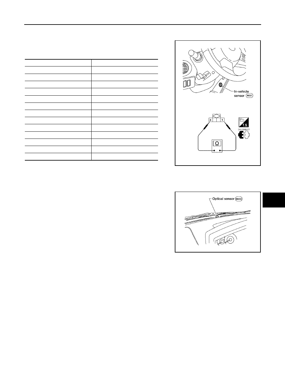
TROUBLE DIAGNOSIS
ATC-123
C
D
E
F
G
H
I
K
L
M
A
B
ATC
Revision: May 2004
2004 Quest
COMPONENT INSPECTION
In-vehicle Sensor
After disconnecting in-vehicle sensor connector, measure resistance
between terminals 1 and 2 at sensor component side, using the table
below.
If NG, replace in-vehicle sensor.
Optical Sensor Circuit
EJS001NZ
COMPONENT DESCRIPTION
The optical sensor is located on the passenger side defroster grille. It
detects sunload entering through windshield by means of a photo
diode. The sensor converts the sunload into a current value which is
then input into the front air control
OPTICAL INPUT PROCESS
The front air control also includes a processing circuit which averages the variations in detected sunload over
a period of time. This prevents adjustments in the ATC system operation due to small or quick variations in
detected sunload.
For example, consider driving along a road bordered by an occasional group of large trees. The sunload
detected by the optical sensor will vary whenever the trees obstruct the sunlight. The processing circuit aver-
ages the detected sunload over a period of time, so that the (insignificant) effect of the trees momentarily
obstructing the sunlight does not cause any change in the ATC system operation. On the other hand, shortly
after entering a long tunnel, the system will recognize the change in sunload, and the system will react accord-
ingly.
Temperature
°
C (
°
F)
Resistance k
Ω
−
15 (5)
21.40
−
10 (14)
16.15
−
5 (23)
12.29
0 (32)
9.41
5 (41)
7.27
10 (50)
5.66
15 (59)
4.45
20 (68)
3.51
25 (77)
2.79
30 (86)
2.24
35 (95)
1.80
40 (104)
1.45
45 (113)
1.18
LJIA0092E
LJIA0094E
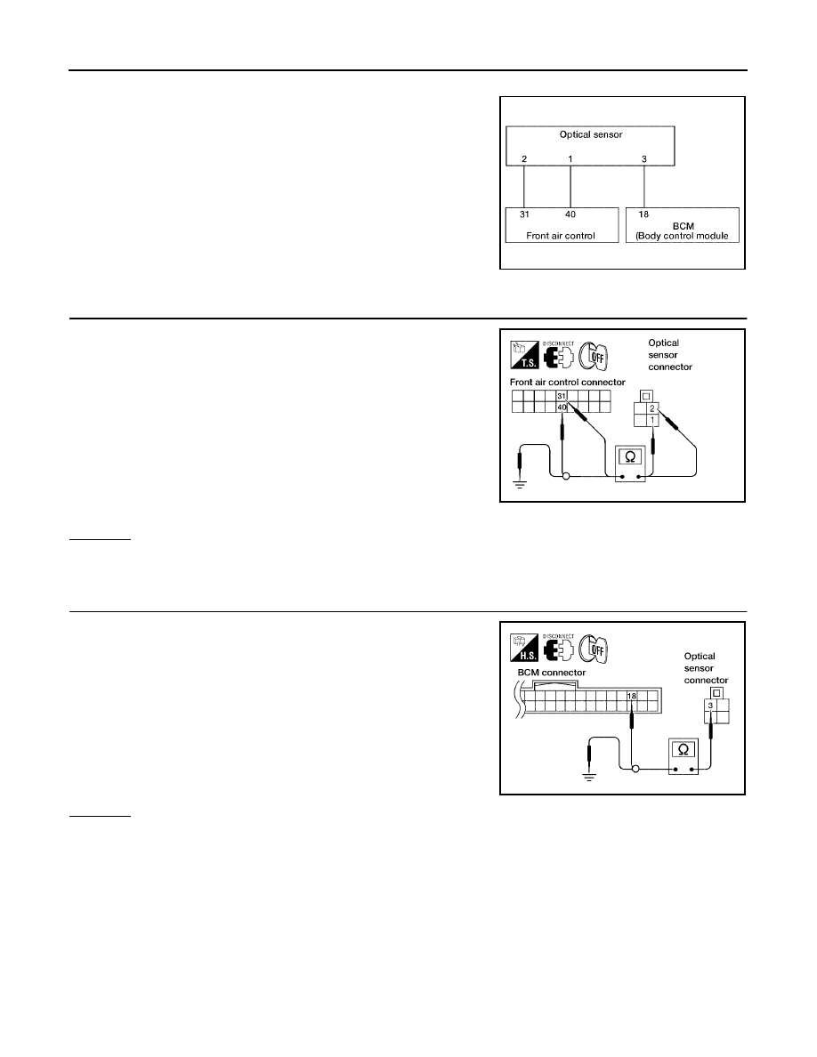
ATC-124
TROUBLE DIAGNOSIS
Revision: May 2004
2004 Quest
DIAGNOSTIC PROCEDURE FOR OPTICAL SENSOR
SYMPTOM: Optical sensor circuit is open or shorted. [50 (driver) or
52 (passenger) is indicated on front air control as a result of conduct-
ing self-diagnosis.]
1.
CHECK CIRCUIT CONTINUITY BETWEEN OPTICAL SENSOR AND FRONT AIR CONTROL
1.
Turn ignition switch OFF.
2.
Disconnect front air control connector and optical sensor con-
nector.
3.
Check continuity between optical sensor harness connector
M402 terminal 1 (LG) and 2 (SB) and front air control harness
connector M50 terminal 40 (LG) and 31 (SB).
4.
Check continuity between optical sensor harness connector
M32 terminal 1 (LG) and 2 (SB) and ground.
OK or NG
OK
>> GO TO 2.
NG
>> Repair harness or connector.
2.
CHECK CIRCUIT CONTINUITY BETWEEN OPTICAL SENSOR AND BCM
1.
Turn ignition switch OFF.
2.
Disconnect BCM connector and optical sensor connector.
3.
Check continuity between optical sensor harness connector
M402 terminal 3 (P) and BCM harness connector M18 terminal
18 (P).
4.
Check continuity between optical sensor harness connector
M402 terminal 3 (P) and ground.
OK or NG
OK
>> Replace optical sensor.
NG
>> Repair harness or connector.
WJIA0461E
Continuity should exist.
Continuity should not exist.
WJIA0474E
Continuity should exist.
Continuity should not exist.
WJIA0475E
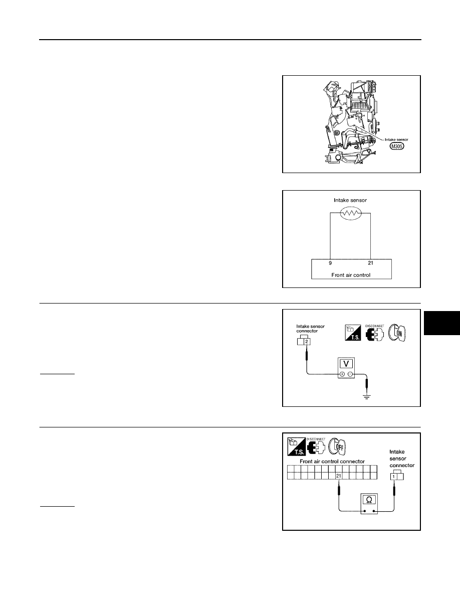
TROUBLE DIAGNOSIS
ATC-125
C
D
E
F
G
H
I
K
L
M
A
B
ATC
Revision: May 2004
2004 Quest
Intake Sensor Circuit
EJS001O0
COMPONENT DESCRIPTION
Intake Sensor
The intake sensor is located on the heater & cooling unit. It converts
temperature of air after it passes through the evaporator into a resis-
tance value which is then input to the front air control.
DIAGNOSTIC PROCEDURE FOR INTAKE SENSOR
SYMPTOM: Intake sensor circuit is open or shorted. (56 or 57 is indi-
cated on front air control as a result of conducting Self-diagnosis).
1.
CHECK VOLTAGE BETWEEN INTAKE SENSOR AND GROUND
1.
Disconnect intake sensor connector.
2.
Turn ignition switch ON.
3.
Check voltage between intake sensor harness connector M305
terminal 2 (R/W) and ground.
OK or NG
OK
>> GO TO 2.
NG
>> GO TO 4.
2.
CHECK CIRCUIT CONTINUITY BETWEEN INTAKE SENSOR AND FRONT AIR CONTROL
1.
Turn ignition switch OFF.
2.
Disconnect front air control connector.
3.
Check continuity between intake sensor harness connector
M305 terminal 1 (O/B) and front air control harness connector
M49 terminal 21 (O/B).
OK or NG
OK
>> GO TO 3.
NG
>> Repair harness or connector.
WJIA0482E
WJIA0464E
Approx. 5V
WJIA0465E
Continuity should exist.
WJIA0466E
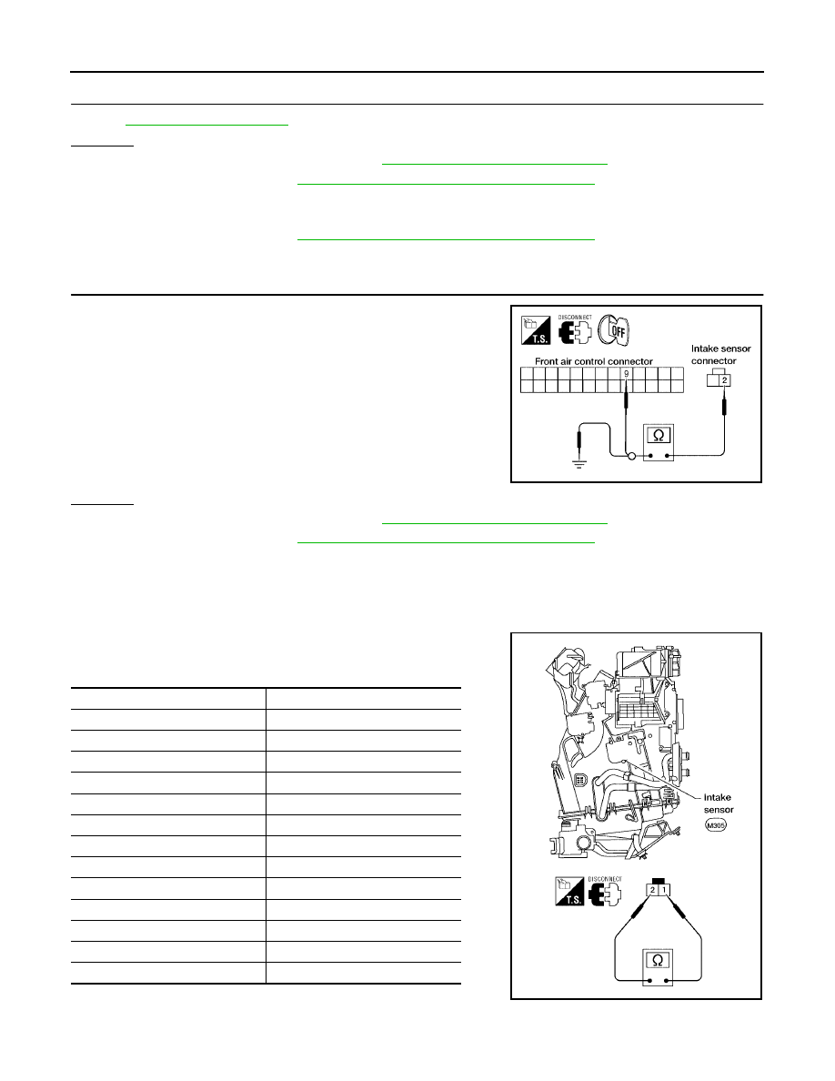
ATC-126
TROUBLE DIAGNOSIS
Revision: May 2004
2004 Quest
3.
CHECK INTAKE SENSOR
OK or NG
OK
>> 1. Replace front air control. Refer to
2. Go to self-diagnosis
ATC-50, "A/C System Self-diagnosis Function"
and perform self-diagno-
sis.
NG
>> 1. Replace intake sensor.
2. Go to self-diagnosis
ATC-50, "A/C System Self-diagnosis Function"
and perform self-diagno-
sis.
4.
CHECK CIRCUIT CONTINUITY BETWEEN INTAKE SENSOR AND FRONT AIR CONTROL
1.
Turn ignition switch OFF.
2.
Disconnect front air control connector.
3.
Check continuity between intake sensor harness connector
M305 terminal 2 (R/W) and front air control harness connector
M49 terminal 9 (R/W).
4.
Check continuity between intake sensor harness connector
M305 terminal 2 (R/W) and ground.
OK or NG
OK
>> 1. Replace front air control. Refer to
2. Go to self-diagnosis
ATC-50, "A/C System Self-diagnosis Function"
and perform self-diagno-
sis.
NG
>> Repair harness or connector.
COMPONENT INSPECTION
Intake Sensor
After disconnecting intake sensor connector, measure resistance
between terminals 1 and 2 at sensor harness side, using the table
below.
If NG, replace intake sensor.
Continuity should exist.
Continuity should not exist.
LJIA0125E
Temperature
°
C (
°
F)
Resistance k
Ω
−
15 (5)
209.0
−
10 (14)
160.0
−
5 (23)
123.0
0 (32)
95.8
5 (41)
74.9
10 (50)
58.9
15 (59)
46.7
20 (68)
37.3
25 (77)
30.0
30 (86)
24.2
35 (95)
19.7
40 (104)
16.1
45 (113)
13.2
WJIA0978E
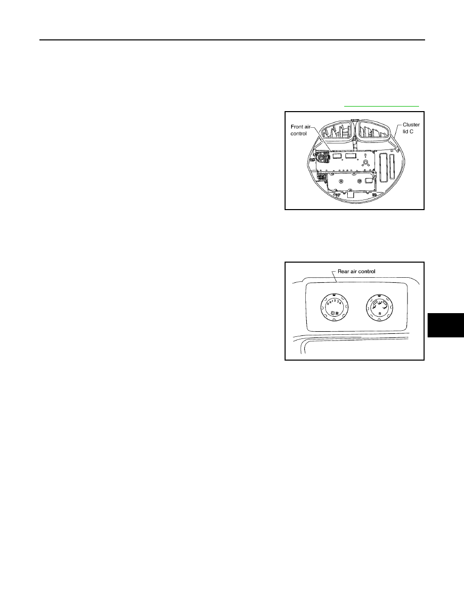
CONTROL UNIT
ATC-127
C
D
E
F
G
H
I
K
L
M
A
B
ATC
Revision: May 2004
2004 Quest
CONTROL UNIT
PFP:27500
Removal and Installation
EJS001O1
FRONT AIR CONTROL
Removal
1.
Remove the five control knobs from the control unit.
2.
Remove cluster lid C, disconnect the front air control electrical connector. Refer to
.
3.
Remove the screws securing the front air control to cluster lid C.
4.
Remove the front air control.
Installation
Installation is the reverse order of removal.
REAR AIR CONTROL
Removal
1.
Remove the rear air control from the headliner, located over the
sliding door, RH.
2.
Disconnect the rear air control electrical connector and remove
the rear air control.
Installation
Installation is in the reverse order of removal.
WJIA0425E
LJIA0030E
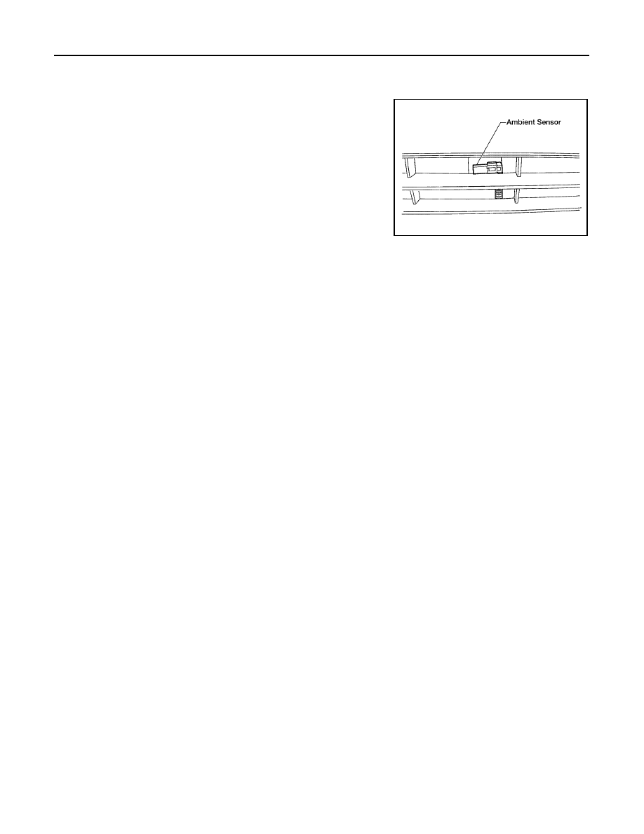
ATC-128
AMBIENT SENSOR
Revision: May 2004
2004 Quest
AMBIENT SENSOR
PFP:27722
Removal and Installation
EJS001O2
1.
Disconnect the ambient sensor connector.
NOTE:
The ambient sensor is located behind the front bumper opening,
in front of the condenser.
2.
Release the ambient sensor clip and then remove the ambient
sensor.
3.
Installation is in the reverse order of removal.
WJIA0341E
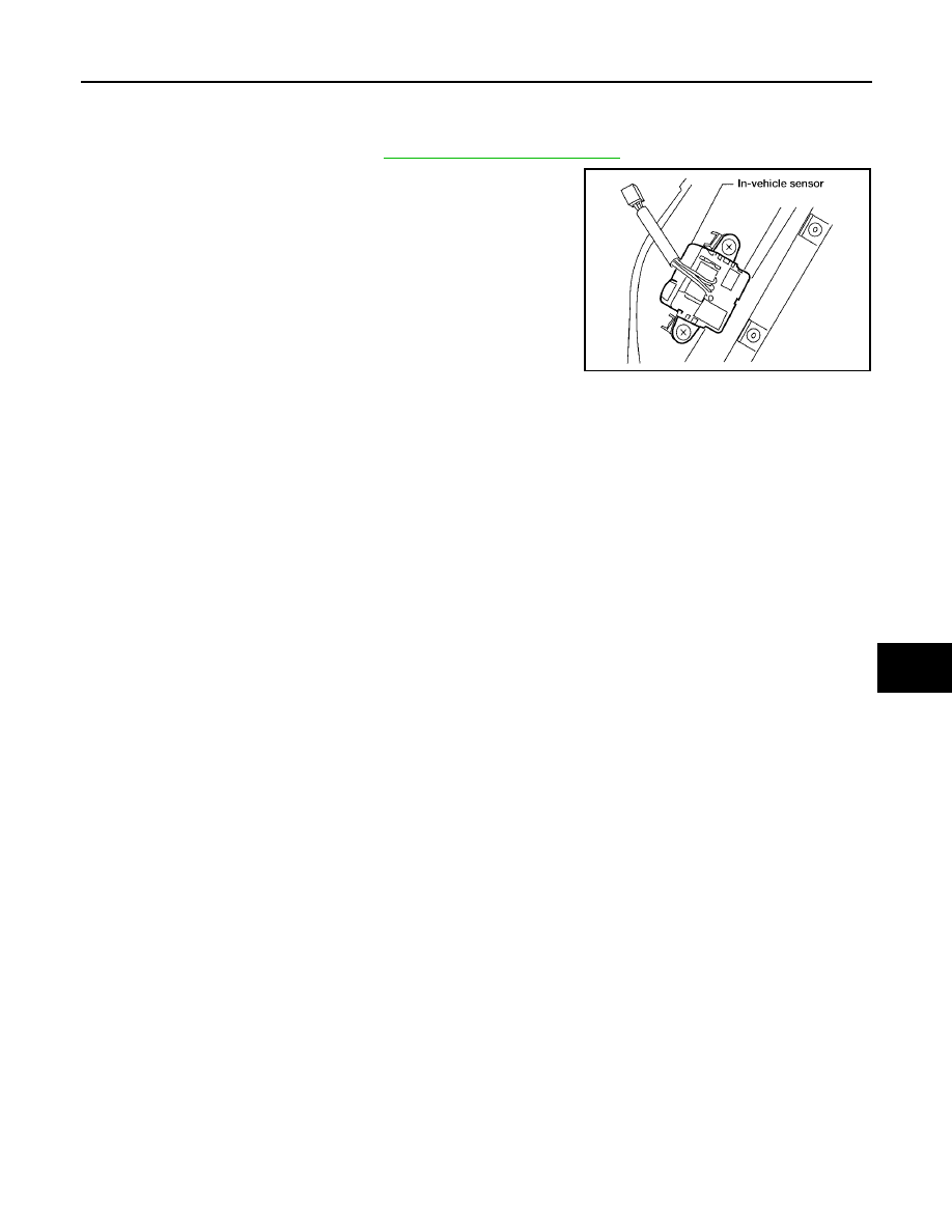
IN-VEHICLE SENSOR
ATC-129
C
D
E
F
G
H
I
K
L
M
A
B
ATC
Revision: May 2004
2004 Quest
IN-VEHICLE SENSOR
PFP:27720
Removal and Installation
EJS001O3
1.
Remove the center console. Refer to
IP-11, "Removal and Installation"
2.
Remove the two screws and remove the in-vehicle sensor.
3.
Installation is in the reverse order of removal.
LJIA0059E

ATC-130
OPTICAL SENSOR
Revision: May 2004
2004 Quest
OPTICAL SENSOR
PFP:28576
Removal and Installation
EJS001O4
The optical sensor is located in the top center of the instrument panel. Refer to
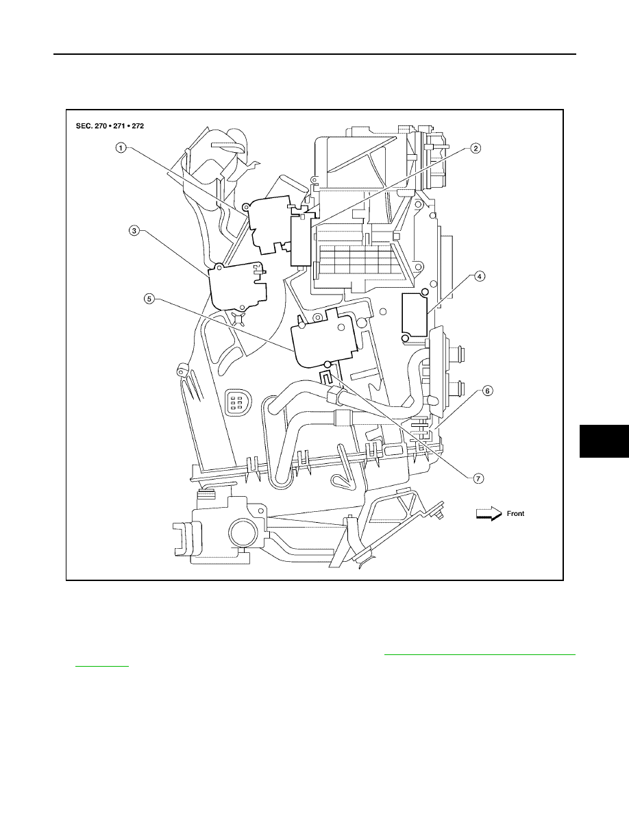
INTAKE SENSOR
ATC-131
C
D
E
F
G
H
I
K
L
M
A
B
ATC
Revision: May 2004
2004 Quest
INTAKE SENSOR
PFP:27723
Removal and Installation
EJS001U0
Intake Sensor
REMOVAL
1.
Remove the instrument lower panel RH and glove box. Refer to
IP-13, "Instrument Lower Panel RH and
2.
Disconnect the intake sensor electrical connector.
3.
Twist the intake sensor to remove the intake sensor from the front heater and cooling unit assembly.
INSTALLATION
Installation is in the reverse order of removal.
WJIA0514E
1.
Defroster door motor
2.
Intake door motor (passenger)
3.
Mode door motor
4.
Variable blower control
5.
Air mix door motor (passenger)
6.
Front heater and cooling unit assembly
7.
Intake sensor
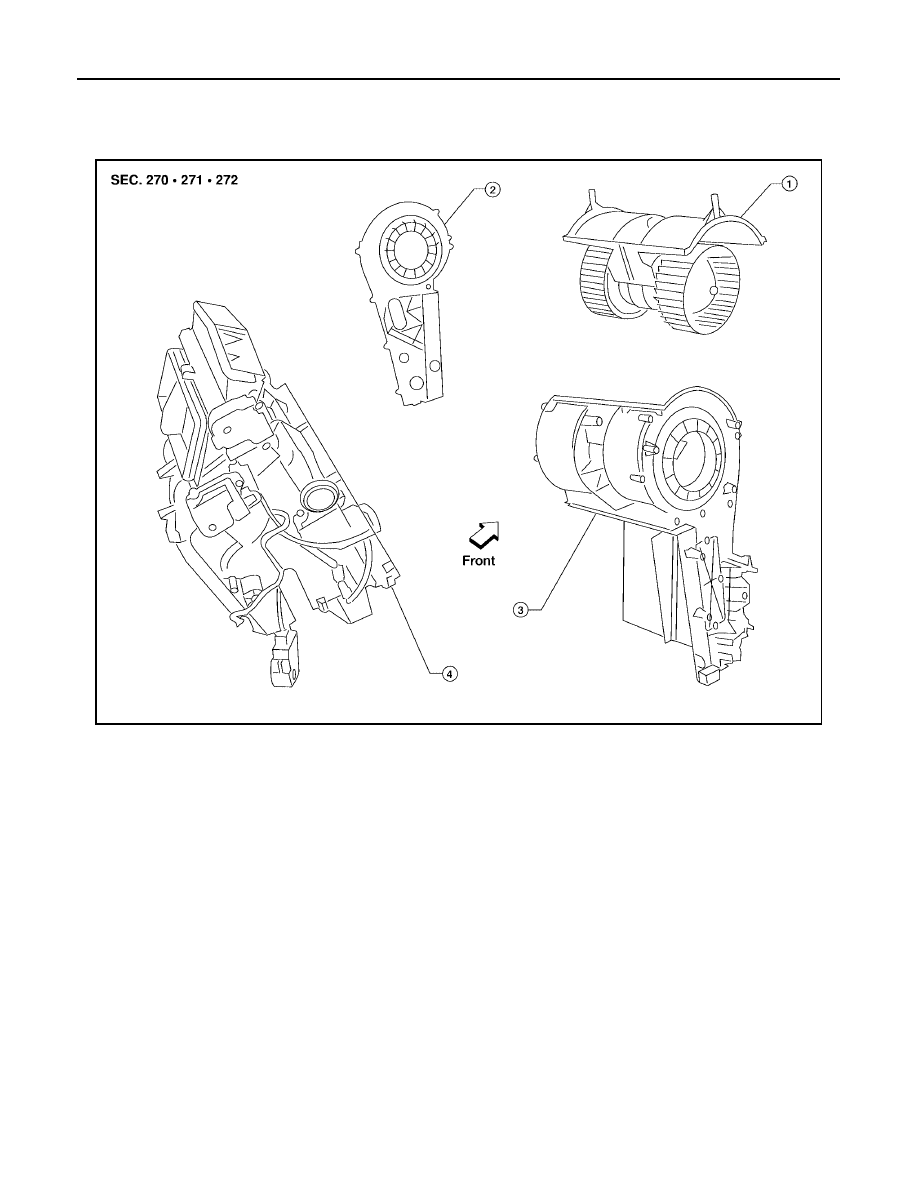
ATC-132
BLOWER MOTOR
Revision: May 2004
2004 Quest
BLOWER MOTOR
PFP:27226
Components
EJS001U2
Front Blower Motor
LJIA0017E
1.
Front blower motor
2.
Blower motor side cover
3.
Blower motor case
4.
Heater core and evaporator case
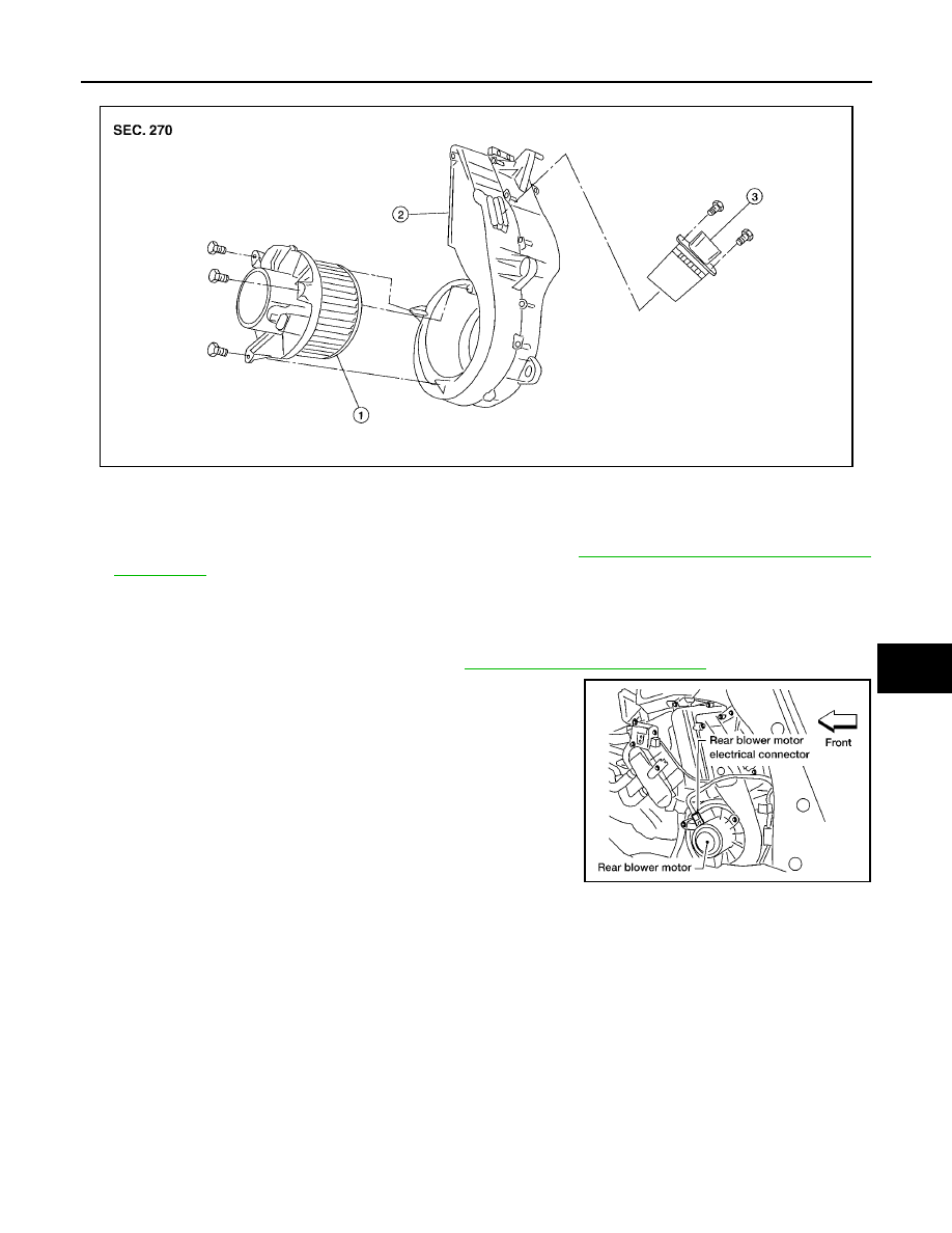
BLOWER MOTOR
ATC-133
C
D
E
F
G
H
I
K
L
M
A
B
ATC
Revision: May 2004
2004 Quest
Rear Blower Motor
Removal and Installation
EJS001O7
FRONT BLOWER MOTOR
1.
Remove the front heater and cooling unit assembly. Refer to
ATC-135, "HEATER & COOLING UNIT
2.
Disassemble the front heater and cooling unit case to remove the front blower motor.
3.
Installation is in the reverse order of removal.
REAR BLOWER MOTOR
1.
Remove the rear RH interior trim panel. Refer to
2.
Disconnect the blower motor electrical connector.
3.
Remove the three screws and remove the blower motor.
4.
Installation is in the reverse order of removal.
LJIA0055E
1.
Rear blower motor
2.
Rear blower motor case
3.
Rear blower motor resistor
LJIA0056E
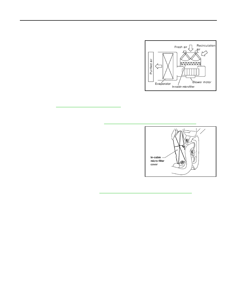
ATC-134
IN-CABIN MICROFILTER
Revision: May 2004
2004 Quest
IN-CABIN MICROFILTER
PFP:27277
Removal and Installation
EJS001O9
FUNCTION
The air inside the passenger compartment is filtered by the in-cabin
microfilters when the heater or A/C controls are set on either the
recirculation or fresh mode. The two in-cabin microfilters are located
in the front heater and cooling unit assembly. The rear heater and
cooling unit assembly only draws in air from the passenger compart-
ment to recirculate into the passenger compartment, so the rear
heater and cooling unit assembly is not equipped with in-cabin
microfilters.
REPLACEMENT TIMING
Replacement of the two in-cabin microfilters is recommended on a regular interval depending on the driving
conditions. Refer to
. It may also be necessary to replace the two in-cabin
microfilters as part of a component replacement if the in-cabin microfilters are damaged.
REPLACEMENT PROCEDURES
1.
Remove the glove box assembly. Refer to
IP-13, "Instrument Lower Panel RH and Glove Box"
2.
Remove the three screws and remove the in-cabin microfilter
cover.
3.
Remove the in-cabin microfilters from the front heater and cool-
ing unit assembly.
4.
Install the in-cabin microfilters, replacing the two in-cabin micro-
filters with new filters, into the front heater and cooling unit
assembly.
CAUTION:
When installing the two new in-cabin microfilters make sure
that the filters are facing in the direction indicated by the
direction arrow for the air flow. The direction arrow is
printed on the side of the in-cabin microfilters.
5.
Install the in-cabin microfilter cover.
6.
Install the glove box assembly. Refer to
IP-13, "Instrument Lower Panel RH and Glove Box"
LJIA0012E
LJIA0058E
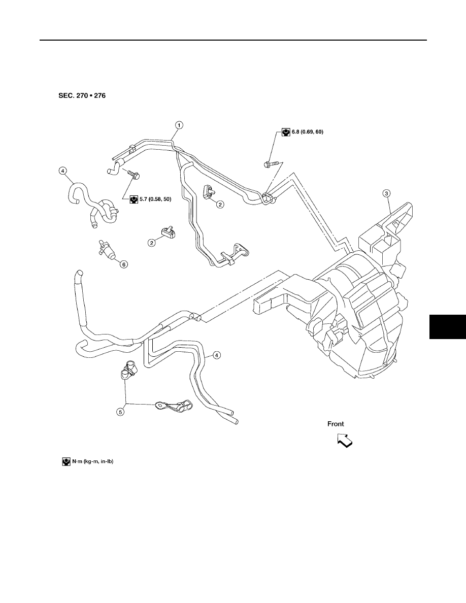
HEATER & COOLING UNIT ASSEMBLY
ATC-135
C
D
E
F
G
H
I
K
L
M
A
B
ATC
Revision: May 2004
2004 Quest
HEATER & COOLING UNIT ASSEMBLY
PFP:27110
Components
EJS001U8
Front Heater and Cooling Unit Assembly
LJIA0067E
1.
High/low pressure pipe
2.
High/low pressure pipe bracket
3.
Front heater and cooling unit
assembly
4.
Front heater core pipe and hose
assembly
5.
Front heater core pipe bracket
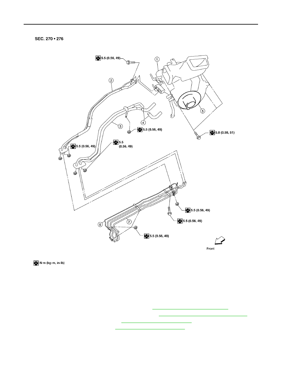
ATC-136
HEATER & COOLING UNIT ASSEMBLY
Revision: May 2004
2004 Quest
Rear Heater and Cooling Unit Assembly
Removal and Installation
EJS001OA
FRONT HEATER AND COOLING UNIT ASSEMBLY
1.
Discharge the refrigerant from the A/C system. Refer to
ATC-158, "Discharging Refrigerant"
2.
Drain the coolant from the engine cooling system. Refer to
MA-14, "DRAINING ENGINE COOLANT"
3.
Remove the cowl top extension. Refer to
EI-18, "Removal and Installation"
.
4.
Remove the exhaust system. Refer to
EX-3, "Removal and Installation"
5.
Disconnect the front heater hoses from the front heater core.
6.
Disconnect the high/low pressure pipe from the front expansion valve.
7.
Move the two front seats to the rearmost position on the seat track.
LJIA0066E
1.
Rear heater and cooling unit assembly
2.
Rear A/C pipes
3.
Rear heater core pipes
4.
Rear heater core hose
5.
Rear blower motor
6.
Underfloor rear A/C pipes
7.
Underfloor rear heater core pipes
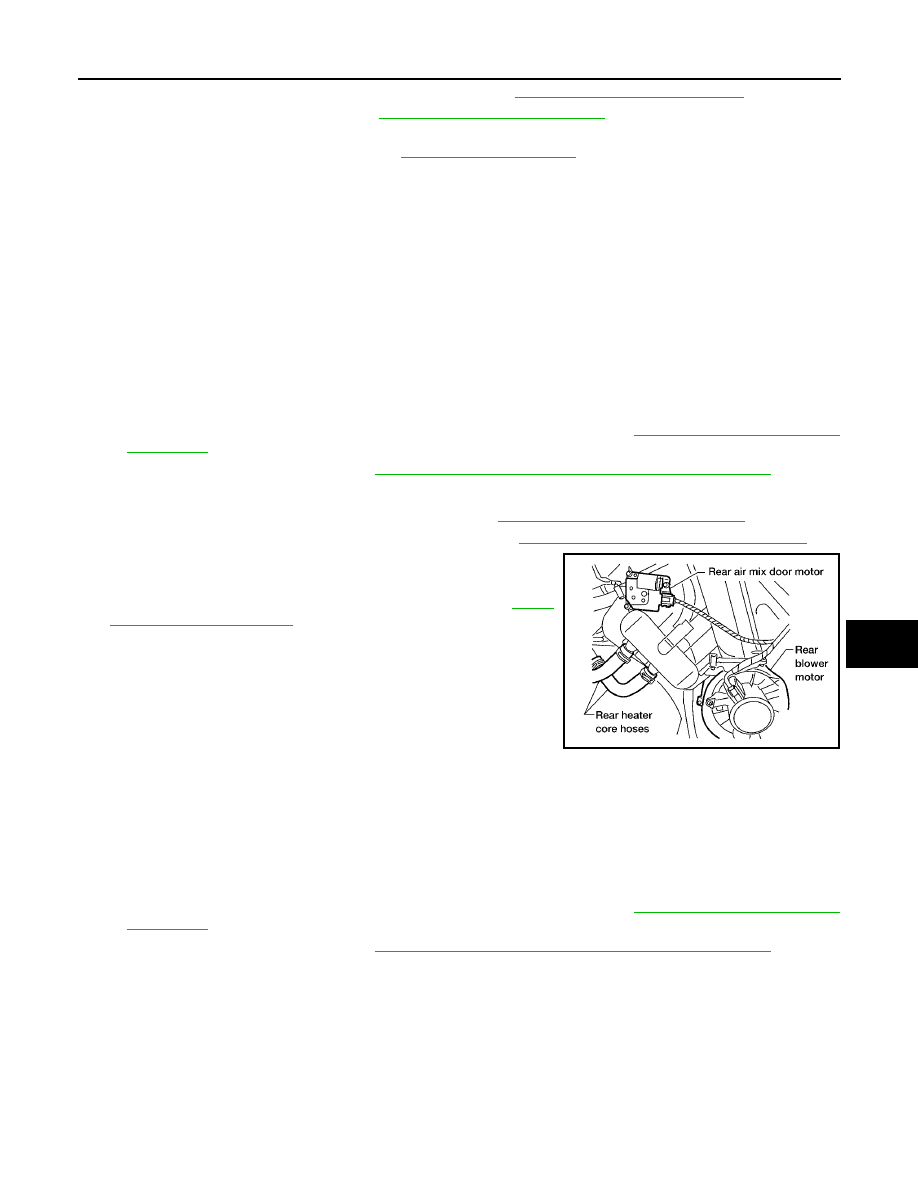
HEATER & COOLING UNIT ASSEMBLY
ATC-137
C
D
E
F
G
H
I
K
L
M
A
B
ATC
Revision: May 2004
2004 Quest
8.
Remove the instrument panel and console panel. Refer to
IP-10, "Removal and Installation"
.
9.
Remove the steering column. Refer to
PS-9, "Removal and Installation"
.
10. Disconnect the instrument panel wire harness at the RH and LH in-line connector brackets, and the fuse
block (J/B) electrical connectors. Refer to
11. Disconnect the steering member from each side of the vehicle body.
12. Remove the front heater and cooling unit assembly with it attached to the steering member, from the vehi-
cle.
CAUTION:
Use care not to damage the seats and interior trim panels when removing the front heater and
cooling unit assembly with it attached to the steering member.
13. Remove the front heater and cooling unit assembly from the steering member.
14. Installation is in the reverse order of removal.
CAUTION:
●
Replace the O-ring of the low-pressure flexible hose and high-pressure flexible hose with a new
one, and apply compressor oil to it when installing it.
●
After charging the refrigerant, check for leaks.
NOTE:
●
Fill the engine cooling system with the specified coolant mixture. Refer to
●
Recharge the A/C system. Refer to
ATC-158, "Evacuating System and Charging Refrigerant"
.
REAR HEATER AND COOLING UNIT ASSEMBLY
1.
Discharge the refrigerant from the A/C system. Refer to
ATC-158, "Discharging Refrigerant"
.
2.
Drain the coolant from the engine cooling system. Refer to
MA-14, "DRAINING ENGINE COOLANT"
3.
Disconnect the rear heater core hoses from the rear heater core.
4.
Disconnect the rear A/C pipes from the rear expansion valve.
5.
Remove the rear RH interior trim panel. Refer to
6.
Disconnect the following electrical connectors:
●
Rear blower motor
●
Rear blower motor resistor
●
Rear air mix door motor
7.
Disconnect the ducts from the rear heater and cooling unit
assembly.
8.
Remove the rear heater and cooling unit assembly.
9.
Installation is in the reverse order of removal.
CAUTION:
●
Replace the O-ring of the low-pressure flexible hose and high-pressure flexible hose with a new
one, and apply compressor oil to it when installing it.
●
After charging the refrigerant, check for leaks.
NOTE:
●
Fill the engine cooling system with the specified coolant mixture. Refer to
●
Recharge the A/C system. Refer to
ATC-158, "Evacuating System and Charging Refrigerant"
.
LJIA0021E

ATC-138
HEATER CORE
Revision: May 2004
2004 Quest
HEATER CORE
PFP:27140
Components
EJS001U9
Front Heater and Cooling Unit Assembly
LJIA0017E
1.
Front blower motor
2.
Blower motor side cover
3.
Blower motor case
4.
Heater core and evaporator case
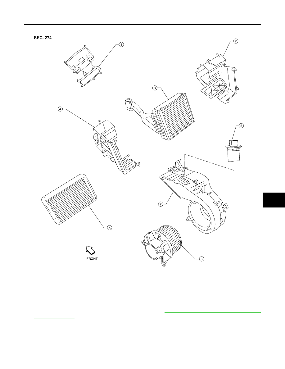
HEATER CORE
ATC-139
C
D
E
F
G
H
I
K
L
M
A
B
ATC
Revision: May 2004
2004 Quest
Rear Heater and Cooling Unit Assembly
Removal and Installation
EJS001OB
FRONT HEATER CORE
1.
Remove the front heater and cooling unit assembly. Refer to
ATC-136, "FRONT HEATER AND COOLING
2.
Remove the blower motor side cover.
3.
Remove the front blower motor.
LJIA0020E
1.
Front cover
2.
Evaporator and heater core case
3.
Evaporator
4.
Side cover
5.
Heater core
6.
Rear blower motor
7.
Blower motor case
8.
Rear blower motor resistor
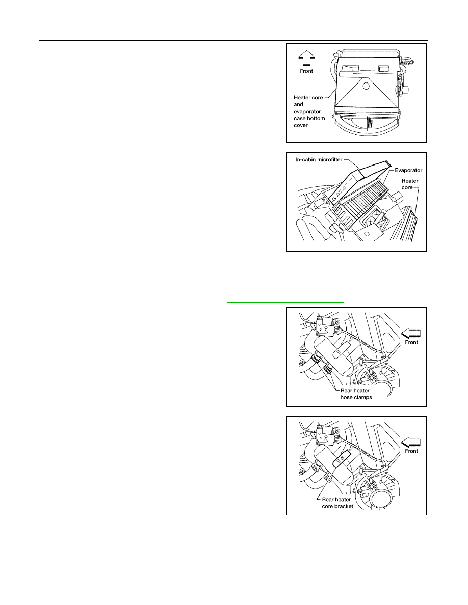
ATC-140
HEATER CORE
Revision: May 2004
2004 Quest
4.
Remove heater core and evaporator case bottom cover.
5.
Remove the blower motor case.
6.
Remove the front heater core.
NOTE:
If the in-cabin microfilters are contaminated from coolant leaking
from the heater core, replace the in-cabin microfilters with new
ones before installing the new front heater core.
7.
Installation is in the reverse order of removal.
REAR HEATER CORE
1.
Partially drain the engine cooling system. Refer to
MA-14, "DRAINING ENGINE COOLANT"
2.
Remove the rear RH interior trim panel. Refer to
EI-30, "Removal and Installation"
.
3.
Disconnect the rear heater core hoses from the rear heater core.
4.
Remove the rear heater core bracket.
5.
Remove the rear heater core.
6.
Installation is in the reverse order of removal.
LJIA0018E
LJIA0019E
LJIA0069E
LJIA0071E
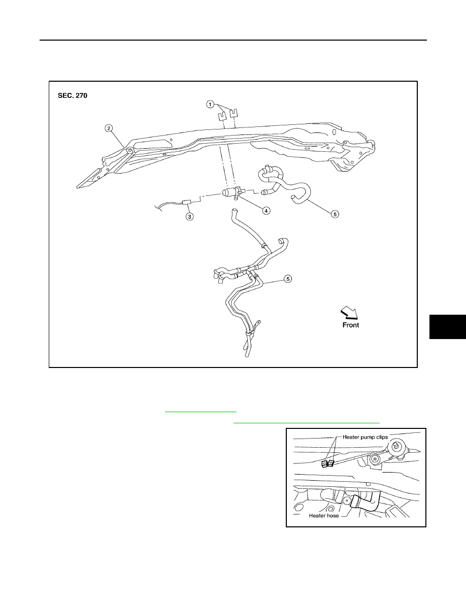
HEATER PUMP
ATC-141
C
D
E
F
G
H
I
K
L
M
A
B
ATC
Revision: May 2004
2004 Quest
HEATER PUMP
PFP:92264
Removal and Installation
EJS001QY
Heater Pump
REMOVAL
1.
Remove the cowl top. Refer to
2.
Partially drain the engine cooling system. Refer to
MA-14, "DRAINING ENGINE COOLANT"
.
3.
Remove the two heater pump clips securing the heater pump to
the cowl top extension.
4.
Disconnect the heater pump electrical connector and the two
heater hoses, then remove the heater pump.
CAUTION:
Do not disassemble the heater pump, replace the heater
pump as an assembly.
INSTALLATION
Installation is in the reverse order of removal.
CAUTION:
Do not disassemble the heater pump, replace the heater pump as an assembly.
LJIA0035E
1.
Heater pump clips
2.
Cowl top extension
3.
Heater pump electrical connector
4.
Heater pump
5.
Heater hoses
LJIA0036E
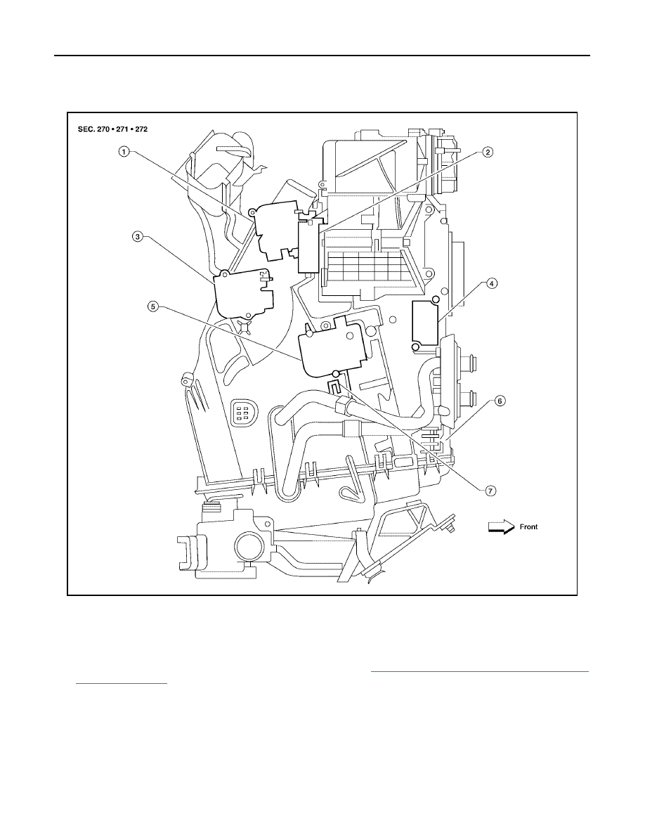
ATC-142
DEFROSTER DOOR MOTOR
Revision: May 2004
2004 Quest
DEFROSTER DOOR MOTOR
PFP:27733
Removal and Installation
EJS001R1
Defroster Door Motor - Front Heater and Cooling Unit Assembly
REMOVAL
1.
Remove the front heater and cooling unit assembly. Refer to
ATC-136, "FRONT HEATER AND COOLING
2.
Remove the steering member from the front heater and cooling unit assembly.
3.
Disconnect the defroster door motor electrical connector.
4.
Remove the two screws and remove the defroster door motor.
INSTALLATION
Installation is in the reverse order of removal.
WJIA0514E
1.
Defroster door motor
2.
Intake door motor (passenger)
3.
Mode door motor
4.
Variable blower control
5.
Air mix door motor (passenger)
6.
Front heater and cooling unit assembly
7.
Intake sensor
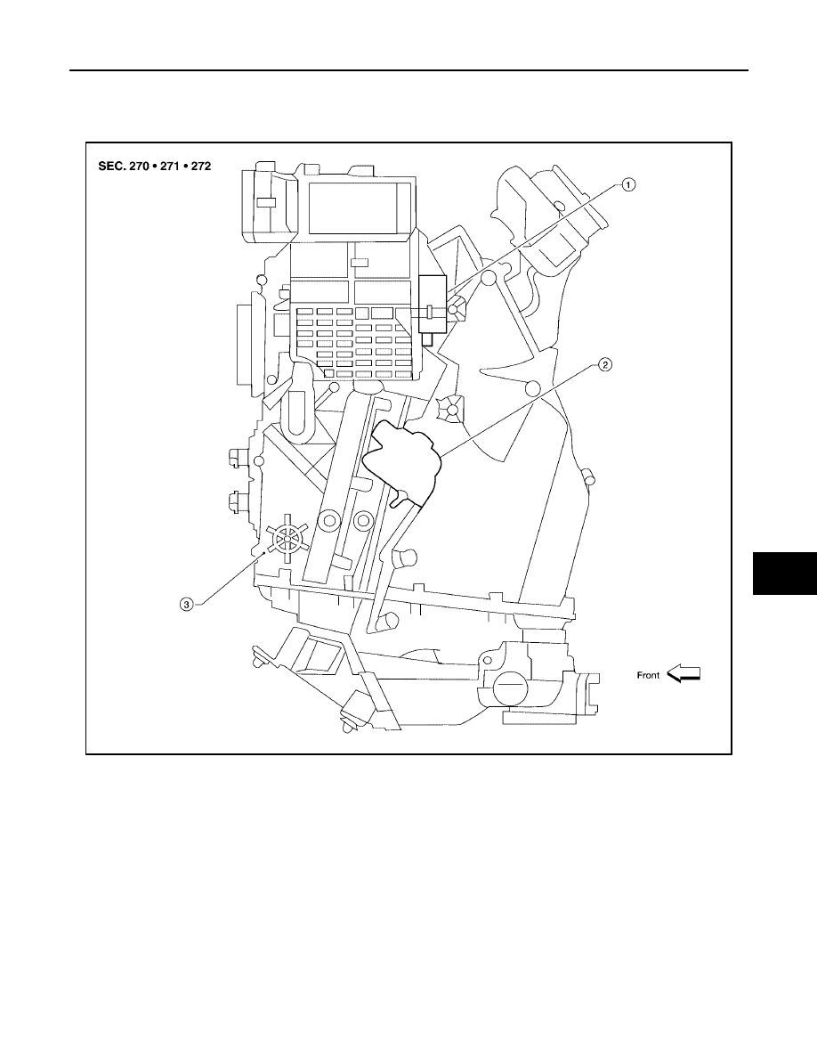
INTAKE DOOR MOTOR
ATC-143
C
D
E
F
G
H
I
K
L
M
A
B
ATC
Revision: May 2004
2004 Quest
INTAKE DOOR MOTOR
PFP:27730
Components
EJS001UA
Intake Door Motor (Driver) - Front Heater and Cooling Unit Assembly
WJIA0446E
1.
Intake door motor
2.
Air mix door motor (driver)
3.
Front heater and cooling unit
assembly
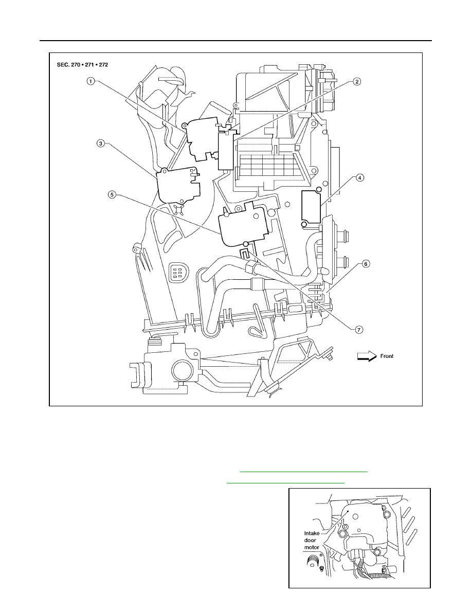
ATC-144
INTAKE DOOR MOTOR
Revision: May 2004
2004 Quest
Intake Door Motor (Passenger) - Front Heater and Cooling Unit Assembly
Removal and Installation
EJS001O8
DRIVER SIDE
1.
Remove the lower driver instrument panel. Refer to
IP-12, "Instrument Lower Panel LH"
2.
Remove the center console trim panel. Refer to
IP-10, "Removal and Installation"
3.
Disconnect the intake door motor electrical connector.
4.
Remove the three screws and remove the intake door motor.
5.
Installation is in the reverse order of removal.
WJIA0514E
1.
Defroster door motor
2.
Intake door motor (passenger)
3.
Mode door motor
4.
Variable blower control
5.
Air mix door motor (passenger)
6.
Front heater and cooling unit assembly
7.
Intake sensor
LJIA0082E

INTAKE DOOR MOTOR
ATC-145
C
D
E
F
G
H
I
K
L
M
A
B
ATC
Revision: May 2004
2004 Quest
PASSENGER SIDE
1.
Remove the front heater and cooling unit assembly. Refer to
ATC-136, "FRONT HEATER AND COOLING
2.
Remove the steering member from the front heater and cooling unit assembly.
3.
Disconnect the intake door motor electrical connector.
4.
Remove the three screws and remove the intake door motor.
5.
Installation is in the reverse order of removal.
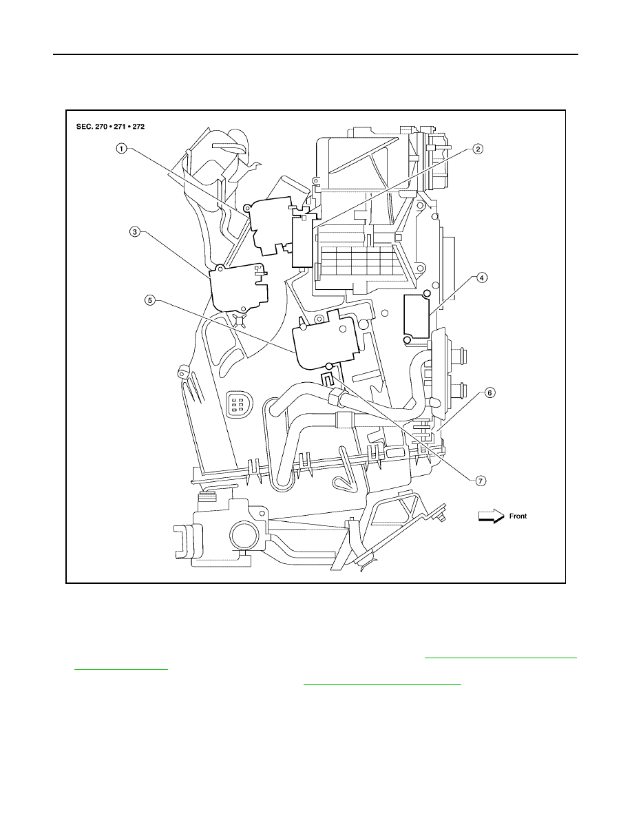
ATC-146
MODE DOOR MOTOR
Revision: May 2004
2004 Quest
MODE DOOR MOTOR
PFP:27731
Removal and Installation
EJS001OC
Mode Door Motor - Front Heater and Cooling Unit Assembly
REMOVAL
1.
Remove the instrument passenger lower panel and glove box. Refer to
IP-13, "Instrument Lower Panel
.
2.
Remove the center console trim panel. Refer to
IP-10, "Removal and Installation"
WJIA0514E
1.
Defroster door motor
2.
Intake door motor (passenger)
3.
Mode door motor
4.
Variable blower control
5.
Air mix door motor (passenger)
6.
Front heater and cooling unit assembly
7.
Intake sensor
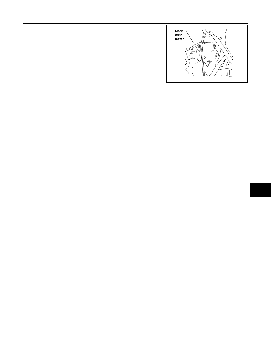
MODE DOOR MOTOR
ATC-147
C
D
E
F
G
H
I
K
L
M
A
B
ATC
Revision: May 2004
2004 Quest
3.
Disconnect the mode door motor electrical connector.
4.
Remove the three screws and remove the mode door motor.
INSTALLATION
Installation is in the reverse order of removal.
LJIA0083E
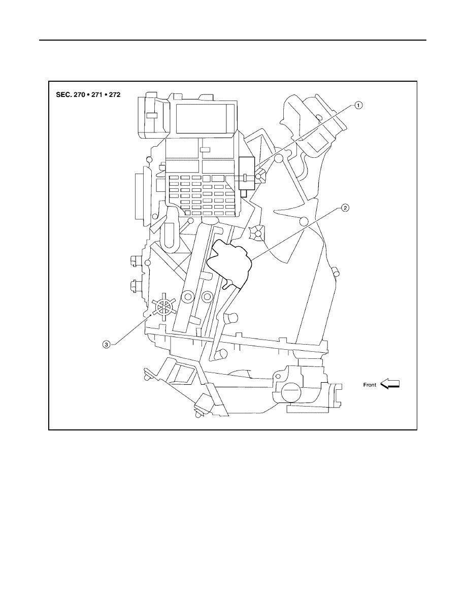
ATC-148
AIR MIX DOOR MOTOR
Revision: May 2004
2004 Quest
AIR MIX DOOR MOTOR
PFP:27732
Components
EJS001UB
Air Mix Door Motor (Driver) - Front Heater and Cooling Unit Assembly
WJIA0446E
1.
Intake door motor (driver)
2.
Air mix door motor (driver)
3.
Front heater and cooling unit assembly
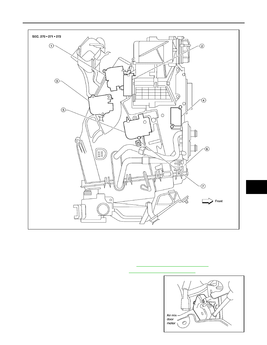
AIR MIX DOOR MOTOR
ATC-149
C
D
E
F
G
H
I
K
L
M
A
B
ATC
Revision: May 2004
2004 Quest
Air Mix Door Motor (Passenger) - Front Heater and Cooling Unit Assembly
Removal and Installation
EJS001OD
FRONT AIR MIX DOOR MOTOR (DRIVER)
1.
Remove the lower driver instrument panel. Refer to
IP-12, "Instrument Lower Panel LH"
2.
Remove the center console trim panel. Refer to
IP-10, "Removal and Installation"
.
3.
Disconnect the air mix door motor electrical connector.
4.
Remove the three screws and remove the air mix door motor.
5.
Installation is in the reverse order of removal.
WJIA0514E
1.
Defroster door motor
2.
Intake door motor (passenger)
3.
Mode door motor
4.
Variable blower control
5.
Air mix door motor (passenger)
6.
Front heater and cooling unit assembly
7.
Intake sensor
LJIA0084E
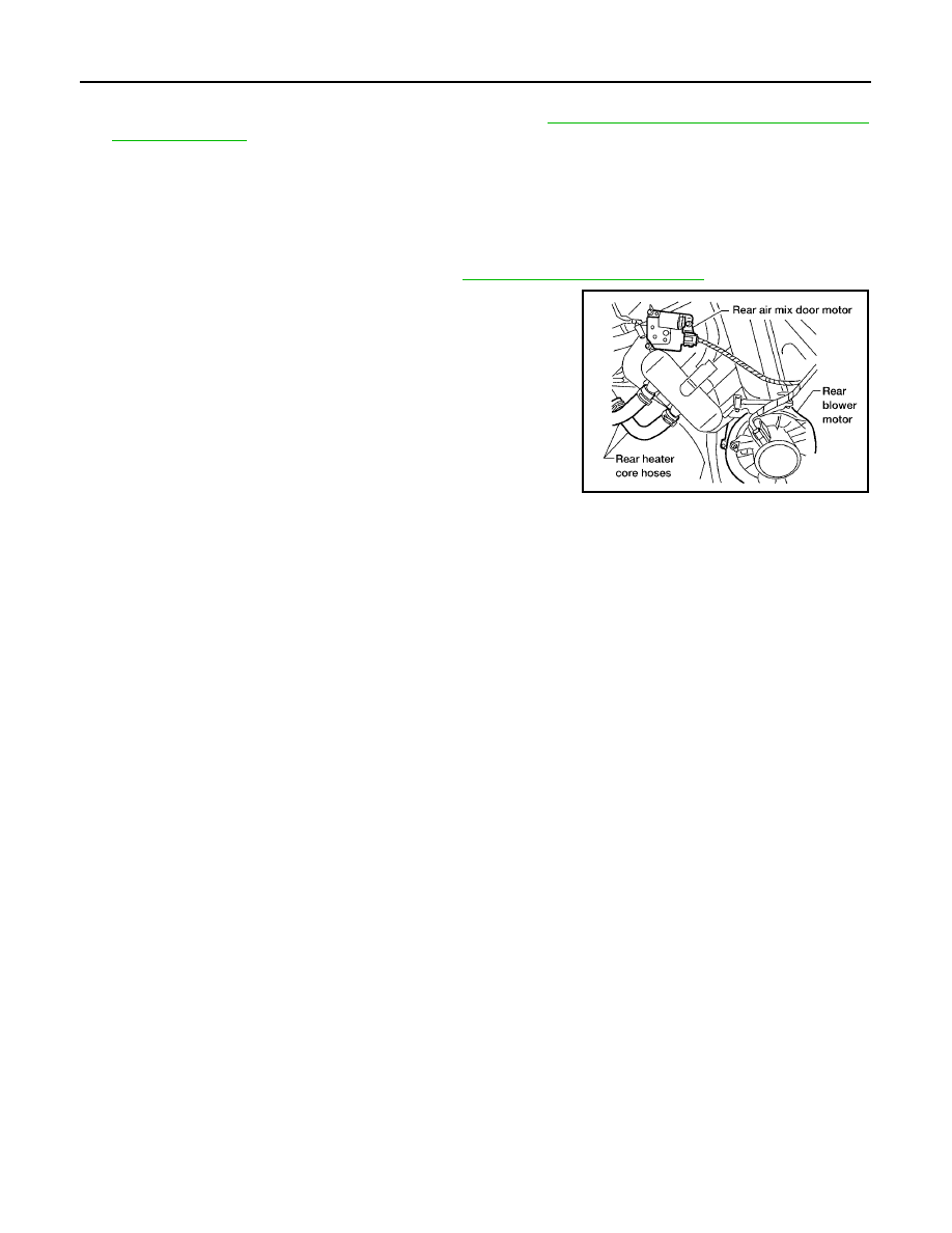
ATC-150
AIR MIX DOOR MOTOR
Revision: May 2004
2004 Quest
FRONT AIR MIX DOOR MOTOR (PASSENGER)
1.
Remove the front heater and cooling unit assembly. Refer to
ATC-136, "FRONT HEATER AND COOLING
2.
Remove the steering member from the front heater and cooling unit assembly.
3.
Disconnect the air mix door motor electrical connector.
4.
Remove the three screws and remove the air mix door motor.
5.
Installation is in the reverse order of removal.
REAR AIR MIX DOOR MOTOR
1.
Remove the RH rear interior trim panel. Refer to
2.
Disconnect the rear air mix door motor electrical connector.
3.
Remove the three screws and remove the rear air mix door
motor.
4.
Installation is in the reverse order of removal.
LJIA0021E
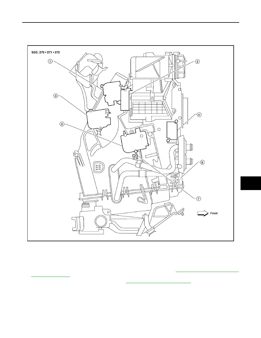
VARIABLE BLOWER CONTROL
ATC-151
C
D
E
F
G
H
I
K
L
M
A
B
ATC
Revision: May 2004
2004 Quest
VARIABLE BLOWER CONTROL
PFP:27200
Removal and Installation
EJS001OE
Variable Blower Control - Front Heater and Cooling Unit Assembly
REMOVAL
1.
Remove the instrument passenger lower panel and glove box. Refer to
IP-13, "Instrument Lower Panel
2.
Remove the center console trim panel. Refer to
IP-10, "Removal and Installation"
.
3.
Disconnect the variable blower control electrical connector.
4.
Remove the two screws and remove the variable blower control.
INSTALLATION
Installation is in the reverse order of removal.
WJIA0514E
1.
Defroster door motor
2.
Intake door motor (passenger)
3.
Mode door motor
4.
Variable blower control
5.
Air mix door motor (passenger)
6.
Front heater and cooling unit assembly
7.
Intake sensor
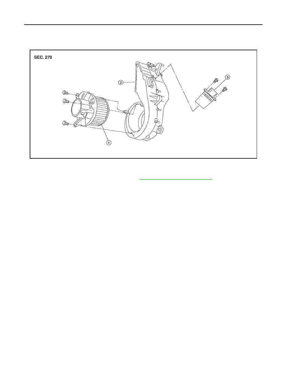
ATC-152
REAR BLOWER MOTOR RESISTOR
Revision: May 2004
2004 Quest
REAR BLOWER MOTOR RESISTOR
PFP:27150
Removal and Installation
EJS001R8
Rear Blower Motor Resistor
REMOVAL
1.
Remove the rear RH interior trim panel. Refer to
2.
Disconnect the rear blower motor resistor electrical connector.
3.
Remove the two screws and remove the rear blower motor resistor.
INSTALLATION
Installation is in the reverse order of removal.
LJIA0055E
1.
Rear blower motor
2.
Rear blower motor case
3.
Rear blower motor resistor
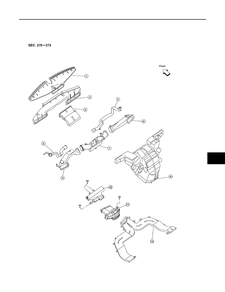
DUCTS AND GRILLES
ATC-153
C
D
E
F
G
H
I
K
L
M
A
B
ATC
Revision: May 2004
2004 Quest
DUCTS AND GRILLES
PFP:27860
Components
EJS001UC
Ducts - Front Heater and Cooling Unit Assembly
LJIA0085E
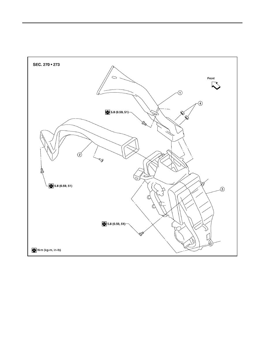
ATC-154
DUCTS AND GRILLES
Revision: May 2004
2004 Quest
Ducts - Rear Heater and Cooling Unit Assembly
1.
Defroster nozzle
2.
Fresh air duct
3.
Defroster duct
4.
RH side demister duct
5.
LH side demister duct
6.
RH ventilator duct
7.
Center ventilator duct
8.
LH ventilator duct
9.
Front heater and cooling unit assembly
10. Floor connector duct
11.
Floor distribution duct
12. Floor duct
LJIA0086E
1.
Rear overhead duct
2.
Rear floor duct
3.
Rear heater and cooling unit assembly
4.
Clips
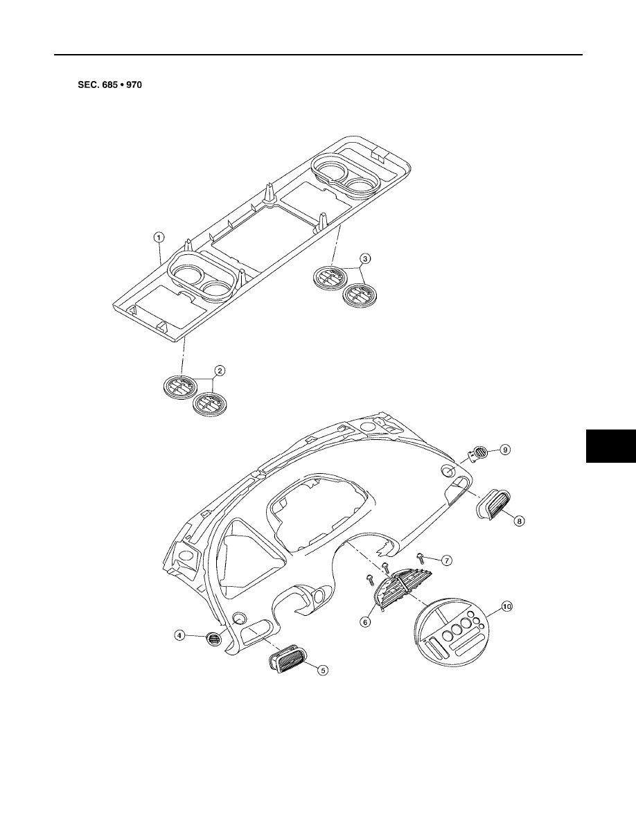
DUCTS AND GRILLES
ATC-155
C
D
E
F
G
H
I
K
L
M
A
B
ATC
Revision: May 2004
2004 Quest
Grilles
LJIA0087E
1.
Overhead console
2.
Overhead console front grilles
3.
Overhead console rear grilles
4.
LH side demister grille
5.
LH ventilator grille
6.
Center ventilator grille

ATC-156
DUCTS AND GRILLES
Revision: May 2004
2004 Quest
Removal and Installation
EJS001OF
DEFROSTER NOZZLE
1.
Remove the front heater and cooling unit assembly. Refer to
ATC-136, "FRONT HEATER AND COOLING
2.
Remove the defroster nozzle.
3.
Installation is in the reverse order of removal.
FRESH AIR DUCT
1.
Remove the front heater and cooling unit assembly. Refer to
ATC-136, "FRONT HEATER AND COOLING
2.
Remove the defroster nozzle.
3.
Remove the fresh air duct.
4.
Installation is in the reverse order of removal.
DEFROSTER DUCT
1.
Remove the instrument panel trim. Refer to
IP-10, "Removal and Installation"
2.
Remove the defroster duct.
3.
Installation is in the reverse order of removal.
RH AND LH SIDE DEMISTER DUCT
1.
Remove the instrument panel trim. Refer to
IP-10, "Removal and Installation"
2.
Remove the RH or LH side demister duct.
3.
Installation is in the reverse order of removal.
RH, LH, AND CENTER VENTILATOR DUCT
1.
Remove the instrument panel trim. Refer to
IP-10, "Removal and Installation"
2.
Remove the RH, center, and LH ventilator duct.
3.
Installation is in the reverse order of removal.
FLOOR CONNECTOR DUCT
1.
Remove the front heater and cooling unit assembly. Refer to
ATC-136, "FRONT HEATER AND COOLING
2.
Remove the three clips and remove the floor connector duct.
3.
Installation is in the reverse order of removal.
FLOOR DISTRIBUTION DUCT
1.
Remove the center console lower cover. Refer to
IP-10, "Removal and Installation"
2.
Remove the clip and remove the floor distribution duct.
3.
Installation is in the reverse order of removal.
FLOOR DUCT
1.
Remove the floor carpet. Refer to
2.
Remove the floor duct.
3.
Installation is in the reverse order of removal.
REAR OVERHEAD DUCT
1.
Remove the rear RH interior trim panel. Refer to
EI-30, "Removal and Installation"
.
2.
Remove the headliner. Refer to
EI-23, "Removal and Installation"
.
NOTE:
The rear headliner duct connected to the rear overhead duct is part of the headlining trim panel and is
replaced as an assembly. Refer to
3.
Remove the bolt and two clips, and remove the rear overhead duct.
4.
Installation is in the reverse order of removal.
7.
Center ventilator grille screws
8.
RH ventilator grille
9.
RH side demister grille
10. Cluster lid C

DUCTS AND GRILLES
ATC-157
C
D
E
F
G
H
I
K
L
M
A
B
ATC
Revision: May 2004
2004 Quest
REAR FLOOR DUCT
1.
Remove the rear RH interior trim panel. Refer to
EI-30, "Removal and Installation"
2.
Reposition the floor carpet out of the way.
3.
Remove the screw and clip, then remove the rear floor duct.
4.
Installation is in the reverse order of removal.
GRILLES
1.
Remove the interior trim panel as necessary that contains the grille to be removed. Refer to
.
2.
Remove the grille from the interior trim panel.
3.
Installation is in the reverse order of removal.
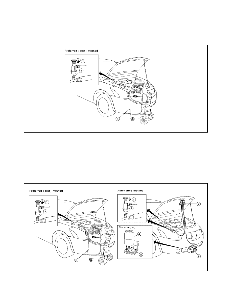
ATC-158
REFRIGERANT LINES
Revision: May 2004
2004 Quest
REFRIGERANT LINES
PFP:92600
HFC-134a (R-134a) Service Procedure
EJS001OG
SETTING OF SERVICE TOOLS AND EQUIPMENT
Discharging Refrigerant
WARNING:
Avoid breathing A/C refrigerant and lubricant vapor or mist. Exposure may irritate eyes, nose and
throat. Remove HFC-134a (R-134a) refrigerant from the A/C system using certified service equipment
meeting requirements of SAE J2210 HFC-134a (R-134a) recycling equipment or SAE J2201 HFC-134a
(R-134a) recovery equipment. If an accidental system discharge occurs, ventilate the work area before
resuming service. Additional health and safety information may be obtained from the refrigerant and
lubricant manufacturers.
Evacuating System and Charging Refrigerant
1.
Shut-off valve
2.
A/C service valve
3.
Recovery/Recycling equipment ACR 2000
(J-43600) with refrigerant identifier
WJIA0374E
1.
Shut-off valve
2.
A/C service valve
3.
Recovery/Recycling equipment ACR
2000 (J-43600) with refrigerant identifier
WJIA0375E
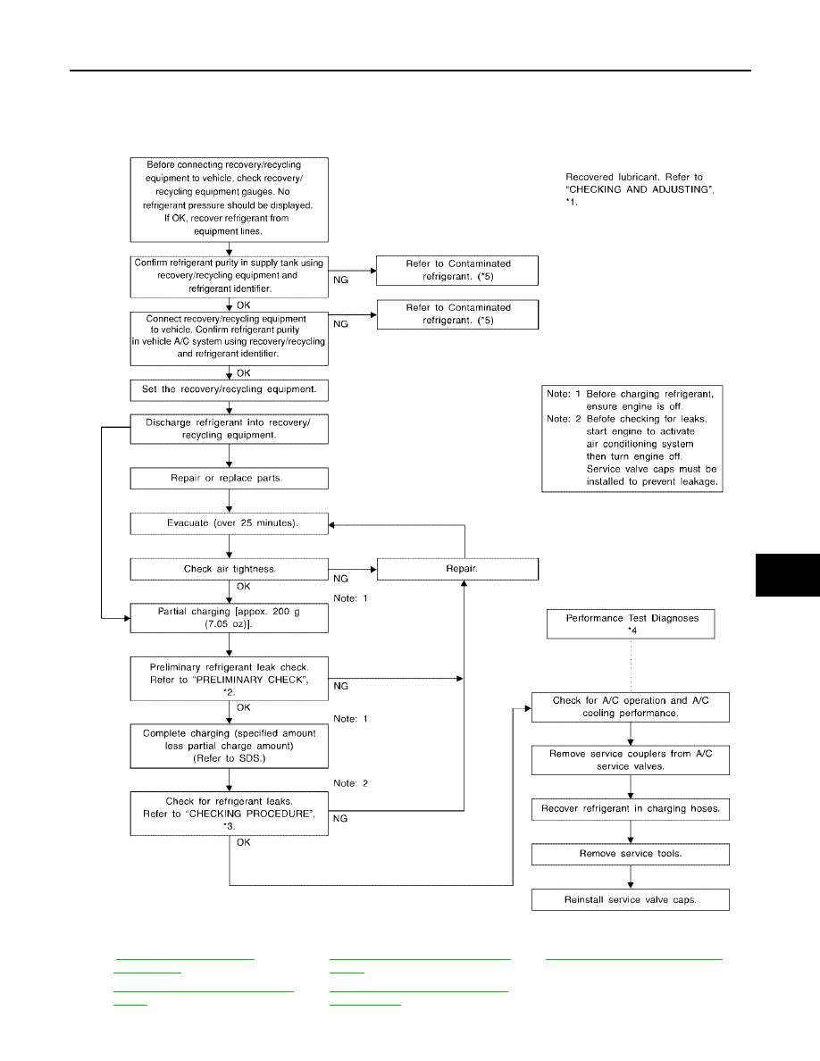
REFRIGERANT LINES
ATC-159
C
D
E
F
G
H
I
K
L
M
A
B
ATC
Revision: May 2004
2004 Quest
4.
Refrigerant container (HFC-134a)
5.
Weight scale (J-39650)
6.
Evacuating vacuum pump (J-39699)
7.
Manifold gauge set (J-39183)
*1
.
*3
ATC-172, "Checking for Refrigerant
Leaks"
*5
ATC-5, "Contaminated Refrigerant"
*2
ATC-172, "Checking for Refrigerant
Leaks"
.
*4
ATC-106, "PERFORMANCE TEST
DIAGNOSES"
.
WJIA0530E
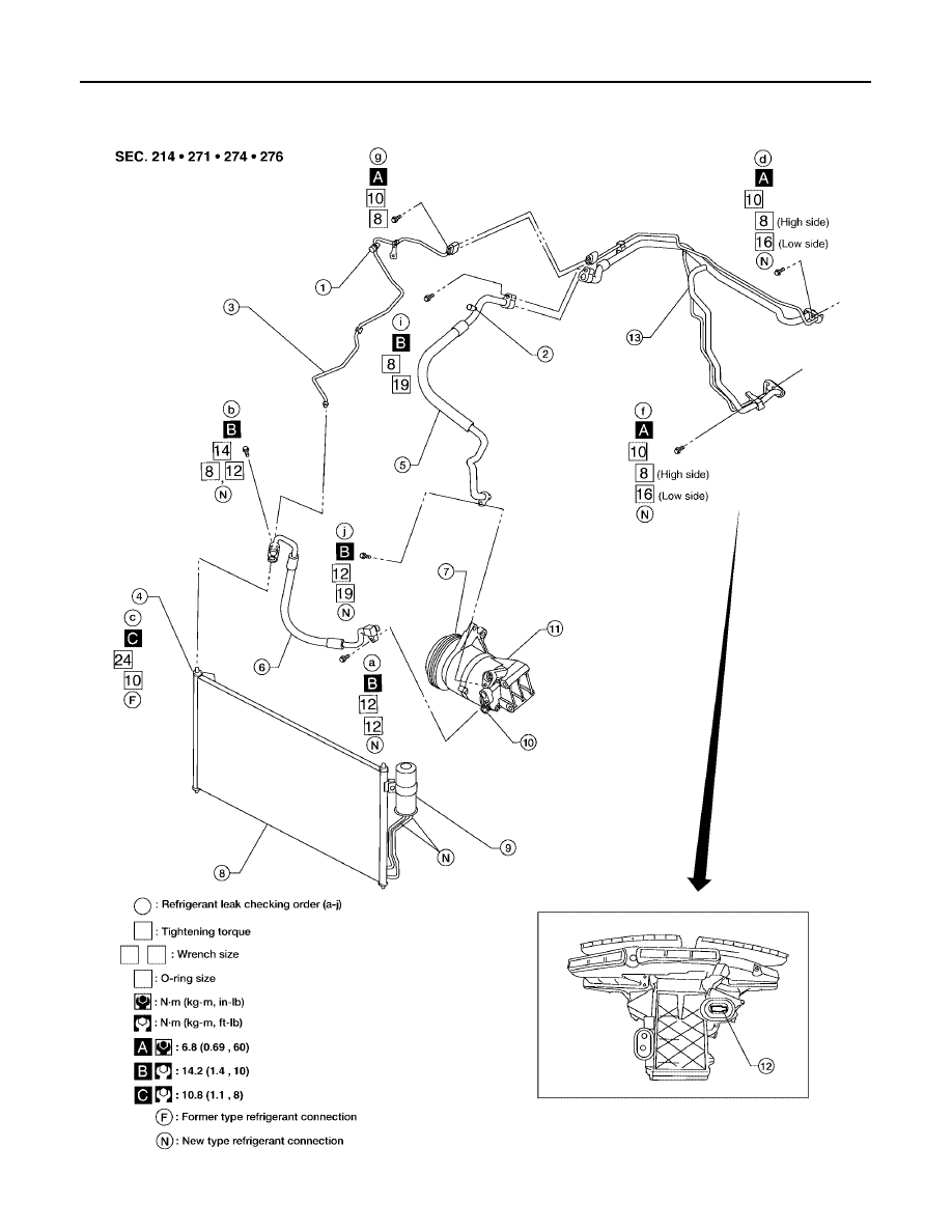
ATC-160
REFRIGERANT LINES
Revision: May 2004
2004 Quest
Components
EJS001OH
Front A/C Compressor and Condenser
WJIA0370E
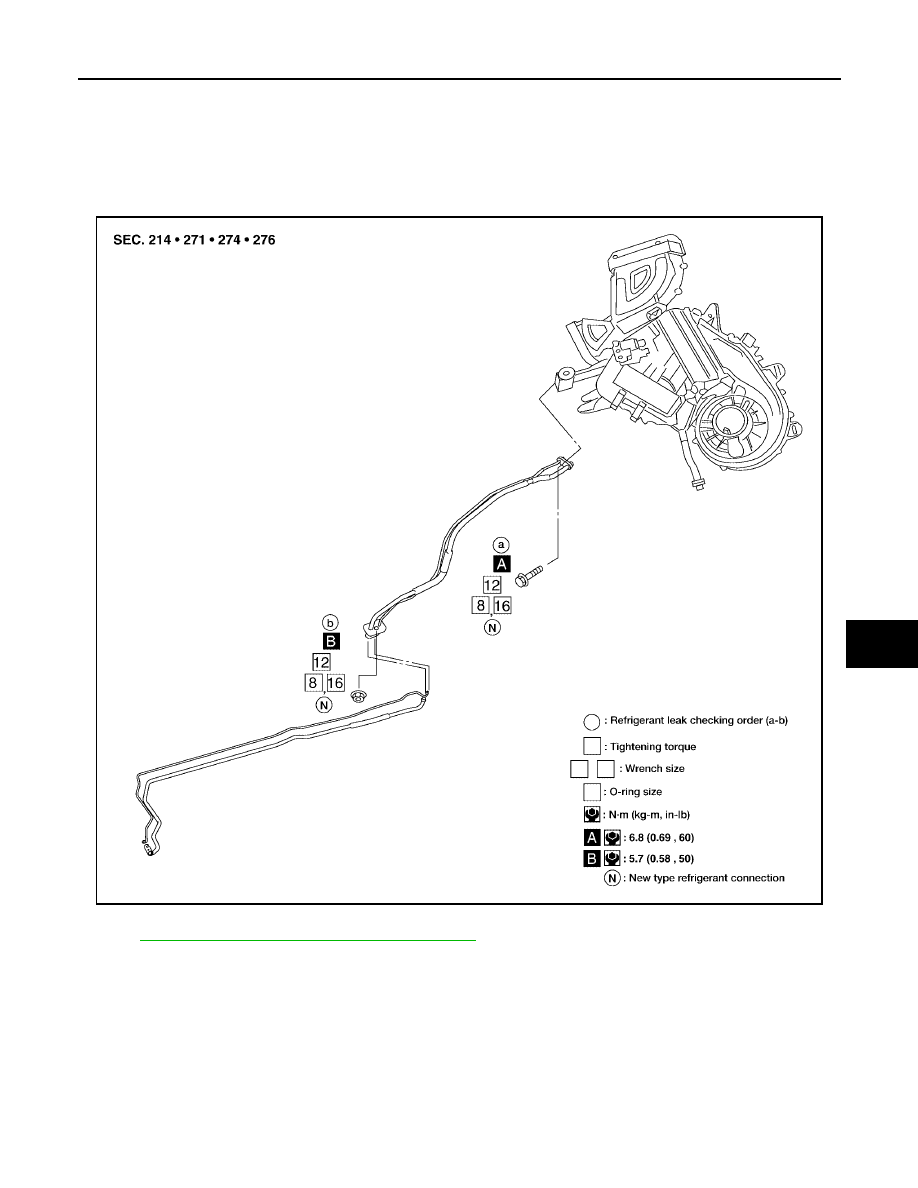
REFRIGERANT LINES
ATC-161
C
D
E
F
G
H
I
K
L
M
A
B
ATC
Revision: May 2004
2004 Quest
Rear A/C
NOTE:
Refer to
ATC-7, "Precautions for Refrigerant Connection"
1.
High-pressure service valve
2.
Low-pressure service valve
3.
High-pressure pipe
4.
Refrigerant pressure sensor
5.
Low-pressure flexible hose
6.
High-pressure flexible hose
7.
Shaft seal
8.
Condenser
9.
Liquid tank
10. Pressure relief valve
11.
Compressor
12. Expansion valve (front)
13. High/low pressure pipe
LJIA0016E
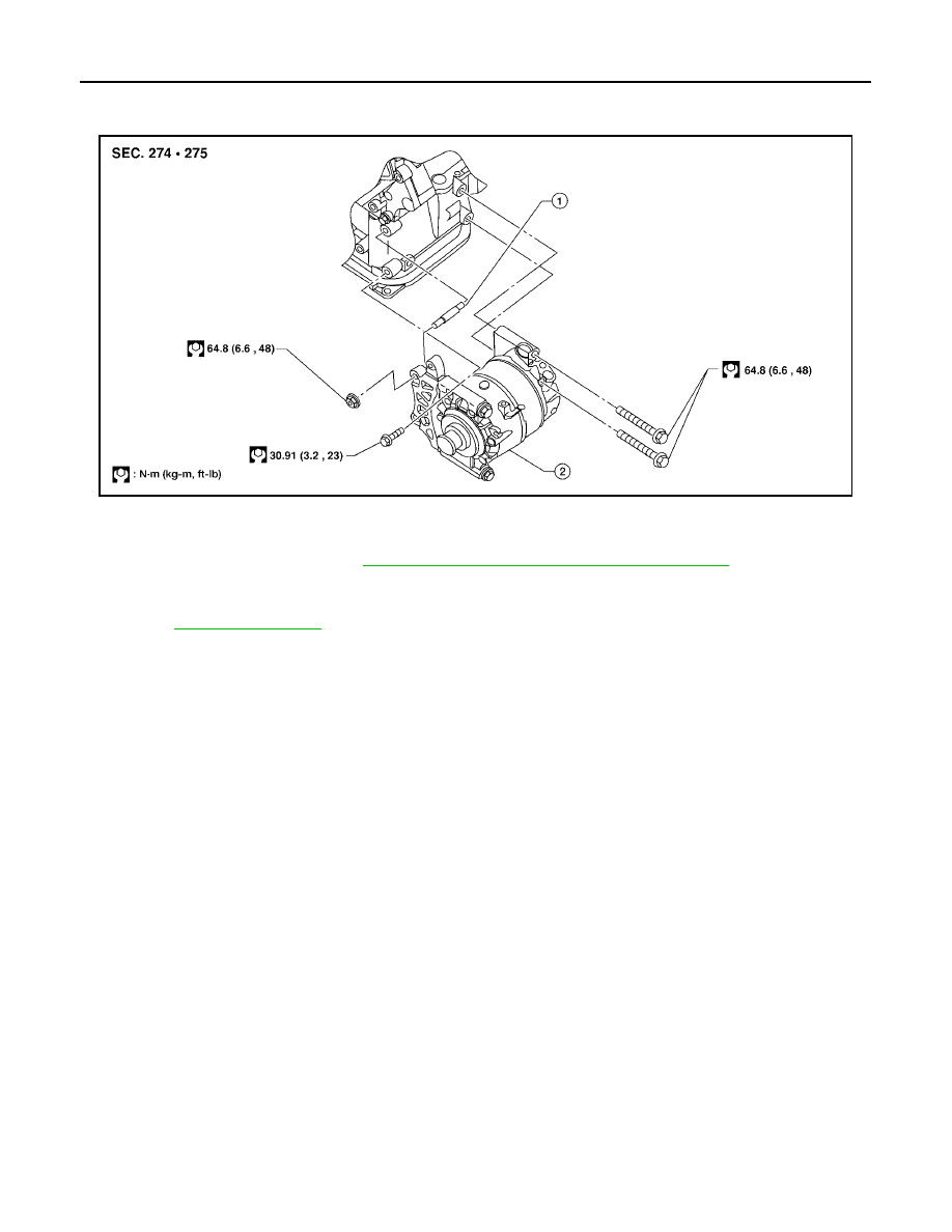
ATC-162
REFRIGERANT LINES
Revision: May 2004
2004 Quest
Removal and Installation for Compressor
EJS001OI
Compressor Mounting
REMOVAL
1.
Discharge the refrigerant. Refer to
ATC-158, "HFC-134a (R-134a) Service Procedure"
2.
Remove the engine under cover and the splash shield.
3.
Remove the drive belt.
Refer to
4.
Remove the compressor mounting stud.
5.
Disconnect the compressor connector.
6.
Disconnect the high-pressure flexible hose and low-pressure flexible hose from the compressor.
CAUTION:
Cap or wrap the joint of the pipe with suitable material such as vinyl tape to avoid the entry of air.
7.
Remove the compressor bolts and nut using power tools.
INSTALLATION
Installation is in the reverse order of removal.
CAUTION:
●
Replace the O-ring of the low-pressure flexible hose and high-pressure flexible hose with a new
one, then apply compressor oil to it when installing it.
●
After charging refrigerant, check for leaks.
WJIA0371E
1.
Stud
2.
Compressor
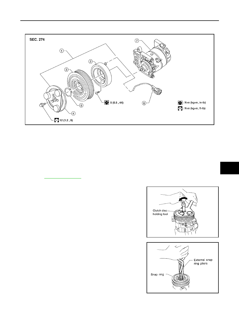
REFRIGERANT LINES
ATC-163
C
D
E
F
G
H
I
K
L
M
A
B
ATC
Revision: May 2004
2004 Quest
Removal and Installation for Compressor Clutch
EJS001OJ
Magnet Clutch Assembly
REMOVAL
NOTE:
For clarity, the compressor is shown out of the vehicle, but the compressor does not need to be removed to
remove the compressor clutch.
1.
Remove the engine under cover and the splash shield.
2.
Remove the drive belt.
Refer to
3.
Disconnect the compressor electrical connector.
4.
Remove the center bolt while holding the clutch disc stationary
using Tool as shown.
5.
Remove the clutch disc.
6.
Remove the snap ring using external snap ring pliers or suitable
tool.
WJIA0372E
1.
Magnet clutch assembly
2.
Magnet coil
3.
Pulley
4.
Clutch disc
5.
Snap ring
6.
Thermal protector (built in)
7.
Compressor
Tool number
: J-44614 (
—
)
WHA228
RHA072C
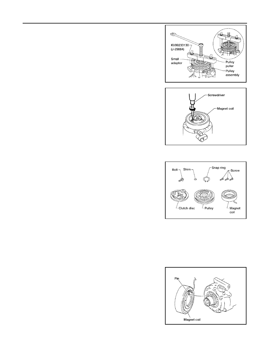
ATC-164
REFRIGERANT LINES
Revision: May 2004
2004 Quest
7.
Remove the pulley using Tool with a small adapter. Position the
small adapter on the end of the drive shaft and the center of the
puller on the small adapter.
CAUTION:
To prevent deformation of the pulley groove, the puller
claws should be hooked under the pulley groove and not
into the pulley groove.
8.
Remove the magnet coil harness clip using a screwdriver,
remove the three magnet coil fixing screws and remove the
magnet coil.
INSPECTION
Clutch Disc
If the contact surface shows signs of damage due to excessive heat,
replace clutch disc and pulley.
Pulley
Check the appearance of the pulley assembly. If contact surface of pulley shows signs of excessive grooving,
replace clutch disc and pulley. The contact surfaces of the pulley assembly should be cleaned with a suitable
solvent before reinstallation.
Coil
Check magnet coil for loose connections or any cracked insulation.
INSTALLATION
1.
Install the magnet coil.
CAUTION:
Be sure to align the magnet coil pin with the hole in the
compressor front head.
2.
Install the magnet coil harness clip using a screwdriver.
LHA173
WHA212
WHA183
WHA213
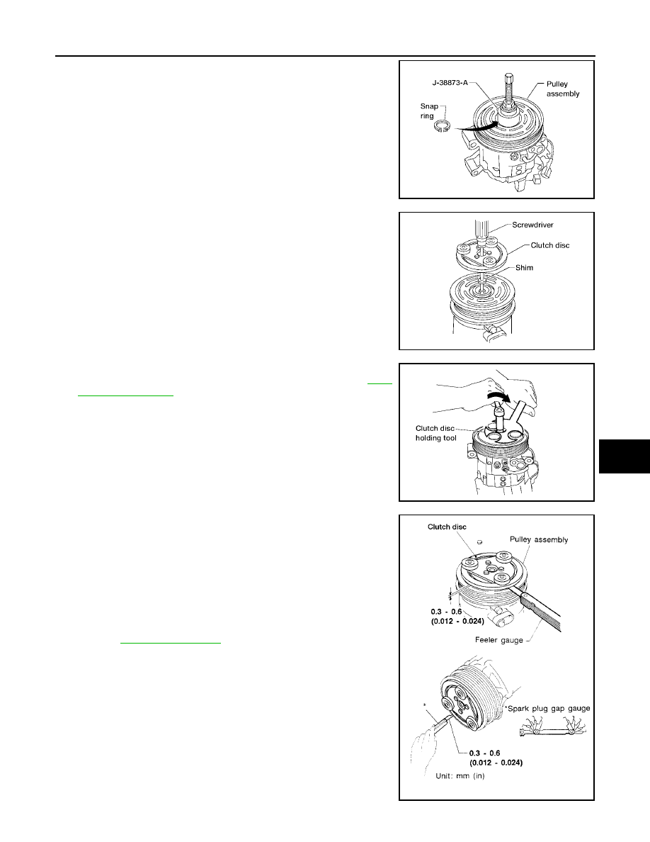
REFRIGERANT LINES
ATC-165
C
D
E
F
G
H
I
K
L
M
A
B
ATC
Revision: May 2004
2004 Quest
3.
Install the pulley assembly using Tool and a wrench, then install
the snap ring using snap ring pliers.
4.
Install the clutch disc on the compressor shaft, together with the
original shim(s). Press the clutch disc down by hand.
5.
Install the clutch pulley bolt using Tool, to prevent the clutch disc
from turning and tighten the bolt to specification. Refer to
CAUTION:
After tightening the clutch pulley bolt, check that the clutch
pulley rotates smoothly.
6.
Check the pulley clearance all the way around the clutch disc as
shown.
7.
If the specified clearance is not obtained, replace the adjusting
spacer to readjust.
8.
Connect the compressor electrical connector.
9.
Install the drive belt.
Refer to
10. Install the engine under cover and the splash shield.
WJIA0368E
WHA184
Tool number
: J-44614 (
—
)
WHA229
Clutch disc-to-pulley clearance
: 0.3 - 0.6 mm
(0.012 - 0.024 in)
WHA194

ATC-166
REFRIGERANT LINES
Revision: May 2004
2004 Quest
BREAK-IN OPERATION
When replacing compressor clutch assembly, always conduct the break-in operation. This is done by engag-
ing and disengaging the clutch about 30 times. Break-in operation raises the level of transmitted torque.
Removal and Installation for Low-pressure Flexible Hose
EJS001OK
REMOVAL
1.
Remove the engine under cover.
2.
Discharge the refrigerant. Refer to
ATC-158, "HFC-134a (R-134a) Service Procedure"
CAUTION:
Cap or wrap the joint of the pipe with suitable material such as vinyl tape to avoid the entry of air.
3.
Remove the low-pressure flexible hose. Refer to
INSTALLATION
Installation is in the reverse order of removal.
Refer to
CAUTION:
●
Replace the O-ring of the low-pressure flexible hose with a new one, then apply compressor oil to
it when installing it.
●
After charging refrigerant, check for leaks.
Removal and Installation for High-pressure Flexible Hose
EJS001OL
REMOVAL
1.
Remove the engine under cover.
2.
Discharge the refrigerant. Refer to
ATC-158, "HFC-134a (R-134a) Service Procedure"
3.
Remove the high-pressure flexible hose. Refer to
CAUTION:
Cap or wrap the joint of the pipe with suitable material such as vinyl tape to avoid the entry of air.
INSTALLATION
Installation is in the reverse order of removal.
Refer to
CAUTION:
●
Replace the O-ring of the high-pressure flexible hose with a new one, then apply compressor oil to
it when installing it.
●
After charging refrigerant, check for leaks.
Removal and Installation for High-pressure Pipe
EJS001OM
REMOVAL
1.
Reposition the IPDM E/R aside.
2.
Remove the windshield washer fluid bottle filler neck.
3.
Reposition the coolant reservoir tank aside.
4.
Reposition the power steering fluid reservoir aside.
5.
Discharge the refrigerant. Refer to
ATC-158, "HFC-134a (R-134a) Service Procedure"
6.
Remove the high-pressure pipe. Refer to
CAUTION:
Cap or wrap the joint of the pipe with suitable material such as vinyl tape to avoid the entry of air.
INSTALLATION
Installation is in the reverse order of removal.
Refer to
CAUTION:
●
Replace the O-ring of the high-pressure pipe with a new one, then apply compressor oil to it when
installing it.
●
After charging refrigerant, check for leaks.
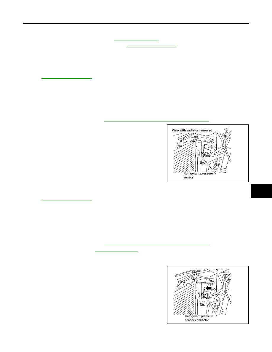
REFRIGERANT LINES
ATC-167
C
D
E
F
G
H
I
K
L
M
A
B
ATC
Revision: May 2004
2004 Quest
Removal and Installation for High/Low-pressure Pipe
EJS001QV
REMOVAL
1.
Remove the engine assembly. Refer to
2.
Remove the high/low-pressure pipe. Refer to
.
CAUTION:
Cap or wrap the joint of the pipes with suitable material such as vinyl tape to avoid the entry of air.
INSTALLATION
Installation is in the reverse order of removal.
Refer to
CAUTION:
●
Replace the O-ring of the high/low-pressure pipe with a new one, then apply compressor oil to it
when installing it.
●
After charging refrigerant, check for leaks.
Removal and Installation for Refrigerant Pressure Sensor
EJS001ON
REMOVAL
1.
Discharge the refrigerant. Refer to
ATC-158, "HFC-134a (R-134a) Service Procedure"
.
2.
Disconnect the refrigerant pressure sensor connector and
remove the refrigerant pressure sensor from condenser.
CAUTION:
Be careful not to damage the condenser fins.
INSTALLATION
Installation is in the reverse order of removal.
Refer to
CAUTION:
●
Be careful not to damage the condenser fins.
●
Apply compressor oil to the O-ring of the refrigerant pressure sensor when installing it.
●
After charging refrigerant, check for leaks.
Removal and Installation for Condenser
EJS001OO
REMOVAL
1.
Discharge the refrigerant. Refer to
ATC-158, "HFC-134a (R-134a) Service Procedure"
.
2.
CAUTION:
Be careful not to damage the core surface of the condenser and the radiator.
3.
Disconnect the high-pressure flexible hose and the high-pres-
sure pipe from the condenser.
CAUTION:
Cap or wrap the joint of the pipe with suitable material such
as vinyl tape to avoid the entry of air.
4.
Disconnect the refrigerant pressure sensor connector.
5.
Remove the refrigerant pressure sensor.
WJIA0123E
WJIA0124E
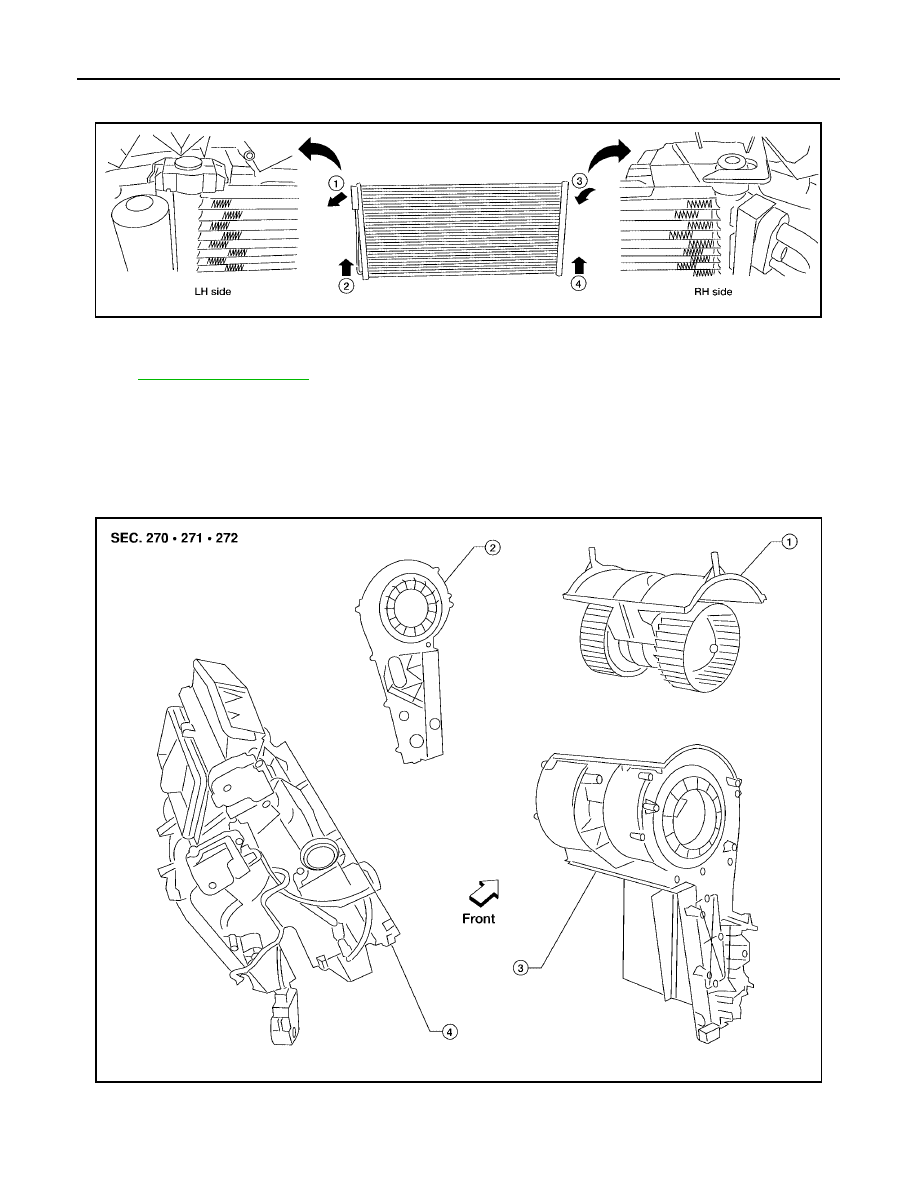
ATC-168
REFRIGERANT LINES
Revision: May 2004
2004 Quest
6.
Carefully release retaining clips located on top driver side of condenser and rotate the condenser out of its
mounts as shown.
INSTALLATION
Installation is in the reverse order of removal.
Refer to
CAUTION:
●
Replace the O-rings of the high-pressure pipe and the high-pressure flexible hose with new ones,
then apply compressor oil to them after installing them.
●
After charging refrigerant, check for leaks.
Removal and Installation for Front Evaporator
EJS001OP
Front Heater and Cooling Unit Assembly
WJIA0373E
LJIA0017E
1.
Front blower motor
2.
Blower motor side cover
3.
Blower motor case
4.
Heater core and evaporator case
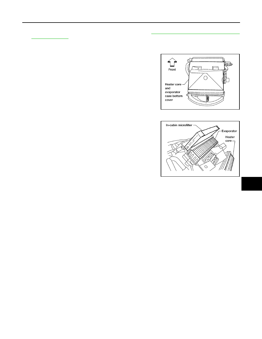
REFRIGERANT LINES
ATC-169
C
D
E
F
G
H
I
K
L
M
A
B
ATC
Revision: May 2004
2004 Quest
REMOVAL
1.
Remove the front heater and cooling unit assembly. Refer to
ATC-136, "FRONT HEATER AND COOLING
2.
Remove the blower motor side cover.
3.
Remove the front blower motor.
4.
Remove the heater core and evaporator case bottom cover.
5.
Remove the blower motor case.
6.
Remove the two in-cabin microfilters.
7.
Remove the evaporator.
INSTALLATION
Installation is in the reverse order of removal.
CAUTION:
●
Replace the O-rings on the low-pressure flexible hose and the high-pressure pipe with new ones.
Apply compressor oil to the O-rings before installing them.
●
When installing the in-cabin microfilters, face the microfilters according to the air flow direction
arrow printed on the side of the filters.
LJIA0018E
LJIA0019E
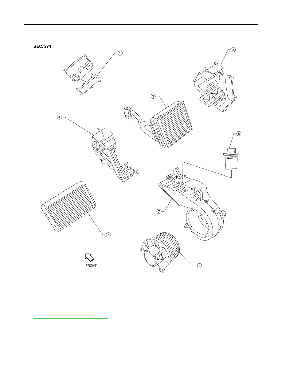
ATC-170
REFRIGERANT LINES
Revision: May 2004
2004 Quest
Removal and Installation for Rear Evaporator
EJS001OW
Rear Heater and Cooling Unit Assembly
REMOVAL
1.
Remove the rear heater and cooling unit assembly from the vehicle. Refer to
2.
Remove the rear blower motor.
3.
Remove the rear blower motor resistor.
LJIA0020E
1.
Front cover
2.
Evaporator and heater core case
3.
Evaporator
4.
Side cover
5.
Heater core
6.
Rear blower motor
7.
Blower motor case
8.
Rear blower motor resistor
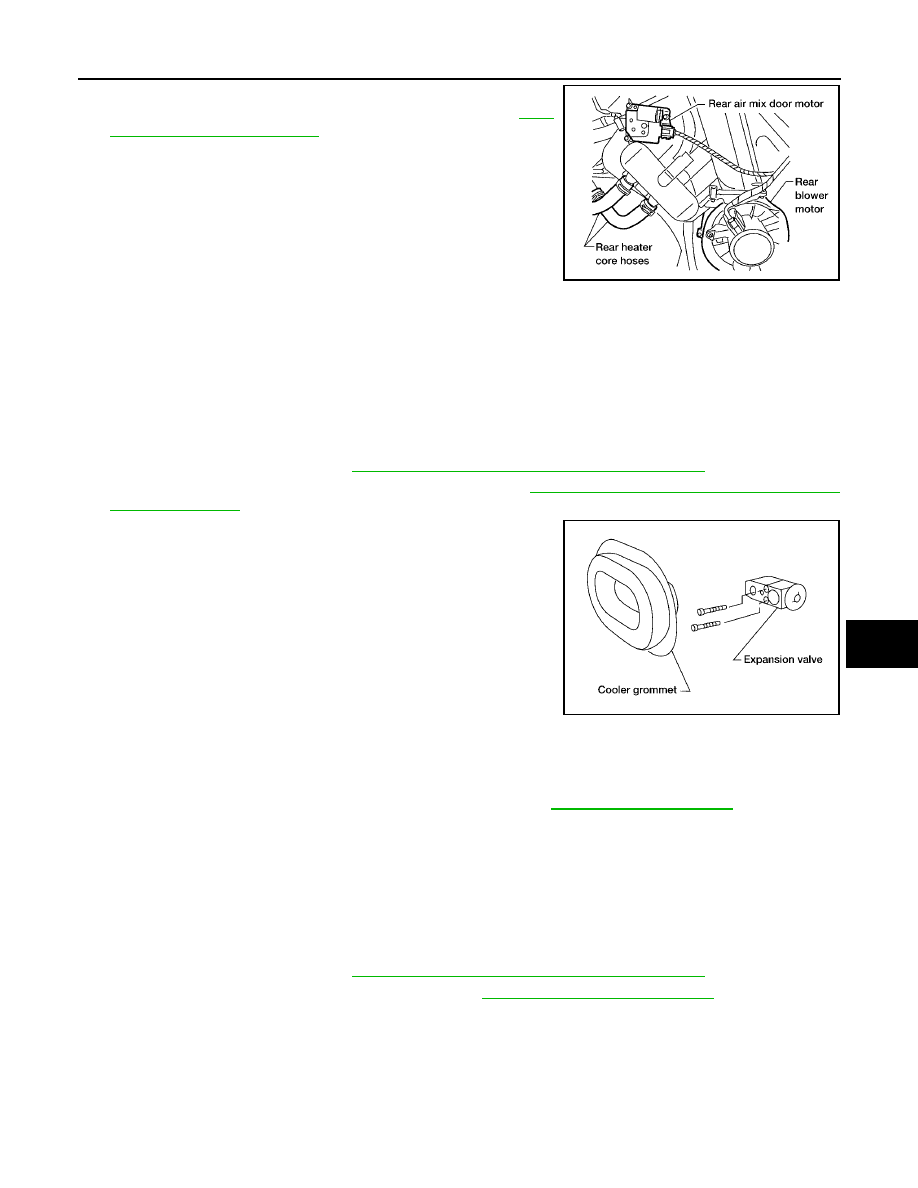
REFRIGERANT LINES
ATC-171
C
D
E
F
G
H
I
K
L
M
A
B
ATC
Revision: May 2004
2004 Quest
4.
Remove the rear air mix door motor.
5.
Remove the rear duct and blend door assembly. Refer to
6.
Disassemble the rear heater and cooling unit assembly to
remove the evaporator.
INSTALLATION
Installation is in the reverse order of removal.
CAUTION:
●
Replace the O-rings on the rear A/C pipes with new ones. Apply compressor oil to the O-rings
before installing them.
●
After charging refrigerant, check for leaks
Removal and Installation for Front Expansion Valve
EJS001TY
REMOVAL
1.
Discharge the refrigerant. Refer to
ATC-158, "HFC-134a (R-134a) Service Procedure"
.
2.
Remove the front heater and cooling unit assembly. Refer to
ATC-136, "FRONT HEATER AND COOLING
3.
Remove the cooler grommet.
4.
Remove the expansion valve.
INSTALLATION
Installation is in the reverse order of removal.
CAUTION:
●
Replace the O-rings on the A/C refrigerant pipes with new ones, then apply compressor oil to them
when installing them.
●
After charging refrigerant, check for leaks
Removal and Installation for Rear Expansion Valve
EJS001OQ
REMOVAL
1.
Discharge the refrigerant. Refer to
ATC-158, "HFC-134a (R-134a) Service Procedure"
.
2.
Remove the rear RH interior side trim panel. Refer to
.
3.
Disconnect the A/C refrigerant pipes from the expansion valve.
CAUTION:
Cap or wrap the A/C refrigerant pipe ends with a suitable material such as vinyl tape to avoid the
entry of air and contaminants.
4.
Remove the expansion valve.
LJIA0021E
WJIA0128E
Expansion valve bolts
: 4 N·m (0.4 kg-m, 35 in-lb)
A/C refrigerant pipe to expansion valve bolt
: Refer to
.

ATC-172
REFRIGERANT LINES
Revision: May 2004
2004 Quest
INSTALLATION
Installation is in the reverse order of removal.
CAUTION:
●
Replace the O-rings on the A/C refrigerant pipes with new ones, then apply compressor oil to them
when installing them.
●
After charging refrigerant, check for leaks
Checking for Refrigerant Leaks
EJS001OR
Perform a visual inspection of all refrigeration parts, fittings, hoses and components for signs of A/C lubricant
leakage, damage, and corrosion. Any A/C lubricant leakage may indicate an area of refrigerant leakage. Allow
extra inspection time in these areas when using either an electronic refrigerant leak detector (J-41995) or fluo-
rescent dye leak detector (J-42220).
If any dye is observed using a fluorescent dye leak detector (J-42220), confirm the leak using a electronic
refrigerant leak detector (J-41995). It is possible that the dye is from a prior leak that was repaired and not
properly cleaned.
When searching for leaks, do not stop when one leak is found but continue to check for additional leaks at all
system components and connections.
When searching for refrigerant leaks using an electronic refrigerant leak detector (J-41995), move the probe
along the suspected leak area at 25 - 50 mm (1 - 2 in) per second and no further than 6 mm (1/4 in) from the
component.
CAUTION:
Moving the electronic refrigerant leak detector probe slower and closer to the suspected leak area will
improve the chances of finding a leak.
Checking System for Leaks Using the Fluorescent Dye Leak Detector
EJS001OS
1.
Check the A/C system for leaks using the fluorescent dye leak detector (and safety goggles) (J-42220) in
a low sunlight area (area without windows preferable). Illuminate all components, fittings and lines. The
dye will appear as a bright green/yellow area at the point of leakage. Fluorescent dye observed at the
evaporator drain opening indicates an evaporator core assembly leak (tubes, core or expansion valve).
2.
If the suspected area is difficult to see, use an adjustable mirror or wipe the area with a clean shop rag or
cloth, then inspect the shop rag or cloth with the fluorescent dye leak detector (J-42220) for dye residue.
3.
After the leak is repaired, remove any residual dye using dye cleaner (J-43872) to prevent future misdiag-
nosis.
4.
Perform a system performance check and then verify the leak repair using a electronic refrigerant leak
detector (J-41995).
NOTE:
●
Other gases in the work area or substances on the A/C components, for example, anti-freeze, wind-
shield washer fluid, solvents and lubricants, may falsely trigger the leak detector. Make sure the sur-
faces to be checked are clean.
●
Clean with a dry cloth or blow off with shop air.
●
Do not allow the sensor tip of the electronic refrigerant leak detector (J-41995) to contact with any sub-
stance. This can also cause false readings and may damage the detector.
Dye Injection
EJS001OT
NOTE:
This procedure is only necessary when recharging the system or when the compressor has seized and must
be replaced.
1.
Check the A/C system static (at rest) pressure. Pressure must be at least 345 kPa (3.52 kg/cm
2
, 50 psi).
2.
Pour one bottle 7.4 cc (1/4 ounce) of the HFC-134a (R-134a) fluorescent leak detection dye (J-41447) into
the HFC-134a (R-134a) dye injector (J-41459).
Expansion valve bolts
: 4 N·m (0.4 kg-m, 35 in-lb)
A/C refrigerant pipe to expansion valve bolt
: Refer to
.
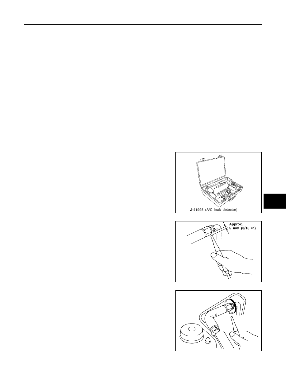
REFRIGERANT LINES
ATC-173
C
D
E
F
G
H
I
K
L
M
A
B
ATC
Revision: May 2004
2004 Quest
CAUTION:
If repairing the A/C system or replacing a component, pour the HFC-134a (R-134a) fluorescent leak
detection dye (J-41447) directly into the open system connection and proceed with the service
procedures.
3.
Connect the injector tool (J-41459) to the low-pressure service valve.
4.
Start the engine and switch the A/C system ON.
5.
When the A/C system is operating (compressor running), inject one bottle 7.4 cc (1/4 ounce) of HFC-134a
(R-134a) fluorescent leak detection dye (J-41447) through the low-pressure service valve using HFC-
134a (R-134a) dye injector (J-41459). Refer to the manufacturer's operating instructions.
6.
With the engine still running, disconnect the HFC-134a (R-134a) dye injector (J-41459) from the low-pres-
sure service valve.
7.
Operate the A/C system for a minimum of 20 minutes to mix the HFC-134a (R-134a) fluorescent leak
detection dye (J-41447) with the A/C system oil. Depending on the leak size, operating conditions and
location of the leak, it may take from minutes to days for the HFC-134a (R-134a) fluorescent leak detec-
tion dye to penetrate an A/C system leak and become visible.
Electronic Refrigerant Leak Detector
EJS001OU
PRECAUTIONS FOR HANDLING LEAK DETECTOR
NOTE:
When performing a refrigerant leak check, use a electronic refrigerant leak detector (J-41995) or equivalent.
Ensure that the electronic refrigerant leak detector (J-41995) is calibrated and set properly according to the
manufacturer's operating instructions.
The electronic refrigerant leak detector (J-41995) is a delicate
device. To use the leak detector properly, read the manufacturer's
operating instructions and perform any specified maintenance.
1.
Position the probe approximately 5 mm (3/16 in) away from the
point to be checked as shown.
2.
When checking for leaks, circle each fitting completely with the
probe as shown.
SHA196FA
SHA707EA
SHA706E
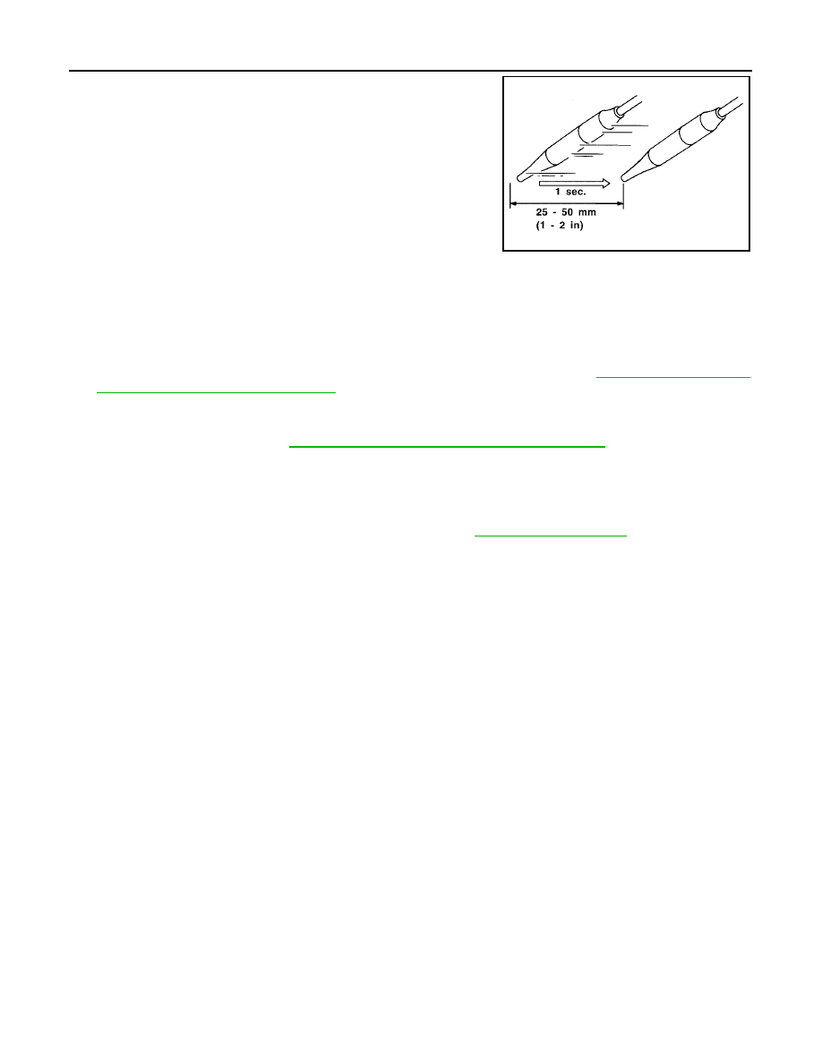
ATC-174
REFRIGERANT LINES
Revision: May 2004
2004 Quest
3.
Move the probe along each component at a speed of approxi-
mately 25 - 50 mm (1 - 2 in)/second as shown.
CHECKING PROCEDURE
NOTE:
To prevent inaccurate or false readings, make sure there is no refrigerant vapor, shop chemicals, or cigarette
smoke in the vicinity of the vehicle. Perform the leak test in a calm area (low air/wind movement) so that the
leaking refrigerant is not dispersed.
1.
Turn the engine OFF.
2.
Connect the manifold gauge set (J-39183-C) to the A/C service ports. Refer to
3.
Check if the A/C refrigerant pressure is at least 345 kPa (3.52 kg/cm
2
, 50 psi) above a temperature of
16
°
C (61
°
F). If less than specification, recover/evacuate and recharge the system with the specified
amount of refrigerant. Refer to
ATC-158, "HFC-134a (R-134a) Service Procedure"
NOTE:
At temperatures below 16
°
C (61
°
F), leaks may not be detected since the system may not reach 345 kPa
(3.52 kg/cm
2
, 50 psi) pressure.
4.
Conduct the leak test from the high pressure side (compressor discharge to evaporator inlet) to the low
pressure side (evaporator drain hose to shaft seal). Refer to
nent to be checked and carefully move the electronic refrigerant leak detector probe completely around
the following connections and components.
●
Compressor
●
High and low-pressure pipe and hose fittings, relief valve, and compressor shaft seal
●
Liquid tank
●
Refrigerant pressure sensor
●
Service valves. Check all around the service valves. Ensure service valve caps are secured on the ser-
vice valves (to prevent leaks).
NOTE:
After removing manifold gauge set (J-39183-C) from the service valves, wipe any residue from the ser-
vice valves to prevent any false readings by the electronic refrigerant leak detector (J-41995).
●
Evaporator
With engine OFF, turn blower fan on “High” for at least 15 seconds to dissipate any refrigerant trace in
the heater and cooling unit assembly. Wait a minimum of 10 minutes accumulation time (refer to the
manufacturer's recommended procedure for actual wait time) before inserting the electronic refrigerant
leak detector probe into the heater and cooling unit assembly drain hose.
NOTE:
Keep the probe inserted for at least 10 seconds. Use caution not to contaminate the probe tip with
water or dirt that may be in the drain hose.
5.
If a leak is detected, verify at least once by blowing compressed air into the area of the suspected leak,
then repeat the leak check.
6.
Do not stop when one leak is found. Continue to check for additional leaks at all system components and
connections.
7.
If no leaks are found, perform steps 8 - 11.
8.
Start the engine.
9.
Set the heater A/C controls as follows:
SHA708EA
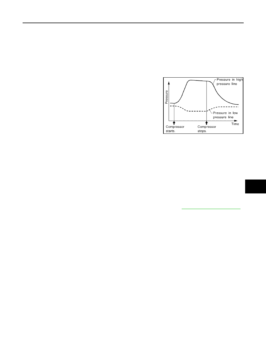
REFRIGERANT LINES
ATC-175
C
D
E
F
G
H
I
K
L
M
A
B
ATC
Revision: May 2004
2004 Quest
NOTE:
For the automatic system, turn OFF the automatic controls and set the heater A/C controls manually.
a.
A/C switch to ON
b.
Air flow to VENT mode
c.
Intake position to RECIRCULATION mode
d.
Temperature to MAX cold
e.
Blower speed to HIGH
10. Run the engine at 1,500 rpm for at least 2 minutes.
11. Turn the engine OFF and perform the leak check again following
steps 4 through 6 above.
Refrigerant leaks should be checked immediately after turning
the engine OFF. Begin with the leak detector at the compressor.
The pressure on the high pressure side will gradually drop after
the refrigerant circulation stops and pressure on the low pres-
sure side will gradually rise, as shown in the graph. Some leaks
are more easily detected when the pressure is high.
12. Before connecting the recovery/recycling recharging equipment (ACR2000) (J-43600) to the vehicle,
check the recovery/recycling recharging equipment (ACR2000) (J-43600) gauges. No refrigerant pres-
sure should be displayed. If pressure is displayed, recover the refrigerant from the equipment lines and
then check the refrigerant purity.
13. Confirm refrigerant purity in supply tank using recovery/recycling recharging equipment (ACR2000) (J-
43600) and refrigerant identifier equipment (J-41810-NI).
14. Confirm the refrigerant purity in the vehicle's A/C system using recovery/recycling recharging equipment
(ACR2000) (J-43600) and refrigerant identifier equipment (J-41810-NI).
15. Discharge the A/C system using recovery/recycling recharging equipment (ACR2000) (J-43600). Repair
the leaking fitting or component as necessary.
16. Evacuate and recharge the A/C system and perform the leak test to confirm that there are no refrigerant
leaks.
17. Conduct the Operational Check to ensure system works properly. Refer to
SHA839E

ATC-176
SERVICE DATA AND SPECIFICATIONS (SDS)
Revision: May 2004
2004 Quest
SERVICE DATA AND SPECIFICATIONS (SDS)
PFP:00030
Service Data and Specifications (SDS)
EJS001OV
COMPRESSOR
LUBRICANT
REFRIGERANT
ENGINE IDLING SPEED
EC-34, "Idle Speed and Ignition Timing Check"
BELT TENSION
Make
ZEXEL VALEO CLIMATE CONTROL
Model
DKS-17D
Type
Swash plate
Displacement
cm3 (cu in)/rev
175.5 (10.7)/rev
Cylinder bore
×
stroke
mm (in)
30.5 (1.20) x 24.0 (0.94)
Direction of rotation
Clockwise (viewed from drive end)
Drive belt
Poly V
Make
ZEXEL VALEO CLIMATE CONTROL
Model
DKS-17D
Name
NISSAN A/C System lubricant Types (DH-PS)
Part number
KLH00-PAGS0
Capacity
m
(US fl oz, lmp fl oz)
Total in system
220 (7.4, 7.7)
Compressor (Service part) charg-
ing amount
220 (7.4, 7.7) Refer to
Type
HFC-134a (R-134a)
Capacity
g (oz)
900
±
50 (31.74
±
1.76)
Document Outline
- QUICK REFERENCE INDEX
- Table of Contents
- PRECAUTIONS
- Precautions for Supplemental Restraint System (SRS) “AIR BAG” and “SEAT BELT PRE-TENSIONER”
- Precautions for Working with HFC-134a (R-134a)
- Contaminated Refrigerant
- General Refrigerant Precautions
- Precautions for Leak Detection Dye
- A/C Identification Label
- Precautions for Refrigerant Connection
- Precautions for Servicing Compressor
- Precautions for Service Equipment
- Wiring Diagrams and Trouble Diagnosis
- PREPARATION
- REFRIGERATION SYSTEM
- LUBRICANT
- AIR CONDITIONER CONTROL
- Description
- Operation
- Description of Control System
- Control Operation
- DISPLAY SCREEN
- AUTO SWITCH
- TEMPERATURE SWITCH (TEMPERATURE CONTROL) (DRIVER SIDE)
- TEMPERATURE SWITCH (TEMPERATURE CONTROL) (PASSENGER SIDE)
- TEMPERATURE SWITCH (TEMPERATURE CONTROL) (REAR)
- RECIRCULATION () SWITCH
- DEFROSTER (DEF) SWITCH
- REAR WINDOW DEFOGGER SWITCH
- OFF SWITCH
- A/C SWITCH
- MODE SWITCH
- FRONT FAN CONTROL SWITCH
- REAR FAN CONTROL SWITCH
- Discharge Air Flow
- System Description
- CAN Communication System Description
- TROUBLE DIAGNOSIS
- CONSULT-II
- How to Perform Trouble Diagnosis for Quick and Accurate Repair
- Component Parts and Harness Connector Location
- Schematic
- Wiring Diagram —A/C—
- Intake Front Air Control Terminals and Reference Value
- A/C System Self-diagnosis Function
- Operational Check
- Power Supply and Ground Circuit for Front Air Control
- Mode Door Motor Circuit
- Air Mix Door Motor Circuit
- Intake Door Motor Circuit
- Defroster Door Motor Circuit
- Front Blower Motor Circuit
- Rear Blower Motor Circuit
- Rear Air Control Circuit
- Magnet Clutch Circuit
- Insufficient Cooling
- INSPECTION FLOW
- PERFORMANCE TEST DIAGNOSES
- PERFORMANCE CHART
- Trouble Diagnoses for Unusual Pressure
- Both High- and Low-pressure Sides are Too High
- High-pressure Side is Too High and Low-pressure Side is Too Low
- High-pressure Side is Too Low and Low-pressure Side is Too High
- Both High- and Low-pressure Sides are Too Low
- Low-pressure Side Sometimes Becomes Negative
- Low-pressure Side Becomes Negative
- Insufficient Heating
- Noise
- Self-diagnosis
- Memory Function
- Ambient Sensor Circuit
- In-vehicle Sensor Circuit
- Optical Sensor Circuit
- Intake Sensor Circuit
- CONTROL UNIT
- AMBIENT SENSOR
- IN-VEHICLE SENSOR
- OPTICAL SENSOR
- INTAKE SENSOR
- BLOWER MOTOR
- IN-CABIN MICROFILTER
- HEATER & COOLING UNIT ASSEMBLY
- HEATER CORE
- HEATER PUMP
- DEFROSTER DOOR MOTOR
- INTAKE DOOR MOTOR
- MODE DOOR MOTOR
- AIR MIX DOOR MOTOR
- VARIABLE BLOWER CONTROL
- REAR BLOWER MOTOR RESISTOR
- DUCTS AND GRILLES
- REFRIGERANT LINES
- HFC-134a (R-134a) Service Procedure
- Components
- Removal and Installation for Compressor
- Removal and Installation for Compressor Clutch
- Removal and Installation for Low-pressure Flexible Hose
- Removal and Installation for High-pressure Flexible Hose
- Removal and Installation for High-pressure Pipe
- Removal and Installation for High/Low-pressure Pipe
- Removal and Installation for Refrigerant Pressure Sensor
- Removal and Installation for Condenser
- Removal and Installation for Front Evaporator
- Removal and Installation for Rear Evaporator
- Removal and Installation for Front Expansion Valve
- Removal and Installation for Rear Expansion Valve
- Checking for Refrigerant Leaks
- Checking System for Leaks Using the Fluorescent Dye Leak Detector
- Dye Injection
- Electronic Refrigerant Leak Detector
- SERVICE DATA AND SPECIFICATIONS (SDS)
- PRECAUTIONS
- ELECTRICAL UNITS
- SUPER MULTIPLE JUNCTION (SMJ)
- FUSE BLOCK-JUNCTION BOX(J/B)
- FUSE AND FUSIBLE LINK BOX
Wyszukiwarka
Podobne podstrony:
ATC
Pudełko na ATC, Rękodzieło, Kartki
CHEMIA, Zastosowanie Gliceryny, Gliceryna (glicerol; ATC: A 06 AX 01) - organiczny związek chemiczny
Bydgoszcz, Masci sterydowe podzial, Podział sterydów stosowanych miejscowo wg Klasyfikacji ATC:
Frazeologia ATC, Lotnictwo, ppl, Radio, korespondencja, Radio
Atc
Procedury ATC
ATC
Frazeologia ATC
Around the world ATC
Around the world ATC
ATC
atcgrupa pl ATC GRUPA oferta szkole Pozna Gosty ATC Grupa Szkolenia i kursy Pozna Gosty Wielkopolska
Thinking of you ATC
więcej podobnych podstron