
ATC-1
AUTOMATIC AIR CONDITIONER
J AIR CONDITIONER
CONTENTS
C
D
E
F
G
H
I
K
L
M
SECTION
ATC
A
B
ATC
AUTOMATIC AIR CONDITIONER
PRECAUTIONS .......................................................... 4
Precautions for Supplemental Restraint System
(SRS) “AIR BAG” and “SEAT BELT PRE-TEN-
SIONER” .................................................................. 4
PrecautionsforProcedureswithoutCowlTop Cover..... 4
Precautions for Working with HFC-134a (R-134a)..... 4
General Refrigerant Precautions .............................. 4
Lubricant Precautions .............................................. 5
Precautions for Refrigerant Connection ................... 5
FEATURES OF NEW TYPE REFRIGERANT
CONNECTION ...................................................... 5
O-RING AND REFRIGERANT CONNECTION..... 6
RECOVERY/RECYCLING EQUIPMENT .............. 8
ELECTRONIC LEAK DETECTOR ........................ 8
VACUUM PUMP ................................................... 9
MANIFOLD GAUGE SET ...................................... 9
SERVICE HOSES ................................................. 9
SERVICE COUPLERS ........................................ 10
REFRIGERANT WEIGHT SCALE ...................... 10
CALIBRATING ACR4 WEIGHT SCALE .............. 10
CHARGING CYLINDER ...................................... 10
Precautions for Leak Detection Dye ........................11
PREPARATION ......................................................... 12
HFC-134a (R-134a) Service Tools and Equipment... 12
Commercial Service Tools ...................................... 14
REFRIGERATION SYSTEM ..................................... 15
Refrigerant Cycle ................................................... 15
Refrigerant System Protection ............................... 15
REFRIGERANT PRESSURE SENSOR ............. 15
PRESSURE RELIEF VALVE ............................... 15
Component Layout ................................................. 16
LUBRICANT .............................................................. 17
Maintenance of Lubricant Quantity in Compressor... 17
LUBRICANT ........................................................ 17
LUBRICANT RETURN OPERATION .................. 17
LUBRICANT ADJUSTING PROCEDURE FOR
COMPONENTS REPLACEMENT EXCEPT
COMPRESSOR .................................................. 18
LUBRICANT ADJUSTING PROCEDURE FOR
COMPRESSOR REPLACEMENT ....................... 18
AIR CONDITIONER CONTROL ............................... 20
System Construction .............................................. 20
AIR MIX DOOR CONTROL (AUTOMATIC TEM-
PERATURE CONTROL) ..................................... 20
FAN SPEED CONTROL ...................................... 20
INTAKE DOOR CONTROL ................................. 20
OUTLET DOOR CONTROL ................................ 20
MAGNET CLUTCH CONTROL ........................... 21
SELF-DIAGNOSTIC SYSTEM ............................ 21
Discharge Air Flow ................................................. 24
System Description ................................................. 25
SWITCHES AND THEIR CONTROL FUNCTION... 25
CAN Communication System Description .............. 25
TROUBLE DIAGNOSIS ............................................ 26
CONSULT-II Function (BCM) ................................. 26

ATC-2
Component Parts and Harness Connector Location... 28
ENGINE COMPARTMENT .................................. 28
PASSENGER COMPARTMENT .......................... 29
Circuit Diagram ....................................................... 30
Wiring Diagram —A/C— CR Engine Models .......... 31
Wiring Diagram —A/C—HR Engine Models ........... 35
Wiring Diagram —A/C— K9K Engine Models ........ 39
Wiring Diagram —PTC/H— K9K Engine LHD Mod-
els ........................................................................... 43
Auto Amp. Terminals and Reference Value ............ 44
Self-diagnosis Function .......................................... 46
DESCRIPTION .................................................... 46
FUNCTION CONFIRMATION PROCEDURE ...... 48
AUXILIARY MECHANISM: TEMPERATURE
SETTING TRIMMER ........................................... 54
Operational Check .................................................. 55
CHECKING MEMORY FUNCTION ..................... 55
CHECKING BLOWER ......................................... 55
CHECKING DISCHARGE AIR ............................ 55
CHECKING RECIRCULATION ............................ 56
CHECKING TEMPERATURE INCREASE .......... 56
CHECKING TEMPERATURE DECREASE ......... 56
CHECK A/C SWITCH .......................................... 56
CHECKING AUTO MODE ................................... 57
Power Supply and Ground Circuit for Auto Amp. ... 57
INSPECTION FLOW ........................................... 57
COMPONENT DESCRIPTION ............................ 58
DIAGNOSTIC PROCEDURE FOR A/C SYSTEM... 58
Mode Door Motor Circuit ........................................ 60
INSPECTION FLOW ........................................... 60
SYSTEM DESCRIPTION .................................... 61
COMPONENT DESCRIPTION ............................ 62
DIAGNOSTIC PROCEDURE FOR MODE
DOOR MOTOR ................................................... 63
Air Mix Door Motor Circuit ...................................... 64
INSPECTION FLOW ........................................... 64
SYSTEM DESCRIPTION .................................... 65
COMPONENT DESCRIPTION ............................ 66
DIAGNOSTIC PROCEDURE FOR AIR MIX
DOOR MOTOR ................................................... 67
Intake Door Motor Circuit ........................................ 68
INSPECTION FLOW ........................................... 68
SYSTEM DESCRIPTION .................................... 69
COMPONENT DESCRIPTION ............................ 70
DIAGNOSTIC PROCEDURE FOR INTAKE
DOOR MOTOR ................................................... 70
Blower Motor Circuit ............................................... 71
INSPECTION FLOW ........................................... 71
SYSTEM DESCRIPTION .................................... 72
DIAGNOSTIC PROCEDURE FOR BLOWER
MOTOR ............................................................... 73
COMPONENT INSPECTION .............................. 77
Magnet Clutch Circuit ..............................................78
INSPECTION FLOW ............................................78
SYSTEM DESCRIPTION .....................................79
DIAGNOSTIC PROCEDURE FOR MAGNET
CLUTCH ..............................................................79
COMPONENT INSPECTION ...............................85
Insufficient Cooling ..................................................86
INSPECTION FLOW ............................................86
PERFORMANCE TEST DIAGNOSIS ..................88
PERFORMANCE CHART ....................................90
TROUBLE DIAGNOSIS FOR UNUSUAL PRES-
SURE ...................................................................91
Insufficient Heating .................................................94
INSPECTION FLOW ............................................94
Noise .......................................................................96
INSPECTION FLOW ............................................96
Self-diagnosis .........................................................97
INSPECTION FLOW ............................................97
Memory Function ....................................................98
INSPECTION FLOW ............................................98
Ambient Sensor Circuit ...........................................99
COMPONENT DESCRIPTION ............................99
AMBIENT TEMPERATURE INPUT PROCESS...99
DIAGNOSTIC PROCEDURE FOR AMBIENT
SENSOR ..............................................................99
COMPONENT INSPECTION .............................101
In-vehicle Sensor Circuit .......................................102
COMPONENT DESCRIPTION ..........................102
DIAGNOSTIC PROCEDURE FOR IN-VEHICLE
SENSOR ............................................................102
COMPONENT INSPECTION .............................104
Sunload Sensor Circuit .........................................105
COMPONENT DESCRIPTION ..........................105
SUNLOAD INPUT PROCESS ...........................105
DIAGNOSTIC PROCEDURE FOR SUNLOAD
SENSOR ............................................................105
COMPONENT INSPECTION .............................107
Intake Sensor Circuit .............................................108
COMPONENT DESCRIPTION ..........................108
DIAGNOSTIC PROCEDUREFOR INTAKESEN-
SOR ...................................................................108
COMPONENT INSPECTION ............................. 110
Engine Coolant Temperature Circuit ..................... 111
CONTROLLER ........................................................ 112
Removal and Installation of Controller .................. 112
Disassembly and Assembly of Controller ............. 112
DISASSEMBLY .................................................. 112
ASSEMBLY ........................................................ 113
AMBIENT SENSOR ................................................ 114
Removal and Installation ....................................... 114
IN-VEHICLE SENSOR ............................................ 115
Removal and Installation ....................................... 115

ATC-3
C
D
E
F
G
H
I
K
L
M
A
B
ATC
SUNLOAD SENSOR ...............................................116
Removal and Installation .......................................116
INTAKE SENSOR ....................................................117
Removal and Installation .......................................117
A/C UNIT ASSEMBLY .............................................118
Removal and Installation .......................................118
REMOVAL ..........................................................118
INSTALLATION ................................................. 120
Disassembly and Assembly ................................. 121
BLOWER MOTOR .................................................. 123
Removal and Installation ...................................... 123
INTAKE DOOR MOTOR ......................................... 124
Removal and Installation ...................................... 124
AIR MIX DOOR MOTOR ......................................... 125
Removal and Installation ...................................... 125
MODE DOOR MOTOR ........................................... 126
Removal and Installation ...................................... 126
POWER TRANSISTOR .......................................... 127
Removal and Installation ...................................... 127
HEATER CORE ...................................................... 128
Removal and Installation ...................................... 128
AIR CONDITIONER FILTER ................................... 129
Removal and Installation ...................................... 129
DUCTS AND GRILLES .......................................... 130
Removal and Installation ...................................... 130
REMOVAL ......................................................... 130
INSTALLATION ................................................. 134
REFRIGERANT LINES ........................................... 135
HFC-134a (R-134a) Service Procedure ............... 135
Components ......................................................... 137
CR ENGINE MODELS ...................................... 137
HR ENGINE MODELS ...................................... 138
K9K ENGINE MODELS ..................................... 139
Removal and Installation of Compressor .............. 140
REMOVAL ......................................................... 140
INSTALLATION ................................................. 140
CHECK DISC TO PULLEY CLEARANCE ......... 141
Removal and Installation for Pipe and Hose ........ 141
REMOVAL AND INSTALLATION ...................... 142
REMOVAL ......................................................... 142
INSTALLATION ................................................. 143
REMOVAL ......................................................... 144
INSTALLATION ................................................. 145
Removal and Installation for Evaporator .............. 145
Removal and Installation for Expansion Valve ...... 145
REMOVAL ......................................................... 145
INSTALLATION ................................................. 146
Checking for Refrigerant Leaks ............................ 147
Checking System for Leaks Using the Fluorescent
Leak Detector ....................................................... 147
Dye Injection ......................................................... 147
Electronic Refrigerant Leak Detector .................... 148
PRECAUTIONS FOR HANDLING LEAK
DETECTOR ....................................................... 148
CHECKING PROCEDURE ............................... 149
ATC-4
PRECAUTIONS
PRECAUTIONS
PFP:00001
Precautions for Supplemental Restraint System (SRS) “AIR BAG” and “SEAT
BELT PRE-TENSIONER”
BJS000AI
The Supplemental Restraint System such as “AIR BAG” and “SEAT BELT PRE-TENSIONER”, used along
with a front seat belt, helps to reduce the risk or severity of injury to the driver and front passenger for certain
types of collision. Information necessary to service the system safely is included in the SRS and SB section of
this Service Manual.
WARNING:
●
To avoid rendering the SRS inoperative, which could increase the risk of personal injury or death
in the event of a collision which would result in air bag inflation, all maintenance must be per-
formed by an authorized NISSAN/INFINITI dealer.
●
Improper maintenance, including incorrect removal and installation of the SRS, can lead to per-
sonal injury caused by unintentional activation of the system. For removal of Spiral Cable and Air
Bag Module, see the SRS section.
●
Do not use electrical test equipment on any circuit related to the SRS unless instructed to in this
Service Manual. SRS wiring harnesses can be identified by yellow and/or orange harnesses or
harness connectors.
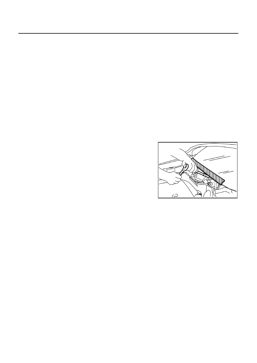
Precautions for Procedures without Cowl Top Cover
BJS000AJ
When performing the procedure after removing cowl top cover, cover
the lower end of windshield with urethane, etc.
Precautions for Working with HFC-134a (R-134a)
BJS000AK
WARNING:
●
Use only specified lubricant for the HFC-134a (R-134a) A/C system and HFC-134a (R-134a) compo-
nents. If lubricant other than that specified is used, compressor malfunction is likely to occur.
●
The specified HFC-134a (R-134a) lubricant rapidly absorbs moisture from the atmosphere. The fol-
lowing handling precautions must be observed:
–
When removing refrigerant components from a vehicle, immediately cap (seal) the component to
minimize the entry of moisture from the atmosphere.
–
When installing refrigerant components to a vehicle, do not remove the caps (unseal) until just
before connecting the components. Connect all refrigerant loop components as quickly as possi-
ble to minimize the entry of moisture into system.
–
Only use the specified lubricant from a sealed container. Immediately reseal containers of lubri-
cant. Without proper sealing, lubricant will become moisture saturated and should not be used.
–
Avoid breathing A/C refrigerant and lubricant vapor or mist. Exposure may irritate eyes, nose and
throat. Use only approved recovery/recycling equipment to discharge HFC-134a (R-134a) refriger-
ant. If accidental system discharge occurs, ventilate work area before resuming service. Addi-
tional
health
and
safety
information
may
be
obtained
from
refrigerant and
lubricant
manufacturers.
–
Do not allow lubricant (Nissan A/C System Oil Type R) to come in contact with styrofoam parts.
Damage may result.
General Refrigerant Precautions
BJS000AL
WARNING:
●
Do not release refrigerant into the air. Use approved recovery/recycling equipment to capture the
refrigerant every time an air conditioning system is discharged.
PIIB3706J

PRECAUTIONS
ATC-5
C
D
E
F
G
H
I
K
L
M
A
B
ATC
●
Always wear eye and hand protection (goggles and gloves) when working with any refrigerant or
air conditioning system.
●
Do not store or heat refrigerant containers above 52
°
C.
●
Do not heat a refrigerant container with an open flame; if container warming is required, place the
bottom of the container in a warm pail of water.
●
Do not intentionally drop, puncture, or incinerate refrigerant containers.
●
Keep refrigerant away from open flames: poisonous gas will be produced if refrigerant burns.
●
Refrigerant will displace oxygen, therefore be certain to work in well ventilated areas to prevent
suffocation.
●
Do not pressure test or leak test HFC-134a (R-134a) service equipment and/or vehicle air condi-
tioning systems with compressed air during repair. Some mixtures of air and HFC-134a (R-134a)
have been shown to be combustible at elevated pressures. These mixtures, if ignited, may cause
injury or property damage. Additional health and safety information may be obtained from refriger-
ant manufacturers.
Lubricant Precautions
BJS000AM
●
Use only specified lubricant for the HFC-134a (R-134a) A/C system and HFC-134a (R-134a) components.
If lubricant other than that specified is used, compressor malfunction is likely to occur.
●
The specified HFC-134a (R-134a) lubricant rapidly absorbs moisture from the atmosphere. The following
handling precautions must be observed:
–
When removing refrigerant components from a vehicle, immediately cap (seal) the component to minimize
the entry of moisture from the atmosphere.
–
When installing refrigerant components to a vehicle, do not remove the caps (unseal) until just before con-
necting the components. Connect all refrigerant loop components as quickly as possible to minimize the
entry of moisture into system.
–
Only use the specified lubricant from a sealed container. Immediately reseal containers of lubricant. With-
out proper sealing, lubricant will become moisture saturated and should not be used.
●
Avoid breathing A/C refrigerant and lubricant vapor or mist. Exposure may irritate eyes, nose and throat.
Use only approved recovery/recycling equipment to discharge HFC-134a (R-134a) refrigerant. If acciden-
tal system discharge occurs, ventilate work area before resuming service. Additional health and safety
information may be obtained from refrigerant and lubricant manufacturers.
●
Do not allow lubricant (Nissan A/C System Oil Type R) to come in contact with styrofoam parts. Damage
may result.
Precautions for Refrigerant Connection
BJS000AN
A new type refrigerant connection has been introduced to all refrigerant lines except the following location.
●
Expansion valve to evaporator
●
Refrigerant pressure sensor to condenser
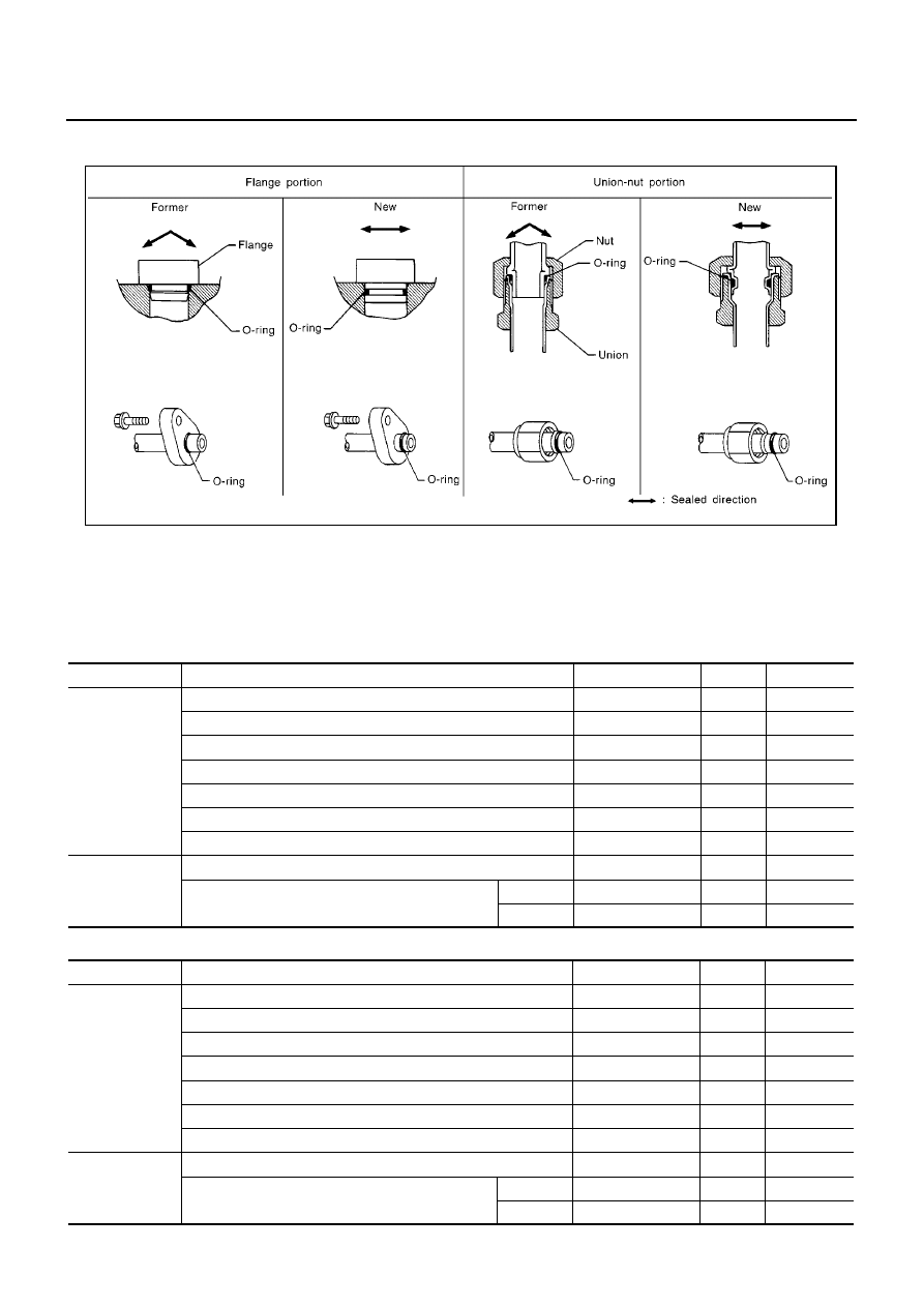
FEATURES OF NEW TYPE REFRIGERANT CONNECTION
●
The O-ring has been relocated. It has also been provided with a groove for proper installation. This elimi-
nates the chance of the O-ring being caught in, or damaged by, the mating part. The sealing direction of
the O-ring is now set vertically in relation to the contacting surface of the mating part to improve sealing
characteristics.
ATC-6
PRECAUTIONS
●
The reaction force of the O-ring will not occur in the direction that causes the joint to pull out, thereby facil-
itating piping connections.
O-RING AND REFRIGERANT CONNECTION
CAUTION:
The new and former refrigerant connections use different O-ring configurations. Do not confuse O-
rings since they are not interchangeable. If a wrong O-ring is installed, refrigerant will leak at, or
around, the connection.
O-Ring Part Numbers and Specifications (CR Engine Models)
O-Ring Part Numbers and Specifications (HR Engine Models)
SHA815E
Connection type
Piping connection point
Part number
Qty.
Remarks
New
Low-pressure flexible hose to heater & cooling unit
92473 BC700
1
High-pressure pipe to heater & cooling unit
92471 BC700
1
Condenser to high-pressure flexible hose
92472 BC700
1
Condenser to high-pressure pipe
92471 BC700
1
Compressor to low-pressure flexible hose
92474 BC700
1
Compressor to high-pressure flexible hose
92472 BC700
1
Liquid tank to condenser pipe
92471 N8210
1
Former
Refrigerant pressure sensor
—
–
Expansion valve to evaporator
Inlet
92477 AX000
1
Outlet
92477 AX005
1
Connection type
Piping connection point
Part number
Qty.
Remarks
New
Low-pressure flexible hose to heater & cooling unit
92473 N8210
1
High-pressure pipe to heater & cooling unit
92471 N8210
1
Condenser to high-pressure flexible hose
92472 N8210
1
Condenser to high-pressure pipe
92471 N8210
1
Compressor to low-pressure flexible hose
92474 N8210
1
Compressor to high-pressure flexible hose
92472 N8210
1
Liquid tank to condenser pipe
92471 N8210
1
Former
Refrigerant pressure sensor
—
–
Expansion valve to evaporator
Inlet
92477 AX000
1
Outlet
92477 AX005
1
PRECAUTIONS
ATC-7
C
D
E
F
G
H
I
K
L
M
A
B
ATC
O-Ring Part Numbers and Specifications (K9K Engine Models)
WARNING:
Make sure all refrigerant is discharged into the recycling equipment and the pressure in the system is
less than atmospheric pressure. Then gradually loosen the discharge side hose fitting and remove it.
CAUTION:
When replacing or cleaning refrigerant cycle components, observe the following.
●
When the compressor is removed, store it in the same position as it is when mounted on the car.
Malfunction to do so will cause lubricant to enter the low-pressure chamber.
●
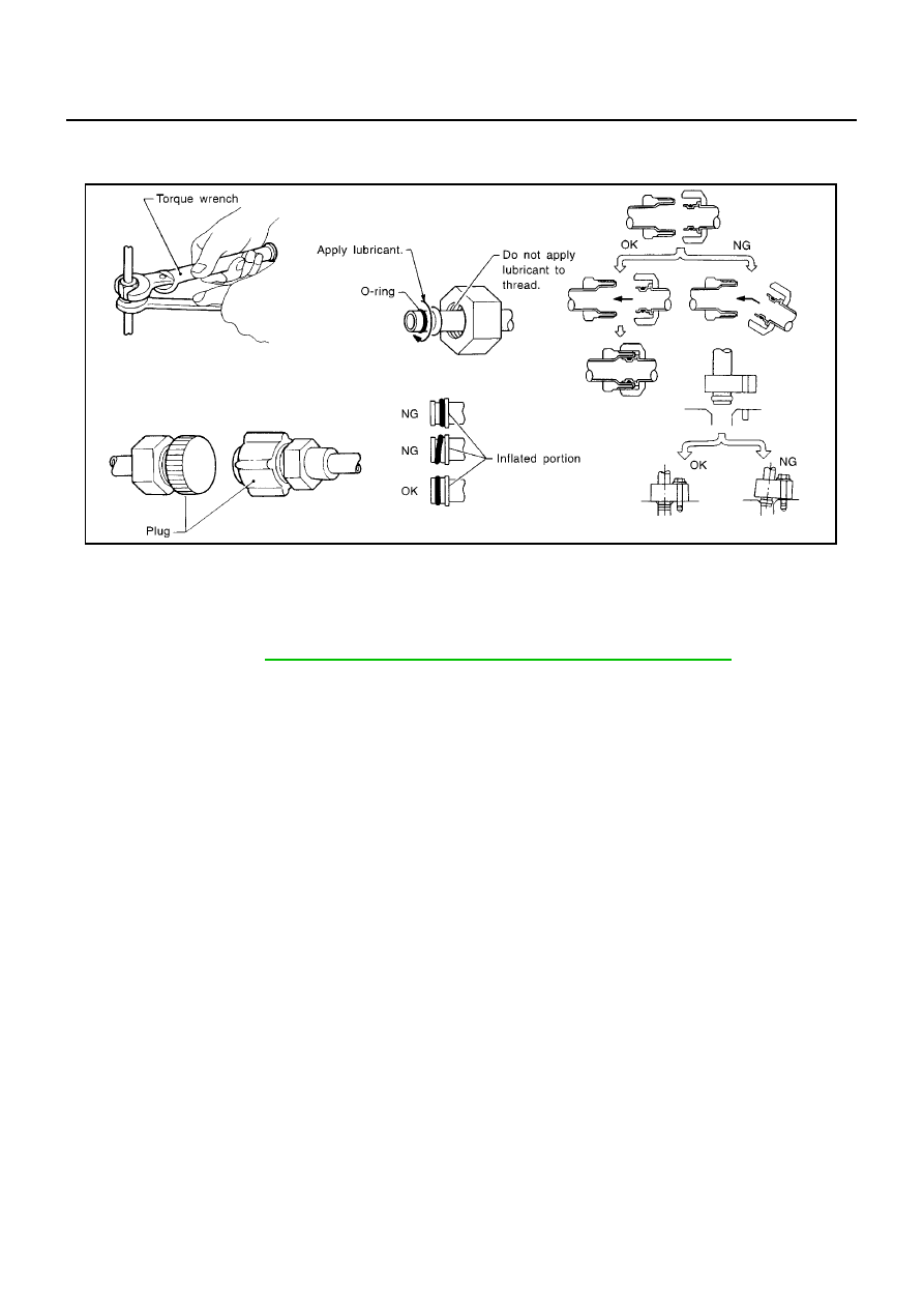
When connecting tubes, always use a torque wrench and a back-up wrench.
●
After disconnecting tubes, immediately plug all openings to prevent entry of dirt and moisture.
●
When installing an air conditioner in the vehicle, connect the pipes as the final stage of the opera-
tion. Do not remove the seal caps of pipes and other components until just before required for
connection.
●
Allow components stored in cool areas to warm to working area temperature before removing seal
caps. This prevents condensation from forming inside A/C components.
●
Thoroughly remove moisture from the refrigeration system before charging the refrigerant.
●
Always replace used O-rings.
●
When connecting tube, apply lubricant to circle of the O-rings shown in illustration. Be careful not
to apply lubricant to threaded portion.
●
O-ring must be closely attached to dented portion of tube.
●
When replacing the O-ring, be careful not to damage O-ring and tube.
●
Connect tube until you hear it click, then tighten the nut or bolt by hand until snug. Make sure that
the O-ring is installed to tube correctly.
Connection type
Piping connection point
Part number
Qty.
Remarks
New
Low-pressure flexible hose to heater & cooling unit
92473 N8210
1
Low-pressure flexible hose to Low-pressure pipe
92473 N8210
1
High-pressure pipe to heater & cooling unit
92471 N8210
1
Condenser to high-pressure flexible hose
92472 N8210
1
Condenser to high-pressure pipe
92471 N8210
1
Compressor to low-pressure flexible hose
92474 N8210
1
Compressor to high-pressure flexible hose
92472 N8210
1
Liquid tank to condenser pipe
92471 N8210
1
Former
Refrigerant pressure sensor
—
–
Expansion valve to evaporator
Inlet
92477 AX000
1
Outlet
92477 AX005
1
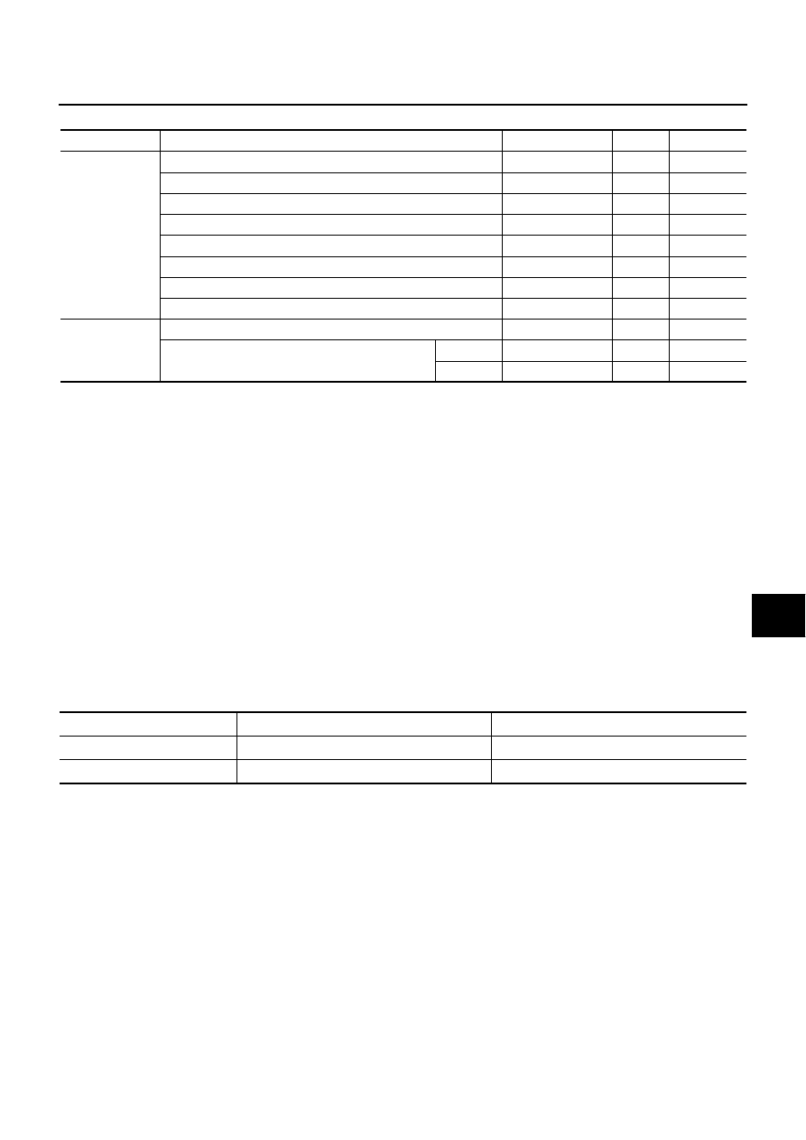
Gasoline engine
K9K engine
Name
Nissan A/C System Oil Type R
Nissan A/C System Oil Type S
Parts number
KLH00 - PAGR0
KLH00 - PAGS0
ATC-8
PRECAUTIONS
●
After connecting line, perform leak test and make sure that there is no leakage from connections.
When the refrigerant leaking point is found, disconnect that line and replace the O-ring. Then
tighten connections of seal seat to the specified torque.
Precautions for Servicing Compressor
BJS000AO
●
Plug all openings to prevent moisture and foreign matter from entering.
●
When the compressor is removed, store it in the same position as it is when mounted on the car.
●
When replacing or repairing compressor, follow “Maintenance of Lubricant Quantity in Compres-
sor” exactly. Refer to
ATC-17, "Maintenance of Lubricant Quantity in Compressor"
.
●
Keep friction surfaces between clutch and pulley clean. If the surface is contaminated, with lubri-
cant, wipe it off by using a clean waste cloth moistened with thinner.
●
After compressor service operation, turn the compressor shaft by hand more than five turns in
both directions. This will equally distribute lubricant inside the compressor. After the compressor
is installed, let the engine idle and operate the compressor for one hour.
●
After replacing the compressor magnet clutch, apply voltage to the new one and check for usual
operation.
Precautions for Service Equipment
BJS000AP
RECOVERY/RECYCLING EQUIPMENT
Be certain to follow the manufacturer’s instructions for machine operation and machine maintenance. Never
introduce any refrigerant other than that specified into the machine.
ELECTRONIC LEAK DETECTOR
Be certain to follow the manufacturer’s instructions for tester operation and tester maintenance.
RHA861F
PRECAUTIONS
ATC-9
C
D
E
F
G
H
I
K
L
M
A
B
ATC
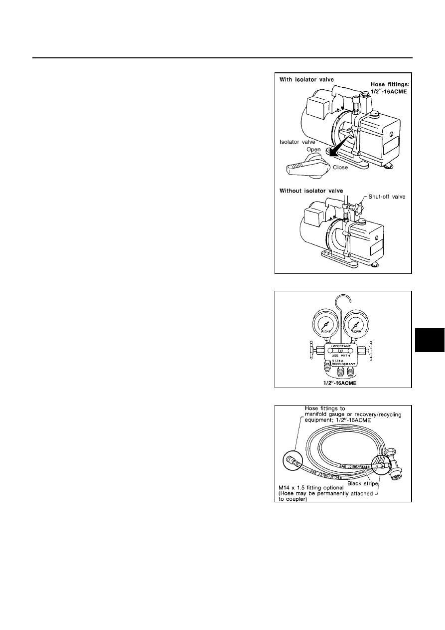
VACUUM PUMP
The lubricant contained inside the vacuum pump is not compatible
with the specified lubricant for HFC-134a (R-134a) A/C systems.
The vent side of the vacuum pump is exposed to atmospheric pres-
sure. So the vacuum pump lubricant may migrate out of the pump
into the service hose. This is possible when the pump is switched off
after evacuation (vacuuming) and hose is connected to it.
To prevent this migration, use a manual valve placed near the hose-
to-pump connection, as follows.
●
Usually vacuum pumps have a manual isolator valve as part of
the pump. Close this valve to isolate the service hose from the
pump.
●
For pumps without an isolator, use a hose equipped with a man-
ual shut-off valve near the pump end. Close the valve to isolate
the hose from the pump.
●
If the hose has an automatic shut-off valve, disconnect the hose
from the pump. As long as the hose is connected, the valve is
open and lubricating oil may migrate.
Some one-way valves open when vacuum is applied and close
under a no vacuum condition. Such valves may restrict the pump’s
ability to pull a deep vacuum and are not recommended.
MANIFOLD GAUGE SET
Be certain that the gauge face indicates HFC-134a or R-134a. Be
sure the gauge set has 1/2
″
-16 ACME threaded connections for ser-
vice hoses. Confirm the set has been used only with refrigerant
HFC-134a (R-134a) and specified lubricants.
SERVICE HOSES
Be certain that the service hoses display the markings described
(colored hose with black stripe). All hoses must include positive shut-
off devices (either manual or automatic) near the end of the hoses
opposite the manifold gauge.
RHA270DA
SHA533D
RHA272D
ATC-10
PRECAUTIONS
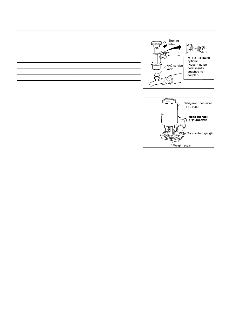
SERVICE COUPLERS
Never attempt to connect HFC-134a (R-134a) service couplers to a
CFC-12 (R-12) A/C system. The HFC-134a (R-134a) couplers will
not properly connect to the CFC-12 (R-12) system. However, if an
improper connection is attempted, discharging and contamination
may occur.
REFRIGERANT WEIGHT SCALE
Verify that no refrigerant other than HFC-134a (R-134a) and speci-
fied lubricants have been used with the scale. If the scale controls
refrigerant flow electronically, the hose fitting must be 1/2
″
-16
ACME.
CALIBRATING ACR4 WEIGHT SCALE
Calibrate the scale every three months.
To calibrate the weight scale on the ACR4:
1.
Press “Shift/Reset” and “Enter” at the same time.
2.
Press “8787” . “A1” will be displayed.
3.
Remove all weight from the scale.
4.
Press “0” , then press “Enter” . “0.00” will be displayed and change to “A2” .
5.
Place a known weight (dumbbell or similar weight), between 4.5 and 8.6 kg (10 and 19 lb) on the center of
the weight scale.
6.
Enter the known weight using four digits. (Example 10 lb = 10.00, 10.5 lb = 10.50)
7.
Press “Enter” — the display returns to the vacuum mode.
8.
Press “Shift/Reset” and “Enter” at the same time.
9.
Press “6” — the known weight on the scale is displayed.
10. Remove the known weight from the scale. “0.00” will be displayed.
11. Press “Shift/Reset” to return the ACR4 to the program mode.
CHARGING CYLINDER
Using a charging cylinder is not recommended. Refrigerant may be vented into air from cylinder’s top valve
when filling the cylinder with refrigerant. Also, the accuracy of the cylinder is generally less than that of an
electronic scale or of quality recycle/recharge equipment.
Shut-off valve rotation
A/C service valve
Clockwise
Open
Counterclockwise
Close
RHA273D
RHA274D
PRECAUTIONS
ATC-11
C
D
E
F
G
H
I
K
L
M
A
B
ATC
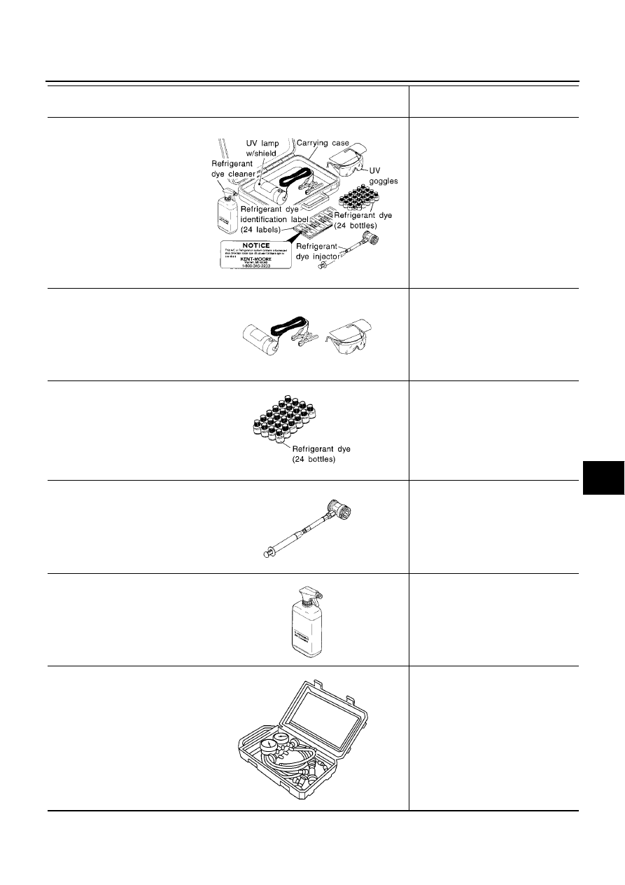
Precautions for Leak Detection Dye
BJS000AQ
●
The A/C system contains a fluorescent leak detection dye used for locating refrigerant leaks. An ultraviolet
(UV) lamp is required to illuminate the dye when inspecting for leaks.
●
Always wear fluorescence enhancing UV safety goggles to protect your eyes and enhance the visibility of
the fluorescent dye.
●
The fluorescent dye leak detector is not a replacement for an electronic refrigerant leak detector. The fluo-
rescent dye leak detector should be used in conjunction with an electronic refrigerant leak detector to pin-
point refrigerant leaks.
●
For your safety and your customer’s satisfaction, read and follow all manufacture’s operating instructions
and precautions prior to performing the work.
●
A compressor shaft seal should not be repaired because of dye seepage. The compressor shaft seal
should only be repaired after confirming the leak with an electronic refrigerant leak detector.
●
Always remove any remaining dye from the leak area after repairs are complete to avoid a misdiagnosis
during a future service.
●
Do not allow dye to come into contact with painted body panels or interior components. If dye is spilled,
clean immediately with the approved dye cleaner. Fluorescent dye left on a surface for an extended period
of time cannot be removed.
●
Do not spray the fluorescent dye cleaning agent on hot surfaces (engine exhaust manifold, etc.).
●
Do not use more than one refrigerant dye bottle (1/4 ounce /7.4 cc) per A/C system.
●
Leak detection dyes for HFC-134a (R-134a) and CFC-12 (R-12) A/C systems are different. Do not use
HFC-134a (R-134a) leak detection dye in CFC-12 (R-12) A/C system or CFC-12 (R-12) leak detector dye
in HFC-134a (R-134a) A/C system or A/C system damage may result.
●
The fluorescent properties of the dye will remain for over three (3) years unless a compressor malfunction
occurs.
IDENTIFICATION
NOTE:
Vehicles with factory installed fluorescent dye have a green label.
Vehicles without factory installed fluorescent dye have a blue label.
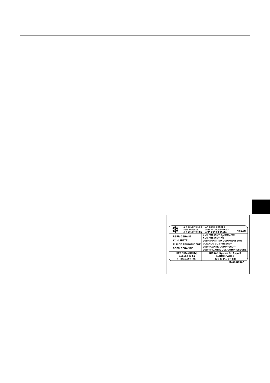
IDENTIFICATION LABEL FOR VEHICLE
Vehicles with factory installed fluorescent dye have this identification
label on the front side of hood.
MJIB0432E
ATC-12
PREPARATION
PREPARATION
PFP:00002
HFC-134a (R-134a) Service Tools and Equipment
BJS000AS
Never mix HFC-134a (R-134a) refrigerant and/or its specified lubricant with CFC-12 (R-12) refrigerant and/or
its lubricant.
Separate and non-interchangeable service equipment must be used for handling each type of refrigerant/lubri-
cant.
Refrigerant container fittings, service hose fittings and service equipment fittings (equipment which handles
refrigerant and/or lubricant) are different between CFC-12 (R-12) and HFC-134a (R-134a). This is to avoid
mixed use of the refrigerants/lubricant.
Adapters that convert one size fitting to another must never be used: refrigerant/lubricant contamination will
occur and compressor malfunction will result.
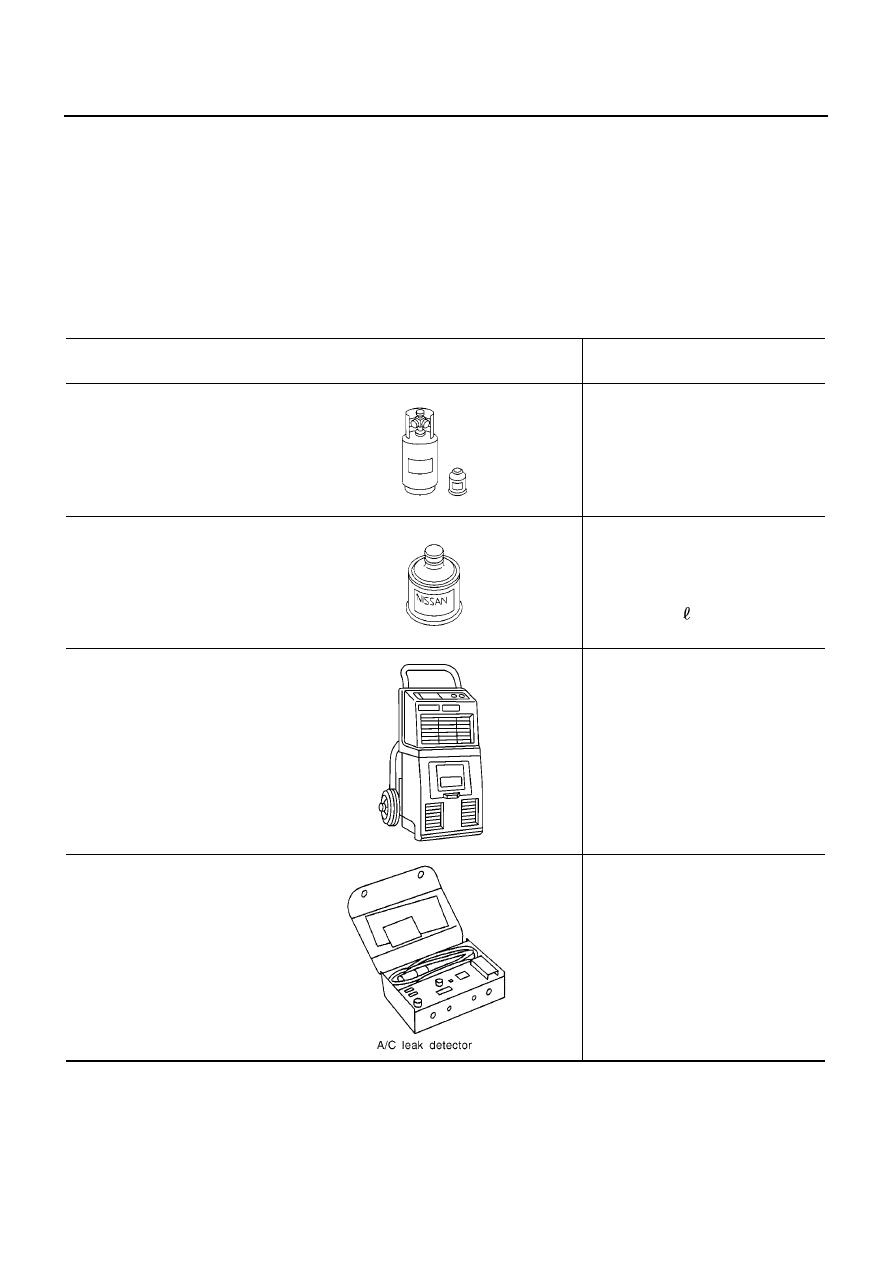
Tool number
Tool name
Description
HFC-134a (R-134a) refrigerant
Container color: Light blue
Container marking: HFC-134a (R-
134a)
Fitting size: Thread size
●
Large container 1/2
″
-16 ACME
KLH00-PAGR0
Nissan A/C System Oil Type R
(DH-PR)
Type: Polyalkylene glycol oil (PAG),
type R (DH-PR)
Application: HFC-134a (R-134a) vane
rotary compressors (Nissan only)
Lubricity: 40 m
(1.4 Imp fl oz.)
Recovery/Recycling/
Recharging equipment (ACR4)
Function: Refrigerant recovery and
recycling and recharging
Electrical leak detector
Power supply:
DC 12V (Cigarette lighter)
S-NT196
S-NT197
RJIA0195E
SHA705EB
PREPARATION
ATC-13
C
D
E
F
G
H
I
K
L
M
A
B
ATC
(J-43926)
Refrigerant dye leak detection kit
Kit includes:
(J-42220)
UV lamp and UV safety goggles
(J-41459)
HFC-134a (R-134a) dye injector
Use with J-41447, 1/4 ounce
bottle
(J-41447)
HFC-134a (R-134a) fluorescent
leak detection dye
(Box of 24, 1/4 ounce bottles)
(J-43872)
Refrigerant dye cleaner
Power supply:
DC 12V (Battery terminal)
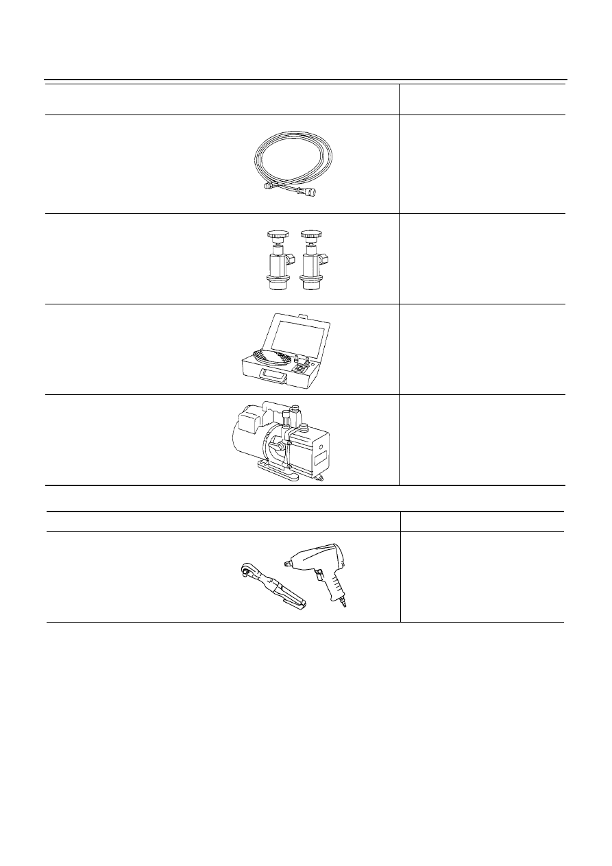
(J-42220)
UV lamp and UV safety goggles
Power supply:
DC 12V (Battery terminal)
For checking refrigerant leak when
fluorescent dye is installed in A/C
system
Includes:
UV lamp and UV safety goggles
(J-41447)
HFC-134a (R-134a) fluorescent
leak detection dye
(Box of 24, 1/4 ounce bottles)
Application:
For HFC-134a (R-134a) PAG oil
Container:
1/4 ounce (7.4 cc) bottle
(Includes self-adhesive dye
identification labels for affixing to
vehicle after charging system with
dye.)
(J-41459)
HFC-134a (R-134a) dye injector
Use with J-41447, 1/4 ounce
bottle
For injecting 1/4 ounce of fluorescent
leak detection dye into A/C system
(J-43872)
Refrigerant dye cleaner
For cleaning dye spills
Manifold gauge set (with hoses
and couplers)
Identification:
●
The gauge face indicates HFC-134a
(R-134a).
Fitting size: Thread size
●
1/2
″
-16 ACME
Tool number
Tool name
Description
ZHA200H
SHA438F
SHA439F
SHA440F
SHA441F
RJIA0196E
ATC-14
PREPARATION
Commercial Service Tools
BJS000AT
Service hoses
●
High-pressure side hose
●
Low-pressure side hose
●
Utility hose
Hose color:
●
Low hose: Blue with black stripe
●
High hose: Red with black stripe
●
Utility hose: Yellow with black stripe
or green with black stripe
Hose fitting to gauge:
●
1/2
″
-16 ACME
Service couplers
●
High-pressure side coupler
●
Low-pressure side coupler
Hose fitting to service hose:
●
M14 x 1.5 fitting is optional or
permanently attached.
Refrigerant weight scale
For measuring of refrigerant
Fitting size: Thread size
●
1/2
″
-16 ACME
Vacuum pump
(Including the isolator valve)
Capacity:
●
Air displacement: 4 CFM
●
Micron rating: 20 microns
●
Oil capacity: 482 g (17 oz.)
Fitting size: Thread size
●
1/2
″
-16 ACME
Tool number
Tool name
Description
S-NT201
S-NT202
S-NT200
S-NT203
Tool name
Description
Power tool
For loosening bolts and nuts
PBIC0190E
REFRIGERATION SYSTEM
ATC-15
C
D
E
F
G
H
I
K
L
M
A
B
ATC
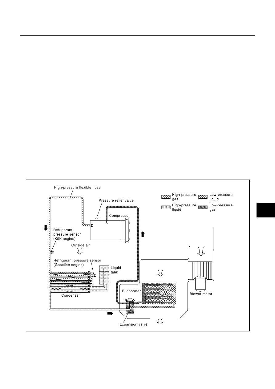
REFRIGERATION SYSTEM
PFP:KA990
Refrigerant Cycle
BJS000AU
REFRIGERANT FLOW
The refrigerant flows in the standard pattern, that is, through the compressor, the condenser with liquid tank,
through the evaporator, and back to the compressor. The refrigerant evaporation through the evaporator is
controlled by an externally equalized expansion valve, located inside the evaporator case.
FREEZE PROTECTION
Under usual operating conditions, when the A/C is switched ON, the compressor runs continuously, and the
evaporator pressure, and therefore, temperature is controlled by the compressor to prevent freeze up.
Refrigerant System Protection
BJS000AV
REFRIGERANT PRESSURE SENSOR
The refrigerant system is protected against excessively high- or low-pressures by the refrigerant pressure sen-
sor, located on the condenser. If the system pressure rises above, or falls below the specifications, the refrig-
erant pressure sensor detects the pressure inside the refrigerant line and sends the voltage signal to the ECM.
ECM makes the A/C relay go OFF and stops the compressor when pressure on the high-pressure side
detected by refrigerant pressure sensor is over about 2,746 kPa (27.46 bar, 28.0 kg/cm
2
, 398 psi), or below
about 134 kPa (1.34 bar, 1.4 kg/cm
2
, 20 psi).
PRESSURE RELIEF VALVE
The refrigerant system is also protected by a pressure relief valve, located in the rear head of the compressor.
When the pressure of refrigerant in the system increases to an unusual level [more than 3.8MPa (38 bar,
38.76 kg/cm
2
, 551 psi)], the release port on the pressure relief valve automatically opens and releases refrig-
erant into the atmosphere.
MJIB0355E
ATC-16
REFRIGERATION SYSTEM
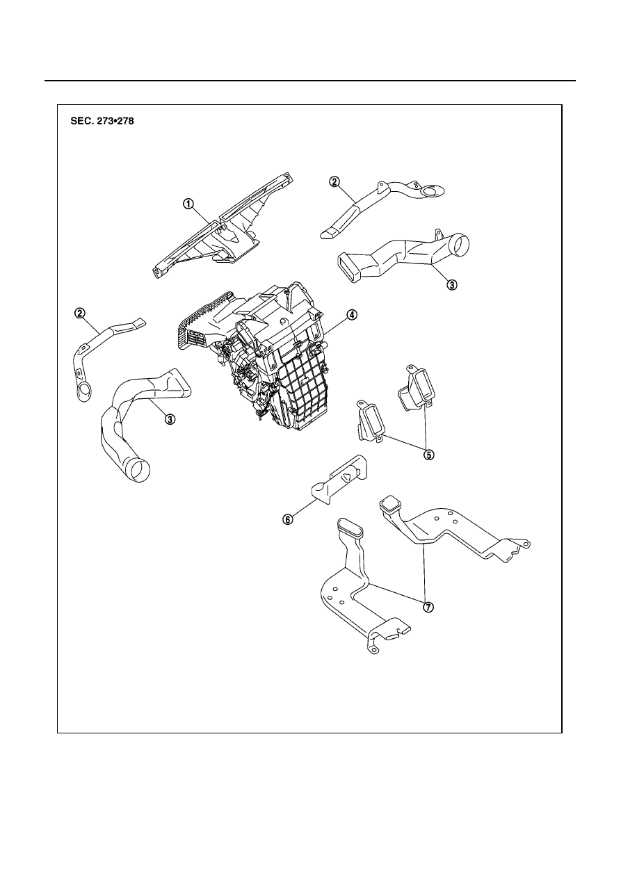
Component Layout
BJS000AW
1.
Defroster nozzle
2.
Side defroster duct
3.
Side ventilator duct
4.
A/C unit
5.
Center ventilator duct
6.
Front floor duct
7.
Rear floor duct
MJIB0368E

LUBRICANT
ATC-17
C
D
E
F
G
H
I
K
L
M
A
B
ATC
LUBRICANT
PFP:KLG00
Maintenance of Lubricant Quantity in Compressor
BJS000AX
The lubricant in the compressor circulates through the system with the refrigerant. Add lubricant to compres-
sor when replacing any component or after a large refrigerant leakage occurred. It is important to maintain the
specified amount.
If lubricant quantity is not maintained properly, the following malfunctions may result:
●
Lack of lubricant: May lead to a seized compressor.
●
Excessive lubricant: Inadequate cooling (thermal exchange interference)
LUBRICANT
LUBRICANT RETURN OPERATION
Adjust the lubricant quantity according to the test group shown below.
1.
CHECK LUBRICANT RETURN OPERATION
Can lubricant return operation be performed?
●
A/C system works properly.
●
There is no evidence of a large amount of lubricant leakage.
CAUTION:
If excessive lubricant leakage is noted, do not perform the lubricant return operation.
OK or NG
OK
>> GO TO 2.
NG
>> GO TO 3.
2.
PERFORM LUBRICANT RETURN OPERATION, PROCEEDING AS FOLLOWS
1.
Start engine, and set the following conditions:
–
Engine speed: Idling to 1,200 rpm
–
A/C switch: ON
–
Blower speed: Max. position
–
Temp. control: Optional (Set so that intake air temperature is 25 to 30
°
C.)
–
Intake position: Recirculation (REC)
2.
Perform lubricant return operation for about 10 minutes.
3.
Stop engine.
>> GO TO 3.
3.
CHECK REPLACEMENT PART
Should the compressor be replaced?
YES
>> GO TO
ATC-18, "LUBRICANT ADJUSTING PROCEDURE FOR COMPRESSOR REPLACE-
.
NO
>> GO TO
ATC-18, "LUBRICANT ADJUSTING PROCEDURE FOR COMPONENTS REPLACE-
.
Gasoline engine
K9K engine
Name
Nissan A/C System Oil Type R
Nissan A/C System Oil Type S
Parts number
KLH00 - PAGR0
KLH00 - PAGS0
ATC-18
LUBRICANT
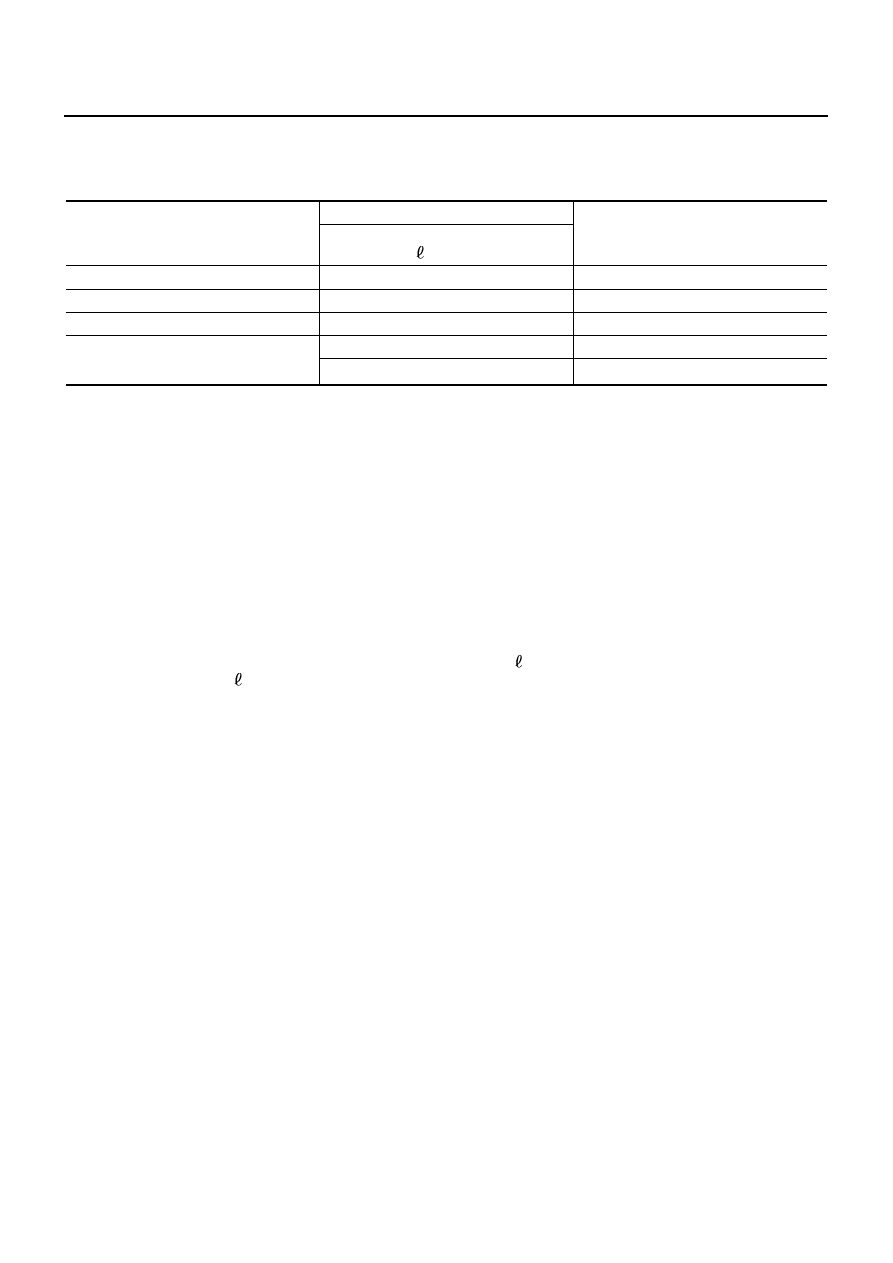
LUBRICANT ADJUSTING PROCEDURE FOR COMPONENTS REPLACEMENT EXCEPT COM-
PRESSOR
After replacing any of the following major components, add the correct amount of lubricant to the system.
Amount of lubricant to be added
*1: If refrigerant leak is small, no addition of lubricant is needed.
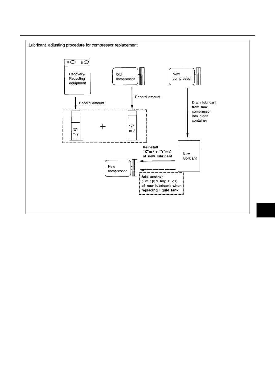
LUBRICANT ADJUSTING PROCEDURE FOR COMPRESSOR REPLACEMENT
1.
Before connecting ACR4 to vehicle, check ACR4 gauges. No refrigerant pressure should be displayed. If
NG, recover refrigerant from equipment lines.
2.
Discharge refrigerant into the refrigerant recovery/recycling equipment. Measure lubricant discharged into
the recovery/recycling equipment.
3.
Drain the lubricant from the old (removed) compressor into a graduated container and recover the amount
of lubricant drained.
4.
Drain the lubricant from the new compressor into a separate, clean container.
5.
Measure an amount of new lubricant installed equal to amount drained from old compressor. Add this
lubricant to new compressor through the suction port opening.
6.
Measure an amount of new lubricant equal to the amount recovered during discharging. Add this lubricant
to new compressor through the suction port opening.
7.
If the liquid tank also needs to be replaced, add another 5 m
(0.2 Imp fl oz.) of lubricant at this time.
Do not add this 5 m
(0.2 Imp fl oz.) of lubricant only when replaces the compressor.
Part replaced
Lubricant to be added to system
Remarks
Amount of lubricant
m
(Imp fl oz.)
Evaporator
35 (1.2)
-
Condenser
15 (0.5)
-
Liquid tank
5 (0.2)
-
In case of refrigerant leak
30 (1.1)
Large leak
-
Small leak
*1
LUBRICANT
ATC-19
C
D
E
F
G
H
I
K
L
M
A
B
ATC
SJIA0596E

ATC-20
AIR CONDITIONER CONTROL
AIR CONDITIONER CONTROL
PFP:27500
System Construction
BJS000AY
AIR MIX DOOR CONTROL (AUTOMATIC TEMPERATURE CONTROL)
The air mix door is automatically controlled so that in-vehicle temperature is maintained at a predetermined
value by the temperature setting, ambient temperature, in-vehicle temperature and amount of sunload.
FAN SPEED CONTROL
Blower speed is automatically controlled by the temperature setting, ambient temperature, in-vehicle tempera-
ture, intake temperature, amount of sunload and air mix door position.
With fan control dial set to AUTO switch is pressed, the blower motor starts to gradually increase air flow vol-
ume.
When engine coolant temperature is low, the blower motor operation is delayed to prevent cool air from flow-
ing.
INTAKE DOOR CONTROL
The intake doors are automatically controlled by the temperature setting, ambient temperature, in-vehicle tem-
perature, intake temperature, amount of sunload and ON-OFF operation of the compressor.
OUTLET DOOR CONTROL
The outlet door is automatically controlled by the temperature setting, ambient temperature, in-vehicle temper-
ature, intake temperature and amount of sunload.
AIR CONDITIONER CONTROL
ATC-21
C
D
E
F
G
H
I
K
L
M
A
B
ATC
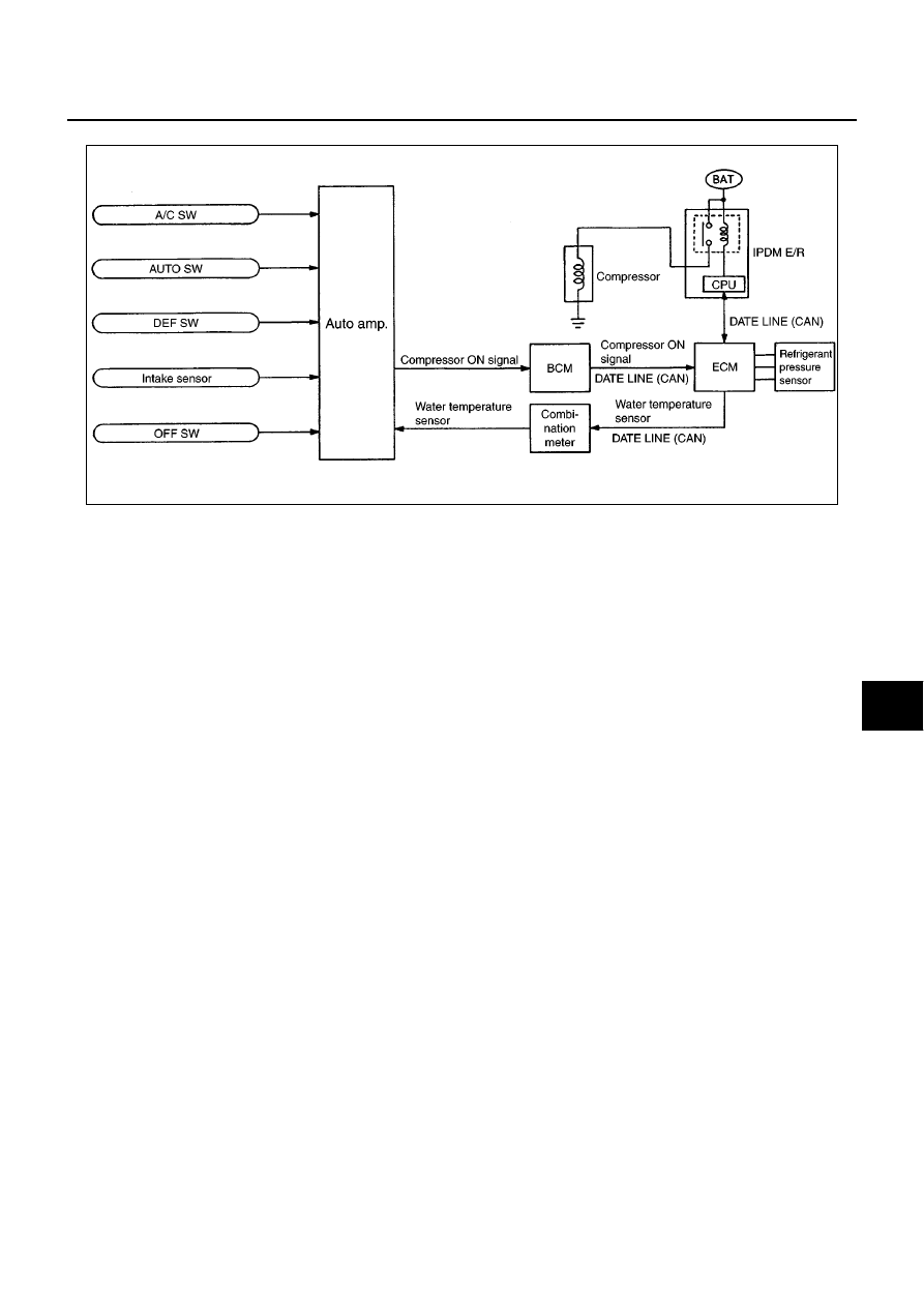
MAGNET CLUTCH CONTROL
When A/C switch, AUTO switch or DEF switch is pressed, auto amp. inputs compressor ON signal to BCM.
BCM sends compressor ON signal to ECM, via CAN communication line.
ECM judges whether compressor can be turned ON, based on each sensor status (refrigerant-pressure sen-
sor signal, throttle angle, etc.). If it judges compressor can be turned ON, it sends compressor ON signal to
IPDM E/R, via CAN communication line.
Upon receipt of compressor ON signal from ECM, IPDM E/R turns air conditioner relay ON to operate com-
pressor.
SELF-DIAGNOSTIC SYSTEM
The self-diagnostic system is built into the auto amp. to quickly locate the cause of symptoms.
SJIA0703E
ATC-22
AIR CONDITIONER CONTROL
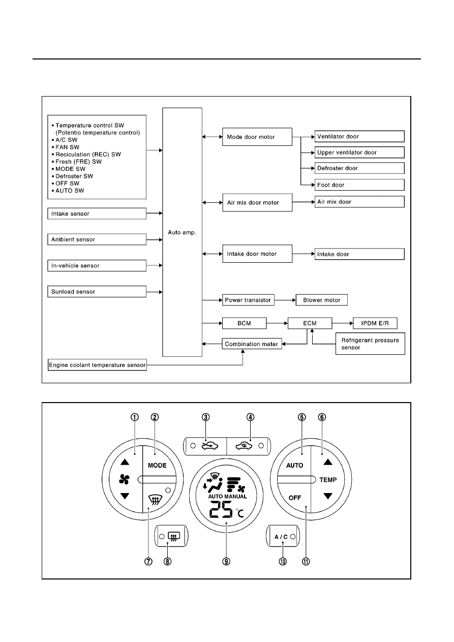
Description of Control System
BJS000AZ
The control system consists of input sensors, switches, the auto amp. (microcomputer) and outputs.
The relationship of these components is shown in the figure below:
Control Operation
BJS000B0
SJIA0712E
1.
Fan SW
2.
MODE SW
3.
Fresh (FRE) SW
4.
Reciculation (REC) SW
5.
AUTO SW
6.
Temperature control SW
MJIB0369E

AIR CONDITIONER CONTROL
ATC-23
C
D
E
F
G
H
I
K
L
M
A
B
ATC
DISPLAY SCREEN
Displays the operational status of the system.
AUTO SWITCH
●
The compressor, intake doors, air mix doors, outlet doors and blower speed are automatically controlled
so that the in-vehicle temperature will reach, and be maintained at the set temperature selected by the
operator.
●
When pressing AUTO switch, air inlet, air outlet, fan speed, and discharge air temperature are automati-
cally controlled. (Inlet is automatically controlled only when FRE or REC switch is OFF.)
TEMPERATURE CONTROL SWITCH (POTENTIO TEMPERATURE CONTROL)
Increases or decreases the set temperature.
RECIRCULATION (REC) SWITCH
●
When REC switch is ON, REC switch indicator turns ON, air inlet is fixed to REC, and compressor will turn
ON.
●
When FRE switch is turned ON, air outlet switches to D/F or DEF position, or when compressor is turned
from ON to OFF, REC switch is automatically turned OFF (fixed to FRE mode).
FRESH (FRE) SWITCH
●
When FRE switch is ON, FRE switch indicator turns ON, and air inlet is fixed to FRE.
●
When REC switch is turned ON, FRE switch is automatically turned OFF (fixed to REC mode). FRE mode
can be re-entered by pressing FRE switch again.
DEFROSTER (DEF) SWITCH
Positions the air outlet doors to the defrost position. Also positions the intake doors to the outside air position,
and compressor will turn ON.
REAR WINDOW DEFOGGER SWITCH
When illumination is ON, rear window is defogged.
OFF SWITCH
The compressor and blower are OFF, the intake doors are set to the outside air position, and the air outlet
doors are set to the foot position.
A/C SWITCH
The compressor is ON or OFF.
(Pressing the A/C switch when the A/C switch is ON will turn off the A/C switch and compressor.)
MODE SWITCH
Controls the air discharge outlets.
When air outlet switches to D/F position, compressor will turn ON and fixed to REC mode.
FAN SWITCH
Manually control the blower speed. Four speeds are available for manual control (as shown on the display
screen).
7.
Defroster (DEF) SW
8.
Rear window defogger SW
9.
Display screen
10. A/C SW
11.
OFF SW
ATC-24
AIR CONDITIONER CONTROL
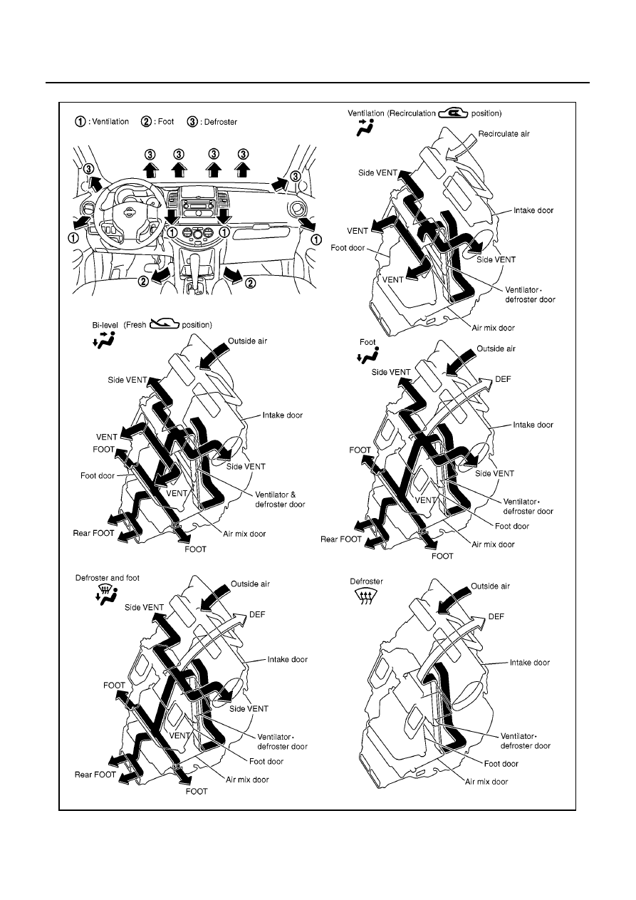
Discharge Air Flow
BJS000JB
MJIB0511E
AIR CONDITIONER CONTROL
ATC-25
C
D
E
F
G
H
I
K
L
M
A
B
ATC
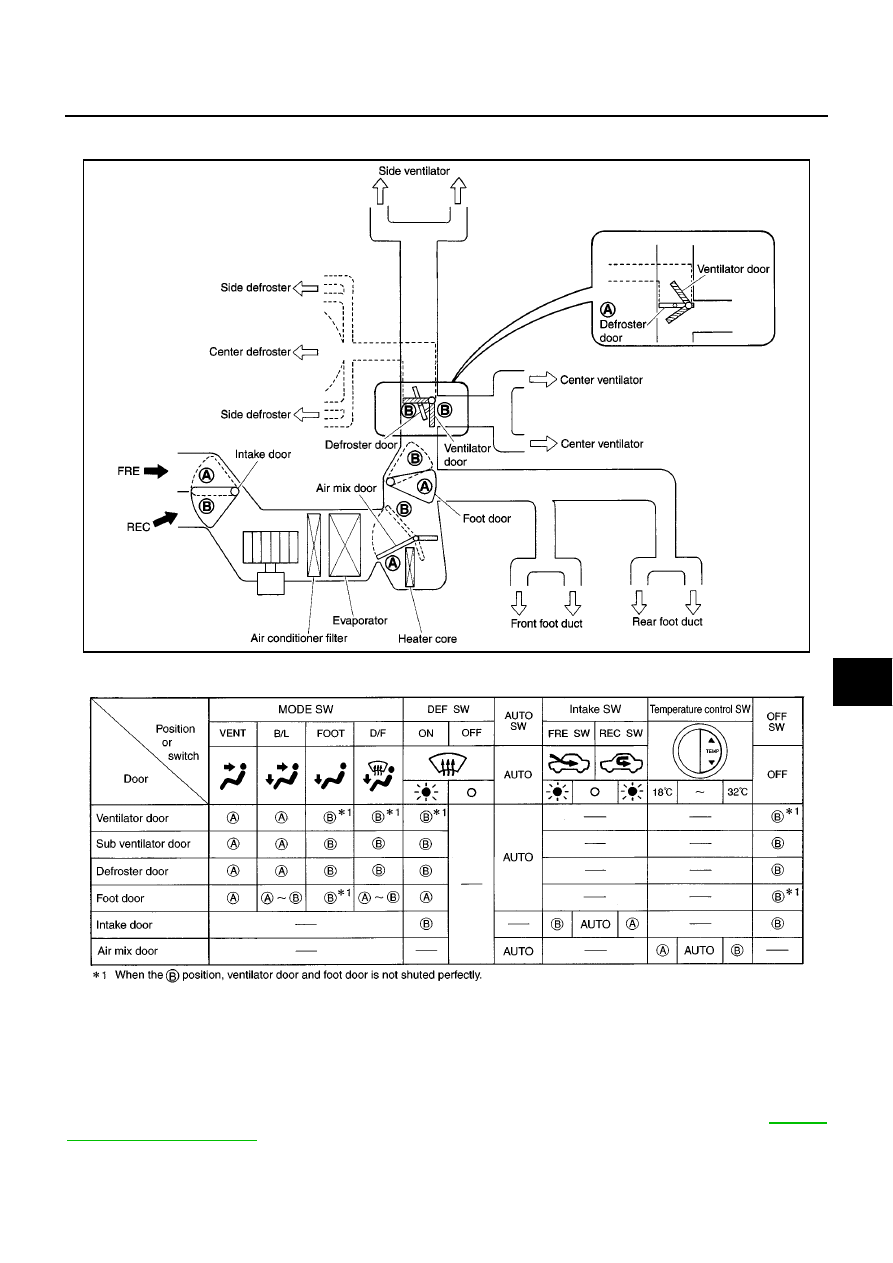
System Description
BJS000B4
SWITCHES AND THEIR CONTROL FUNCTION
CAN Communication System Description
BJS000B5
CAN (Controller Area Network) is a serial communication line for real time application. It is an on-vehicle mul-
tiplex communication line with high data communication speed and excellent error detection ability. Many elec-
tronic control units are equipped onto a vehicle, and each control unit shares information and links with other
control units during operation (not independent). In CAN communication, control units are connected with 2
communication lines (CAN-H line, CAN-L line) allowing a high rate of information transmission with less wiring.
Each control unit transmits/receives data but selectively reads required data only. For details, refer to
.
MJIB0507E
SJIA0717E
ATC-26
TROUBLE DIAGNOSIS
TROUBLE DIAGNOSIS
PFP:00004
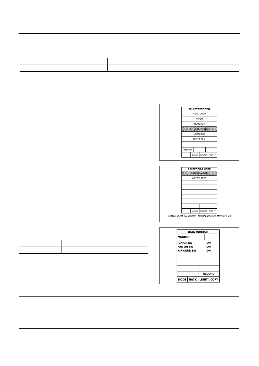
CONSULT-II Function (BCM)
BJS000B6
CONSULT-II can display diagnostic item using the diagnostic test modes shown following.
CONSULT-II BASIC OPERATION
Refer to
GI-36, "CONSULT-II Start Procedure"
.
DATA MONITOR
Operation Procedure
1.
Touch “AIR CONDITIONER” on “SELECT TEST ITEM” screen.
2.
Touch “DATA MONITOR” on “SELECT DIAG MODE” screen.
3.
Touch either “ALL SIGNALS” or “SELECTION FROM MENU” on
“DATA MONITOR” screen.
4.
When “SELECTION FROM MENU” is selected, touch items to
be monitored. When “ALL SIGNALS” is selected, all the items
will be monitored.
5.
Touch “START”.
6.
Touch “RECORD” while monitoring, then the status of the moni-
tored item can be recorded. To stop recording, touch “STOP”.
Display Item List
System part
Check item, diagnosis mode
Description
BCM
Data monitor
Displays BCM input data in real time.
MJIB0465E
MJIB0466E
All signals
Monitors all the items.
Selection from menu
Selects and monitors the individual item selected.
RJIA1111E
Monitor item name
“operation or unit”
Contents
IGN ON SW
“ON/OFF”
Displays “IGN Position (ON)/OFF, ACC Position (OFF)” status as judged from ignition switch signal.
FAN ON SIG
“ON/OFF”
Displays “FAN (ON)/FAN (OFF)” status as judged from blower fan motor switch signal.
AIR COND SW
“ON/OFF”
Displays “COMP (ON)/COMP (OFF)” status as judged from air conditioner switch signal.
TROUBLE DIAGNOSIS
ATC-27
C
D
E
F
G
H
I
K
L
M
A
B
ATC
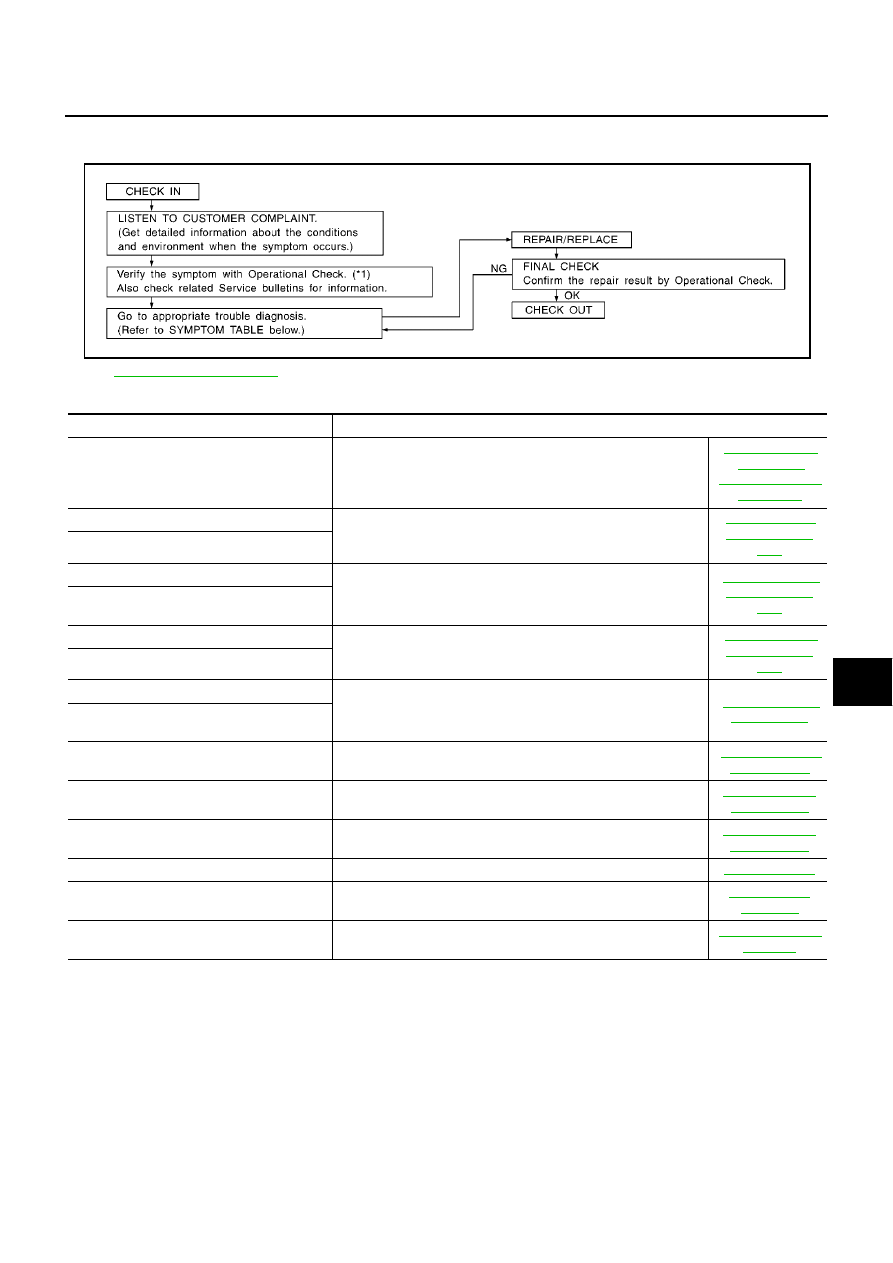
How to Perform Trouble Diagnosis for Quick and Accurate Repair
BJS000B7
WORK FLOW
SYMPTOM TABLE
*1
SHA900E
Symptom
Reference Page
A/C system does not come on.
Go to Trouble Diagnosis Procedure for A/C System.
Air outlet does not change.
Go to Trouble Diagnosis Procedure for Mode Door Motor.
Mode door motor does not operate normally.
Discharge air temperature does not change.
Go to Trouble Diagnosis Procedure for Air Mix Door Motor.
Air mix door motor does not operate nor-
mally.
Intake door does not change.
Go to Trouble Diagnosis Procedure for Intake Door Motor.
Intake door motor does not operate normally.
Blower motor operation is malfunctioning.
Go to Trouble Diagnosis Procedure for Blower Motor.
Blower motor operation is malfunctioning
under out of starting fan speed control.
Magnet clutch does not engage.
Go to Trouble Diagnosis Procedure for Magnet Clutch.
Insufficient cooling
Go to Trouble Diagnosis Procedure for Insufficient Cooling.
Insufficient heating
Go to Trouble Diagnosis Procedure for Insufficient Heating.
Noise
Go to Trouble Diagnosis Procedure for Noise.
Self-diagnosis cannot be performed.
Go to Trouble Diagnosis Procedure for Self-diagnosis.
Memory function does not operate.
Go to Trouble Diagnosis Procedure for Memory Function.
ATC-28
TROUBLE DIAGNOSIS
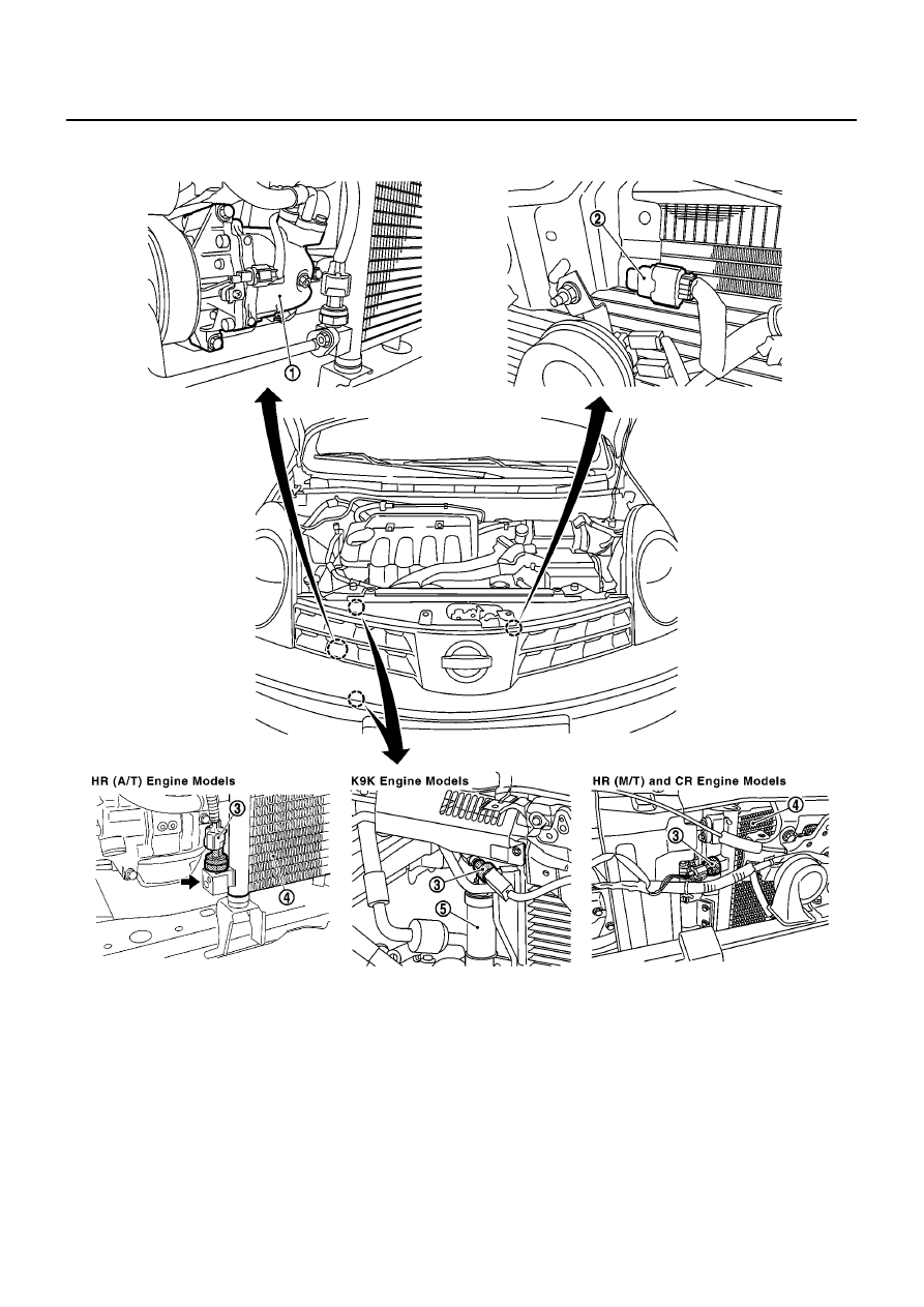
Component Parts and Harness Connector Location
BJS000B8
ENGINE COMPARTMENT
1.
Compressor
(CR & HR engine F28)
(K9K engine F129)
2.
Ambient sensor E17
3.
Refrigerant pressure sensor
(CR & HR engine E21)
(K9K engine E65)
4.
Condenser
5.
Liquid tank
MJIB0478E
TROUBLE DIAGNOSIS
ATC-29
C
D
E
F
G
H
I
K
L
M
A
B
ATC
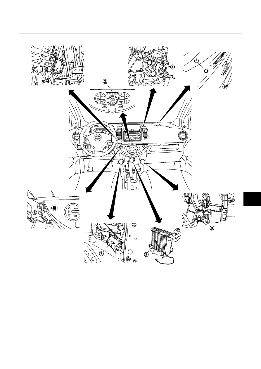
PASSENGER COMPARTMENT
1.
Power transistor M30, M31
2.
Intake door motor M28
3.
Controller (Auto amp.) M64, M65
4.
Blower motor M56
5.
Sunload sensor M43
6.
In-vehicle sensor M43
7.
Air mix door motor M51
8.
Intake sensor M44
9.
Mode door motor M50
MJIB0479E
ATC-30
TROUBLE DIAGNOSIS
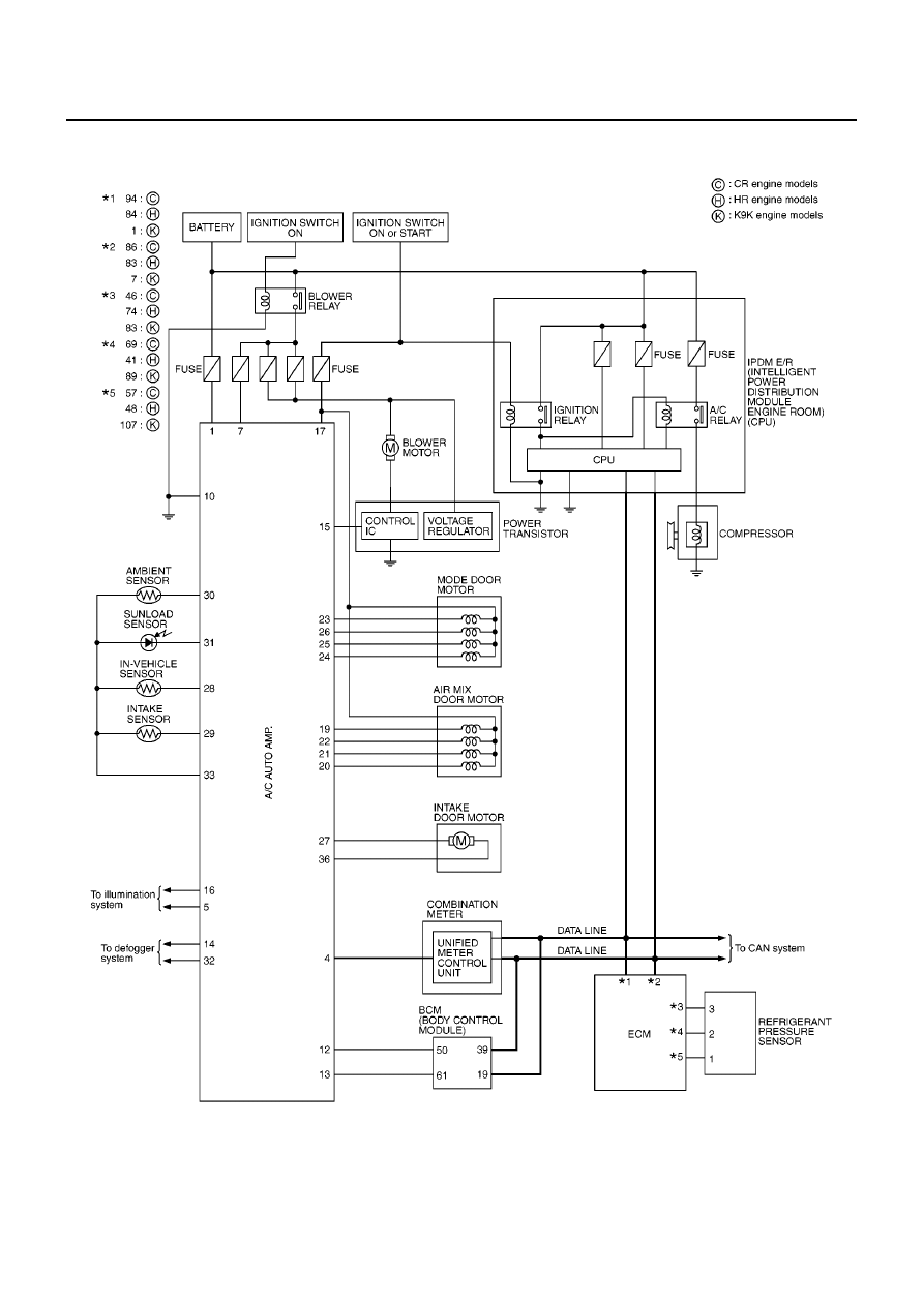
Circuit Diagram
BJS000B9
MJWA0273E
TROUBLE DIAGNOSIS
ATC-31
C
D
E
F
G
H
I
K
L
M
A
B
ATC
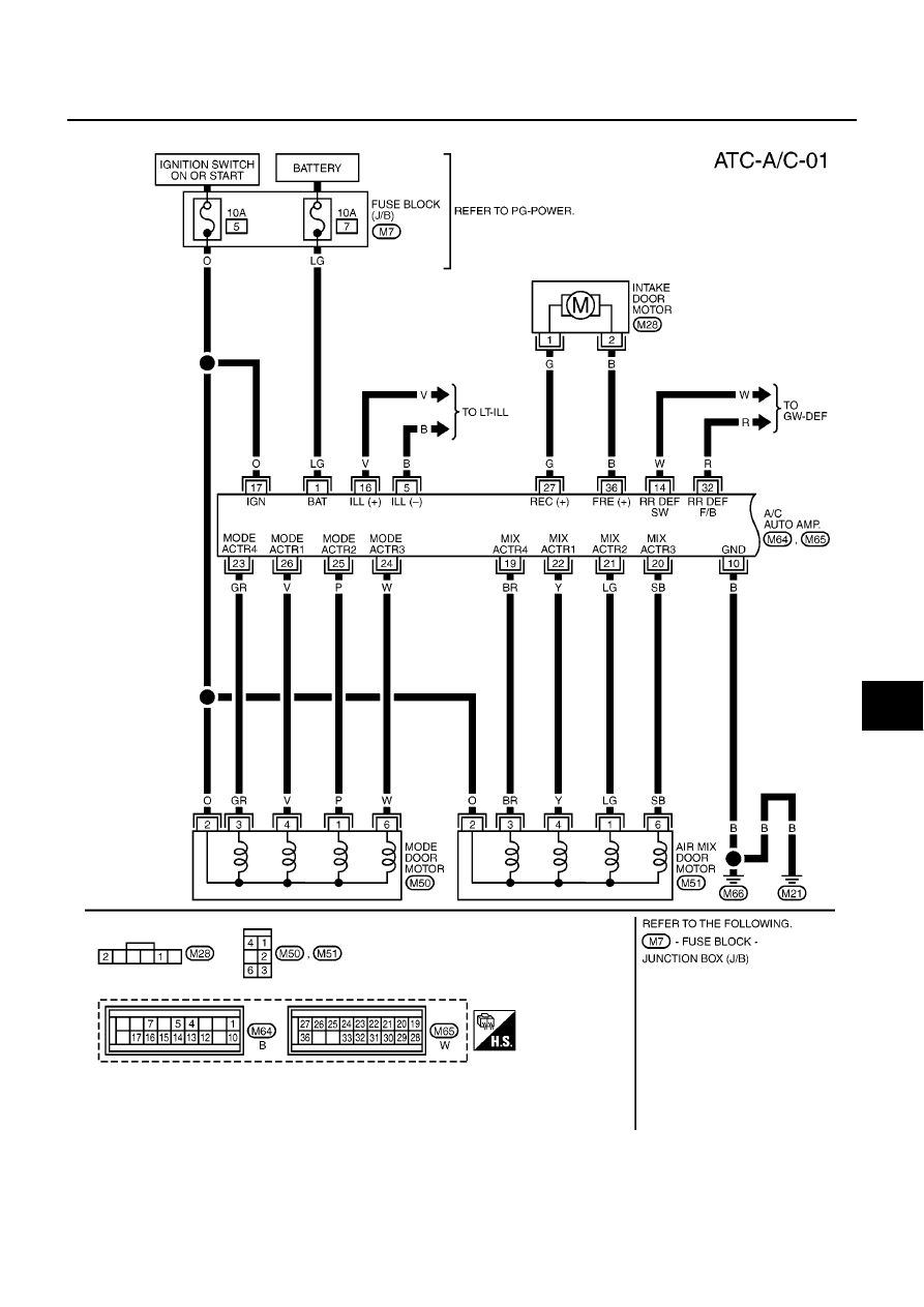
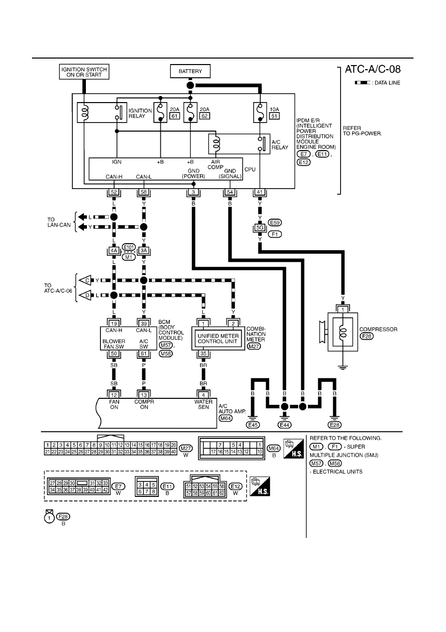
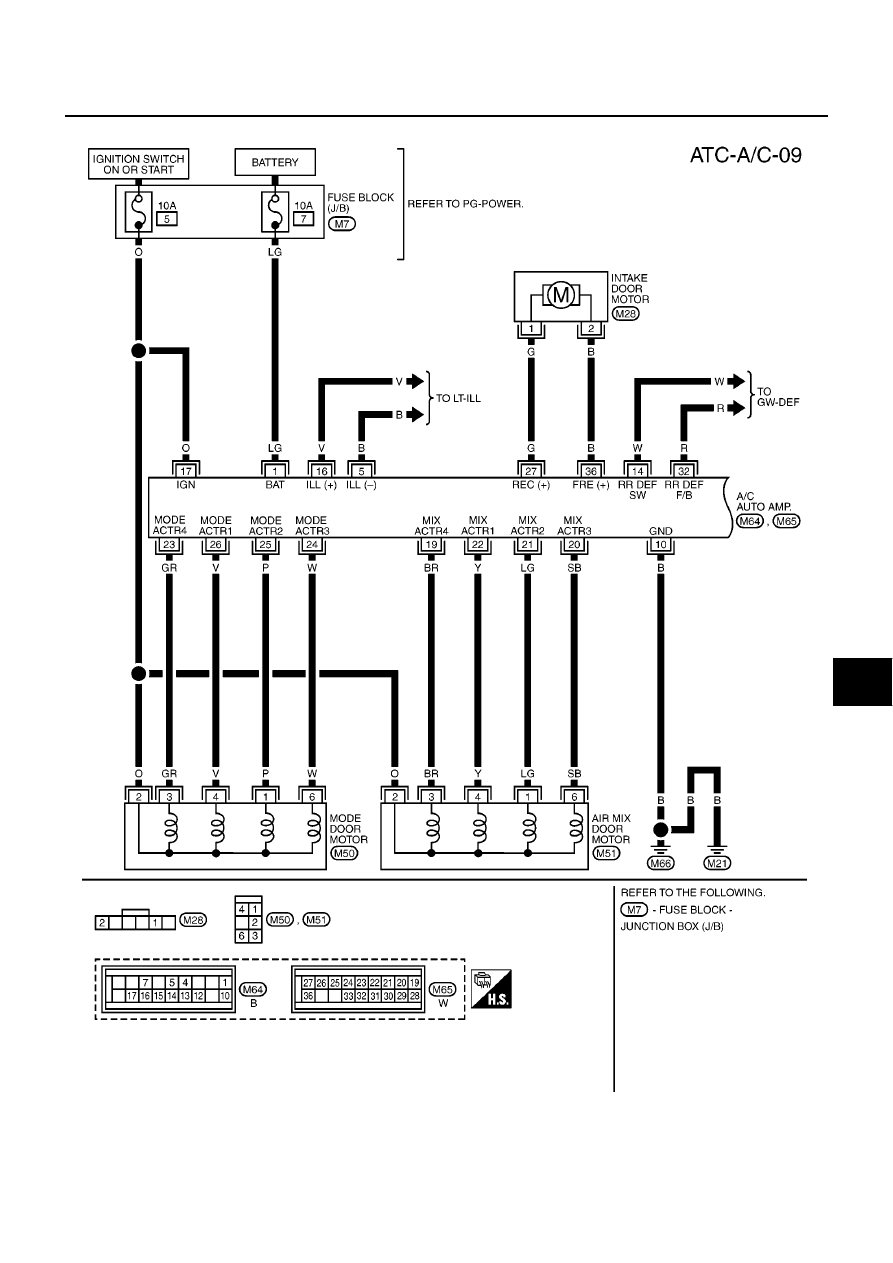
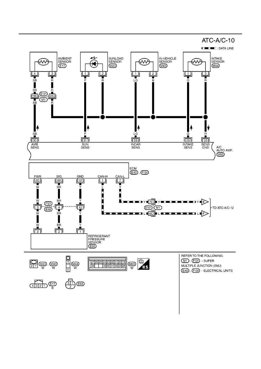
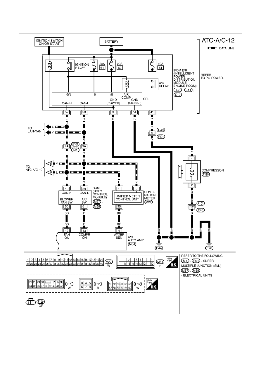
Wiring Diagram —A/C— CR Engine Models
BJS000BA
MJWA0274E
ATC-32
TROUBLE DIAGNOSIS
MJWA0275E
TROUBLE DIAGNOSIS
ATC-33
C
D
E
F
G
H
I
K
L
M
A
B
ATC
MJWA0276E
ATC-34
TROUBLE DIAGNOSIS
MJWA0277E

TROUBLE DIAGNOSIS
ATC-35
C
D
E
F
G
H
I
K
L
M
A
B
ATC
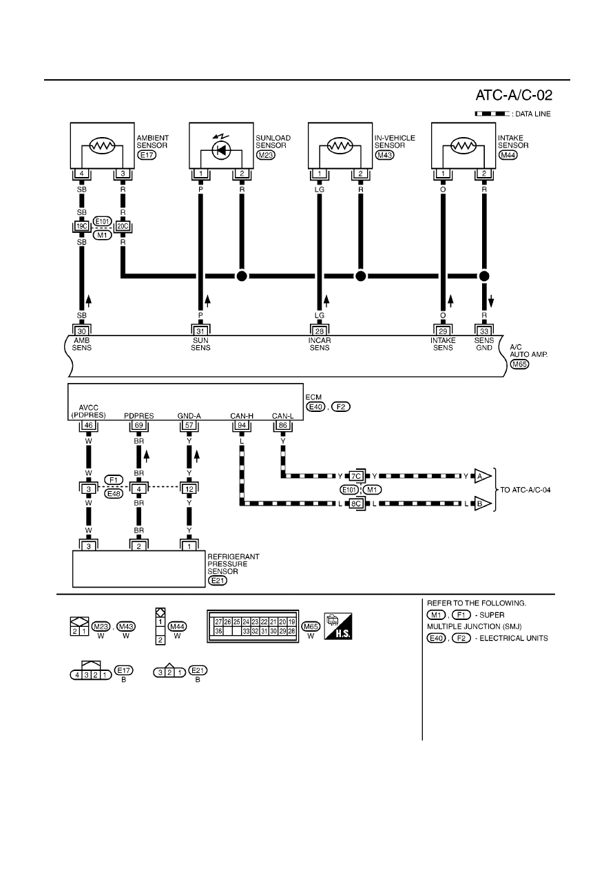
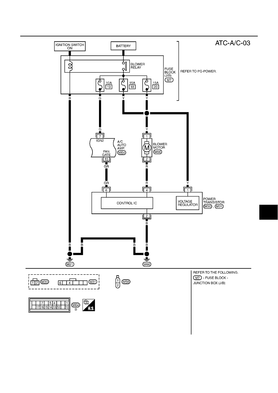
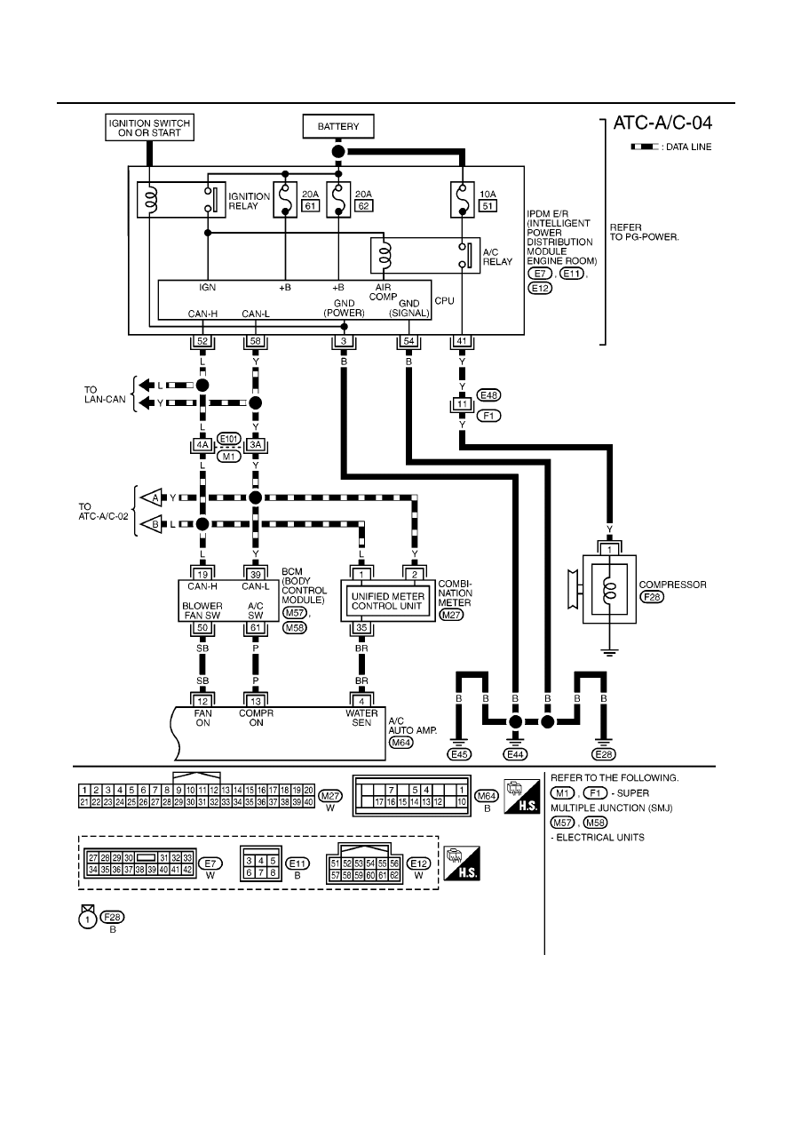
Wiring Diagram —A/C—HR Engine Models
BJS000JD
MJWA0278E
ATC-36
TROUBLE DIAGNOSIS
MJWA0279E

TROUBLE DIAGNOSIS
ATC-37
C
D
E
F
G
H
I
K
L
M
A
B
ATC
MJWA0280E
ATC-38
TROUBLE DIAGNOSIS
MJWA0281E
TROUBLE DIAGNOSIS
ATC-39
C
D
E
F
G
H
I
K
L
M
A
B
ATC
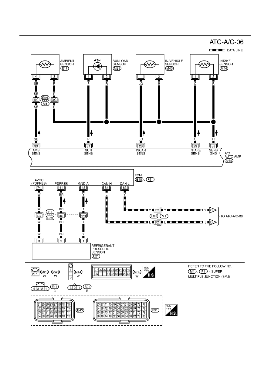
Wiring Diagram —A/C— K9K Engine Models
BJS000EZ
MJWA0282E
ATC-40
TROUBLE DIAGNOSIS
MJWA0283E

TROUBLE DIAGNOSIS
ATC-41
C
D
E
F
G
H
I
K
L
M
A
B
ATC
MJWA0284E
ATC-42
TROUBLE DIAGNOSIS
MJWA0285E
TROUBLE DIAGNOSIS
ATC-43
C
D
E
F
G
H
I
K
L
M
A
B
ATC
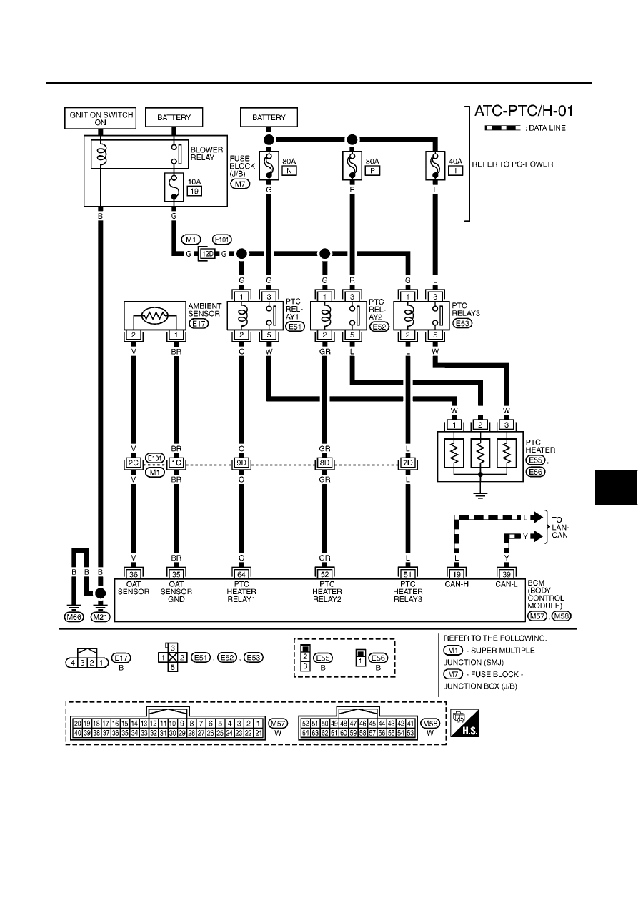
Wiring Diagram —PTC/H— K9K Engine LHD Models
BJS000F0
PTC heater function is intended to improve the heating performance with CTP electrical system for air heating
system which is broken down into several stages controlled by relays.
MJWA0286E
ATC-44
TROUBLE DIAGNOSIS
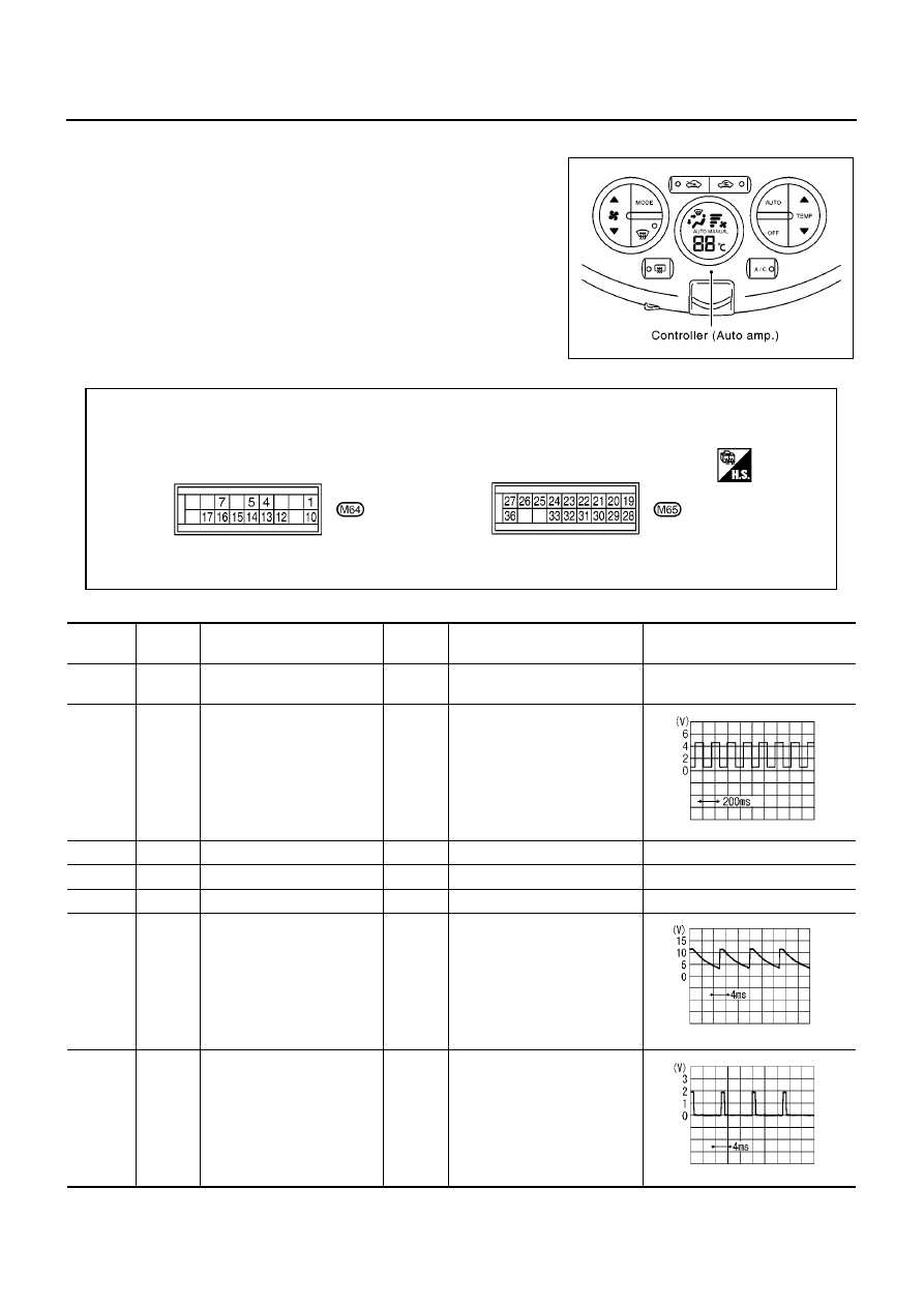
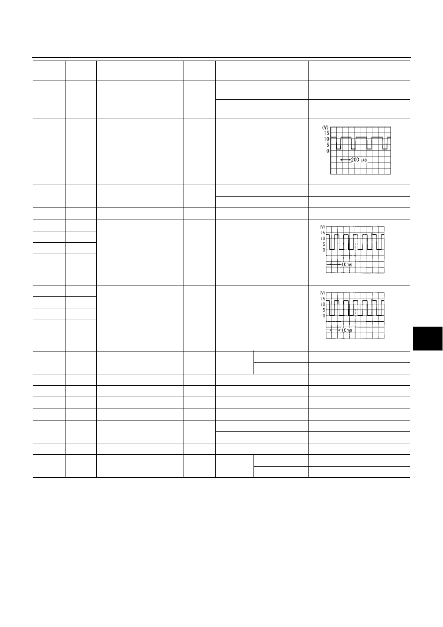
Auto Amp. Terminals and Reference Value
BJS000BB
Measure voltage between each terminal and ground by following ter-
minals and reference value for auto amp.
PIN CONNECTOR TERMINAL LAYOUT
TERMINALS AND REFERENCE VALUE FOR AUTO AMP.
MJIB0370E
MJIB0371E
Terminal
No.
Wire
color
Item
Ignition
switch
Condition
Voltage
(V)
1
LG
Power supply for BAT
OFF
-
Battery voltage
4
BR
Engine coolant temperature
sensor signal
ON
At idle (after warming up,
approx. 80
°
C)
CAUTION:
The wave forms vary
depending on coolant tem-
perature.
5
B
Illumination ground
ON
-
Approx. 0
7
G
Power supply for IGN 2
OFF
-
Battery voltage
10
B
Ground
ON
-
Approx. 0
12
SB
FAN ON signal
ON
FAN speed: 1st step (manual)
13
P
Compressor ON signal
ON
A/C switch: ON
(Blower motor operates.)
SKIB3651J
ZJIA0583J
ZJIA0584J
TROUBLE DIAGNOSIS
ATC-45
C
D
E
F
G
H
I
K
L
M
A
B
ATC
14
W
Rear window defogger ON
signal
ON
When rear window defogger
switch is depressed.
Approx. 0
When rear window defogger
switch is released.
Approx. 5
15
GR
Blower PWM
ON
FAN speed: 1st step (manual)
16
V
Illumination signal
ON
Light switch: ON
Approx. 12
Light switch: OFF
Approx. 0
17
O
Power supply for IGN 1
ON
-
Battery voltage
19
BR
Air mix door motor drive sig-
nal
ON
Immediately after temperature
adjustment switch operation
20
SB
21
LG
22
Y
23
GR
Mode door motor drive signal
ON
Immediately after mode switch
operation
24
W
25
P
26
V
27
G
Intake door motor drive sig-
nal
ON
REC or
FRE switch
REC
→
FRE
Approx. 0
FRE
→
REC
Approx. 12
28
LG
In-vehicle sensor
-
-
-
29
O
Intake sensor
-
-
-
30
SB
Ambient sensor
-
-
-
31
P
Sunload sensor
-
-
-
32
R
Rear window defogger feed-
back signal
ON
Rear window defogger: ON
Approx. 12
Rear window defogger: OFF
Approx. 0
33
R
Sensor ground
ON
-
Approx. 0
36
B
Intake door motor drive sig-
nal
ON
REC or
FRE switch
REC
→
FRE
Approx. 12
FRE
→
REC
Approx. 0
Terminal
No.
Wire
color
Item
Ignition
switch
Condition
Voltage
(V)
ZJIA0863J
HAK0627D
HAK0627D

ATC-46
TROUBLE DIAGNOSIS
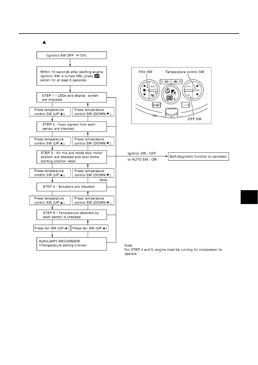
Self-diagnosis Function
BJS000BC
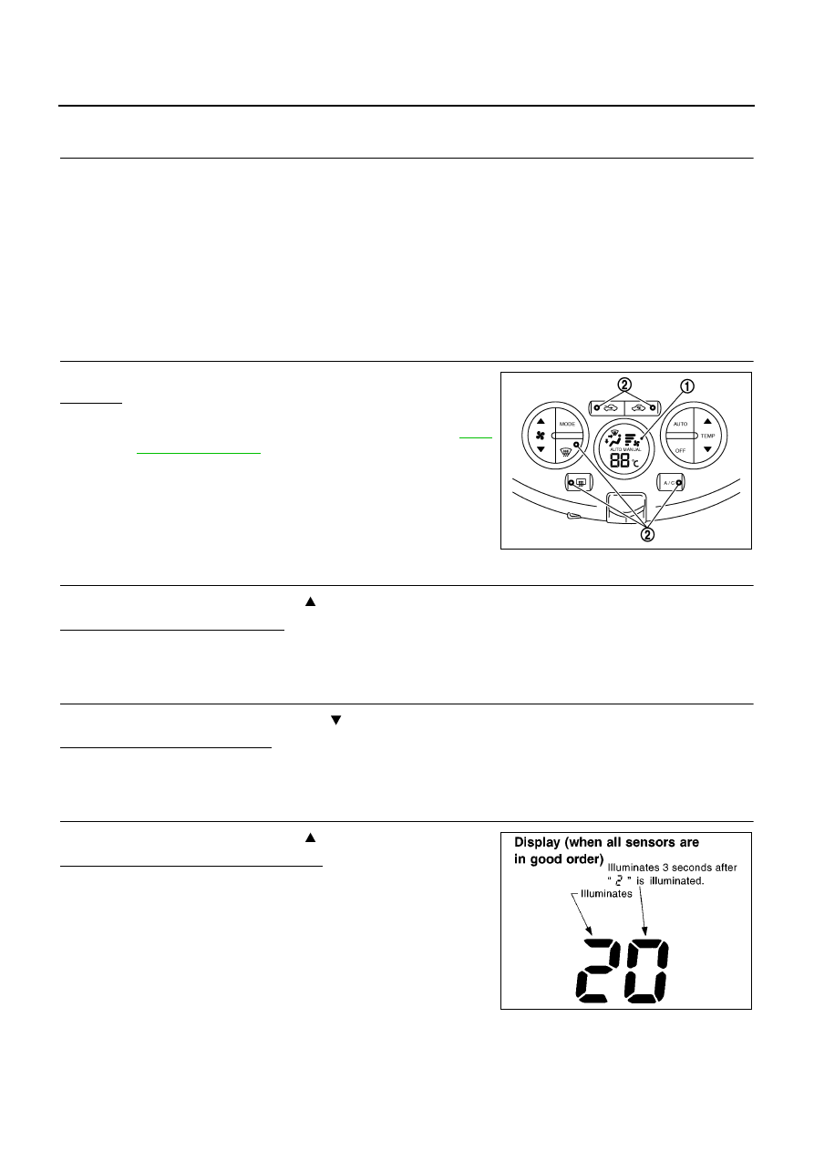
DESCRIPTION
The self-diagnostic system diagnoses sensors, door motors, blower motor, etc. by system line. Refer to appli-
cable sections (items) for details. Shifting from usual control to the self-diagnostic system is accomplished by
starting the engine (turning the ignition switch ON) and pressing OFF switch for at least 5 seconds. The OFF
switch must be pressed within 10 seconds after starting the engine (ignition switch is turned ON). This system
will be canceled by either pressing AUTO switch or turning the ignition switch OFF. Shifting from one step to
another is accomplished by means of pushing temperature control switch, as required.
TROUBLE DIAGNOSIS
ATC-47
C
D
E
F
G
H
I
K
L
M
A
B
ATC
Additionally shifting from STEP-5 to AUXILIARY MECHANISM is accomplished by means of pushing fan
switch (UP: ).
MJIB0372E
ATC-48
TROUBLE DIAGNOSIS
FUNCTION CONFIRMATION PROCEDURE
1.
SET IN SELF-DIAGNOSTIC MODE
1.
Turn ignition switch ON.
2.
Set in self-diagnostic mode as follows. Within 10 seconds after starting engine (ignition switch is turned
ON.), press OFF switch for at least 5 seconds.
CAUTION:
If battery voltage drops below 12V during diagnosis STEP-3, door motor speed becomes slower and
as a result, the system may generate an error even when operation is usual. To avoid this, start engine
before performing this diagnosis.
>> GO TO 2.
2.
STEP-1: LED AND DISPLAY ARE CHECKED
Check display screen (1) and LED illumination (2).
OK or NG
OK
>> GO TO 3.
NG
>> Malfunction OFF switch or AUTO amp. Refer to
.
3.
CHECK TO ADVANCE SELF-DIAGNOSIS STEP-2
Press temperature control switch (UP:
).
Advance to self-diagnosis STEP-2?
YES
>> GO TO 4.
NO
>> Replace auto amp. (Temperature control switch is malfunctioning.)
4.
CHECK TO RETURN SELF-DIAGNOSIS STEP-1
Press temperature control switch (DOWN:
).
Return to self-diagnosis STEP-1?
YES
>> GO TO 5.
NO
>> Replace auto amp. (Temperature control switch is malfunctioning.)
5.
STEP-2: SENSOR CIRCUITS ARE CHECKED FOR OPEN OR SHORT CIRCUIT
Press temperature control switch (UP:
).
Does code No. 20 appear on the display?
YES
>> GO TO 6.
NO
>> GO TO 13.
MJIB0373E
SJIA0737E
TROUBLE DIAGNOSIS
ATC-49
C
D
E
F
G
H
I
K
L
M
A
B
ATC
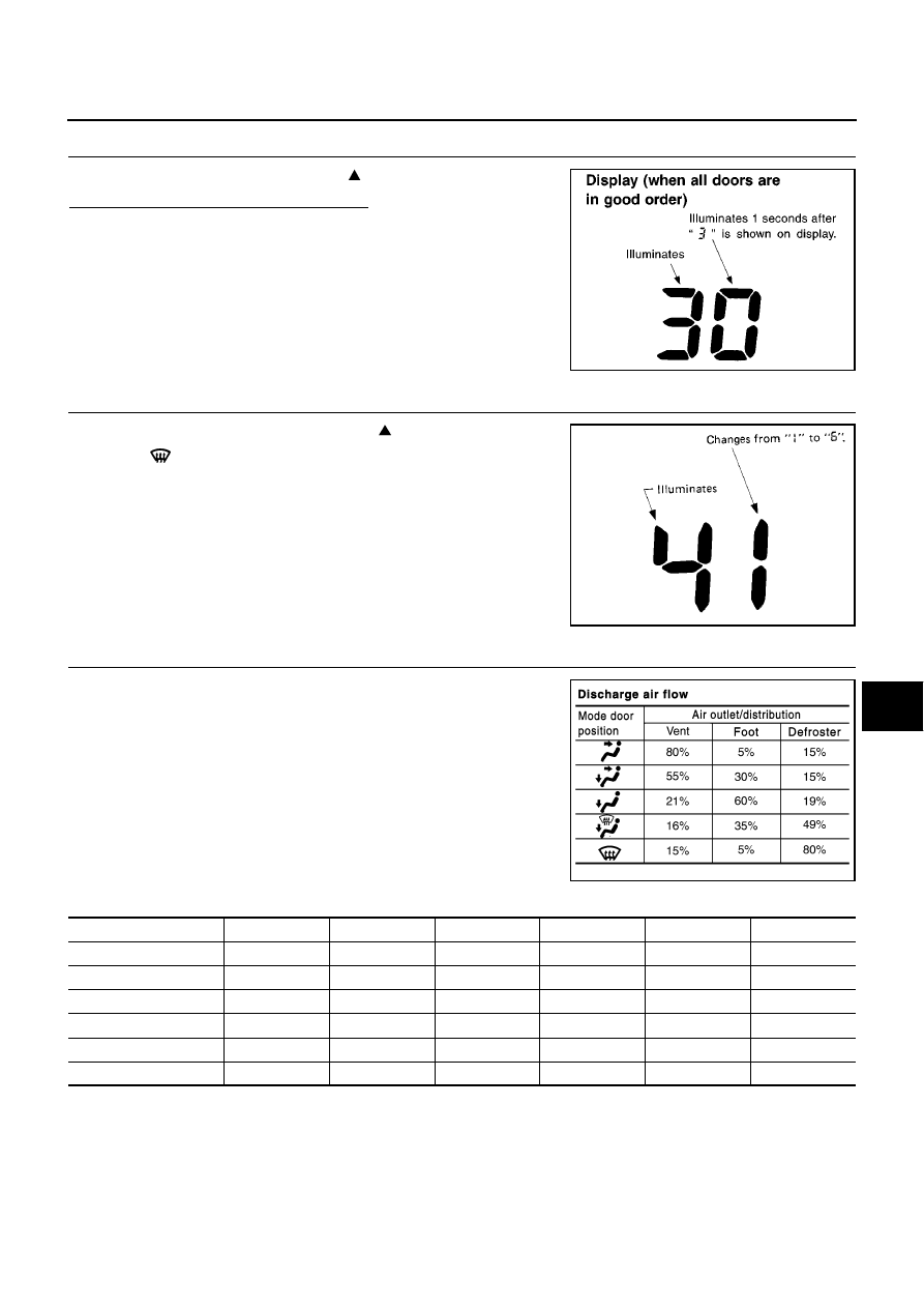
6.
STEP-3: AIR MIX DOOR AND MODE DOOR POSITIONS ARE CHECKED
Press temperature control switch (UP:
).
Does code No. 30 appear on the display?
YES
>> GO TO 7.
NO
>> GO TO 14.
7.
STEP-4: OPERATION OF EACH DOOR MOTOR IS CHECKED
1.
Press temperature control switch (UP:
).
2.
Press
(DEF) switch. Code No. of each door motor test is
indicated on the display.
>> GO TO 8.
8.
CHECK ACTUATORS
Refer to the following chart and confirm discharge air flow, air tem-
perature, blower motor voltage, compressor, ionizer and indicator
(ION mode) operation.
SJIA0738E
RHA495A
MJIB0374E
Code No.
41
42
43
44
45
46
Mode door position
VENT
B/L 1
B/L 2
FOOT
D/F
DEF
Intake door position
REC
REC
FRE
FRE
FRE
FRE
Air mix door position
FULL COLD
FULL COLD
50%
50%
FULL HOT
FULL HOT
Blower motor voltage
5V
10.5V
8.5V
8.5V
8.5V
Battery voltage
Compressor
ON
ON
ON
OFF
OFF
ON
Fan ON signal
12V
12V
12V
1V
1V
12V
ATC-50
TROUBLE DIAGNOSIS
Checks must be made visually, by listening to any noise, or by touching air outlets with your hand, etc. for
improper operation.
OK or NG
OK
>> GO TO 9.
NG
>>
●
Air outlet does not change.
Go to Mode Door Motor Circuit. Refer to
ATC-60, "Mode Door Motor Circuit"
.
●
Intake door does not change.
Go to Intake Door Motor Circuit. Refer to
ATC-68, "Intake Door Motor Circuit"
.
●
Blower motor operation is malfunctioning.
Go to Blower Motor Circuit. Refer to
ATC-71, "Blower Motor Circuit"
.
●
Magnet clutch does not engage.
Go to Magnet Clutch Circuit. Refer to
ATC-78, "Magnet Clutch Circuit"
.
●
Discharge air temperature does not change.
Go to Air Mix Door Motor Circuit. Refer to
ATC-64, "Air Mix Door Motor Circuit"
.
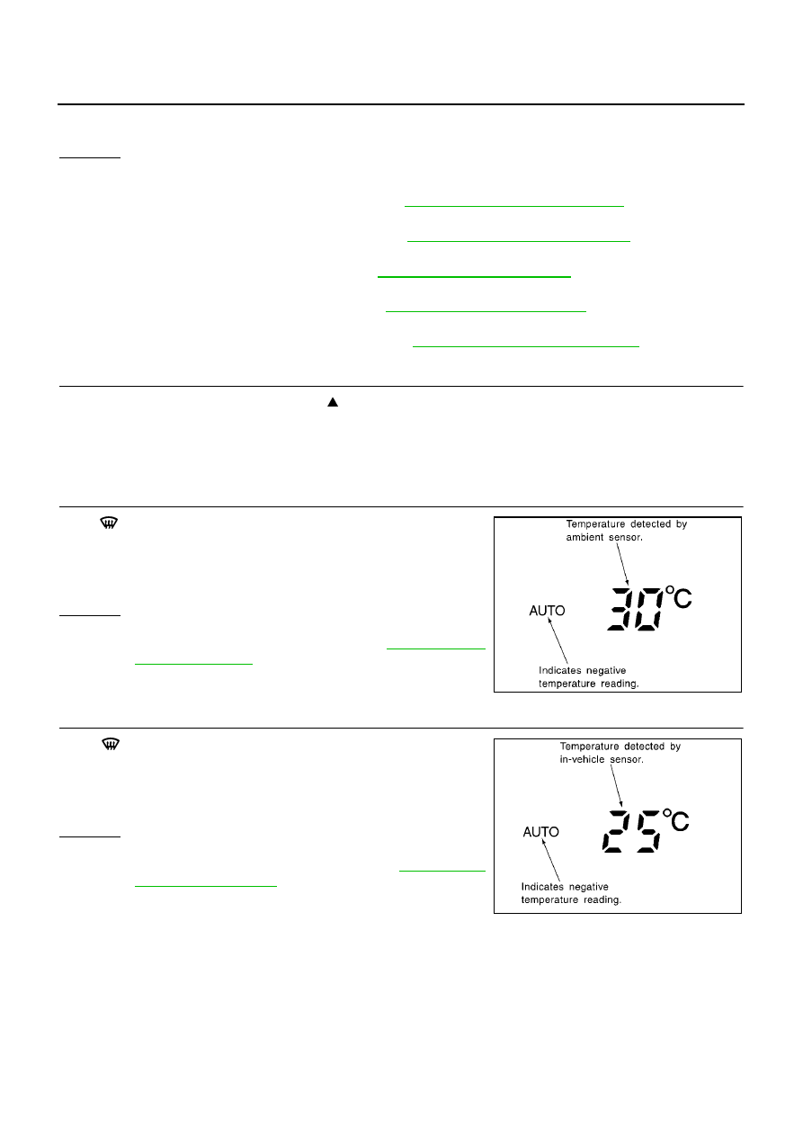
9.
STEP-5: TEMPERATURE OF EACH SENSOR IS CHECKED
1.
Press temperature control switch (UP:
).
2.
Code No. 5 appears on the display.
>> GO TO 10.
10.
CHECK AMBIENT SENSOR
Press
(DEF) switch one time. Temperature detected by ambient
sensor is indicated on the display.
NOTE:
If temperature shown on display greatly differs from actual tempera-
ture, check sensor circuit first, then inspect sensor.
OK or NG
OK
>> GO TO 11.
NG
>> Go to Ambient Sensor Circuit. Refer to
.
11.
CHECK IN-VEHICLE SENSOR
Press
(DEF) switch second time. Temperature detected by in-
vehicle sensor is indicated on the display.
NOTE:
If temperature shown on display greatly differs from actual tempera-
ture, check sensor circuit first, then inspect sensor.
OK or NG
OK
>> GO TO 12.
NG
>> Go to In-vehicle Sensor Circuit. Refer to
.
SJIA0744E
SJIA0746E
TROUBLE DIAGNOSIS
ATC-51
C
D
E
F
G
H
I
K
L
M
A
B
ATC
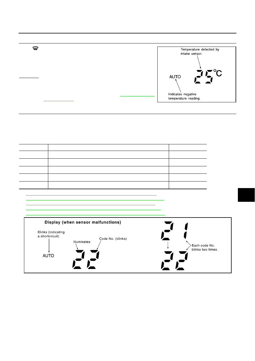
12.
CHECK INTAKE SENSOR
Press
(DEF) switch third time. Temperature detected by intake
sensor is indicated on the display.
NOTE:
If temperature shown on display greatly differs from actual tempera-
ture, check sensor circuit first, then inspect sensor.
OK or NG
OK
>> 1. Turn ignition switch OFF or AUTO switch ON.
2. INSPECTION END
NG
>> Go to Intake Sensor Circuit. Refer to
.
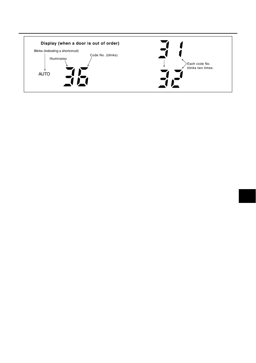
13.
CHECK MALFUNCTIONING SENSOR
Refer to the following chart for malfunctioning code No.
(If two or more sensors malfunction, corresponding code No. blink respectively twice.)
*1: Perform self-diagnosis STEP-2 under sunshine.
When performing indoors, aim a light (more than 60W) at sunload sensor, otherwise code No.25 will indicate
despite that sunload sensor is functioning properly.
*2:
ATC-99, "DIAGNOSTIC PROCEDURE FOR AMBIENT SENSOR"
.
*3:
ATC-102, "DIAGNOSTIC PROCEDURE FOR IN-VEHICLE SENSOR"
.
*4:
ATC-108, "DIAGNOSTIC PROCEDURE FOR INTAKE SENSOR"
.
*5:
ATC-105, "DIAGNOSTIC PROCEDURE FOR SUNLOAD SENSOR"
.
*6:
ATC-70, "DIAGNOSTIC PROCEDURE FOR INTAKE DOOR MOTOR"
.
>> INSPECTION END
SJIA0748E
Code No.
Malfunctioning sensor (Including circuits)
Reference page
21 /
AUTO
21
Ambient sensor
*2
22 /
AUTO
22
In-vehicle sensor
*3
24 /
AUTO
24
Intake sensor
*4
25 /
AUTO
25
Sunload sensor
*1
*5
26 /
AUTO
26
Intake door motor PBR
*6
SJIA0752E
ATC-52
TROUBLE DIAGNOSIS
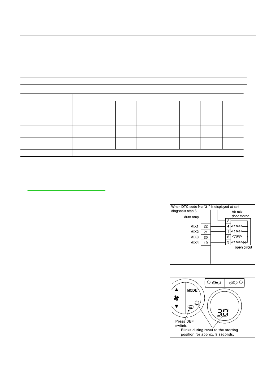
14.
CHECK MALFUNCTIONING DOOR MOTOR POSITION SWITCH
Air mix and/or mode door motor is/are malfunctioning.
Door motor corresponding to the DTC
DTC for an inoperative harness
(If two or more air mix or mode doors are out of order, corresponding code numbers blink respectively twice.)
*1: If air mix door motor harness connector is disconnected, the following display pattern will appear.
31
→
32
→
33
→
34
→
Return to 31
*2: If mode door motor harness connector is disconnected, the following display pattern will appear.
35
→
36
→
37
→
38
→
Return to 35
*3:
ATC-64, "Air Mix Door Motor Circuit"
.
*4:
ATC-60, "Mode Door Motor Circuit"
.
NOTE:
●
If all four terminals of each door motor show an open circuit,
there is probably a disconnected connector or an open circuit in
actuator drive power supply harness.
●
If a short circuit occurs in the harness between terminal for each
door motor and drive signal, although it cannot be detected by
self-diagnosis, the door motor will vibrate when it operate.
Door Motor Starting Position Reset
●
Pressing the DEF switch during STEP-3 will send a reset signal
to air mix door and mode door motor to reset them to the starting
position.
During reset: The 30 and DEF switch LED will blinks. (For
approx. 9 seconds)
Code No.*1 *2
31, 32, 33, 34
35, 36, 37, 38
Corresponding door motor
Air mix door
Mode door
Corresponding door motor
Air mix door motor
Mode door motor
Corresponding terminal
(Door motor side)
3
4
1
6
3
4
1
6
Corresponding terminal
(Auto amp. side)
19
22
21
20
23
26
25
24
Code number for short cir-
cuit
AUTO
31
AUTO
32
AUTO
33
AUTO
34
AUTO
35
AUTO
36
AUTO
37
AUTO
38
Code number for open cir-
cuit
31
32
33
34
35
36
37
38
Reference Page
*3
*4
SJIA0951E
SJIA0952E
TROUBLE DIAGNOSIS
ATC-53
C
D
E
F
G
H
I
K
L
M
A
B
ATC
>> INSPECTION END
SJIA0757E
ATC-54
TROUBLE DIAGNOSIS
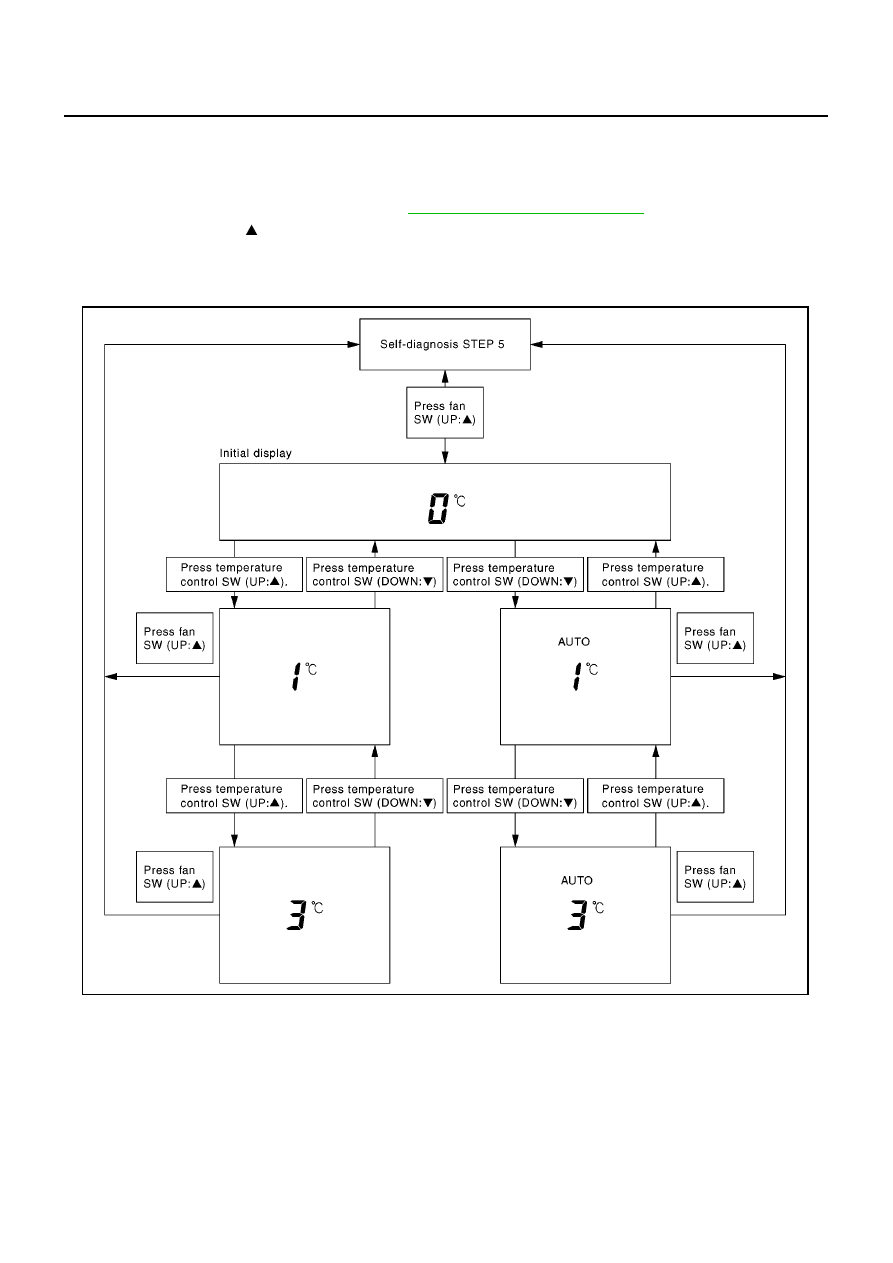
AUXILIARY MECHANISM: TEMPERATURE SETTING TRIMMER
The trimmer compensates for differences in range of
±
3
°
C between temperature setting (displayed digitally)
and temperature felt by driver.
Operating procedures for this trimmer are as follows:
1.
Begin self-diagnosis STEP-5 mode. Refer to
ATC-46, "Self-diagnosis Function"
.
2.
Press fan switch (UP: ) to set system in auxiliary mode.
3.
Display shows 0
°
C in auxiliary mechanism.
4.
Press temperature control switch as desired. Temperature will change at a rate of 1
°
C each time a switch
is pressed.
When battery cable is disconnected or battery voltage is 9.0V or less, trimmer operation is canceled. Set
temperature returns to the initial condition, i.e. 0
°
C.
SJIA0761E
TROUBLE DIAGNOSIS
ATC-55
C
D
E
F
G
H
I
K
L
M
A
B
ATC
Operational Check
BJS000BD
The purpose of the operational check is to confirm that the system operates properly.
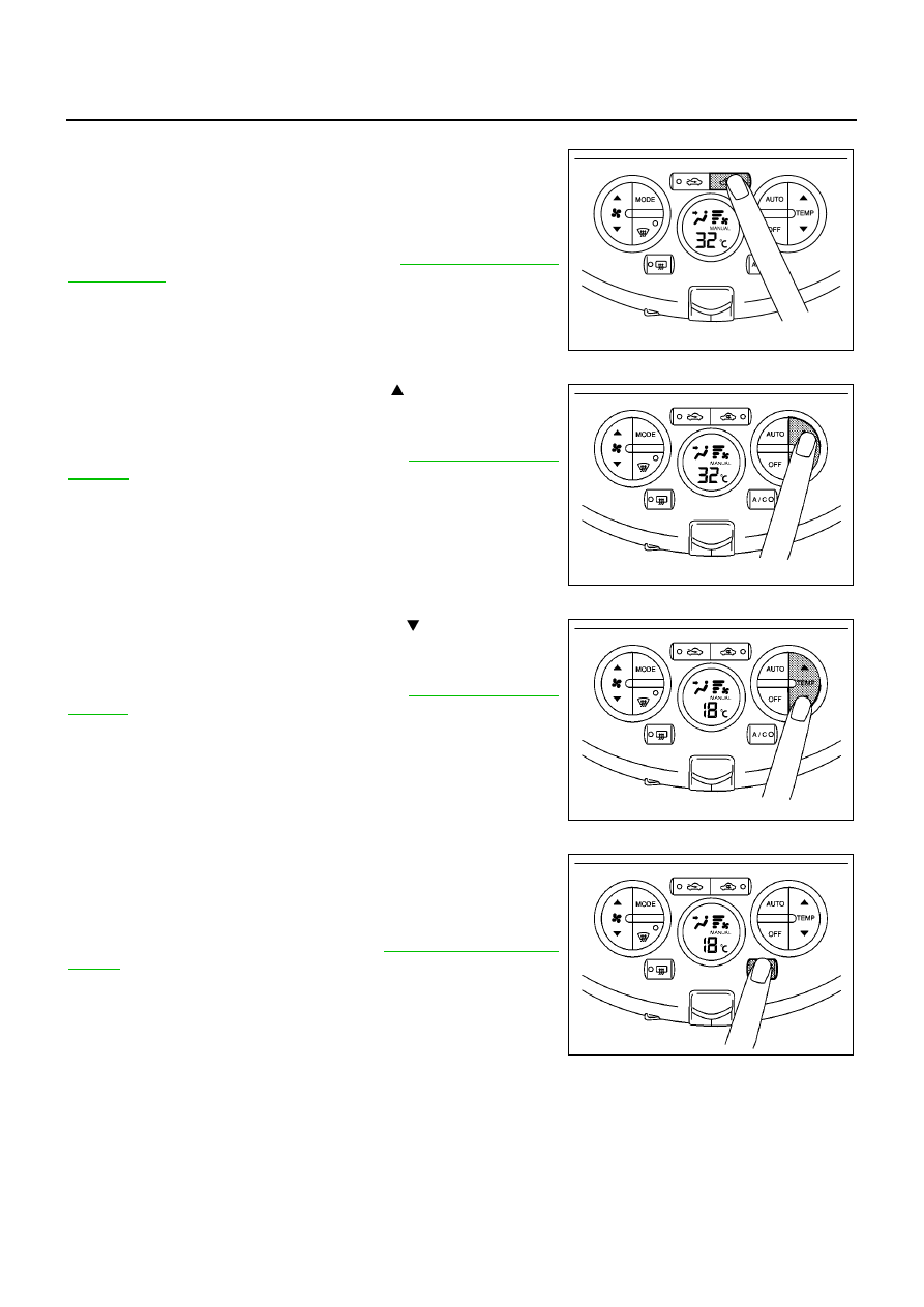
CHECKING MEMORY FUNCTION
1.
Press temperature control switch (UP:
) until
32
°
C is dis-
played.
2.
Press OFF switch.
3.
Turn the ignition switch OFF.
4.
Turn the ignition switch ON.
5.
Press the AUTO switch.
6.
Confirm that the set temperature remains at previous tempera-
ture.
7.
Press OFF switch.
If NG, go to trouble diagnosis procedure for
.
If OK, continue the check.
CHECKING BLOWER
1.
Press fan switch (UP:
). Blower should operate on low speed.
The fan symbol should have one blade lit.
2.
Press fan switch (UP:
), and continue checking blower speed
and fan symbol until all speeds are checked.
3.
Leave blower on max. speed.
If NG, go to trouble diagnosis procedure for
.
If OK, continue the check.
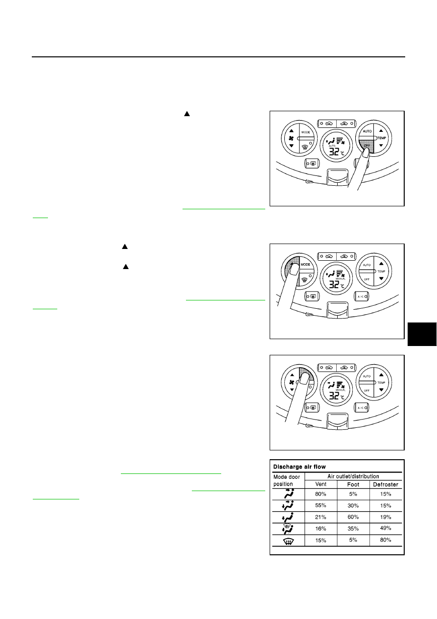
CHECKING DISCHARGE AIR
1.
Press MODE switch and DEF switch.
2.
Each position indicator should change shape.
3.
Confirm that discharge air comes out according to the air distri-
bution table. Refer to
.
Intake door position is checked in the next step.
If NG, go to trouble diagnosis procedure for
.
If OK, continue the check.
NOTE:
Confirm that the compressor clutch is engaged (sound or visual
inspection) and intake door position is at FRESH when the DEF is
selected.
Conditions
: Engine running at usual operating temperature
MJIB0375E
MJIB0376E
MJIB0377E
MJIB0374E
ATC-56
TROUBLE DIAGNOSIS
CHECKING RECIRCULATION
1.
Press recirculation (REC) switch one time. Recirculation LED
should illuminate.
2.
Press fresh (FRE) switch one time. Fresh LED should illuminate.
3.
Listen for intake door position change (you should hear blower
sound change slightly).
If NG, go to trouble diagnosis procedure for
.
If OK, continue the check.
CHECKING TEMPERATURE INCREASE
1.
Press temperature control switch (UP:
) until 32
°
C is dis-
played.
2.
Check for hot air at discharge air outlets.
If NG, go to trouble diagnosis procedure for
.
If OK, continue the check.
CHECKING TEMPERATURE DECREASE
1.
Press temperature control switch (DOWN:
) until 18
°
C is dis-
played.
2.
Check for cold air at discharge air outlets.
If NG, go to trouble diagnosis procedure for
.
If OK, continue the check.
CHECK A/C SWITCH
1.
Press AUTO and A/C switches.
2.
A/C switch LED will turn ON.
●
Confirm that the compressor clutch engages (sound or visual
inspection).
If NG, go to trouble diagnosis procedure for
.
If OK, continue the check.
MJIB0378E
MJIB0379E
MJIB0380E
MJIB0381E
TROUBLE DIAGNOSIS
ATC-57
C
D
E
F
G
H
I
K
L
M
A
B
ATC
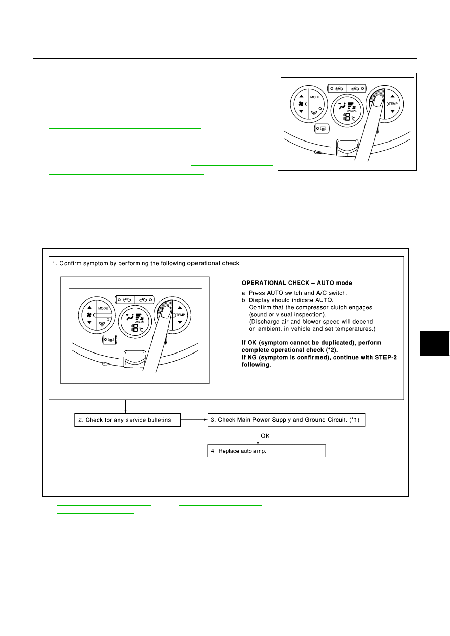
CHECKING AUTO MODE
1.
Press AUTO switch.
2.
Display should indicate AUTO.
●
Confirm that discharge air and blower speed will depend on
ambient, in-vehicle, and set temperatures.
●
If NG, go to trouble diagnosis procedure for
Supply and Ground Circuit for Auto Amp."
, then if necessary,
trouble diagnosis procedure for
ATC-78, "Magnet Clutch Circuit"
.
●
If all operational checks are OK (symptom cannot be dupli-
cated), go to Incident Simulation Tests in
Efficient Diagnosis for an Electrical Incident"
and perform tests
as outlined to simulate driving conditions environment.
●
If symptom appears, refer to
and perform applicable trouble diagnosis pro-
cedures.
Power Supply and Ground Circuit for Auto Amp.
BJS000BE
SYMPTOM: A/C system does not come on.
INSPECTION FLOW
MJIB0382E
*1
ATC-58, "DIAGNOSTIC PROCE-
DURE FOR A/C SYSTEM"
*2
MJIB0383E
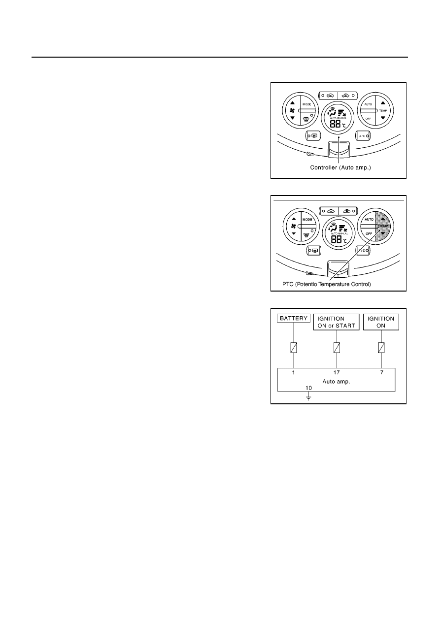
ATC-58
TROUBLE DIAGNOSIS
COMPONENT DESCRIPTION
Auto Amp. (Automatic Amplifier)
The auto amp. has a built-in microcomputer which processes infor-
mation sent from various sensors needed for air conditioner opera-
tion. The air mix door motor, mode door motor, intake door motor,
blower motor and compressor are then controlled.
The auto amp. is unitized with control mechanisms. Signal from vari-
ous switches and Potentio Temperature Control (PTC) are directly
entered into auto amp.
Self-diagnostic functions are also built into auto amp. to provide
quick check of malfunctions in the auto air conditioner system.
Potentio Temperature Control (PTC)
The PTC is built into the auto amp. It can be set at an interval of 1
°
C
in the 18
°
C to 32
°
C temperature range by pressing temperature con-
trol switch. The set temperature is displayed.
DIAGNOSTIC PROCEDURE FOR A/C SYSTEM
SYMPTOM: A/C system does not come on.
MJIB0370E
MJIB0384E
SJIA0785E
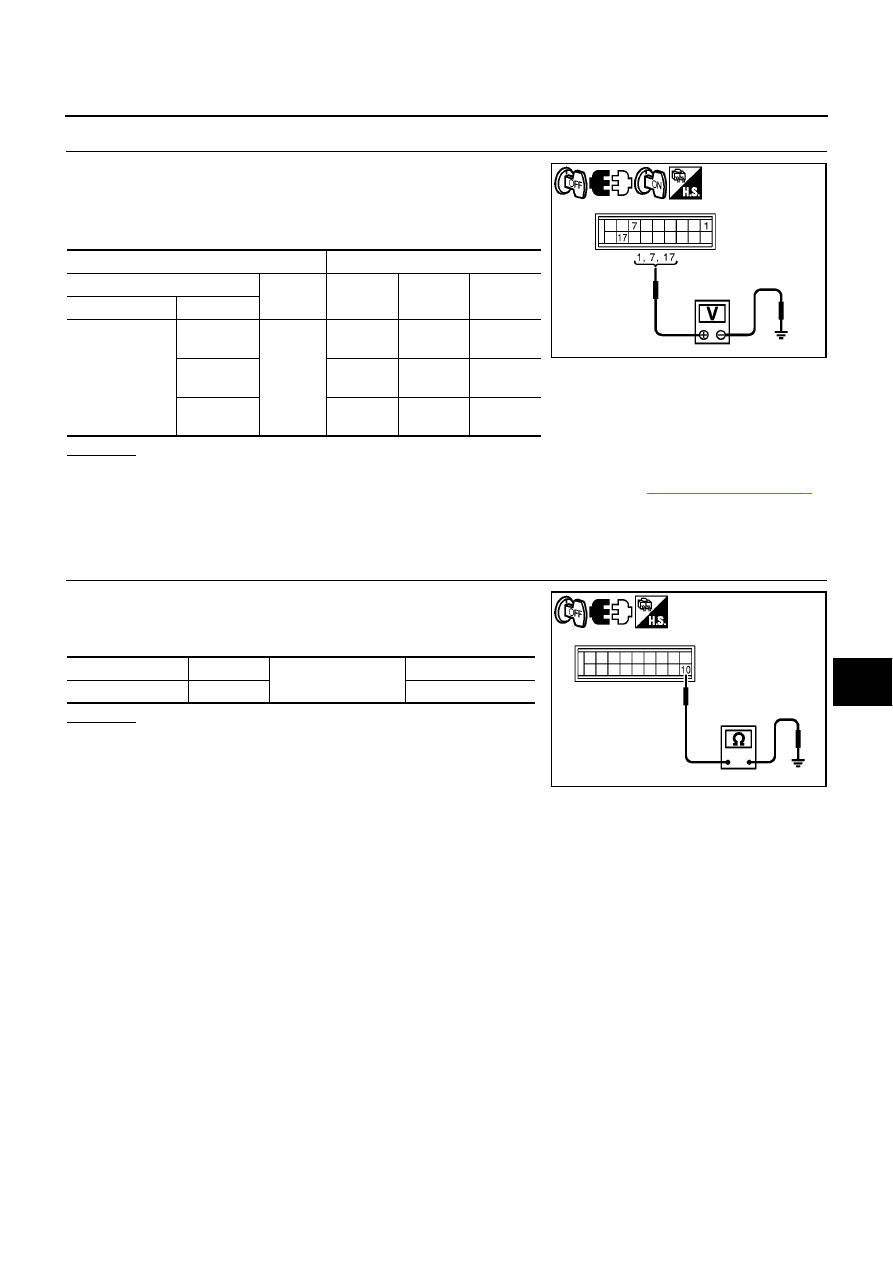
TROUBLE DIAGNOSIS
ATC-59
C
D
E
F
G
H
I
K
L
M
A
B
ATC
1.
CHECK POWER SUPPLY CIRCUIT FOR AUTO AMP.
1.
Turn ignition switch OFF.
2.
Disconnect auto amp. connector.
3.
Check voltage between auto amp. harness connector and
ground.
OK or NG
OK
>> GO TO 2.
NG
>> Check 10A fuses (Nos. 5, 7 and 19, located in the fuse block). Refer to
.
●
If fuses are OK, check harness for open circuit. Repair or replace if necessary.
●
If fuses are NG, replace fuse and check harness for short circuit. Repair or replace if necessary.
2.
CHECK GROUND CIRCUIT FOR AUTO AMP.
1.
Turn ignition switch OFF.
2.
Check continuity between auto amp. harness connector and
ground.
OK or NG
OK
>> Replace auto amp.
NG
>> Repair or replace harness.
Terminals
Ignition switch position
(+)
(-)
OFF
ACC
ON
Connector
Terminal
Auto amp.: M64
1
Ground
Battery
voltage
Battery
voltage
Battery
voltage
7
Approx.
0V
Approx.
0V
Battery
voltage
17
Approx.
0V
Approx.
0V
Battery
voltage
MJIB0433E
Connector
Terminal
Ground
Continuity
Auto amp.: M64
10
Yes
MJIB0434E
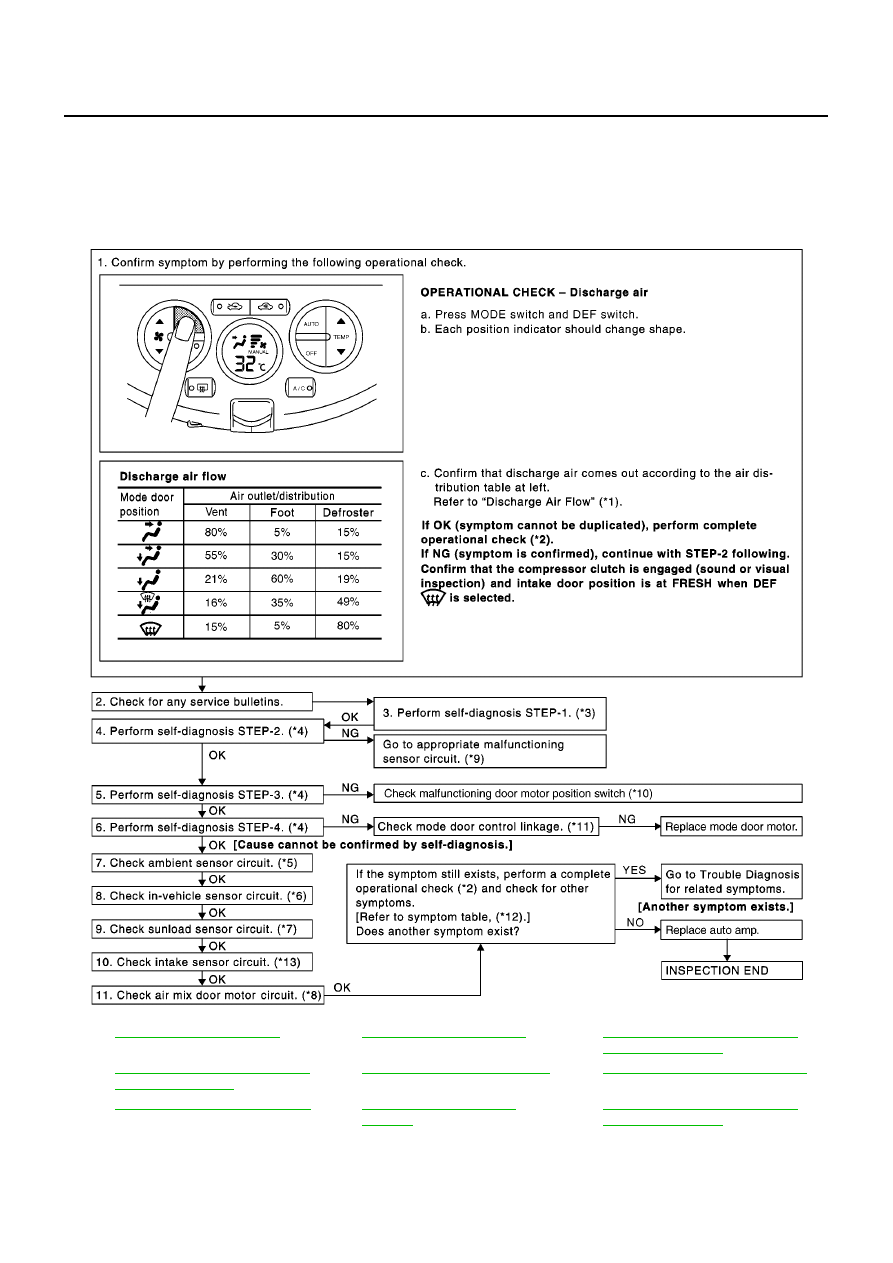
ATC-60
TROUBLE DIAGNOSIS
Mode Door Motor Circuit
BJS000BF
SYMPTOM:
●
Air outlet does not change.
●
Mode door motor does not operate normally.
INSPECTION FLOW
*1
*2
*3
ATC-48, "FUNCTION CONFIRMA-
TION PROCEDURE"
, see No. 1.
*4
ATC-48, "FUNCTION CONFIRMA-
TION PROCEDURE"
, see No. 5 to 7.
*5
ATC-99, "Ambient Sensor Circuit"
*6
ATC-102, "In-vehicle Sensor Circuit"
*7
ATC-105, "Sunload Sensor Circuit"
*8
*9
ATC-48, "FUNCTION CONFIRMA-
TION PROCEDURE"
, see No. 13.
MJIB0385E
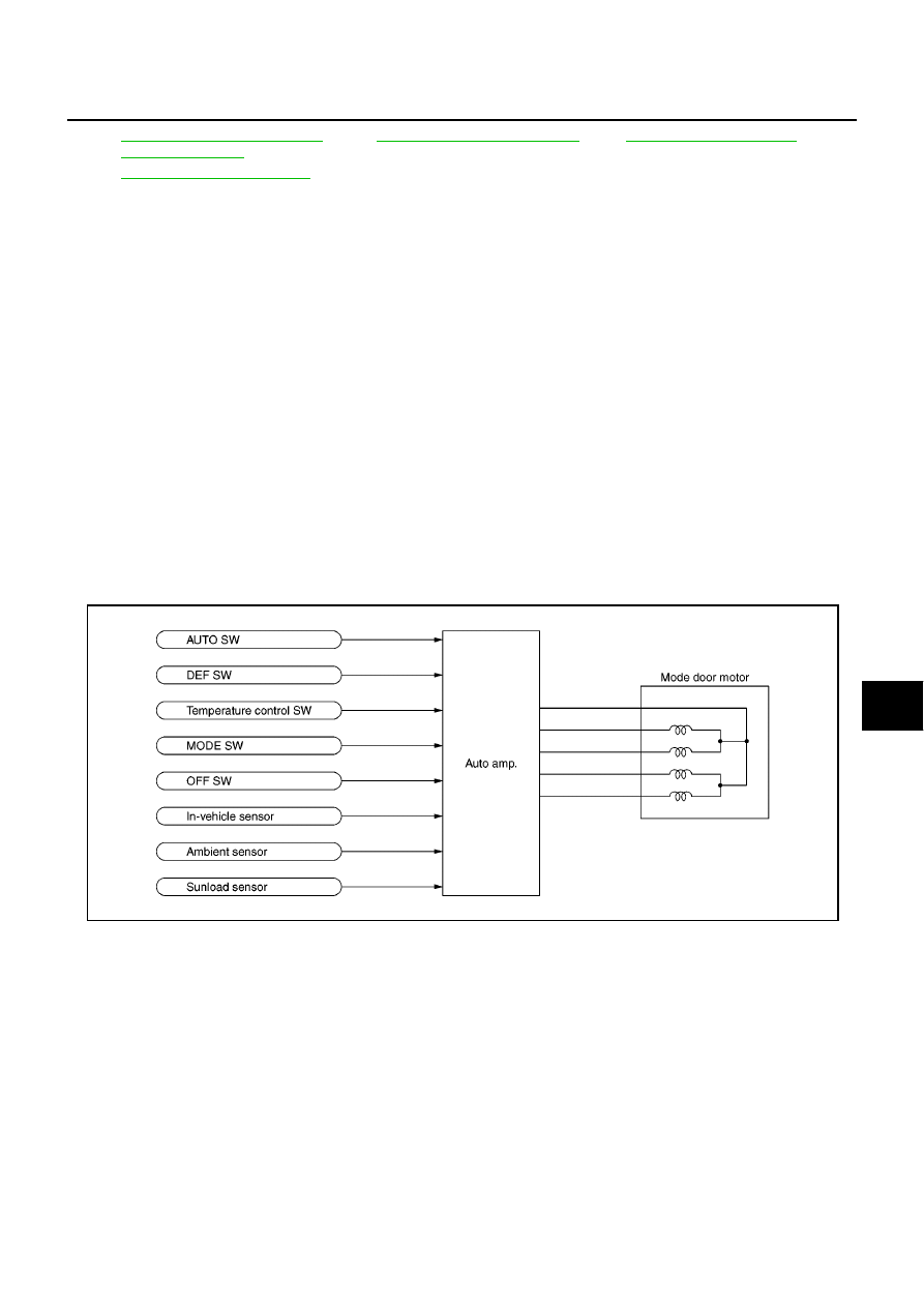
TROUBLE DIAGNOSIS
ATC-61
C
D
E
F
G
H
I
K
L
M
A
B
ATC
SYSTEM DESCRIPTION
Component Parts
Mode door control system components are:
●
Auto amp.
●
Mode door motor
●
In-vehicle sensor
●
Ambient sensor
●
Sunload sensor
System Operation
The auto amp. receives data from each of the sensors. When a drive signal is input from auto amp. to door
motor, a step motor built into the door motor rotates according to the drive signal, and then stops at the posi-
tion of target door.
Mode door changes to manual select mode by pressing MODE/DEF switch of the controller. That allows mode
door to be fixed.
Pressing AUTO switch allows automatic control by auto amp., and mode door is fixed in the FOOT position by
pressing OFF switch.
During automatic operation of mode door, mode door position (VENT, B/L, FOOT) is selected according to the
temperature of discharge air calculated by auto amp. based on the target opening angle of air mix door and
the amount of sunload. And only when ambient temperature is extremely low with the mode door in the FOOT
position, D/F is selected and prevents windshield fogging.
*10
ATC-48, "FUNCTION CONFIRMA-
TION PROCEDURE"
see No. 14.
*11
*12
*13
ATC-108, "Intake Sensor Circuit"
SJIA0788E
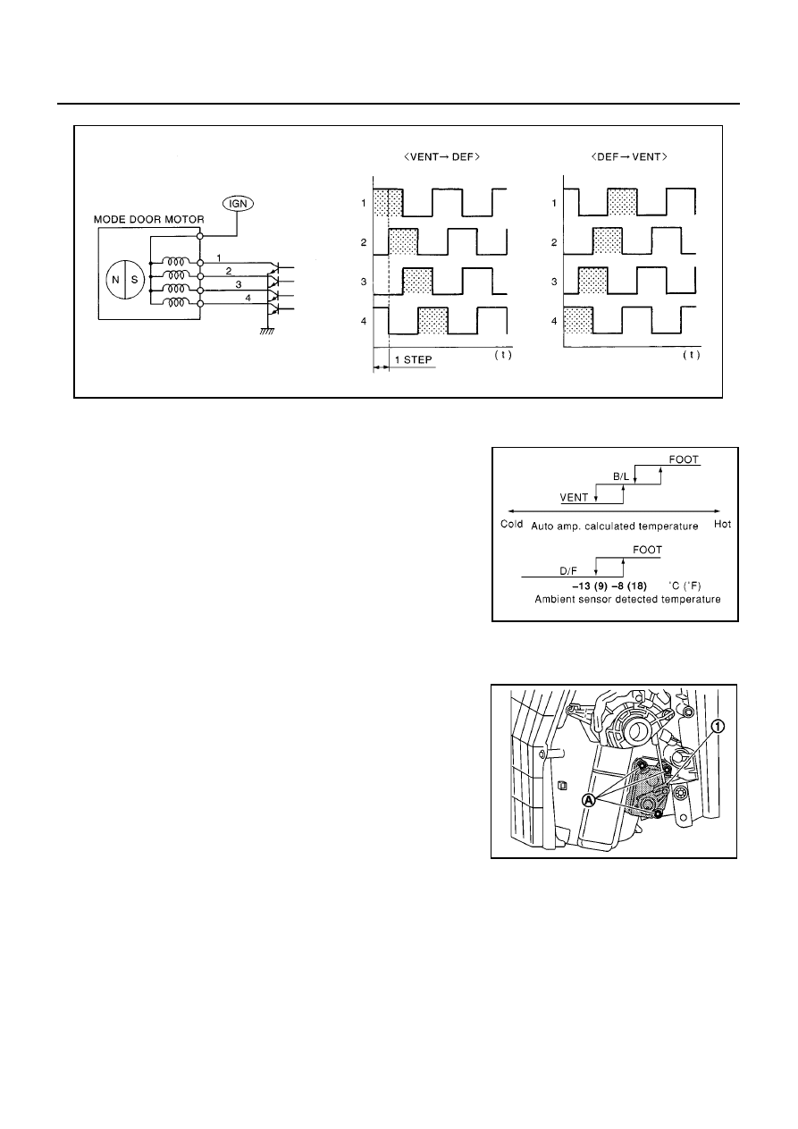
ATC-62
TROUBLE DIAGNOSIS
Drive System of Step Motor Type Door Motor
●
Motor is actuated in sequence by energizing four drive coils.
●
Rotation direction can be changed by changing pattern of excitation.
Mode Door Control Specification
COMPONENT DESCRIPTION
Mode Door Motor
The mode door motor is attached to the A/C unit assembly. It rotates
so that air is discharged from the outlet set by the auto amp. Motor
rotation is conveyed to a link which activates the mode door.
SJIA0971E
RHA384HA
MJIB0463E
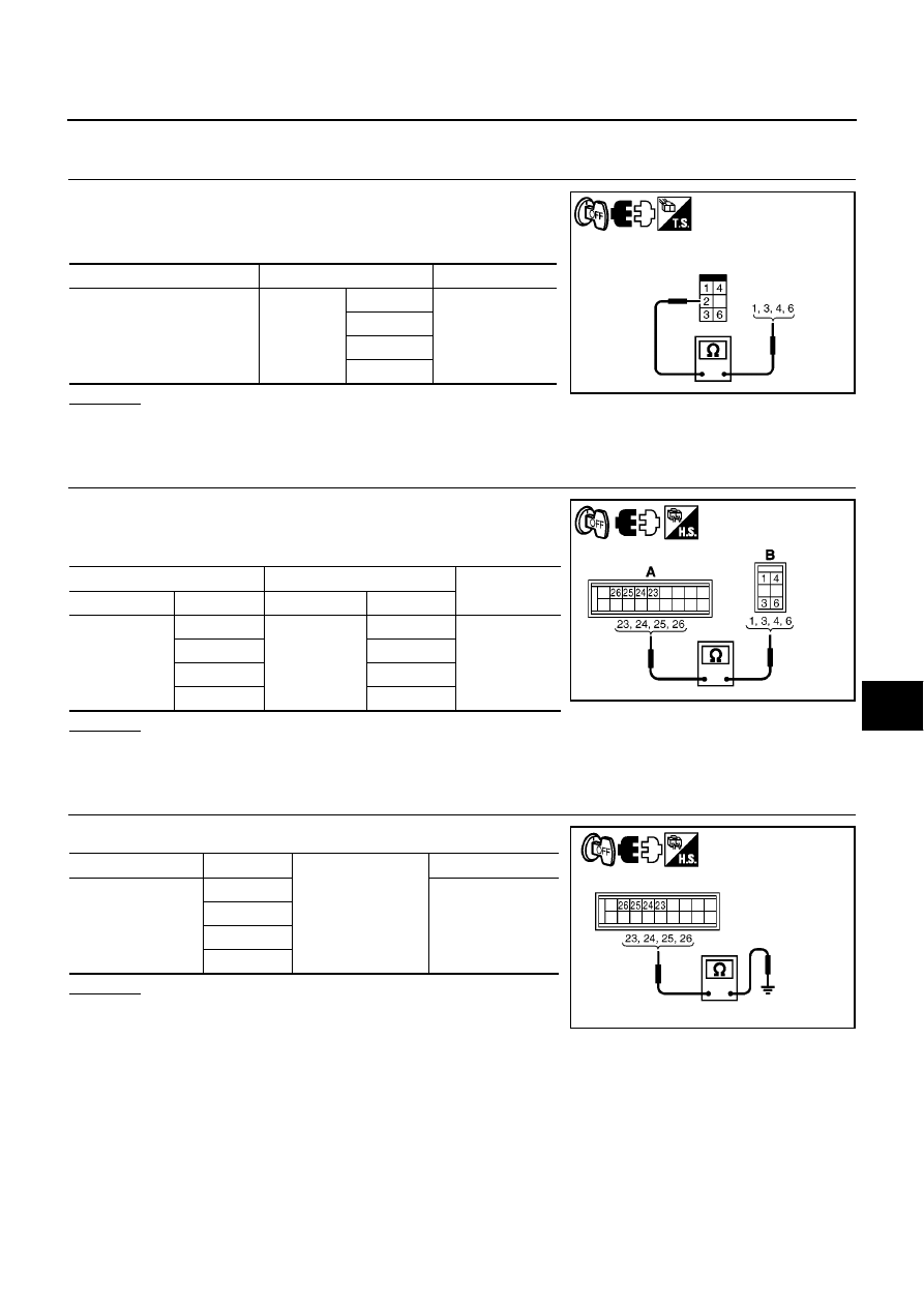
TROUBLE DIAGNOSIS
ATC-63
C
D
E
F
G
H
I
K
L
M
A
B
ATC
DIAGNOSTIC PROCEDURE FOR MODE DOOR MOTOR
1.
CHECK MODE DOOR MOTOR
1.
Turn ignition switch OFF.
2.
Disconnect mode door motor connector.
3.
Check continuity between mode door motor connector terminal.
OK or NG
OK
>> GO TO 2.
NG
>> Replace mode door motor.
2.
CHECK CIRCUIT CONTINUITY BETWEEN AUTO AMP. AND MODE DOOR MOTOR
1.
Disconnect auto amp. connector.
2.
Check continuity between auto amp. harness connector (A) and
mode door motor harness connector (B).
OK or NG
OK
>> GO TO 3.
NG
>> Repair harness or connector.
3.
CHECK CIRCUIT CONTINUITY BETWEEN AUTO AMP. AND GROUND
Check continuity between auto amp. harness connector and ground.
OK or NG
OK
>> Replace auto amp.
NG
>> Repair harness or connector.
Connector
Terminals
Continuity
Mode door motor: M50
2
1
Yes
3
4
6
SJIA0948E
A
B
Continuity
Connector
Terminal
Connector
Terminal
Auto amp.:
M65
23
Mode door
motor: M50
3
Yes
24
6
25
1
26
4
MJIB0386E
Connector
Terminal
Ground
Continuity
Auto amp.: M65
23
No
24
25
26
MJIB0387E
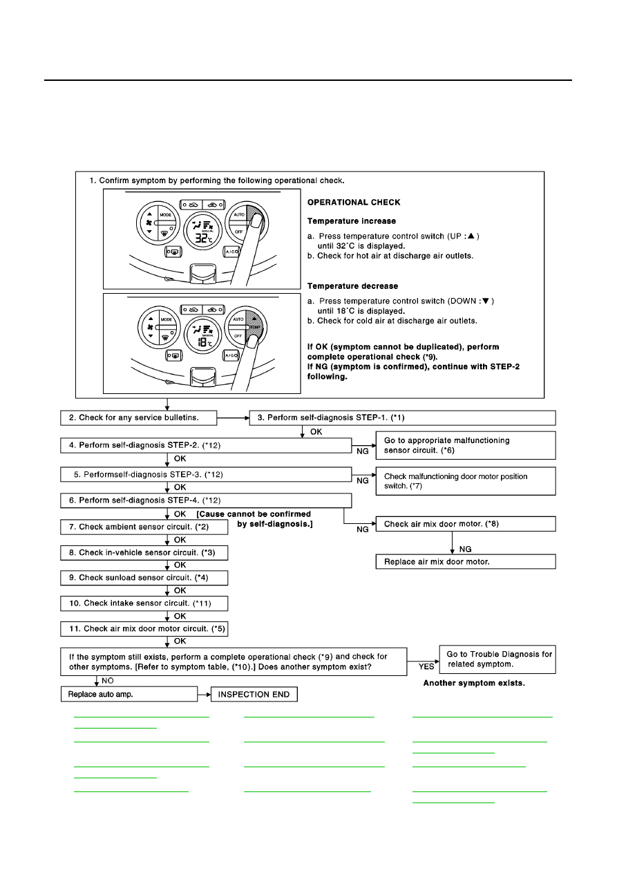
ATC-64
TROUBLE DIAGNOSIS
Air Mix Door Motor Circuit
BJS000BG
SYMPTOM:
●
Discharge air temperature does not change.
●
Air mix door motor does not operate.
INSPECTION FLOW
*1
ATC-48, "FUNCTION CONFIRMA-
TION PROCEDURE"
, see No. 1.
*2
ATC-99, "Ambient Sensor Circuit"
*3
ATC-102, "In-vehicle Sensor Circuit"
*4
ATC-105, "Sunload Sensor Circuit"
*5
ATC-64, "Air Mix Door Motor Circuit"
*6
ATC-48, "FUNCTION CONFIRMA-
TION PROCEDURE"
, see No. 13.
*7
ATC-48, "FUNCTION CONFIRMA-
TION PROCEDURE"
, see No. 14.
*8
ATC-64, "Air Mix Door Motor Circuit"
*9
*10
*11
ATC-108, "Intake Sensor Circuit"
*12
ATC-48, "FUNCTION CONFIRMA-
TION PROCEDURE"
, see No. 5 to 7.
MJIB0388E
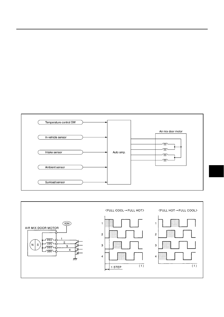
TROUBLE DIAGNOSIS
ATC-65
C
D
E
F
G
H
I
K
L
M
A
B
ATC
SYSTEM DESCRIPTION
Component Parts
Air mix door control system components are:
●
Auto amp.
●
Air mix door motor
●
In-vehicle sensor
●
Intake sensor
●
Ambient sensor
●
Sunload sensor
System Operation
The auto amp. receives data from each of the sensors. When setting a target temperature by using tempera-
ture button, auto amp. corrects preset temperature, performs an arithmetical operation based on signals from
sensors and determines opening angle of target air mix door.
Air mix door is constantly controlled so as to keep optimum opening angle of air mix door based on target and
present opening angles of air mix door. Air mix door is fixed in the full cold position when preset temperature is
set to 18
°
C, and full hot position when set to 32
°
C.
Drive System of Step Motor Type Door Motor
●
Motor is actuated in sequence by energizing four drive coils.
●
Rotation direction can be changed by changing pattern of excitation.
SJIA0789E
SJIA0970E
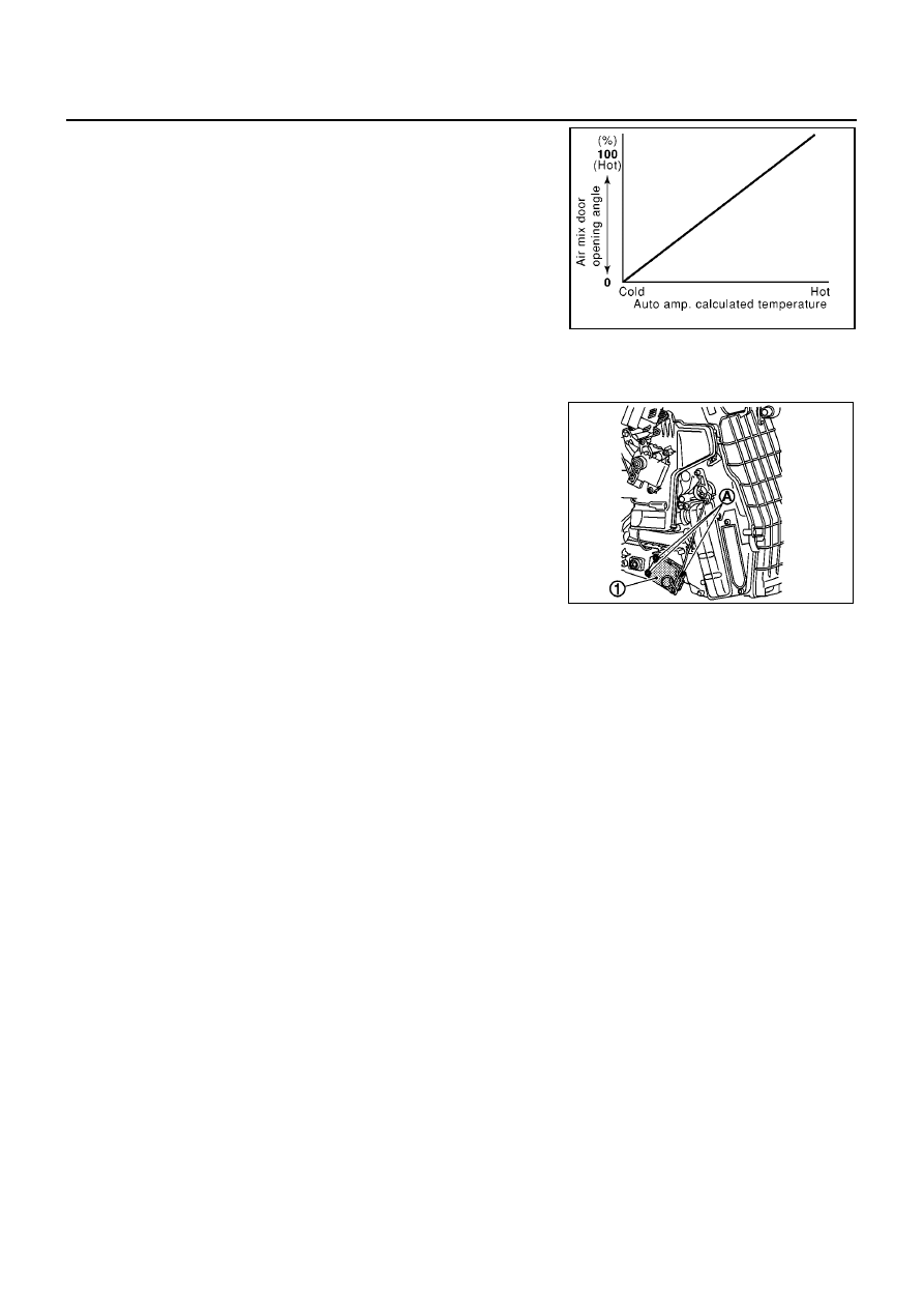
ATC-66
TROUBLE DIAGNOSIS
Air Mix Door Control Specification
COMPONENT DESCRIPTION
Air Mix Door Motor
The air mix door motor is attached to the A/C unit assembly. It
rotates so that the air mix door is opened or closed to a position set
by the auto amp. Motor rotation is conveyed through a shaft and the
air mix door position is then feedback to the auto amp. by PBR built-
in air mix door motor.
RHA457H
MJIB0464E
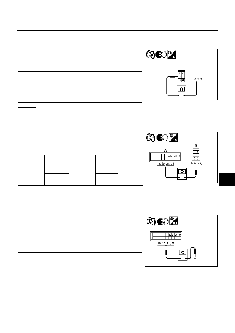
TROUBLE DIAGNOSIS
ATC-67
C
D
E
F
G
H
I
K
L
M
A
B
ATC
DIAGNOSTIC PROCEDURE FOR AIR MIX DOOR MOTOR
1.
CHECK AIR MIX DOOR MOTOR
1.
Turn ignition switch OFF.
2.
Disconnect air mix door motor connector.
3.
Check continuity between air mix door motor connector termi-
nals.
OK or NG
OK
>> GO TO 2.
NG
>> Replace air mix door motor.
2.
CHECK CIRCUIT CONTINUITY BETWEEN AUTO AMP. AND AIR MIX DOOR MOTOR
1.
Disconnect auto amp. connector.
2.
Check continuity between auto amp. harness connector (A) and
air mix door motor harness connector (B).
OK or NG
OK
>> GO TO 3.
NG
>> Repair harness or connector.
3.
CHECK CIRCUIT CONTINUITY BETWEEN AUTO AMP. AND GROUND
Check continuity between auto amp. harness connector and ground.
OK or NG
OK
>> Replace auto amp.
NG
>> Repair harness or connector.
Connector
Terminals
Continuity
Air mix motor: M51
2
1
Yes
3
4
6
SJIA0948E
A
B
Continuity
Connector
Terminal
Connector
Terminal
Auto amp.: M65
19
Air mix door
motor: M51
3
Yes
20
6
21
1
22
4
MJIB0389E
Connector
Terminal
Ground
Continuity
Auto amp.: M65
19
No
20
21
22
MJIB0390E
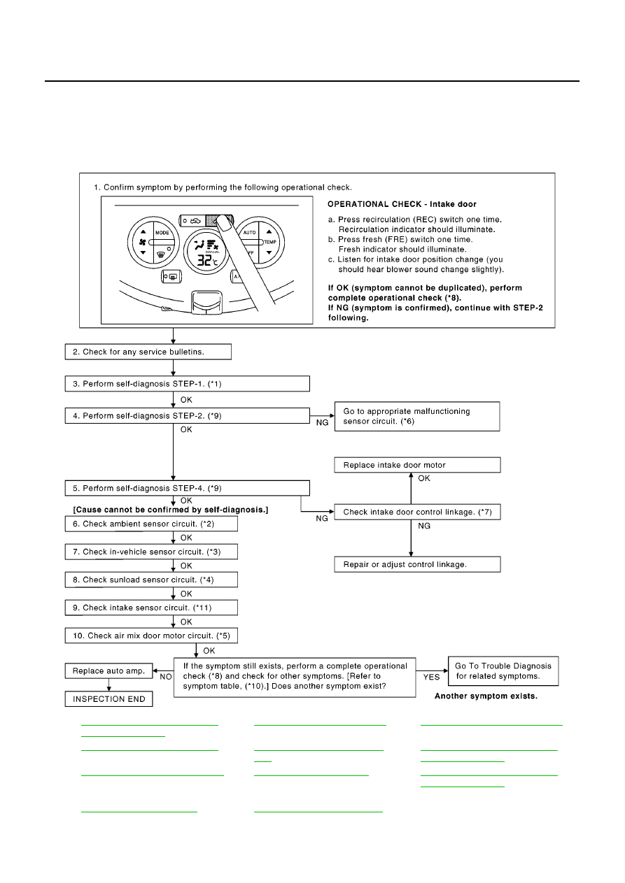
ATC-68
TROUBLE DIAGNOSIS
Intake Door Motor Circuit
BJS000BH
SYMPTOM:
●
Intake door does not change.
●
Intake door motor does not operate normally.
INSPECTION FLOW
*1
ATC-48, "FUNCTION CONFIRMA-
TION PROCEDURE"
, see No. 1.
*2
ATC-99, "Ambient Sensor Circuit"
*3
ATC-102, "In-vehicle Sensor Circuit"
*4
ATC-105, "Sunload Sensor Circuit"
*5
ATC-64, "Air Mix Door Motor Cir-
cuit"
*6
ATC-48, "FUNCTION CONFIRMA-
TION PROCEDURE"
, see No. 13.
*7
*8
*9
ATC-48, "FUNCTION CONFIRMA-
TION PROCEDURE"
, see No. 5 to
7.
*10
*11
ATC-108, "Intake Sensor Circuit"
MJIB0391E
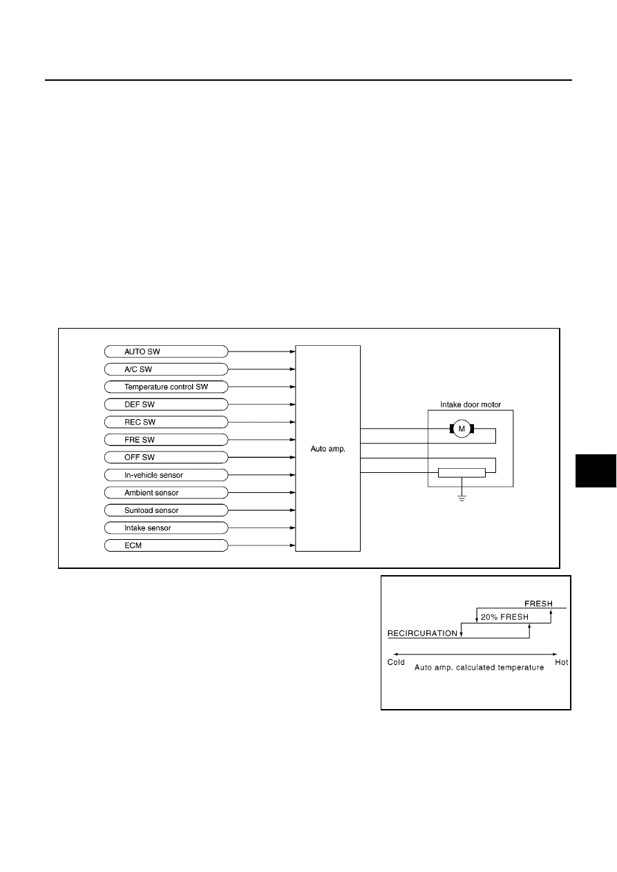
TROUBLE DIAGNOSIS
ATC-69
C
D
E
F
G
H
I
K
L
M
A
B
ATC
SYSTEM DESCRIPTION
Component Parts
Intake door control system components are:
●
Auto amp.
●
Intake door motor
●
In-vehicle sensor
●
Ambient sensor
●
Sunload sensor
●
Intake sensor
●
ECM
System Operation
Suction opening is basically fixed in the position FRESH when DEF switch, FRE switch, or OFF switch (only at
the time of REC switch OFF) is pressed or when A/C switch is OFF. It is fixed in the position RECIRCULATION
when REC switch is pressed. It is automatically controlled at all other times.
During automatic control of suction opening, any of FRESH, 20% FRESH and RECIRCULATION is selected
according to the target opening angle of air mix door calculated by auto amp. based on the in-vehicle temper-
ature, ambient temperature and the amount of solar radiation.
Intake Door Control Specification
SJIA0790E
RHA383H
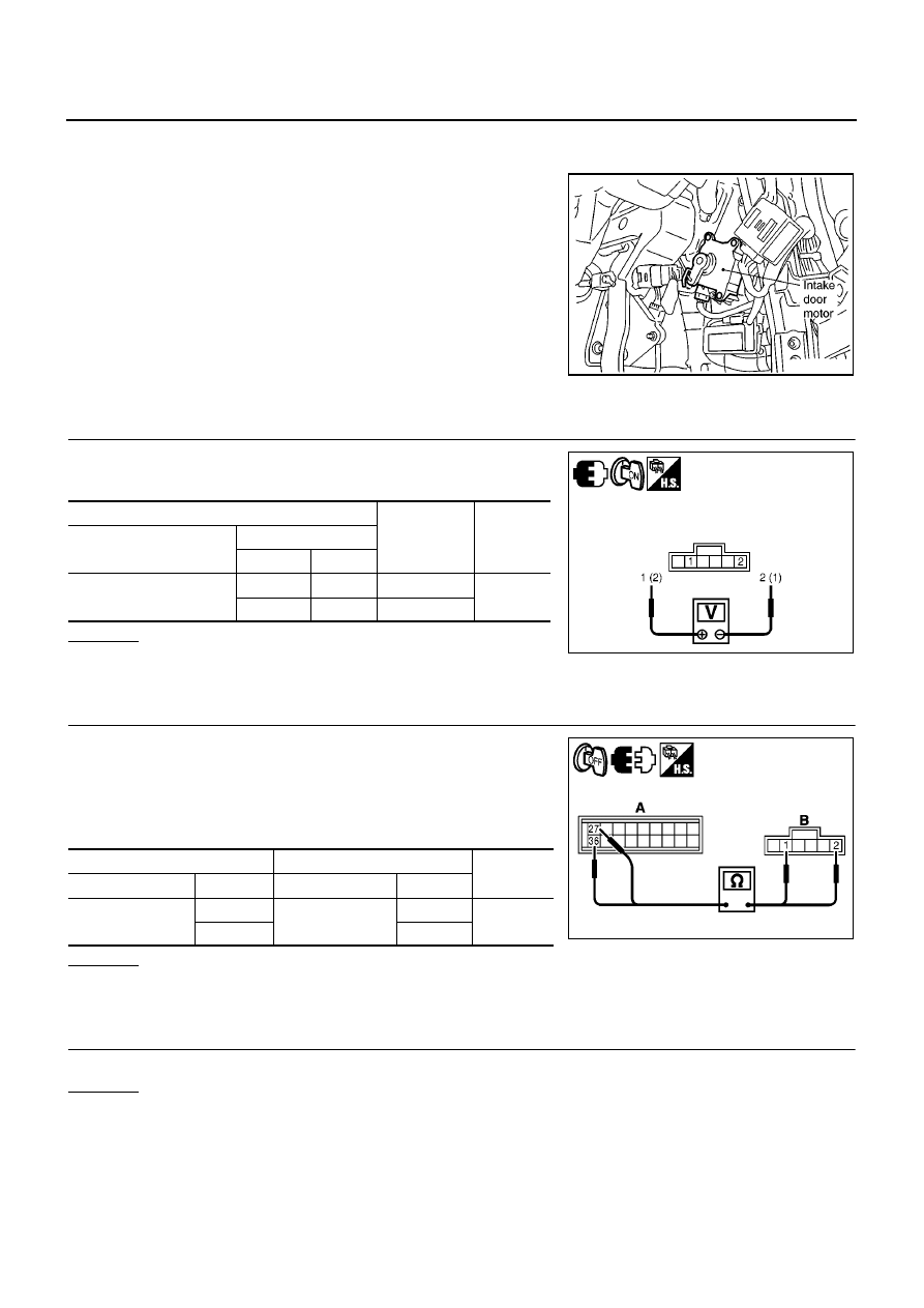
ATC-70
TROUBLE DIAGNOSIS
COMPONENT DESCRIPTION
Intake Door Motor
The intake door motor is attached to the A/C unit assembly. It rotates
so that air is drawn from inlets set by the auto amp. Motor rotation is
conveyed to a lever which activates the intake door.
DIAGNOSTIC PROCEDURE FOR INTAKE DOOR MOTOR
1.
CHECK POWER SUPPLY FOR INTAKE DOOR MOTOR
1.
Turn ignition switch ON.
2.
Check voltage between intake door motor harness connector.
OK or NG
OK
>> Replace intake door motor.
NG
>> GO TO 2.
2.
CHECK CIRCUIT CONTINUITY BETWEEN AUTO AMP. AND INTAKE DOOR MOTOR
1.
Turn ignition switch OFF.
2.
Disconnect auto amp. connector.
3.
Disconnect intake door motor connector.
4.
Check continuity between auto amp. harness connector (A) and
intake door motor harness connector (B).
OK or NG
OK
>> GO TO 3.
NG
>> Repair harness or connector.
3.
CHECK CIRCUIT CONTINUITY BETWEEN AUTO AMP. AND GROUND
OK or NG
OK
>> Replace auto amp.
NG
>> Repair harness or connector.
SJIA0814E
Terminals
Condition
Voltage
(Approx.)
Connector
Terminal
(+)
(
−
)
Intake door motor: M28
1
2
FRE
→
REC
12 V
2
1
REC
→
FRE
MJIB0392E
A
B
Continuity
Connector
Terminal
Connector
Terminal
Auto amp.: M65
27
Intake door motor:
M28
1
Yes
36
2
MJIB0393E
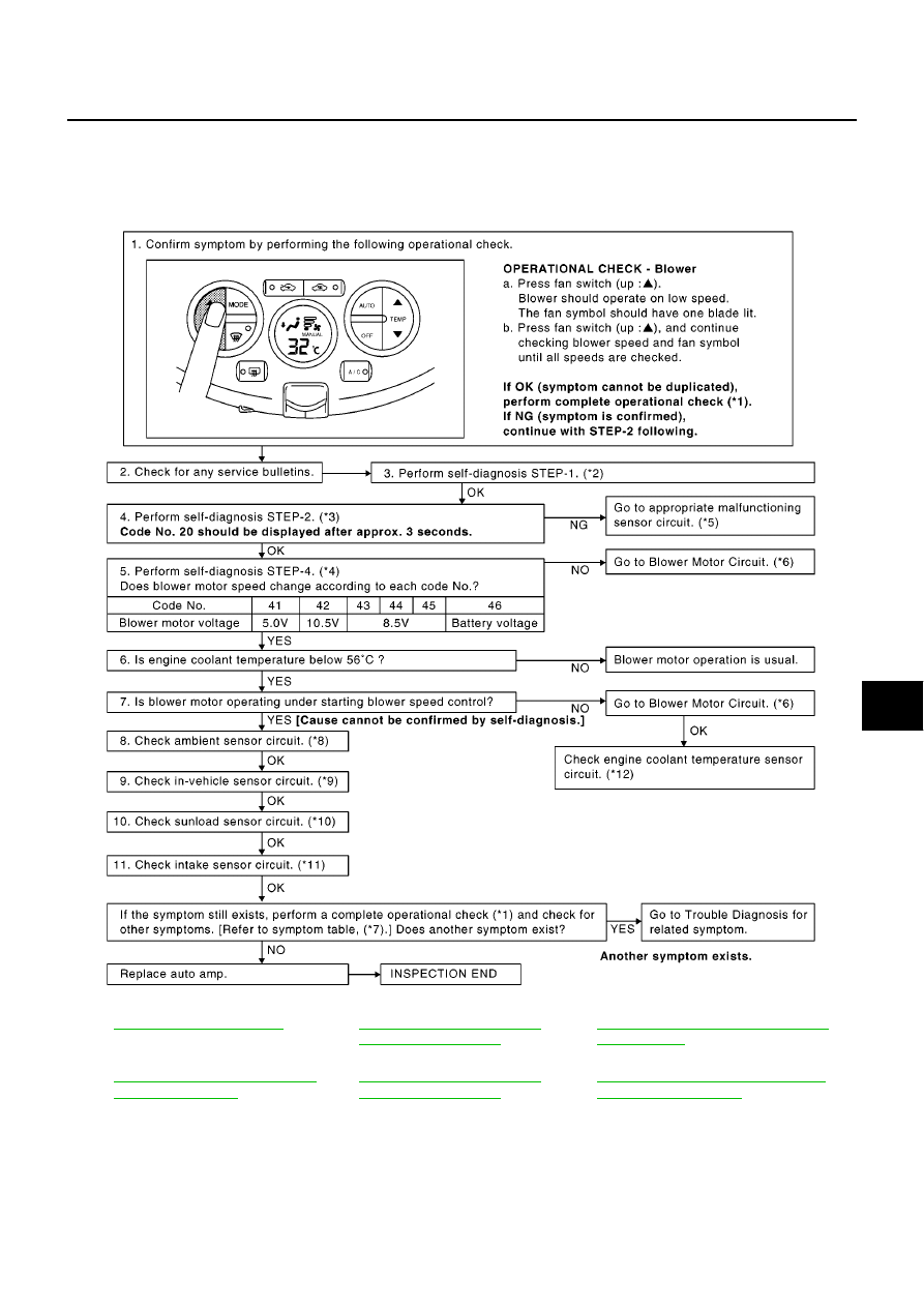
TROUBLE DIAGNOSIS
ATC-71
C
D
E
F
G
H
I
K
L
M
A
B
ATC
Blower Motor Circuit
BJS000BI
SYMPTOM: Blower motor operation is malfunctioning.
INSPECTION FLOW
*1
*2
ATC-48, "FUNCTION CONFIR-
MATION PROCEDURE"
, see No.
1.
*3
ATC-48, "FUNCTION CONFIRMATION
PROCEDURE"
, see No. 5.
*4
ATC-48, "FUNCTION CONFIRMA-
TION PROCEDURE"
, see No. 7.
*5
ATC-48, "FUNCTION CONFIR-
MATION PROCEDURE"
, see No.
13.
*6
ATC-73, "DIAGNOSTIC PROCEDURE
FOR BLOWER MOTOR"
MJIB0394E
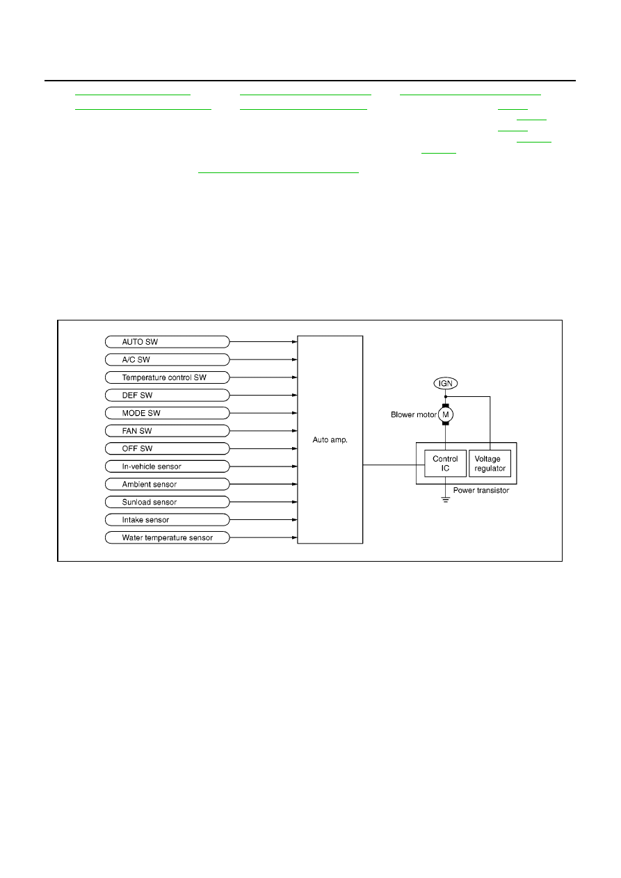
ATC-72
TROUBLE DIAGNOSIS
*For further information refer to
.
SYSTEM DESCRIPTION
Component Parts
Fan speed control system components are:
●
Auto amp.
●
In-vehicle sensor
●
Ambient sensor
●
Sunload sensor
●
Intake sensor
System Operation
Automatic Mode
In the automatic mode, the blower motor speed is calculated by the auto amp. based on input from in-vehicle
sensor, sunload sensor, intake sensor and ambient sensor.
The blower motor is applied voltage ranges from approximately 3.0 volts (lowest speed) to 12 volts (highest
speed).
The control blower speed (in the range of 3.0 to 12V), auto amp. supplies a gate voltage to the power transis-
tor. Based on this voltage, auto amp. controls voltage supplied to the blower motor.
Starting Fan Speed Control
Start up from COLD SOAK Condition (Automatic mode)
In a cold start up condition where the engine coolant temperature is below 56
°
C, the blower will not operate for
a short period of time (up to 150 seconds). The exact start delay time varies depending on the ambient and
engine coolant temperature.
In the most extreme case (very low ambient) the blower starting delay will be 150 seconds as described
above. After this delay, the blower will operate at low speed until the engine coolant temperature rises above
56
°
C, at which time the blower speed will increase to the objective speed.
Start up from usual or HOT SOAK Condition (Automatic mode)
*7
*8
ATC-99, "Ambient Sensor Circuit"
*9
ATC-102, "In-vehicle Sensor Circuit"
*10
ATC-105, "Sunload Sensor Circuit"
*11
ATC-108, "Intake Sensor Circuit"
*12 CR(WITH EURO–OBD):
CR(WITHOUT EURO–OBD):
HR(WITH EURO–OBD):
HR(WITHOUT EURO–OBD):
K9K:
MJIB0395E
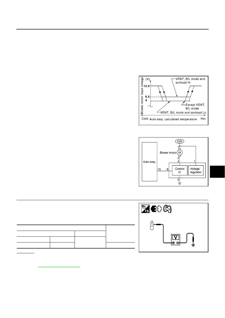
TROUBLE DIAGNOSIS
ATC-73
C
D
E
F
G
H
I
K
L
M
A
B
ATC
The blower will begin operation momentarily after the A/C switch is pushed. The blower speed will gradually
rise to the objective speed over a time period of 3 seconds or less (actual time depends on the objective
blower speed).
Blower Speed Compensation
Sunload
When the in-vehicle temperature and the set temperature are very close, the blower will be operating at low
speed. The low speed will vary depending on the sunload. During conditions of low or no sunload, the blower
low speed is usual low speed (approx. 4.0V). During high sunload conditions, auto amp. causes the blower
speed to increase (approx. 6.5V).
Fan Speed Control Specification
DIAGNOSTIC PROCEDURE FOR BLOWER MOTOR
SYMPTOM: Blower motor operation is malfunctioning.
1.
CHECK POWER SUPPLY FOR BLOWER MOTOR
1.
Disconnect blower motor connector.
2.
Turn ignition switch ON.
3.
Check voltage between blower motor harness connector and
ground.
OK or NG
OK
>> GO TO 2.
NG
>> Check power supply circuit and 15A fuses (Nos. 18 and 20, located in the fuse block). Refer to
.
●
If fuses are OK, check harness for open circuit. Repair or replace if necessary.
●
If fuses are OK, check blower relay. Replace if necessary.
●
If fuses are NG, replace fuse and check harness for short circuit. Repair or replace if necessary.
SJIA0792E
MJIB0396E
Terminals
Voltage
(Approx.)
(+)
(
−
)
Connector
Terminal
Ground
Blower motor: M56
1
Battery voltage
MJIB0516E
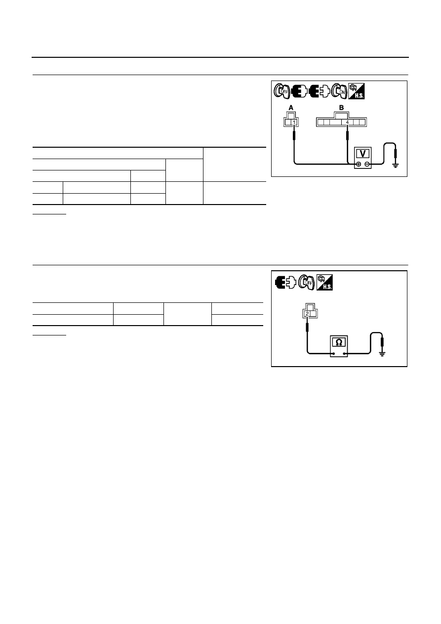
ATC-74
TROUBLE DIAGNOSIS
2.
CHECK CIRCUIT POWER SUPPLY FOR POWER TRANSISTOR
1.
Turn ignition switch OFF.
2.
Connect blower motor connector.
3.
Disconnect power transistor connector.
4.
Turn ignition switch ON.
5.
Check voltage between power transistor harness connector (A),
(B) and ground.
OK or NG
OK
>> GO TO 3.
NG
>>
●
Terminal 1 - Ground: Repair harness or connector.
●
Terminal 4 - Ground: GO TO 5.
3.
CHECK GROUND CIRCUIT FOR POWER TRANSISTOR
1.
Turn ignition switch OFF.
2.
Check continuity between power transistor harness connector
and ground.
OK or NG
OK
>> GO TO 4.
NG
>> Repair harness or connector.
Terminals
Voltage
(Approx.)
(+)
(
−
)
Connector
Terminal
A
Power transistor: M30
1
Ground
Battery voltage
B
Power transistor: M31
4
MJIB0397E
Connector
Terminal
Ground
Continuity
Power transistor: M30
2
Yes
MJIB0398E
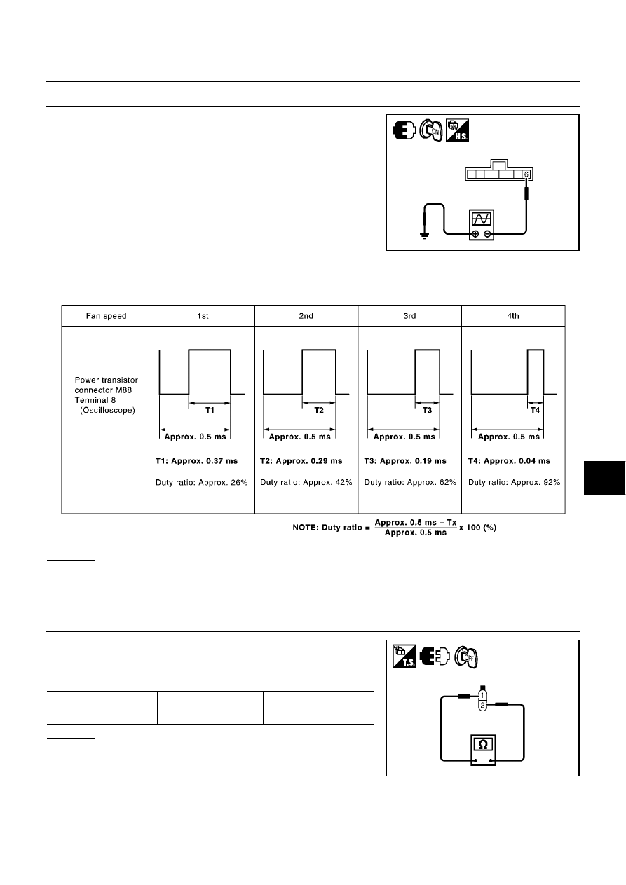
TROUBLE DIAGNOSIS
ATC-75
C
D
E
F
G
H
I
K
L
M
A
B
ATC
4.
CHECK FOR AUTO AMP. OUTPUT
1.
Reconnect power transistor connector.
2.
Turn ignition switch ON.
3.
Change the fan speed from Lo to Hi, and confirm the duty ratios between power transistor harness con-
nector and ground using an oscilloscope. Usual terminal 6 drive signal duty ratios are shown in the table
below.
OK or NG
OK
>> GO TO 5.
NG
>>
●
Fan speed is stuck at speed 4: GO TO 7.
●
Fan speed is stuck at speed 1: GO TO 8.
5.
CHECK BLOWER MOTOR
1.
Turn ignition switch OFF.
2.
Remove blower motor connector.
3.
Check continuity between blower motor connector terminals.
OK or NG
OK
>> GO TO 6.
NG
>> Replace blower motor.
MJIB0399E
SJIA0944E
Connector
Terminal
Continuity
Blower motor: M56
1
2
Yes
MJIB0517E
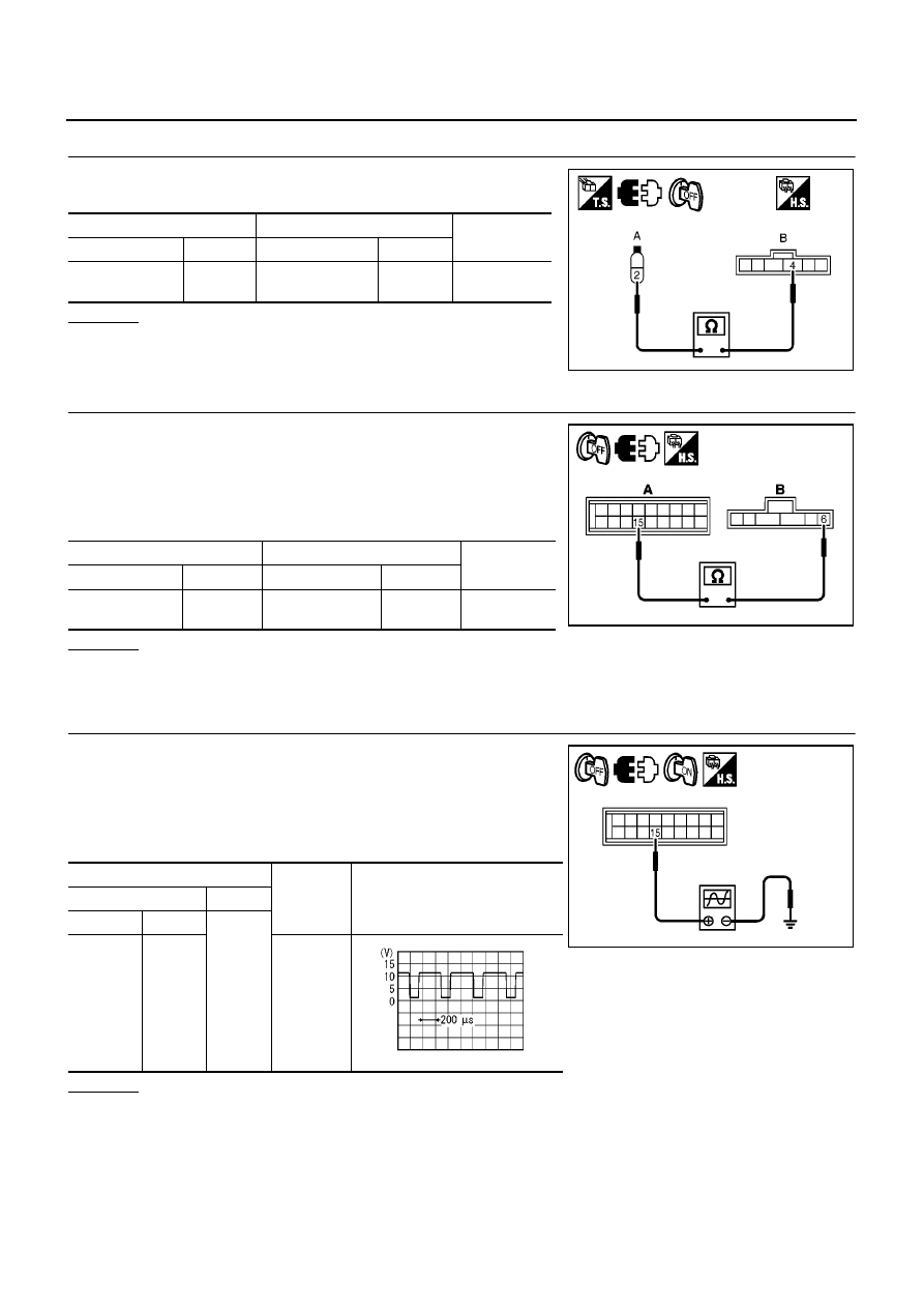
ATC-76
TROUBLE DIAGNOSIS
6.
CHECK CIRCUIT CONTINUITY BETWEEN BLOWER MOTOR AND POWER TRANSISTOR
Check continuity between blower motor harness connector (A) and
power transistor harness connector (B).
OK or NG
OK
>> GO TO 7.
NG
>> Repair harness or connector.
7.
CHECK CIRCUIT CONTINUITY BETWEEN AUTO AMP. AND POWER TRANSISTOR
1.
Turn ignition switch OFF.
2.
Disconnect power transistor connector.
3.
Disconnect auto amp. connector.
4.
Check continuity between auto amp. harness connector (A) and
power transistor harness connector (B).
OK or NG
OK
>> Replace power transistor.
NG
>> Repair harness or connector.
8.
CHECK FOR AUTO AMP. OUT PUT 2
1.
Turn ignition switch OFF.
2.
Disconnect auto amp. connector.
3.
Turn ignition switch ON.
4.
Check output signal between auto amp. harness connector and
ground.
OK or NG
OK
>> Replace auto amp.
NG
>> Replace power transistor.
A
B
Continuity
Connector
Terminal
Connector
Terminal
Blower motor:
M56
2
Power transistor:
M31
4
Yes
MJIB0518E
A
B
Continuity
Connector
Terminal
Connector
Terminal
Auto amp.: M64
15
Power transistor:
M31
6
Yes
MJIB0401E
Terminals
Condition
Voltage
(Approx.)
(+)
(
−
)
Connector
Terminal
Ground
Auto
amp.:
M64
15
Fan speed:
1st
MJIB0402E
ZJIA0863J
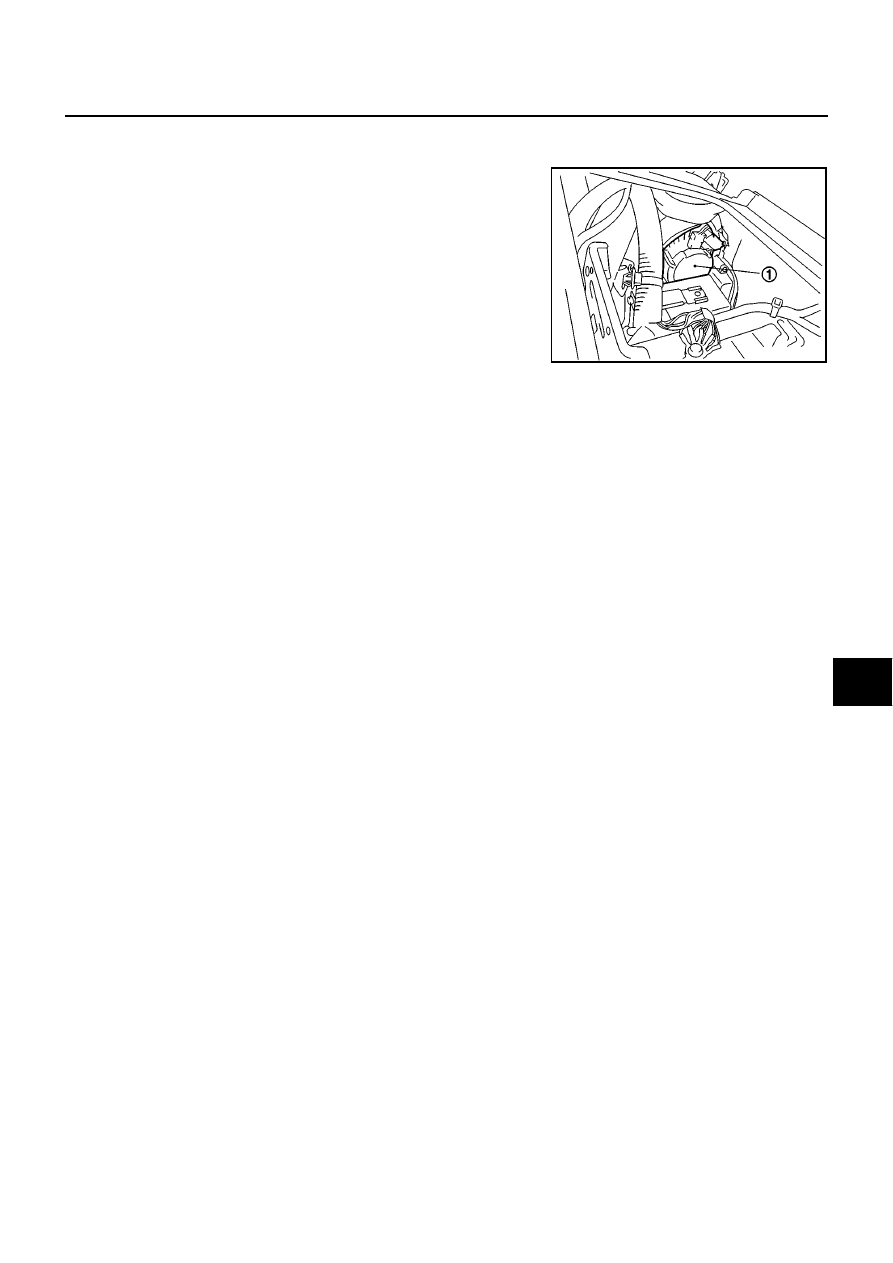
TROUBLE DIAGNOSIS
ATC-77
C
D
E
F
G
H
I
K
L
M
A
B
ATC
COMPONENT INSPECTION
Blower Motor
Confirm smooth rotation of the blower motor (1).
●
Ensure that there are no foreign particles inside the A/C unit
assembly.
SJIA0735E
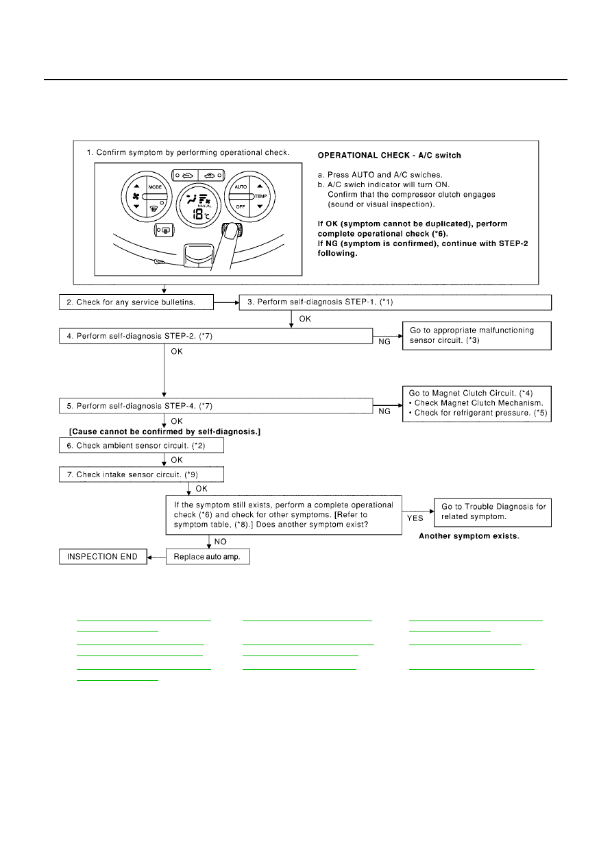
ATC-78
TROUBLE DIAGNOSIS
Magnet Clutch Circuit
BJS000BJ
SYMPTOM: Magnet clutch does not engage.
INSPECTION FLOW
*1
ATC-48, "FUNCTION CONFIRMA-
TION PROCEDURE"
, see No. 1.
*2
ATC-99, "Ambient Sensor Circuit"
*3
ATC-48, "FUNCTION CONFIRMA-
TION PROCEDURE"
, see No. 13.
*4
ATC-79, "DIAGNOSTIC PROCE-
DURE FOR MAGNET CLUTCH"
*5
ATC-91, "TROUBLE DIAGNOSIS
FOR UNUSUAL PRESSURE"
*6
*7
ATC-48, "FUNCTION CONFIRMA-
TION PROCEDURE"
, see No. 5 to 7.
*8
*9
ATC-108, "Intake Sensor Circuit"
MJIB0403E
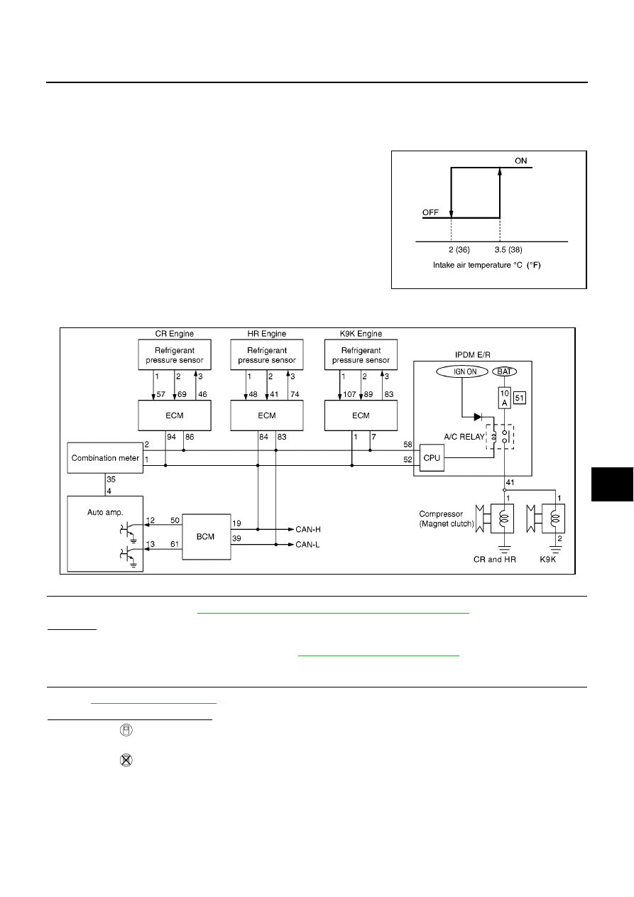
TROUBLE DIAGNOSIS
ATC-79
C
D
E
F
G
H
I
K
L
M
A
B
ATC
SYSTEM DESCRIPTION
Auto amp. controls compressor operation by intake air temperature and signal from ECM.
Low Temperature Protection Control
Auto amp. will turn compressor ON or OFF as determined by a signal detected by intake sensor.
When intake air temperatures are higher than 3.5
°
C (38
°
F), the com-
pressor turns ON. The compressor turns OFF when intake air tem-
peratures are lower than 2
°
C (36
°
F).
DIAGNOSTIC PROCEDURE FOR MAGNET CLUTCH
SYMPTOM: Magnet clutch does not engage when A/C switch is ON.
1.
CHECK INTAKE SENSOR CIRCUIT
Check intake sensor. Refer to
ATC-48, "FUNCTION CONFIRMATION PROCEDURE"
, see No. 12.
OK or NG
OK
>> GO TO 2.
NG
>> Malfunctioning intake sensor: Refer to
ATC-108, "Intake Sensor Circuit"
.
2.
PERFORM AUTO ACTIVE TEST
Refer to
.
Does the magnet clutch operate?
YES
>>
●
WITH CONSULT-II
GO TO 6.
●
WITHOUT CONSULT-II
GO TO 7.
NO
>> GO TO 3.
SJIA0802E
MJIB0404E
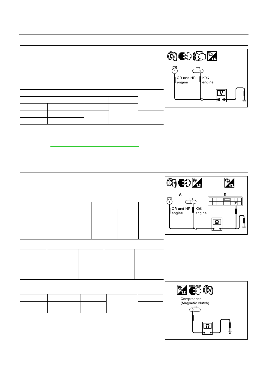
ATC-80
TROUBLE DIAGNOSIS
3.
CHECK POWER SUPPLY COMPRESSOR
1.
Turn ignition switch OFF.
2.
Disconnect compressor connector.
3.
Start the engine.
4.
Press AUTO switch and A/C switch ON.
5.
Check voltage between compressor harness connector and
ground.
OK or NG
OK
>> GO TO 5.
NG
>> Check power supply circuit and 10A fuse (No. 51, located in the fuse block), and GO TO 4. Refer
to
PG-32, "IPDM E/R Terminal Arrangement"
.
●
If fuse is OK, GO TO 4.
●
If fuse is NG, replace fuse and GO TO 4.
4.
CHECK CIRCUIT CONTINUITY BETWEEN IPDM E/R AND COMPRESSOR
1.
Turn ignition switch OFF.
2.
Disconnect IPDM E/R connector.
3.
Check continuity between compressor harness connector (A)
and IPDM E/R harness connector (B).
4.
Check continuity between compressor harness connection (A) and ground.
5.
Check continuity between compressor harness connector and
ground.
OK or NG
OK
>> GO TO 5.
NG
>> Repair harness or connector.
Terminals
Voltage
(Approx.)
(+)
(
−
)
Engine
Connector
Terminal
Ground
CR and HR
Compressor: F28
1
12V
K9K
Compressor: F129
MJIB0405E
A
B
Continuity
Engine
Connector
Terminal
Connector
Terminal
Yes
CR and HR
Compressor:
F28
1
IPDM E/R:
E7
41
K9K
Compressor:
F129
Engine
Connector
Terminal
Ground
Continuity
CR and HR
Compressor:
F28
1
No
K9K
Compressor:
F129
Engine
Connector
Terminal
Ground
Continuity
K9K
Compressor:
F129
2
Yes
MJIB0406E
MJIA0205E
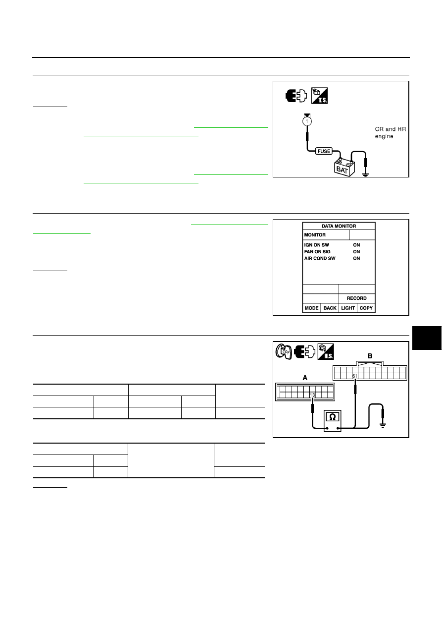
TROUBLE DIAGNOSIS
ATC-81
C
D
E
F
G
H
I
K
L
M
A
B
ATC
5.
CHECK MAGNET CLUTCH
Check for operation sound when applying battery voltage direct cur-
rent to terminal.
OK or NG
OK
>> 1. Replace IPDM E/R.
2. Go to self-diagnosis procedure
and perform self-
diagnosis STEP-4. Confirm that magnet clutch opera-
tion usual.
NG
>> 1. Replace compressor.
2. Go to self-diagnosis procedure
and perform self-
diagnosis STEP-4. Confirm that magnet clutch operation usual.
6.
CHECK BCM INPUT (COMPRESSOR ON) SIGNAL
Check compressor ON/OFF signal. Refer to
.
OK or NG
OK
>> GO TO 9.
NG
>> GO TO 7.
7.
CHECK CIRCUIT CONTINUITY BETWEEN AUTO AMP. AND BCM.
1.
Turn ignition switch OFF.
2.
Disconnect auto amp. harness connector.
3.
Check continuity between auto amp. harness connector (A) and
BCM harness connector.
4.
Check continuity between auto amp.harness connector (A) and
ground.
OK or NG
OK
>> GO TO 8.
NG
>> Repair harness or connector.
MJIB0407E
A/C SW ON
: AIR COND SW ON
A/C SW OFF
: AIR COND SW OFF
RJIA1111E
A
B
Continuity
Connector
Terminal
Connector
Terminal
Auto amp.: M64
13
BCM: M58
61
Yes
A
Ground
Continuity
Connector
Terminal
Auto amp.: M64
13
No
MJIB0408E
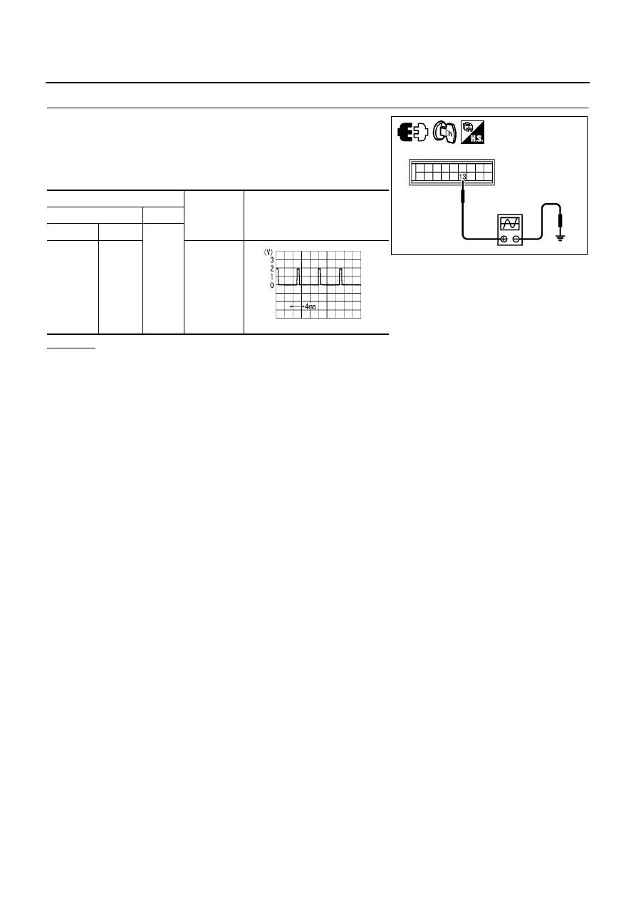
ATC-82
TROUBLE DIAGNOSIS
8.
CHECK VOLTAGE FOR AUTO AMP. (COMPRESSOR ON SIGNAL)
1.
Reconnect auto amp. harness connector and BCM harness con-
nector.
2.
Turn ignition switch ON.
3.
Confirm compressor ON signal between auto amp. harness con-
nector and ground.
OK or NG
OK
>> GO TO 9.
NG
>> Replace auto amp.
Terminals
Condition
Voltage
(Approx.)
(+)
(-)
Connector
Terminal
Ground
Auto
amp.: M64
13
A/C switch:
ON
(Blower
motor oper-
ates.)
MJIB0409E
ZJIA0584J
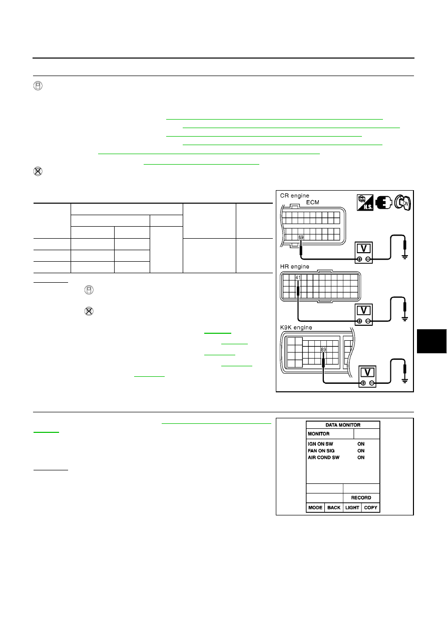
TROUBLE DIAGNOSIS
ATC-83
C
D
E
F
G
H
I
K
L
M
A
B
ATC
9.
CHECK REFRIGERANT PRESSURE SENSOR
WITH CONSULT-II
1.
Start the engine.
2.
Check the voltage of refrigerant pressure sensor.
CR(WITH EURO–OBD): Refer to
EC-112, "CONSULT-II Reference Value in Data Monitor Mode"
.
CR(WITHOUT EURO–OBD): Refer to
EC-527, "CONSULT-II Reference Value in Data Monitor Mode"
.
HR(WITH EURO–OBD): Refer to
EC-902, "CONSULT-II Reference Value in Data Monitor"
.
HR(WITHOUT EURO–OBD): Refer to
EC-1321, "CONSULT-II Reference Value in Data Monitor"
.
K9K: Refer to
EC-1694, "CONSULT-II Reference Value in Data Monitor Mode"
.
*For further information refer to
.
WITHOUT CONSULT-II
1.
Start the engine.
2.
Check voltage between ECM harness connector and ground.
OK or NG
OK
>>
●
WITH CONSULT-II
GO TO 10.
●
WITHOUT CONSULT-II
GO TO 11.
NG
>>
●
CR (WITH EURO–OBD): Refer to
.
●
CR (WITHOUT EURO–OBD): Refer to
.
●
HR (WITH EURO–OBD): Refer to
.
●
HR (WITHOUT EURO–OBD): Refer to
.
●
K9K: Refer to
.
10.
CHECK BCM INPUT (FAN ON) SIGNAL
Check FAN ON/OFF signal. Refer to
.
OK or NG
OK
>> GO TO 13.
NG
>> GO TO 11.
Engine
Terminals
Condition
Voltage
(Approx.)
(+)
(-)
Connector
Terminal
Ground
CR
ECM: F2
69
A/C switch: ON
(Blower motor
operates.)
1-4V
HR
ECM: F51
41
K9K
ECM: F134
89
MJIB0410E
FAN SW ON
: FAN ON SIG ON
FAN SW OFF
: FAN ON SIG OFF
RJIA1111E
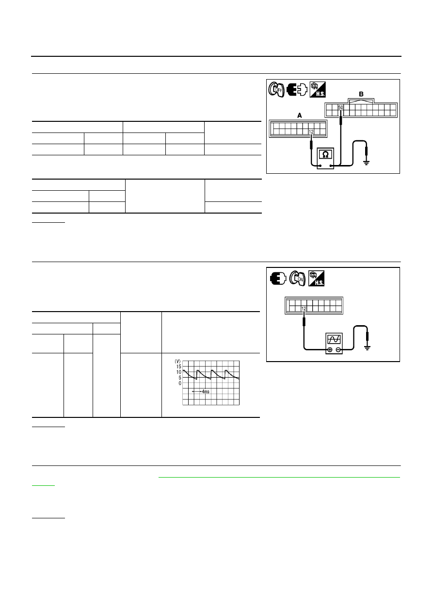
ATC-84
TROUBLE DIAGNOSIS
11.
CHECK CIRCUIT CONTINUITY BETWEEN AUTO AMP. AND BCM
1.
Turn ignition switch OFF.
2.
Disconnect auto amp. connector and BCM connector.
3.
Check continuity between auto amp. harness connector (A) and
BCM harness connector (B).
4.
Check continuity between auto amp.harness connector (A) and
ground.
OK or NG
OK
>> GO TO 12.
NG
>> Repair harness or connector.
12.
CHECK VOLTAGE FOR AUTO AMP. (FAN ON SIGNAL)
1.
Reconnect auto amp. connector and BCM connector.
2.
Turn ignition switch ON.
3.
Confirm fan ON signal between auto amp. harness connector
and ground using oscilloscope.
OK or NG
OK
>> Replace auto amp.
NG
>> Replace BCM.
13.
CHECK CAN COMMUNICATION
Check CAN communication. Refer to
BCS-17, "CAN Communication Inspection With CONSULT-II (Self-Diag-
.
●
BCM – ECM
●
ECM – IPDM E/R
OK or NG
OK
>> INSPECTION END
NG
>> Repair or replace malfunction part(s).
A
B
Continuity
Connector
Terminal
Connector
Terminal
Auto amp.: M64
12
BCM: M58
50
Yes
A
Ground
Continuity
Connector
Terminal
Auto amp.: M64
12
No
MJIB0411E
Terminals
Condition
Voltage
(Approx.)
(+)
(
−
)
Connec-
tor
Terminal
Ground
Auto
amp.:
M64
12
Fan speed:
1st
MJIB0412E
ZJIA0583J
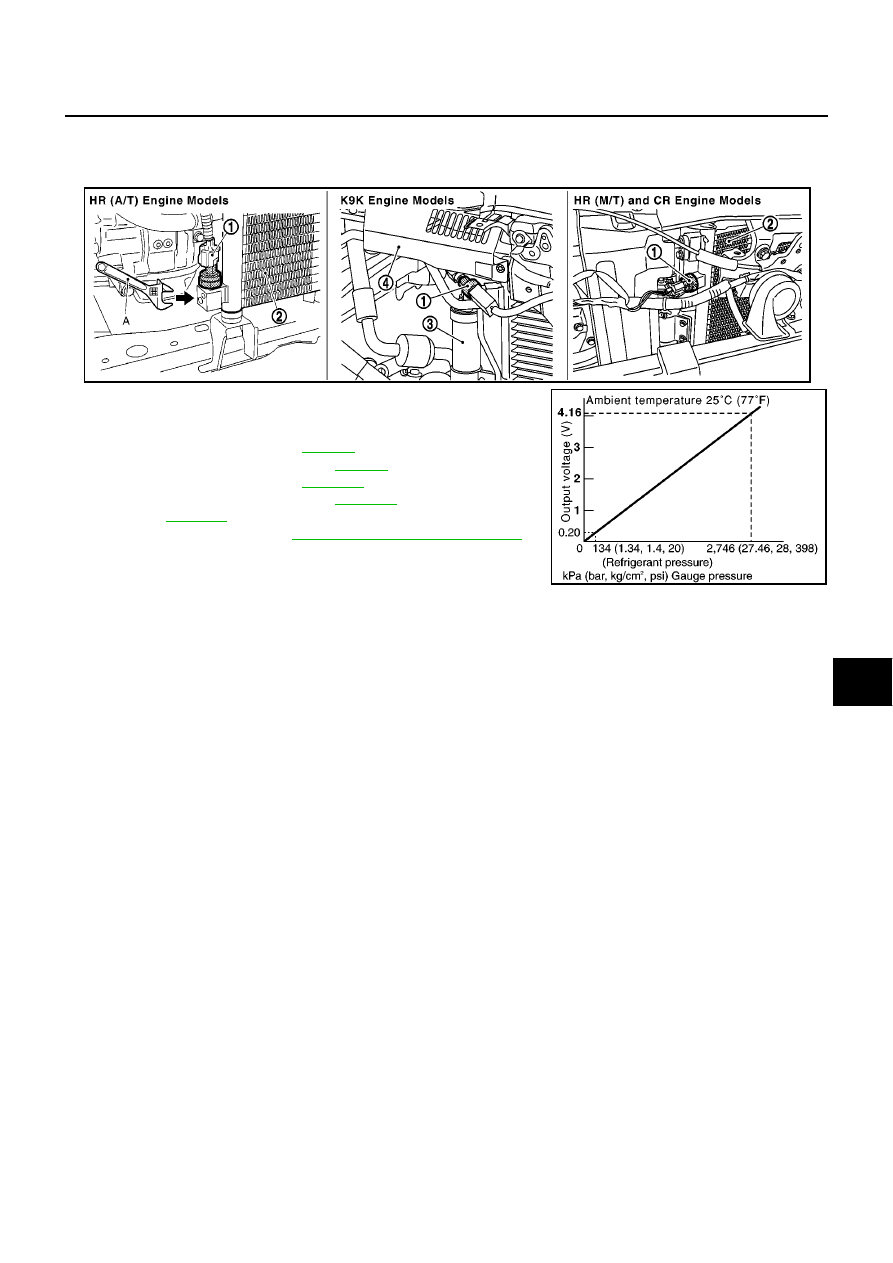
TROUBLE DIAGNOSIS
ATC-85
C
D
E
F
G
H
I
K
L
M
A
B
ATC
COMPONENT INSPECTION
Refrigerant Pressure Sensor
The refrigerant pressure sensor (1) is attached to the condenser.
Make sure that the A/C refrigerant pressure and the sensor output
voltage are within the specified range as shown in the A/C operating
condition figure.
CR(WITH EURO–OBD): Refer to
.
CR(WITHOUT EURO–OBD): Refer to
.
HR(WITH EURO–OBD): Refer to
.
HR(WITHOUT EURO–OBD): Refer to
.
K9K: Refer to
.
*For further information refer to
.
MJIB0457E
RJIA2954E
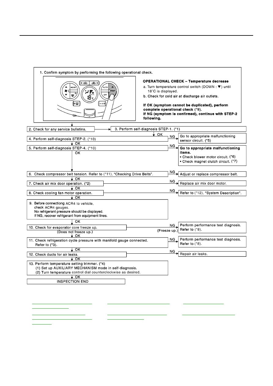
ATC-86
TROUBLE DIAGNOSIS
Insufficient Cooling
BJS000BK
SYMPTOM: Insufficient cooling
INSPECTION FLOW
*1
ATC-48, "FUNCTION CONFIRMA-
TION PROCEDURE"
, see No. 1.
*2
ATC-64, "Air Mix Door Motor Circuit"
*3
*4
ATC-54, "AUXILIARY MECHA-
NISM: TEMPERATURE SETTING
TRIMMER"
*5
ATC-48, "FUNCTION CONFIRMA-
TION PROCEDURE"
, see No. 13.
*6
ATC-71, "Blower Motor Circuit"
MJIB0413E

TROUBLE DIAGNOSIS
ATC-87
C
D
E
F
G
H
I
K
L
M
A
B
ATC
*For further information refer to
.
*7
ATC-78, "Magnet Clutch Circuit"
*8
ATC-88, "PERFORMANCE TEST
DIAGNOSIS"
*9
*10
ATC-48, "FUNCTION CONFIRMA-
TION PROCEDURE"
, see No. 5 to 7.
*11 CR:
HR:
EM-114, "Checking Drive Belts"
K9K:
*12 CR(WITH EURO–OBD):
CR(WITHOUT EURO–OBD):
HR(WITH EURO–OBD):
HR(WITHOUT EURO–OBD):
K9K:
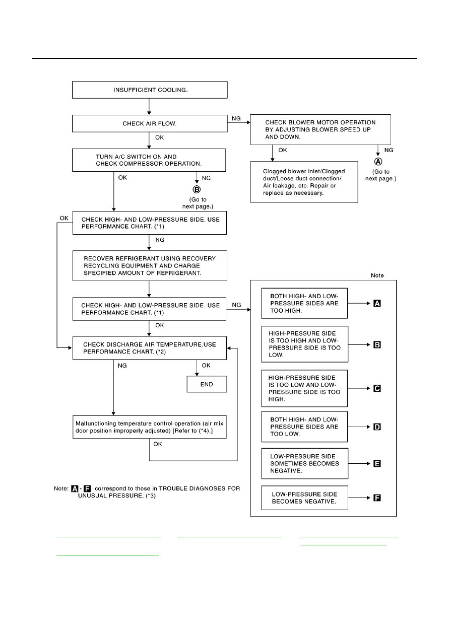
ATC-88
TROUBLE DIAGNOSIS
PERFORMANCE TEST DIAGNOSIS
*1
*2
*3
ATC-91, "TROUBLE DIAGNOSIS
FOR UNUSUAL PRESSURE"
*4
ATC-64, "Air Mix Door Motor Circuit"
RJIA1601E
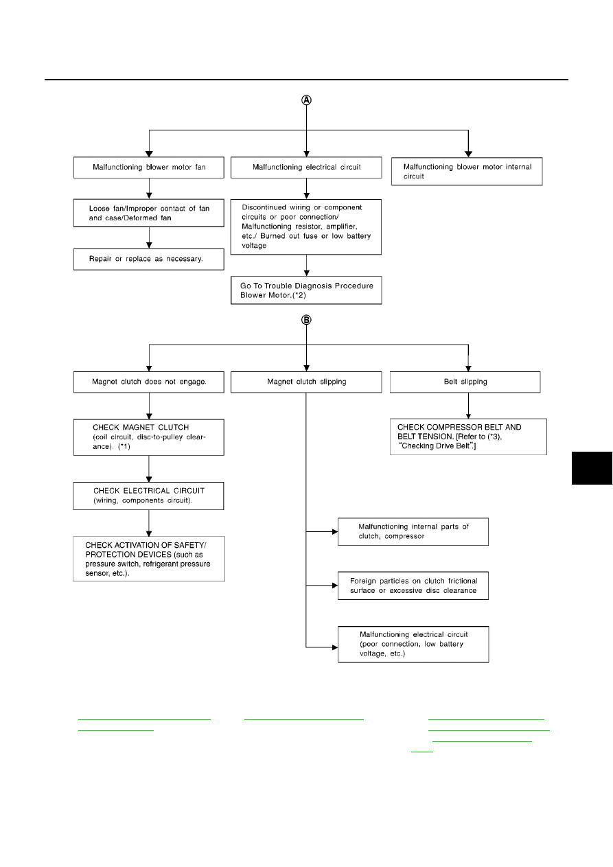
TROUBLE DIAGNOSIS
ATC-89
C
D
E
F
G
H
I
K
L
M
A
B
ATC
*1
ATC-141, "CHECK DISC TO PUL-
LEY CLEARANCE"
*2
ATC-71, "Blower Motor Circuit"
*3
CR:
HR:
EM-114, "Checking Drive Belts"
K9K:
RJIA3107E
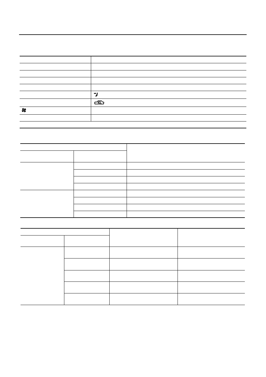
ATC-90
TROUBLE DIAGNOSIS
PERFORMANCE CHART
Test Condition
Testing must be performed as follows:
Test Reading
Recirculating-to-discharge Air Temperature Table
Ambient Air Temperature-to-operating Pressure Table
*1: In the motor fan low-speed control
*2: In the motor fan high-speed control
Vehicle condition
Indoors or in the shade (in a well-ventilated place)
Doors
Closed
Door window
Open
Hood
Open
TEMP.
Max. COLD
Mode switch
(Ventilation) set
Recirculation (REC) switch
(Recirculation) set
Fan (blower) speed
Max. speed set
Engine speed
Idle speed
Operate the air conditioning system for 10 minutes before taking measurements.
Inside air (Recirculating air) at blower assembly inlet
Discharge air temperature at center ventilator
°
C (
°
F)
Relative humidity
%
Air temperature
°
C (
°
F)
50 - 60
20 (68)
7.2 - 9.1 (45 - 48)
25 (77)
11.4 - 13.8 (53 - 57)
30 (86)
15.5 - 18.4 (60 - 65)
35 (95)
20.3 - 23.7 (69 - 75)
60 - 70
20 (68)
9.1 - 10.9 (48 - 52)
25 (77)
13.8 - 16.2 (57 - 61)
30 (86)
18.4 - 21.3 (65 - 70)
35 (95)
23.7 - 27.1 (75 - 81)
Ambient air
High-pressure (Discharge side)
kPa (bar, kg/cm
2
, psi)
Low-pressure (Suction side)
kPa (bar, kg/cm
2
, psi)
Relative humidity
%
Air temperature
°
C (
°
F)
50 - 70
20 (68)
843 - 1,036 *1
(11.08 - 13.63, 8.6 - 10.6, 122 - 150)
159.0 - 194.0
(1.59 - 1.94, 1.62 - 1.98, 23.1 - 28.1)
25 (77)
1,094 - 1,338 *1
(10.94 - 13.38, 11.2 - 13.6, 159 - 194)
196.3 - 240.0
(1.96 - 2.40, 2.00 - 2.45, 28.5 - 34.8)
30 (86)
1,298 - 1,590 *1
(12.98 - 15.90, 13.2 - 16.2, 188 - 231)
248.0 - 302.7
(2.48 - 3.03, 2.53 - 3.09, 36.0 - 43.9)
35 (95)
1,383 - 1,688 *2
(13.83 - 16.88, 14.1 - 17.2, 201 - 245)
308.8 - 377.4
(3.09 - 3.77, 3.15 - 3.85, 44.8 - 54.7)
40 (104)
1,628 - 1,988 *2
(16.28 - 19.88, 16.6 - 20.3, 236 - 288)
377.4 - 461.2
(3.77 - 4.61, 3.85 - 4.70, 54.7 - 66.8)
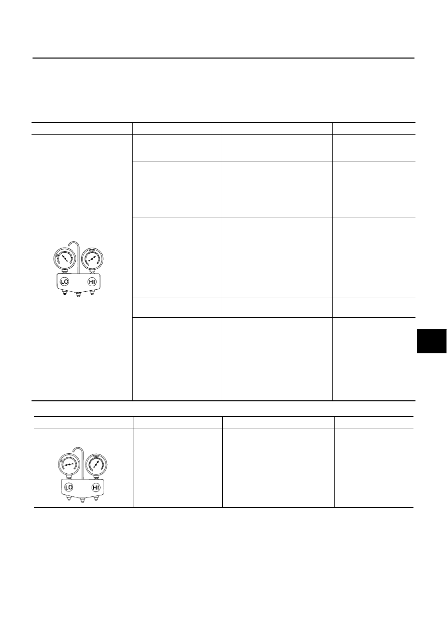
TROUBLE DIAGNOSIS
ATC-91
C
D
E
F
G
H
I
K
L
M
A
B
ATC
TROUBLE DIAGNOSIS FOR UNUSUAL PRESSURE
Whenever system’s high and/or low side pressure(s) is/are unusual, diagnose using a manifold gauge. The
marker above the gauge scale in the following tables indicates the standard (usual) pressure range. Since the
standard (usual) pressure, however, differs from vehicle, refer to above table (Ambient air temperature-to-
operating pressure table).
Both High- and Low-pressure Sides are Too High
High-pressure Side is Too High and Low-pressure Side is Too Low
Gauge indication
Refrigerant cycle
Probable cause
Corrective action
Both high- and low-pressure
sides are too high.
Pressure is reduced soon
after water is splashed on
condenser.
Excessive refrigerant charge in
refrigeration cycle.
Reduce refrigerant until
specified pressure is
obtained.
Air suction by cooling fan is
insufficient.
Insufficient condenser cooling perfor-
mance.
↓
1. Condenser fins are clogged.
2. Improper fan rotation of cooling
fan.
●
Clean condenser.
●
Check and repair cooling
fan if necessary.
●
Low-pressure pipe is not
cold.
●
When compressor is
stopped high-pressure
value quickly drops by
approximately 196 kPa
(1.96 bar, 2 kg/cm
2
, 28
psi). It then decreases
gradually thereafter.
Poor heat exchange in condenser
(After compressor operation stops,
high-pressure decreases too
slowly.).
↓
Air in refrigeration cycle.
Evacuate repeatedly and
recharge system.
Engine tends to overheat.
Engine cooling systems malfunction.
Check and repair each
engine cooling system.
●
An area of the low-pres-
sure pipe is colder than
areas near the evaporator
outlet.
●
Plates are sometimes cov-
ered with frost.
●
Excessive liquid refrigerant on low-
pressure side.
●
Excessive refrigerant discharge
flow.
●
Expansion valve is open a little
compared with the specification.
↓
Improper expansion valve adjust-
ment.
Replace expansion valve.
AC359A
Gauge indication
Refrigerant cycle
Probable cause
Corrective action
High-pressure side is too high
and low-pressure side is too low.
Upper side of condenser and
high-pressure side are hot,
however, liquid tank is not so
hot.
High-pressure tube or parts located
between compressor and condenser
are clogged or crushed.
●
Check and repair or
replace malfunctioning
parts.
●
Check lubricant for
contamination.
AC360A
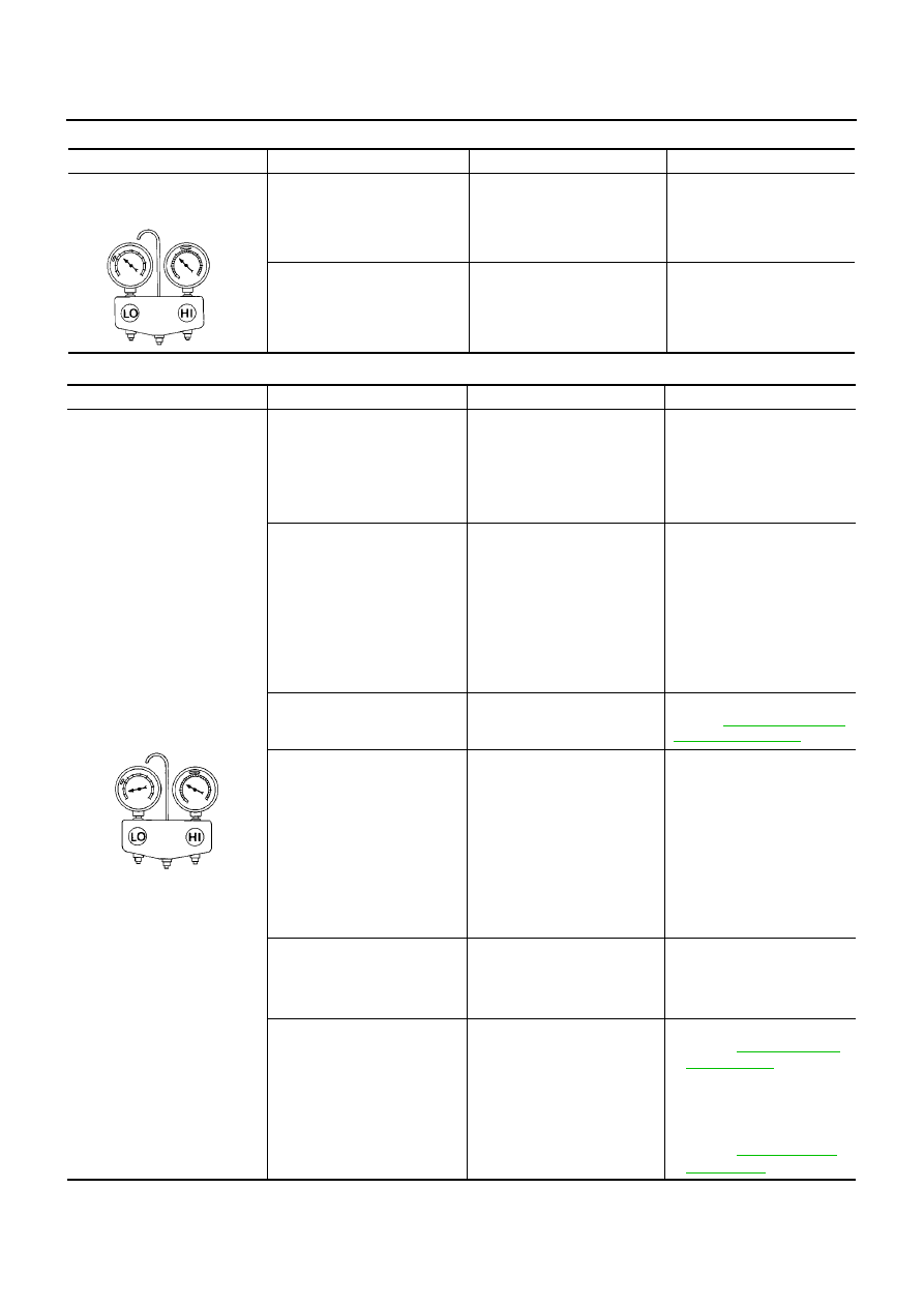
ATC-92
TROUBLE DIAGNOSIS
High-pressure Side is Too Low and Low-pressure Side is Too High
Both High- and Low-pressure Sides are Too Low
Gauge indication
Refrigerant cycle
Probable cause
Corrective action
High-pressure side is too low
and low-pressure side is too
high.
High- and low-pressure sides
become equal soon after com-
pressor operation stops.
Compressor pressure operation
is improper.
↓
Damaged inside compressor
packings.
Replace compressor.
No temperature difference
between high- and low-pres-
sure sides.
Compressor pressure operation
is improper.
↓
Damaged inside compressor
packings.
Replace compressor.
AC356A
Gauge indication
Refrigerant cycle
Probable cause
Corrective action
Both high- and low-pressure
sides are too low.
●
There is a big temperature
difference between liquid tank
outlet and inlet. Outlet tem-
perature is extremely low.
●
Liquid tank inlet and expan-
sion valve are frosted.
Liquid tank inside is slightly
clogged.
●
Replace liquid tank.
●
Check lubricant for contami-
nation.
●
Temperature of expansion
valve inlet is extremely low as
compared with areas near liq-
uid tank.
●
Expansion valve inlet may be
frosted.
●
Temperature difference
occurs somewhere in high-
pressure side.
High-pressure pipe located
between liquid tank and expan-
sion valve is clogged.
●
Check and repair malfunc-
tioning parts.
●
Check lubricant for contami-
nation.
Expansion valve and liquid tank
are warm or only cool when
touched.
Low refrigerant charge.
↓
Leaking fittings or components
Check refrigerant for leaks.
Refer to
.
There is a big temperature dif-
ference between expansion
valve inlet and outlet while the
valve itself is frosted.
Expansion valve closes a little
compared with the specifica-
tion.
↓
1. Improper expansion valve
adjustment.
2. Malfunctioning expansion
valve.
3. Outlet and inlet may be
clogged.
●
Remove foreign particles by
using compressed air.
●
Replace expansion valve.
●
Check lubricant for contami-
nation.
An area of the low-pressure
pipe is colder than areas near
the evaporator outlet.
Low-pressure pipe is clogged or
crushed.
●
Check and repair malfunc-
tioning parts.
●
Check lubricant for contami-
nation.
Air flow volume is not enough or
is too low.
Evaporator is frozen.
●
Check intake sensor circuit.
Refer to
.
●
Replace compressor.
●
Repair evaporator fins.
●
Replace evaporator.
●
Refer to
.
AC353A
TROUBLE DIAGNOSIS
ATC-93
C
D
E
F
G
H
I
K
L
M
A
B
ATC
Low-pressure Side Sometimes Becomes Negative
Low-pressure Side Becomes Negative
Gauge indication
Refrigerant cycle
Probable cause
Corrective action
Low-pressure side sometimes
becomes negative.
●
Air conditioning system
does not function and does
not cyclically cool the com-
partment air.
●
The system constantly func-
tions for a certain period of
time after compressor is
stopped and restarted.
Refrigerant does not dis-
charge cyclically.
↓
Moisture is frozen at expan-
sion valve outlet and inlet.
↓
Water is mixed with refriger-
ant.
●
Drain water from refrigerant
or replace refrigerant.
●
Replace liquid tank.
AC354A
Gauge indication
Refrigerant cycle
Probable cause
Corrective action
Low-pressure side becomes nega-
tive.
Liquid tank or front/rear side of
expansion valve’s pipe is
frosted or dewed.
High-pressure side is closed
and refrigerant does not flow.
↓
Expansion valve or liquid tank
is frosted.
Leave the system at rest until
no frost is present. Start it
again to check whether or not
the malfunction is caused by
water or foreign particles.
●
If water is the cause, initially
cooling is okay. Then the
water freezes causing a
blockage. Drain water from
refrigerant or replace refrig-
erant.
●
If due to foreign particles,
remove expansion valve
and remove the particles
with dry and compressed air
(not shop air).
●
If either of the above meth-
ods cannot correct the mal-
function, replace expansion
valve.
●
Replace liquid tank.
●
Check lubricant for contami-
nation.
AC362A
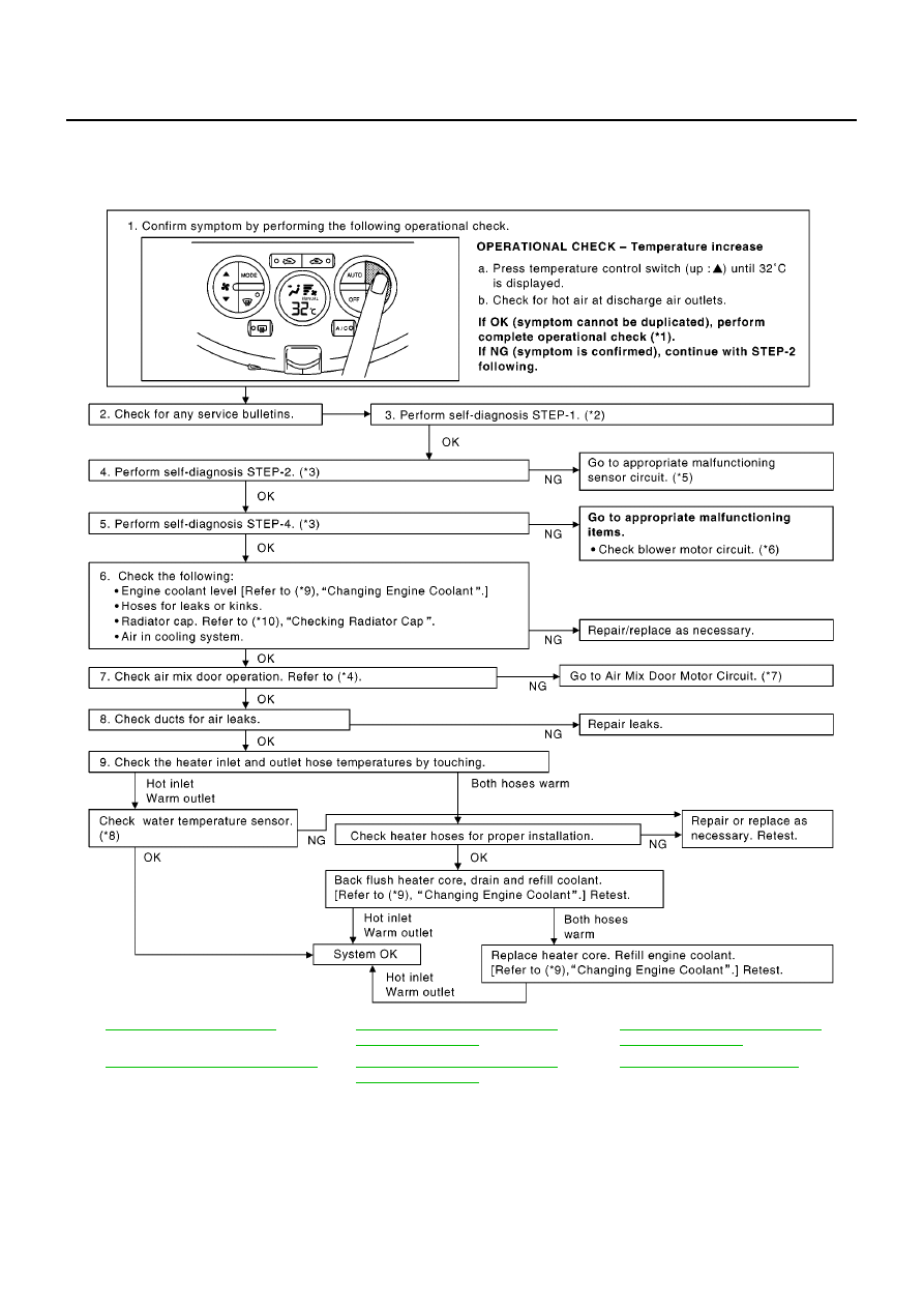
ATC-94
TROUBLE DIAGNOSIS
Insufficient Heating
BJS000BL
SYMPTOM: Insufficient heating
INSPECTION FLOW
*1
*2
ATC-48, "FUNCTION CONFIRMA-
TION PROCEDURE"
, see No. 1.
*3
ATC-48, "FUNCTION CONFIRMA-
TION PROCEDURE"
, see No. 5 to 7.
*4
ATC-64, "Air Mix Door Motor Circuit"
*5
ATC-48, "FUNCTION CONFIRMA-
TION PROCEDURE"
, see No. 13.
*6
ATC-71, "Blower Motor Circuit"
MJIB0414E

TROUBLE DIAGNOSIS
ATC-95
C
D
E
F
G
H
I
K
L
M
A
B
ATC
*For further information refer to
.
*7
ATC-64, "Air Mix Door Motor Circuit"
*8
CR(WITH EURO–OBD):
CR'WITHOUT EURO–OBD):
HR(WITH EURO–OBD):
HR(WITHOUT EURO–OBD):
K9K:
*9
CR:
HR:
K9K:
*10 CR:
or
HR:
or
K9K:
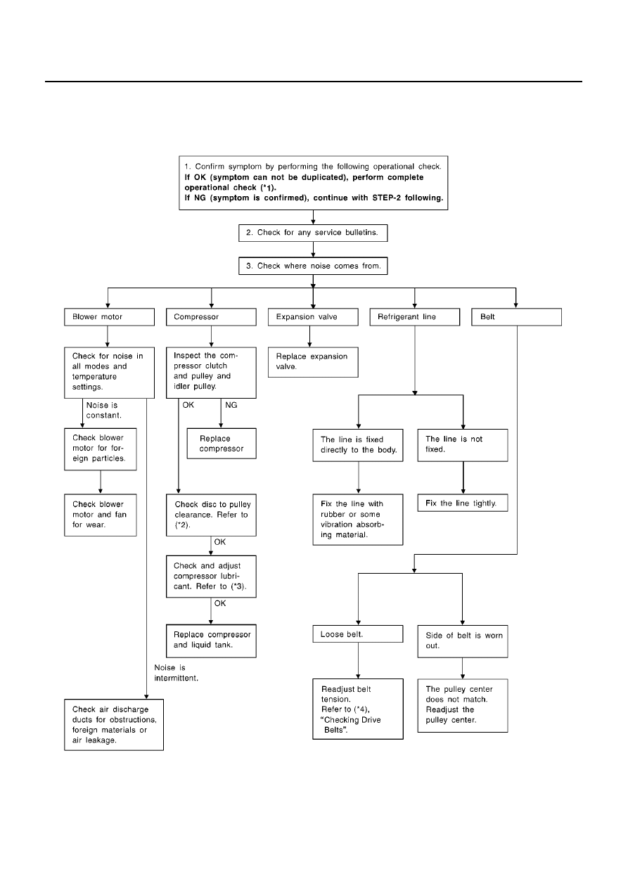
ATC-96
TROUBLE DIAGNOSIS
Noise
BJS000BM
SYMPTOM: Noise
INSPECTION FLOW
SJIA0843E
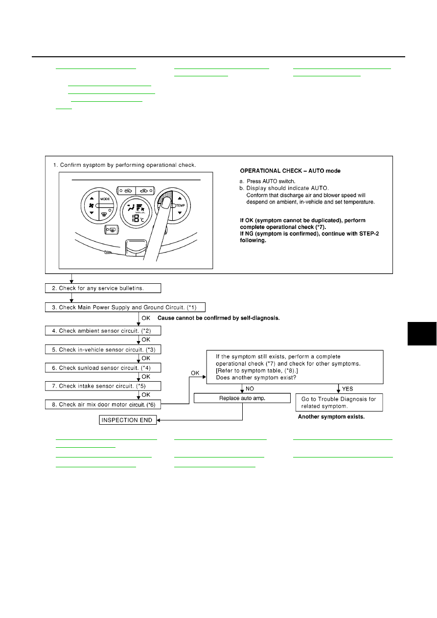
TROUBLE DIAGNOSIS
ATC-97
C
D
E
F
G
H
I
K
L
M
A
B
ATC
Self-diagnosis
BJS000BN
SYMPTOM: Self-diagnosis cannot be performed.
INSPECTION FLOW
*1
*2
ATC-141, "CHECK DISC TO PUL-
LEY CLEARANCE"
*3
ATC-17, "Maintenance of Lubricant
Quantity in Compressor"
*4
CR:
HR:
EM-114, "Checking Drive Belts"
K9K:
*1
ATC-57, "Power Supply and Ground
Circuit for Auto Amp."
*2
ATC-99, "Ambient Sensor Circuit"
*3
ATC-102, "In-vehicle Sensor Circuit"
*4
ATC-105, "Sunload Sensor Circuit"
*5
ATC-108, "Intake Sensor Circuit"
*6
ATC-64, "Air Mix Door Motor Circuit"
*7
*8
MJIB0415E
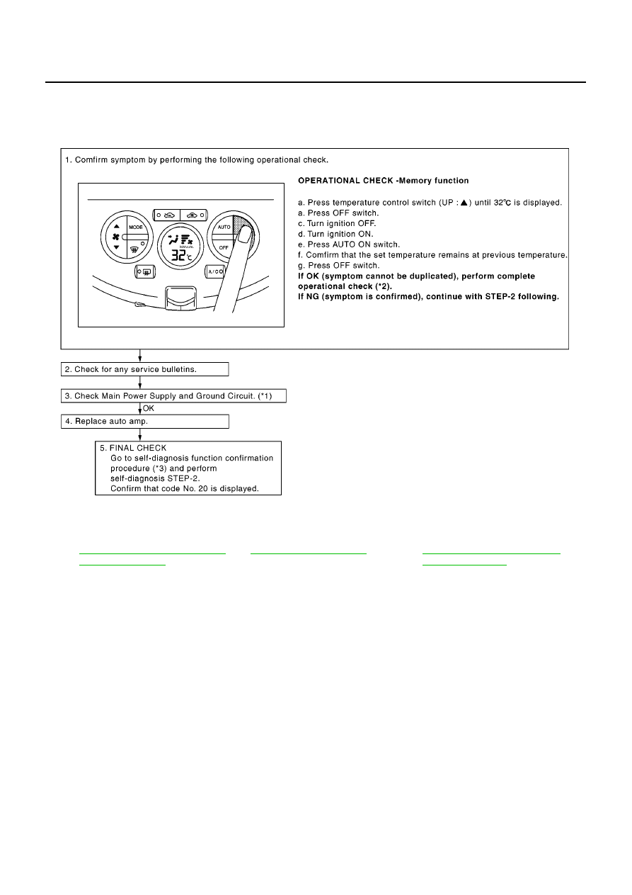
ATC-98
TROUBLE DIAGNOSIS
Memory Function
BJS000BO
SYMPTOM: Memory function does not operate.
INSPECTION FLOW
*1
ATC-57, "Power Supply and Ground
Circuit for Auto Amp."
*2
*3
ATC-48, "FUNCTION CONFIRMA-
TION PROCEDURE"
, see No. 5.
MJIB0416E
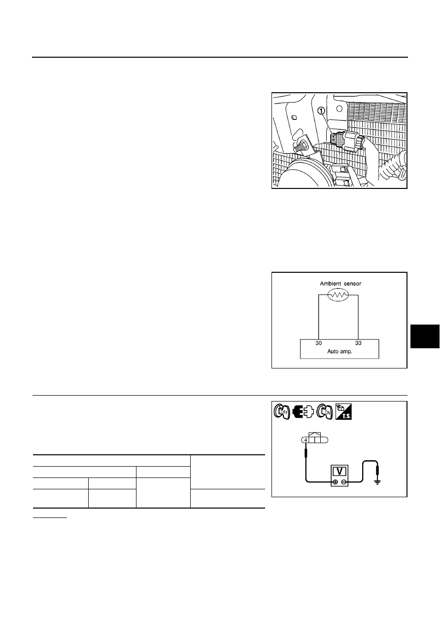
TROUBLE DIAGNOSIS
ATC-99
C
D
E
F
G
H
I
K
L
M
A
B
ATC
Ambient Sensor Circuit
BJS000BP
COMPONENT DESCRIPTION
Ambient Sensor
The ambient sensor (1) is attached on the radiator core support
upper. It detects ambient temperature and converts it into a resis-
tance value which is then input into the auto amp.
AMBIENT TEMPERATURE INPUT PROCESS
The auto amp. includes a processing circuit for the ambient sensor input. However, when the temperature
detected by the ambient sensor increases quickly, the processing circuit retards the auto amp. function. It only
allows the auto amp. to recognize an ambient temperature increase of 0.33
°
C (0.6
°
F) per 100 seconds.
As an example, consider stopping for a few minutes after high speed driving. Although the actual ambient tem-
perature has not changed, the temperature detected by the ambient sensor will increase. This is because the
heat from the engine compartment can radiate to the front grille area, location of the ambient sensor.
DIAGNOSTIC PROCEDURE FOR AMBIENT SENSOR
SYMPTOM: Ambient sensor circuit is open or shorted. (21 or
AUTO
21 is indicated on auto amp. As a result of performing self-diagnosis
STEP-2.)
1.
CHECK VOLTAGE BETWEEN AMBIENT SENSOR AND GROUND
1.
Turn ignition switch OFF.
2.
Disconnect ambient sensor connector.
3.
Turn ignition switch ON.
4.
Check voltage between ambient sensor harness connector and
ground.
OK or NG
OK
>> GO TO 2.
NG
>> GO TO 4.
MJIB0467E
SJIA0807E
Terminals
Voltage
(Approx.)
(+)
(
−
)
Connector
Terminal
Ground
Ambient sensor:
E17
4
5V
MJIB0417E
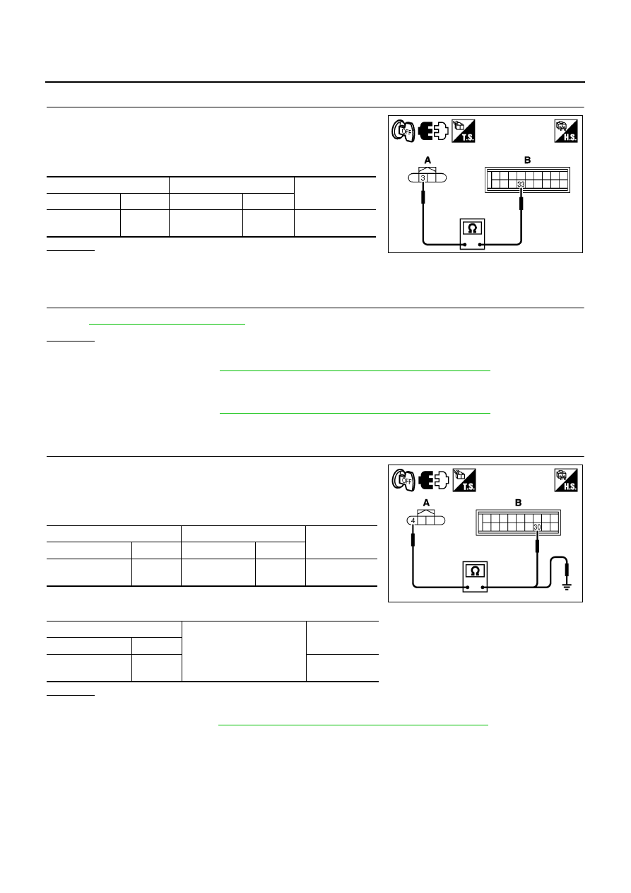
ATC-100
TROUBLE DIAGNOSIS
2.
CHECK CIRCUIT CONTINUITY BETWEEN AMBIENT SENSOR AND AUTO AMP.
1.
Turn ignition switch OFF.
2.
Disconnect auto amp. connector.
3.
Check continuity between ambient sensor harness connector
(A) and auto amp. harness connector (B).
OK or NG
OK
>> GO TO 3.
NG
>> Repair harness or connector.
3.
CHECK AMBIENT SENSOR
Refer to
.
OK or NG
OK
>> 1. Replace auto amp.
2. Go to self-diagnosis
ATC-48, "FUNCTION CONFIRMATION PROCEDURE"
and perform self-
diagnosis STEP-2. Confirm that code No. 20 is displayed.
NG
>> 1. Replace ambient sensor.
2. Go to self-diagnosis
ATC-48, "FUNCTION CONFIRMATION PROCEDURE"
and perform self-
diagnosis STEP-2. Confirm that code No. 20 is displayed.
4.
CHECK CIRCUIT CONTINUITY BETWEEN AMBIENT SENSOR AND AUTO AMP.
1.
Turn ignition switch OFF.
2.
Disconnect auto amp. connector.
3.
Check continuity between ambient sensor harness connector
(A) and auto amp. harness connector (B).
4.
Check continuity between ambient sensor harness connector
(A) and ground.
OK or NG
OK
>> 1. Replace auto amp.
2. Go to self-diagnosis
ATC-48, "FUNCTION CONFIRMATION PROCEDURE"
and perform self-
diagnosis STEP-2. Confirm that code No. 20 is displayed.
NG
>> Repair harness or connector.
A
B
Continuity
Connector
Terminal
Connector
Terminal
Ambient sensor:
E17
3
Auto amp.: M65
33
Yes
MJIB0418E
A
B
Continuity
Connector
Terminal
Connector
Terminal
Ambient sensor:
E17
4
Auto amp.: M65
30
Yes
A
Ground
Continuity
Connector
Terminal
Ambient sensor:
E17
4
No
MJIB0419E
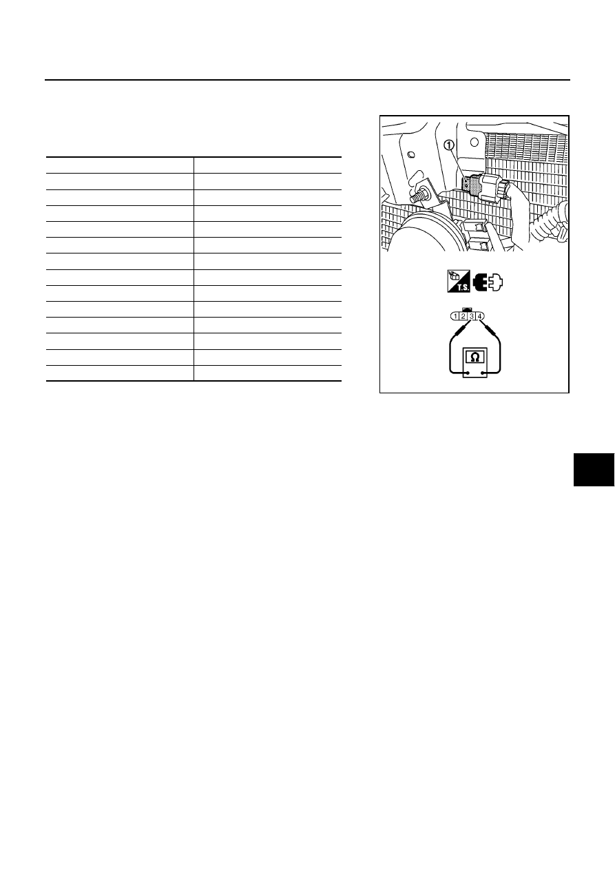
TROUBLE DIAGNOSIS
ATC-101
C
D
E
F
G
H
I
K
L
M
A
B
ATC
COMPONENT INSPECTION
Ambient Sensor
After disconnecting ambient sensor connector E32, measure resis-
tance between terminals 1 and 2 at sensor side, using the table
below.
If NG, replace ambient sensor.
Temperature
°
C (
°
F)
Resistance k
Ω
−
15 (5)
12.73
−
10 (14)
9.92
−
5 (23)
7.80
0 (32)
6.19
5 (41)
4.95
10 (50)
3.99
15 (59)
3.24
20 (68)
2.65
25 (77)
2.19
30 (86)
1.81
35 (95)
1.51
40 (104)
1.27
45 (113)
1.07
MJIB0468E
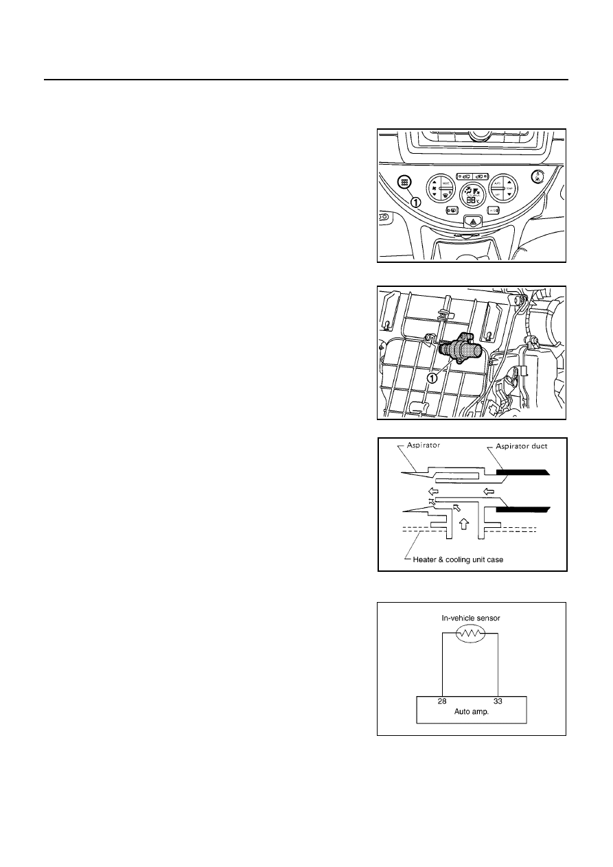
ATC-102
TROUBLE DIAGNOSIS
In-vehicle Sensor Circuit
BJS000BQ
COMPONENT DESCRIPTION
In-vehicle Sensor
The in-vehicle sensor (1) is located on instrument lower finisher. It
converts variations in temperature of compartment air drawn from
the aspirator into a resistance value. It is then input into the auto
amp.
Aspirator
The aspirator (1) is located on passenger’s side of A/C unit assem-
bly. It produces vacuum pressure due to air discharged from the A/C
unit, continuously taking compartment air in the aspirator.
DIAGNOSTIC PROCEDURE FOR IN-VEHICLE SENSOR
SYMPTOM: In-vehicle sensor circuit is open or shorted. (22 or
AUTO
22 is indicated on auto amp. as a result of performing self-diagnosis
STEP-2.)
MJIB0420E
MJIB0421E
RJIA1402E
SJIA0815E
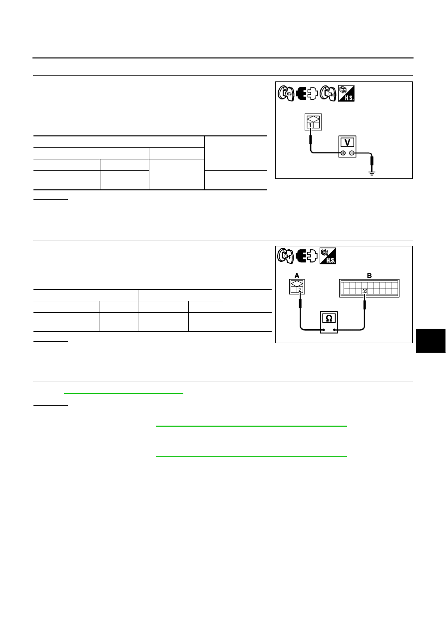
TROUBLE DIAGNOSIS
ATC-103
C
D
E
F
G
H
I
K
L
M
A
B
ATC
1.
CHECK VOLTAGE BETWEEN IN-VEHICLE SENSOR AND GROUND
1.
Turn ignition switch OFF.
2.
Disconnect in-vehicle sensor connector.
3.
Turn ignition switch ON.
4.
Check voltage between in-vehicle sensor harness connector
and ground.
OK or NG
OK
>> GO TO 2.
NG
>> GO TO 4.
2.
CHECK CIRCUIT CONTINUITY BETWEEN IN-VEHICLE SENSOR AND AUTO AMP.
1.
Turn ignition switch OFF.
2.
Disconnect auto amp. connector.
3.
Check continuity between in-vehicle sensor harness connector
(A) and auto amp. harness connector (B).
OK or NG
OK
>> GO TO 3.
NG
>> Repair harness or connector.
3.
CHECK IN-VEHICLE SENSOR
Refer to
.
OK or NG
OK
>> 1. Replace auto amp.
2. Go to self-diagnosis
ATC-48, "FUNCTION CONFIRMATION PROCEDURE"
and perform self-
diagnosis STEP-2. Confirm that code No. 20 is displayed.
NG
>> 1. Replace in-vehicle sensor.
2. Go to self-diagnosis
ATC-48, "FUNCTION CONFIRMATION PROCEDURE"
and perform self-
diagnosis STEP-2. Confirm that code No. 20 is displayed.
Terminals
Voltage
(Approx.)
(+)
(
−
)
Connector
Terminal
Ground
In-vehicle sensor:
M43
1
5V
SJIA0816E
A
B
Continuity
Connector
Terminal
Connector
Terminal
In-vehicle sensor:
M43
2
Auto amp.: M65
33
Yes
MJIB0422E
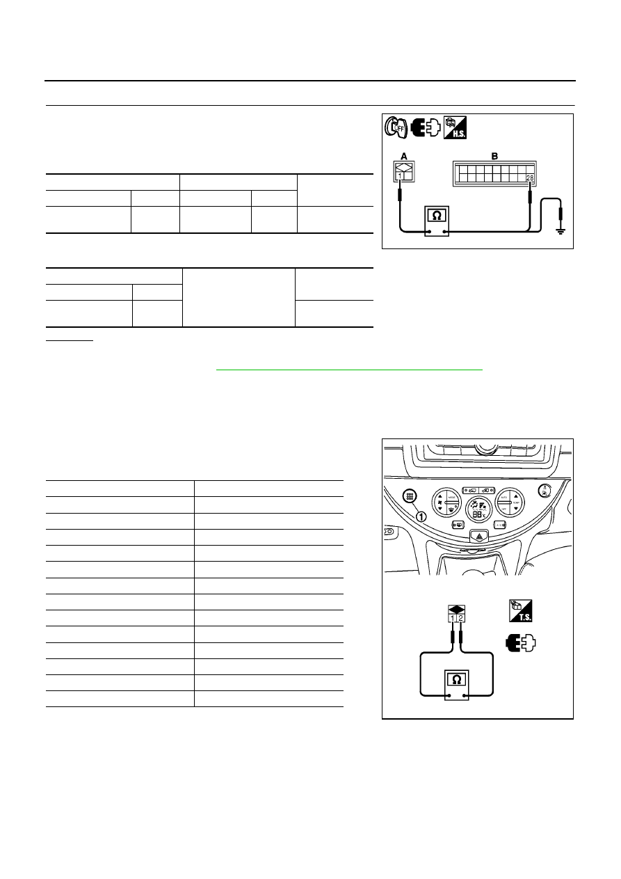
ATC-104
TROUBLE DIAGNOSIS
4.
CHECK CIRCUIT CONTINUITY BETWEEN IN-VEHICLE SENSOR AND AUTO AMP.
1.
Turn ignition switch OFF.
2.
Disconnect auto amp. connector.
3.
Check continuity between in-vehicle sensor harness connector
(A) and auto amp. harness connector (B).
4.
Check continuity between in-vehicle sensor harness connector
(A) and ground.
OK or NG
OK
>> 1. Replace auto amp.
2. Go to self-diagnosis
ATC-48, "FUNCTION CONFIRMATION PROCEDURE"
and perform self-
diagnosis STEP-2. Confirm that code No. 20 is displayed.
NG
>> Repair harness or connector.
COMPONENT INSPECTION
In-vehicle Sensor
After disconnecting in-vehicle sensor connector M41, measure resis-
tance between terminals 1 and 2 at sensor side, using the table
below.
If NG, replace in-vehicle sensor.
A
B
Continuity
Connector
Terminal
Connector
Terminal
In-vehicle sensor:
M43
1
Auto amp.: M65
28
Yes
A
Ground
Continuity
Connector
Terminal
In-vehicle sensor:
M43
1
No
MJIB0423E
Temperature
°
C (
°
F)
Resistance k
Ω
−
15 (5)
12.73
−
10 (14)
9.92
−
5 (23)
7.80
0 (32)
6.19
5 (41)
4.95
10 (50)
3.99
15 (59)
3.24
20 (68)
2.65
25 (77)
2.19
30 (86)
1.81
35 (95)
1.51
40 (104)
1.27
45 (113)
1.07
MJIB0424E
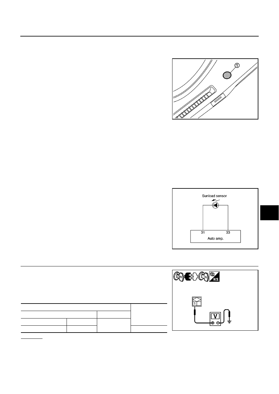
TROUBLE DIAGNOSIS
ATC-105
C
D
E
F
G
H
I
K
L
M
A
B
ATC
Sunload Sensor Circuit
BJS000BR
COMPONENT DESCRIPTION
Sunload Sensor
The sunload sensor (1) is located on the instrument upper mask. It
detects sunload entering through windshield by means of a photo
diode. The sensor converts the sunload into a current value which is
then input into the auto amp.
SUNLOAD INPUT PROCESS
The auto amp. also includes a processing circuit which averages the variations in detected sunload over a
period of time. This prevents drastic swings in the ATC system operation due to small or quick variations in
detected sunload.
For example, consider driving along a road bordered by an occasional group of large trees. The sunload
detected by the sunload sensor will vary whenever the trees obstruct the sunlight. The processing circuit aver-
ages the detected sunload over a period of time, so that the (insignificant) effect of the trees momentarily
obstructing the sunlight does not cause any change in the ATC system operation. On the other hand, shortly
after entering a long tunnel, the system will recognize the change in sunload, and the system will react accord-
ingly.
DIAGNOSTIC PROCEDURE FOR SUNLOAD SENSOR
SYMPTOM: Sunload sensor circuit is open or shorted. (25 or
AUTO
25 is indicated on auto amp. as a result of performing self-diagnosis
STEP-2.)
1.
CHECK VOLTAGE BETWEEN SUNLOAD SENSOR AND GROUND
1.
Turn ignition switch OFF.
2.
Disconnect sunload sensor connector.
3.
Turn ignition switch ON.
4.
Check voltage between sunload sensor harness connector and
ground.
OK or NG
OK
>> GO TO 2.
NG
>> GO TO 4.
MJIB0431E
SJIA0820E
Terminals
Voltage
(Approx.)
(+)
(
−
)
Connector
Terminal
Ground
Sunload sensor: M23
1
5V
SJIA0821E
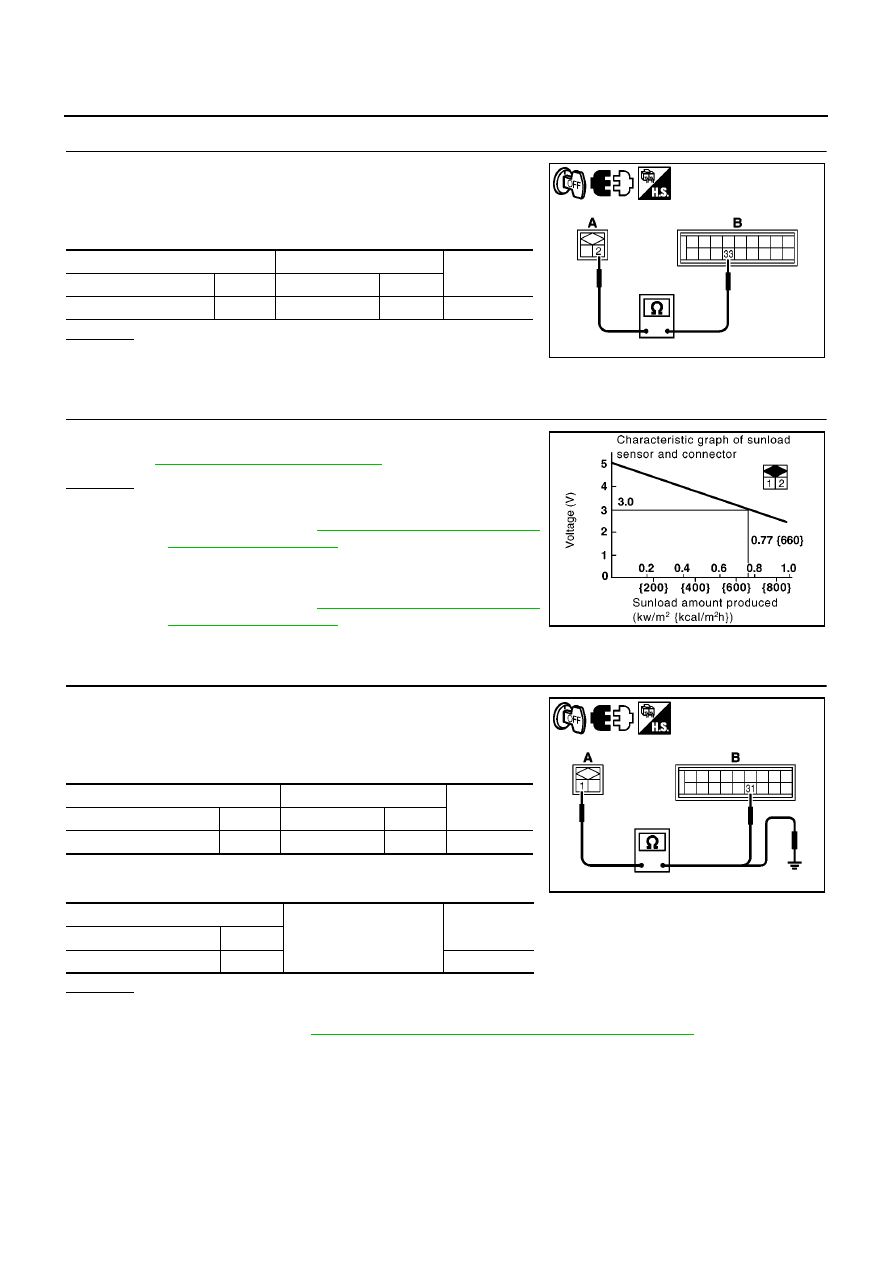
ATC-106
TROUBLE DIAGNOSIS
2.
CHECK CIRCUIT CONTINUITY BETWEEN SUNLOAD SENSOR AND AUTO AMP.
1.
Turn ignition switch OFF.
2.
Disconnect auto amp. connector.
3.
Check continuity between sunload sensor harness connector
(A) and auto amp. harness connector (B).
OK or NG
OK
>> GO TO 3.
NG
>> Repair harness or connector.
3.
CHECK SUNLOAD SENSOR
1.
Reconnect sunload sensor connector and auto amp. connector.
2.
Refer to
.
OK or NG
OK
>> 1. Replace auto amp.
2. Go to self-diagnosis
and perform self-diagnosis
STEP-2. Confirm that code No. 20 is displayed.
NG
>> 1. Replace sunload sensor.
2. Go to self-diagnosis
and perform self-diagnosis
STEP-2. Confirm that code No. 20 is displayed.
4.
CHECK CIRCUIT CONTINUITY BETWEEN SUNLOAD SENSOR AND AUTO AMP.
1.
Turn ignition switch OFF.
2.
Disconnect auto amp. connector.
3.
Check continuity between sunload sensor harness connector
(B) and auto amp. harness connector (B).
4.
Check continuity between sunload sensor harness connector
(A) and ground.
OK or NG
OK
>> 1. Replace auto amp.
2. Go to self-diagnosis
ATC-48, "FUNCTION CONFIRMATION PROCEDURE"
and perform self-
diagnosis STEP-2. Confirm that code No. 20 is displayed.
NG
>> Repair harness or connector.
A
B
Continuity
Connector
Terminal
Connector
Terminal
Sunload sensor: M23
2
Auto amp.: M65
33
Yes
MJIB0422E
MJIA0089E
A
B
Continuity
Connector
Terminal
Connector
Terminal
Sunload sensor: M23
1
Auto amp.: M65
31
Yes
A
Ground
Continuity
Connector
Terminal
Sunload sensor: M23
1
No
MJIB0425E
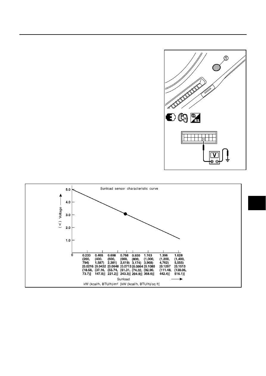
TROUBLE DIAGNOSIS
ATC-107
C
D
E
F
G
H
I
K
L
M
A
B
ATC
COMPONENT INSPECTION
Sunload Sensor
Measure voltage between auto amp. harness connector M65 termi-
nal 31 and ground.
If NG, replace sunload sensor (1).
●
When checking sunload sensor, select a place where sun shines directly on it.
MJIB0469E
SHA930E
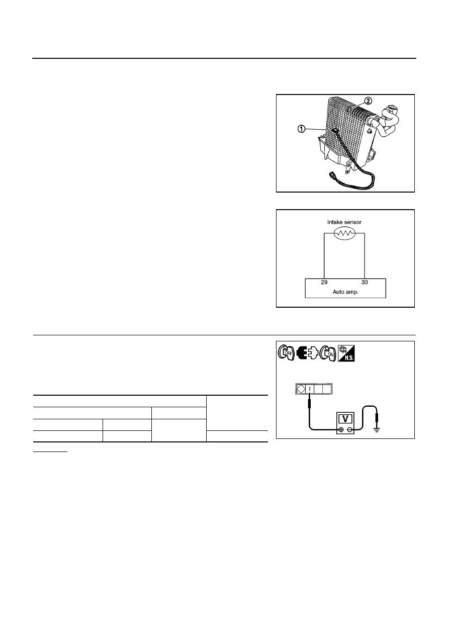
ATC-108
TROUBLE DIAGNOSIS
Intake Sensor Circuit
BJS000BS
COMPONENT DESCRIPTION
Intake Sensor
The intake sensor (1) is located on the A/C unit. It converts tempera-
ture of air that through the evaporator (2) into a resistance value
which is then input to the auto amp.
DIAGNOSTIC PROCEDURE FOR INTAKE SENSOR
SYMPTOM: Intake sensor circuit is open or shorted. (24 or
AUTO
24
is indicated on auto amp. as a result of performing self-diagnosis
STEP-2.)
1.
CHECK VOLTAGE BETWEEN INTAKE SENSOR AND GROUND
1.
Turn ignition switch OFF.
2.
Disconnect intake sensor connector.
3.
Turn ignition switch ON.
4.
Check voltage between intake sensor harness connector and
ground.
OK or NG
OK
>> GO TO 2.
NG
>> GO TO 4.
MJIB0459E
SJIA0824E
Terminals
Voltage
(Approx.)
(+)
(
−
)
Connector
Terminal
Ground
Intake sensor: M44
1
5V
SJIA0825E
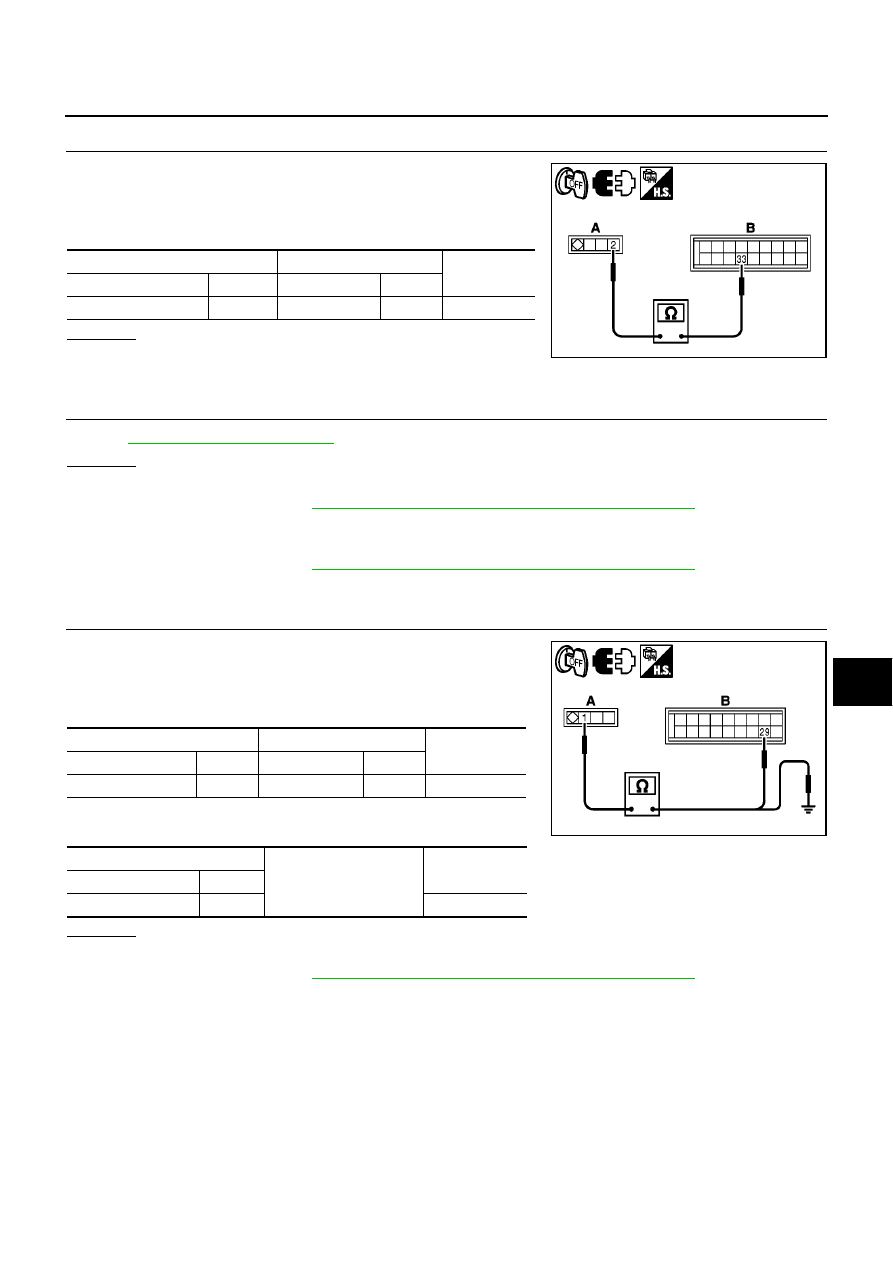
TROUBLE DIAGNOSIS
ATC-109
C
D
E
F
G
H
I
K
L
M
A
B
ATC
2.
CHECK CIRCUIT CONTINUITY BETWEEN INTAKE SENSOR AND AUTO AMP.
1.
Turn ignition switch OFF.
2.
Disconnect auto amp. connector.
3.
Check continuity between intake sensor harness connector (A)
and auto amp. harness connector (B).
OK or NG
OK
>> GO TO 3.
NG
>> Repair harness or connector.
3.
CHECK INTAKE SENSOR
Refer to
.
OK or NG
OK
>> 1. Replace auto amp.
2. Go to self-diagnosis
ATC-48, "FUNCTION CONFIRMATION PROCEDURE"
and perform self-
diagnosis STEP-2. Confirm that code No. 20 is displayed.
NG
>> 1. Replace intake sensor.
2. Go to self-diagnosis
ATC-48, "FUNCTION CONFIRMATION PROCEDURE"
and perform self-
diagnosis STEP-2. Confirm that code No. 20 is displayed.
4.
CHECK CIRCUIT CONTINUITY BETWEEN INTAKE SENSOR AND AUTO AMP.
1.
Turn ignition switch OFF.
2.
Disconnect auto amp. connector.
3.
Check continuity between intake sensor harness connector (A)
and auto amp. harness connector (B).
4.
Check continuity between intake sensor harness connector (A)
and ground.
OK or NG
OK
>> 1. Replace auto amp.
2. Go to self-diagnosis
ATC-48, "FUNCTION CONFIRMATION PROCEDURE"
and perform self-
diagnosis STEP-2. Confirm that code No. 20 is displayed.
NG
>> Repair harness or connector.
A
B
Continuity
Connector
Terminal
Connector
Terminal
Intake sensor: M44
2
Auto amp.: M65
33
Yes
MJIB0426E
A
B
Continuity
Connector
Terminal
Connector
Terminal
Intake sensor: M44
1
Auto amp.: M65
29
Yes
A
Ground
Continuity
Connector
Terminal
Intake sensor: M44
1
No
MJIB0427E
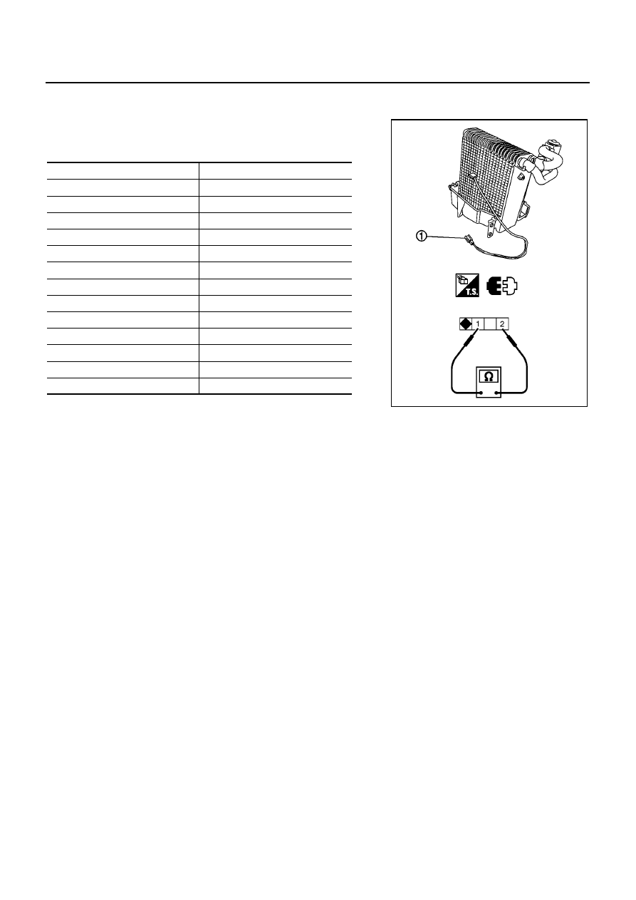
ATC-110
TROUBLE DIAGNOSIS
COMPONENT INSPECTION
Intake Sensor
After disconnecting intake sensor connector (1) M44, measure resis-
tance between terminals 1 and 2 at sensor side, using the table
below.
If NG, replace intake sensor.
Temperature
°
C (
°
F)
Resistance k
Ω
−
15 (5)
12.34
−
10 (14)
9.62
−
5 (23)
7.56
0 (32)
6.00
5 (41)
4.80
10 (50)
3.87
15 (59)
3.15
20 (68)
2.57
25 (77)
2.12
30 (86)
1.76
35 (95)
1.47
40 (104)
1.23
45 (113)
1.04
MJIB0470E
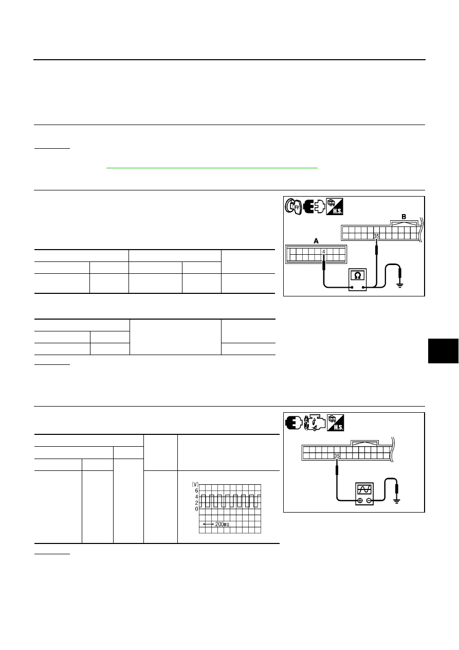
TROUBLE DIAGNOSIS
ATC-111
C
D
E
F
G
H
I
K
L
M
A
B
ATC
Engine Coolant Temperature Circuit
BJS000BT
Symptom: Low engine coolant temperature startup airflow control cannot be cancelled, or the mode cannot be
switched to low engine coolant temperature startup airflow control.
Inspection Procedure
1.
COMBINATION METER FUNCTION INSPECTION
Is engine coolant temperature gauge operating normally?
OK or NG
OK
>> GO TO 2.
NG
>> GO TO
DI-19, "Check Water Temperature Warning/indicator Lamp"
of Combination Meter.
2.
HARNESS INSPECTION
1.
Turn ignition switch OFF.
2.
Disconnect auto amp. connector and combination meter con-
nector.
3.
Check continuity between auto amp. harness connector (A) and
combination meter harness connector (B).
4.
Check continuity between auto amp. harness connector (A) and
ground.
OK or NG
OK
>> GO TO 3.
NG
>> Repair harness and connector.
3.
ENGINE COOLANT TEMPERATURE SIGNAL INSPECTION
After warming up engine, check voltage waveform between combi-
nation meter harness connector and ground.
OK or NG
OK
>> Replace auto amp.
NG
>> Replace combination meter.
A
B
Continuity
Connector
Terminal
Connector
Terminal
Auto amp.: M64
4
Combination
meter: M27
35
Yes
A
Ground
Continuity
Connector
Terminal
Auto amp.: M64
4
No
MJIB0428E
Terminals
Condition
Voltage (approx.)
(+)
(
−
)
Connector
Terminal
Ground
Combination
meter: M27
35
After
warming
up,
approx.
80
°
C.
MJIB0429E
SKIB3651J
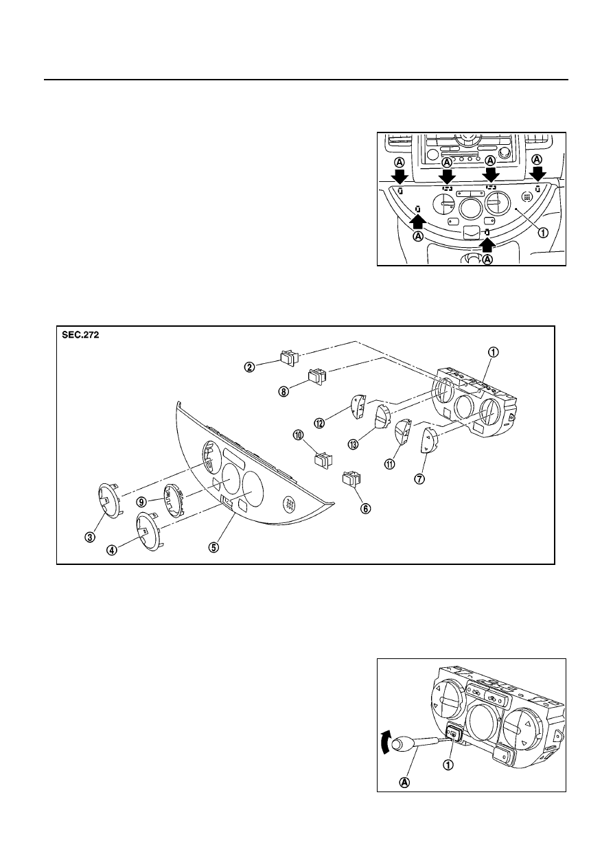
ATC-112
CONTROLLER
CONTROLLER
PFP:28074
Removal and Installation of Controller
BJS000BU
REMOVAL
1.
Remove controller mounting clips (A) using remover tool.
2.
Disconnect controller harness connector and front passenger air
bag OFF indicator harness connector.
3.
Remove controller (1).
INSTALLATION
Installation is basically the reverse order of removal.
Disassembly and Assembly of Controller
BJS000BV
DISASSEMBLY
1.
Remove rear DEF button (1) using screwdriver (A).
ZJIA0790J
1.
Controller assembly
2.
FRE button
3.
MODE ring
4.
TEMP ring
5.
A/C finisher
6.
A/C button
7.
TEMP button
8.
REC button
9.
LCD ring
10. Rear DEF button
11.
AUTO button
12. FAN button
13. MODE button
ZJIA0791J
ZJIA0792J
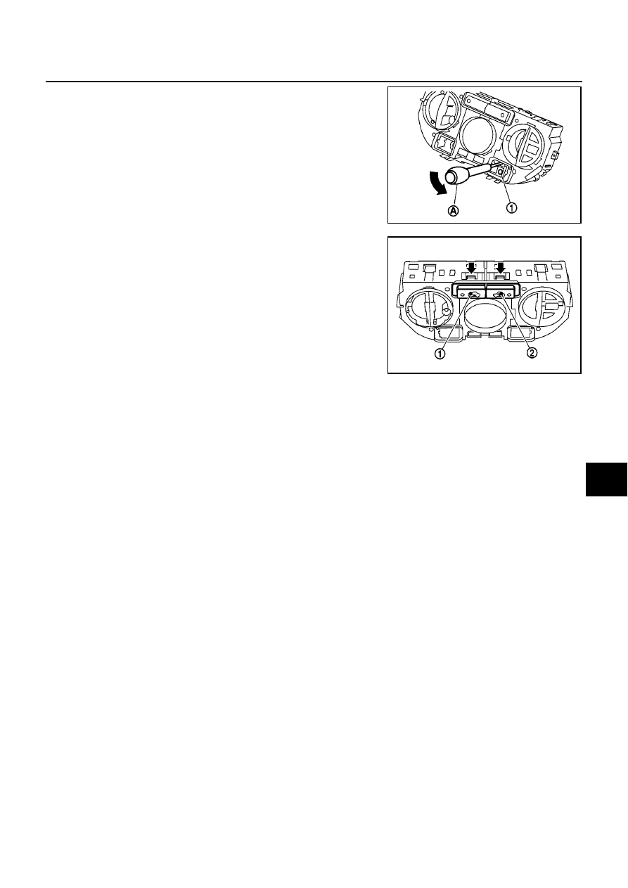
CONTROLLER
ATC-113
C
D
E
F
G
H
I
K
L
M
A
B
ATC
2.
Remove A/C button (1) using screwdriver (A).
3.
Remove FRE button (1) and REC button (2) using screwdriver.
ASSEMBLY
Assembly is basically the reverse order of disassembly.
ZJIA0793J
ZJIA0794J
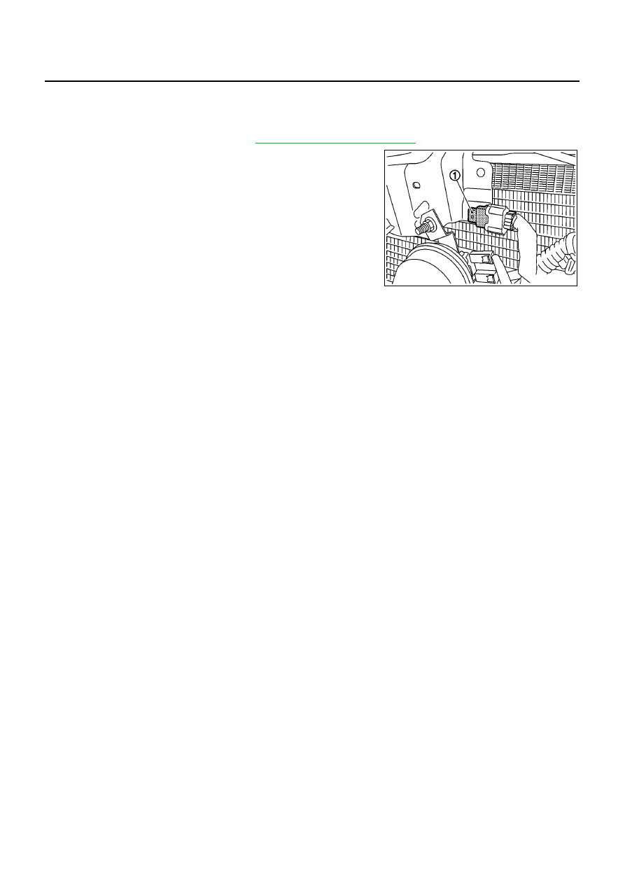
ATC-114
AMBIENT SENSOR
AMBIENT SENSOR
PFP:27722
Removal and Installation
BJS000BY
REMOVAL
1.
Remove front grille (left side). Refer to
EI-10, "Removal and Installation"
.
2.
Disconnect ambient sensor connector, and then remove ambi-
ent sensor (1).
INSTALLATION
Installation is basically the reverse order of removal.
MJIB0467E
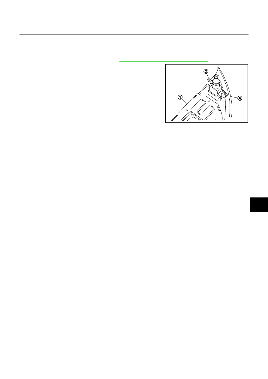
IN-VEHICLE SENSOR
ATC-115
C
D
E
F
G
H
I
K
L
M
A
B
ATC
IN-VEHICLE SENSOR
PFP:27720
Removal and Installation
BJS000BZ
REMOVAL
1.
Remove instrument lower finisher. Refer to
IP-4, "INSTRUMENT PANEL ASSEMBLY"
.
2.
Remove mounting screw (A), and then remove in-vehicle sensor
(1) from instrument lower finisher (2).
INSTALLATION
Installation is basically the reverse order of removal.
MJIB0430E
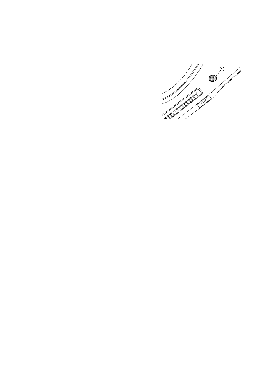
ATC-116
SUNLOAD SENSOR
SUNLOAD SENSOR
PFP:27721
Removal and Installation
BJS000C0
REMOVAL
1.
Remove instrument upper mask. Refer to
IP-4, "INSTRUMENT PANEL ASSEMBLY"
.
2.
Disconnect sunload sensor connector, and then remove sunload
sensor (1).
INSTALLATION
Installation is basically the reverse order of removal.
MJIB0431E
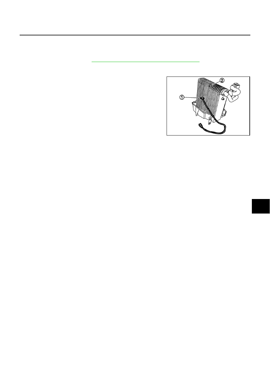
INTAKE SENSOR
ATC-117
C
D
E
F
G
H
I
K
L
M
A
B
ATC
INTAKE SENSOR
PFP:27723
Removal and Installation
BJS000C1
REMOVAL
1.
Remove evaporator. Refer to
ATC-145, "Removal and Installation for Evaporator"
.
CAUTION:
Cap or wrap the joint of the pipe with suitable material such as vinyl tape to avoid the entry of air.
2.
Remove intake sensor (1) from evaporator (2).
INSTALLATION
Installation is basically the reverse order of removal.
CAUTION:
●
Replace O-rings for A/C piping with new ones, and then apply compressor oil to it when installing
it.
●
Mark the mounting position of intake sensor.
●
When recharging refrigerant, check for leaks.
MJIB0459E
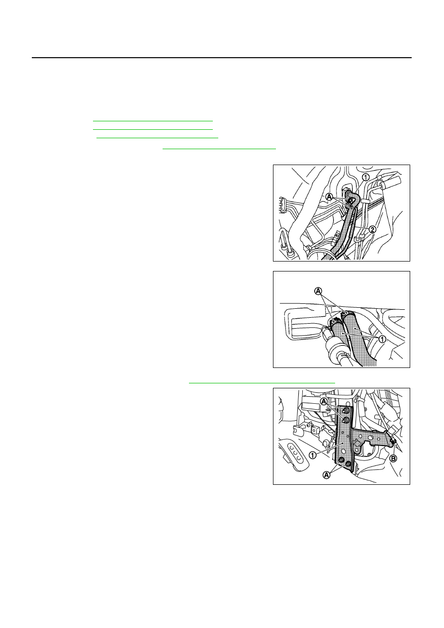
ATC-118
A/C UNIT ASSEMBLY
A/C UNIT ASSEMBLY
PFP:27110
Removal and Installation
BJS000C2
REMOVAL
1.
Use a refrigerant collecting equipment (for HFC-134a) to discharge refrigerant.
2.
Drain coolant from cooling system.
CR: Refer to
CO-28, "Changing Engine coolant"
.
HR: Refer to
CO-28, "Changing Engine coolant"
.
K9K: Refer to
CO-49, "Changing Engine Coolant"
.
3.
Remove cowl top cover. Refer to
EI-12, "Removal and Installation"
.
4.
Remove lower dash insulator.
5.
Remove mounting bolt (A), and then disconnect low-pressure
flexible hose (1) and high-pressure pipe (2) from evaporator.
CAUTION:
Cap or wrap the joint of the pipe with suitable material such
as vinyl tape to avoid the entry of air.
6.
Remove clamps (A), and then disconnect heater hoses (1) from
heater core.
7.
Remove console box assembly. Refer to
IP-4, "INSTRUMENT PANEL ASSEMBLY"
.
8.
Remove mounting nuts (A) and harness clamps (B), and then
remove instrument stay (1).
MJIB0471E
MJIB0472E
MJIB0473E
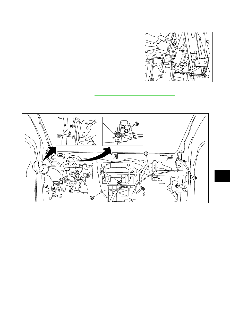
A/C UNIT ASSEMBLY
ATC-119
C
D
E
F
G
H
I
K
L
M
A
B
ATC
9.
Disconnect intake sensor connector (1).
10. Remove instrument panel & pad. Refer to
IP-4, "INSTRUMENT PANEL ASSEMBLY"
.
11. Remove side ventilator ducts. Refer to
ATC-132, "Removal of Side Ventilator Ducts"
.
12. Remove center ventilator ducts. Refer to
ATC-132, "Removal of Center Ventilator Ducts"
.
13. Remove A/C unit assembly mounting bolts (A), steering member mounting bolts (B), steering column
mounting nuts (C) and harness clips.
14. Remove steering member, and then remove A/C unit assembly.
MJIB0474E
MJIB0435E

ATC-120
A/C UNIT ASSEMBLY
INSTALLATION
Installation is basically the reverse order of removal.
CAUTION:
●
Replace O-rings for A/C piping with new ones, and then apply compressor oil to it when installing
it.
●
When recharging refrigerant, check for leaks.
NOTE:
●
When filling radiator with coolant.
CR: Refer to
CO-9, "Changing Engine coolant"
.
HR: Refer to
CO-28, "Changing Engine coolant"
.
K9K: Refer to
CO-49, "Changing Engine Coolant"
.
●
Recharge the refrigerant.
A/C unit assembly mounting bolt
Tightening torque
: 6.9 N·m (0.7 kg-m, 61 in-lb)
Steering member mounting bolt
Tightening torque
: 12 N·m (1.25 kg-m, 9 ft-lb)
Steering column mounting nut
Tightening torque
: 12 N·m (1.25 kg-m, 9 ft-lb)
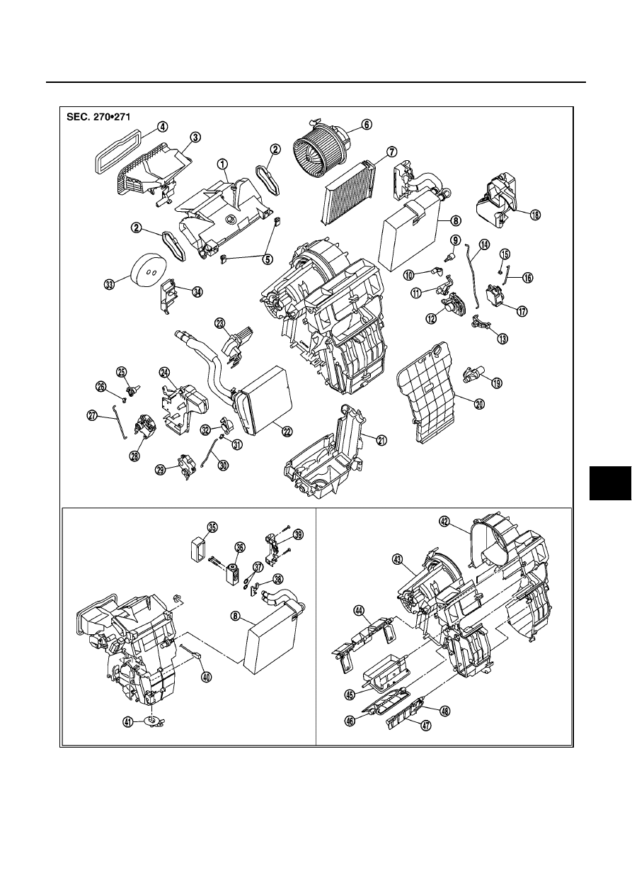
A/C UNIT ASSEMBLY
ATC-121
C
D
E
F
G
H
I
K
L
M
A
B
ATC
Disassembly and Assembly
BJS000C3
1.
Center defroster duct
2.
Seal
3.
Intake case
4.
Insulator
5.
Nut
6.
Blower motor
7.
Air conditioner filter
8.
Evaporator assembly
9.
Ventilator-defroster door lever
10.
Foot door lever
11.
Air mix door link
12.
Main link
13.
Foot door link
14.
Rod
15.
Rod holder
16.
Rod
17.
Mode door motor
18.
Foot duct assembly (RH)
MJIB0480E

ATC-122
A/C UNIT ASSEMBLY
19.
Aspirator
20.
Heater cover
21.
Lower blower case
22.
Heater core assembly
23.
Power transistor
24.
Foot duct assembly (LH)
25.
Intake door lever
26.
Rod holder
27.
Rod
28.
Intake door motor
29.
Air mix door motor
30.
Rod
31.
Rod holder
32.
Air mix door lever
33.
Heater pipe packing
34.
Heater hose cover
35.
Cover
36.
Expansion valve assembly
37.
O-ring
38.
Evaporator valve block
39.
Expansion valve cover
40.
Intake sensor
41.
Drain hose
42.
Blower case (RH)
43.
Blower case (LH)
44.
Ventilator-defroster door
45.
Air mix door 1
46.
Air mix door 2
47.
Foot door
48.
Foot door link
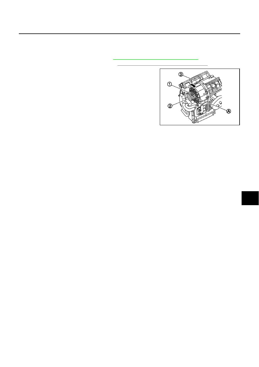
BLOWER MOTOR
ATC-123
C
D
E
F
G
H
I
K
L
M
A
B
ATC
BLOWER MOTOR
PFP:27226
Removal and Installation
BJS000C4
REMOVAL
1.
Remove instrument panel & pad. Refer to
IP-4, "INSTRUMENT PANEL ASSEMBLY"
.
2.
Remove side ventilator duct (right). Refer to
ATC-132, "Removal of Side Ventilator Ducts"
.
3.
Disconnect blower motor connector (1).
4.
Push flange holding hook (A), and then remove blower motor (2)
from A/C unit assembly (3).
CAUTION:
When blower fan and blower motor are assembled, the bal-
ance is adjusted, so do not replace the individual parts.
INSTALLATION
Installation is basically the reverse order of removal.
CAUTION:
Correctly install blower motor flange holding hook in A/C unit assembly.
MJIB0440E
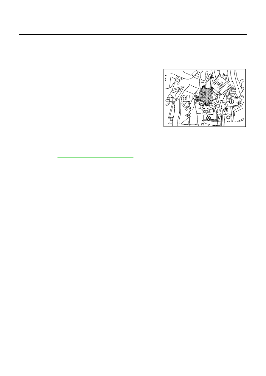
ATC-124
INTAKE DOOR MOTOR
INTAKE DOOR MOTOR
PFP:27730
Removal and Installation
BJS000C5
REMOVAL
1.
Remove instrument lower finisher and instrument lower cover (LH). Refer to
.
2.
Disconnect connector (A).
3.
Remove mounting screws (B), and then remove intake door
motor (1).
INSTALLATION
Installation is basically the reverse order of removal.
CAUTION:
After installing door motor, perform door motor starting position reset by following self-diagnosis
STEP-3. Refer to
ATC-46, "Self-diagnosis Function"
.
MJIB0441E
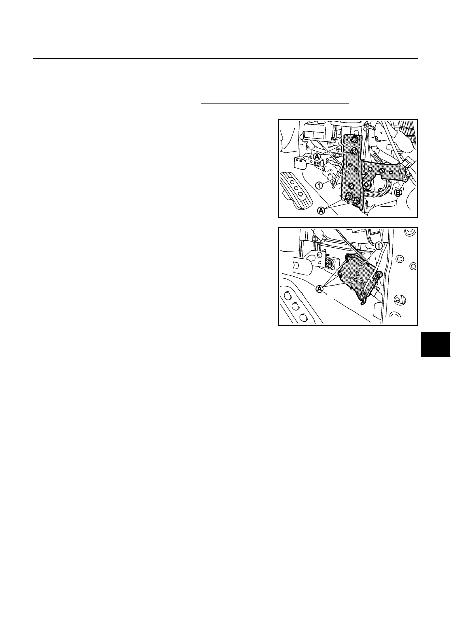
AIR MIX DOOR MOTOR
ATC-125
C
D
E
F
G
H
I
K
L
M
A
B
ATC
AIR MIX DOOR MOTOR
PFP:27732
Removal and Installation
BJS000C6
REMOVAL
1.
Remove instrument lower finisher. Refer to
IP-4, "INSTRUMENT PANEL ASSEMBLY"
.
2.
Remove console box assembly. Refer to
IP-4, "INSTRUMENT PANEL ASSEMBLY"
.
3.
Remove mounting nuts (A) and harness clamps (B), and then
remove instrument stay (1).
4.
Remove mounting screws (A), and then remove air mix door
motor (1).
5.
Disconnect air mix door motor connector.
INSTALLATION
Installation is basically the reverse order of removal.
CAUTION:
After installing door motor, perform door motor starting position reset by following self-diagnosis
STEP-3. Refer to
ATC-46, "Self-diagnosis Function"
.
MJIB0442E
MJIB0443E
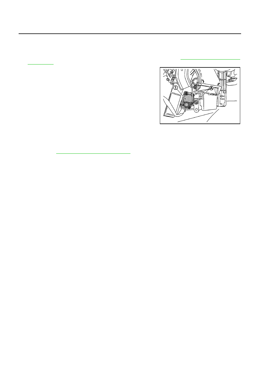
ATC-126
MODE DOOR MOTOR
MODE DOOR MOTOR
PFP:27731
Removal and Installation
BJS000C7
REMOVAL
1.
Remove glove box assembly and instrument lower cover (RH). Refer to
.
2.
Remove mounting screws (A), and then remove mode door
motor (1).
3.
Disconnect mode door motor connector.
INSTALLATION
Installation is basically the reverse order of removal.
CAUTION:
After installing door motor, perform door motor starting position reset by following self-diagnosis
STEP-3. Refer to
ATC-46, "Self-diagnosis Function"
.
MJIB0444E
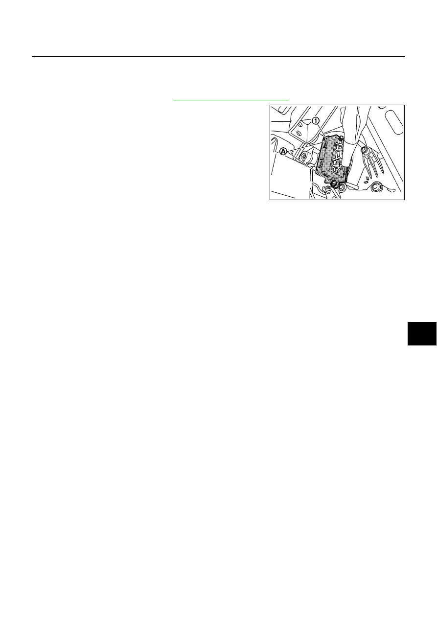
POWER TRANSISTOR
ATC-127
C
D
E
F
G
H
I
K
L
M
A
B
ATC
POWER TRANSISTOR
PFP:27761
Removal and Installation
BJS000C8
REMOVAL
1.
Remove A/C unit assembly. Refer to
.
2.
Remove mounting screws (A), and then remove power transis-
tor (1).
INSTALLATION
Installation is basically the reverse order of removal.
MJIB0445E
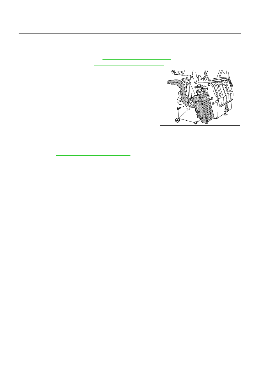
ATC-128
HEATER CORE
HEATER CORE
PFP:27140
Removal and Installation
BJS000C9
REMOVAL
1.
Remove A/C unit assembly. Refer to
.
2.
Remove foot duct (left). Refer to
ATC-132, "Removal of Foot Ducts"
.
3.
Remove mounting screws (A).
4.
Slide heater core (1) to leftward.
INSTALLATION
Installation is basically the reverse order of removal.
CAUTION:
After installing door motor, perform door motor starting position reset by following self-diagnosis
STEP-3. Refer to
ATC-46, "Self-diagnosis Function"
.
MJIB0439E

AIR CONDITIONER FILTER
ATC-129
C
D
E
F
G
H
I
K
L
M
A
B
ATC
AIR CONDITIONER FILTER
PFP:27277
Removal and Installation
BJS000CA
FUNCTION
Air inside passenger compartment is kept clean at either recircula-
tion or fresh mode by installing air conditioner filter into A/C unit
assembly.
REPLACEMENT TIMING
Replace air conditioner filter.
Refer to
MA-55, "CHASSIS AND BODY MAINTENANCE"
.
Caution label is fixed inside glove box.
REPLACEMENT PROCEDURES
1.
Remove glove box assembly. Refer to
IP-4, "INSTRUMENT PANEL ASSEMBLY"
.
2.
Compress air conditioner filter downward while sliding it to the
right side of the vehicle.
3.
Turn the bottom of air conditioner filter upward, and then remove
it.
4.
Replace with new one and reinstall on A/C unit assembly.
5.
Reinstall glove box assembly.
SJIA0651E
MJIB0446E
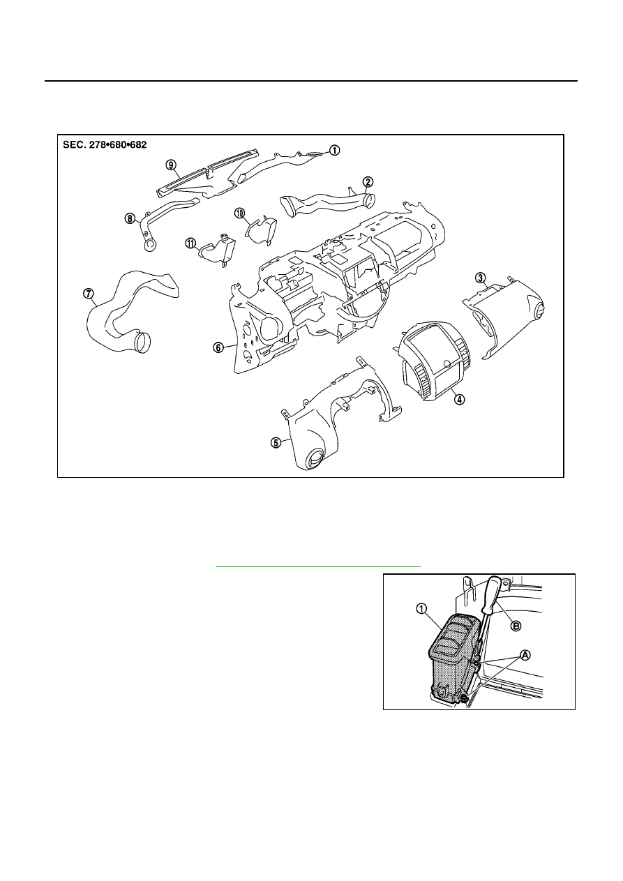
ATC-130
DUCTS AND GRILLES
DUCTS AND GRILLES
PFP:27860
Removal and Installation
BJS000CB
REMOVAL
Removal of Center Ventilator Grilles
1.
Remove cluster lid C. Refer to
IP-4, "INSTRUMENT PANEL ASSEMBLY"
.
2.
Remove center ventilator grilles (1) mounting screws (A) using a
screwdriver (B), and then remove center ventilator grilles (1).
1.
Side defroster duct (right)
2.
Defroster nozzle
3.
Side defroster duct (left)
4.
Side defroster grille (left)
5.
Instrument side panel (left)
6.
Instrument panel & pad
7.
Side ventilator assembly (left)
8.
Cluster lid C
9.
Side ventilator assembly (right)
10. Instrument finisher E
11. Instrument side panel (right)
MJIB0447E
MJIB0448E
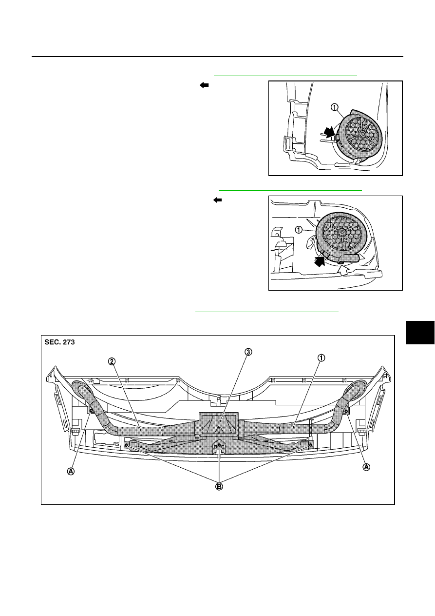
DUCTS AND GRILLES
ATC-131
C
D
E
F
G
H
I
K
L
M
A
B
ATC
Removal of Side Ventilator Grilles
1.
Remove instrument pad assembly (left). Refer to
IP-4, "INSTRUMENT PANEL ASSEMBLY"
.
2.
Side ventilator grille (left) (1) mounting pawl (
) is pushed, and
side ventilator grille (left)(1) is pulled out.
3.
Remove instrument pad assembly (right). Refer to
IP-4, "INSTRUMENT PANEL ASSEMBLY"
.
4.
Side ventilator grille (right) (1) mounting pawl (
) is pushed,
and side ventilator grille (right)(1) is pulled out.
Removal of Defroster Nozzle and Ducts
1.
Remove instrument upper finisher. Refer to
IP-4, "INSTRUMENT PANEL ASSEMBLY"
.
2.
Remove mounting screws (A) and then remove side defroster duct (right) (1) and side defroster duct (left)
(2).
3.
Remove mounting screws (B), and then remove defroster nozzle (3).
MJIB0449E
MJIB0450E
MJIB0451E
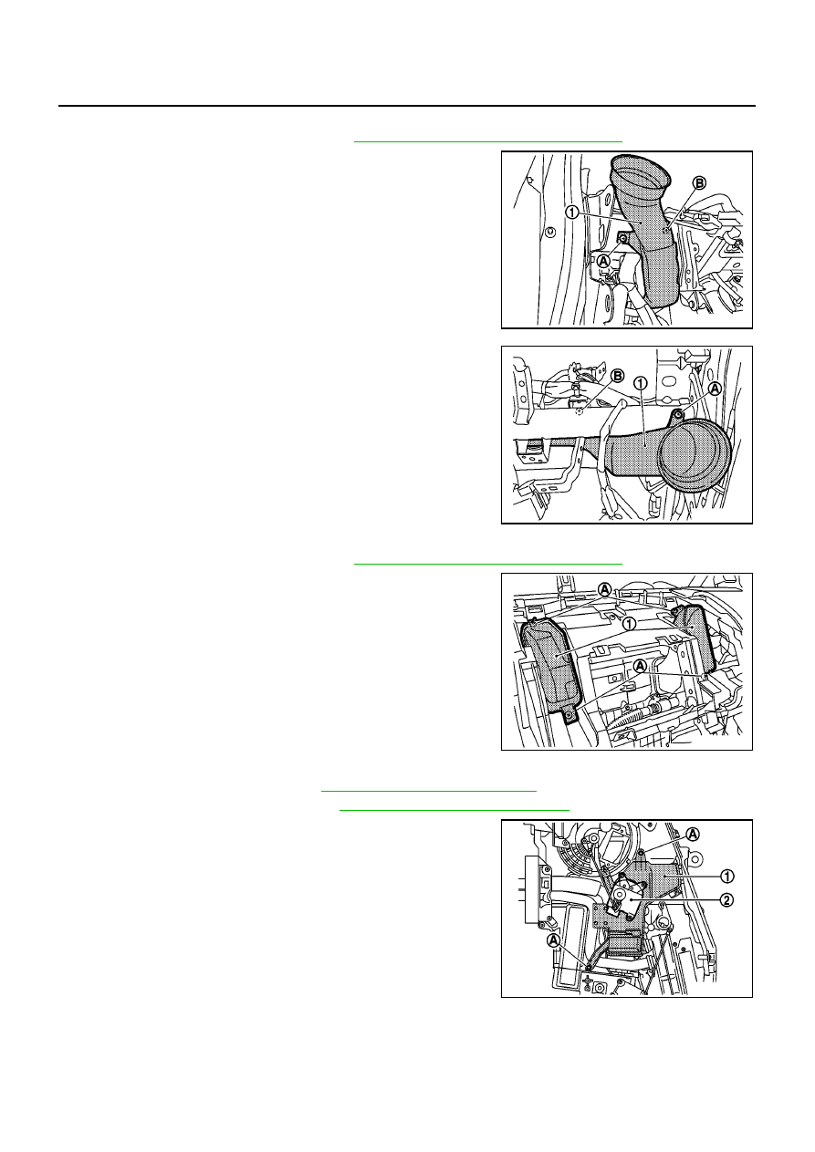
ATC-132
DUCTS AND GRILLES
Removal of Side Ventilator Ducts
1.
Remove instrument panel & pad. Refer to
IP-4, "INSTRUMENT PANEL ASSEMBLY"
.
2.
Remove mounting screws (A) and clip (B), and then remove
side ventilator duct (left) (1).
3.
Remove mounting screw (A) and clip (B), and then remove side
ventilator duct (right) (1).
Removal of Center Ventilator Ducts
1.
Remove instrument panel & pad. Refer to
IP-4, "INSTRUMENT PANEL ASSEMBLY"
.
2.
Remove mounting screws (A), and then remove center ventila-
tor ducts (1).
Removal of Foot Ducts
1.
Remove A/C unit assembly. Refer to
.
2.
Remove intake door motor (2). Refer to
.
3.
Remove mounting screws (A), and then remove foot duct (left)
(1).
MJIB0475E
MJIB0476E
MJIB0477E
MJIB0452E
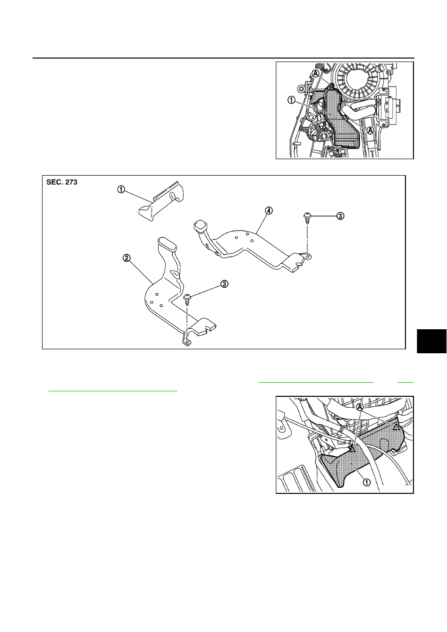
DUCTS AND GRILLES
ATC-133
C
D
E
F
G
H
I
K
L
M
A
B
ATC
4.
Remove mounting screws (A), and then remove foot duct (right)
(1).
Removal of Floor Ducts
1.
Remove front seats and center console assembly. Refer to
SE-8, "Removal and Installation"
and
.
2.
Disengage claws (A), and then remove front floor duct (1).
3.
Peel back floor trim to a point where floor duct is visible.
MJIB0453E
1.
Front floor duct
2.
Rear floor duct (left)
3.
Clip
4.
Rear floor duct (right)
MJIB0454E
MJIB0455E
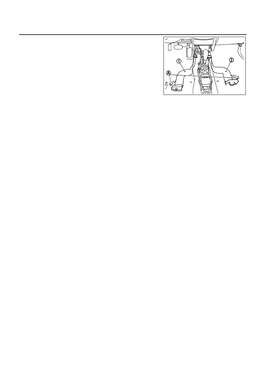
ATC-134
DUCTS AND GRILLES
4.
Remove mounting clips (A), and then remove rear floor duct
(left) (1) and rear floor duct (right) (2).
INSTALLATION
Installation is basically the reverse order of removal.
MJIB0456E
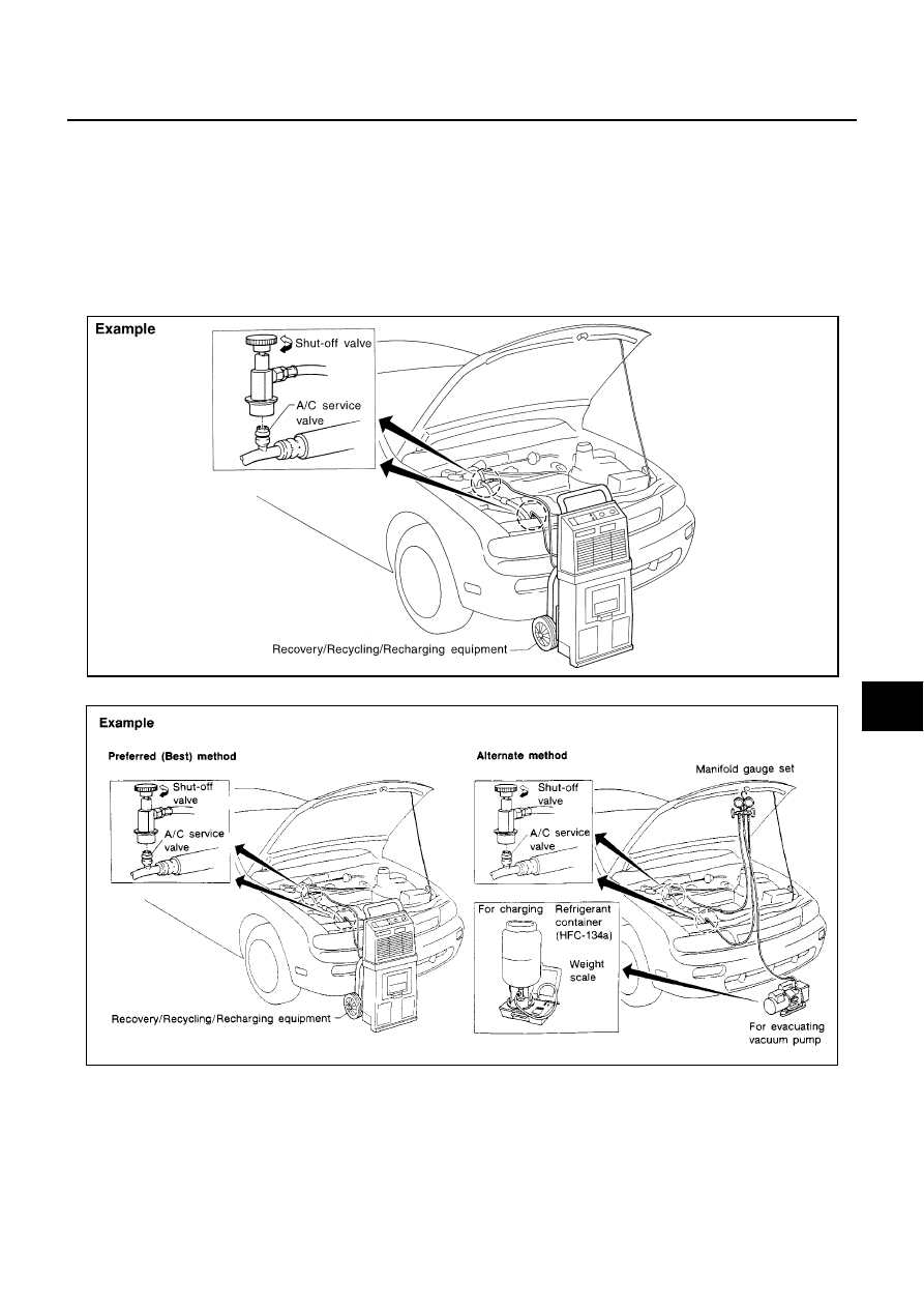
REFRIGERANT LINES
ATC-135
C
D
E
F
G
H
I
K
L
M
A
B
ATC
REFRIGERANT LINES
PFP:92600
HFC-134a (R-134a) Service Procedure
BJS000CC
SETTING OF SERVICE TOOLS AND EQUIPMENT
Discharging Refrigerant
WARNING:
Avoid breathing A/C refrigerant and lubricant vapor or mist. Exposure may irritate eyes, nose and
throat. Use only approved recovery/recycling equipment to discharge HFC-134a (R-134a) refrigerant. If
accidental system discharge occurs, ventilate work area before resuming service. Additional health
and safety information may be obtained from refrigerant and lubricant manufacturers.
Evacuating System and Charging Refrigerant
SHA539DE
SHA540DC
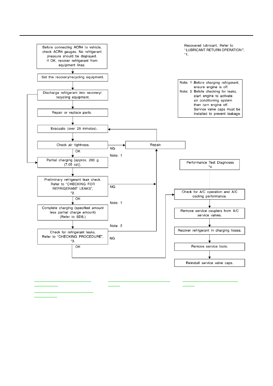
ATC-136
REFRIGERANT LINES
*1
ATC-17, "LUBRICANT RETURN
OPERATION"
*2
ATC-147, "Checking for Refrigerant
Leaks"
*3
ATC-149, "CHECKING PROCE-
DURE"
*4
ATC-88, "PERFORMANCE TEST
DIAGNOSIS"
RJIA2143E
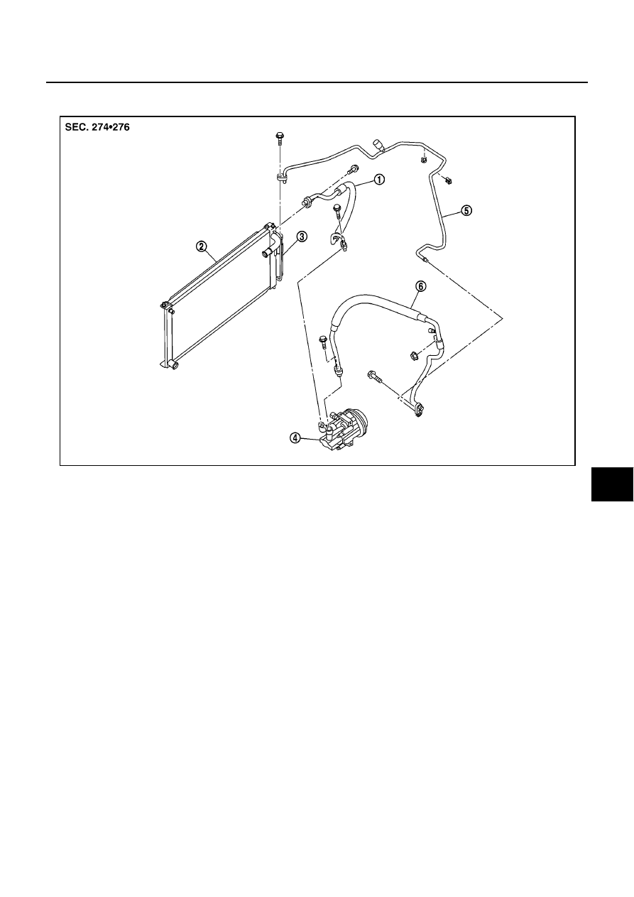
REFRIGERANT LINES
ATC-137
C
D
E
F
G
H
I
K
L
M
A
B
ATC
Components
BJS000CD
CR ENGINE MODELS
1.
High-pressure flexible hose
2.
Radiator (Condenser)
3.
Liquid tank
4.
Compressor
5.
High-pressure pipe
6.
Low-pressure flexible hose
MJIB0436E
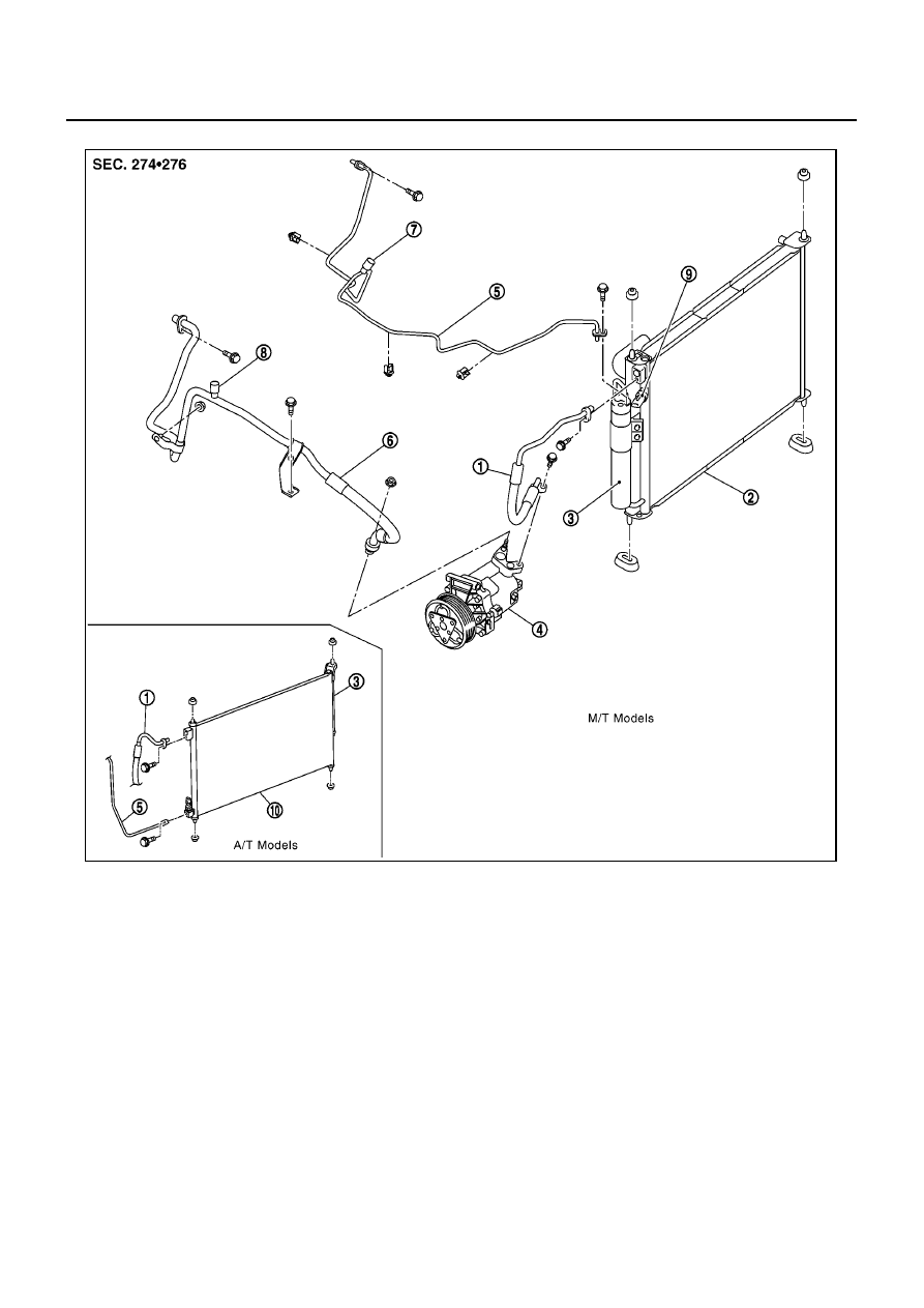
ATC-138
REFRIGERANT LINES
HR ENGINE MODELS
1.
High-pressure flexible hose
2.
Radiator (Condenser)
3.
Liquid tank
4.
Compressor
5.
High-pressure pipe
6.
Low-pressure flexible hose
7.
Service valve (High pressure)
8.
Service valve (Low pressure)
9.
Refrigerant pressure sensor
10. Condenser
MJIB0437E
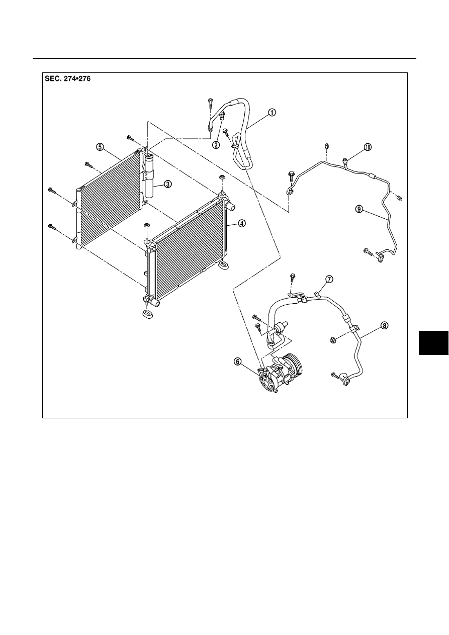
REFRIGERANT LINES
ATC-139
C
D
E
F
G
H
I
K
L
M
A
B
ATC
K9K ENGINE MODELS
1.
High-pressure flexible hose
2.
Refrigerant pressure sensor
3.
Liquid tank
4.
Radiator (Condenser)
5.
Condenser
6.
Compressor
7.
Service valve (Low pressure)
8.
Low-pressure flexible hose
9.
High-pressure pipe
10. Service valve (High pressure)
MJIB0438E
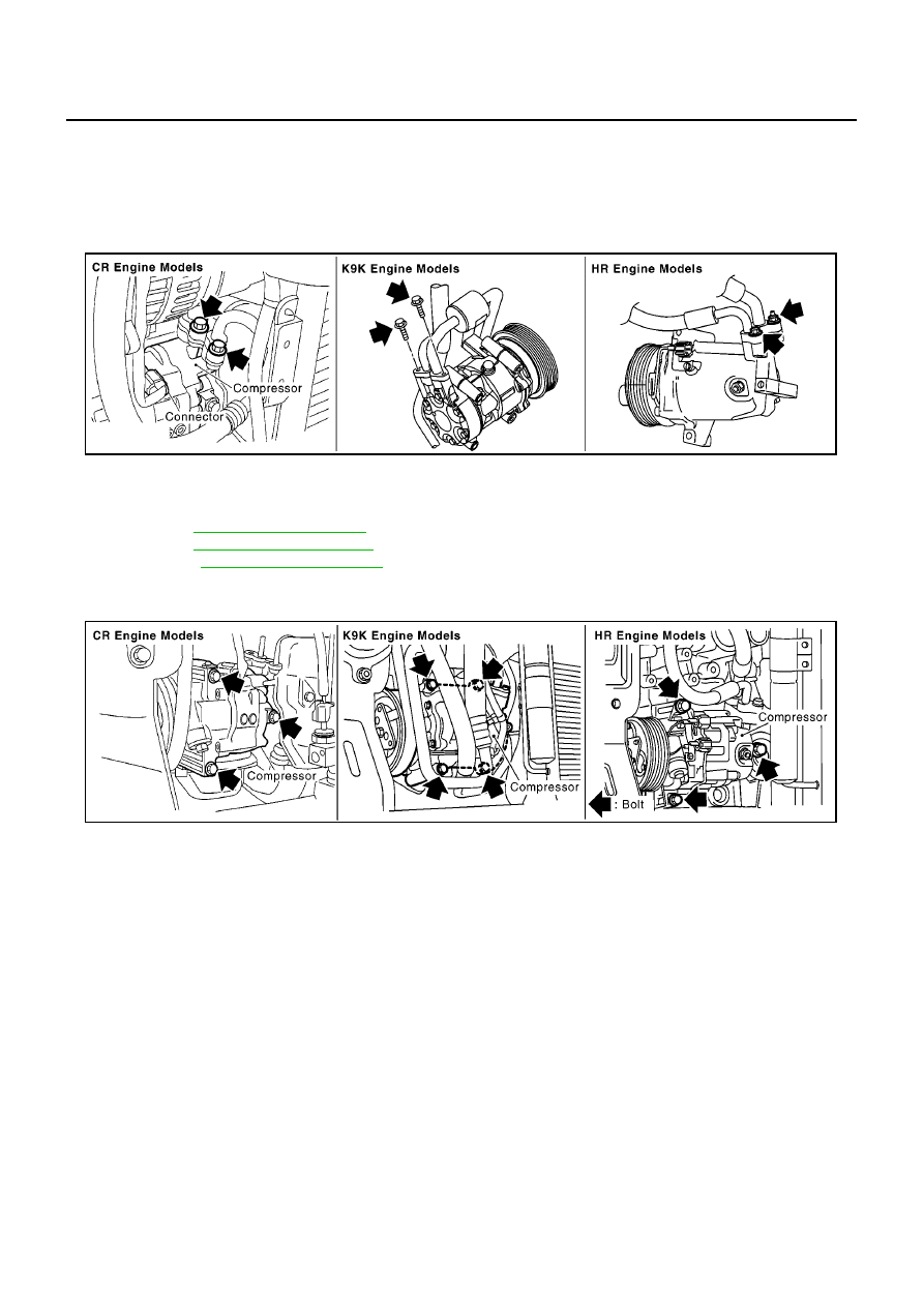
ATC-140
REFRIGERANT LINES
Removal and Installation of Compressor
BJS000CE
REMOVAL
1.
Use a refrigerant collecting equipment (for HFC-134a) to discharge the refrigerant.
2.
Remove engine undercover, using power tools.
3.
Remove low-pressure flexible hose mounting nut and high-pressure flexible hose mounting bolt from
compressor.
CAUTION:
Cap or wrap the joint of the pipe with suitable material such as vinyl tape to avoid the entry of air.
4.
Remove A/C compressor belt.
CR: Refer to
.
HR: Refer to
.
K9K: Refer to
.
5.
Disconnect compressor connector.
6.
Remove mounting bolts from compressor, using power tools.
7.
Remove compressor downward of the vehicle.
INSTALLATION
Installation is basically the reverse order of removal.
CAUTION:
●
Replace O-rings of low-pressure flexible hose and high-pressure flexible hose with a new ones,
and then apply compressor oil to it when installing it.
●
When recharging refrigerant, check for leaks.
MJIB0273E
MJIB0134E
Compressor mounting bolt
Tightening torque
: 20.0 N·m (2.05 kg-m, 14.8 ft-lb)
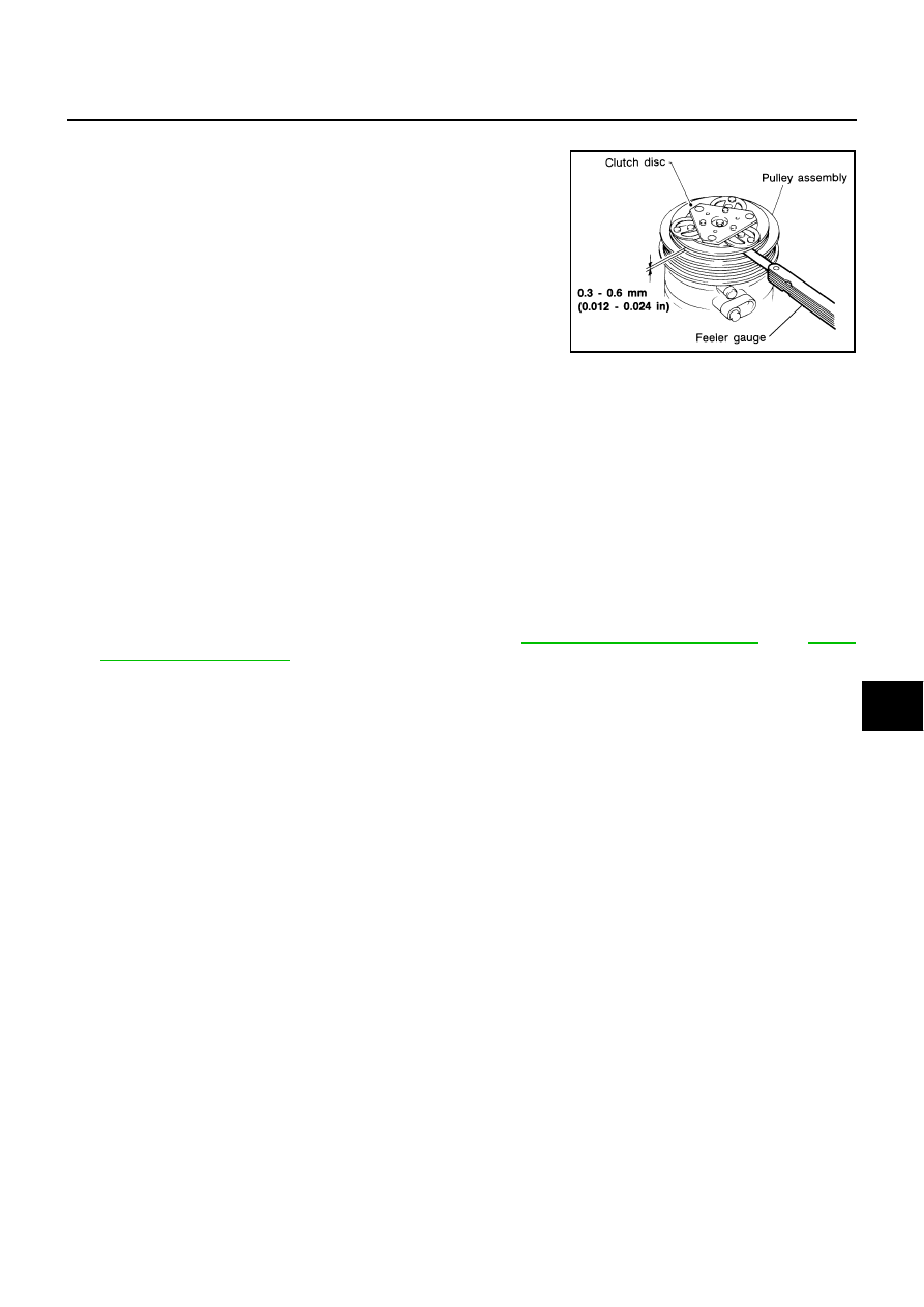
REFRIGERANT LINES
ATC-141
C
D
E
F
G
H
I
K
L
M
A
B
ATC
CHECK DISC TO PULLEY CLEARANCE
Check clearance around entire periphery of clutch disc.
If specified clearance is not obtained, replace compressor.
Removal and Installation for Pipe and Hose
BJS000I9
REMOVAL
1.
Use recovery/recycling recharging equipment [for HFC-134a (R-134a)] to discharge refrigerant.
2.
Remove the low-pressure flexible hose bracket mounting bolt and nut.
3.
Remove the high-pressure pipe and low-pressure flexible hose mounting bolts (air conditioner unit side).
CAUTION:
Seal the connecting points of the pipe and hose with caps and vinyl tape, etc. to prevent them from
being exposed to the atmosphere.
4.
Remove the low-pressure flexible hose mounting bolt or nut (compressor side) and then remove the low-
pressure flexible hose.
CAUTION:
Seal the connecting points of the hose with caps and vinyl tape, etc. to prevent them from being
exposed to the atmosphere.
5.
Remove the front bumper and air guide (RH). Refer to
EI-4, "Removal and Installation"
and
.
6.
Remove the high-pressure pipe mounting bolt (liquid tank side) and then remove the high-pressure pipe.
CAUTION:
Seal the connecting points of the pipe with caps and vinyl tape, etc. to prevent them from being
exposed to the atmosphere.
7.
Remove the high-pressure flexible hose mounting bolts and then remove the high-pressure flexible hose.
CAUTION:
Seal the connecting points of the hoses with caps and vinyl tape, etc. to prevent them from being
exposed to the atmosphere.
INSTALLATION
CAUTION:
●
Replace the O-rings on the high-pressure pipe, low-pressure flexible hose, and high-pressure flex-
ible hose with new ones, and apply compressor lubricant to O-rings before installing.
●
When charging refrigerant, check for refrigerant leaks.
Disc to pulley
clearance
: 0.3 - 0.6 mm (0.012 - 0.024 in)
RHA087E
High-pressure pipe mounting bolt
Tightening torque
: 4.4 N·m (0.45 kg-m, 39.0 in-lb)
Low-pressure flexible hose and high-pressure pipe mounting bolts (evaporator side)
Tightening torque
: 4.4 N·m (0.45 kg-m, 39.0 in-lb)
Low-pressure flexible hose mounting bolt (compressor side)
Tightening torque
: 13.7 N·m (1.4 kg-m, 10.1 ft-lb)
Low-pressure flexible hose bracket mounting bolt/nut
Tightening torque
: 4.2 N·m (0.43 kg-m, 37.2 in-lb)
High-pressure flexible hose mounting bolt
Tightening torque
: 13.7 N·m (1.4 kg-m, 10.1 ft-lb)
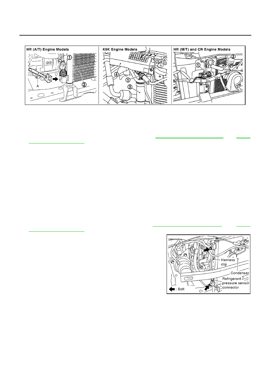
ATC-142
REFRIGERANT LINES
Removal and Installation for Refrigerant Pressure Sensor
BJS000IA
REMOVAL AND INSTALLATION
1.
Use refrigerant collecting equipment (for HFC134a) to discharge refrigerant.
2.
Remove the front bumper and air guide (RH) (4). Refer to
EI-4, "Removal and Installation"
and
.
3.
Use a adjustable wrench A or other tool to hold the refrigerant pressure sensor mounting block, and then
remove the refrigerant pressure sensor from the condenser (CR and HR engine models) or the high-pres-
sure flexible hose (K9K engine models).
CAUTION:
●
Be careful when working so as not to damage the condenser core.
●
When installing refrigerant pressure sensor, apply compressor lubricant to the O-rings.
Removal and Installation for Condenser (Models without Integrated Condenser)
BJS000IB
REMOVAL
1.
Use refrigerant collecting equipment (for HFC134a) to discharge refrigerant.
2.
Remove the front bumper and air guide (RH). Refer to
EI-4, "Removal and Installation"
and
.
3.
Disconnect the high-pressure flexible hose and high-pressure
pipe from the condenser.
CAUTION:
Seal the connecting points of the pipes with caps and vinyl
tape, etc. to prevent them from being exposed to the atmo-
sphere.
4.
Disconnect the refrigerant pressure sensor connector, and then
remove the harness clip (CR engine models).
1.
Refrigerant pressure sensor
2.
Condenser
3.
Liquid tank
4.
Air guide
MJIB0457E
Refrigerant pressure sensor
Tightening torque
: 10.8 N·m (1.1 kg-m, 8.0 ft-lb)
MJIA0059E
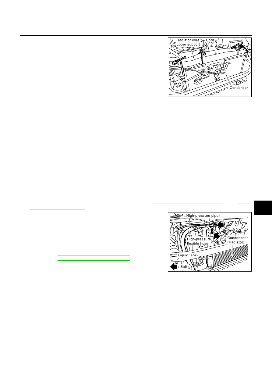
REFRIGERANT LINES
ATC-143
C
D
E
F
G
H
I
K
L
M
A
B
ATC
5.
Use cord, etc., to hold the condenser and radiator to each radia-
tor core support upper.
NOTE:
To prevent the condenser and radiator from being dropped when
the radiator core lower support is removed.
6.
Remove the mounting bolts, and then remove the radiator core
lower support.
7.
Remove the condenser from underneath the vehicle.
CAUTION:
Do not damage the condenser core.
INSTALLATION
CAUTION:
●
Replace O-rings on the high-pressure pipe and high-pressure flexible hose with new ones. Apply
compressor lubricant to O-rings when installing them.
●
When charging refrigerant, check for refrigerant leaks.
Removal and Installation for Condenser (Models with Integrated Condenser)
BJS000IC
REMOVAL
1.
Use refrigerant collecting equipment (for HFC134a) to discharge refrigerant.
2.
Remove the front bumper and air guide (RH). Refer to
EI-4, "Removal and Installation"
and
.
3.
Disconnect the high-pressure flexible hose from the condenser.
Disconnect the high-pressure pipe from the liquid tank.
CAUTION:
Seal the connecting points of the pipes with caps and vinyl
tape, etc. to prevent them from being exposed to the atmo-
sphere.
4.
Remove the radiator assembly.
CR: Refer to
CO-12, "Removal and Installation"
.
HR: Refer to
CO-31, "Removal and Installation"
.
CAUTION:
Do not damage the radiator and condenser core.
INSTALLATION
CAUTION:
●
Replace O-rings on the high-pressure pipe and high-pressure flexible hose with new ones. Apply
compressor lubricant to O-rings when installing them.
●
When charging refrigerant, check for refrigerant leaks.
MJIA0060E
High-pressure flexible hose bolt
Tightening torque
: 13.7 N·m (1.4 kg-m, 10.1 ft-lb)
High-pressure pipe mounting bolt
Tightening torque
: 4.4 N·m (0.45 kg-m, 39.0 in-lb)
Radiator core lower support mounting bolts.
Tightening torque
: 51.1 N·m (5.3 kg-m, 37.7 ft-lb)
MJIA0214E
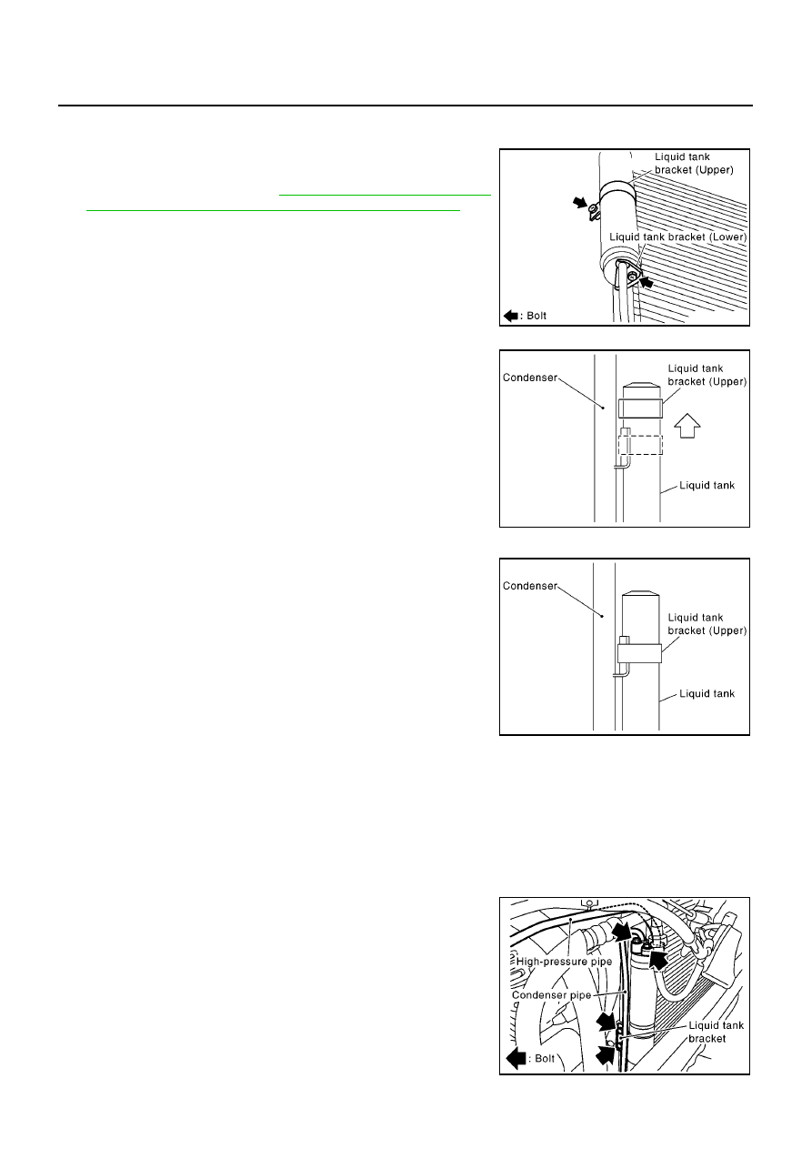
ATC-144
REFRIGERANT LINES
Removal and Installation for Liquid Tank (HR Engine with A/T Models)
BJS000ID
REMOVAL
1.
Use refrigerant collecting equipment (for HFC134a) to discharge
refrigerant.
2.
Remove condenser. Refer to
ATC-142, "Removal and Installa-
tion for Condenser (Models without Integrated Condenser)"
.
3.
Clean around the liquid tank to remove foreign material and cor-
rosion.
4.
Remove the liquid tank bracket (upper/lower) mounting bolts.
5.
Lift up the liquid tank bracket, and remove it from the condenser
protruding area.
6.
Lift up the liquid tank and remove it.
CAUTION:
Seal the connecting points of the pipes with caps and vinyl
tape, etc. to prevent them from being exposed to the atmo-
sphere.
INSTALLATION
Install the liquid tank, and then install liquid tank bracket to the con-
denser.
CAUTION:
●
Make sure the liquid tank bracket is correctly inserted into
the condenser's protruding area (the liquid tank bracket
does not move below the center of the liquid tank).
●
Replace the condenser pipe O-rings with new ones. Apply a
coat of compressor lubricant to the O-rings prior to installa-
tion.
Removal and Installation for Liquid Tank (Except HR Engine with A/T Models)
BJS000IE
REMOVAL
1.
Use refrigerant collecting equipment (for HFC134a) to discharge
refrigerant.
2.
Clean around the liquid tank to remove foreign material and cor-
rosion.
3.
Remove the high-pressure pipe from the liquid tank.
4.
Remove the condenser pipe mounting bolt from the liquid tank,
and remove pipe from the condenser protruding area.
5.
Remove the liquid tank bracket bolts and then remove the liquid
tank.
MJIA0061E
MJIA0062E
MJIA0063E
Liquid tank bracket (upper) mounting bolt
Tightening torque
: 3.38 N·m (0.35 kg-m, 30.0 in-lb)
Liquid tank bracket (lower) mounting bolt
Tightening torque
: 5.74 N·m (0.58 kg-m, 50.8 in-lb)
MJIA0215E
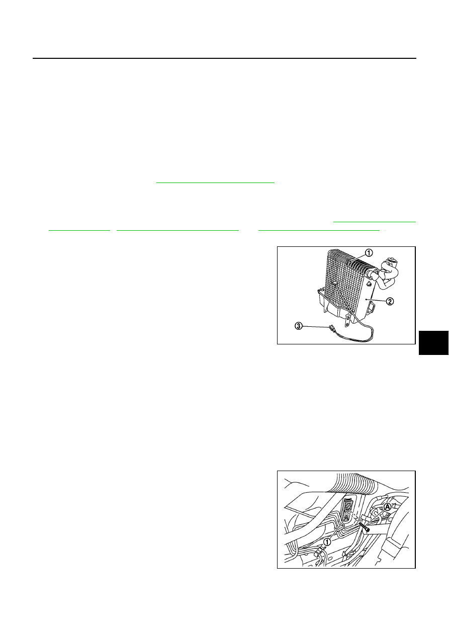
REFRIGERANT LINES
ATC-145
C
D
E
F
G
H
I
K
L
M
A
B
ATC
CAUTION:
Seal the connecting points of the pipes with caps and vinyl tape, etc. to prevent them from being
exposed to the atmosphere.
INSTALLATION
Install the liquid tank, and then install liquid tank bracket to the condenser.
CAUTION:
Replace the condenser pipe O-rings with new ones. Apply a coat of compressor lubricant to the O-
rings prior to installation.
Removal and Installation for Evaporator
BJS000IF
REMOVAL
1.
Use refrigerant collecting equipment (for HFC134a) to discharge refrigerant.
2.
Remove the A/C unit. Refer to
.
CAUTION:
Seal the connecting points of the pipes with caps and vinyl tape, etc. to prevent them from being
exposed to the atmosphere.
3.
Remove the air conditioner filter, mode door motor, and foot duct (RH). Refer to
,
and
ATC-132, "Removal of Foot Ducts"
.
4.
Remove the lower blower case and expansion valve cover.
5.
Slide the evaporator (1) and lower blower case (2) downward,
and remove the intake sensor (3).
6.
Remove the evaporator from the lower blower case.
INSTALLATION
CAUTION:
●
Replace low-pressure flexible hose and high-pressure pipe O-rings with new ones. Apply a coat of
compressor lubricant prior to installation.
●
When installing a new evaporator, install the thermistor of intake air temperature in the same posi-
tion as the removed intake sensor.
●
When removing and installing the intake sensor, do not rotate the thermistor insertion part.
Removal and Installation for Expansion Valve
BJS000IG
REMOVAL
1.
Use refrigerant collecting equipment (for HFC134a) to discharge
refrigerant.
2.
Disconnect the low-pressure flexible hose and high-pressure
pipe from the evaporator.
CAUTION:
Seal the connecting points of the pipes with caps and vinyl
tape, etc. to prevent them from being exposed to the atmo-
sphere.
3.
Remove the two bolts from the expansion valve, and then
remove the expansion valve.
MJIB0462E
Mounting bolts for the low-pressure flexible hoses and high-pressure pipes.
Tightening torque
: 4.4 N·m (0.45 kg-m, 39.0 in-lb)
MJIB0460E

ATC-146
REFRIGERANT LINES
INSTALLATION
CAUTION:
Replace the removed O-rings with new ones. Apply a coat of compressor lubricant to the O-rings prior
to installation.
Expansion valve mounting bolts
Tightening torque
: 4.0 N·m (0.41 kg-m, 35.4 in-lb)
Mounting bolts for the low-pressure flexible hoses and high-pressure pipes.
Tightening torque
: 4.4 N·m (0.45 kg-m, 39.0 in-lb)

REFRIGERANT LINES
ATC-147
C
D
E
F
G
H
I
K
L
M
A
B
ATC
Checking for Refrigerant Leaks
BJS000CN
Perform a visual inspection of all refrigeration parts, fittings, hoses and components for signs of A/C lubricant
leakage, damage and corrosion. A/C lubricant leakage may indicate an area of refrigerant leakage. Allow
extra inspection time in these areas when using either an electronic refrigerant leak detector or fluorescent
dye leak detector.
If dye is observed, confirm the leak with an electronic refrigerant leak detector. It is possible a prior leak was
repaired and not properly cleaned.
When searching for leaks, do not stop when one leak is found but continue to check for additional leaks at all
system components and connections.
When searching for refrigerant leaks using an electronic leak detector, move the probe along the suspected
leak area at 1 to 2 inches per second and no further than 1/4 inch from the component.
CAUTION:
Moving the electronic leak detector probe slower and closer to the suspected leak area will improve
the chances of finding a leak.
Checking System for Leaks Using the Fluorescent Leak Detector
BJS000CO
1.
Check A/C system for leaks using the UV lamp and safety goggles [SST: J-42220] in a low sunlight area
(area without windows preferable). Illuminate all components, fittings and lines. The dye will appear as a
bright green/yellow area at the point of leakage. Fluorescent dye observed at the evaporator drain open-
ing indicates an evaporator core assembly (tubes, core or expansion valve) leak.
2.
If the suspected area is difficult to see, use an adjustable mirror or wipe the area with a clean shop rag or
cloth, with the UV lamp for dye residue.
3.
After the leak is repaired, remove any residual dye using dye cleaner [SST: J-43872] to prevent future mis-
diagnosis.
4.
Perform a system performance check and verify the leak repair with an approved electronic refrigerant
leak detector.
NOTE:
Other gases in the work area or substances on the A/C components, for example, anti-freeze, windshield
washer fluid, solvents and lubricants, may falsely trigger the leak detector. Make sure the surfaces to be
checked are clean.
Clean with a dry cloth or blow off with shop air.
Do not allow the sensor tip of the detector to contact with any substance. This can also cause false readings
and may damage the detector.
Dye Injection
BJS000CP
(This procedure is only necessary when recharging the system or when the compressor has seized and was
replaced.)
1.
Check A/C system static (at rest) pressure. Pressure must be at least 345 kPa (3.45 bar, 3.52 kg/cm
2
, 50
psi).
2.
Pour one bottle (1/4 ounce / 7.4 cc) of the A/C refrigerant dye into the injector tool [SST: J-41459].
3.
Connect the injector tool to the A/C low-pressure side service fitting.
4.
Start engine and switch A/C ON.
5.
When the A/C operating (compressor running), inject one bottle (1/4 ounce / 7.4 cc) of fluorescent dye
through the low-pressure service valve using dye injector tool J-41459 (refer to the manufacture’s operat-
ing instructions).
6.
With the engine still running, disconnect the injector tool from the service fitting.
CAUTION:
Be careful the A/C system or replacing a component, pour the dye directly into the open system
connection and proceed with the service procedures.
7.
Operate the A/C system for a minimum of 20 minutes to mix the dye with the system oil. Depending on the
leak size, operating conditions and location of the leak, it may take from minutes to days for the dye to
penetrate a leak and become visible.
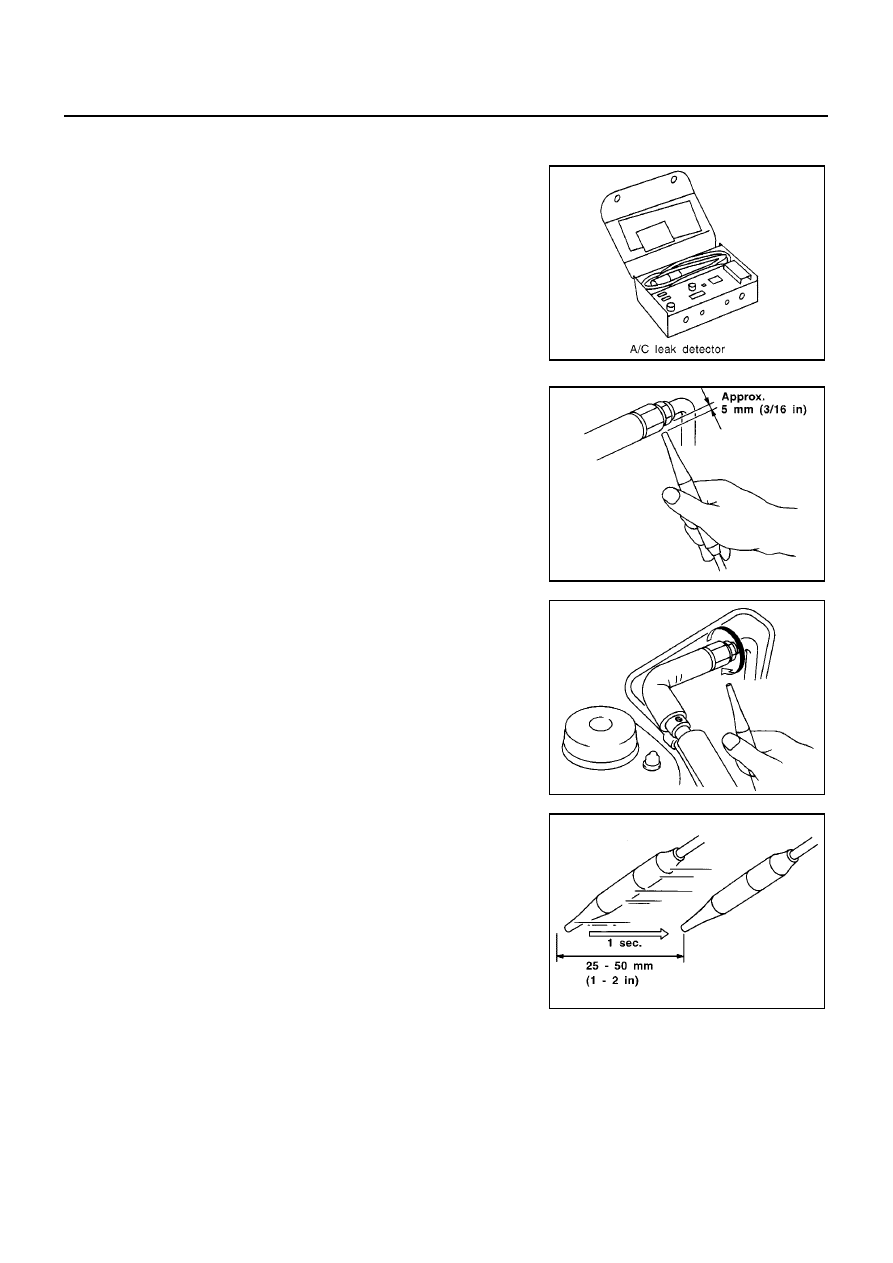
ATC-148
REFRIGERANT LINES
Electronic Refrigerant Leak Detector
BJS000CQ
PRECAUTIONS FOR HANDLING LEAK DETECTOR
When performing a refrigerant leak check, use an A/C electrical leak
detector (SST) or equivalent. Ensure that the instrument is calibrated
and set properly per the operating instructions.
The leak detector is a delicate device. In order to use the leak detec-
tor properly, read the operating instructions and perform any speci-
fied maintenance.
1.
Position probe approximately 5 mm (3/16 in) away from point to
be checked.
2.
When testing, circle each fitting completely with probe.
3.
Move probe along component approximately 25 to 50 mm (1 to
2 in)/sec.
SHA705EB
SHA707EA
SHA706E
SHA708EA

REFRIGERANT LINES
ATC-149
C
D
E
F
G
H
I
K
L
M
A
B
ATC
CHECKING PROCEDURE
To prevent inaccurate or false readings, make sure there is no refrigerant vapor, shop chemicals, or cigarette
smoke in the vicinity of the vehicle. Perform the leak test in calm area (low air/wind movement) so that the
leaking refrigerant is not dispersed.
1.
Turn engine OFF.
2.
Connect a suitable A/C manifold gauge set to the A/C service ports.
3.
Check if the A/C refrigerant pressure is at least 345 kPa (3.45 bar, 3.52 kg/cm
2
, 50 psi) above 16
°
C. If
less than specification, recover/evacuate and recharge the system with the specified amount of refriger-
ant.
NOTE:
At temperatures below 16
°
C, leaks may not be detected since the system may not reach 345 kPa (3.45
bar, 3.52 kg/cm
2
, 50 psi).
4.
Perform the leak test from the high-pressure side (compressor discharge a to evaporator inlet f) to the
low-pressure side (evaporator drain hose g to shaft seal k). Refer to
. Perform a
leak check for the following areas carefully. Clean the component to be checked and move the leak
detected probe completely around the connection/component.
Compressor
Check the fitting of high- and low-pressure flexible hoses, relief valve and shaft seal.
Condenser
Check the fitting of high-pressure flexible hose and pipe, refrigerant pressure sensor.
Liquid tank
Check the refrigerant connection.
Service valves
Check all around the service valves. Ensure service valve caps are secured on the service valves (to pre-
vent leaks).
NOTE:
After removing A/C manifold gauge set from service valves, wipe any residue from valves to prevent any
false readings by leak detector.
Cooling unit (Evaporator)
With engine OFF, turn blower fan on “High” for at least 15 seconds to dissipate any refrigerant trace in the
cooling unit. Wait a minimum of 10 minutes accumulation time (refer to the manufacturer’s recommended
procedure for actual wait time) before inserting the leak detector probe into the drain hose.
Keep the probe inserted for at least 10 seconds. Use caution not to contaminate the probe tip with water
or dirt that may be in the drain hose.
5.
If a leak detector detects a leak, verify at least once by blowing compressed air into area of suspected
leak, then repeat check as outlined above.
6.
Do not stop when one leak is found. Continue to check for additional leaks at all system components.
If no leaks are found, perform steps 7-10.
7.
Start engine.
8.
Set the heater A/C control as follows;
a.
A/C switch: ON
b.
MODE door position: VENT (Ventilation)
c.
Intake door position: Recirculation
d.
Temperature control dial: Max. cold
e.
Fan speed: High
9.
Run engine at 1,500 rpm for at least 2 minutes.
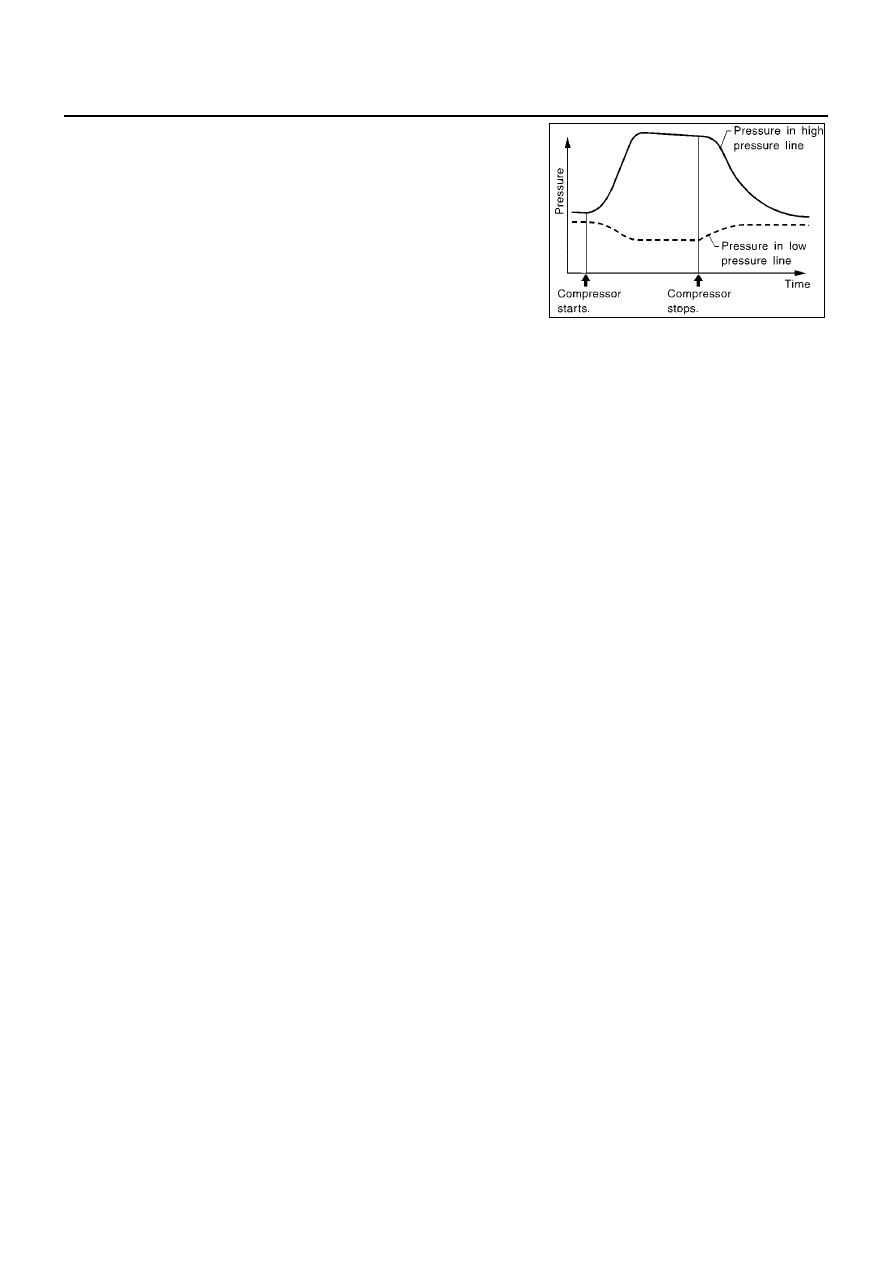
ATC-150
REFRIGERANT LINES
10. Turn engine off and perform leak check again following steps 4
through 6 above.
Refrigerant leaks should be checked immediately after stopping
the engine. Begin with the leak detector at the compressor. The
pressure on the high-pressure side will gradually drop after
refrigerant circulation stops and pressure on the low-pressure
side will gradually rise, as shown in the graph. Some leaks are
more easily detected when pressure is high.
11. Before connecting ACR4 to vehicle, check ACR4 gauges. No
refrigerant pressure should be displayed. If pressure is dis-
played, recover refrigerant from equipment lines.
12. Discharge A/C system using approved refrigerant recovery
equipment. Repair the leaking fitting or component if necessary.
13. Evacuate and recharge A/C system and perform the leak test to confirm no refrigerant leaks.
14. Perform A/C performance test to ensure system works properly.
SHA839E

SERVICE DATA AND SPECIFICATIONS (SDS)
ATC-151
C
D
E
F
G
H
I
K
L
M
A
B
ATC
SERVICE DATA AND SPECIFICATIONS (SDS)
PFP:00030
COMPRESSOR
BJS000IH
LUBRICANT
BJS000J9
REFRIGERANT
BJS000JA
ENGINE IDLING SPEED
BJS000IK
Refer to
EC-449, "SERVICE DATA AND SPECIFICATIONS (SDS)"
. CR (with EURO
−
OBD).
Refer to
EC-801, "SERVICE DATA AND SPECIFICATIONS (SDS)"
. CR (without EURO
−
OBD).
Refer to
EC-1237, "SERVICE DATA AND SPECIFICATIONS (SDS)"
. HR (with EURO
−
OBD).
Refer to
EC-1597, "SERVICE DATA AND SPECIFICATIONS (SDS)"
. HR (without EURO
−
OBD).
Refer to
EC-1870, "SERVICE DATA AND SPECIFICATIONS (SDS)"
.K9K.
BELT TENSION
BJS000IL
Refer to
. (CR engine models).
Refer to
. (HR engine models).
Refer to
. (K9K engine models).
Model
CR engine models
HR engine models
K9K engine models
ZEXEL VALEO CLIMATE
CONTROL make KC59G
CR-10
SANDEN make SD6V12
Type
Vane rotary
Variable volume piston
Displace-
ment
cm
3
(cu
in)/rev
Max.
80 (4.88)
Theoretical displacement
96 (5.86)
Theoretical displacement
125.1 (7.63)
6.2 (0.38)
Min.
Cylinder bore
×
stroke mm (in)
5 vanes,
φ
51.0
×
7.28
5 vanes,
φ
50.2
×
8.5
—
Direction of rotation
Clockwise (viewed from drive end)
Drive belt
Poly V (4grooves)
V-Ribbed (7 grooves)
Poly V (6 grooves)
Model
CR engine models
HR engine models
K9K engine models
ZEXEL VALEO CLIMATE CON-
TROL make KC59G
CR-10
SANDEN make SD6V12
Name
Nissan A/C System Oil Type R
Nissan A/C System Oil Type S
Part number
KLH00-PAGR0
KLH00-PAGS0
Capacity
m
(lmp fl
oz)
Total in system
—
—
135 (4.75)
Compressor
(Service part)
charging
amount
—
—
135 (4.75)
Model
CR engine models
HR engine models
K9K engine models
ZEXEL VALEO CLIMATE CON-
TROL make KC59G
CR-10
SANDEN make SD6V12
Type
HFC-134a (R-134a)
Capacity
kg (lb)
0.475
±
0.025 (1.04
±
0.055)
0.475
±
0.025 (1.04
±
0.055)
0.55
±
0.05 (1.21
±
0.11)

ATC-152
SERVICE DATA AND SPECIFICATIONS (SDS)
Document Outline
- QUICK REFERENCE INDEX
- AUTOMATIC AIR CONDITIONER
- PRECAUTIONS
- Precautions for Supplemental Restraint System (SRS) “AIR BAG” and “SEAT BELT PRE-TENSIONER”
- Precautions for Procedures without Cowl Top Cover
- Precautions for Working with HFC-134a (R-134a)
- General Refrigerant Precautions
- Lubricant Precautions
- Precautions for Refrigerant Connection
- Precautions for Servicing Compressor
- Precautions for Service Equipment
- Precautions for Leak Detection Dye
- PREPARATION
- REFRIGERATION SYSTEM
- LUBRICANT
- AIR CONDITIONER CONTROL
- TROUBLE DIAGNOSIS
- CONSULT-II Function (BCM)
- How to Perform Trouble Diagnosis for Quick and Accurate Repair
- Component Parts and Harness Connector Location
- Circuit Diagram
- Wiring Diagram —A/C— CR Engine Models
- Wiring Diagram —A/C—HR Engine Models
- Wiring Diagram —A/C— K9K Engine Models
- Wiring Diagram —PTC/H— K9K Engine LHD Models
- Auto Amp. Terminals and Reference Value
- Self-diagnosis Function
- Operational Check
- Power Supply and Ground Circuit for Auto Amp.
- Mode Door Motor Circuit
- Air Mix Door Motor Circuit
- Intake Door Motor Circuit
- Blower Motor Circuit
- Magnet Clutch Circuit
- Insufficient Cooling
- INSPECTION FLOW
- PERFORMANCE TEST DIAGNOSIS
- PERFORMANCE CHART
- TROUBLE DIAGNOSIS FOR UNUSUAL PRESSURE
- Both High- and Low-pressure Sides are Too High
- High-pressure Side is Too High and Low-pressure Side is Too Low
- High-pressure Side is Too Low and Low-pressure Side is Too High
- Both High- and Low-pressure Sides are Too Low
- Low-pressure Side Sometimes Becomes Negative
- Low-pressure Side Becomes Negative
- Insufficient Heating
- Noise
- Self-diagnosis
- Memory Function
- Ambient Sensor Circuit
- In-vehicle Sensor Circuit
- Sunload Sensor Circuit
- Intake Sensor Circuit
- Engine Coolant Temperature Circuit
- CONTROLLER
- AMBIENT SENSOR
- IN-VEHICLE SENSOR
- SUNLOAD SENSOR
- INTAKE SENSOR
- A/C UNIT ASSEMBLY
- BLOWER MOTOR
- INTAKE DOOR MOTOR
- AIR MIX DOOR MOTOR
- MODE DOOR MOTOR
- POWER TRANSISTOR
- HEATER CORE
- AIR CONDITIONER FILTER
- DUCTS AND GRILLES
- REFRIGERANT LINES
- HFC-134a (R-134a) Service Procedure
- Components
- Removal and Installation of Compressor
- Removal and Installation for Pipe and Hose
- Removal and Installation for Refrigerant Pressure Sensor
- Removal and Installation for Condenser (Models without Integrated Condenser)
- Removal and Installation for Condenser (Models with Integrated Condenser)
- Removal and Installation for Liquid Tank (HR Engine with A/T Models)
- Removal and Installation for Liquid Tank (Except HR Engine with A/T Models)
- Removal and Installation for Evaporator
- Removal and Installation for Expansion Valve
- Checking for Refrigerant Leaks
- Checking System for Leaks Using the Fluorescent Leak Detector
- Dye Injection
- Electronic Refrigerant Leak Detector
- SERVICE DATA AND SPECIFICATIONS (SDS)
- PRECAUTIONS
- POWER SUPPLY ROUTING CIRCUIT
- ELECTRICAL UNITS
- SMJ (SUPER MULTIPLE JUNCTION)
- STANDARDIZED RELAY
- FUSE BLOCK
- FUSE, FUSIBLE LINK AND RELAY BOX
Wyszukiwarka
Podobne podstrony:
Pudełko na ATC, Rękodzieło, Kartki
CHEMIA, Zastosowanie Gliceryny, Gliceryna (glicerol; ATC: A 06 AX 01) - organiczny związek chemiczny
Bydgoszcz, Masci sterydowe podzial, Podział sterydów stosowanych miejscowo wg Klasyfikacji ATC:
Frazeologia ATC, Lotnictwo, ppl, Radio, korespondencja, Radio
Atc
ATC
Procedury ATC
ATC
Frazeologia ATC
Around the world ATC
Around the world ATC
ATC
atcgrupa pl ATC GRUPA oferta szkole Pozna Gosty ATC Grupa Szkolenia i kursy Pozna Gosty Wielkopolska
Thinking of you ATC
więcej podobnych podstron