
14
Steel Design Guide
Staggered Truss Framing Systems
Neil Wexler, PE
Wexler Associates Consulting Engineers
New York, NY
Feng-Bao Lin, PhD, PE
Polytechnic University
Brooklyn, NY
A M E R I C A N I N S T I T U T E O F S T E E L C O N S T R U C T I O N

Copyright
© 2001
by
American Institute of Steel Construction, Inc.
All rights reserved. This book or any part thereof
must not be reproduced in any form without the
written permission of the publisher.
The information presented in this publication has been prepared in accordance with rec-
ognized engineering principles and is for general information only. While it is believed to
be accurate, this information should not be used or relied upon for any specific appli-
cation without competent professional examination and verification of its accuracy,
suitablility, and applicability by a licensed professional engineer, designer, or architect.
The publication of the material contained herein is not intended as a representation
or warranty on the part of the American Institute of Steel Construction or of any other
person named herein, that this information is suitable for any general or particular use
or of freedom from infringement of any patent or patents. Anyone making use of this
information assumes all liability arising from such use.
Caution must be exercised when relying upon other specifications and codes developed
by other bodies and incorporated by reference herein since such material may be mod-
ified or amended from time to time subsequent to the printing of this edition. The
Institute bears no responsibility for such material other than to refer to it and incorporate
it by reference at the time of the initial publication of this edition.
Printed in the United States of America
First Printing: December 2001
Second Printing: December 2002

v
Neil Wexler, PE is the president of Wexler Associates, 225
East 47
th
Street, New York, NY 10017-2129, Tel:
212.486.7355. He has a Bachelor’s degree in Civil Engi-
neering from McGill University (1979), a Master’s degree
in Engineering from City University of New York (1984);
and he is a PhD candidate with Polytechnic University,
New York, NY. He has designed more then 1,000 building
structures.
Feng-Bao Lin, PhD, PE is a professor of Civil Engineer-
ing of Polytechnic University and a consultant with Wexler
Associates. He has a Bachelor’s degree in Civil Engineer-
ing from National Taiwan University (1976), Master’s
degree in Structural Engineering (1982), and PhD in Struc-
tural Mechanics from Northwestern University (1987).
In recent years staggered truss steel framing has seen a
nationwide renaissance. The system, which was developed
at MIT in the 1960s under the sponsorship of the U.S. Steel
Corporation, has many advantages over conventional fram-
ing, and when designed in combination with precast con-
crete plank or similar floors, it results in a floor-to-floor
height approximately equal to flat plate construction.
Between 1997 and 2000, the authors had the privilege to
design six separate staggered truss building projects. While
researching the topic, the authors realized that there was lit-
tle or no written material available on the subject. Simulta-
neously, the AISC Task Force on Shallow Floor Systems
recognized the benefits of staggered trusses over other sys-
tems and generously sponsored the development of this
design guide. This design guide, thus, summarizes the
research work and the practical experience gathered.
Generally, in staggered-truss buildings, trusses are nor-
mally one-story deep and located in the demising walls
between rooms, with a Vierendeel panel at the corridors.
The trusses are prefabricated in the shop and then bolted in
the field to the columns. Spandrel girders are bolted to the
columns and field welded to the concrete plank. The exte-
rior walls are supported on the spandrel girders as in con-
ventional framing.
Staggered trusses provide excellent lateral bracing. For
mid-rise buildings, there is little material increase in stag-
gered trusses for resisting lateral loads because the trusses
are very efficient as part of lateral load resisting systems.
Thus, staggered trusses represent an exciting and new steel
application for residential facilities.
This design guide is written for structural engineers who
have building design experience. It is recommended that the
readers become familiar with the material content of the ref-
erences listed in this design guide prior to attempting a first
structural design. The design guide is written to help the
designer calculate the initial member loads and to perform
approximate hand calculations, which is a requisite for the
selection of first member sizes and the final computer
analyses and verification.
Chapter 7 on Fire Resistance was written by Esther Slub-
ski and Jonathan Stark from the firm of Perkins Eastman
Architects. Section 5.1 on Seismic Strength and Ductility
Requirements was written by Robert McNamara from the
firm of McNamara Salvia, Inc. Consulting Structural
Engineers.
AUTHORS
PREFACE

vi
The authors would like to thank the members of the AISC
Staggered Truss Design Guide Review Group for their
review, commentary and assistance in the development of
this design guide:
J. Steven Angell
Michael L. Baltay
Aine M. Brazil
Charles J. Carter
Thomas A. Faraone
Richard A. Henige, Jr.
Socrates A. Ioannides
Stanley D. Lindsey
Robert J. McNamara
Robert W. Pyle
Kurt D. Swensson
Their comments and suggestions have enriched this
design guide. Special thanks go to Robert McNamara from
McNamara Salvia, Inc. Consulting Engineers, who wrote
Section 5.1 Strength and Ductility Design Requirements.
Bob’s extensive experience and knowledge of structural
design and analysis techniques was invaluable. Also thanks
to Esther Slubski who wrote Chapter 7 on Fireproofing.
Special thanks also go to Marc Gross from the firm of
Brennan Beer Gorman Architects, Oliver Wilhelm from
Cybul & Cybul Architects, Jonathan Stark from Perkins
Eastman Architects, Ken Hiller from Bovis, Inc., Allan
Paull of Tishman Construction Corporation of New York,
Larry Danza and John Kozzi of John Maltese Iron Works,
Inc., who participated in a symposium held in New York on
special topics for staggered-truss building structures.
Last but not least, the authors thank Charlie Carter, Steve
Angell, Thomas Faraone, and Robert Pyle of the American
Institute of Steel Construction Inc., who have coordinated,
scheduled and facilitated the development of this design
guide.
ACKNOWLEDGEMENTS

vii
Authors . . . . . . . . . . . . . . . . . . . . . . . . . . . . . . . . . . . . . . v
Preface . . . . . . . . . . . . . . . . . . . . . . . . . . . . . . . . . . . . . . . v
Acknowledgements . . . . . . . . . . . . . . . . . . . . . . . . . . . . vi
Chapter 1
Staggered Truss Framing Systems . . . . . . . . . . . . . . . . 1
1.1
Advantages of Staggered Trusses. . . . . . . . . . . . 1
1.2
Material Description. . . . . . . . . . . . . . . . . . . . . . 1
1.3
Framing Layout . . . . . . . . . . . . . . . . . . . . . . . . . 2
1.4
Responsibilities . . . . . . . . . . . . . . . . . . . . . . . . . 3
1.5
Design Methodology . . . . . . . . . . . . . . . . . . . . . 4
1.6
Design Presentation . . . . . . . . . . . . . . . . . . . . . . 4
Chapter 2
Diaphragm Action with Hollow Core Slabs . . . . . . . . . 7
2.1
General Information . . . . . . . . . . . . . . . . . . . . . . 7
2.2
Distribution of Lateral Forces . . . . . . . . . . . . . . 7
2.3
Transverse Shear in Diaphragm . . . . . . . . . . . . . 9
2.4
Diaphragm Chords . . . . . . . . . . . . . . . . . . . . . . 10
Chapter 3
Design of Truss Members. . . . . . . . . . . . . . . . . . . . . . . 15
3.1
Hand and Computer Calculations . . . . . . . . . . 15
3.2
Live Load Reduction . . . . . . . . . . . . . . . . . . . . 15
3.3
Gravity Loads . . . . . . . . . . . . . . . . . . . . . . . . . . 15
3.4
Lateral Loads . . . . . . . . . . . . . . . . . . . . . . . . . . 17
3.5
Load Coefficients . . . . . . . . . . . . . . . . . . . . . . . 17
3.6
Vertical and Diagonal Members. . . . . . . . . . . . 19
3.7
Truss Chords. . . . . . . . . . . . . . . . . . . . . . . . . . . 19
3.8
Computer Modeling . . . . . . . . . . . . . . . . . . . . . 19
3.9
Columns . . . . . . . . . . . . . . . . . . . . . . . . . . . . . . 21
Chapter 4
Connections in Staggered Trusses . . . . . . . . . . . . . . . . 25
4.1
General Information . . . . . . . . . . . . . . . . . . . . . 25
4.2
Connection Between Web Member
and Gusset Plate . . . . . . . . . . . . . . . . . . . . . . 25
4.3
Connection Between Gusset Plate
and Chord . . . . . . . . . . . . . . . . . . . . . . . . . . . 27
4.4
Design Example . . . . . . . . . . . . . . . . . . . . . . . . 27
4.5
Miscellaneous Considerations . . . . . . . . . . . . . 27
Chapter 5
Seismic Design. . . . . . . . . . . . . . . . . . . . . . . . . . . . . . . . 29
5.1
Strength and Ductility Design
Requirements . . . . . . . . . . . . . . . . . . . . . . . . 29
5.2
New Seismic Design Considerations
for Precast Concrete Diaphragms . . . . . . . . . 29
5.3
Ductility of Truss Members . . . . . . . . . . . . . . . 29
5.4
Seismic Design of Gusset Plates . . . . . . . . . . . 30
5.5
New Developments in Gusset Plate
to HSS Connections . . . . . . . . . . . . . . . . . . . 31
Chapter 6
Special Topics . . . . . . . . . . . . . . . . . . . . . . . . . . . . . . . . 33
6.1
Openings. . . . . . . . . . . . . . . . . . . . . . . . . . . . . . 33
6.2
Mechanical Design Considerations . . . . . . . . . 33
6.3
Plank Leveling . . . . . . . . . . . . . . . . . . . . . . . . . 33
6.4
Erection Considerations . . . . . . . . . . . . . . . . . . 33
6.5
Coordination of Subcontractors . . . . . . . . . . . . 34
6.6
Foundation Overturning and Sliding . . . . . . . . 34
6.7
Special Conditions of Symmetry . . . . . . . . . . . 35
6.8
Balconies . . . . . . . . . . . . . . . . . . . . . . . . . . . . . 35
6.9
Spandrel Beams . . . . . . . . . . . . . . . . . . . . . . . . 35
Chapter 7
Fire Protection of Staggered Trusses . . . . . . . . . . . . . 37
References . . . . . . . . . . . . . . . . . . . . . . . . . . . . . . . . . . . 39
Table of Contents

1
1.1 Advantages of Staggered Truss Framing Systems
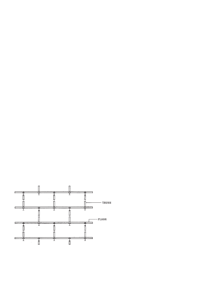
The staggered-truss framing system, originally developed at
MIT in the 1960s, has been used as the major structural sys-
tem for certain buildings for some time. This system is effi-
cient for mid-rise apartments, hotels, motels, dormitories,
hospitals, and other structures for which a low floor-to-floor
height is desirable. The arrangement of story-high trusses in
a vertically staggered pattern at alternate column lines can
be used to provide large column-free areas for room layouts
as illustrated in Fig. 1.1. The staggered-truss framing sys-
tem is one of the only framing system that can be used to
allow column-free areas on the order of 60 ft by 70 ft. Fur-
thermore, this system is normally economical, simple to
fabricate and erect, and as a result, often cheaper than other
framing systems.
One added benefit of the staggered-truss framing system
is that it is highly efficient for resistance to the lateral load-
ing caused by wind and earthquake. The stiffness of the sys-
tem provides the desired drift control for wind and
earthquake loadings. Moreover, the system can provide a
significant amount of energy absorption capacity and duc-
tile deformation capability for high-seismic applications.
When conditions are proper, it can yield great economy and
maximum architectural and planning flexibility.
It also commonly offers the most cost-efficient possibili-
ties, given the project’s scheduling considerations. The
staggered-truss framing system is one of the quickest avail-
able methods to use during winter construction. Erection
and enclosure of the buildings are not affected by prolonged
sub-freezing weather. Steel framing, including spandrel
beams and precast floors, are projected to be erected at the
rate of one floor every five days. Once two floors are
erected, window installation can start and stay right behind
the steel and floor erection. No time is lost in waiting for
other trades such as bricklayers to start work. Except for
foundations and grouting, all “wet” trades are normally
eliminated.
Savings also occur at the foundations. The vertical loads
concentrated at a few columns normally exceed the uplift
forces generated by the lateral loads and, as a result, uplift
anchors are often not required. The reduced number of
columns also results in less foundation formwork, less con-
crete, and reduced construction time. When used, precast
plank is lighter then cast-in-place concrete, the building is
lighter, the seismic forces are smaller, and the foundations
are reduced.
The fire resistance of the system is also good for two rea-
sons. First, the steel is localized to the trusses, which only
occur at every 58 to 70 ft on a floor, so the fireproofing
operation can be completed efficiently. Furthermore, the
trusses are typically placed within demising walls and it is
possible that the necessary fire rating can be achieved
through proper construction of the wall. Also, the elements
of the trusses are by design compact sections and thus will
require a minimum of spray-on fireproofing thickness.
1.2 Material Description
A staggered-truss frame is designed with steel framing
members and concrete floors. Most often, the floor system
is precast concrete hollow-core plank. Other options,
including concrete supported on metal deck with steel
beams or joists, can be used.
With precast plank floors, economy is achieved by
“stretching” the plank to the greatest possible span. 8-in.-
thick plank generally can be used to span up to 30 ft, while
10-in.-thick plank generally can be used to span up to 36 ft.
Specific span capabilities should be verified with the spe-
cific plank manufacturer. Therefore, the spacing of the
trusses has a close relationship to the thickness of plank and
its ability to span. 6-in.-thick precast plank is normally only
used with concrete topping.
Hollow core plank is manufactured by the process of
extrusion or slip forming. In both cases the plank is pre-
stressed and cambered. The number of tendons and their
diameter is selected for strength requirements by the plank
manufacturer’s engineer based upon the design instructions
provided by the engineer of record.
The trusses are manufactured from various steels. Early
buildings were designed with chords made of wide-flange
sections and diagonal and vertical members made of chan-
Chapter 1
INTRODUCTION
Fig. 1.1 Staggered-truss system-vertical stacking arrangement.
2
nels. The channels were placed toe-to-toe, welded with sep-
arator plates to form a tubular shape. Later projects used
hollow structural sections (HSS) for vertical and diagonal
members.
Today, the most common trusses are designed with W10
chords and HSS web members (verticals and diagonals)
connected with gusset plates. The chords have a minimum
width of 6 in., required to ensure adequate plank bearing
during construction. The smallest chords are generally
W10x33 and the smallest web members are generally
HSS4
×4×¼. The gusset plates are usually ½-in. thick.
The trusses are manufactured with camber to compensate
for dead load. They are transported to the site, stored, and
then erected, generally in one piece. Table 1.1 is a material
guide for steel member selection. Other materials, such as
A913, may be available (see AISC Manual, Part 2).
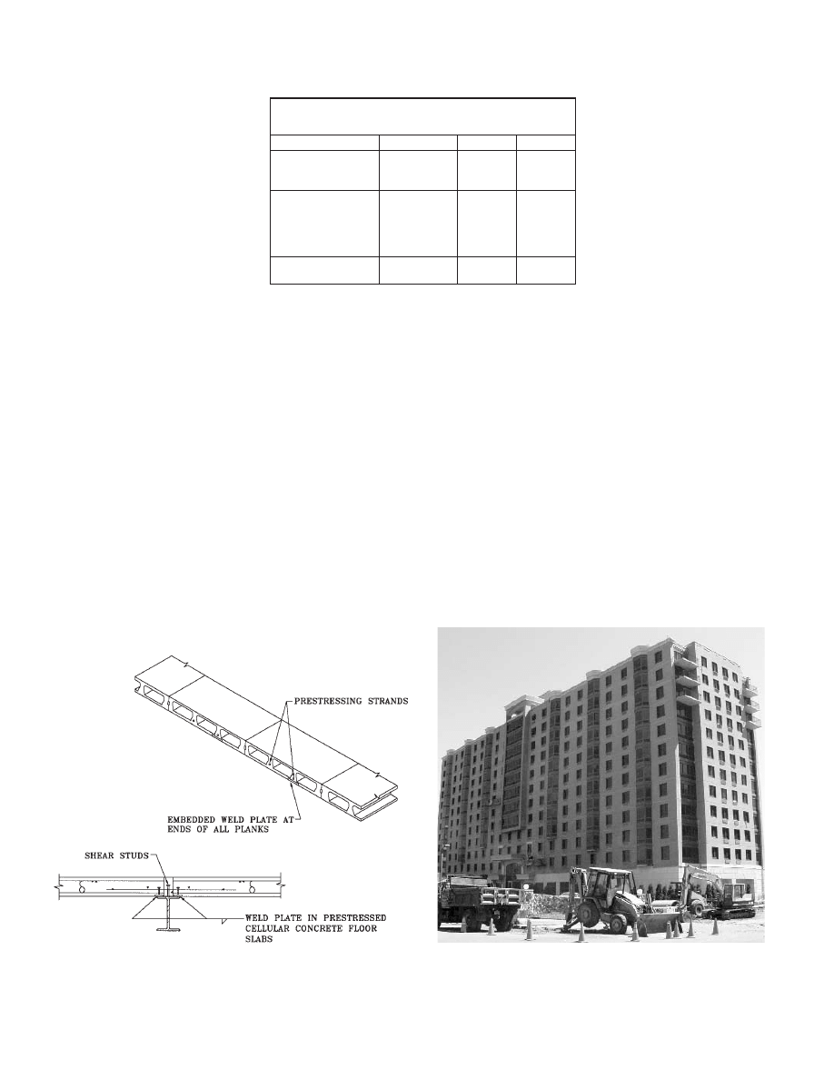
The plank is connected to the chords with weld plates to
ensure temporary stability during erection. Then, shear stud
connections are welded to the chords, reinforcing bars are
placed in the joints, and grout is placed. When the grout
cures, a permanent connection is achieved through the
welded studs as illustrated in Fig. 1.2. Alternatively, guying
or braces may also be used for temporary stability during
construction.
The precast plank is commonly manufactured with 4,000
psi concrete. The grout commonly has 1,800 psi compres-
sive strength and normally is a 3:1 mixture of sand and
Portland cement. The amount of water used is a function of
the method used to place the grout, but will generally result
in a wet mix so joints can be easily filled. Rarely is grout
strength required in excess of 2,000 psi. The grout material
is normally supplied and placed by the precast erector.
1.3 Framing Layout
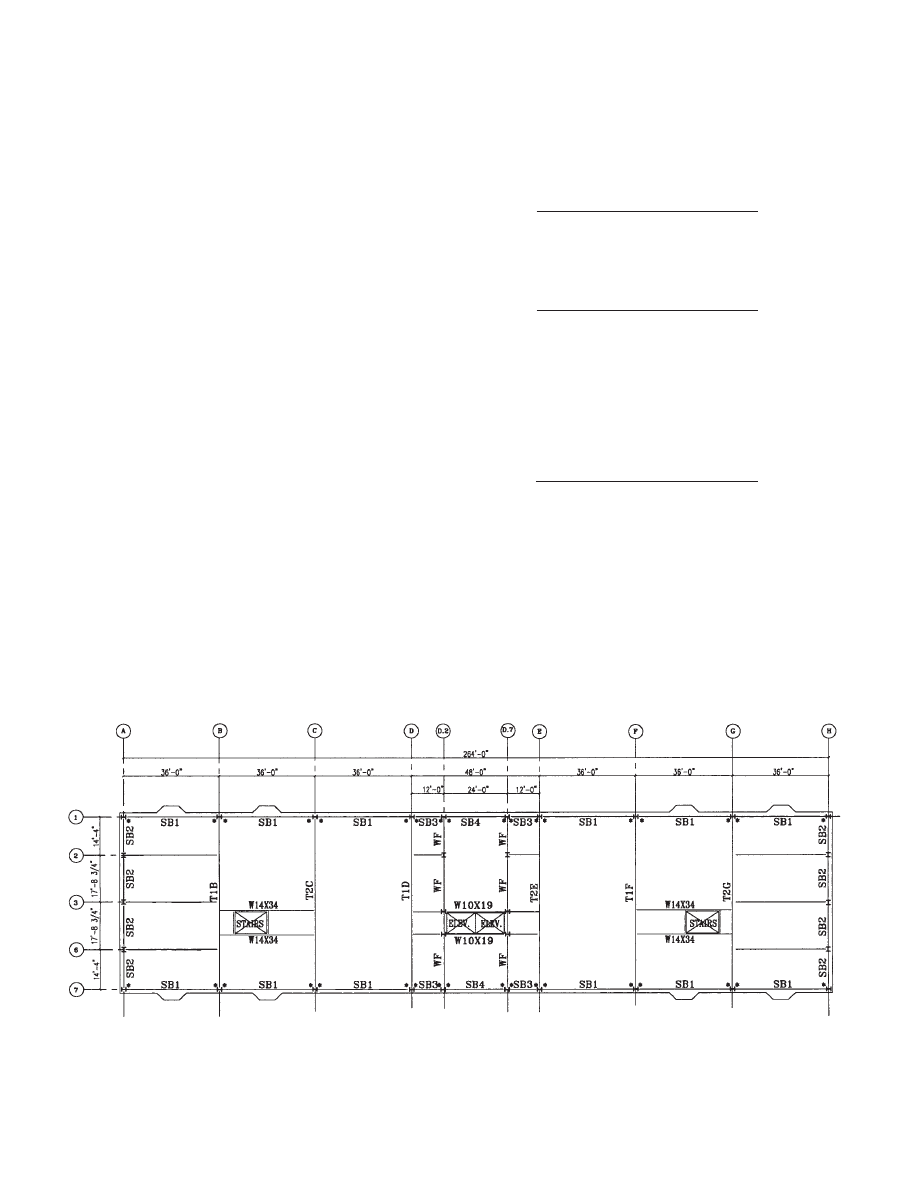
Fig. 1.3 shows the photo of a 12-story staggered-truss apart-
ment building located in the Northeast United States. Its
typical floor plan is shown in Fig. 1.4. This apartment build-
ing will be used as an example to explain the design and
construction of staggered-truss-framed structures through-
out this design guide. The floor system of this 12-story proj-
Fig. 1.2 Concrete plank floor system.
Table 1.1 Material Guide
Section
ASTM
Fy (ksi)
Columns and Truss
Chords
Wide Flange
A992 or
A572
50
Web Members
(Vertical and Diagonal)
Hollow Structural
Section
A500 grade
B or C
46 or 50
(rectangular)
Gusset Plates
Plates
A36 or A572
36 or 50
Fig. 1.3 Staggered truss apartment building.
3
ect utilizes 10-in.-thick precast concrete plank. The stairs
and elevator openings are framed with steel beams. The
columns are oriented with the strong axis parallel to the
short building direction. There are no interior columns on
truss bents; only spandrel columns exist. There are interior
columns on conventionally framed bents.
Moment frames are used along the long direction of the
building, while staggered trusses and moment frames are
used in the short direction.
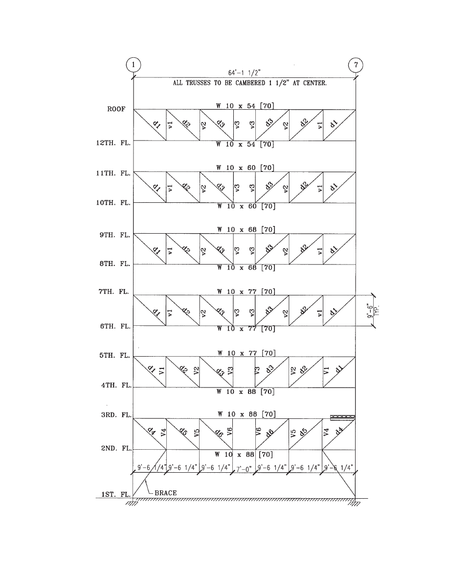
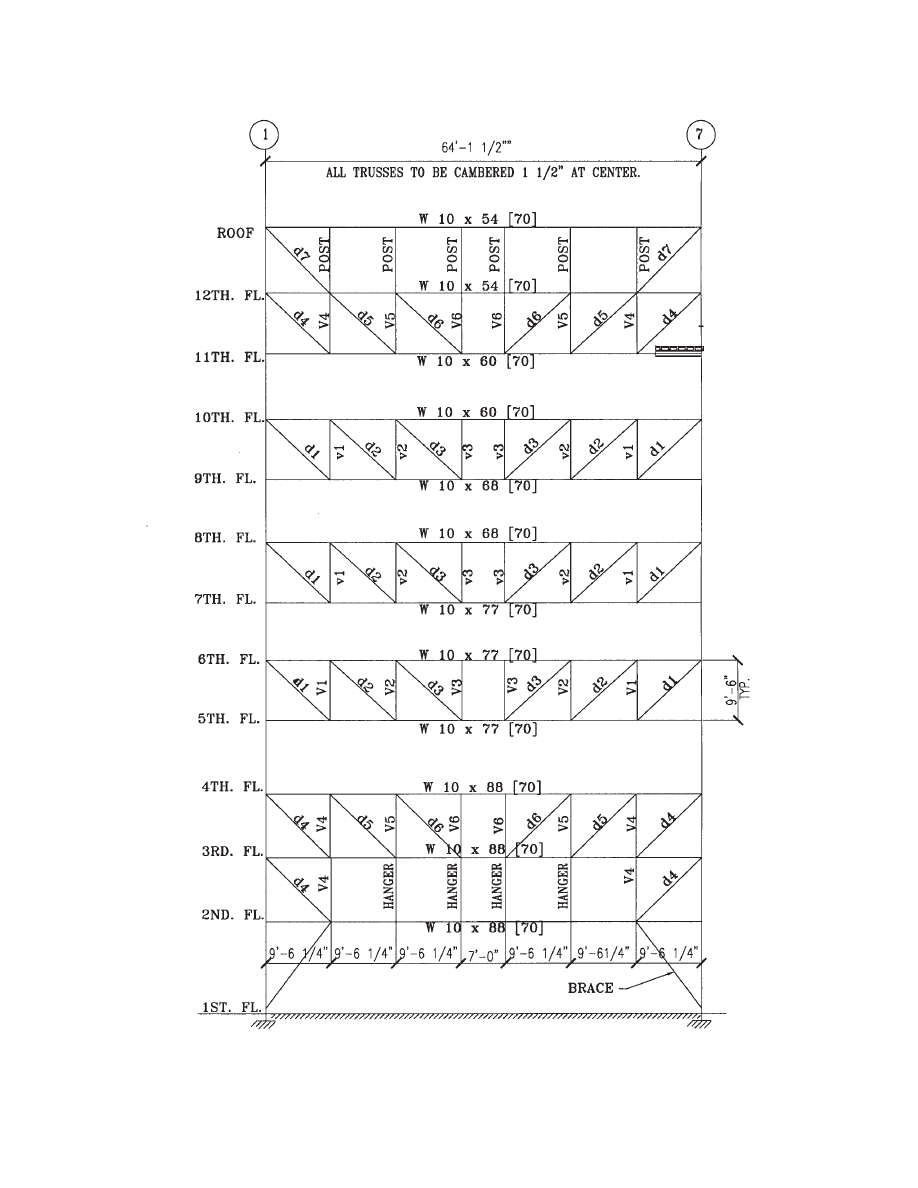
Two different truss types are shown on the plan, namely
trusses T1 and T2. Fig. 1.5 shows truss T1B and Fig. 1.6
shows truss T2C. Truss T1B is Truss Type 1 located on grid
line B, and T2C is Truss Type 2 located on grid line C. The
truss layout is always Truss Type 1 next to Type 2 to mini-
mize the potential for staggered truss layout errors. Each
truss is shown in elevation in order to identify member sizes
and special conditions, such as Vierendeel panels. Any spe-
cial forces or reactions can be shown on the elevations
where they occur. The structural steel fabricator/detailer is
provided with an explicit drawing for piece-mark identifi-
cation. Camber requirements should also be shown on the
elevations.
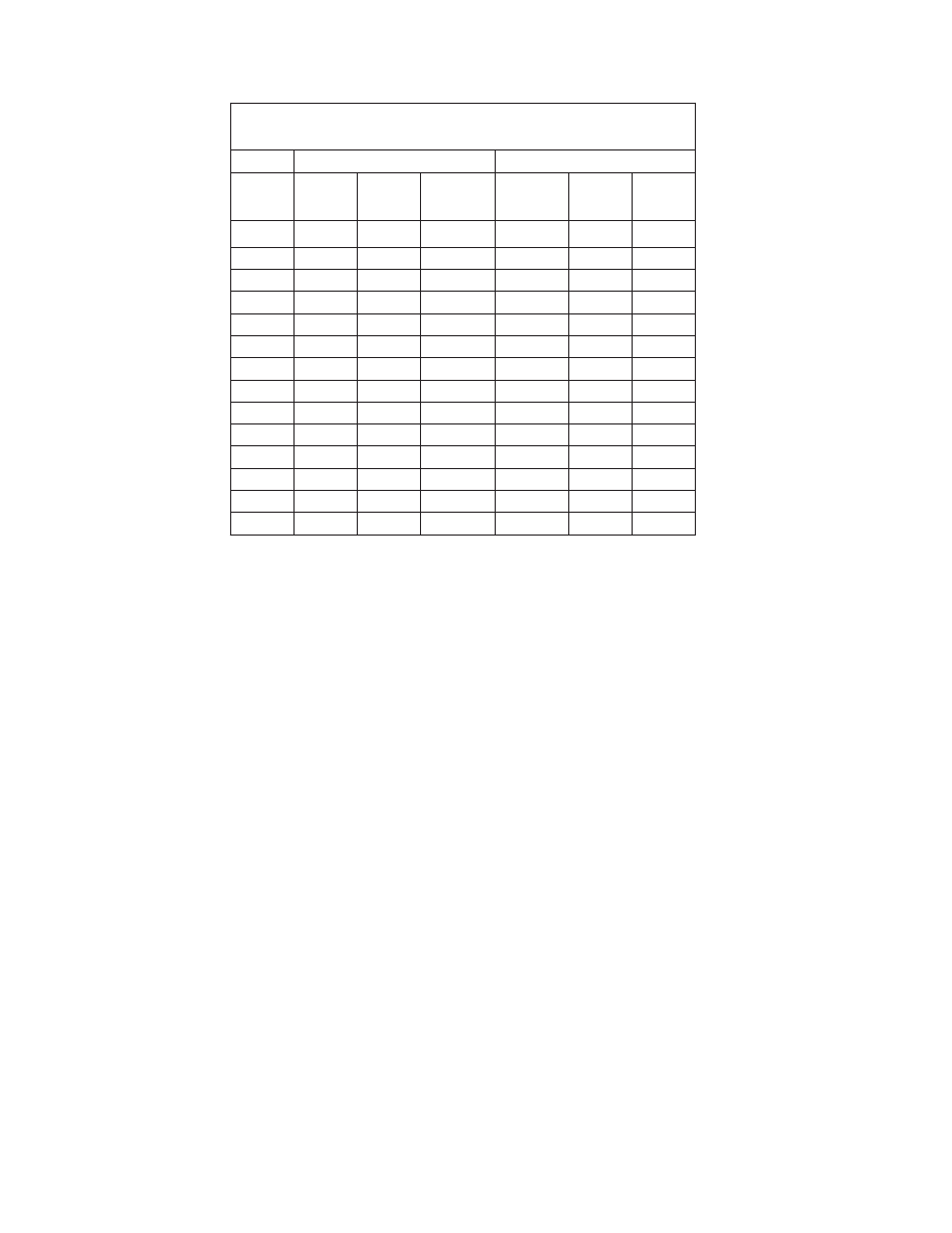
Table 1.2 shows the lateral forces calculated for the
building. For this building, which is located in a low-seis-
mic zone, wind loads on the wide direction are larger than
seismic forces, and seismic forces are larger in the narrow
direction. So that no special detailing for seismic forces
would be required, a seismic response modification factor R
of 3 was used in the seismic force calculations. The distrib-
uted gravity loads of the building are listed below, where
plate loads are used for camber calculations.
Dead Loads
10” precast hollow core plank
75 psf
Leveling compound
5
Structural steel
5
Partitions 12
Dead Loads
97 psf
Plate Loads
10” precast hollow core plank
75 psf
Structural steel
5
Plate Loads
80 psf
Live Loads
40 psf
Wall Loads
Brick
40 psf
Studs
3
Sheet rock
3
Insulation
2
Wall Loads
48 psf
The loads listed above are used in the calculations that
follow.
1.4 Responsibilities
The responsibilities of the various parties to the contract are
normally as given on the AISC Code of Standard Practice
for Steel Buildings and Bridges. All special conditions
should be explicitly shown on the structural drawings.
Fig. 1.4 Typical floor framing plan. Note: * indicates moment connections.
4
1.5 Design Methodology
The design of a staggered-truss frame is done in stages.
After a general framing layout is completed, gravity, wind,
and seismic loads are established. Manual calculations and
member sizing normally precede the final computer analy-
sis and review. For manual calculations, gravity and lateral
loads are needed and the member sizes are then obtained
through vertical tabulation.
The design methodology presented in this design guide is
intended to save time by solving a typical truss only once
for gravity loads and lateral loads, then using coefficients to
obtain forces for all other trusses. The method of coeffi-
cients is suitable for staggered trusses because of the repe-
tition of the truss geometry and because of the “racking” or
shearing behavior of trusses under lateral loads. This is sim-
ilar to normalizing the results to the “design truss”.
Approximate analysis of structures is needed even in
today’s high-tech computer world. At least three significant
reasons are noted for the need for preliminary analysis as
following:
1. It provides the basis for selecting preliminary member
sizes, which are needed for final computer input and
verification.
2. It provides a first method for computing different
designs and selecting the preferred one.
3. It provides an independent method for checking the
reports from a computer output.
Theoretically, staggered-truss frames are treated as struc-
turally determinate, pin-jointed frames. As such, it is
assumed that no moment is transmitted between members
across the joints. However, the chords of staggered trusses
are continuous members that do transmit moment, and
some moment is always transmitted through the connec-
tions of the web members.
The typical staggered-truss geometry is that of a “Pratt
truss” with diagonal members intentionally arranged to be
in tension when gravity loads are applied. Other geome-
tries, however, may be possible.
1.6 Design Presentation
The structural drawings normally include floor framing
plans, structural sections, and details. Also, structural notes
and specifications are part of the contract documents. Floor
plans include truss and column layout, stairs and elevators,
dimensions, beams, girders and columns, floor openings,
section and detail marks. A column schedule indicates col-
umn loads, column sizes, location of column splices, and
sizes of column base plates.
The diaphragm plan and its chord forces and shear con-
nectors with the corresponding forces must be shown. It is
also important that the plan clearly indicate what items are
the responsibilities of the steel fabricator or the plank man-
ufacturer. Coordination between the two contractors is crit-
ical, particularly for such details as weld plate location over
stiffeners, plank camber, plank bearing supports, and clear-
ances for stud welding. Coordination meetings can be par-
ticularly helpful at the shop drawing phase to properly
locate plank embedded items.
In seismic areas, the drawings must also indicate the
Building Category, Seismic Zone, Soil Seismic Factor,
Importance Factor, required value of R, and Lateral Load
Resisting System.
Table 1.2 Wind and Seismic Forces
(All Loads are Service Loads)
WIND (ON WIDE DIRECTION)
SEISMIC (BOTH DIRECTIONS)
Lateral
Load
Story
Shear
Φ
Φ
h
Lateral Load
Service
Story
Shear
Φ
Φ
h
Floor
V
j
(kips)
V
w
(kips)
(%)
Vj (kips)
Vw (kips)
(%)
Roof
107
107
9%
83
83
13%
12
105
212
18%
90
173
26%
11
103
315
27%
82
255
39%
10
103
418
36%
78
333
51%
9
103
521
45%
65
398
61%
8
98
619
54%
58
456
70%
7
96
715
62%
52
5
0
8
78%
6
93
808
70%
44
552
85%
5
91
899
78%
39
591
91%
4
86
985
86%
29
620
95%
3
84
1069
93%
21
641
98%
2
79
1148
100%
11
652
100%
Ground
5
Fig. 1.5 Staggered truss type T1B. Note: [ ] indicates number of composite studs (¾” dia., 6” long, equally spaced).
6
Fig. 1.6 Staggered truss type T2C. Note: [ ] indicates number of composite studs (¾” dia., 6” long, equally spaced).
7
2.1 General Information
It is advisable to start the hand calculations for a staggered-
truss building with the design of the diaphragms. In a stag-
gered-truss building, the diaphragms function significantly
different from diaphragms in other buildings because they
receive the lateral loads from the staggered trusses and
transmit them from truss to truss. The design issues in a
hollow-core diaphragm are stiffness, strength, and ductility,
as well as the design of the connections required to unload
the lateral forces from the diaphragm to the lateral-resisting
elements. The PCI Manual for the Design of Hollow Core
Slabs (PCI, 1998) provides basic design criteria for plank
floors and diaphragms.
Some elements of the diaphragm design may be dele-
gated to the hollow core slab supplier. However, only the
engineer of record is in the position to know all the param-
eters involved in generating the lateral loads. If any design
responsibility is delegated to the plank supplier, the location
and magnitude of the lateral loads applied to the diaphragm
and the location and magnitude of forces to be transmitted
to lateral-resisting elements must be specified.
An additional consideration in detailing diaphragms is
the need for structural integrity. ACI 318 Section 16.5 pro-
vides the minimum requirements to satisfy structural
integrity. The fundamental requirement is to provide a com-
plete load path from any point in a structure to the founda-
tion. In staggered-truss buildings all the lateral loads are
transferred from truss to truss at each floor. The integrity of
each floor diaphragm is therefore significant in the lateral
load resistance of the staggered-truss building.
2.2 Distribution of Lateral Forces
The distribution of lateral forces to the trusses is a struc-
turally indeterminate problem, which means that deforma-
tion compatibility must be considered. Concrete
diaphragms are generally considered to be rigid. Analysis
of flexible diaphragms is more complex than that of rigid
diaphragms. However, for most common buildings subject
to wind forces and low-seismic risk areas, the assumption
of rigid diaphragms is reasonable. If flexible diaphragms
are to be analyzed, the use of computer programs with
plate-element options is recommended.
For the example shown in this design guide, a rigid
diaphragm is assumed for the purpose of hand calculations
and for simplicity. This assumption remains acceptable as
long as the diaphragm lateral deformations are appropri-
ately limited. One way to ensure this is to limit the
diaphragm aspect ratio and by detailing it such that it
remains elastic under applied loads. From Smith and Coull
(1991), the lateral loads are distributed by the diaphragm to
trusses as follows:
V
i
= V
s
+ V
TORS
(2-1)
where
V
i
= truss shear due to lateral loads
V
s
= the translation component of shear
= V
w
× GA
i
/
ΣGA
i
(2-2)
V
TORS
= the torsion component of shear
= V
w
× e GA
i
/ GJ
(2-3)
where
GA
i
= Shear rigidity of truss
ΣGA
i
= Building translation shear rigidity
GJ
= Building torsion shear rigidity
e
= Load eccentricity
= Truss coordinate (referenced to the
center of rigidity (CR))
V
w
= Story shear due to lateral loads
(see Table 1.2)
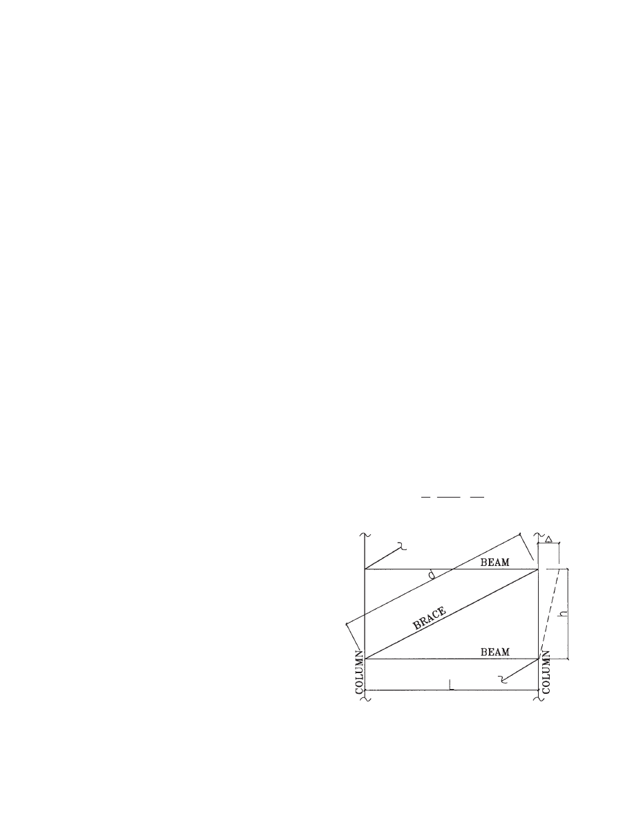
Smith and Coull (1991) provide expressions for story
shear deformations for a single brace as (Fig. 2.1):
Chapter 2
DIAPHRAGM ACTION WITH HOLLOW-CORE SLABS
Fig. 2.1 Story shear deformation for single brace.
3
2
g
d
V
d
L
E
A
L A
⎛
⎞
∆ =
+
⎜
⎟
⎝
⎠
(2-4)
x
i
⎯
x
i
⎯
8
where
V = shear force applied to the brace
E = modulus of elasticity
d
= length of the diagonal
L
= length between vertical members
A
d
= sectional area of the diagonal
A
g
= sectional area of the upper girder
The shear rigidity GA is then computed as:
where h is the story height. The overall truss shear rigidity
is the sum of the shear rigidities of all the brace panels in
that truss. The reader may use similar expressions to deter-
mine approximate values for GA in buildings where varia-
tions in stiffness occur.
The hand calculations are started by finding the center of
rigidity, which is defined as the point in the diaphragm
about which the diaphragm rotates when subject to lateral
loads. The formula for finding the center of rigidity is
(Smith and Coull, 1991; Taranath, 1997):
x =
Σx
i
GA
i
/
ΣGA
i
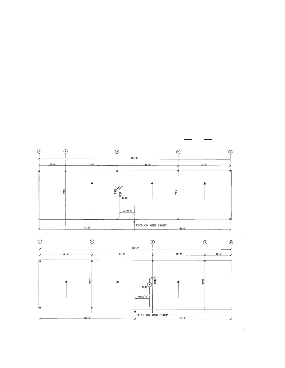
For staggered-truss buildings, the center of rigidity is cal-
culated separately at even floors and odd floors. Assuming
that the trusses of the staggered-truss building shown in
Figs. 1.5 and 1.6 have approximately equal shear rigidity,
GAi, per truss, the center of rigidity of each floor is calcu-
lated as follows (see Fig. 2.2):
Even Floors
Truss
x
i
(ft)
T1B
36
T1D
108
T1F
192
Σx
i
= 336
x
e
= 336/3 = 112'
3
2
/(
)
/
d
g
V h
E h
GA
d
L A
L A
=
=
∆
+
(2-5)
(2-6)
(a)—Even Floor
(b)—Odd Floor
Fig. 2.2 Center of rigidity for lateral loads.

9
where x
e
is the center of rigidity for even floors.
Odd Floors
Truss
x
i
(ft)
T2C
72
T2E
156
T2G
228
Σx
i
= 456
x
o
= 456/3 = 152'
where x
o
is the center of rigidity for odd floors. The load
eccentricity is calculated as the distance between the center
of rigidity and the location of the applied load.
e
e
= (264/2)
− 112 = 20'
even floors
e
o
= (264/2)
− 152 = −20'
odd floors
Adding 5% eccentricity for accidental torsion, the final
load eccentricity is calculated as follows:
e
e
= 20 ± (5%
× 264)
= 33.2; 6.8 ft
e
o
=
−20 ± (5% × 264)
=
−33.2; −6.8 ft
From this it is clear that for this example even and odd
floors are oppositely symmetrical. The base torsion is cal-
culated as the base shear times the eccentricity:
T = 1,148
× 33.2 = 38,114 ft-k
T = 1,148
× 6.8 = 7,807 ft-k
where the base shear of 1,148 k is from Table 1.2. The
above torsions have plus and minus signs. Again assuming
that all trusses have the same shear rigidity GA
i
at each
floor, the base translation shear component is the same for
all trusses:
V
s
= 1,148/3 = 383 k
Next, the torsional rigidity GJ is calculated as shown in
Tables 2.1 and 2.2 for even floors and odd floors. The tor-
sional shear component varies and is added or subtracted to
the translational shear component. The results are summa-
rized in Table 2.3, which is obtained by using Equations 2-1,
2-2, and 2-3. The second-to-last column in Table 2.3 shows
the design forces governing the truss design. Note that the
design shear for the trusses is based on
+5% or −5% eccen-
tricity, where * indicates the eccentricity case that governs.
Table 2.3 also shows that the design base shear for trusses
T1B and T2G is 335 k, for trusses T1D and T2E is 380 k,
and for trusses T1F and T2C is 634 k. We can now proceed
with the truss design for lateral loads, but we will first con-
tinue to analyze and design the diaphragm.
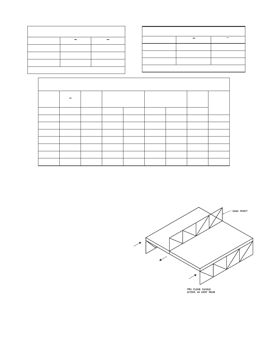
2.3 Transverse Shear in Diaphragm
Planks are supported on trusses with longitudinal joints
perpendicular to the direction of the applied lateral load. To
satisfy structural integrity, the diaphragm acts as a deep
beam or a tied arch. Tension and compression chords create
the flanges, and boundary elements are placed around the
openings. The trusses above are considered to act as “drag
struts”, engaging the entire length of the diaphragm for
transferring shear to the adjacent trusses below (Fig. 2.3).
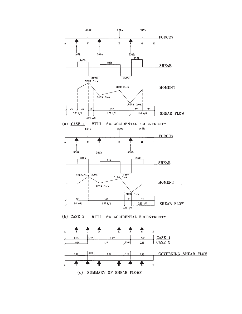
Truss shear forces calculated in Table 2.3 are used to find
the shear and moment diagrams along the diaphragm of the
bottom floor as shown in Fig. 2.4. Two torsion cases (
+5%
and
−5% additional eccentricities) are considered. The
required shear strength of the diaphragm is calculated as
follows:
where
φ
h
is the story shear adjustment coefficient (see Table
1.2 and Section 3.5 of this design guide), 0.75 is applied for
wind or seismic loads, and V = 335 k is the maximum shear
force in the diaphragm as indicated in Fig. 2.4. The pro-
vided design shear strength is calculated per ACI 318 Sec-
tion 11.3.
where an effective thickness of 6 in. is used for the 10-in.-
thick hollow core planks, and the effective depth of the
beam is assumed to be 80% of the total depth.
φV
s
=
φA
VF
f
y
µ
where A
VF
is the shear friction reinforcement and
µ = 1.4 is
the coefficient of friction. Assuming one #4 steel bar is used
along each joint between any two planks,
No. of planks = 64'/8' = 8 planks
No. of joints = 8
− 1 = 7 joints
A
VF
= 0.2
× 7 = 1.4 in
2
φV
s
= 0.85
× 1.4 × 60 × 1.4 = 100 k
φV
n
= 396
+ 100 = 496 k > 427 k
(O.K.)
1.7
0.75
1.7 1.0 335 0.75
427k
u
h
V
V
=
× φ × ×
=
×
×
×
=
(
)
(
)
2
0.85 2
4000
6
0.8 64 12
396k
n
c
s
c
c
V
V
V
V
f bd
φ = φ
+
′
φ = φ ×
=
× ×
× ×
×
×
=
10
2.4 Diaphragm Chords
The perimeter steel beams are used as diaphragm chords.
The chord forces are calculated approximately as follows:
H = M/D
(2-7)
where
H = chord tension or compression force
M = moment applied to the diaphragm
D = depth of the diaphragm
The plank to spandrel beam connection must be adequate
to transfer this force from the location of zero moment to
the location of maximum moment. Thus observing the
moment diagrams in Fig. 2.4, the following chord forces
and shear flows needed for the plank-to-spandrel connec-
tion design are calculated:
With
+5% additional eccentricity:
H = 5,223 / 64
× 0.75
= 61 k
f
H
= 61 / 72
= 0.85 k/ft
H = 5,223 / 64
× 0.75
= 61 k
f
H
= 61 /17
= 3.59 k/ft
H = 12,024 / 64
× 0.75 = 141 k
f
H
= 141 / 103
= 1.37 k/ft
f
H
= 141 / 72
= 1.96 k/ft
where constant 0.75 is applied for wind or seismic loads.
The calculated shear flows, f
H
, are shown in Fig. 2.4(a). For
−5% additional eccentricity, similar calculations are con-
ducted and the results are shown in Fig. 2.4(b). The shear
flows of the two cases are combined in Fig. 2.4(c), where a
Table 2.3 Shear Force in Each Truss due to Lateral Loads (Bottom Floor)
x
i
V
s
T=38,114 (ft-k)
T=7,807 (ft-k)
Design
Shear
V (kips)
Truss
V
TORS
V
i
V
TORS
V
i
V
i
Φ
Φ
ecc
T1B
-76
383
-238
145
-48
335*
335
1.00
T1D
-4
383
-13
370
-3
380*
380
1.13
T1F
80
383
251
634*
51
434
634
1.89
T2C
-80
383
251
634*
51
434
634
1.89
T2E
4
383
-13
370
-3
380*
380
1.13
T2G
76
383
-238
145
-48
335*
335
1.00
Table 2.1 Torsional Rigidity, Even Floors
Truss
x
i
x
i
2
T1B
-76
5,776
T1D
-4
16
T1F
80
6,400
Σ=12,192 ft
2
Table 2.2 Torsional Rigidity, Odd Floors
Truss
x
i
x
i
2
T2C
-80
6,400
T2E
4
16
T2G
76
5,776
Σ=12,192 ft
2
Fig. 2.3 Diaphragm acting as a deep beam.

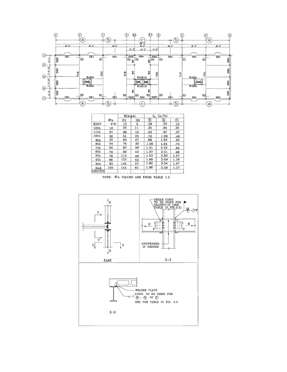
11
The connections of the beams to the columns must develop
these forces (H). The plank connections to the spandrel
beams must be adequate to transfer the shear flow, f
H
. The
plank connections to the spandrel are usually made by shear
plates embedded in the plank and welded to the beams (Fig.
1.2 and Fig. 2.6). Where required, the strength of plank
embedded connections is proven by tests, usually available
from the plank manufacturers. All forces must be shown on
the design drawings. The final design of the diaphragm is
shown in Fig. 2.5.
value with * indicates the larger shear flow that governs.
These shear forces and shear flows due to service loads on
the bottom floor are then multiplied by the height adjust-
ment factors for story shear to obtain the final design of the
diaphragms up to the height of the building as shown in the
table in Fig. 2.5. The table is drawn on the structural draw-
ings and is included as part of the construction contract doc-
uments. Forces given on structural drawings are generally
computed from service loads. In case factored forces are to
be given on structural drawings, they must be clearly spec-
ified.
The perimeter steel beams must be designed to support
the gravity loads in addition to the chord axial forces, H.
12
Fig. 2.4 Diaphragm shear force, moment, and shear flow (2
nd
floor).
13
Fig. 2.5 Diaphragm design.
Fig. 2.6 Detail for load transfer from diaphragm to spandrel beams.

14

15
3.1 Hand and Computer Calculations
The structural design of truss members normally begins
with hand calculations, which are considered to be approx-
imate and prerequisite to more detailed computer calcula-
tions. Computer analyses can be either two or three
dimensional using stiffness matrix methods with or without
member sizing. Some programs assume a rigid diaphragm
and the lateral loads are distributed based on the relative
stiffness of the trusses. In other programs, the stiffness of
the diaphragm can be modeled with plate elements.
For truss design, hand and computer calculations have
both advantages and disadvantages. For symmetrical build-
ings, 2-D analysis and design is sufficient and adequate. For
non-symmetrical structures, 3-D analyses in combination
with 2-D reviews are preferred. The major advantage of a
2-D analysis and design is saving in time. It is fast to model
and to evaluate the design results.
Hand calculations typically ignore secondary effects
such as moment transmission through joints, which may
appear to produce unconservative results. However, it is
worthwhile to remember that some ductile but self-limiting
deformations are allowed and should be accepted.
3.2 Live Load Reduction
Most building codes relate the live load reduction to the
tributary area each member supports. For staggered trusses
this requirement creates a certain difficulty since the tribu-
tary areas supported by its vertical and diagonal members
vary. Some engineers consider the entire truss to be a single
member and thus use the same maximum live load reduc-
tion allowed by code for all the truss members. Others cal-
culate the live load reduction on the basis of the equivalent
tributary area each member of the truss supports. Clearly,
member d1 in Fig. 1.5, which carries a heavy load, supports
an equivalent tributary area larger than that of member d3,
which carries a light load. Thus, assuming that web mem-
bers support equivalent floor areas, the following tributary
area calculations apply:
d1: TA = (7/2 + 9.5
× 2 + 9.5/2) 36 × 2
= 1,960 ft
2
d2: TA = (7/2 + 9.5 + 9.5/2) 36
× 2
= 1,278 ft
2
d3: TA = (7/2 + 9.5/2) 36
× 2
= 594 ft
2
These tributary areas can also be verified from the mem-
ber loads as follows. Thus, considering the entire truss T1B,
the tributary area is:
TA = 64
× 36 × 2 = 4,608 ft
2
The total dead load supported by the truss is:
W
DL
= 4,608
× 97 psf = 446.7 k
For member d1:
Axial force T = 380 k
× 97/(97 + 40)
= 269 k (see Fig. 3.3)
Vertical component of T = 269/
= 190 k
TA = 190 / 446.7
× 4,608 = 1,960 ft
2
This tributary area is the same as the one calculated pre-
viously. Similar calculations yield the tributary areas for
members d2 and d3.
3.3 Gravity Loads
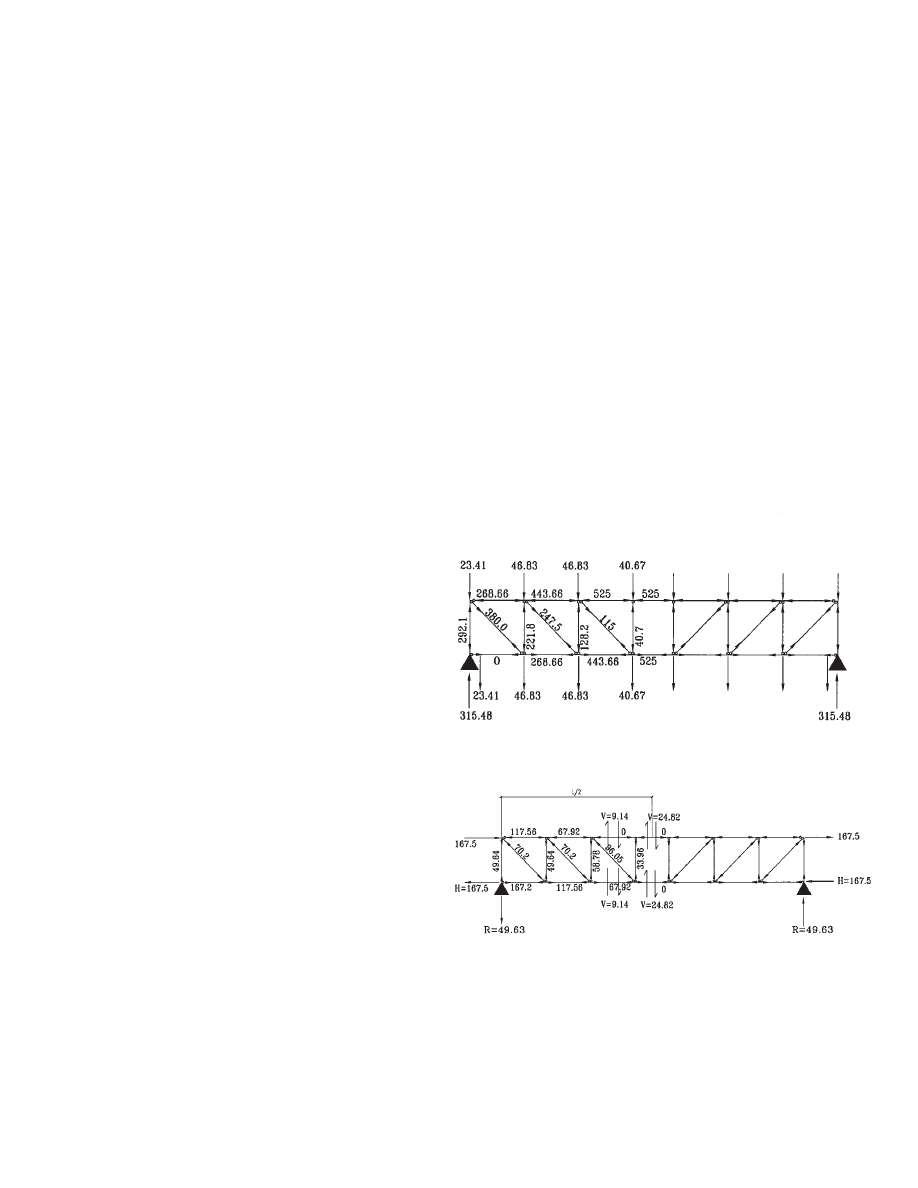
Fig. 3.1 shows a one-story truss with applied gravity loads.
The members are assumed to intersect at one point. The ver-
tical and diagonal members are assumed to be hinged at
each end. The top and bottom chords are continuous beams
and only hinged at the ends connected to the columns.
Because a diagonal member is not allowed to be placed in
the Vierendeel panel where a corridor is located, the chords
cannot be modeled as axial-force members. Otherwise, the
truss would be unstable. For hand calculation purposes, it
Chapter 3
DESIGN OF TRUSS MEMBERS
2
Fig. 3.1 Analysis of truss T1B—gravity loads.
16
is customary to convert the uniform loads to concentrated
loads applied at each joint. It will be shown later that shear
forces in the chords have to be included in the hand calcu-
lations when lateral loads are applied. The chords are sub-
ject to bending and shear, but the vertical and diagonal
members are not because they are two-force members.
The truss model shown is “statically indeterminate”. The
truss can certainly be analyzed using a computer. However,
reasonably accurate results can also be obtained through
hand calculations. For gravity loads, the shear force in the
top or bottom chord in the Vierendeel panel vanishes
because of symmetry. The shear forces in the chords of
other panels are very small and can be neglected. Based on
this assumption, the truss becomes statically determinate
and the member forces can be calculated directly by hand
calculations from statics. The best way to start the calcula-
tions is by finding the reactions at the supports. After the
reactions are determined, there are two different options for
the further procedure.
a. The method of joints.
b. The method of sections.
The reader is referred to Hibbeler (1998) or Hsieh (1998)
or any other statics textbook for in-depth discussion of each
method. Each method can resolve the truss quickly and pro-
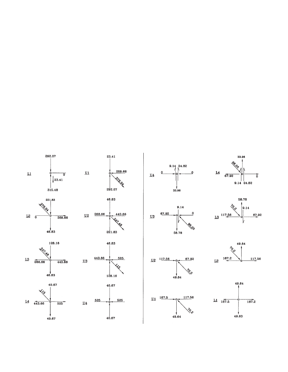
vide the correct solution. Fig. 3.2 shows the truss solution
using the method of joints. It is best to progress the solution
in the following joint order: L1, U1, L2, U2, etc. The fol-
lowing calculations are made for typical truss T1B subject
to full service gravity loads:
w
= (97 psf + 40 psf)
× 36' = 4.93 k/ft
P
1
= 4.93
× 9.5 / 2 = 23.41 k
P
2
= 4.93
× 9.5' = 46.83 k
P
3
= 4.93
× (9.5 + 7)/2 = 40.67 k
The above concentrated loads are applied at the top and
bottom joints as shown in Fig. 3.1. The reactions at sup-
ports are:
GRAVITY LOADS (KIPS)
LATERAL LOADS (KIPS)
Fig. 3.2 Truss solution—method of joints.
17
R
= (23.41 + 46.83
× 2 + 40.67) × 2
= 315.48 k
The calculations then proceed for each joint as shown in
Fig. 3.2. Here shear forces in the chord members are
excluded from the calculations because they are assumed
zero. The result of all the member forces of the typical truss
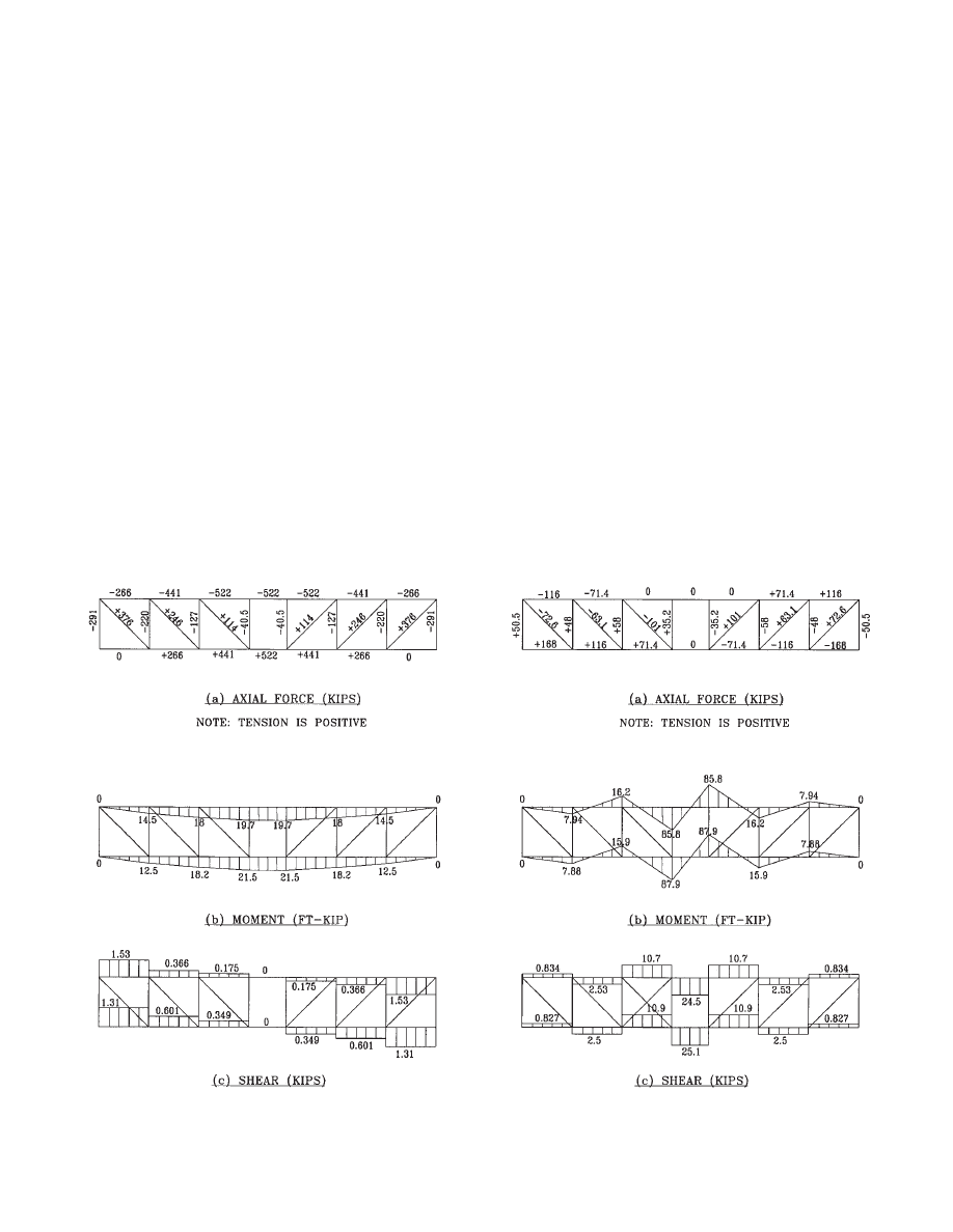
due to service gravity loads is summarized in Fig. 3.3.
3.4 Lateral Loads
The allocation of lateral loads to each individual truss is
done by the diaphragm based on the truss relative stiffness
and its location on the plan. Once the member forces due
to lateral loads are calculated, they are combined with the
gravity loads to obtain the design-loading envelope. The
member sizes are then selected to ensure adequate strength.
Fig. 3.4 shows the member forces due to design shear of
335 kips, which was computed in Table 2.3 for truss T1B of
the bottom floor. Because the truss is anti-symmetrical
about its centerline for this load case, the horizontal reac-
tion H at each support is 167.5 kips. Alternatively, the floor
diaphragm may distribute the horizontal shear force uni-
formly along the length of the top and bottom chords of the
truss, reducing the axial forces in these chords. The vertical
reaction at each support is:
R = (167.5
× 2 × 9.5) / 64.125 = 49.63 k
The moment and the axial force at midspan of each chord
in the Vierendeel panel are both zero because of geometri-
cal anti-symmetry. Considering half of the truss as a free
body and assuming the same shear force in the top and bot-
tom chords of the Vierendeel panel, the shear force can be
calculated as:
V = 1 / 2
× (167.5 × 9.5) / 32.06
= 24.82 k
The chord end moment at joint U4 is equal to the shear
times half the panel length:
M = 24.82
× 7 / 2 = 86.87 ft-k
This end moment is also applied to the chord adjacent to
the Vierendeel panel. Assume the moment at the other end
of this chord is zero, the shear force in the member can then
be calculated as:
V = (86.87 + 0) / 9.5 = 9.14 k
This shear force is indicated in Fig. 3.4. It can further be
assumed that the chord moments in the remaining panels
are all zero and thus the chord shear forces are also zero in
these panels. Now we can proceed to find all the member
forces using the method of joints in the following order: U4,
L4, U3, L3, etc. The calculations are shown in Fig. 3.2.
The above assumptions of zero moments in the chord mem-
bers are justified by comparing the results with those from
the computer analysis. Fig. 3.4 shows the truss solution of
the bottom floor due to service lateral loads. Note that
while diagonals d
1
and d
2
have the same member force, the
member force in diagonal d
3
is larger because of the shear
force in that panel.
To verify these hand calculation results, the computer
analysis results due to gravity and lateral loads are included
in Fig. 3.5 and Fig. 3.6, respectively. The results are very
close to those from hand calculations.
3.5 Load Coefficients
Once the member forces have been calculated for a typical
truss, the design forces are computed for other trusses using
load coefficients. Load factors are then applied per LRFD
requirements.
Fig. 3.3 Member forces of truss T1B due to gravity loads (kips).
Notes: 1. Chord axial forces shown are actually in the concrete floor
diaphragm.
2. Lateral forces are conservatively applied as concentrated loads at
each end. Optionally loads may also be applied as distributed
forces along the chord length.
Fig. 3.4 Member forces of truss T1B (bottom floor) due to lateral loads (kips).
18
ity dead and live loads that are used in the truss member
force calculations. The value of
φ
L
varies with load com-
bination cases. Load coefficient
φ
ecc
is calculated in Table
2.3, which is used to adjust wind and seismic forces for dif-
ferent design shear forces in different staggered trusses.
Load coefficient
φ
h
is computed in Table 1.2 that adjusts
story shears at different stories.
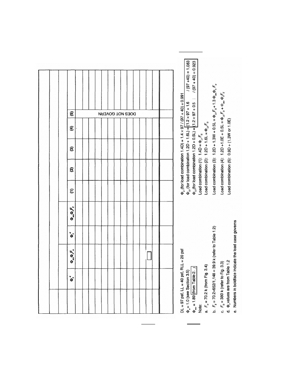
Showing below is an example of load coefficient calcu-
lations:
DL = 97 psf, LL = 40 psf, and RLL
= 20 psf (see Section 1.3)
φ
w
= 1.0 for typical truss T1B
= (36 + 12) / 2
× (1 / 36)
= 0.67 for truss T1D (see Fig. 1.4)
φ
L
for load combination of 1.2DL + 1.6RLL
= (1.2DL + 1.6RLL)/(full service gravity loads)
= (1.2
× 97 + 1.6 × 20) / (97 + 40)
= 1.083
φ
ecc
= 1.0 for typical truss T1B
= 380 / 335 = 1.13 for T1D
= 634 / 335 = 1.89 for T1F (see Table 2.4)
φ
h
= (see Table 1.2 for
φ
h
value of each story)
Load coefficients are calculated as follows:
D
i
= D
T
× φ
W
× φ
L
(3-1)
L
i
= L
T
× φ
W
× φ
L
(3-2)
W
i
= W
T
× φ
ecc
× φ
h
(3-3)
E
i
= E
T
× φ
ecc
× φ
h
(3-4)
Subscript i indicates the member being designed and
subscript T indicates the corresponding member of the orig-
inally calculated typical truss, i.e., truss T1B. D, L, W, E are
the dead, live, wind, and earthquake forces, and the load
coefficients are defined as follows:
φ
w
= Width or tributary area adjustment coefficient
φ
L
= Load adjustment coefficient for load factor com-
binations
φ
ecc
= Truss eccentricity coefficient
φ
h
= Story shear adjustment coefficient
The first two of the above coefficients are applied to
gravity loads, and the later two to lateral loads. Load coef-
ficient
φ
w
is applied to a truss whose bay length is different
from that of the typical truss. Load coefficient
φ
L
is the
ratio of a factored load combination to the full service grav-
Fig. 3.5 Computer analysis results of truss T1B due to gravity loads.
Fig. 3.6 Computer analysis results of truss T1B
of bottom floor due to lateral loads.

19
b. Wind
The maximum wind moment in the chords occurs in the
Vierendeel panel.
M = 86.87 ft-k (from Section 3.4 for typical truss
T1B)
φ
ecc
× M = 1.89 × 86.87 = 164 ft-k
M
u
= 164
× 1.3 = 213 ft-k
The axial force applied to the chord due to the wind load
can be neglected as will be explained in Section 3.8. The
above moment is also applied to the adjacent span, which
has a span length of 9.5 ft same as the span length used for
the gravity load moment calculation. The member forces of
the chords on the second story due to gravity and wind
loads are then combined as follows:
P
u
= 484 k
M
u
= 41 + 213 = 254 ft-k
It is observed that while wind loads vary with building
heights, gravity loads do not. Thus, Table 3.2 is created and
the chord moments are calculated using coefficient
φ
h
of
each story as shown. The designed wide-flange sections per
AISC Equation H1-1a are also shown in the table. To facil-
itate the design calculations, the axial force and bending
moment strengths of possible W10 members are calculated
first and listed in Table 3.3.
3.8 Computer Modeling
When designing staggered truss buildings using computer
models (stiffness matrix solutions), the results vary with the
assumptions made regarding the degree of composite action
between the trusses and the concrete floor. The design
results are particularly sensitive to modeling because a bare
truss is more flexible than a truss modeled with a concrete
floor. Upon grouting, the truss chords become composite
with the concrete floor and thus the floor shares with the
truss chords in load bearing. Yet, a concrete floor, particu-
larly a concrete plank floor, may not effectively transmit
tensile stresses. Also, there is limited information on plank
and steel composite behavior. In addition, lateral loads are
assumed to be distributed to the trusses by the concrete
floor diaphragm and the participation of the truss chords in
distributing these forces may be difficult to quantify.
A reasonable approach to this problem is the assumption
that the diaphragm is present when solving for lateral loads,
but is ignored when solving for gravity loads. This requires
working with two computer models—one for gravity loads
3.6 Vertical and Diagonal Members
The detailed calculations for the design of diagonal member
d1 in truss T1F of each floor using load coefficients are
shown in Table 3.1, where load coefficients
φ
L1
,
φ
L2
, and
φ
L3
are applied to different load combinations. Truss T1F
rather than typical truss T1B is intentionally selected as an
example here for explanation of how the load coefficients
are applied. Five load combinations as specified in ASCE
7 are considered in this table. A 50% live load reduction is
used in the design of the diagonal members. Numbers in
boldface in the table indicate the load case that governs.
The governing tensile axial forces of the diagonal members
range from 412 k to 523 k for different floors. HSS 10
×6×
½ is selected per AISC requirements for all the diagonal
members.
3.7 Truss Chords
The designer must investigate carefully all load cases so as
to determine which load case governs. For this design
example for truss chords, it is found that the load combina-
tion of 1.2D + 1.6W + 0.5L governs. The steel design must
comply with AISC Equation H1-1a.
P
u
/(
φ P
n
) + (8 / 9)
× [M
ux
/ (
φ
b
M
nx
)] [ 1.0 ]
where
φ = 0.90
Tension
= 0.85
Compression
φ
b
= 0.90
Bending
Calculations for gravity and wind loads are made sepa-
rately and then combined.
a. Gravity
It is assumed that the chords are loaded with a uniformly
distributed load. Using a 50% live load reduction, the fol-
lowing are calculated for the chords of truss T1F on the sec-
ond story:
φ
w
= 1.0 for truss T1F
M = 4.93
× 9.5
2
/ 10
= 44 ft-k (member end moments at joints)
P
= 525 k (from Fig. 3.3)
M
u
=
φ
L
M
= [(1.2
× 97 + 0.5 × 20) / (97 + 40)] × 44
= 41 ft-k
P
u
=
φ
L
P
= (1.2
× 97 + 0.5 × 20) / (97 + 40) × 525
= 484 k
WIND,
k
ip
s
Ta
bl
e 3
.1
Design
of
Diagonal
M
em
be
r d
1
of
T
ru
ss
T
1F
D
IA
G
O
N
A
L
MEMBER
d
1,
T
R
U
S
S
T
1F
SEISMIC,
k
ip
s
L
O
A
D
COMBINATIONS,
k
ip
s
Roof
12
11
10
9
8
7
6
5
4
3
2
Ground
9%
18
27
36
45
54
62
70
78
86
93
100%
F
in
d
1
o
f Typical
Truss
T1B
12
24
36
48
60
72
82
93
103
114
123
1
133
70.2
a
13%
26
39
51
61
70
78
85
91
95
98
100
10
20
29
38
46
53
59
64
69
72
74
75
75
39.9
b
377
377
377
377
377
377
377
377
377
377
377
377
377
380
c
412
e
412
412
412
412
412
412
412
412
412
412
412
412
366
382
397
413
428
444
458
471
485
499
511
352
523
361
370
380
389
397
404
410
415
419
422
425
426
426
Member
S
iz
es
H
S
S
10×6×1/2
H
S
S
10×6×1/2
H
S
S
10×6×1/2
H
S
S
10×6×1/2
H
S
S
10×6×1/2
H
S
S
10×6×1/2
H
S
S
10×6×1/2
H
S
S
10×6×1/2
H
S
S
10×6×1/2
H
S
S
10×6×1/2
H
S
S
10×6×1/2
H
S
S
10×6×1/2
H
S
S
10×6×1/2
Floor
20
Rev. 5/1/03
Revs.
5/1/03 - corrected parenthesis
Rev.
12/1/02
12/1/02 - deleted stray text
133
3
x
x
20)
20)
21
and the other for lateral loads, and then the results are com-
bined using load factors per code requirements. In combin-
ing the results, it is assumed that any axial load actions from
lateral loads are carried only in the concrete floor, but out-
of-diaphragm-plane shear and moment actions from lateral
loads are resisted by the steel chords.
3.9 Columns
The floor loads are delivered to the columns through the
truss-to-column connections. For trusses, the first diagonal
is responsible for carrying most of this load into the con-
nection. Thus, for a typical one-story truss, the first diago-
nal-to-column connection will carry the accumulated load
from two floors. For a truss with hangers or posts (Truss
type T2), the first diagonal-to-column connection will carry
the accumulated load from three floors.
A difficulty exists in evaluating the actions imposed on
the columns by the truss flexibility. The column design is
best done using the shear and moment applied to the
columns obtained from construction loads (plate loads) on
a bare truss. Column forces due to superimposed dead and
live loads and lateral loads are computed from a composite
truss.
Since columns support large tributary areas, the maxi-
mum live load reduction is permitted. For the purpose of
this example, 50% reduction is assumed. The load combi-
Table 3.2 Design of Staggered Truss Chords
TRUSS T1F
Floor
Φ
Φ
h
M
u,w
M
u
P
u
Section
AISC
Eq. H1-1a
Roof
9%
19
60
484
W10
×54
12
18
38
79
484
W10
×54
1.0
11
27
58
96
484
W10
×60
10
36
77
118
484
W10
×60
1.0
9
45
96
137
484
W10
×68
8
54
115
151
484
W10
×68
0.99
7
62
132
173
484
W10
×77
6
70
149
190
484
W10
×77
5
78
166
207
484
W10
×77
1.0
4
86
183
224
484
W10
×88
3
93
198
239
484
W10
×88
2
100
213
254
484
W10
×88
0.97
Ground
M
u
=
M
u,G
+
M
u,W
M
u,G
= Gravity load moment = 41 ft-k every story
M
u,W
= Wind load moment.
Table 3.3 Section Strengths for Chord Design,
F
y
= 50 ksi
Section
φφ
c
P
n
(k)
φφ
b
M
nx
(ft-k)
W10
×112
1400
551
W10
×100
1250
488
W10
×88
1100
424
W10
×77
961
366
W10
×68
850
320
W10
×60
748
280
W10
×54
672
250
W10
×49
612
226
W10
×45
565
206
W10
×39
489
176
W10
×33
413
146

22
nation of gravity loads, either 1.4D or 1.2D + 1.6L, governs
the column designs. The following shows the design of col-
umn 1F. Refer to Fig. 1.4 for the column location and Sec-
tion 1.3 for the dead and live loads used in the calculations.
Column Axial Force
Tributary Area = 72 / 2
× 64 / 2 = 1,152
DL
1
(plate loads only) = 80 psf
× 1,152 = 92.2 k
DL
2
(all dead loads except exterior walls)
= 97 psf
× 1,152 = 111.7 k
RLL = 20 psf
× 1,152 = 23 k
DL
2
+ RLL = 111.7 + 23 = 134.7 k
Two Floors:
DL
1
= 92.2
× 2 = 184 k
DL
2
+ RLL = 134.7
× 2 = 269 k
Exterior wall: 48 psf
× 36' × 9' = 16 k per story
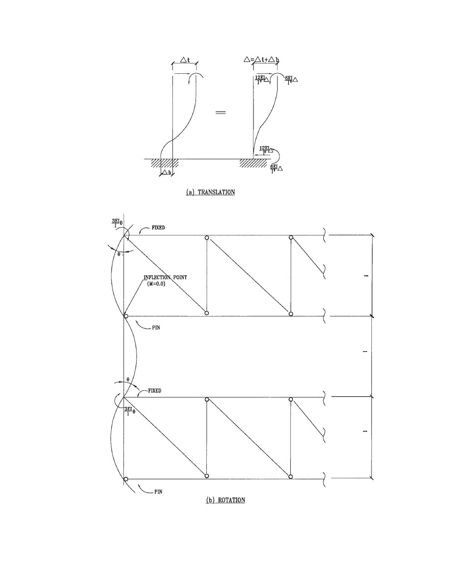
Column Bending
The truss axial deformation and downward deflection due
to gravity loads force the column-to-truss joints to translate
and rotate. It is assumed that the truss moment of inertia is
much larger than the columns. The assumed deformed
shape of the columns due to joint rotation is shown in Fig.
3.7(b). The member end moment caused by a unit rotation
is calculated as 3EI/A
c
for this deformed shape. The mem-
ber end moment caused by a unit translation is 6EI/A
c
2
as
indicated in Fig. 3.7(a). The moment of the column due to
gravity load is thus calculated as follows:
M
COL
= M
TRANS
+ M
ROT
M
TRANS
= 6EI (
∆
t
+
∆
b
) / A
c
2
M
ROT
=
−3EIθ / A
c
where
θ = 2∆
TS
/ L
∴ M
COL
=
where
∆
t
= Top chord axial deformation
=
Σ P
i
L
i
/ EA
i
∆
b
= Bottom chord axial deformation
=
Σ P
i
L
i
/ (EA
i
)
∆
TS
= Truss midspan deflection
L
= Truss span
A
c
= Column length
Example:
Only the dead loads of planks and structural steel are used
to calculate column moments. Superimposed dead and live
loads are applied after the erected planks act integrally with
the steel trusses. Additional column moments due to super-
imposed dead and live loads can be neglected because the
truss deformation caused by the superimposed loads is very
small as a result of the composite action of the truss and the
planks. However, these superimposed loads will increase
the column axial force.
∆
TS
= ¾ in. (assumed truss midspan deflection due to
weights of planks and structural steel)
L
= 64'
A
c
= 9'
For the top and bottom chords of W10
×54:
∆
t
=
Σ P
i
L
i
/ (EA
i
)
= [(9.5
× 12) / (29,000 × 15.8)]
× (268.6 + 443.6 + 525 + 525/2)
× [80/(97 + 40)]
= 0.218 in.
∆
b
= [(9.5
× 12) / (29,000 × 15.8)]
× (0 + 268.6 + 443.6 + 525/2)
× [80/(97 + 40)]
= 0.142 in.
The chord axial forces used in the above calculations are
from Fig. 3.3. Try W12
×65 for the column section.
M = [6
× 29000 × 174/( 9 × 12)]
× [(0.218 + 0.142)/(9 × 12)
− 0.75/(64 × 12)]
= 661 in-k
= 55 ft-k
where moment of inertia I
y
(rather than I
x
)is used because
the columns bend about the weak axis. The column
moment calculated above is for the top story. For other sto-
ries, the moments can be calculated similarly and the results
are shown in Table 3.4. It is noted that axial deformations
D
t
and D
b
are less in the bottom stories because of bigger
chord member sections. However, the column moments are
larger in the bottom stories because the column moment of
inertias, I
y
, are bigger in the bottom stories. These column
moments are then combined with the axial forces using load
factors for different load combinations. The results of the
load combinations and the column sections selected based
on the most severe load case are shown in Table 3.4. Col-
umn axial loads due to lateral loads, in this example, are
small and therefore, left out.
6
(
)
t
b
TS
c
c
EI
L
∆ + ∆
∆
−
A
A
23
Fig. 3.7 Column deformed shaped due to chord displacement.
24
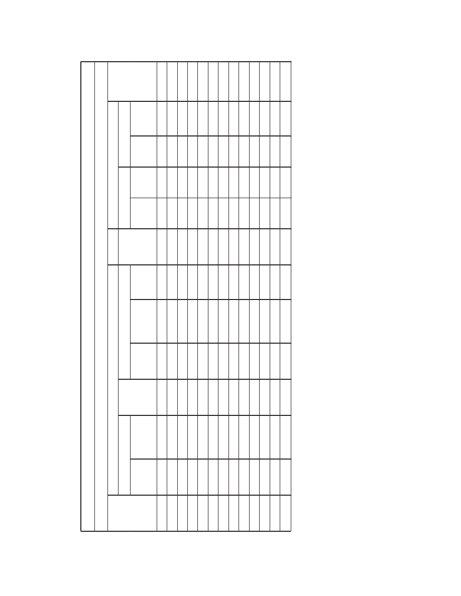
Table
3.4 D
e
sign
of C
o
lum
n
1F
COLUMN 1
F
Axial Forc
e
Mo
m
e
n
t
Load Comb
inatio
ns
Floor
Total
1.4 D
1.2 D
+
1.6 L
DL
1
(1)
DL
2
+ RLL
(2)
Exterior
Wall
(3)
DL
1
(
4)
DL
2
+ RLL
(5)
Exterior
Wall (6)
DL
1
(7)
P
u
(8)
M
u
(9)
P
u
(10)
M
u
(11)
Section
Roof
184
269
16
184
269
16
55
258
77
360
66
W12
×
65
12
16
184
269
32
258
380
W12
×
65
11
184
269
16
368
538
48
65
515
91
740
78
W12
×
87
10
16
368
538
64
515
759
W12
×
87
9
184
269
16
552
807
80
77
773
108
1120
92
W12
×
12
0
8
16
552
807
96
773
1139
W12
×
12
0
7
184
269
16
736
10
76
112
82
1030
115
1499
98
W12
×
15
2
6
16
736
1076
128
1030
1518
W12
×
15
2
5
184
269
16
920
1345
144
97
1288
136
1879
116
W12
×
19
0
4
16
920
1345
160
1288
1898
W12
×
19
0
3
184
269
16
1104
1614
176
105
1546
147
2258
126
W12
×
23
0
2
16
110
4
1614
192
1546
2278
W12
×
23
0
G
round
184 k
269 k
16 k
1288 k
1883 k
208 k
55 ft
-k
Note: 1.
DL
1
i
n
c
lude
s t
he w
e
ig
hts o
f pre
c
a
s
t p
lan
ks
and
stru
c
tural
ste
e
l o
n
ly
.
2. DL
2
in
clu
d
e
s
al
l th
e d
ead l
oad
s e
x
c
ept t
h
e
w
e
ight
of
exter
ior w
a
lls.
3. A
ll th
e c
o
lum
n
s be
nd
about
the
w
eak
ax
is (
s
e
e
Fig
.
1.4).
4. T
he m
o
m
ent
s s
how
n
in th
e ta
ble
are
cau
s
ed
by
the
w
e
ight
s of
pre
c
a
s
t pl
an
k an
d
struc
tura
l st
eel
onl
y.
5. Co
lum
n
(8)
=
1.
4
×
C
o
lum
n
(4);
Col
u
m
n
(9) =
1.4
×
Colum
n
(7).
6. Co
lum
n
(1
0) = (1
.2
×
97 + 1
.6
×
2
0
) / (9
7 + 2
0
)
×
Co
lum
n
(5) +
1.2
×
C
o
lum
n
(6)
;
C
o
lum
n
(11)
= 1.
2
×
Co
lu
mn
(
7
).
25
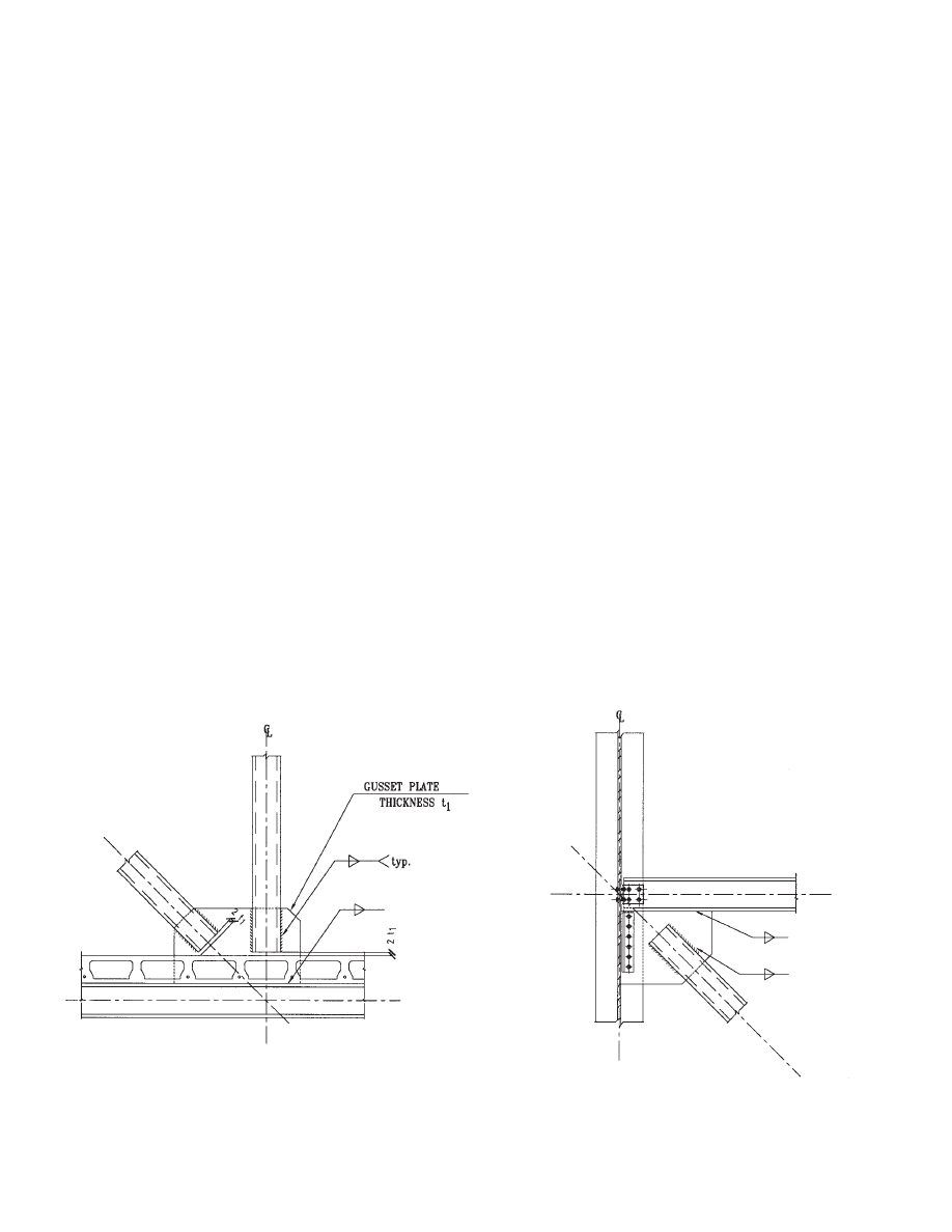
4.1 General Information
The typical connection of web members to truss chords
consists of welded gusset plates. Since the truss is shop fab-
ricated and transported in one piece, all connections are
shop welded (see Fig. 4.1). Only truss-to-column connec-
tions are bolted in the field (Fig. 4.2) when the truss is
erected.
The HSS web member connection to the gusset plate is
often made by cutting a slot in the middle of the HSS sec-
tion. The design methodology that follows is based upon
the recommendations listed in the AISC Hollow Structural
Sections Connections Manual (AISC, 1997). Shown in Fig.
4.1 is a typical slotted HSS to gusset plate connection. Seis-
mic behavior and design of gusset plates was studied by
Astaneh-Asl (1998), and will be discussed in Chapter 5.
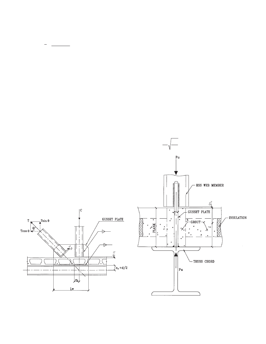
4.2 Connection Between Web Member and Gusset Plate
First, consider an HSS web member in tension. The design
strength of the connection between the HSS and the gusset
plate is the smallest value among the following four limit
state considerations.
1. Shear Lag Fracture Strength in the HSS
φR
n
=
φF
u
A
e
φ = 0.75
2. Shear Strength of the HSS at Welds
φR
n
=
φV
n
=
φ (0.6 F
y
)(4L
w
t)
φ = 0.9
3. Strength of the Weld Connecting the Gusset Plate to
the HSS
φR
n
=
φF
w
A
w
φ = 0.75
4. Shear Strength of the Gusset Plate
φR
n
=
φV
n
=
φ (0.6F
y1
)(2L
w
t
1
)
φ = 0.9
The notations used in the above four limit state strength
expressions are as follows:
F
u
= specified minimum tensile strength of the
HSS, ksi
F
y
= specified minimum yield stress of the HSS, ksi
A
e
= effective net area of the HSS, in
2
= UA
n
A
n
= A
g
− 2 t t
1
A
g
= gross area of the HSS, in
2
Chapter 4
CONNECTIONS IN STAGGERED TRUSSES
Fig. 4.1 Slotted HSS and gusset plate connection.
Fig. 4.2 Truss to column connection.
26
U
= 1
− ( / L
w
)
≤ 0.9
=
L
w
= length of the weld to HSS, in
≥ 1.0 H (As a rule of thumb, L
w
should not be
less than the HSS depth)
4L
w
= total weld length
B
= width of the HSS section, in
H
= depth of HSS section, in
t
= HSS wall thickness, in
t
1
= gusset plate thickness, in
F
w
= nominal weld strength, ksi
= 0.60 F
EXX
(1.0 + 0.5 sin
1.5
θ)
F
EXX
= electrode classification number, i.e., minimum
specified strength, ksi
θ
= angle of loading measured from the weld lon-
gitudinal axis
A
w
= effective area of weld throat, in
2
= 0.707 W
e
(4 L
w
)
W
e
= effective weld size, in
= W
w
− 1/16”
W
w
= weld size, in
F
y1
= specified minimum yield stress of the gusset
plate, ksi
In case the HSS web member is in compression, in addi-
tion to the limit states (2), (3), and (4) stated above, the fol-
lowing limit state has to be considered as well.
5. Strength Based on Buckling of the Gusset Plate
The provided compression strength is calculated based
on simple column buckling procedures. The procedure
assumes that both ends of the gusset plate are fixed and can
sway laterally (See Fig. 4.3 and 4.4).
φ
c
P
n
=
φ
c
A
g
F
cr
where
φ
c
= 0.85
P
n
= nominal compressive strength, kips
A
g
= gross area of gusset plate, in
2
. Whitmore’s 30-
degree effective width area (Whitmore, 1952;
Astaneh-Asl, Goel, and Hanson, 1981) should
be used for a large gusset plate.
F
cr
= critical compressive stress, ksi
=
=
λ
c
= slenderness parameter
=
2
1
0.658
c
y
F
λ
for
λ
c
≤ 1.5
for
λ
c
> 1.5
2
1
(0.877 /
)
c
y
F
λ
1
y
F
k
r
E
π
A
Fig. 4.3 Forces to be considered at the
weld connecting gusset plate and chord.
Fig. 4.4 Gusset plate in compression.
for rectangular HSS
2
2
4(
)
B
BH
x
B
H
+
=
+
x
⎯
x
⎯

27
F
y1
= specified minimum yield stress of the gusset
plate, ksi
E
= modulus of elasticity, ksi
k
= effective length factor = 1.2
A
= laterally unbraced length of plates, in
r
= governing radius of gyration, in
= t
1
/
t
1
= gusset plate thickness, in
4.3 Connection Between Gusset Plate and Chord
The stress distribution in the weld connecting the gusset
plate and the chord is much more complex. As shown in
Fig. 4.3, the weld is subject to shear force V = T cos
θ, ten-
sile force P = T sin
θ − C, and moment
M
= T cos
θ × e
v
− P × e
h
= T cos
θ × d / 2 − (T sin θ − C) × e
h
If no vertical external load is applied at the joint, tensile
force P = T sin
θ − C is zero. While shear force V causes
shear stress in the weld, tensile force P and moment M
induce tensile or compressive normal stress. These stresses
must be combined vectorially. In design, a unit throat thick-
ness of the weld is usually assumed in the stress calcula-
tions. The maximum stress caused by the combination of
factored V, P, and M must be equal to or less than the
strength of the weld. The provided design strength of a unit
length of weld is
φR
n
=
φF
w
A
w
=
φ(0.6 F
EXX
)(0.707 W
w
)
where
φ = 0.75. Meanwhile, the maximum shear stress
caused by the direct shear must be less than the shear
strength of the gusset plate. The provided design shear
strength of the gusset plate per unit length along the weld
connection is given by
φR
n
=
φV
n
=
φ(0.6F
y1
) t
1
where
φ = 0.9
4.4 Design Example
The connection design of diagonal member d1 in Truss T1F
to the chord of the second story is calculated in this exam-
ple.
Diagonal member d1: HSS 10
× 6 × ½
P
u
= 523 k (in tension, see Table 3.1)
Connection between the HSS and the gusset plate:
1. Shear Lag Fracture Strength in the HSS
φR
n
=
φF
u
A
e
A
n
= A
g
− 2 t t
1
= 13.5
− 2 × 0.465 × ½
= 13.04 in
2
L
w
= 20 in
= (6 + 2
× 6 × 10) / 4 (6 +10)
= 2.44 in
U
= 1
− 2.44 / 20 = 0.88 < 0.9
φR
n
= 0.75
× 62 × 0.88 × 13.04
= 534 k
2. Shear Strength of the HSS at Welds
φR
n
=
φ (0.6F
y
)(4 L
w
t)
= 0.9
× 0.6 × 46 × 4 × 20 × 0.465
= 924 k
3. Strength of the Weld Connecting the Gusset Plate to
the HSS
φR
n
=
φF
w
A
w
θ
= 0
° (the load direction is parallel to the weld
direction)
F
EXX
= 70 ksi
F
w
= 0.6
× 70 × (1.0 + 0) = 42 ksi
A
w
= 0.707
× (3/8 − 1/16) 4 × 20
= 17.68 in
2
φR
n
= 0.75
× 42 × 17.68
= 557 k
4. Shear Strength of the Gusset Plate
φR
n
=
φ(0.6 F
y1
)(2 L
w
t
1
)
= 0.9
× 0.6 × 50 × 2 × 20 × ½
= 540 k
The smallest value among the four cases above governs,
i.e.,
φR
n
= 534 k, which is larger than P
u
= 523 k.
Calculations also must be made for the connection
between the gusset plate and the chord to ensure its strength
is adequate.
4.5 Miscellaneous Considerations
Reinforcement of trusses can be accomplished using field
welded plates and channels (see Figs. 4.5 and 4.6). It is
advised to leave the chord web free of stiffeners, plates,
etc., so as to allow future sistering of channels to be fitted
in the web.
12
x
⎯
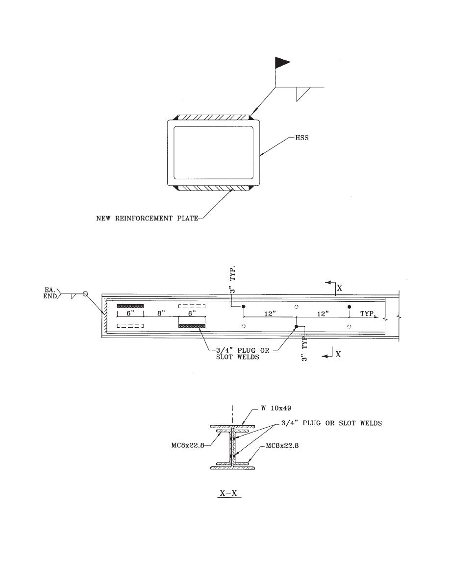
28
Fig. 4.5 Truss HSS reinforcement detail.
Fig. 4.6 Truss chord reinforcement detail.

29
5.1 Strength and Ductility Design Requirements
The staggered truss system provides excellent lateral resist-
ance in the transverse direction of the building (the direc-
tion of the trusses). A separate lateral-force-resisting system
must be provided in the longitudinal direction of the build-
ing. This longitudinal lateral-force-resisting system usually
consists of perimeter moment frames on the exterior of the
building or bracing systems organized around the building
elevator cores and stair towers.
In designing a staggered-truss system for seismic forces,
several questions related to the system behavior must be
addressed. Of primary importance is the selection of an
appropriate seismic response modification factor R to be
used in developing the base shear of the building in the
staggered truss direction. Prior research both in the United
States and Japan has indicated that the staggered-truss sys-
tem behaves as a combination of a braced system and a duc-
tile moment resisting system under the action of seismic
excitation. Hanson and Berg (1973) have shown that with
proper detailing, the Vierendeel panel in the center of the
truss can provide significant ductility in the structural
response. The presence of braces in the other panels con-
centrates the energy dissipation to the Vierendeel panel. In
order to ensure that this is the primary source of energy dis-
sipation, the bracing diagonals and their connections should
be designed to remain nominally elastic under the assumed
seismic forces. Equal care must be taken in the design of the
diaphragm system, which is an integral part of the resisting
system to transfer lateral forces. It is essential to design the
diaphragm to keep the in-plane stresses below yield limits.
In regions of high-seismic activity (that is, when it is
desirable or required to provide a system with an R factor
greater than 3), researchers suggest that the behavior of the
staggered-truss system be evaluated utilizing time history
analysis enveloped with a spectrum for the site under con-
sideration. The ductility demands on the chords can then be
evaluated directly from the analysis. The response charac-
teristics of a staggered-truss structure that dissipates energy
mainly through Vierendeel panels are similar to a ductile
moment frame or an eccentrically braced frame. This would
imply that an R factor of 7 or 8 could be used for the design
in the transverse direction of the building.
In regions of moderate seismic activity, using a response
modification factor equivalent to that used for ordinary
moment frames (R = 4.5) would be appropriate (Hanson
and Berg, 1973). However, given the limited data available,
the designer may select a more conservative value of R = 3
for the overall behavior. When R is taken as 3, special seis-
mic detailing is not required. In selecting an appropriate
natural period of the building to be used in calculating the
base shear, it is recommended that the classification of the
structure type be assigned on the basis of the way the seis-
mic energy is dissipated. The presence of the braces in the
truss system does not influence the ductility of the system
since these elements and their connections are designed to
avoid yielding under a seismic event.
5.2 New Seismic Design Provisions for Precast
Concrete Diaphragms
According to Ghosh (1999) and Hawkins and Ghosh
(2000), the Uniform Building Code has required that in
regions of high seismicity (zones 3 and 4—i.e., when R is
taken greater than 3) cast-in-place topping slabs over pre-
cast planks must be designed to act as the diaphragm, with-
out relying on the precast elements. The design philosophy
is that a topping slab acts in the same manner as a cast-in-
place reinforced concrete slab under in-plane lateral loads.
The Northridge earthquake showed that this is not the case.
In some cases the topping cracked along the edges of the
precast elements and the welded wire fabric fractured.
Accordingly, the diaphragms may have become the equiva-
lent of untopped diaphragms with the connections between
the planks, the chords, and the collectors not detailed for
that condition.
Unlike topped diaphragms, untopped hollow-core plank
diaphragms with grouted joints and chords have performed
satisfactorily in earthquakes and in laboratory tests. Thus,
according to Ghosh (2000), when diaphragms are designed
using appropriate forces to ensure continuity of load path,
force development across joints, deformation compatibility,
and connections of adequate strength, they may perform
well even untopped.
5.3 Ductility of Truss Members
Staggered trusses normally use rectangular HSS, which act
mostly as concentrically braced frames (CBF). CBF’s are
characterized by a high elastic stiffness, which is accom-
plished by the diagonal braces that resist lateral forces by
developing internal axial actions. Only the chords, which
span across Vierendeel panels at corridors and openings
provide some flexibility and energy dissipation capacity by
developing out-of-plane flexural and shear actions.
For braced frames, tension-only systems are not consid-
ered to provide a sufficient level of energy dissipation capa-
bility. They are assigned a small response modification
Chapter 5
SEISMIC DESIGN

30
factor R, and are designed for larger forces than the nomi-
nal design force to account for impact. Compression braces,
however, are susceptible to fracture failure induced by local
buckling and subsequent material failure, unless stringent
seismic slenderness ratios are provided. Local buckling in
HSS reduces the plastic moment resistance and conse-
quently the axial compressive strength. Furthermore, the
degree and extent of the local buckling at the plastic hinge
has a major influence on the fracture life of the brace. Pre-
venting severe local bucking is the key to precluding pre-
mature material fracture. The onset of local bucking can be
delayed until significantly into the inelastic range by reduc-
ing the width-to-thickness ratio b/t of the brace. In high-
seismic applications, from the AISC Seismic Provisions,
the b/t ratio for HSS should be limited to 110/ .
The exact contribution of Vierendeel panels to energy
dissipation in staggered trusses has not been documented.
Subsequently, new resources for research on this topic are
necessary.
Black (1980) suggested that the most efficient braces are
tubular cross-sections with small kA / r. He also suggested
that improved performance can be achieved by reducing the
b/t ratios of the rectangular brace HSS. Black ranked the
tested cross-sections in the following descending order of
effectiveness for a given slenderness ratio:
1. Round HSS brace
2. Rectangular HSS brace
3. I-shaped brace
4. T-shaped brace
5. Double-angle brace
Black recommended that built-up members not be used
as braces for applications in which severe cyclic loading is
anticipated unless the members making up the built-up sec-
tion were adequately stitched together.
5.4 Seismic Design of Gusset Plates
During an earthquake excitation, the gusset plates connect-
ing bracing members should have sufficient ductility to
deform and provide the end rotation demands of the mem-
bers. To avoid brittle behavior of the structure, the gusset
plate connections should be governed by a yielding failure
mode rather than a fracture mode. This can be achieved by
designing the failure modes in a hierarchical order in which
the ductile failure modes such as yielding occur prior to the
brittle failure modes such as fracture.
Bracing members and sometimes gusset plates are the
most active elements during an earthquake. Four zones can
be identified in a bracing system: bracing member, connec-
tion of the bracing member to the gusset plate, gusset plate,
and connection of the gusset plate to the chord. Each of the
above four zones has its own failure modes, and the gov-
erning failure mode within each of the zones should be duc-
tile. In order to increase the global ductility of the braced
frame, the occurrence of the yielding in the four zones
should be in the following order: yielding of bracing mem-
ber, yielding of gusset plate, and yielding of connection ele-
ments such as welds. Yielding of bracing member results in
large axial plastic deformations, which in turn results in
large ductility of the braced frame. On the other hand,
yielding of relatively short welds cannot provide large
global ductility.
The emphasis of this section is on the seismic design of
gusset plates. Failure modes of a typical gusset plate in the
order of ductility desirability are as follows (Astaneh-Asl,
1998):
1. Yielding of Whitmore’s area of gusset plate
This is most desirable failure mode of a gusset plate. Yield-
ing caused by direct tension or compression can occur in the
Whitmore effective width area (Whitmore, 1952; Astaneh-
Asl, Goel, and Hanson, 1982). The yield strength of the
failure mode is
P
y
= A
gw
F
y
where A
gw
= gross area of gusset plate as per Whitmore’s
30-degree lines and F
y
= specified minimum yield stress of
the gusset plate.
2. Yielding of critical sections of gusset plate under
combined stresses
Critical sections of gusset plates can yield under a combi-
nation of axial load, bending, and shear. To determine
strength of gusset plate subject to combined loads, the fol-
lowing interaction equation is suggested:
where N, M, and V are the axial force, bending moment, and
shear force on the critical section;
φN
y
,
φM
p
, and
φV
y
are the
axial load strength in yielding, plastic moment strength, and
strength in shear yielding, respectively.
3. Buckling of gusset plate
Whitmore's effective width area can be used to establish
buckling strength of a gusset plate subject to direct com-
pression:
P
y
= A
gw
F
y
y
F
2
1.0
y
p
y
N
M
V
N
M
V
⎛
⎞
⎛
⎞
+
+
≤
⎜
⎟
⎜
⎟
φ
φ
φ
⎝
⎠
⎝
⎠
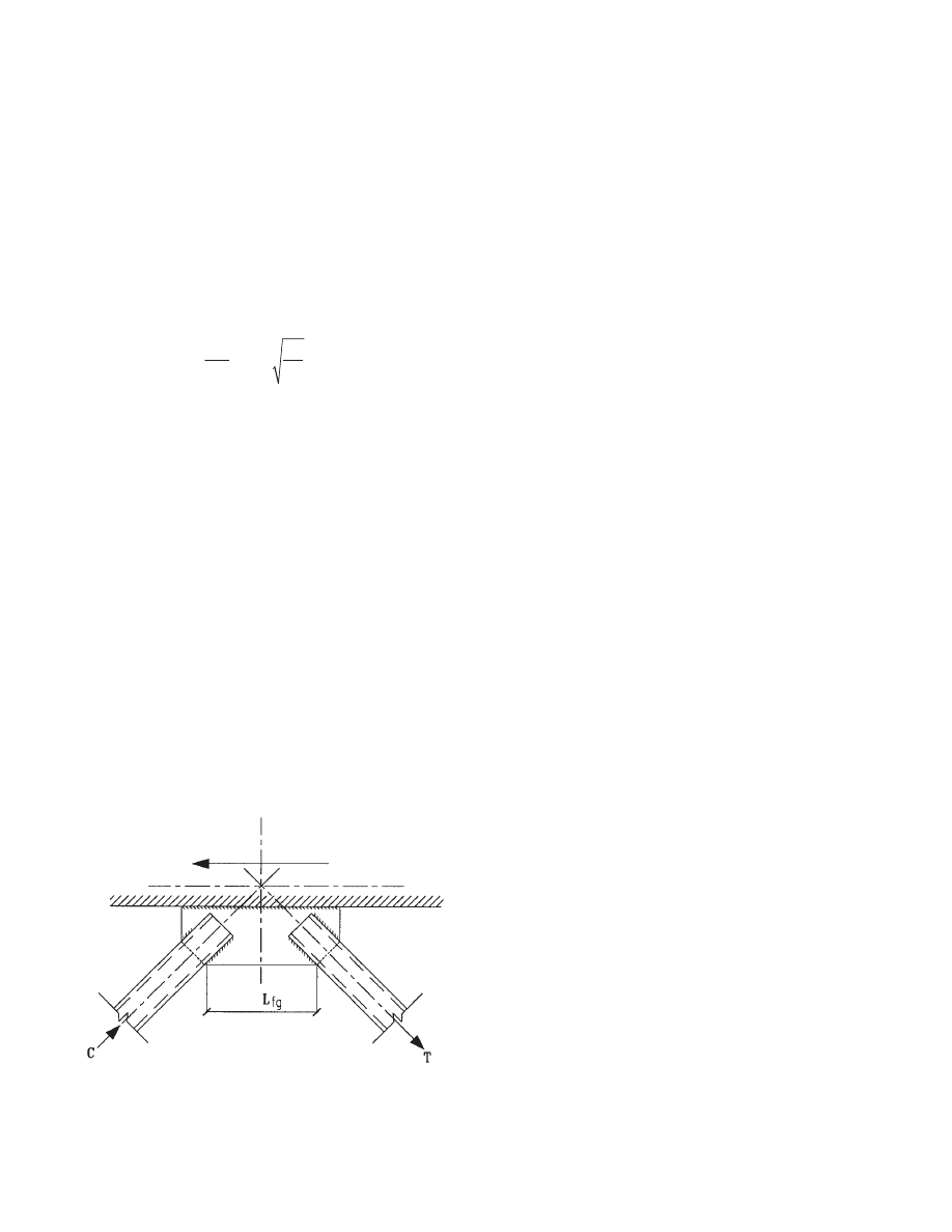
31
where F
cr
is the cirtical stress acting on a 1-in.-wide strip
within the Whitmore effective width. The effective length
factor K is suggested to be taken as 1.2 because of a possi-
bility of end of bracing member moving out of plane.
4. Buckling of edges of gusset plate
A gusset plate may buckle along its free edge as shown in
Fig. 5.1. The edge buckling limits the cyclic ductility of the
gusset plate. To prevent edge buckling under severe cyclic
loading, the following equation is proposed by Astaneh-Asl
(1998):
where L
fg
, t
1
, and E are free edge length, thickness, and
modulus of elasticity of the gusset plate, respectively.
5. Block shear failure
Block shear failure is a relatively less ductile failure mode
and undesirable. To ensure that the strength of gusset plate
in block shear failure is greater than its strength in yielding,
the following criterion is suggested:
φ
n
P
bs
≥ φ(1.1R
y
P
y
)
where R
y
is the ratio of expected yield strength to specified
yield strength. The values of R
y
are given in AISC Seismic
Provisions for Structural Steel Buildings (1997). P
bs
is the
nominal strength of gusset plate in block shear failure,
which can be calculated using the equations:
P
bs
= 0.6R
y
F
y
A
gv
+ F
u
A
nt
for F
u
A
nt
≥ 0.6F
u
A
nv
P
bs
= 0.6F
u
A
nv
+ R
y
F
y
A
gt
for F
u
A
nt
< 0.6F
u
A
nv
where A
gv
and A
nv
are the gross and net areas subject to
shear, and A
gt
and A
nt
are the gross and net areas subject to
tension, respectively. F
u
is the specified minimum tensile
strength.
6. Fracture of net area of gusset plate
To ensure that this relatively brittle failure mode does not
occur prior to yielding of gusset plate, the following crite-
rion is suggested:
φ
n
P
n
≥ φ(1.1R
y
P
y
)
where P
n
= A
nw
F
u
. A
nw
is the net area of gusset plate along
the Whitmore section.
5.5 New Developments in Gusset Plate to HSS Connections
Cheng and Kulak (2000) have determined on the basis of
tests that the slotted end of the HSS is stiffened significantly
as the result of the constraint provided by the gusset plate.
In most of the physical tests, the geometries provided
allowed yielding to occur in the gross section of the HSS
without fracture in the net section of the connection region.
However, use of a short weld length or the absence of trans-
verse welds across the thickness of the gusset plate weld
may increase the stress concentration sufficiently that frac-
ture will take place where the HSS enters the gusset plate.
In such a case, ductility will be reduced. Nevertheless, in all
the configurations investigated by them, the slotted HSS
exhibited considerable ductility, regardless of the location
of fracture.
Based on tests and numerical analysis performed by
them, it was concluded that shear lag does not significantly
affect the ultimate strength of slotted tubular sections that
are welded to gusset plates. The shear lag expression given
in Section 2.1(b) of the AISC Specification for the Design
of Steel Hollow Structural Sections underestimates the
strength of a slotted tube-to-gusset plate connection. Never-
theless, a transverse weld can be used across the thickness
of the gusset plate since it increases the ductility of the slot-
ted member significantly without incurring much extra cost.
See Cheng and Kulak (2000) for further information.
Fig. 5.1 Edge buckling of gusset plate.
1
0.75
fg
y
L
E
t
F
≤

32
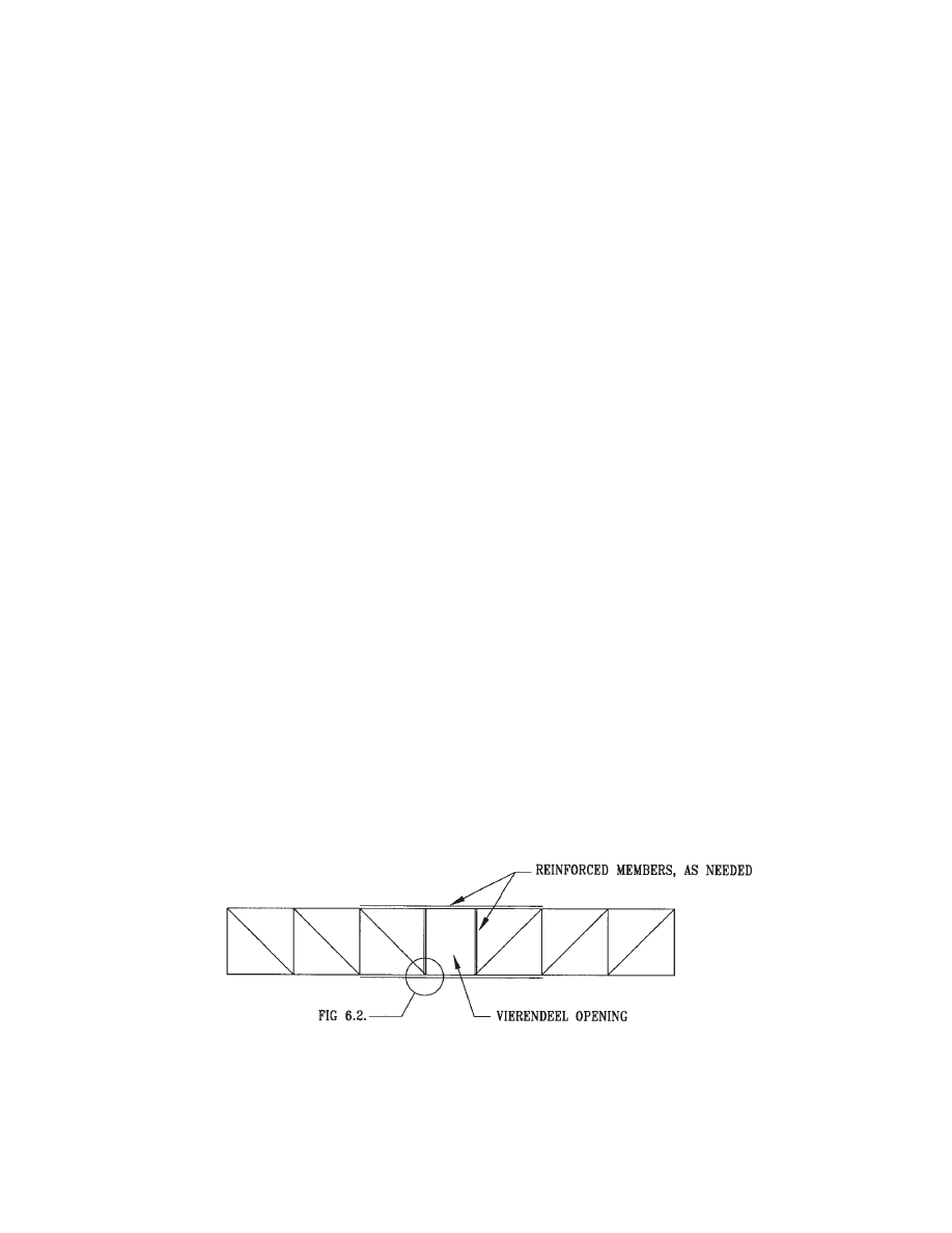
33
6.1 Openings
Where openings in the truss are needed for room access,
Vierendeel panels can be designed in the truss geometry
(Fig. 6.1). The effect of such a panel is one of shear trans-
fer across the opening through bending in the chords, which
increases the flexibility of the truss and the bending
moments in the chords to both vertical and lateral loads.
Larger members and rigid connections, at a premium,
reduce this flexibility, but do not eliminate it. The problem
can be solved by approximate methods or by using a com-
puter program. The latter method is recommended for all
special framing conditions. Connections for members fram-
ing a Vierendeel panel are shown in Figs. 6.1 and 6.2.
6.2 Mechanical Design Considerations
Vertical chases are needed for distribution of plumbing
pipes and ducts. When needed, they should be sized and
located to eliminate the need for stagger. Staggering results
in a cost increase. The common solution is to increase the
chase size and to locate it midway between the truss mod-
ules.
6.3 Plank Leveling
Precast plank is delivered to the site with camber. Fabrica-
tion variances may result in adjacent planks having differ-
ential camber.
Differential plank camber is best removed mechanically
prior to grouting. This is accomplished by inserting
threaded rods with lock plates and nuts in the joints and
then forcing the planks together mechanically by turning
the nuts. Grouting takes place after the planks are aligned.
Another way to create level floors is by using a leveling
compound such as gypcrete.
6.4 Erection Considerations
Staggered trusses are fabricated in the shop and delivered to
the site, generally in one piece. Erecting staggered trusses in
busy downtown areas (such as New York City) does not
present a special challenge. The usual steel tolerances,
which are listed in the AISC Code of Standard Practice, are
normally adequate for erection purposes, even for busy
downtown locations.
For practical reasons, staggered truss buildings are at
least six stories in height and generally at most 25 stories in
height. Higher buildings are possible when the staggered
trusses are supplemented with special wind and/or seismic
frames and reinforced diaphragm floors. The reason for the
height limit is the staked geometry at the roof and second
floor, which is by necessity, discontinuous.
Economy is further achieved by lumping member sizes
into a few groups. This will usually result in an increase in
steel weight, but a reduced overall cost due to the associated
savings in labor. Also, HSS sizes are used for vertical and
diagonal members with those member properties listed in
AISC Hollow Structural Sections Connections Manual
(AISC, 1997).
Economy may also be achieved by using longer columns
with fewer splices. Up to four stories tall columns have
been used with no difficulty. The faster erection and
reduced field labor more than compensates for the cost of
the added material.
Structural stability is mandatory during erection. Tempo-
rary steel braces or tension cables are recommended. Plank
Chapter 6
SPECIAL TOPICS
Fig. 6.1 Opening in truss using Vierendeel panel.
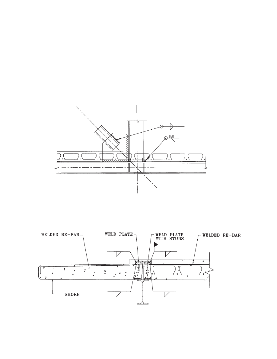
34
weld plates can also be used. The plank weight may provide
bracing through friction at the interface with the truss
chords. However, with friction alone, erection tolerances
such as column plumbing may be jeopardized.
6.5 Coordination of Subcontractors
During construction, the steel and plank shop drawings may
require special coordination. The plank manufacturer
locates plank embedded items such as weld plates. The steel
fabricator locates steel stiffeners, or wedges, shims, etc. A
meeting between the steel and plank contractors is advis-
able to agree on dimensions. Such a meeting is best coordi-
nated by the general contractor prior to the start of fabrica-
tion.
6.6 Foundation Overturning and Sliding
At foundation level, the codes require adequate safety fac-
tors against sliding and overturning. The safety factors vary
with the building codes, but are usually 1.5. Sliding resist-
ance is provided by friction of the footings and the base-
ment slab against the soil, active pressure against the
foundation walls, grade beams and footings, battered piles,
Fig. 6.2 Details at Vierendeel openings.
Fig. 6.3 Precast cantilever balcony.

35
etc. The engineer of record prepares calculations and pro-
vides the details required to ensure sliding and overturning
safety.
Overturning with staggered trusses is usually not a con-
cern for mid-rise buildings.
6.7 Special Conditions of Symmetry
The typical staggered truss is symmetrical about its center-
line. Symmetry of geometry and symmetry of loads result
in reduced member sizes. Non-symmetry results in
increased sizes—most affected are the chords, which sup-
port out-of-plane actions. Such non-symmetry occurs at ele-
vator machine rooms, at roof appurtances, at public spaces
on private floors and at large guest suites with access doors.
Pattern live loads often create non-symmetry. Pattern
loadings are created by skipping the loads on alternate bays.
With staggered trusses, if load patterns are created by skip-
ping alternate bays, symmetry still remains. However, skip-
ping loads in alternate rooms on the same side of the truss
creates non-symmetry.
Future changes in truss geometry or loading is possible.
Often, such modifications entail removal of diagonals and
reinforcing of the chords. Chord reinforcement is accom-
plished with steel plates or with channels fitted within the
web.
6.8 Balconies
Precast plank balconies are best manufactured using solid
slabs. Since hollow cores entrap moisture, solid slabs are
best used for durability. Fig. 6.3 shows a method of attach-
ment of balconies.
6.9 Spandrel Beams
Spandrel beams support the exterior walls. Where precast
concrete planks are perpendicular to spandrel beams, the
spandrels support floor loads as well. The spandrel beams
in the other direction support no floor loads. In addition, on
the wide face of the building, the spandrels are an integral
part of the moment frame for resisting wind and seismic
loads. The design considerations for such frames are not
within the scope of this design guide. The exterior wall is
often eccentric with respect to spandrel beams and columns.
A field weld between the plank and the beam flange
strengthens the beam torsionally and enhances its ability to
span between columns (see Fig. 2.6).

36

37
Fire safety is a fundamental requirement of building design
and construction and fire resistance is one of the most vital
elements of all components of a structure.
Qualifying criteria to meet these requirements are
included in various building codes of national stature.
These are used as standards in different areas of the country
and which may or may not be further regulated by the local
authorities having jurisdiction. The codes (and publishing
organization) are:
- Standard Building Code (SBCCI)
- Uniform Building Code (ICBO)
- National Building Code (BOCA)
These code regulations are based on performance
achieved through the standard ASTM E119 test (Alternative
Test of Protection for Structural Steel Columns). Due to the
dimensional constraints imposed by the fire testing cham-
bers, specific fire tests for steel trusses that simulate actual
conditions have not been performed. Therefore, individual
truss members are regarded as columns for the purpose of
rating their fire resistance and the applicable code require-
ment will be applied for each member.
By definition, a staggered truss spans from floor slab to
floor slab. Slabs are typically pre-cast concrete and have a
fire resistance rating. The truss and columns are other ele-
ments of this assembly requiring fire protection. There are
basically two methods of providing fire protection for steel
trusses in this type of assembly:
• Encapsulating it, in its entirety, with a fire-rated enclo-
sure.
• Providing fire protection to each truss member.
In the former, enclosure can be any type of fire-rated
assembly. Local regulation, however, might reference dif-
ferent testing laboratories as accepted standards for a par-
ticular fire rating.
For economy in materials and construction time, gypsum
board and metal stud walls are preferred. Gypsum board
type “X” and light-gage metal studs in any of the approved
configurations for a particular rating is acceptable. How-
ever, removals of portions of the wall, renovations or addi-
tions with non-rated assemblies are issues that need to be
considered to avoid possible future violations of fire rating
integrity when choosing this method.
The other option is to protect each truss member with one
of the following methods:
• If the truss is to be enclosed and/or protected against
damage and without regard to aesthetics, gypsum-
based, cementitious spray-applied fireproofing is
often the most economical option.
• Intumescent paint films can be used where aesthetics
are of prime concern, and visual exposure of the steel
truss design is desired. In addition this product is suit-
able for interior and exterior applications. Neverthe-
less, this method is often one of the most expensive at
the present time.
• For exterior applications and for areas exposed to traf-
fic, abrasion and impact, a medium- or high-density
cement-based formulation is suitable and can be
trowel-finished for improved aesthetics.
Whatever method is chosen, the designer must work in
close consultation with the product manufacturer by sharing
the specifics of the project and relating the incoming tech-
nical information to the final design. Final approval must be
obtained from the local authorities having jurisdiction over
these regulations.
Chapter 7
FIRE PROTECTION OF STAGGERED TRUSSES

38

39
Astaneh-Asl, Abolhassan, Seismic Behavior and Design of
Gusset Plates, Report of Department of Civil and Envi-
ronmental Engineering, University of California, Berke-
ley, 1998.
Astaneh-Asl, Abohlassan, Goel, S. C., and Hanson, R. D.,
Cyclic Behavior of Double Angle Bracing Members with
End Gusset Plates, Report No. UMEE 82R7, University
of Michigan, Ann Arbor, 1982.
Berg, G. and Hansen, R.P., A Seismic Design of Staggered
Truss Buildings, ASCE-1973.Brazil, Aine, P.E., “Stag-
gered Truss System Proves Economical For Hotels”,
Modern Steel Construction Report, September 2000, pp
34-39.
Bruneau, Michael, Chia-Ming Uang and Whittaker,
Andrew, Ductile Design of Steel Structures, New York,
McGraw-Hill, 1998.
Cheng, Roger and Kulak, Geoffrey L., “Gusset Plate Con-
nection to Round HSS Tension Members”, Engineering
Journal, AISC., Vol. 37, No. 4., December 2000, p.133.
Cohen, P.M., “Design Solutions with Staggered Truss Sys-
tem”, Modern Steel Construction News, 1986, pp 5-12.
Dudek, Paul H., A Staggered Truss High-Rise Housing Sys-
tem, New York: The Ronaid Press Company, 1960.
Ghosh, S. K., “Changes Under Development in Seismic and
Structural Code Provisions”, PCI Journal, V44, N6,
November/December 1999, p. 96.
Hawkins, Neil and Ghosh, S. K., “Proposed Revisions to
1997 NEHRP Recommended Provisions for Seismic
Regulations for Precast Concrete Structures Part 3-
Diaphragms”, PCI Journal, V45, N6, November/Decem-
ber 2000, pp. 50-58.
Hibbeler, Russell, Structural Analysis, Prentice Hall, 1998.
High-Rise Housing in Steel, the Staggered Truss System,
Massachusetts Institute of Technology, Departments of
Architecture and Civil Engineering, January 1967.
High-Rise Housing in Steel—The Staggered Truss System
Research Report (R67-7 Civil Engineering), Depts. of
Architecture and Civil Engineering, Massachusetts Insti-
tute of Technology, Cambrige, Massachusetts, January,
1967.
Hollow Structural Sections Connections Manual, American
Institute of Steel Construction, 1997.
Hsieh, Yuan-Yu, Elementary Theory of Structures, Prentice
Hall, 1998.
Kirkham, William and Thomas H. Mille, “Examination of
AISC LRFD Shear Lag Design Provisions”, Engineering
Journal, AISC, Vol. 37, No. 3., November 2000, p. 83.
Manual of Steel Construction, Load & Resistance Factor
Design, American Institute of Steel Construction, Vol.1,
2nd Edition, 1994.
Minimum Design Loads for Buildings and Other Structures,
ASCE 7-98, Revision of ANSI/ASCE 7-95, January
2000.
Nolson, A. H., “Shear Diaphragms of Light Gage Steel”,
ASCE Proceedings, Vol. 86, No. ST11, November 1960.
PCI Manual for the Design of Hollow Core Slabs, 2nd Edi-
tion, Precast/Prestressed Concrete Institute, 1998.
Ritchie, J.K. and Chien, E. Y. L., “Composite Structural
System-Design”, Canadian Structural Engineering Con-
ference, 1980.
Robertson Long Span Floor/Ceiling Systems, H. H. Robert-
son Company, August 1970.
Seismic Provisions for Structural Steel Buildings, American
Institute of Steel Construction, 1997.
Smith, Bryan S. and Coull, Alex, Tall Building Structures:
Analysis and Design, John Wiley & Sons, 1991.
“Staggered Truss Framing Systems for High-Rise Build-
ings”, USS Technical Report, May 1971.
“Staggered Truss Building Systems”, Civil Engineering,
ASCE, Vol. 39, No. 11, November 1969, page 56.
Taranath, Bungale S., Structural Analysis & Design of Tall
Buildings, McGraw-Hill,1988.
Taranath, Bungale S., Steel, Concrete & Composite Design
of Tall Buildings, 1997.
Wood, Sharon, Stanton, John F., and Hawkins. Neil M.,
“New Seismic Design Provisions for Diaphragms in Pre-
cast Concrete Parking Structures”, PCI Journal, V45,
N1, January/February 2000, pp. 50-62.
Whitmore, R. E., Experimental Investigation of Stesses in
Gusset Plates, Bulletin No. 16, Engineering Experimen-
tal Station, University of Tennessee, Knoxville, May
1952.
REFERENCES
Wyszukiwarka
Podobne podstrony:
14 Podstawy prawne Krajowego Systemu Informacji o Terenie Jakie?zy?nych SIT
Design Guide 17 High Strength Bolts A Primer for Structural Engineers
Design Guide 20 Steel Plate Shear Walls
K. Popper - Społeczeństwo otwarte i jego wrogowie skrypt rozdz. 14-24, Studia, Współczesne systemy p
14 03 2012 Współczesne systemy Polityczne
Design Guide 02 Design of Steel and Composite Beams with Web Openings
IP Telephony Design Guide Alcatel
Progress Database Design Guide
2013-14-OTZ OT 08 system tarfowo-biletowy, TRANSPORT UTP BYDGOSZCZ, VI semestr - Organizacja Transpo
Design Guide 12 Modification of Existing Steel Welded Moment Frame
Design Guide 03 Serviceability Design Considerations for Low Rise Buildings
Cold Space Vehicle Design Guide
Design Guide 10 Erection Bracing of Low Rise Structural Steel Frames
Design Guide 11 Floor Vibrations Due To Human Activity
greenhouse design guide
PCB Layout Design Guide for Analog Applications
usb primer practical design guide
więcej podobnych podstron