JAMES MELTON
250 WATT
POWER
INVERTER
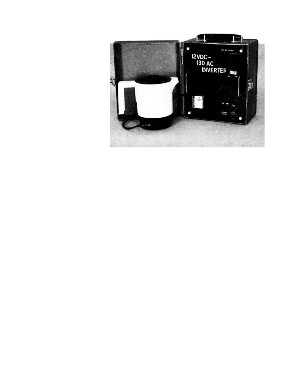
Power small appliances from
your car or any other 12-volt
source with our 250-watt
inverter.
DO YOU EVER NEED TO POWER 120-volt
ac equipment when there is no AC outlet
available? Our affordable power inverter
was designed to supply up to 250 watts to
power line-operated equipment a a fraction
of the cost of commercially built units.
The inverter described here has been used to power flood lamps, soldering irons (both resistance and transformer
Power FET's to the rescue
devices have gotten more versatile over the last few years and, at the same time.
tion unnecessary The ratings for
Operation
ws the schematic of the inverter. A 555 timer, IC1, along with R3, R2, and C2, generates a 120-Hz (+/- 2
nput of a CD4013BE dual D-type flip-flop, IC2-a, which is wired to
R4, to three inputs of IC3 a CMOS CD4050BE hex buffer.
The inputs to the buffers are also controlled by D5 and D6, which are connected to the drains of the FET's so that the
types), fans, televisions, and portable computers. It has even powered an air pump for the author's asthmatic son. The
inverter will power almost any device that runs on 120 volts AC. Some motorized devices won't work well, however. A
variable-speed drill may work, but only at one speed. Fans and other purely inductive loads seem to run at about 2/3
normal speed with the inverter. Synchronous motors will run at normal speed but will be a little "noisy.
Power FET (field effect transistor)
The prices for them have plummeted. Nothing can match a FET in its ease of interfacing with logic signals. and for the
ease in which it can work in parallel with similar devices without the need for any extra components. `lb parallel the
FET's, all you have to do is tie the source leads together. When the they get warm, FET's exhibit a positive temperature
characteristic, which means as the temperature goes up, so does the resistance; as the resistance goes up, the current
through the device Is lowered. That makes FET's self-limiting when working in parallel.
FET's are now being produced with power ratings that can often make parallel opera
the IRFZ30s that are used in this project are amazing: they can handle a 30-amp load with 50 volts across the source-
drain leads and 75-watt power dissipation, all in a TO-220AB plastic package-for less than two bucks each when
purchased in small quantities.
Figure 1 sho
Hz) signal, as set by the value of potentiometer R3.
The output of IC1 at pin 3 is fed to the CLOCK i
divide the input frequency by two; that generates the 60-Hz clocking for the FET array (Q1-Q6). The output from flip-flop
IC2-a at pin I has a 50% duty cycle, which is necessary for the output transformer. The flip-flop also provides an inverted
output (/Q pin 2), which saves us from having to add additional components to invert the Q output. The second half of
IC2 (IC2-b) is not used, so all of its input pins are grounded.
The Q and /Q outputs from IC2a are each fed, via R5 and
Each group of three buffer outputs drives one bank of FET's in the power stage.
array that is turned-on essentially has control of the drivers of the opposite array. When one side is turned on and its
drain is at ground potential, the other side cannot turn on because the input to the buffer for that array Is also being held
at ground. It stays that way until the controlling array has completely turned off and the drain voltage has gone above
about 6 volts. That is necessary because the turn-off time for a FET is longer than its turn-on time. If the diodes were
eliminated. both arrays of FET's would be turned on simultaneously during each transition, which creates tremendous
spikes on the battery, the equipment tied to the output of the inverter, and to the FET's themselves.
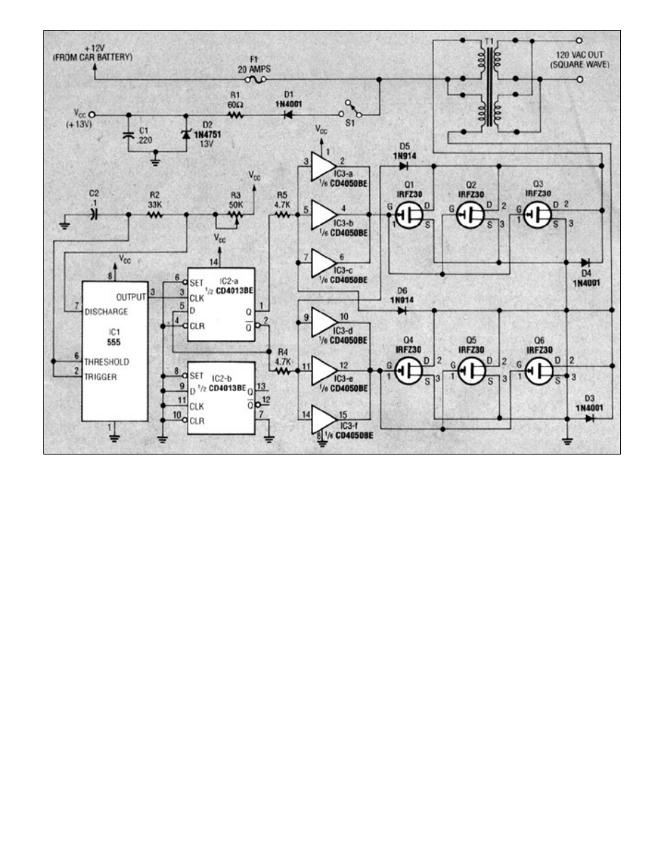
FIG. 1-INVERTER SCHEMATIC. A 555 timer (IC1) generates a 120-Hz signal that Is fed to a
CD4013BE flip-flop (IC2-a) which divides the Input frequency by two to generate a 60-Hz
clocking frequency for the FET array (Q1-Q6).
The FET array can be made as big or as little as your application requires. The author needed at least 250 watts, and
used two IRFZ30s in parallel for each array. However, to play it safe, use three in parallel (or however many you need)
for each array as we've shown in the schematic. Diodes D4 and D3 dampen inductive kickback from the transformer
winding that would likely cause overheating and premature transistor breakdown.
Power-supply conditioning circuitry (D1, RI, D2, and C1) eliminates spikes, overloads, and other noise from a car's 12-
volt supply. Even though the 555 can handle up to a 15-volt supply, power-supply spikes will surely damage it.
If the transformer you use has a center tap, the center tap must be connected to the 12-volt line and the two 12-volt
windings must be connected to the drains of their respective driving transistors. The author used a Jefferson buck/boost
transformer that's normally used to reduce or increase the line voltage for AC devices. If you are going to buy a
transformer, you can use any center-tap 24-volt or dual-winding 12-volt transformer. It is important to use a transformer
that can supply the amount of current that your application requires.
Construction
Some of the components mount on a small PC board, for which we've provided the foil pattern. The parts-placement
diagram is shown in Fig. 2. We recommend that you use sockets for the IC's. After soldering all components on the
board, apply 12 volts and measure the frequency on the pads marked J4 and J2. Adjust R3 for a reading of 60 Hz, and
make sure the voltage is very close to 1/2 of the supply voltage on each pad. That tells you that your duty cycle is 50%.
Now connect the rest of the components. The small offboard components can be mounted on a terminal strip.
However, be sure to mount the FET's on a heatsink. If the beatsink is at ground potential, also be sure to insulate the
FET's from it.
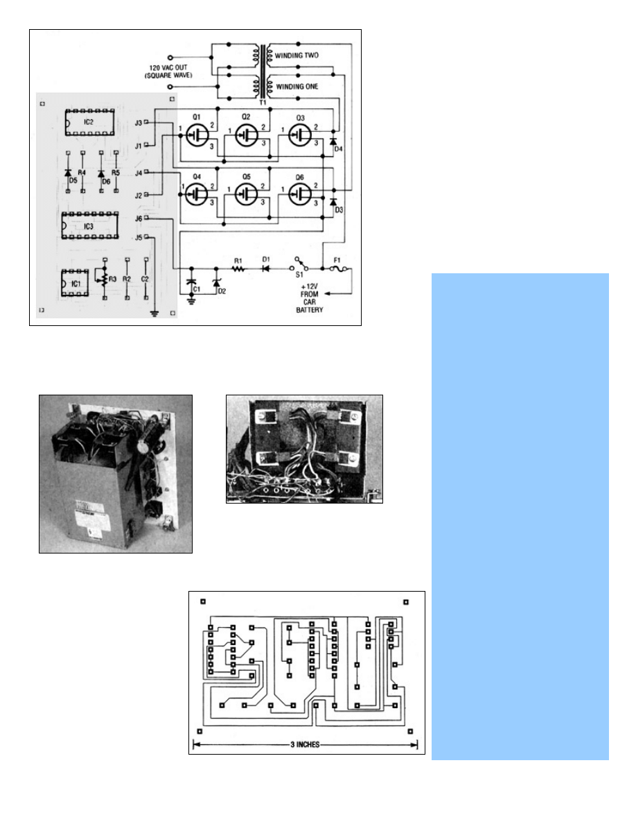
The author used a car cigarette lighter plug on
the end of the power-input lead, but you are free
to use alligator clips or whatever is most
convenient for you. A standard AC outlet was
mounted on the front panel of the unit. The
prototype was installed in an old, rugged metal
case, but you can use whatever you have on
hand. Figure 3 shows the prototype inverter and
how everything is assembled ' Figure 4 shows a
close-up view of the FET's and how they are
mounted on metal plates used as heatsinks.
Operation
To operate the unit, plug the input power into
your cigarette lighter socket, turn on the power
switch, and turn on the appliance that's plugged
into the inverter. When you are not using the
inverter, be sure to turn it off, since the
transformer will draw about 2 amps even with no
load. That will drain your car battery fairly
quickly!
PARTS LIST
All resistors are 1/8-watt, 5%,
unless otherwise noted.
R1-60 ohms, 1 watt, 10%
R2-33,000 ohms
R3-50,000 ohms, 10-turn
potentiometer
R4, R5-4700 ohms
Capacitors
Cl-220 uF 35 volts, electrolytic
C2-0.1 uF 50 volts, ceramic disk
Semiconductors
ICl-LM555 timer
IC2-CD4013BE CMOS dual D-type
flip-flop
IC3-CD4060BE CMOS hex buffer
D1, D3, D4-1N4001 diode
D2-1N4751 13-volt Zener diode
D5, D6-1N914 diode
Q1-Q6-IRFZ30 30-amp, 60-volt
FET
Other components
T1-Jefferson #216,1121 buck/
boost transformer (contact WW
Granger, Inc., 1250 Busch Pkwy,
Buffalo Grove, IL 60015, 708-
459-5445) or other 12- or 24-volt
center-tapped transformer (see
text)
S1-SPST switch
F1-20-amp fuse (or use value
according to desired output
current and transformer used)
Miscellaneous: fuse holder,
cabinet, mounting hardware, AC
outlet, car cigarette lighter plug,
wire, solder, etc.
FIG. 2-MOST OF THE COMPONENTS mount on a small PC
board. The o -board components can be mounted on a
terminal strip or perforated construction board.
FIG. 4-THE FET's ARE
MOUNTED on metal plates
used as heatsinks. If the
heatsink is at ground
potential, Insulate the FET's
from the heatsink.
FIG . 3-THE PROTOTYPE
INVERTER. The author
used a car cigarrette
lighter plug on the end of
the power-input lead and
an AC outlet for plugging
appliances Into.
FOIL PATTERN
for the Inverter
board.
Wyszukiwarka
Podobne podstrony:
200VA Power inverter
200 Watts Power Inverter Schematic
Battery Inverter For Modularly Structured Pv Power Supply Systems
HIGH POWER 100KW INVERTER
A Series Active Power Filter Based on a Sinusoidal Current Controlled Voltage Source Inverter
Adaptive fuzzy control for uninterruptible power supply with three phase PWM inverter
A Series Active Power Filter Based on Sinusoidal Current Controlled Voltage Source Inverter
A Composite Pwm Method Of Three Phase Voltage Source Inverter For High Power Applications
Performance Improvements in an arc welding power supply based on resonant inverters (1)
An Igbt Inverter For Interfacing Small Scale Wind Generators To Single Phase Distributed Power Gener
Adaptive fuzzy control for uninterruptible power supply with three phase PWM inverter
Pulse controlled inverter with variable operating sequence and wind power plant having such an inver
A Series Active Power Filter Based on Sinusoidal Current Controlled Voltage Source Inverter
Home Power Magazine Issue 032 Extract p22 Whats An Inverter
Analytical Method To Estimate The Maximum Power For A Photovoltaic Inverter System
An Active Power Filter Implemented With A Three Level Npc Voltage Source Inverter
więcej podobnych podstron