
Base ImagIR
™
Reference Manual
For LI-COR
DNA Sequencers
Version 4

ii
NOTICE
The information contained in this document is subject to change without notice.
LI-COR MAKES NO WARRANTY OF ANY KIND WITH REGARD TO THIS MATERIAL, INCLUDING,
BUT NOT LIMITED TO THE IMPLIED WARRANTIES OF MERCHANTABILITY AND FITNESS FOR A
PARTICULAR PURPOSE. LI-COR shall not be liable for errors contained herein or for incidental or
consequential damages in connection with the furnishing, performance, or use of this material.
This document contains proprietary information which is protected by copyright. All rights are reserved. No part
of this document may be photocopied, reproduced, or translated to another language without prior written consent
of LI-COR, Inc.
©
Copyright 1998, LI-COR, Inc.
Printing History
New editions of this manual will incorporate all material since the previous editions. Update packages may be
used between editions which contain replacement and additional pages to be merged into the manual by the user.
The manual printing date indicates its current edition. The printing date changes when a new edition is printed.
(Minor corrections and updates which are incorporated at reprint do not cause the date to change).
Epson
®
is a registered trademark of Seiko Epson Corporation. Microsoft
®
and Windows
®
are registered
trademarks of Microsoft Corporation. IBM
®
, OS/2
®
and PS/2
®
are registered trademarks and Presentation
Manager™ and XGA™ are trademarks of International Business Machines Corporation. Base ImagIR™ is a
trademark of LI-COR, inc.
The Model 4200 Automated DNA Sequencer and LI-COR chemical reagents are produced and distributed for
research purposes only. In no instance is any product offered for drug or clinical use in humans.
LI-COR and/or University of Nebraska patent numbers: U.S., 4,729,947; 5,207,880; 5,230,781; 5,346,603;
5,360,523; 5,366,603; 5,549,805; Canada, 1,230,161; Australia, 662273; 670622; Europe, 157,280; 533,302;
Japan, 2007209. Other U.S. and foreign patent applications pending.
Publication Number 9801-120
LI-COR, Inc. • 4308 Progressive Ave. • Lincoln, Nebraska USA 68504
Phone: 402-467-0700 • FAX: 402-467-0819 • Toll-free 1-800-645-4267 (U.S. & Canada)
e-mail: biohelp@bio.licor.com
Internet: http://www.licor.com

iii
Base ImagIR
™
Software Product
License Agreement and Limited Warranty
License Agreement
Please read this license carefully before using the Base ImagIR programs. By using the programs you agree to
the terms of this license.
The enclosed computer program(s) is licensed, not sold, to you by LI-COR, inc. for use only under the terms of
this License, and LI-COR reserves all ownership and title to the Program, as well as rights not expressly granted to
you. You own the disk on which the Program is recorded, but LI-COR retains the ownership of all copies of the
Program itself.
Permitted Uses. This license allows you the non-exclusive rights to:
1) Use the software on a single computer;
2) Retain one (1) copy of the Program solely for archival purposes. Customer agrees that no warranty, free
installation, or free training is provided by LI-COR for copies or adaptations made by Customer.
Prohibited Uses. This license does not allow you to:
1) Electronically distribute the Program from one computer to another over a network;
2) Distribute or sell copies of the Program or documentation to others;
3) Modify, alter, decompile, disassemble, reverse-engineer, adapt, or translate the Program, any portion thereof,
or documentation without the prior written consent of LI-COR;
4) Rent, lease, sub license, or otherwise make the Program available to others who have not been individually
licensed by LI-COR, including computer services, networks, timesharing or other multiple-user arrangement;
5) Merge it with another program or create derivative works based on the Program.
Duration. This License is effective upon initial use of the Program, and continues until terminated. This License
will terminate immediately if you fail to comply with the terms of this License. Upon termination, you must
destroy the Program and all copies thereof, and all related documentation. You may terminate this License at any
time by destroying the Program and all copies thereof, and all related documentation.
Transfer of Rights
1) Customer may transfer rights in the software to a third party only as a part of the transfer of all of their rights
and only if Customer obtains the prior agreement of the third party to be bound by the terms of this License.

iv
2) Upon such a transfer, Customer agrees that their rights in the software are terminated and that they will either
destroy their copies and adaptations or deliver them to the third party.
Limited Warranty
Software:
LI-COR warrants for a period of 90 days from the date of purchase that the product will execute its instructions
when properly installed on the computer indicated in its instruction manual. LI-COR does not warrant that the
software is free from errors or interruptions. In the event that this software product fails to execute its
programming instructions during its warranty period, customer should contact LI-COR. If the problem cannot be
resolved in a reasonable amount of time, the customer's recourse is to return the software to LI-COR for a refund.
Media:
LI-COR warrants the computer disks (3 1/2" and optical) upon which this software is recorded to be free from
defects of material or workmanship under normal usage for a period of 90 days from the date of purchase. Should
the disk(s) prove to be defective during the warranty period, the customer's recourse is to return the media to
LI-COR for replacement.
Upgrade Policy:
This License entitles you to receive Base ImagIR software upgrades for a period of two (2) years from the date of
purchase at no charge.
Limitation of Warranty:
There are no warranties, express or implied, including but not limited to any implied warranty of merchantability of
fitness for a particular purpose with respect to this product.
Other than the obligation of LI-COR, inc. expressly set forth herein, LI-COR, inc. disclaims all warranties of
merchantability or fitness for a particular purpose. The foregoing constitutes LI-COR, inc.'s sole obligation and
liability with respect to damages resulting from the use or performance of the product and in no event shall
LI-COR, inc. or its representatives be liable for damages beyond the price paid for the product, or for direct,
incidental or consequential damages.
The laws of some locations may not allow the exclusion or limitation on implied warranties or on incidental or
consequential damages, so the limitations herein may not apply directly. This warranty gives you specific legal
rights, and you may already have other rights which vary from state to state. All warranties that apply, whether
included by this contract or by law, are limited to the time period of this warranty which is a 90-day period
commencing from the date the product is shipped to the customer.

v
Welcome to Base ImagIR
™
Welcome to Base ImagIR, the software set dedicated to
collecting and analyzing DNA sequence data from the
LI-COR Automated DNA Sequencers. This preface describes
the key features of the Base ImagIR software, and tells how to
get on-line help information.
If you have never used OS/2
®
or Windows
®
operating
systems, you may want to read the OS/2 section later in this
manual.
What is Base ImagIR?
Base ImagIR is a software set containing several programs that
are used to collect, analyze, and otherwise manipulate image
data collected with LI-COR DNA Sequencers.
Base ImagIR runs under IBM's OS/2
®
operating system,
which provides a powerful platform for true multitasking
operations. Under OS/2, up to two sequencers can be operated
from a single host computer. Multitasking also makes it
possible to call bases in real time as image data are collected
during electrophoresis.
Data Collection
The Data Collection program performs gel electrophoresis
with the LI-COR sequencer. Power supply settings for
electrophoresis and many other parameters can be edited on
screen and sent to the sequencer. During Data Collection the
autoradiogram-like image is collected in real time for
immediate verification of the success of the sequencing

vi
reactions. Operating parameters are stored in configuration
files for consistency between runs.
Image Analysis
Image Analysis calls bases from the sequence image obtained
during Data Collection. Briefly, Image Analysis allows the
user to sequence one or all of the samples on a sequence image
either automatically, semi-automatically, or manually.
Image Manipulation
Image Manipulation is used with existing sample and/or image
files to crop, print, and save in alternate file formats. Image
files can be printed with sequence text, band markers, and with
enhancements such as brightness and contrast.
Quick SequencIR
Quick SequencIR completely automates Data Collection and
Image Analysis. When Quick SequencIR is run, Data
Collection is opened, and begins collecting image data based
on the electrophoresis parameters set in a user-defined
configuration file. Image Analysis is then opened, which will
automatically finds the lanes and begins sequencing the
samples.
On-line Help
Brief descriptions of Base ImagIR commands, dialog boxes
and windows are available at all times through the on-line
help. Detailed information about the on-line help system is
available later in this section.
vii
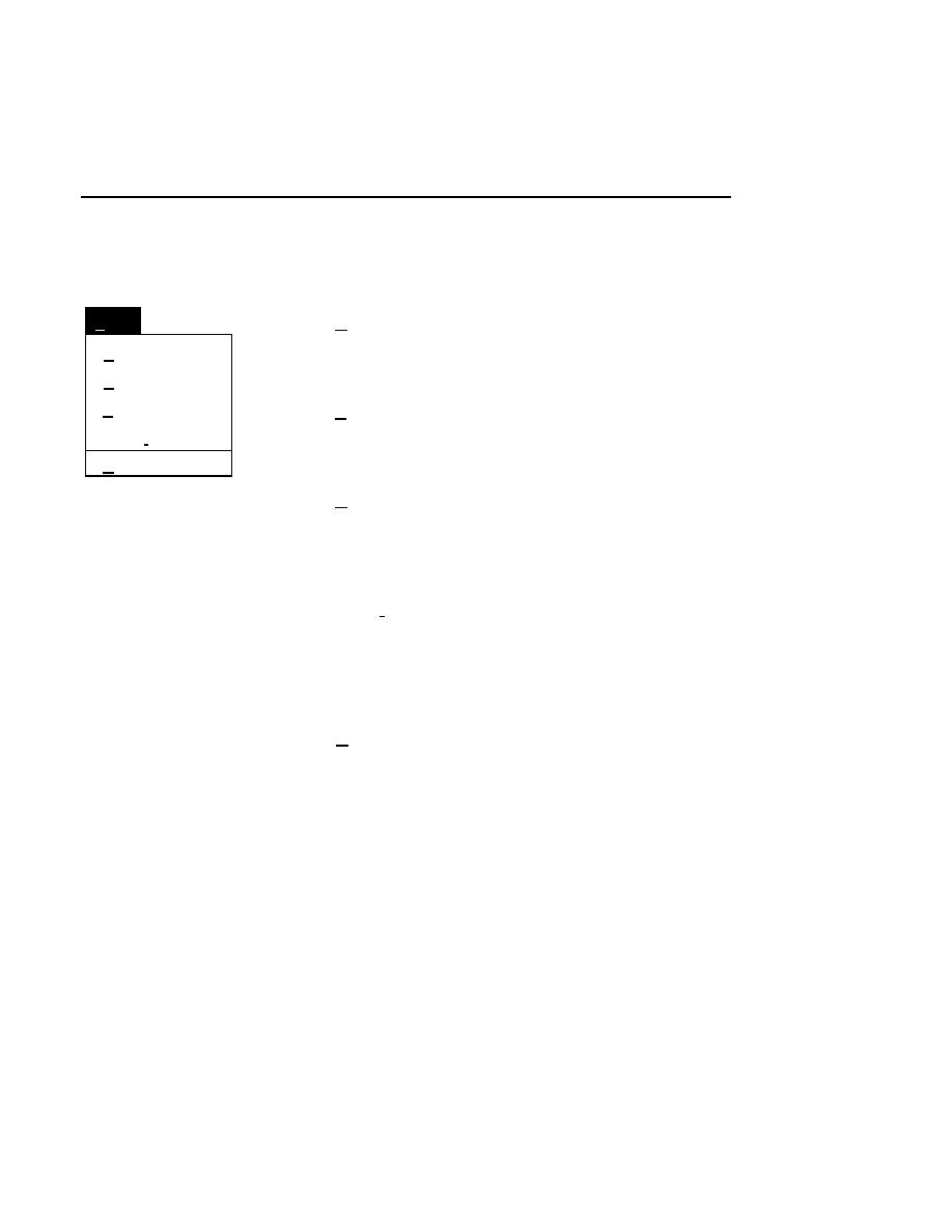
What's Included in Base ImagIR?
Base ImagIR was installed at the factory, and a back-up copy
is included on optical disk. As shown in the OS/2 Drive C
directory tree window below, Base ImagIR is installed in the
DNA4200 directory on drive C, with one or more
subdirectories.
Drives - Icon View
Drive C - Tree View
C: 92,962 KB free, 153,584 KB total
Drive C:\DNA4200
Drive A
Drive B
Drive C
Drive D
Drive C
OS/2
help
DNA4200
Tutorial

viii
The contents of these directories are as follows:
This directory
contains
...
DNA4200
ANL.EXE
- Image Analysis program.
COL42.EXE
- Data Collection program.
IMG.EXE
- Image Manipulation program.
VWSCF.EXE
- SCF ViewIR program.
PRSCF.EXE
- SCF PrintIR program.
QUICK42.EXE
- Quick SequencIR
program.
MKSCF.EXE
- SCF Converter program.
DEFAULT.COL
- Default configuration
parameters for Data Collection program.
DEFAULT.ANL
- Default configuration
parameters for Image Analysis program.
COLCFG.EXE
- Data Collection
configuration program.
ANLCFG.EXE
- Image Analysis
configuration program.
SAMPLE.SNT
- An example of a Sample
Notepad template file.
IMAGE.INT
- An example of an Image
Notepad template file.
UPDATE.CMD
- Program for updating the
Base ImagIR software.
Programs may be added or removed over time.
Registration
LI-COR provides free technical support to all DNA Sequencer
users. In order to take advantage of this service, please
complete the enclosed registration information. In addition,
we must have a current address to ensure that you receive

ix
future newsletters, product announcements, and upgrade
notices.
If you need technical assistance, call toll-free 1-800-645-4267
in the U.S. and Canada, or 402-467-0700. Applications
scientists are available Monday through Friday between 8 a.m.
and 5 p.m. Central Standard Time.
About this Manual
This manual is divided into sections corresponding to the
various Base ImagIR programs. You may periodically receive
updates to these sections, and in some cases you will be asked
to replace entire sections with more current materials.
On-line Help Information
General Information
On-line help is available at all times in the Base ImagIR
software programs. The help windows are intended to provide
information about menu choices, windows, dialog boxes, or
applications. The help window displayed is determined by the
object that is highlighted when help is requested.
How to Access Help Information
Help information can be accessed in any of three ways; by
pressing the
F1
function key when a field or choice is selected,
pressing the Help button in a dialog box, or by choosing one of
the choices in the Help pull-down menu.
For example, pressing
F 1
while the
New
menu choice is
selected will open a help window, as shown below.
x
Base ImagIR Data Collection
Help
Options
Services
New Image File
Select New on the File pull-down menu to Open a new
image file and to initiate Data Collection.
When you select New, the
New
dialog appears. Use
this dialog to enter a file name, remarks (optional) and
the directory in which you want the file to appear.
The New menu choice is not active if a file is already
open.
RELATED TOPICS
File Names and Types
Opening Existing Image Files
Image Remarks
Data Collection Overview
Closing and Quitting Data Collection
+
F1
Index
Print...
Search...
Previous
Remarks...
Close...
Open...
Exit
F3
File
Ctrl+R
New...
Pressing F1 while a choice is selected opens the related help window.
In addition, some help windows contain 'Hypertext' words or
phrases that are highlighted in a different color. To obtain
more information about this word or phrase, double-click the
mouse button on it, or press
Tab
until the cursor is located on
the word(s) and press
Enter
.
When help windows are displayed, other features of the help
system can be accessed through the help window pull-down
menus.
Help windows are dismissed in any of the following ways:
1.
Choosing
Close
from the help window system menu.
2.
Double-clicking on the system menu icon.
3.
Pressing <Esc>.
4.
Closing the application window to which the help infor-
mation is related.

Data Collection
1-1
Data Collection
Table of Contents
Section 2. Scanner Control Window
Overview ...................................................
Starting Data Collection ............................
File Menu...................................................
New ....................................................
Open ...................................................
Close ...................................................
Exit .....................................................
Window Menu ...........................................
Cascade...............................................
Help Menu .................................................
Help for help.......................................
Extended help .....................................
Keys help............................................
Help index ..........................................
About ..................................................
Editing the Operating Parameters ..............
Moving the Operating Parameters ............
Parameters Menu .......................................
Send ....................................................
Load configuration .............................
Reset ...................................................
Log list ................................................
Copy Menu ................................................
Log list ................................................
Selected ..............................................
All .......................................................
Options Menu ............................................
Focus ..................................................

1-2
Data Collection
Overview ...................................................
Changing the Window Display ..........
Goto Menu .................................................
Tab .....................................................
Frame .................................................
1/4 page up .........................................
1/4 page down ....................................
View Menu ................................................
Auto scroll ..........................................
Set tab .................................................
Clear tab .............................................
White on Black/Black on White.........
Delete Image ......................................
Show gain/offset .................................
Send gain/offset..................................
Enhancement Menu ...................................
Intensity adjustment ...........................
Image size ...........................................
Options Menu ............................................
Auto gain ............................................
Title bar ..............................................
Remarks .............................................
Section 4. Configuration Window
General Overview .....................................
Open ...................................................
Save ....................................................
Save as................................................
Save as DEFAULT.............................
Default ................................................
Reset ...................................................
Help ....................................................
Path Notebook Page ..................................
Power Supply Control Notebook Page ......
Heater Control Notebook Page ..................
Scan Control Notebook Page.....................
Image Notebook Pages ..............................
Notes Page .................................................
Parameters Log List Notebook Page .........
Exit Options Notebook Page .....................
File Menu...................................................
New ....................................................
Save ....................................................
Autosave .............................................
Print ....................................................
Edit Menu ..................................................
Cut ......................................................
Copy ...................................................
Paste....................................................
Clear ...................................................

Data Collection
1-3
Opening the Notepad in Data Collection...
File Menu...................................................
New ....................................................
Open ...................................................
Save ....................................................
Autosave .............................................
Print ....................................................
Edit Menu ..................................................
Cut ......................................................
Copy ...................................................
Paste ...................................................
Clear ...................................................
Delete .................................................
Find.....................................................
Select all .............................................
Options Menu ............................................
Wordwrap ...........................................
Opening the Notepad in Image Analysis ...
File Menu...................................................
New ....................................................
Save ....................................................
Autosave .............................................
Print ....................................................
Edit Menu ..................................................
Cut ......................................................
Copy ...................................................
Paste....................................................
Clear ...................................................

Section 1
1-4
Data Collection
Overview
The Base ImagIR Data Collection program collects and stores
image data during gel electrophoresis and stores it in an image
file. Base ImagIR is capable of collecting image data from as
many as two sequencers simultaneously. Other operations,
including Image Analysis, can be performed during the Data
Collection operation, due to the multitasking nature of the
OS/2 operating system.
Each sequencer must have its operating parameters set before
electrophoresis can begin. These parameters include the
voltage, current, and power applied to the gel apparatus, the
heater plate temperature, the number of frames of data to
collect, etc. These parameters and their usage are explained in
detail in the Operator's Manual for the sequencer.
Default values for the operating parameters can be edited and
saved in distinct configuration files.
After gel electrophoresis, Image Analysis is used to recall the
image to the monitor and sequence each of the samples.
Both Data Collection and Image Analysis can be fully
automated using the Quick SequencIR program (see Auxiliary
Programs).
Data Collection
Data Collection
1-5
Starting Data Collection
Data Collection is opened by double-clicking the Data
Collection icon in the Base ImagIR folder. The Data
Collection window is displayed:
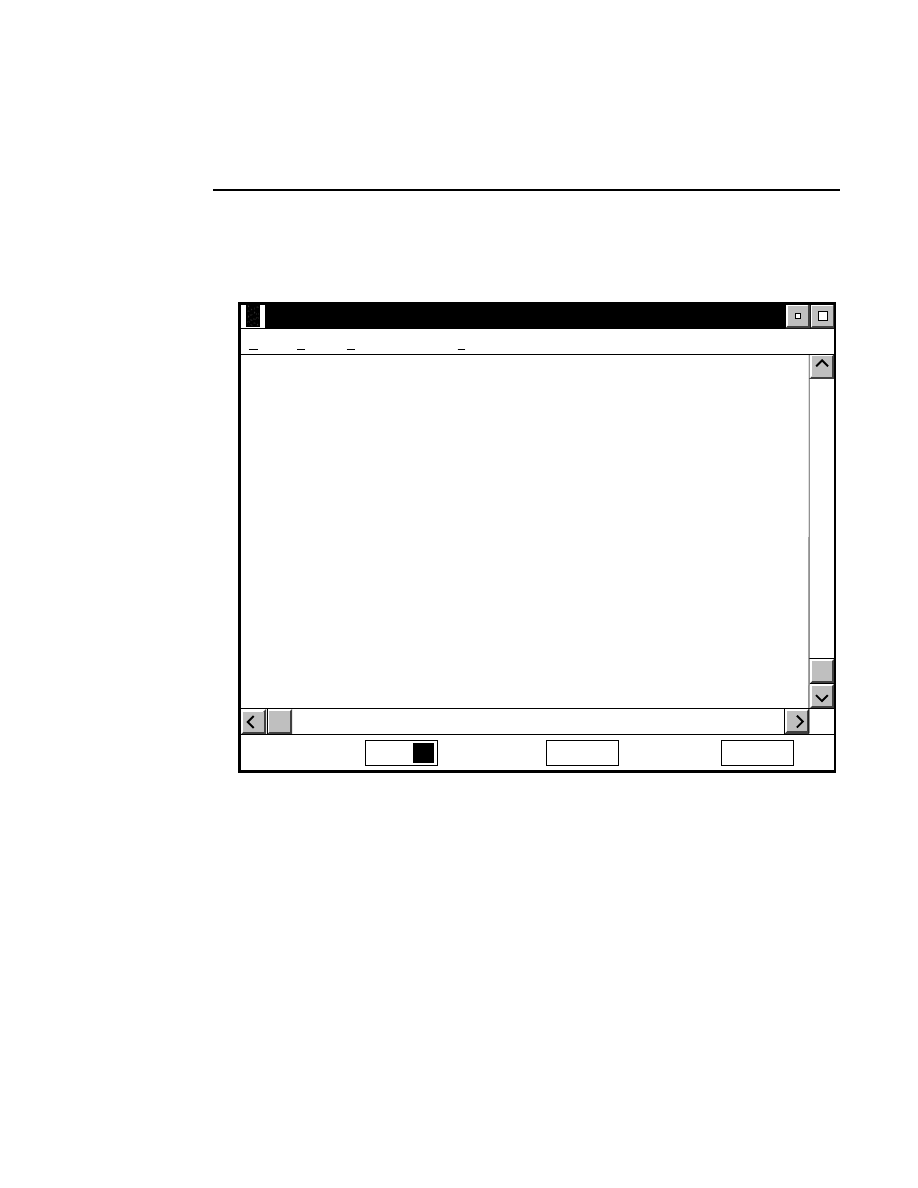
Base ImagIR Data Collection <NULL><Untitled>
File Window Help
i
Messages
Configuration
Cfg
There are three menu items in the Data Collection window; the
File, Window, and Help menus.
Also present are icons to open the Message window and the
Configuration window. When an image file is created or
opened, the Image window and icons to open the Image and
Log Notepads will be displayed.
Section 1
1-6
Data Collection Window - File Menu
File Menu
New...
Open...
Close...
Exit
File
F3
The File menu contains four commands related to managing
the image file(s).
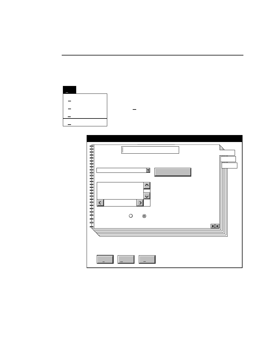
New...
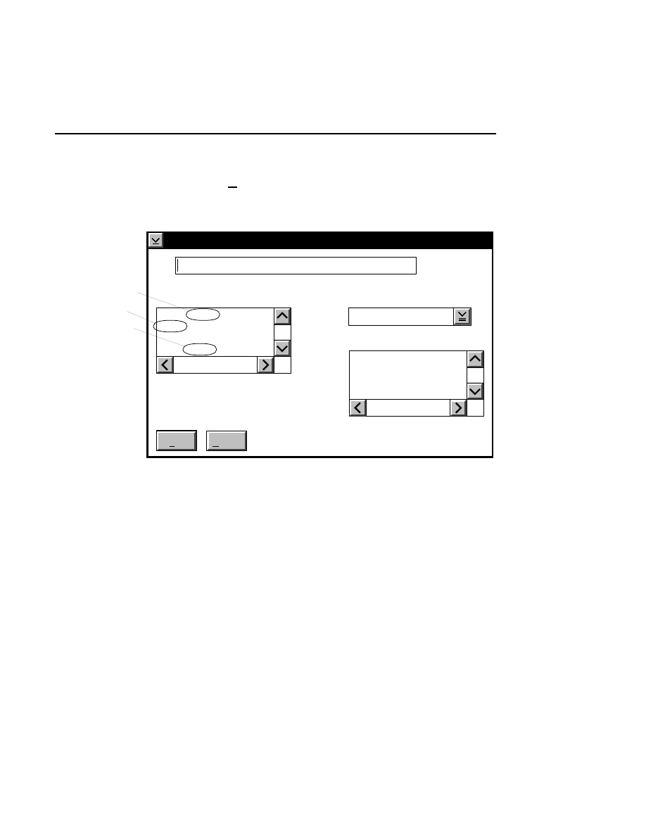
Allows you to create one or two new image files. A dialog
box is presented in which you can name the file(s) and enter
remarks. The New dialog has three pages, as described below.
New
Cancel
Help
OK
Project name:
C:
..
Pixel size (bits): 8 16
Create Directory...
Space available: 155641 KB
Space required (per frame): Approx. 1536 KB
Path: C:\DNA4200\data
Drives:
Directories:
Project
800
700

Data Collection
Data Collection Window - File Menu
1-7
Project Tab
To change the path, double-click on the desired directory in
the Directories list box. Double-click on the “••” in the
Directories list box to move one level higher in the Path
hierarchy. For example, if the path listed is C:\DNA4200,
double-clicking on “••” will change the path to the root
directory (C:).
The 'Space Available' text field indicates the amount of disk
space currently available on the computer's hard disk. Check
the available space before starting a new file, as 8-bit image
files collected on a 41 cm gel average 8 - 12 megabytes
(images collected in 16-bit mode will require twice the disk
space).
The date, time, and device number of the sequencer that
corresponds to the current Data Collection program appear in
the Image Remarks text box. These remarks can be deleted or
edited. Up to 500 characters can be entered. These remarks
are visible in the New and Open dialog boxes in Image
Analysis.
If you want to create a subdirectory to store the image and
related files, click on the Create Directory button. The Create
Directory dialog box is displayed.
Enter the path and name of the directory to be created (up to
32 characters). Click
Create
to save the new directory. If no
path is specified, the new directory will be saved as a
subdirectory of the 'Path' in the New dialog box.
Section 1
1-8
Data Collection Window - File Menu
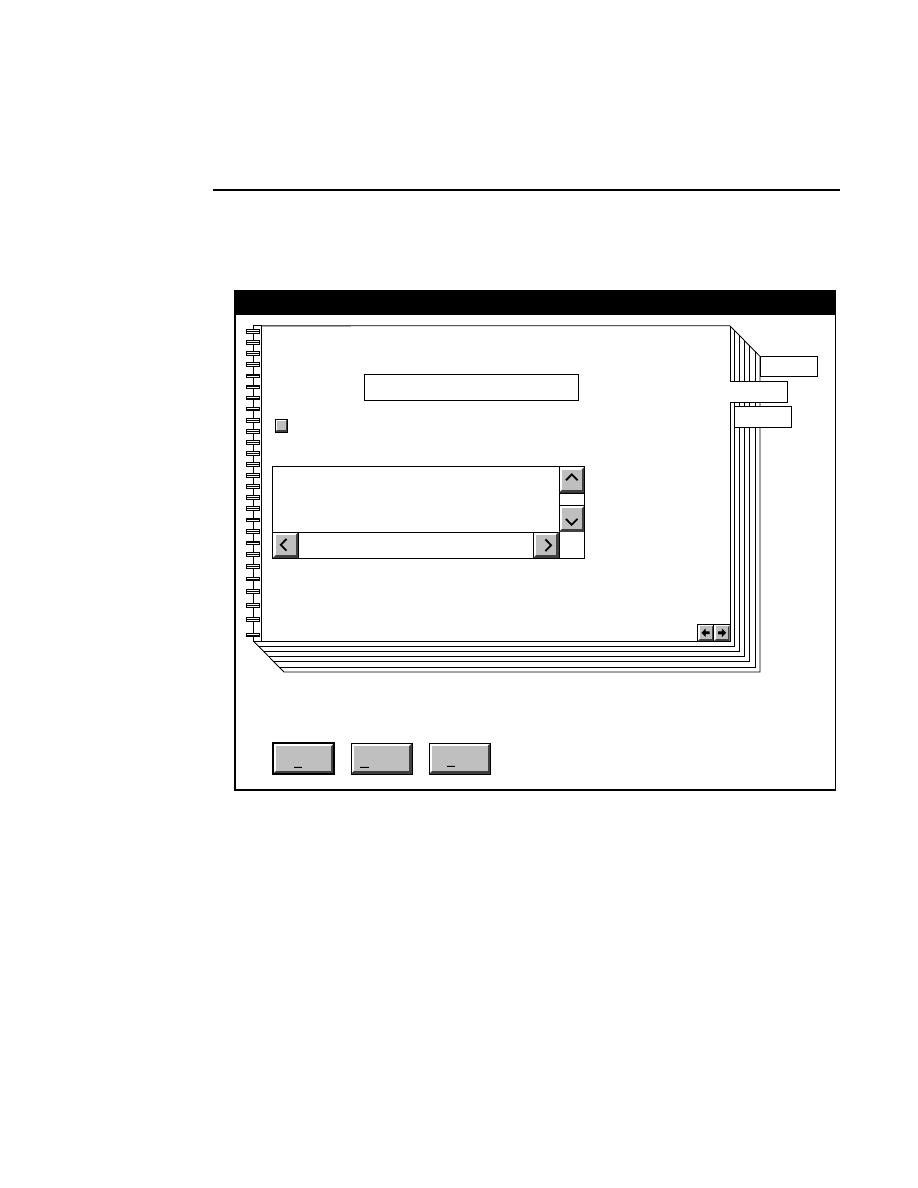
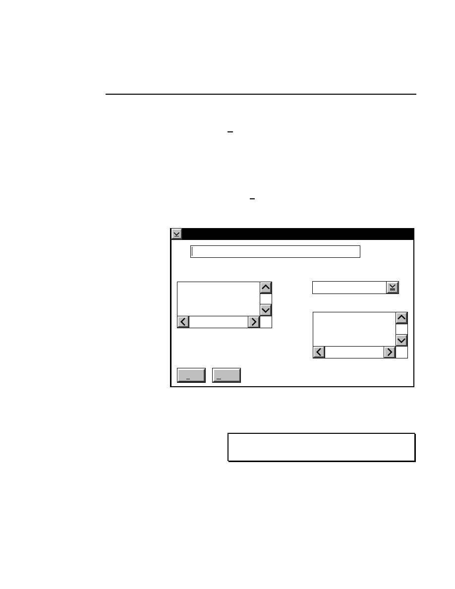
800 Tab
New
Cancel
Help
OK
Image name:
Collect
01-04-98 09:19:07 NULL
Space available: 155641 KB
Space required (per frame): Approx. 1536 KB
800
Remark:
Project
800
700
✔
N1
Enter the filename for the image to be collected on channel 1
in the 'Image name' text entry field. A .TIF extension will
automatically be added. The image file collected on channel 1
will be saved to the project directory listed in the preceeding
Project page. The image file name is also used to name the
Image and Log Notepad files, which are given the extensions
Data Collection
Data Collection Window - File Menu
1-9
.INT and .LOG, respectively. When Data Collection is closed,
a file of last-used electrophoresis parameters is also created
with the same name, and is given the extension .CWR.
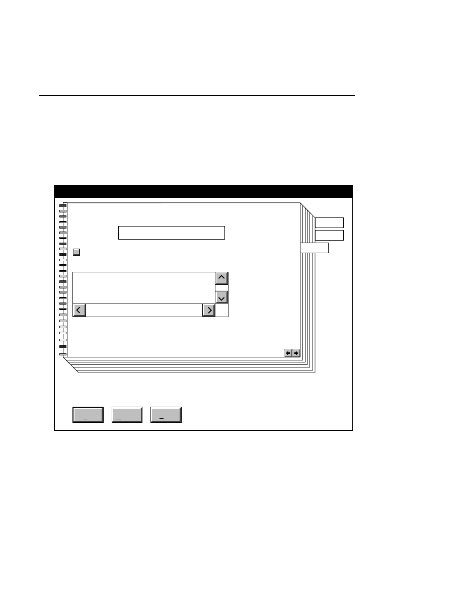
700 Tab
New
Cancel
Help
OK
Image name:
Collect
01-04-98 09:19:07 NULL
Space available: 155641 KB
Space required (per frame): Approx. 1536 KB
700
N2
Remark:
Project
800
✔
700
Enter the filename for the image to be collected on channel 2
in the 'Image name' text entry field. A .TIF extension will
automatically be added. The new image file (and all

Section 1
1-10
Data Collection Window - File Menu
associated files) collected on channel 2 will also be saved to
the project directory listed in the preceeding Project page.
When you have finished entering the file names, press
OK
to
close the New dialog box.
Collecting Image Data on a Single Channel
If you choose to collect image data on only one channel, go to
the page for the channel that you do not want to use, and
deselect the 'Collect' check box.
Data Collection
Data Collection Window - File Menu
1-11
New...
Open...
Close...
Exit
File
F3
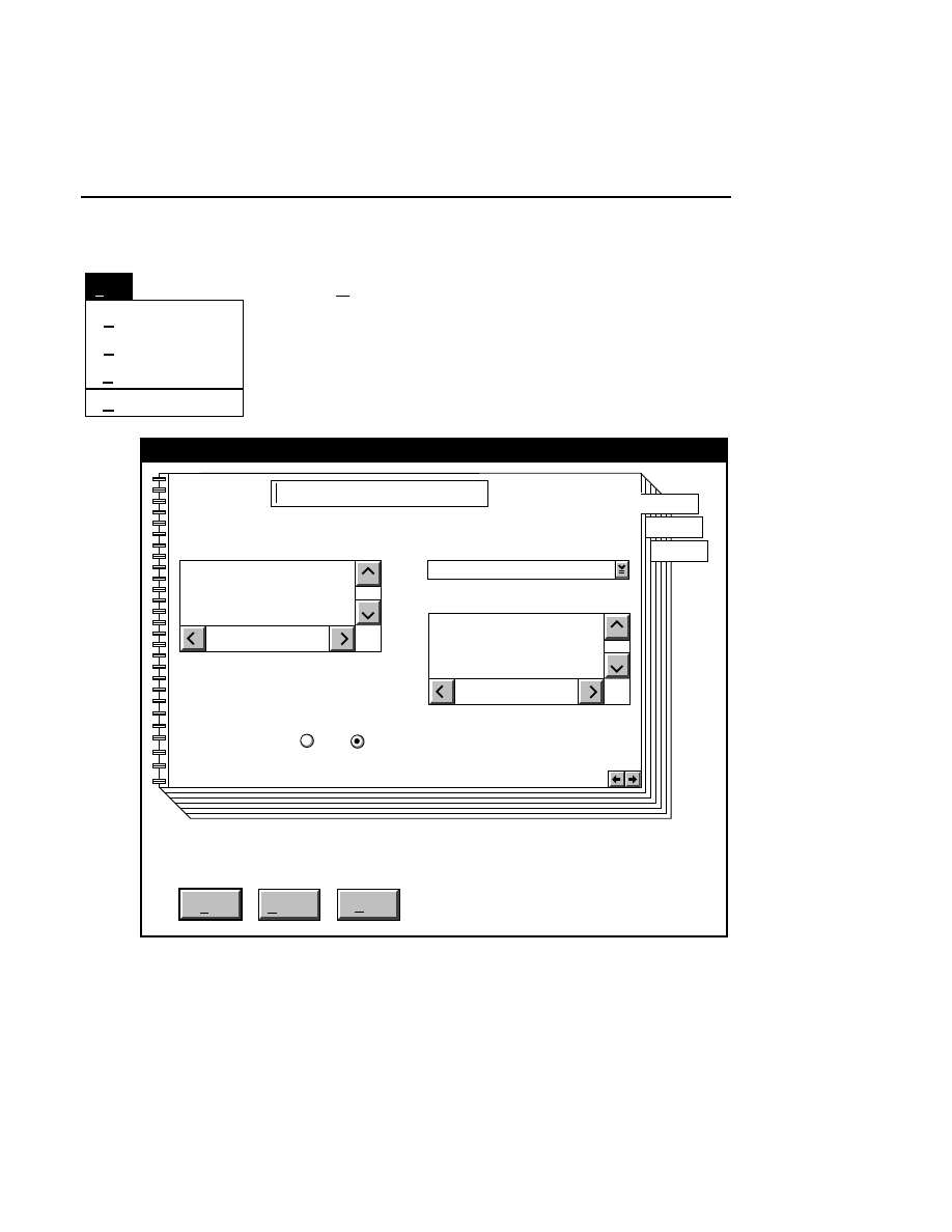
Open...
The Open command loads an existing image file and displays
it in an image window. Although it is not recommended, new
image data can also be appended to the end of an existing
image file. Select Open to bring up the Open dialog box:
Open
Cancel
Help
OK
Project name:
C:
..
Pixel size (bits): 8 16
Space available: 155641 KB
Space required (per frame): Approx. 1536 KB
Path: C:\DNA4200\data
Drives:
Directories:
..
Projects:
Project
800
700
There are two ways to open existing image files:

Section 1
1-12
Data Collection Window - File Menu
1.
Type the path and name of the project file in the 'Project
name' text entry field, and click
OK
.
2.
Use the Drives and/or Directories list boxes to select the
appropriate path. Select the desired Project file in the list
box, and click
OK,
or
double-click on the desired project
file.
800/700 Tabs
If two image files were collected for this project, they will
both be opened. You can choose to append image data to one
or both image files by enabling the 'Collect' check box in each
image window, as shown below.
Data Collection
Data Collection Window - File Menu
1-13
Open
Cancel
Help
OK
Image name:
01-04-98 09:19:07 NULL
Space available: 155641 KB
Space required (per frame): Approx. 1536 KB
800
Remark:
Project
800
700
Collect
✔
When you have located the image file(s), press
OK
to close the
Open dialog box.
The image remarks text box displays the image remarks made
when the image file was created. These remarks cannot be
edited in the Open dialog box.
When an image file is opened, the associated Log and Image
Notepads are also opened.
Section 1
1-14
Data Collection Window - File Menu
New...
Open...
Close...
Exit
File
F3
Close...
Closes and saves the active image file(s) and all related files.
The high voltage power supply and the scan motor will be
turned off, and the heater plate setpoint will be set to zero.
Data Collection stays open. When Close is selected, a
message box appears, alerting you that the High Voltage and
Scan Status will be turned off, and the Heater plate
temperature will be set to 0
°
C (Off). Select
OK
to close the
file(s), or
Cancel
to return to Data Collection without closing
the file(s).
Data Collection
Data Collection Window - File Menu
1-15
New...
Open...
Close...
Exit
File
F3
Exit
F3
The Exit dialog box alerts you that the scanning motor, high
voltage power supply, and heater plate will be turned off (if
they are currently on) when Data Collection is closed. Note,
however, that these parameters can be set in the configuration
window to remain on when Data Collection is closed. See
Section 4, Configuration Notebook for more details.
Leaving the heater plate on can be useful if you are going to
perform another electrophoresis run, as it will not be necessary
to warm the plate again before pre-electrophoresis.
Select
OK
to exit the program, or
Cancel
to close the dialog
box without leaving Data Collection.
Section 1
1-16
Data Collection Window - Window Menu
Window Menu
1.Messages
2.Configuration
Window
Cascade
Shift+F5
3.Scanner Control
✓
4.Image Notepad
5.Log Notepad
6.Image : 1
7.Image : 2
Cascade
Shift + F5
Aligns the windows with a stairstep overlap. The title bar of
each window is visible and the active window is on top.
The active window is denoted by a ✓ (check mark) before the
menu item. Selecting any of 1-7 will cause the associated
window to open, or to become active (the title bar will be high-
lighted, and the window will move to the front).
Data Collection
Data Collection Window - Help Menu
1-17
Help Menu
Help for help
Extended help
Keys help
Help index
About...
Help
Help for help
Opens a window describing the use of help screens.
Extended help
Displays a brief overview of the Data Collection program.
Keys help
Gives a description of the keyboard shortcuts for each Data
Collection window.
Help index
Contains a listing of topics for which help information is
available. Double-click on the listing to open the help
information for the selected topic.
About...
Displays the Data Collection startup screen, which shows the
software version number of the program.

Scanner Control Window
2-1
Scanner
Control Window
The Scanner Control window is used to set the operating
parameters and transmit them to the sequencer.
The operating parameters can be edited at any time during gel
electrophoresis, and sent to the sequencer for implementation.
There are 16 operating parameters shown in the Scanner
Control window, of which 8 can be edited. These parameters
may also be edited using the Sequencer keypad - see the
Operator's Manual for details.
The Scanner Control window and the sequencer are
interactive, meaning that the operating parameters set in the
Scanner Control window are continually updated as the
Sequencer transmits the real-time values of the set parameters
back to the computer.
The operating parameters listed in the Scanner Control
window are as follows:
●
Interlock Status (Open/Closed) - The sequencer has three
safety interlocks which prevent exposure to the laser and
high voltage power supply during operation. These
interlocks are located on the front and rear doors, and on
the lower buffer tank. If any of these interlocks are
violated, the laser and power supply shut down, and the
Interlock Status parameter reads 'Open'. All three
interlocks must be closed before scanning can begin.
Section 2
2-2
Scanner Control Window
●
Time (HHMMSS) - The Time parameter displays the
current time in HHMMSS format, using a 24-hour clock.
When the parameters in the Scannner Control window are
sent to the Sequencer for the first time, the computer sends
the system time to the sequencer. When the Sequencer
transmits data back to the computer, the system time is
displayed in the Scanner Control window, along with the
other operating parameters.
If you want accurate time and date parameters, you should
set the time and date in the OS/2 operating system before
starting Data Collection. See "date & time, setting the
system clock" in the Master Help Index for information on
setting these parameters.
NOTE: If the system time and/or date are changed
after Data Collection is running, the parameter(s) will
not be updated in the Scanner Control window until a
new Data Collection session is started.
●
Date (YYMMDD) - displays the current date in
YYMMDD. The date and time are set in the OS/2 Control
Panel, which can be accessed from the System Setup icon
in the OS/2 System Window on the desktop.
●
High Voltage Status (On/Off) - indicates that the High
Voltage Electrophoresis Power Supply is On or Off.
●
Scan Status (On/Off) - indicates that the scanning laser
microscope is On or Off.

Scanner Control Window
Scanner Control Window
2-3
●
Voltage - displays the voltage (in Volts) applied across the
electrophoresis apparatus by the High Voltage Power
Supply.
●
Current - displays the current (in milliamps) applied
through the electrophoresis apparatus.
●
Power - displays the power (in Watts) being applied to the
electrophoresis apparatus.
●
Heater - displays the temperature (
°
C) of the heater plate
for the electrophoresis apparatus, where 0
°
C is off.
●
Signal Filter (1-3) - The signal filter determines the
amount of electronic filtering of the image signal. Values
of 1, 2, or 3 can be selected, where 3 is the least amount of
filtering, and 1 is the most. The frequency responses for
the signal filters are as follows: 1 = 15 Hz, 2 = 61 Hz, and 3
= 122 Hz.
For normal operation, the signal filter should always be set
to 3. Other settings can be used when changing the scanner
motor speed for alternate data collection protocols as
explained in the Operator's and DNA Sequencing Manuals.
●
Scan Speed (1-4) - sets the scan speed of the laser
microscope assembly, where 1 (Slowest) = 1.4 cm s
-1
, 2 =
2.8 cm s
-1
, 3 = 5.4 cm s
-1
, 4 (Fastest) = 10.2 cm s
-1
. The
default setting is 3.
●
Laser Status (On/Off) - displays the condition of the
laser. This parameter can not be edited from the computer.
●
Detector Status (On/Off) - displays the status of the
detector. This parameter can not be edited from the
computer.

Section 2
2-4
Scanner Control Window
●
Start Position (0) - displays the starting position of the
scanning microscope, with zero as its furthest position to
the left edge of the gel apparatus, and 6 as its position at the
right edge of the gel apparatus. This parameter cannot be
edited in the Scanner Control window; it is changed with a
command line parameter (see Appendix C).
●
End Position (6) - displays the ending position of the
scanning microscope, with zero as its furthest position to
the left edge of the gel apparatus, and 6 as its position at the
right edge of the gel apparatus. This parameter can not be
edited in the Scanner Control window.
●
Video Data (8-/16-bit) - displays the mode in which data
are collected.

Scanner Control Window
Scanner Control Window
2-5
Selecting and Editing the Operating Parameters
As mentioned earlier, many operating parameters can be
edited. The right column displays the set values, and the
middle column shows the actual values returned from the
sequencer. The set values are selected and/or edited in any of
four ways:
1
.
By dragging the I-beam cursor over the set value shown in
the text box (for example, the voltage box), and typing in
the new value.
2
.
By checking either of the On or Off radio buttons (e.g.,
Scan Status).
3
.
By clicking on the arrow box, scrolling to, and selecting
the new value (e.g., Motor Speed).
4
.
By editing the values in the Configuration window and
selecting
Load configuration
from the Parameters menu
in the Scanner Control window. The values in the
Configuration window will be sent to the Scanner Control
window.
When the operating parameters have been edited but not sent,
the text will be highlighted in red. When the parameters are
sent to the sequencer, by selecting
Send
from the Parameters
menu, or by pressing
Enter
, the text will change to black
again.
Section 2
2-6
Scanner Control Window - Parameters Menu
Moving the Operating Parameters in the Window
The parameters in the Scanner Control window can be
arranged in any order. Suppose that you want to arrange and
size the Scanner Control window so that only the Voltage,
Power, Current, and Heater parameters are visible. To do this,
place the pointer over the Voltage parameter, click the right
mouse button, hold, and drag the field to the top of the
window (the selection will change color when the right mouse
button is pressed). Release the mouse button, and the Voltage
field will be placed at the top of the list. Repeat this process
and move the Power, Current, and Heater fields below the
Voltage parameter. The window borders can then be dragged
to reduce the window size, so that only these parameters are
visible.
Parameters Menu
Load configuration
Reset
Parameters
Send
Enter
Log list...
Send
Enter
Transmits the set values in the Scanner Control window to the
sequencer, where any changes are incorporated.
Load configuration
Loads the operating parameter values from the active
configuration file into the Scanner Control window, but does
not send the parameters to the Sequencer.
Scanner Control Window
Scanner Control Window - Parameters Menu
2-7
Reset
Loads the operating parameters that were last sent to the
Sequencer.
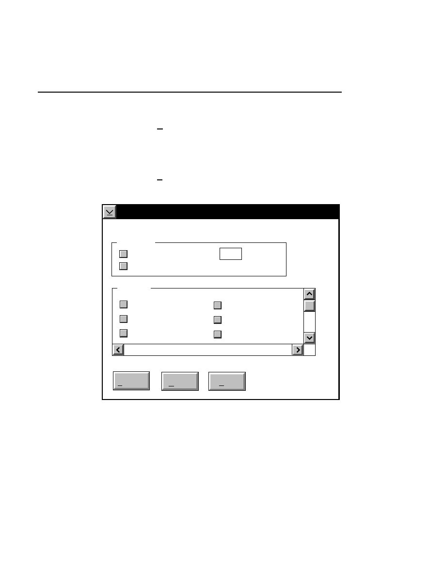
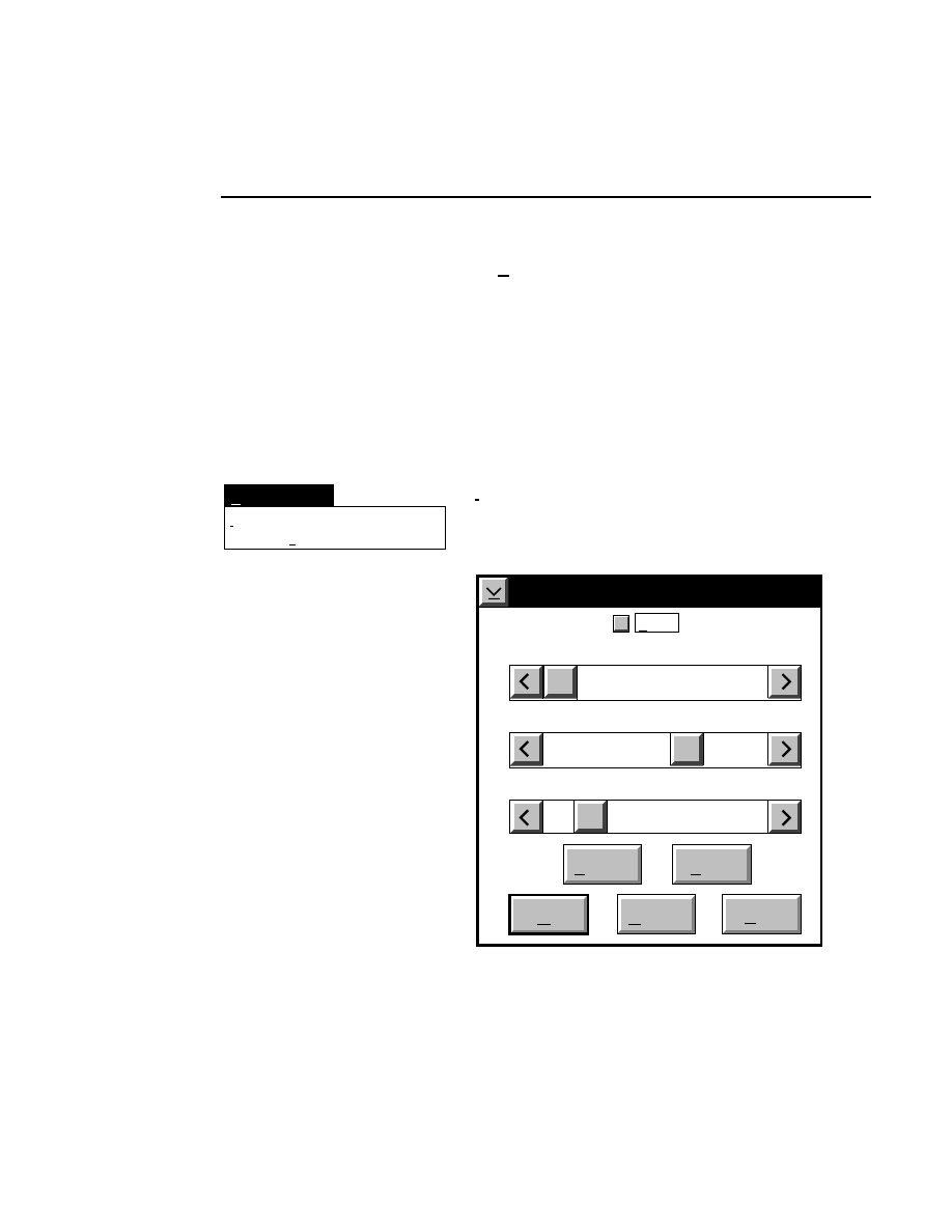
Log list...
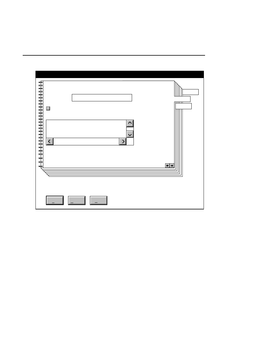
Opens the Parameters Log List box:
Scanner Control
Help
Parameters Log List
Default
Reset
Frames
Signal Filter
Scan Status
✔
✔
✔
✔
✔
✔
Date
Time
HVPS Status
Auto log
Log list
At interval (minutes): 20
At parameter change.
All of the operating parameters can be recorded in the Log
Notepad at a user-defined time interval, by selecting them in
the Parameters Log List box.

Section 2
2-8
Scanner Control Window - Parameters Menu
When the Parameters Log List box is opened, several
operating parameter check boxes will be selected. These are
the default parameters that will automatically be recorded in
the Log Notepad. Use the scroll bars to select additional
parameters to be recorded, or deselect ones that you do not
want to record.
Under “Auto log” there are two options:
At interval (minutes):
- enter the time interval at which to
record the selected operating parameters to the Log Notepad,
from 0 to 60 minutes. Deselect this box, or enter 0 if you do
not want to record any parameters. The default value is
derived from the active configuration file.
At parameter change
- if checked, the selected parameters
will be recorded to the Log Notepad each time a field is edited
and the parameters sent to the Sequencer. This is in addition
to recording at the interval set above (if selected).
In the
Parameters Log List
box:
Press
to...
Default
Reset
Load values for the Log List from the
active configuration file.
Reset the check boxes to the state they
were in when the dialog box was
opened.
Scanner Control Window
Scanner Control Window - Copy Menu
2-9
Copy Menu
Selected
All
Copy
Log list
Ctrl+C
Log list
Ctrl + C
Copies the current values of the parameters selected in the
Parameters Log List to the system clipboard, where they can
be pasted into other applications (e.g., the Image Notepad).
Selected
Copies the current values of the parameters selected in the
Scanner Control window to the system clipboard, where they
can be pasted into other applications. Parameters are selected
in the Scanner Control window by clicking the pointer on the
desired parameter. Click and drag the pointer up or down to
select multiple parameters.
All
Copies the current values of all operating parameters to the
system clipboard, where they can be pasted into other
applications.
Section 2
2-10
Scanner Control Window - Options Menu
Options Menu
Cross Section...
Options
Ctrl+S
Focus...
Ctrl+F
Focus...
Ctrl + F
Opens the Focus window, where you can manually or auto-
matically focus the laser microscope assembly in the center of
the gel. NOTE: The Focus routine cannot be initiated if the
'Scan Status' is ON. Turn the 'Scan Status' radio button in the
Scanner Control window OFF and press Enter before focusing.
The Auto gain routine is performed in conjunction with the
focus routine, to ensure that detector sensitivity is set properly.
Channel 700 is the default channel for which the focus routine
will be run; the channel is displayed in the Focus window title
bar. Although we do not recommend it, the Focus channel can
be changed using the 'Channel' pull-down list.
Scanner Control Window
Scanner Control Window - Options Menu
2-11
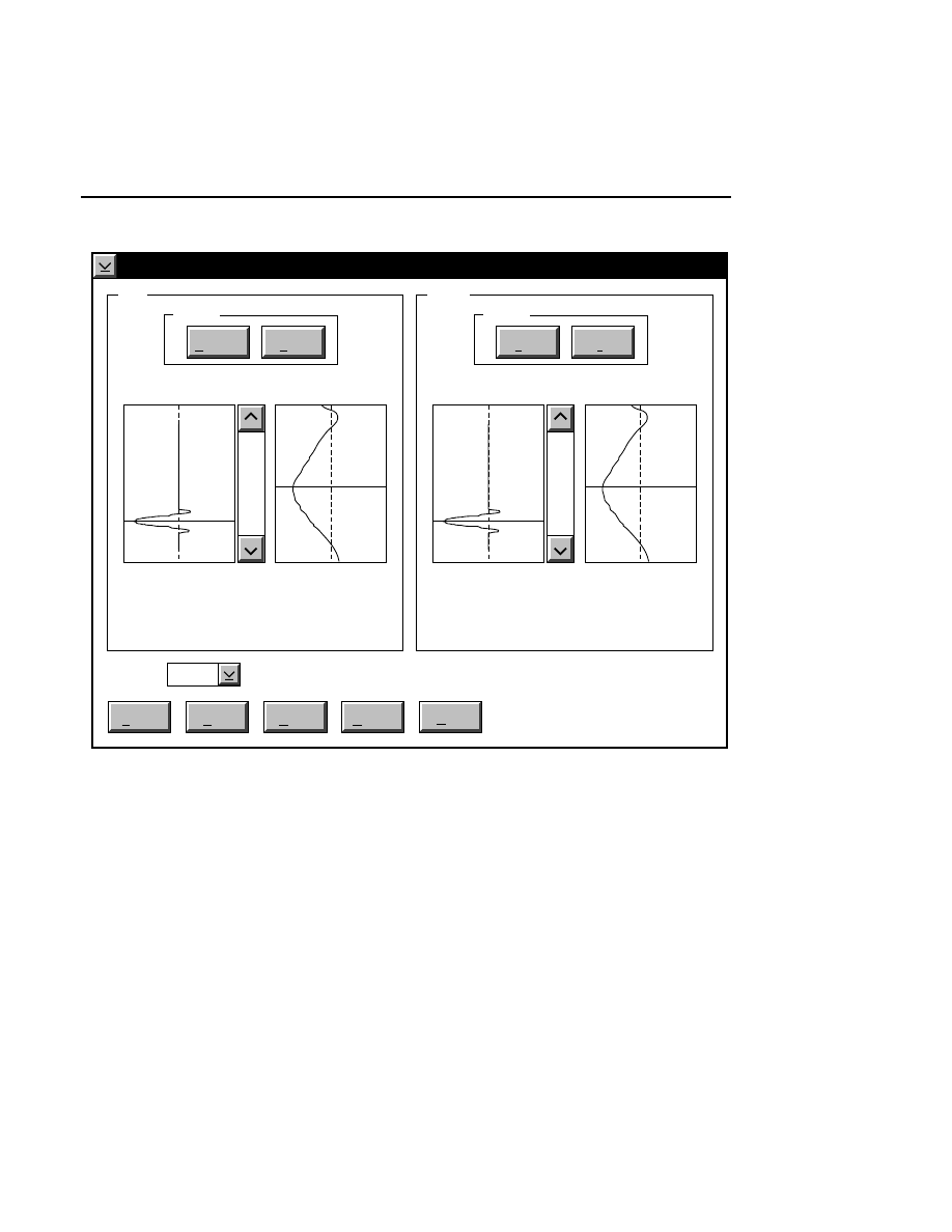
Focus - Channel 700
Reset
Help
Done
Left
Profile
Coarse
Fine
REAR
Cursor: 1899
Channel: 700
FRONT
Right
Profile
Coarse
Fine
REAR
Cursor: 1892
FRONT
Background Average:
Background Noise:
Background Average:
Background Noise:
Auto
Move
24.9
1.9
26.2
1.0
When to Focus
The laser/microscope should be focused before new image
files are collected. Both the Focus and the Auto Gain settings
affect the quality of the image during data collection. A
recommended procedure is to set the detector sensitivity using
the Auto Gain function in the Options menu, then do an Auto
Focus, and repeat the Auto Gain function to reset the detector
sensitivity for the new microscope focus position.

Section 2
2-12
Scanner Control Window - Options Menu
What Focus Does
In order to compensate for different gel plates and gel
thicknesses, the sequencer's laser/microscope stage has an
independent focusing stage. The focusing stage is independent
of the translation stage that moves the microscope back and
forth across the gel. This allows different focusing positions
on the left and right sides of the gel, which compensates for
gels that may not be perfectly parallel with the focusing plane
of the microscope.
Rear
Front
Rear Glass
Gel
Front Glass
Relative Fluorescence Signal
Microscope Position
During focusing, fluorescence is detected while the
laser/microscope is moved forward from the rear of the
instrument. The point of focus for the microscope is slowly
moved from the window in the heater plate, through the rear
gel plate, into the gel, and finally into the front plate. There is
no fluorescence until the point of focus is in the rear gel plate.
Also, the gel has much lower fluorescence than the two gel
plates, so a typical fluorescence profile shows a flat line at zero
until the microscope moves into the rear gel plate. At this
point the curve moves upward and stays high while the focal
point is in the rear plate. When the point of focus is in the gel
the fluorescence curve dips down and then comes back up
when the laser/microscope is focused in the front gel plate.
The point of focus (the red line) should be where the average
background fluorescence is the lowest. If the red line is not
properly positioned, use the Move button (below) to reposition
the microscope.
The laser/microscope has both coarse and fine profiling
modes. During a coarse profile the microscope is moved
rapidly through its full range of focus movement, starting at
the window in the heater plate and ending at the front plate.
The fine profile has a narrower range of movement that is
centered around the focus point. Pressing the
Auto
button is
similar to doing a coarse and fine profile at each side of the
apparatus.

Scanner Control Window
Scanner Control Window - Options Menu
2-13
Autofocusing
Pressing the
Auto
button initiates an auto focus that results in
four curves being displayed in the in the profile windows. On
the left side is a fluorescence profile of the left side of the gel
and a magnified view of the same profile. Two similar
profiles are shown for the right side of the gel. The left side of
each profile window represents the lower limit of the detector
range and the right side is the upper limit. The top of the
profile window represents the limit of the microscope's
focusing range at the rear of the instrument, and the bottom of
the window represents the focusing limit at the front of the
instrument.
After an auto focus the curve in the profile window should dip
to the left with the red focus cursor in the center of the dip. If
the curve is truncated on the left side of the profile window,
the detector gain and offset should be adjusted using the Auto
Gain routine. The degree to which the curve dips to the left is
a function of the Average background parameter set in the
Auto Gain dialog. For example, if the average background is
set at 25, the bottom of the dip in the profile window should be
25% of the way between the left and right sides of the profile
window.
Manual Focusing
Manual focusing is generally not needed unless you wish to
see a profile of the gel sandwich. To start a manual focus,
press the Coarse profile button for either the left or right side
of the gel. Unlike auto focus, the left and right sides are
profiled separately. The coarse profile moves the microscope
over the entire focusing range and collects fluorescence data
with low resolution. This makes the magnified curve in the
profile window look jagged. Doing a fine profile will move
the microscope over a narrower range centered around the
focus position as defined by the cursor. More fluorescence

Section 2
2-14
Scanner Control Window - Options Menu
data will be collected, resulting in a smoother curve in the
magnified profile window. Before repositioning the red
microscope position cursor you should perform both the
coarse and fine profile routines. If the red microscope position
cursor is not in the center of the gel, it can be moved as
described below under the Move button.
Move Button
The red line is a cursor that indicates the physical position of
the microscope. The arrows and slider on the profile windows
can be used to move the focus position of the microscope in
order to better center the focus position in the gel. After using
the arrows, the green line indicates where the red microscope
position marker and the microscope focus position will move
to when the MOVE button is pressed. The microscope is not
physically moved to the new focus position until the MOVE
button is pressed.
Reset Button
The Reset button changes the microscope focus position back
to where it was before the green "move to" line was defined in
the profile window.
During scanning (not profiling) it is occasionally useful to see
the background noise and average for the left and right sides of
the gel. This is accomplished by double-clicking on the right
or left sides of the dialog box while focusing. When you
double-click in the dialog, the microscope will move to that
side and will calculate the average background and back-
ground noise. These values are displayed in the focus window
as scanning progresses.
Scanner Control Window
Scanner Control Window - Options Menu
2-15
Cross Section...
Options
Ctrl+S
Focus...
Ctrl+F
Cross Section...
Ctrl + S
The cross section function is a diagnostic tool that can be used
to determine the position of the DNA fragments in the gel,
relative to the glass plates. This can be useful for determining
if the laser/microscope is focused onto the position in the gel
where the DNA fragments are located. In some instances,
DNA fragments can migrate near the glass plates, in which
case the focus position in the center of the gel may not be
optimal for detecting the fluorescence of the dye-labeled DNA
fragments. In other instances, the gel may acquire a slight
convex or concave shape, so that the point of focus on the left
and right sides of the gel may be different than at the middle of
the gel. Cross sectioning the gel can help determine if any of
these anomalies are occurring.
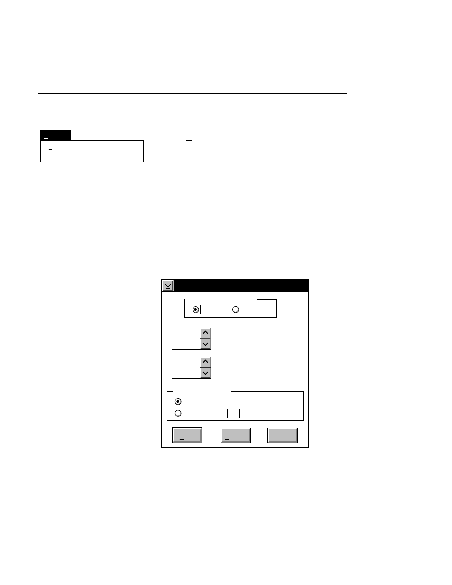
Cross Section
Cancel
Start
Help
High Voltage Status
Off
On
Do Cross Section
Now
5 Frames
After every:
1
15
Scan lines per focus motor
move
Width of cross section
(X0.01mm)

Section 2
2-16
Scanner Control Window - Options Menu
The High Voltage Status radio buttons determine whether or
not the high voltage power supply will be turned On or Off
when performing the cross section. In most cases the power
supply will be Off (the Default), to prevent active movement
of the DNA fragments during the procedure. The 'Scan Status'
button must be ON for the Cross Section to perform properly.
The 'Scan lines per focus motor move' determines how many
lines of image data will be taken at each focus motor position,
designated in the 'Width of cross section' box. The focus
motor is a stepper motor that moves the laser/microscope
assembly perpendicular to the gel, in increments of 0.01 mm.
The number of "steps" is designated in the 'Width of cross
section' box. The width is determined by how much of the gel
you want to cross section, and is centered around the focus
position of the laser/microscope. For example, with a 0.4 mm
gel, it would require 40 "steps" around the focus position to
completely cross section the gel. The maximum value for the
cross section width is 100 (1 mm), and the maximum number
of scan lines per focus motor move is 16. The total number of
scan lines collected during the cross section must not exceed 1
frame of data (512 scan lines), however.
When
Start
is pressed, the laser/microscope assembly moves
backwards (relative to the glass plates) until it reaches the
starting point. Scanning will begin, and the laser/microscope
will move forward in 0.01 mm increments while scanning the
designated number of steps.
The 'Do Cross Section' radio buttons determine when the cross
sectioning function will begin. Select
Now
to perform the
cross section immediately. To do multiple cross sections after
a given number of frames, enter the frame number and click
the 'After every X frames' radio button. For example, if '5' is
entered, the cross section will be performed after frame
numbers 5, 10, 15, etc.

Image Window
3-1
Image Window
Overview
If the Data Collection project was initialized to collect image
data on both channels, two Image windows will appear. Each
window has the same four menus described below.
In the Image window, image data from the sequencer are
displayed in an autoradiogram-like format (i.e., as black bands
on a white background, or white bands on a black back-
ground). If you are collecting data on both channels, two
image windows will be displayed.
When a new file is created in Data Collection, the Image
window(s) will initially be empty, until gel electrophoresis has
been initiated.
Changing the Image Window Display
The Image Window display can be changed in either of two
ways; the title bar information can be changed using the
Title
Bar
menu item in the Options menu, and the current values of
signal gain, signal offset, and frames collected for each
channel can be toggled on and off using the
Show gain/offset
menu item in the View menu.
The values at the bottom of the Image window can be edited
and sent to the sequencer for implementation by pressing
Section 3
3-2
Image Window
Enter
, or by choosing the
Send gain/offset
menu item in the
View menu.
Goto
Enhancement
View
Image: 2,700 nm,700nm.tif - NO DATA
Options
Frames
Gain
Offset
0:0
800
250
25
Image Window
Image Window - Goto Menu
3-3
Goto Menu
Frame...
1/4 page up
Goto
Tab
Tab
1/4 page down
Ctrl + A
Shift+PgUp
Shift+PgDn
Tab
Tab
Scrolls the image to the tab marker, which is set with the
Set
tab
function in the View menu.
Frame...
Ctrl + A
Scrolls the image to the frame number specified in the Goto
Frame dialog box. A frame consists of 512 rows of image
data.
Type the number of the frame to which the image will be
scrolled, or use the scroll arrows to change the number. Click
OK
to scroll the image, or
Cancel
to close the dialog box
without scrolling the image.
1/4 page up
Shift + PgUp
Moves the image 1/4 of a frame up.
1/4 page down
Shift + PgDn
Moves the image 1/4 of a frame down.
NOTE: The Home, End, Page Up, and Page Down keys
also function in the Image window as follows: Home -
image moves to beginning of file; End - image moves to
end of file; Page Up - image moves 3/4 of a frame up;
Page Down - image moves 3/4 of a frame down.
Section 3
3-4
Image Window - View Menu
View Menu
Set tab...
Clear tab
View
✓
Auto scroll
Ctrl+C
Ctrl+V
Enter
White on Black
Delete image...
Show gain/offset
Send gain/offset
✓
Black on White
Auto scroll
Ctrl + C
Toggles the Auto scroll function ON/OFF. If enabled, the
window will display the last 512 lines of image data, and the
image will scroll in the window as new scan lines are added
during electrophoresis. If Auto scroll is disabled, the image
will not scroll in the window during electrophoresis. A ✓
(check mark) before the menu item indicates that the Auto
scroll function is enabled.
Other operations that change the displayed image, including
resizing the image window and scrolling the window vertically
will also cause the Auto scroll function to be disabled.
Set tab...
The tab is a visual marker that can serve as a reference point in
Image Analysis. For example, by setting the tab at the primer
front during Data Collection, the Goto Tab function in Image
Analysis can be used to quickly scroll the image to the primer
front to begin sequencing.
Prior to setting the tab, scroll the image to the frame which
you want to contain the tab marker. When Set tab is selected,
a horizontal line appears across the image. Use the mouse to
move the tab marker up or down to the desired location, and
click the mouse button once to set the tab at that location.
Clear tab
Removes the tab marker from the Image window.
Image Window
Image Window - View Menu
3-5
White on Black/Black on White
Ctrl + Y
Toggles the displayed image between black bands on a white
background and white bands on a black background. This
does not affect the data being stored in the image file.
Delete image...
Deletes all image data present in the image window. This
function can be useful for deleting meaningless image data
collected during pre-electrophoresis, or before bands begin to
appear in the Image window.
CAUTION!
This function will permanently delete all
image data. Do not perform this function after meaning-
ful image data appear in the image window.
Make sure that the Autoscroll function in the Image Window
(View menu) is ON before using the Delete image function, to
confirm that bands have not started past the detector.
Set tab...
Clear tab
View
✓
Auto scroll
Ctrl+C
Ctrl+V
Enter
White on Black
Delete image...
Show gain/offset
Send gain/offset
✓
Black on White
Show gain/offset
Toggles the gain, offset, and frames collected values at the
bottom of the Image Window ON/OFF. If enabled, the
window will display the number of frames of data collected,
and the current values of the signal gain and offset for that
channel.
These values can be edited if desired, and sent to the sequencer
by pressing
Enter
, or by choosing the
Send gain/offset
menu
item (below).
Section 3
3-6
Image Window - Enhancement Menu
Send gain/offset
Enter
Sends the currently displayed values of signal gain and offset
to the sequencer for implementation. The signal gain and
offset values are set independently for each channel; when you
press Enter, the values sent to the sequencer will be those
present in the active image window.
Enhancement Menu
Enhancement
Intensity adjustment...
Image size...
Ctrl+I
Ctrl+Z
Intensity adjustment
Ctrl + I
Selecting Intensity adjustment from the Enhancement Menu
opens the Intensity Adjustment dialog box:
Intensity Adjustment
Brightness 60
Show
Contrast 20
Cancel
OK
Help
Default
Reset
Sensitivity 0
✔

Image Window
Image Window - Enhancement Menu
3-7
The Intensity Adjustment dialog lets you change how the
image is displayed in the image window using the sensitivity,
brightness and contrast slider bars. When the sliders are
moved, the changes are automatically implemented in the
image window, allowing you to adjust the image intensity
interactively.
Changes to the image sensitivity (16-bit mode only),
brightness and contrast affect only the appearance of the
image and not how the data are collected or stored.
The
Sensitivity
slider bar changes the lookup table that is
applied to the image when data are collected in 16-bit mode.
Values from 0 to 7 can be applied to the data; experiment by
moving the slider bar until the image appears as desired. This
slider bar will be greyed out when data are collected in 8-bit
mode.
The
Brightness
slider bar changes the value of the average
background intensity. Moving the slider to the left (or clicking
the left arrow button) reduces the background intensity. As
the brightness value displayed above the slider bar approaches
zero, the average background gets darker (when viewing white
bands on a black background). Moving the slider to the right
increases the average background intensity, making the image
background appear lighter as the brightness value approaches
100.
The
Contrast
slider bar changes the intensity of the
background noise. Moving the slider to the left (or clicking
the left arrow button) reduces the background noise of the
image. As the contrast value displayed above the slider bar
approaches zero, the background of the image will be less
grainy and more uniform. The bands will also be less distinct.
Section 3
3-8
Image Window - Enhancement Menu
Moving the slider to the right increases the background noise
of the image, making the background more grainy and the
bands somewhat easier to distinguish.
NOTE: The above effects are reversed when the image is
displayed with black bands on a white background.
The
Show
check box toggles between an altered intensity
setting and the default intensity setting when checked and
unchecked. The Show check box is automatically checked
when either of the brightness or contrast sliders are moved.
The slider positions do not change when the show check box is
deselected, but the image intensity reverts back to the default
values.
Enhancement
Intensity adjustment...
Image size...
Ctrl+I
Ctrl+Z
Image Size...
Ctrl + Z
The image can be enlarged or reduced, either proportionately
or non-proportionately. Sizing the image does not change the
image data; it only affects the way that the image is displayed.
Image Size
Cancel
Help
OK
Horizontal Multiplier (%)
Default
100 Vertical Multiplier (%)
100

Image Window
Image Window - Enhancement Menu
3-9
The image can be resized in either of two ways; with the
dialog box or with the mouse.
Using the Image Size Dialog Box
To specify the scale, type the appropriate percentages into the
Horizontal and Vertical multiplier fields. The multiplier range
is 10 to 1000.
Using the Mouse
The image can be scaled at any time without using the Image
Size dialog box by dragging the image window border(s)
while holding down the right mouse button. If you double the
size of the window (both horizontally and vertically), and then
open the Image size dialog, you will find that the Horizontal
and Vertical multiplier fields read about 200%. Similarly, if
you halve the size of the window, the multiplier fields will
read about 50%.
The image can be scaled several times in succession. For
example, let's say that you want to scale the image to about
200% of the original size in the horizontal dimension only.
Follow these steps:
●
Drag the right border of the window to the right, while
holding the right mouse button, until you reach the edge
of the screen.
●
Now drag the same border to the left while holding the
left mouse button, so that the window size is reduced to
about half of the current size. Sizing the window with the
left mouse button affects only the window size, not the
image size.
●
Enlarge the window again while holding the right mouse
button. If you open the Image Size dialog box, you will
notice that only the horizontal multiplier has changed.

Section 3
3-10
Image Window - Enhancement Menu
This process can be repeated several times, within the
defined size limits, to enlarge or reduce the image.
The image window can be enlarged by clicking on the
maximize button in the upper righthand corner of the window,
or by double-clicking anywhere on the window's title bar.
Clicking the maximize button or double-clicking the title bar
will return the window to its previous size.
In the
Image Size
dialog box:
Press
to...
Default
Reset image size to the default size
(100% vertical and horizontal).
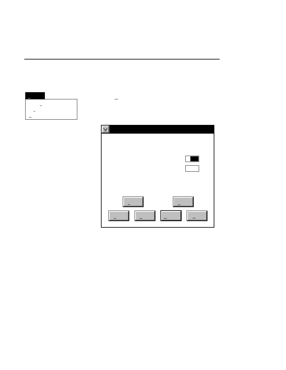
Image Window
Image Window - Options Menu
3-11
Options Menu
Auto gain...
Title bar...
Remarks...
Options
Ctrl+G
Auto gain...
Ctrl + G
Note that the auto gain function is present in both image
windows, and is performed independently for each channel on
which data are collected.
Auto Gain
Done
Help
Signal gain:
Signal offset:
Background average (0-85):
Background noise (0-50):
Estimated completion time:
Elapsed time:
Defaults
Cancel
2.5
200
100
00:30
Reset
Auto
1
When to Set the Gain
The auto gain calculation should be performed before each
new image file is collected. Both the auto gain setting and the
focus of the laser microscope affect the quality of the image.
A recommended procedure is to set the detector sensitivity
using the Auto Gain calculation, do an Auto Focus, then repeat
the Auto Gain calculation to reset the detector sensitivity for
the new microscope focus position. The second Auto Gain

Section 3
3-12
Image Window - Options Menu
calculation is performed because the background fluorescence
may be different at the new microscope focus position.
What Auto Gain Does
The Auto Gain routine calculates the required signal gain and
offset for the fluorescence detector that will produce an image
having the average background and noise specified by the
user. The background fluorescence tends to vary, producing a
slightly different average background intensity from run to
run. By specifying the desired average background and
changing the detector gain and offset to achieve that back-
ground, images can be made to have a uniform appearance
from run to run, even though the glass-gel sandwiches may be
slightly variable.
How to Choose Background Values
Default values for Background Average and Noise are defined
in configuration files. The default configuration file
(
DEFAULT.COL
) contains values that experience has shown
to produce good results for a typical gel. You may want to
change the appearance of the background to suit your personal
preferences or to enhance some particular aspect of the image
you are collecting. The default values can be loaded into the
background edit fields at any time by pressing the Defaults
button.
Background Average can be set from 0 through 85. As the
background average gets closer to 0, the image background
gets darker (when viewing white bands on a black
background). Setting the average background intensity closer
to 85 will make the background lighter.
Background Noise can be set from 0 through 50. Noise values
closer to 0 will make the background of the image less grainy
and more uniform. This also results in the bands being less

Image Window
Image Window - Options Menu
3-13
distinct. Noise values closer to 50 make the image
background more grainy, but the bands are brighter and may
run together.
Starting the Auto Gain Calculation
Pressing the
Auto
button starts the auto gain calculation. A
time estimate for completion and the elapsed time are shown
below the background noise edit field. The background
average and noise in the edit fields are target values for the
calculation, so the real values may vary slightly. After the
calculation is complete, the actual background average and
noise that result from the calculated signal gain and offset are
shown to the left of the background average and noise edit
fields. The gain calculation will not always achieve exactly
the same results in successive calculations.
As soon as the calculation is complete, you will notice that the
actual signal gain and offset of the detector (as shown at the
bottom of each image window) have changed to the newly
calculated values. The set values in the image window will
not change unless the
Done
button is pressed.
Section 3
3-14
Image Window - Options Menu
Auto gain...
Title bar...
Remarks...
Options
Ctrl+G
Title bar...
Allows you to change the title bar information that is displayed
in the image window. You can choose to display the channel
number, channel name, and file name, or all of the above
(combined).
Image title style
Cancel
Combined
Channel number
Channel name
File name
Help
OK
Remarks...
Opens the Remarks text editor box. The remarks shown
initially are those entered in the New dialog box when each
image file was created. This menu item is not activated until a
new Image file is created.
The Remarks can be edited as desired. Enter up to 500
characters in the text box. Selected text can be copied to the
clipboard by pressing
Copy
, where it can be inserted into other
applications (e.g., the Image Notepad).

Configuration Notebook
4-1
Configuration
Notebook
General Overview
The Configuration notebook window represents a file that can
be saved with a unique set of preferences for different
sequencing protocols or individual users.
Most default operating parameters in the Scanner Control
window, as well as the Image Display Style and Log Notepad
parameters can be defined in the Configuration notebook.
They can also be applied as a group to the Scanner Control
window. This can be very useful, if, for example, a user has a
number of different electrophoresis protocols (i.e., short gels,
thin gels, etc.). The user can open the configuration file for a
given protocol and apply the parameters to the program
globally, rather than changing each parameter individually.
A default configuration file (
DEFAULT.COL
)
is in the
DNA4200 directory. This file contains operating parameters
which LI-COR has determined to be suitable for the gel
electrophoresis procedures described in the DNA Sequencing
Manual. This configuration file can be modified as desired
and renamed as a new file, or saved as the new
DEFAULT.COL
configuration file.

Section 4
4-2
Configuration Notebook
There are a number of other configuration files in the
DNA4200 directory that are specific for protocols described in
the various Sequencing Bulletins in the DNA Sequencing
Manual.
Note that the Data Collection Configuration notebook can be
run as a separate application, as well. This can be useful for
modifying or creating configuration files without opening the
Data Collection program. See the description later in this
section at Creating a Configuration Program Object.
Cfg
Configuration
When Data Collection is opened, the Configuration notebook
appears as an icon. Double-click on the icon to open the
Configuration notebook.
The Configuration notebook title bar will display the filename
of the configuration file. The
DEFAULT.COL
configuration
file is automatically opened each time the Data Collection
program is started.
Click on any of the notebook tabs to open a page related to
that tab. You can also click on the right or left arrow buttons
in the lower righthand corner of each page to move forward or
backward through the notebook pages.
The main Configuration notebook page contains an Open,
Save, Save as, and Save as Default button. In addition, each
individual page contains a Default, Reset, and Help button.
Configuration Notebook
Configuration Notebook
4-3
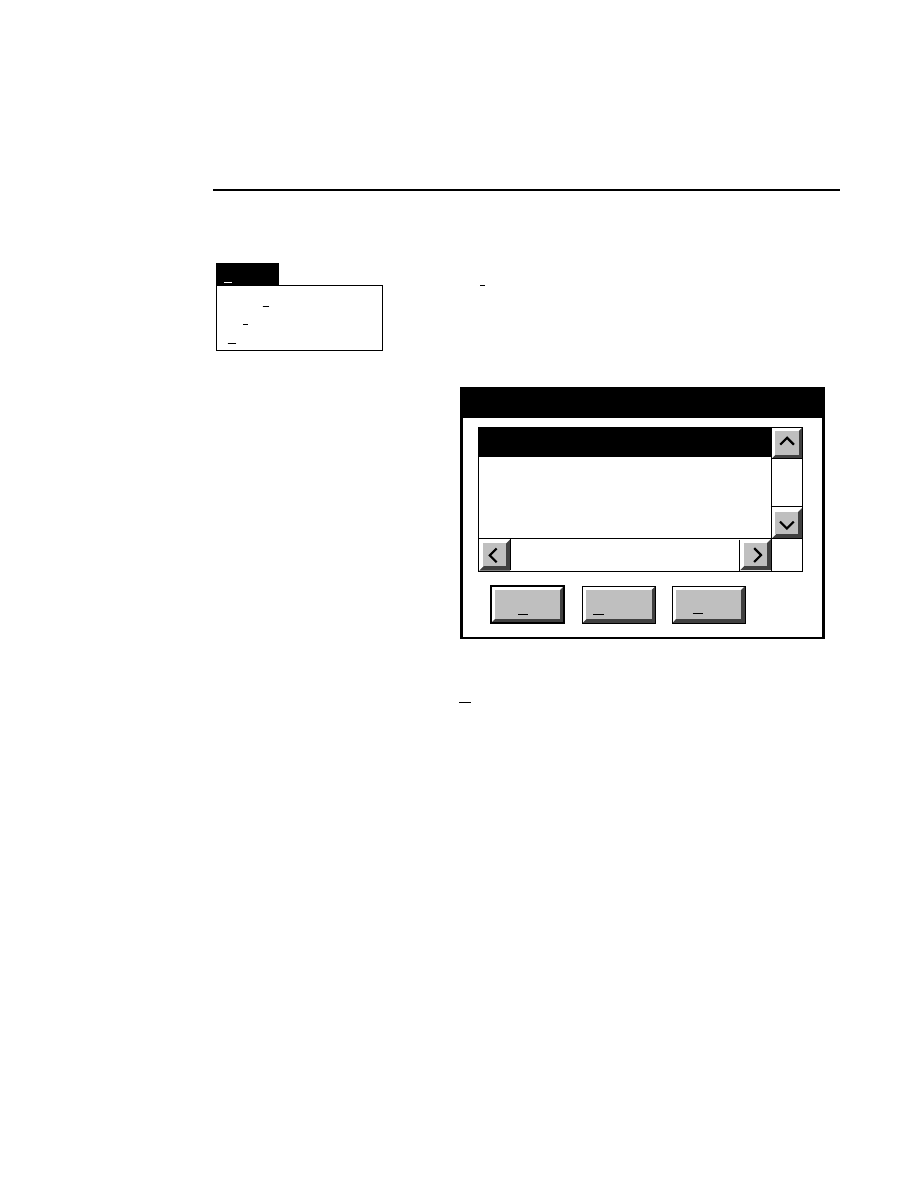
Open
Loads a configuration file into the Configuration window.
Selecting
Open
brings up the Open dialog box:
Configuration - Open
Cancel
OK
Files:
25CM_16.col
25CM_8.col
41CM_16.col
41CM_8.col
Drives:
Directories:
..
DNA4200
File:
C:
16-bit data
8-bit data
Gel size
There are two ways to open a configuration file:
1.
Type the complete path and filename in the File text entry
field, and click
O K
. For example, typing
C:\DNA4200\TEST.COL
will open the configuration file
named
TEST.COL
, located in the DNA4200 directory of
the computer’s C drive.
2
.
Click on the desired configuration file in the Files list box
and press
OK
, or
double-click on the desired configuration
file. Use the Drives and Directories list boxes to change
directories.
Section 4
4-4
Configuration Notebook
Save
Saves the current configuration parameters to the active con-
figuration file. These changes will be sent to the Scanner
Control Window, where they can applied to the sequencer, if
desired.
Save as...
Saves the current configuration parameters to a new file,
specified in the Save as dialog box.
Configuration - Save as
Cancel
OK
Files:
25CM_16.col
25CM_8.col
41CM_16.col
41CM_8.col
Drives:
Directories:
..
DNA4200
File:
C:
Enter the complete path and name of the new configuration
file in the 'File' text entry field. Select a different directory
from the Drives and Directories list boxes if necessary.
NOTE: Entering
DEFAULT.COL
for the File name is
not allowed.

Configuration Notebook
Configuration Notebook
4-5
Save as default
Saves the current configuration parameters to the default
configuration file
DEFAULT.COL
. This function will
overwrite the existing
DEFAULT.COL
file. When selected,
the user is prompted with the Save Configuration message
box.
Select
Yes
to overwrite the
DEFAULT.COL
configuration file
or
No
to cancel the function.
Default
Resets the parameters in the current notebook page to the
default values.
Reset
Resets the parameters in the current notebook page to those
that were present when the page was opened.
Help
Opens a help window related to the current notebook page.
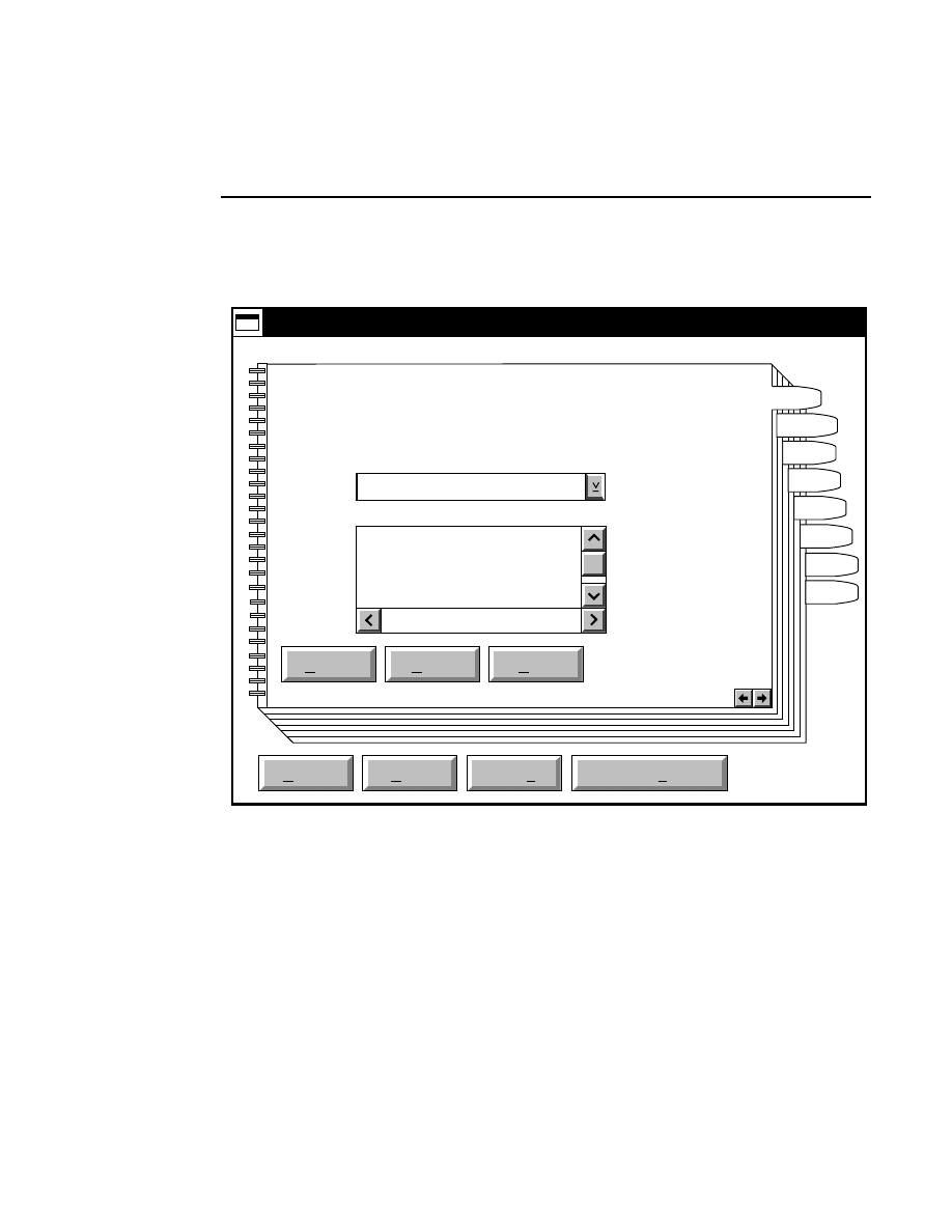
Section 4
4-6
Configuration Notebook - Path Page
Path Notebook Page
Default
Reset
Open
Save
Save as
Save as default
Help
Configuration - DEFAULT.COL
Data Directory
..
anl
col
img
Current: C:\DNA4200\data
New: C:
Drives:
C:
Directories:
HVPS
Heat
Scan
Image
Notes
Log
Exit
Path
Changes the default path to which new Image files and all
associated files will be saved. Once an Image file has been
created, changing the path in configuration has no effect on
that particular Image file. Use the Drives and/or Directories
list boxes to change the path.
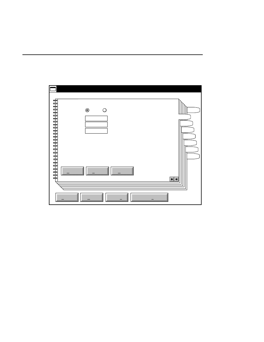
Configuration Notebook
Configuration Notebook - Power Supply Control Page
4-7
Power Supply Control Notebook Page
Default
Reset
Open
Save
Save as
Save as default
Help
Configuration - DEFAULT.COL
Power Supply Control
Initial Status: On Off
Voltage:
Current (ma):
Power (W):
HVPS
Heat
Scan
Image
Notes
Log
Exit
Path
1500
35.0
31.5
Initial Status
- select the On radio button if you want the High
Voltage Power Supply parameter to indicate ON in the
Scanner Control window when a new image is opened.
The Voltage, Current, and Power values that are initially
applied to the Scanner Control window can all be edited. See
Section 2, Scanner Control Window, for an explanation of
these parameters.
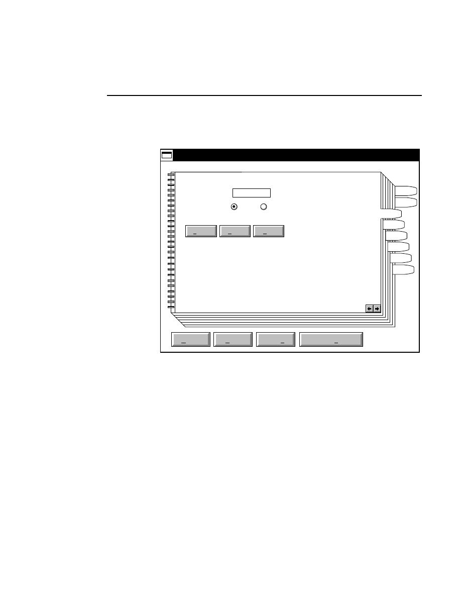
Section 4
4-8
Configuration Notebook - Heater Control Page
Heater Control Notebook Page
Default
Reset
Open
Save
Save as
Save as default
Help
Configuration - DEFAULT.COL
Heater Control
Post run status: On Off
Setpoint (degC):
HVPS
Heat
Scan
Image
Notes
Log
Exit
Path
50.0
The
Setpoint
is the temperature (in degrees C) at which the
heater plate (against which the gel apparatus rests) will be
maintained, if the power through the gel generates less heat
than this. It is possible that the power through the gel would
generate a temperature above the Setpoint. The Model 4200
has no cooling capabilities.
The
Post run status
radio buttons determine whether or not
the heater plate temperature will be maintained after the
specified number of frames of data have been collected and
data collection stops. Leaving the heater plate turned on saves
time when doing several electrophoresis runs in succession.
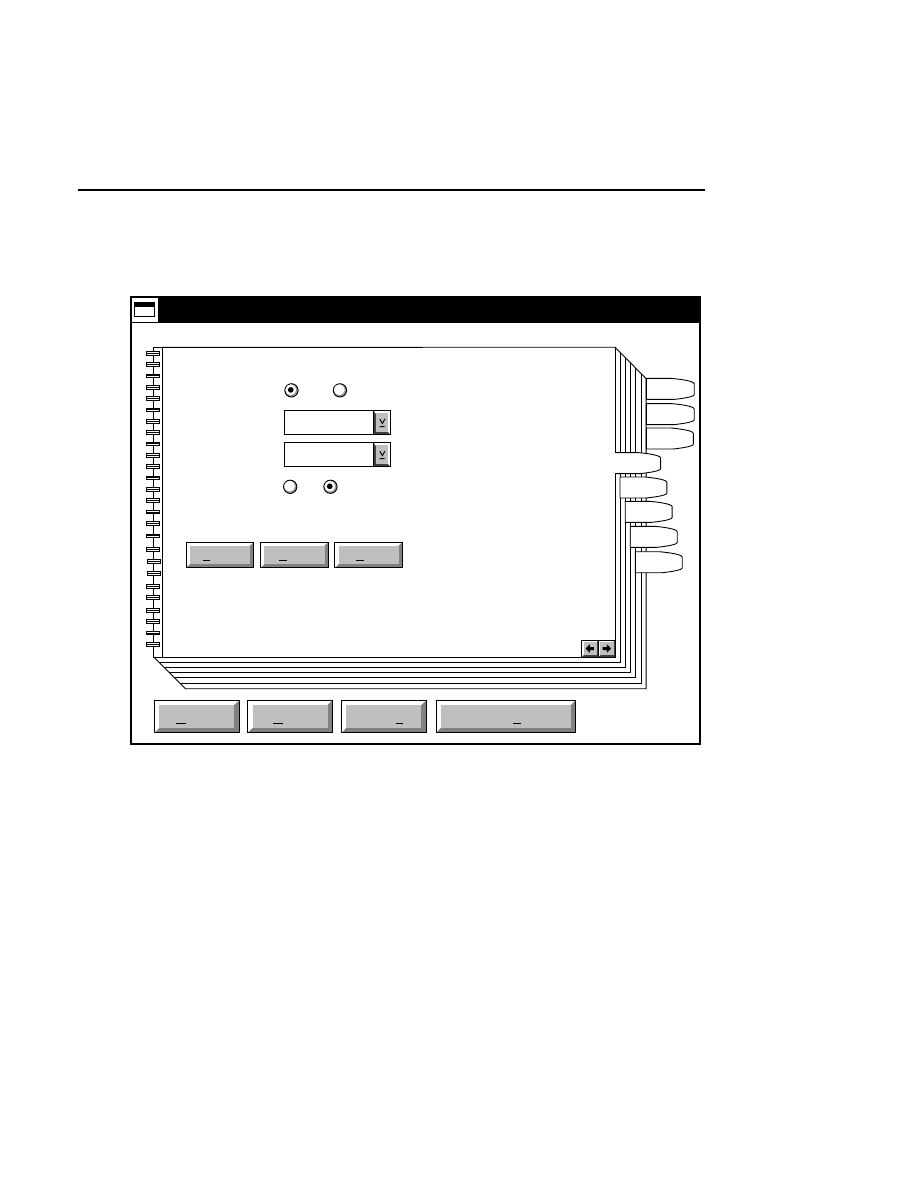
Configuration Notebook
Configuration Notebook - Scan Control Page
4-9
Scan Control Notebook Page
Default
Reset
Open
Save
Save as
Save as default
Help
Configuration - DEFAULT.COL
Scan Control
Status: On Off
Scan Speed:
HVPS
Scan
Image
Notes
Log
Exit
Path
Pixel size (bits): 8 16
3
Signal Filter:
3
Heat
The
Status
radio buttons determine whether or not the Scan
Status radio button in the Scanner Control window is set to
ON when a new image file is opened.
The
Scan Speed
determines the rate at which the scanning
laser microscope assembly moves across the gel during
electrophoresis. Changing the motor speed can be a useful
feature for high speed sequencing with the 25 cm and/or 18 cm
gel apparatus, where the rate of migration of the DNA

Section 4
4-10
Configuration Notebook - Scan Control Page
fragments is very fast. See the DNA Sequencing Manual for
protocols using the short gel apparatuses.
The
Signal Filter
field sets the default signal filter for the
configuration file being edited. The signal filter determines
the amount of electronic filtering of the image signal. Values
of 1, 2, or 3 can be selected, where 3 is the least amount of
filtering, and 1 is the most. The frequency responses for the
signal filters are as follows: 1 = 15 Hz, 2 = 61 Hz, and 3 = 122
Hz.
For normal operation, the signal filter should be set to 3. The
other settings can be used when changing the scanner motor
speed for alternate data collection protocols as explained in the
Operator's Manual. Note that changes to the signal filter are
always accompanied by automatic changes to the filter offset
(function 405 from the sequencer keypad) in order to prevent
distortion of the sequence image.
The
Pixel size (bits)
radio buttons allow you to configure
Data Collection to collect 16-bit image data instead of 8-bit
data. 16-bit images provide more digital resolution per pixel,
and make better use of the dynamic range of the detection
system. When strong and weak samples are loaded on the
same gel, 16-bit images accurately detect both samples. Note,
however, that 16-bit images require twice the amount of hard
disk space.
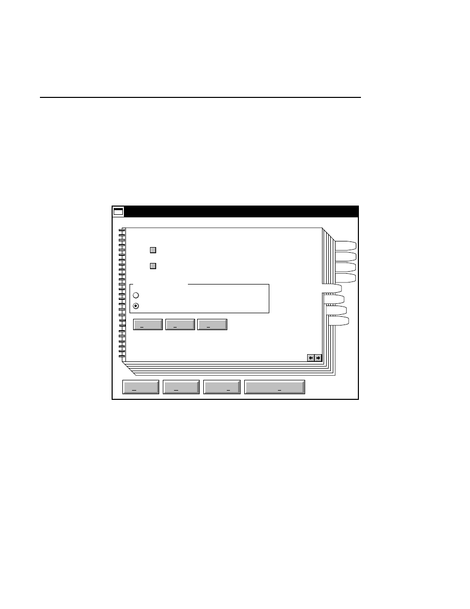
Configuration Notebook
Configuration Notebook - Image Pages
4-11
Image Notebook Pages
Page 1
The Image notebook page allows you to change the default
values for several key parameters that affect the fluorescence
detection electronics.
Default
Reset
Open
Save
Save as
Save as default
Help
Configuration - DEFAULT.COL
Image Display Style
Image
Black bands on white background
White bands on black background
HVPS
Scan
Image
Notes
Log
Exit
Path
Heat
800:
700:
Collect
✔
Collect
✔
Page 1 of 3
The 800 and 700 check boxes determine whether or not image
data are collected for one or both channels. If you are only
collecting image data on one channel, enable only the 800 or
700 check box, so that data are collected only on that channel.
The image that is collected in the Image window can be
displayed in one of two ways by selecting the appropriate
radio button; as a high contrast image with white bands on a
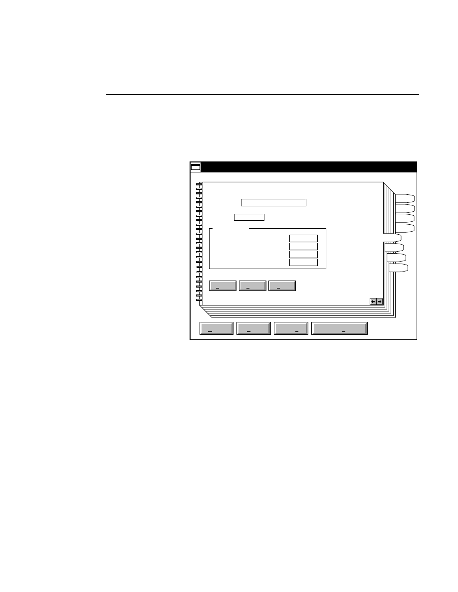
Section 4
4-12
Configuration Notebook - Image Pages
black background, or as a traditional autoradiogram-like image
with black bands on a white background.
Page 2
Default
Reset
Open
Save
Save as
Save as default
Help
Configuration - DEFAULT.COL
Signal Control
800
Gain set point (0-1000):
Offset set point (0-1000):
Background average (15-85):
Background noise (2-50):
HVPS
Scan
Image
Notes
Log
Exit
Path
Heat
File name: N1
Frames: 25
Page 2 of 3
200
100
2.5
1
The
File name
text field shows the default file name that will
be used when an image is collected on channel 800.
The
Frames
to collect determines how many frames of image
data will be scanned before automatically stopping. One
frame of image data consists of 512 vertical scan lines.
The number of bases that are visible in a frame is dependent
upon a number of factors, including the rate of migration of
the DNA fragments, the motor speed, voltage, gel concen-
tration, gel height, etc. As an example, a standard 41 cm, 6%
polyacrylamide gel run at 50
°
C, 1000V, and medium motor
speed has approximately 35-40 bases in each frame.
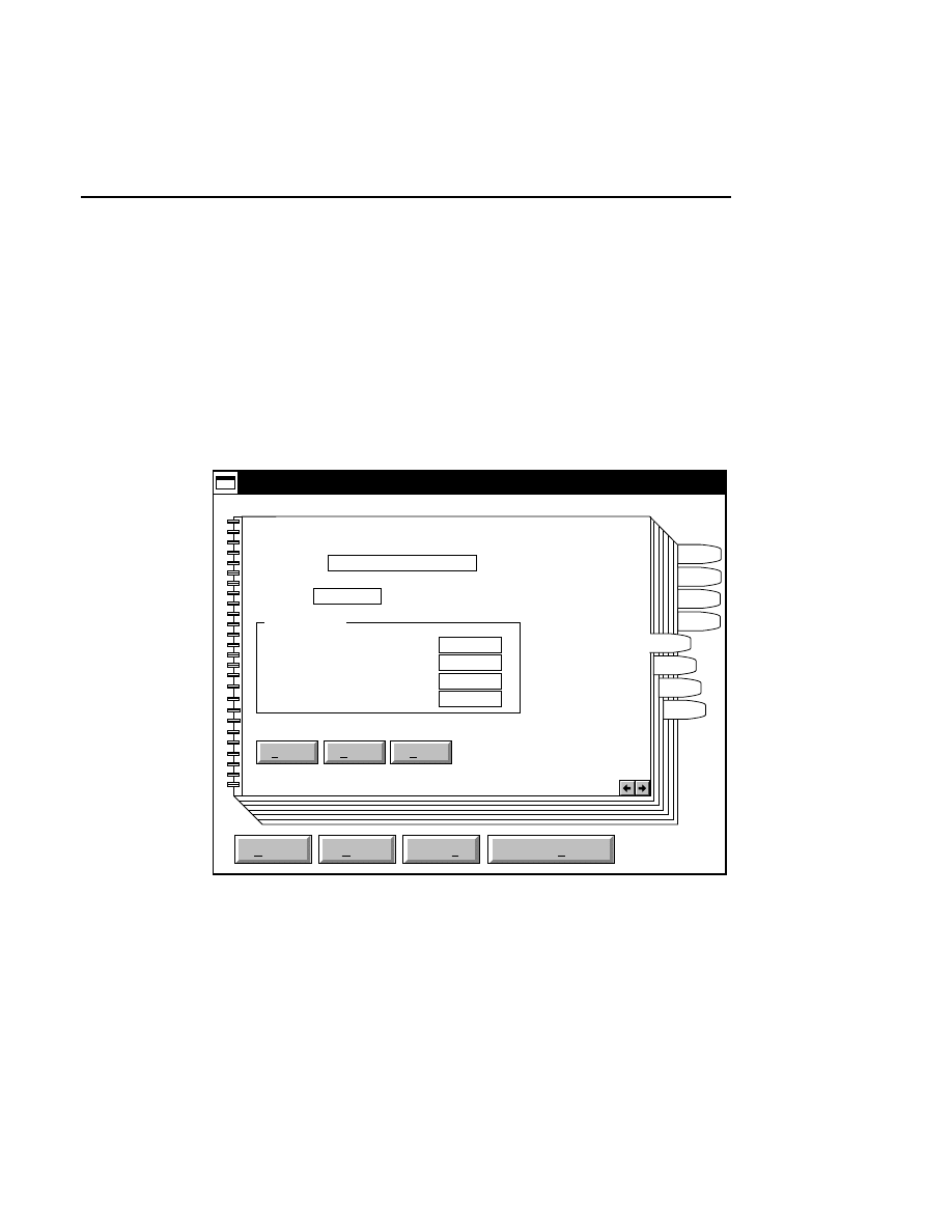
Configuration Notebook
Configuration Notebook - Image Pages
4-13
The signal background average and noise, and the signal gain
and offset fields are used to set the default values that will
appear in the Auto Gain dialog box. The Auto Gain routine
calculates the required signal gain and offset for the
fluorescence detector that will produce an image having the
average background and noise specified by the user. See
Section 3, Image Window (Auto Gain function), for a complete
description of the Auto Gain routine.
Page 3
Default
Reset
Open
Save
Save as
Save as default
Help
Configuration - DEFAULT.COL
Signal Control
700
Gain set point (0-1000):
Offset set point (0-1000):
Background average (15-85):
Background noise (2-50):
HVPS
Scan
Image
Notes
Log
Exit
Path
Heat
File name: N2
Frames: 25
Page 3 of 3
200
100
2.5
1
The
File name
text field shows the default file name that will
be used when an image is collected on channel 700. All other
parameters in this window are as described above for Page2.
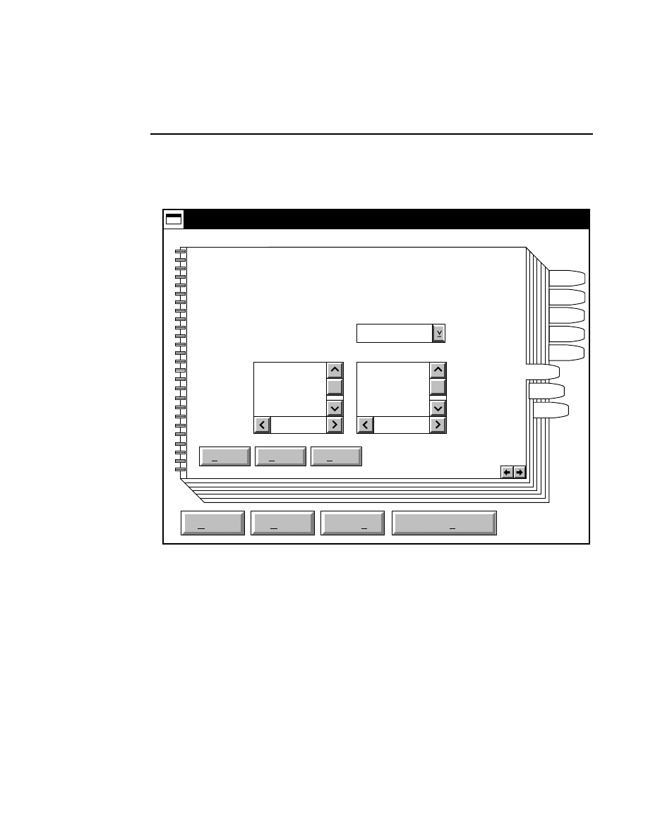
Section 4
4-14
Configuration Notebook - Notes Page
Notes Page
Default
Reset
Open
Save
Save as
Save as default
Help
Configuration - DEFAULT.COL
Image Notepad Form
HVPS
Scan
Notes
Log
Exit
Path
Heat
Image
..
anl
col
img
Current: C:\DNA4200\IMAGE.INT
New: C:\DNA4200\IMAGE.INT
Drives:
C:
Directories:
IMAGE.INT
Files:
The Image Notepad Form is a text file created with the OS/2
System Editor that can be used as a template for entering
information about the sequencing run during Data Collection.
The default form file contains header information with blank
space for entering text. This can save repeated typing of
Image Notepad entries that are common to different
sequencing operations.

Configuration Notebook
Configuration Notebook - Notes Page
4-15
The IMAGE.INT file included with the Base ImagIR software
is an example of a typical notepad form file. This file can be
modified and saved as a new form file, if desired. Notepad
form files can also be created with the OS/2 System Editor.
Save the file as Plain Text, with a .INT file extension.
The Notepad Form File in the default configuration file will
automatically be loaded into the Image Notepad when Data
Collection is opened.
To change the Notepad Form File that will be loaded, select
the desired file from the Files list box. Use the Drives and/or
Directories list boxes to change the path.
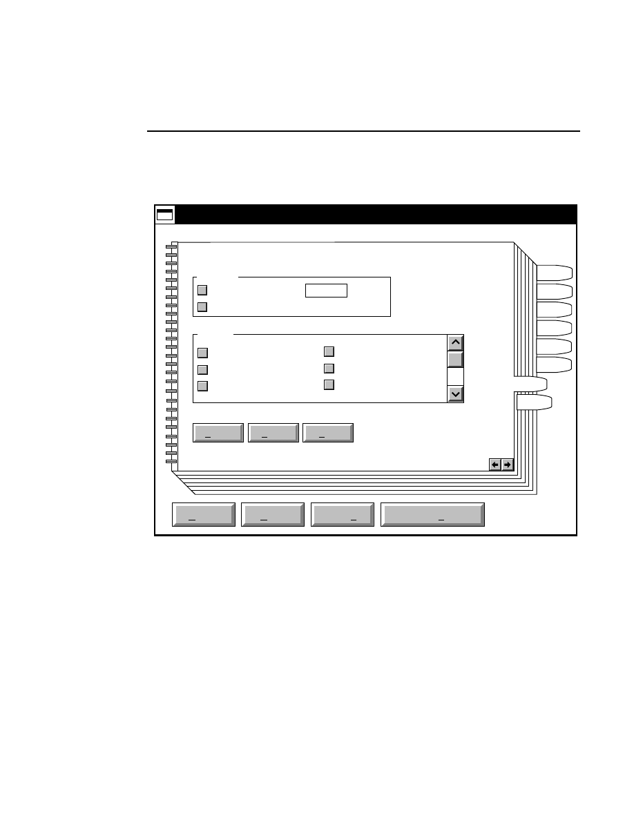
Section 4
4-16
Configuration Notebook - Parameters Log List Page
Parameters Log List Notebook Page
Default
Reset
Open
Save
Save as
Save as default
Help
Configuration - DEFAULT.COL
Parameters Log List
HVPS
Scan
Log
Exit
Path
Heat
Image
Auto log
Log list
Date
Time
HVPS Status
At interval (minutes): 20
✔
At parameter change.
✔
✔
✔
Scan Status
Motor Speed
Motor Status
✔
Notes
Some or all of the operating parameters can be recorded in the
Log Notepad at a user-defined time interval. Those selected in
the Parameters Log List page become the default log
parameters (the actual values of these log parameters can be
changed at any time during electrophoresis in the Scanner
Control window). Use the arrow keys to scroll the Log List
and select or deselect the parameters.

Configuration Notebook
Configuration Notebook - Parameters Log List Page
4-17
Under “Auto log” there are two options:
At interval (minutes):
- enter the default time interval at
which to record the operating parameters to the Log Notepad,
from 0 to 60 minutes. Deselect this box, or enter 0 if you
choose not to record any parameters.
At parameter change
- if checked, the selected parameters are
recorded to the Log Notepad each time a field is edited and the
parameters sent to the sequencer. This is in addition to
recording at the interval set above (if checked).

Section 4
4-18
Configuration Notebook - Exit Options Page
Exit Options Notebook Page
Default
Reset
Open
Save
Save as
Save as default
Help
Configuration - DEFAULT.COL
Exit dialog
HVPS: Off As is
Scan:
GPIB beep:
Temperature:
HVPS
Image
Notes
Log
Exit
Path
Heat
Off As is
Off On
Off As is
Scan
The Exit options notebook page is used to set the post-run
status of the scanning motor, high voltage power supply,
heater plate, and GPIB alert. After the specified number of
frames have been collected, the electrophoresis run will shut
down. The
Scan
,
H V P S
, and
T e m p e r a t u r e
status
buttons determine whether or not the scanning motor, high

Configuration Notebook
Configuration Notebook - Exit Options Page
4-19
voltage power supply, and heater plate will remain on after the
run is completed.
Leaving the heater plate on can be useful if you are going to
perform another electrophoresis run, as it will not be necessary
to warm the plate again before pre-electrophoresis.
When the sequencer is terminating communications with the
computer, an audible tone will sound to alert the user. If you
would like to turn off this alert, select the
GPIB beep
Off
radio button.
Message Window
5-1
Message
Window
The Message window displays system messages, including
status messages from the Model 4200, and also records Base
ImagIR commands that were performed during a session. In
normal operation, the messages in the Message window are
not needed. However, they are occasionally useful in
diagnosing system problems. The menus in the Message
window contain commands that let you save and print message
files, as well as standard text editing functions that allow you
to move Message window text to another document.
Messages
Edit
File
i
There are two menus in the Message window; the File and
Edit menus.
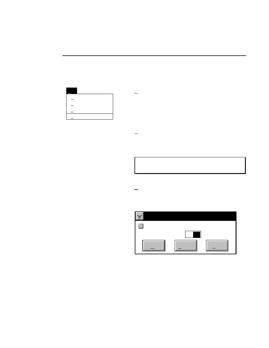
Section 5
5-2
Message Window - File Menu
File Menu
Autosave...
Save
File
New
Ctrl+P
Ctrl+S
New
Permanently erases all text in the Message window. When
New
is selected, you will be prompted with a message box
asking if you want to erase the Log file. Select
OK
to clear the
window and start a new file.
Save
Ctrl + S
Saves the system messages to a file. The file is automatically
named using the sequencer device number, followed by a
.MSG extension (i.e., DEV7.MSG).
NOTE: The message file is replaced by a new file of the
same name each time Data Collection is run.
Autosave...
Saves the Message window text at a user-selectable time
interval. The interval (in minutes) is entered in the Autosave
dialog box:
Autosave
At interval of: Minutes:
Cancel
OK
Help
✔
10
Autosave
Enter ‘0’ in the text entry field, or deselect the check box to
disable the Autosave feature.
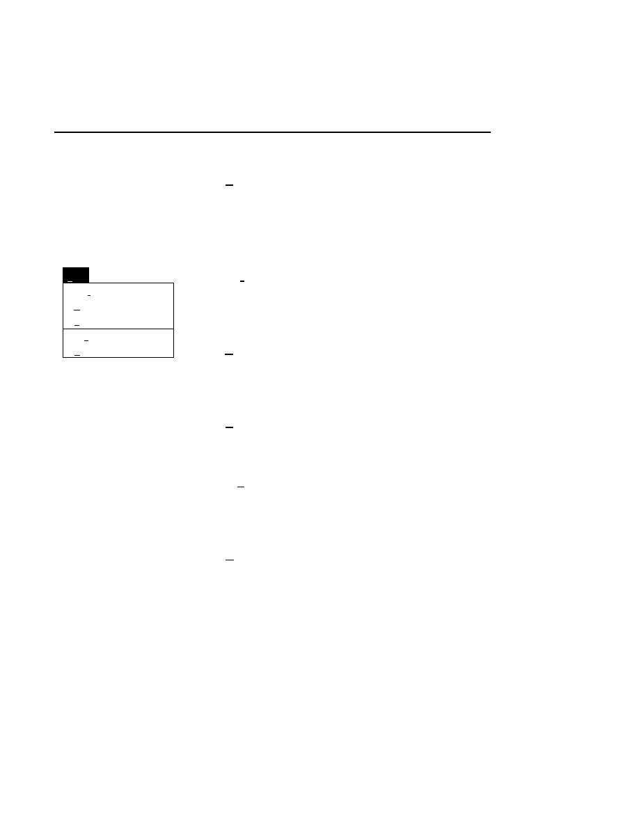
Message Window
Message Window - Edit Menu
5-3
Ctrl + P
Prints the Message window text to the system printer.
Edit Menu
Clear
Paste
Copy
Edit
Cut
Shift+Del
Ctrl+Ins
Delete
Shift+Ins
Cut
Shift + Del
Deletes selected text, and places it in the clipboard, for later
retrieval (until another selection is cut or copied).
Copy
Ctrl + Ins
Copies selected text to the clipboard, without removing it from
the Message window.
Paste
Shift + Ins
Inserts text from the clipboard at the cursor position.
Clear
Replaces selected text with spaces. The selected text is not
copied.
Delete
Removes selected text without copying it to the clipboard.
NOTE: The Delete key performs this same function.

Image Notepad
6-1
Image Notepad
Opening the Image Notepad in Data Collection
The Image Notepad is a standard text editor, similar to the Log
Notepad, with the exception that the Image Notepad does not
record any operating parameters. The Image Notepad is
typically where relevant information about the sequencing run
(i.e., name, date, gel characteristics, lane loading formats, etc.)
is recorded. This information is saved with the associated
image file, and is available for review in Image Analysis.
A useful feature of the Image Notepad is the ability to create a
notepad form file that serves as a template for entering
repetitive text information. A sample of this type of template
is included with the Base ImagIR software; the file is located
in the DNA4200 directory, and is named
IMAGE.INT
. This
file contains header information, with space available for
entering information about the sequencing operation (a portion
of this template file is shown below).
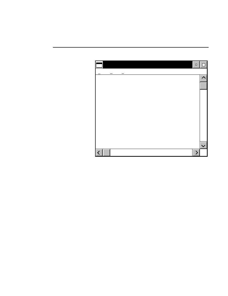
Section 6
6-2
Image Notepad
Image Notepad
Edit Options
File
Image Notepad (LI-COR Form)
[Site]
:Institution:
:Lab:
:Researcher (Initials, FML):
[EXPERIMENT]
:Image Filename:
:Date of Run:
:General Description:
When Data Collection is closed, the Image Notepad is
automatically saved with the same filename as the image file,
with a
.INT
extension.
By specifying the appropriate notepad file in the default
Configuration file, a custom notepad form file can auto-
matically be loaded into the Image Notepad each time Data
Collection is opened.
Custom notepad form files can be created using the OS/2
System Editor. Save the file with a .INT extension.
There are three menus in the Image Notepad (when opened in
Data Collection):
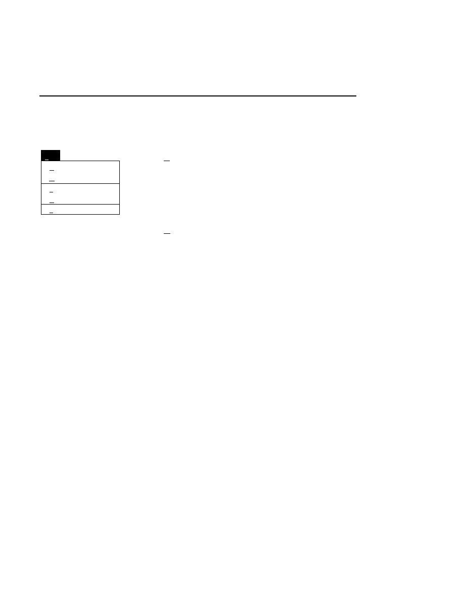
Image Notepad
Image Notepad - File Menu
6-3
File Menu
Autosave...
Save
Open...
File
New...
Ctrl+P
Ctrl+S
New...
Erases all text in the Image Notepad. You will be prompted
with a message box asking if you want to erase the notepad.
Press
OK
to clear the notepad, or
Cancel
to close the message
box without erasing the text.
Open...
Loads an existing notepad file into the Image Notepad for use
as a form file. The existing file will not be changed.
There are two ways to open a notepad file:
1.
Type in the complete path and filename in the 'File' text
entry field, and click
Open
. For example, typing
C:\DNA4200\TEST.INT would open the notepad file
named TEST.INT, located in the DNA4000 directory of
the computer’s C drive.
2
.
Click on the desired notepad file in the Files list box, and
press
Open
, or double-click on the filename. The files
shown in the list box are those present in the active
directory, shown in the 'Path' field. Use the Directories
list box to change directories.
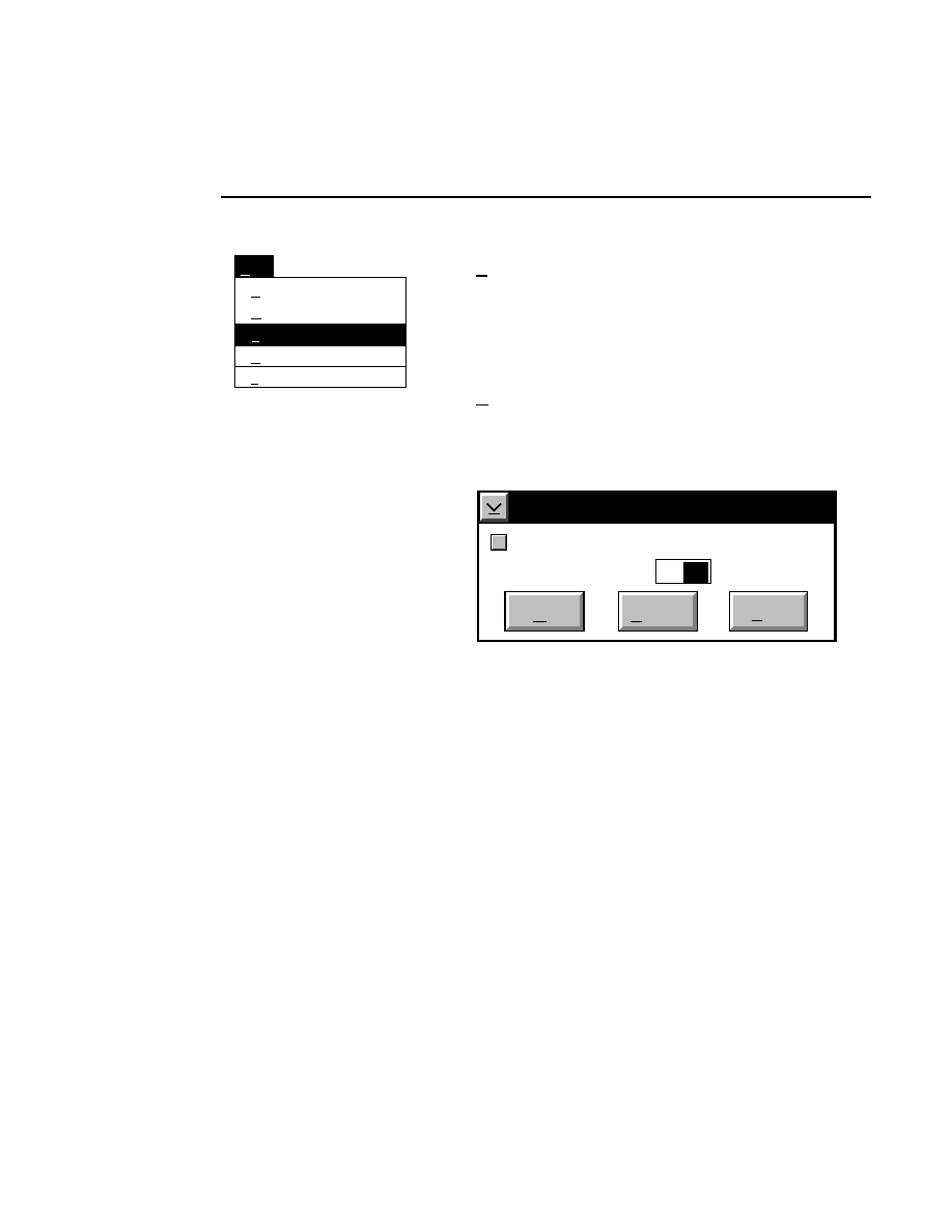
Section 6
6-4
Image Notepad - File Menu
Autosave...
Open...
File
New...
Ctrl+P
Save
Ctrl+S
Save
Ctrl + S
Saves the current Image Notepad file. The notepad will be
saved with the same filename as the associated Image file, and
will be given the extension
.INT
.
Autosave...
The Image Notepad can be automatically saved at a user-
selectable time interval, by entering the value in the Autosave
dialog box.
Autosave
At interval of: Minutes:
Cancel
OK
Help
✔
10
Autosave
Enter ‘0’ in the text entry field, or deselect the check box to
disable the Autosave feature.
Click
OK
to save changes, or
Cancel
to return to the Image
Notepad without saving changes.
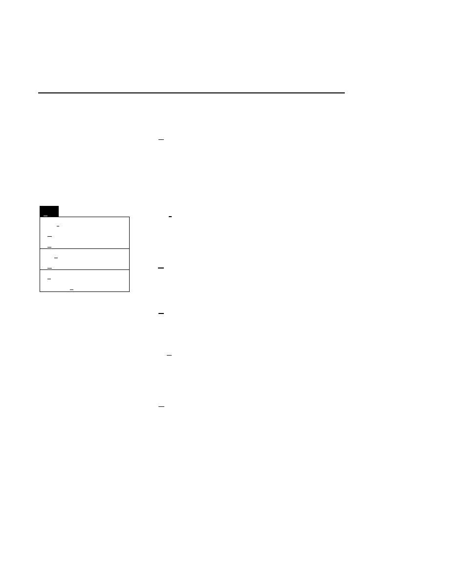
Image Notepad
Image Notepad - Edit Menu
6-5
Ctrl + P
Prints the current text in the Image Notepad to the system
printer.
The Edit Menu
Find...
Delete
Edit
Copy
Ctrl+F
Ctrl+Ins
Cut
Shift+Del
Paste
Shift+Ins
Clear
Select all
Cut
Shift + Del
Deletes selected text, and places it in the clipboard, for later
retrieval (until another selection is cut or copied).
Copy
Ctrl + Ins
Copies selected text to the clipboard, without removing it from
the Image Notepad.
Paste
Shift + Ins
Inserts text from the clipboard at the cursor position.
Clear
Replaces selected text with spaces. The selected text is not
copied.
Delete
Removes selected text without copying it to the clipboard.
NOTE: The Delete key performs this same function.
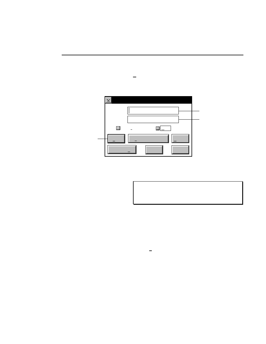
Section 6
6-6
Image Notepad - Edit Menu
Find...
Ctrl + F
The Find command opens a dialog box where you can search
the Image Notepad for user-specified text.
Find
Find:
Change
Help
Case sensitive
Wrap
Change to:
Change All
Cancel
Find
Change, then Find
Enter text to search for here
Enter replacement text
(optional) here
Press here to
begin search
✔
Enter the text to search for in the 'Find' text entry field. Enter
any replacement text in the 'Change to' text entry field.
NOTE: To search for both upper- and lowercase
occurrences of the text, disable the 'Case sensitive' check
box.
If the 'Wrap' check box is enabled, the text search will begin at
the cursor location, continue to the end of the file, and then
begin again at the start of the file. If disabled, the file will
only be searched from the cursor location to the end of the file.
Select all
Selects all text in the Image Notepad.
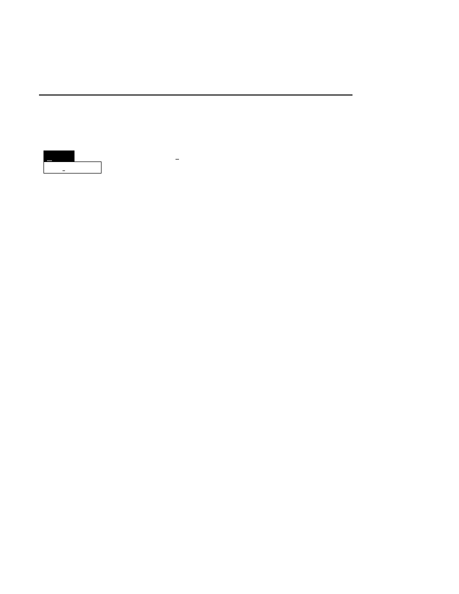
Image Notepad
Image Notepad - Options Menu
6-7
Options Menu
Options
✓
Wordwrap
Wordwrap
If selected, causes the text in the Image Notepad to wrap
according to the current size of the Image Notepad window, by
forcing line breaks at the right edge of the window. If
unchecked, text will extend beyond the edge of the window,
and may not be visible without using the scroll bars.
Selecting Wordwrap affects only the way text is displayed, and
does not actually insert carriage returns or line feeds into the
text file.

Section 6
6-8
Image Notepad
Opening the Image Notepad in Image Analysis
The Image Notepad is available only for review in Image
Analysis. Text cannot be edited or entered in Image Analysis.
Text can, however, be selected and copied to the clipboard,
where it can be pasted into the Sample Notepad for editing.
The Image Notepad is loaded along with its associated image
file when Open Image or Open Sample is selected from the
File menu in Image Analysis. For example, opening the image
file during Image Analysis entitled
T E S T . I M G
will
automatically load the associated Image Notepad file entitled
TEST.INT
.
The primary purpose of the Image Notepad in Image Analysis
is to review pertinent information concerning the gel
electrophoresis that is relevant to the sequencing operation
(e.g. the order in which the samples were loaded). It is also
useful for copying the lane loading format into the
Define/Verify Samples dialog box when performing auto-
sequencing of all samples.
There are two menus in the Image Notepad, as it appears in
Image Analysis; Edit and Options. Refer to the descriptions
of these text editing and printing functions earlier in this
section.
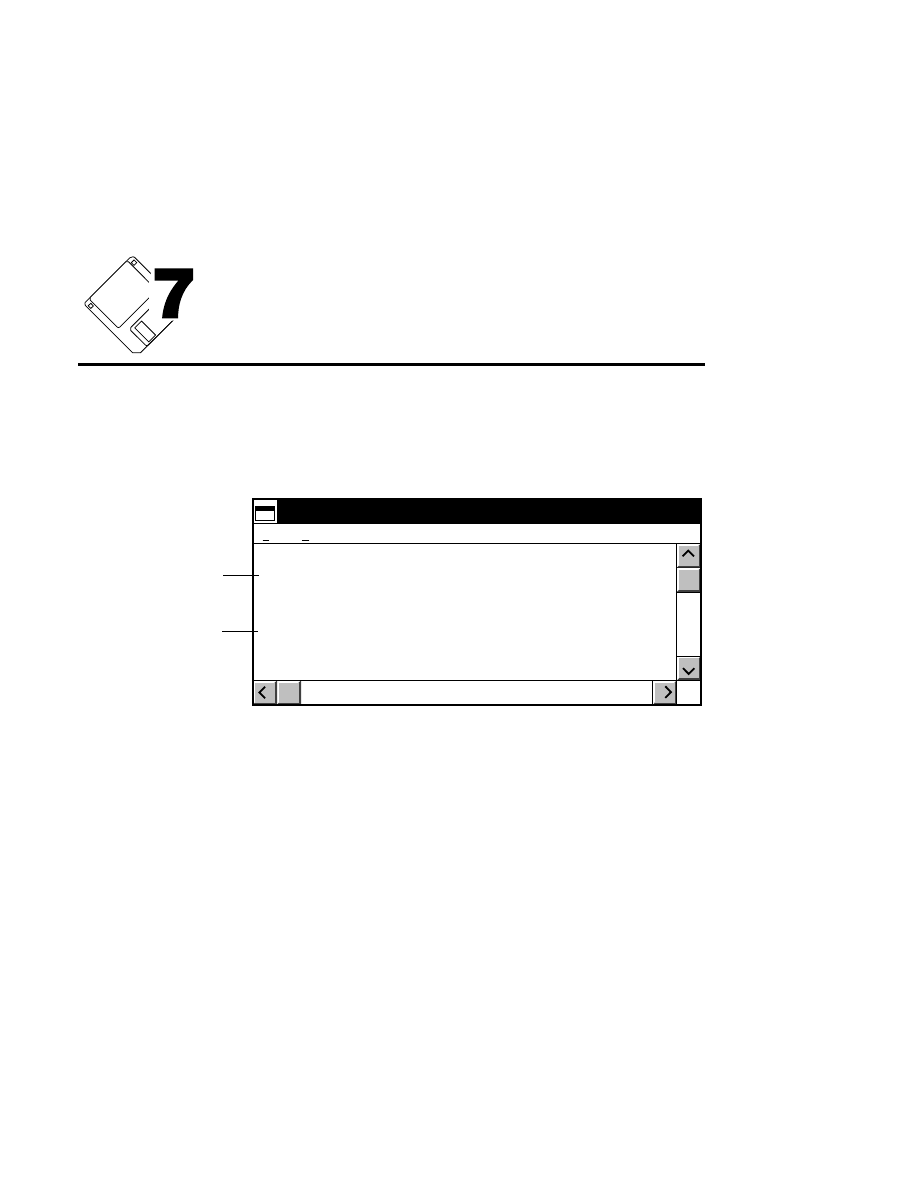
Log Notepad
7-1
Log Notepad
The Log Notepad is a text editor that is used to monitor and
record the operational parameters of the sequencer during Data
Collection.
Date Time Voltage (V) Current (ma)
I 920427 140330 918 34.2
C 920427 141135 926 34.0
I 920427 142330 948 33.1
C 920427 143908 0 0.0
Logged at interval
Logged at
parameter change
Log Notepad
Edit
File
Log Notepad files are automatically saved with the same file
name as the Image file, but with a
.LOG
extension.
The parameters that are recorded in the Log Notepad, and the
interval (in minutes) at which they are logged are chosen in the
Parameters Log List box. Open the Parameters Log List from
the Parameters menu in the Scanner Control window.
Recording the electrophoresis operating parameters is useful
for post-run analysis of the gel electrophoresis procedure, to
reproduce the set parameters from successful sequencing runs,
or to locate where problems may have occurred.
Section 7
7-2
Log Notepad - File Menu
An ‘I’ preceding a Log Notepad entry indicates the entry was
logged at the interval chosen in the Parameters Log List box.
A ‘C’ indicates the entry was logged due to a parameter
change initiated by the user.
Text can be entered or copied into the Log Notepad, or copied
from the Log Notepad into other applications.
There are two menus in the Log Notepad; the File and Edit
menus.
File Menu
Autosave...
Save
File
New
Ctrl + S
Ctrl + P
New
Erases all text in the Log Notepad. You will be prompted with
a message box asking if you want to erase the notepad. Press
OK
to clear the notepad, or
Cancel
to close the message box
without erasing the Log File.
Save
Ctrl + S
Saves the Log Notepad file. The notepad is saved with the
same filename as the Image file, and is given the extension
.LOG.
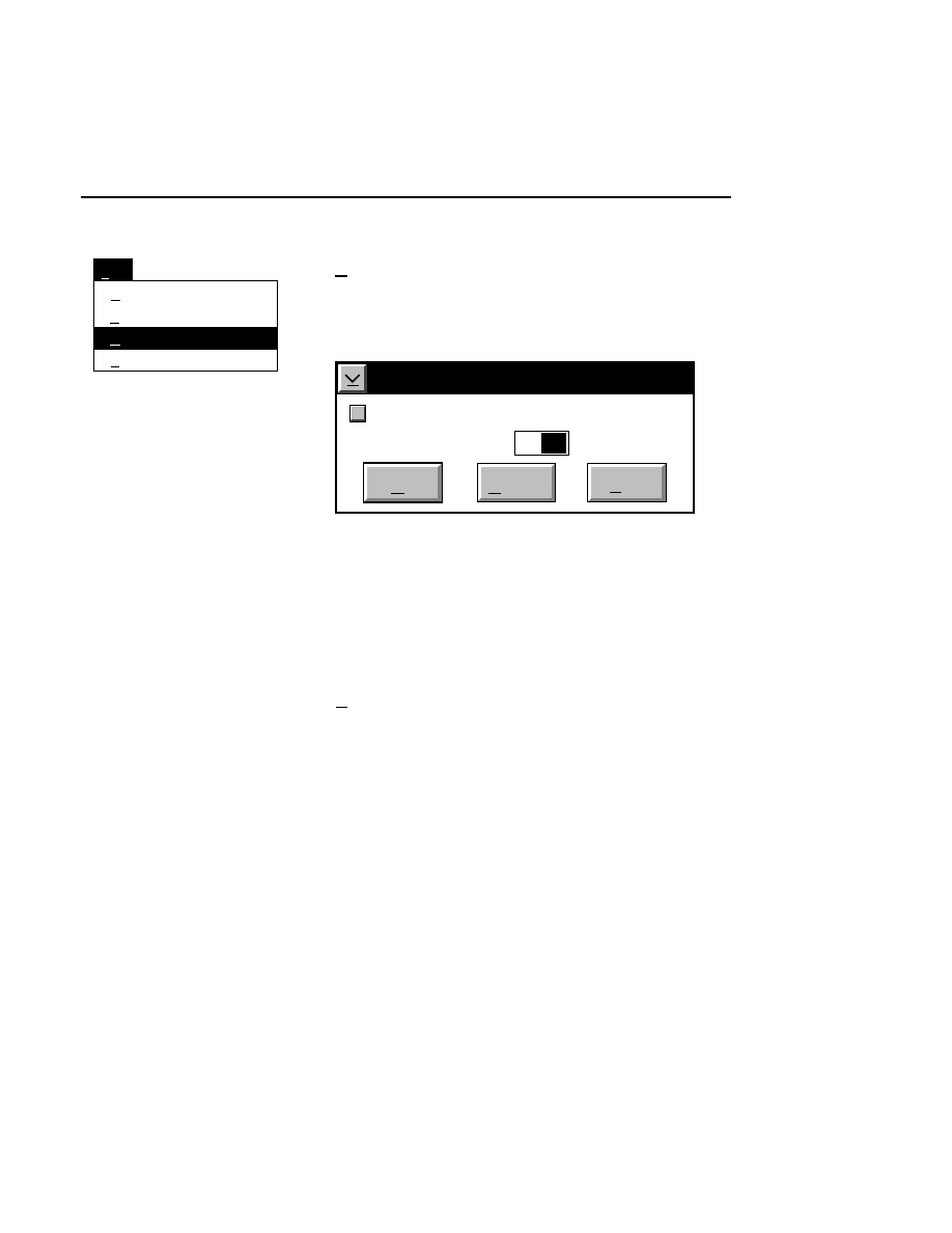
Log Notepad
Log Notepad - File Menu
7-3
Save
File
New
Ctrl + S
Ctrl + P
Autosave...
Autosave...
The Log Notepad can be automatically saved at a user-
selectable time interval, by entering the time (in minutes) in
the Autosave dialog box.
Autosave
At interval of: Minutes:
Cancel
OK
Help
✔
10
Autosave
Enter ‘0’ in the text entry field, or deselect the check box to
disable the Autosave feature. The default for Autosave is ON.
Click
OK
to save changes, or
Cancel
to return to the Log
Notepad without saving changes.
Ctrl + P
Prints the Log Notepad text to the system printer.
Section 7
7-4
Log Notepad - Edit Menu
Edit Menu
Paste
Copy
Edit
Cut
Ctrl+Ins
Shift+Del
Clear
Delete
Shift+Ins
Cut
Shift + Del
Deletes selected text, and places it in the clipboard, for later
retrieval (until another selection is cut or copied).
Copy
Ctrl + Ins
Copies selected text to the clipboard, without removing it from
the Log Notepad.
Paste
Shift + Ins
Inserts the contents of the clipboard into the Log Notepad at
the cursor position.
Clear
Replaces selected text with spaces. The selected text is not
copied to the clipboard.
Delete
Removes selected text without copying it to the clipboard.
NOTE: The Delete key performs this same function.

Image Analysis
1-1
Image Analysis
Table of Contents

1-2
Image Analysis


1-4
Image Analysis
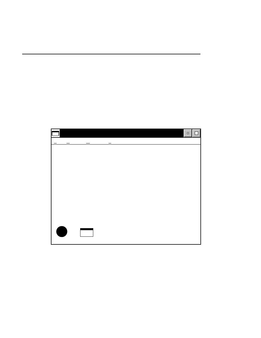
Image Analysis
Image Analysis
1-5
Starting Image Analysis
Image Analysis is opened by double-clicking the Image
Analysis icon in the Base ImagIR folder. The Image Analysis
window has four menus on the menu bar; File, Report,
Window, and Help. All other windows, including the Image
window, Sequence window, Sample and Image Notepads,
Configuration window, and Message window will open within
the borders of this window.
Base ImagIR Image Analysis <>
File Report Window Help
i
Messages
Configuration
Cfg
The Message window and the Configuration window initially
appear as icons when Image Analysis is opened.
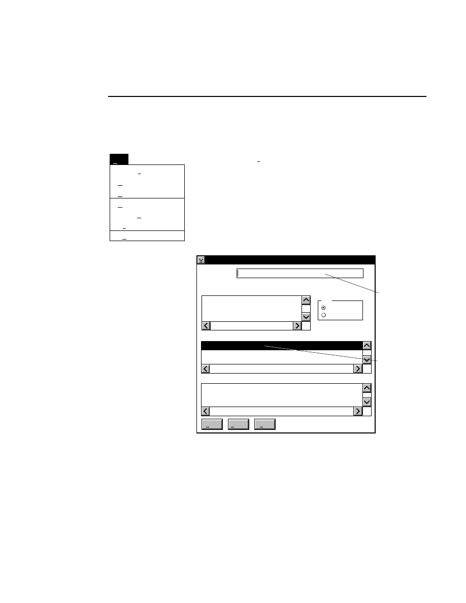
Section 1
1-6
Image Analysis Window - File Menu
File Menu
Save as...
Save
Open Sample...
New Sample
Autosave...
File
Exit F3
Open Image...
Open Image...
Loads an existing image file, created in Data Collection, so
that new sample files can be created. The Sequence window
and icons to open the Image and Sample Notepads also appear
in the Image Analysis window.
The
Open Image
dialog box is opened:
Open Image
Cancel
Help
Enter
Path: C:\DNA4000
Directories:
..
[A:]
[B:]
[C:]
Date:
Sort
Name
Date
Image:
Remarks:
The Image Remarks shown here were created during Data
Collection.
Enter the Image file
name here, or ...
double-click on the
filename here to
quickly open the
Image file
MMDDYY HHMMSS TESTIMG
Image file:
There are two ways to open an existing image file:

Image Analysis
Image Analysis Window - File Menu
1-7
1.
Type the path and name of the image file in the 'Image
File' field, and click
Enter
.
2.
Select the desired image file in the list box, and click
Enter
, or double-click on the desired image file. Use the
Directories list box to select the appropriate path.
To change the path, double-click on the desired directory in
the Directories list box. Double-click on “••” in the
Directories list box to move one level higher in the Path
hierarchy. For example, if the path listed is C:\DNA4000,
double-clicking on “••” will change the path to the root
directory (C:\).
The image files in the list box can be sorted according to the
date of the last modified file (most recent first), or alpha-
betically by name (in ascending order). Choose the sorting
method by selecting the appropriate radio button listed under
Sort
.
The Image Remarks text box displays any text entered into the
image remarks of the 'New' dialog box, when the selected
image file was first created. These remarks can not be edited,
but can be helpful in selecting the desired image file.
When an image file is opened, the filename will be displayed
in the Image Analysis window title bar.
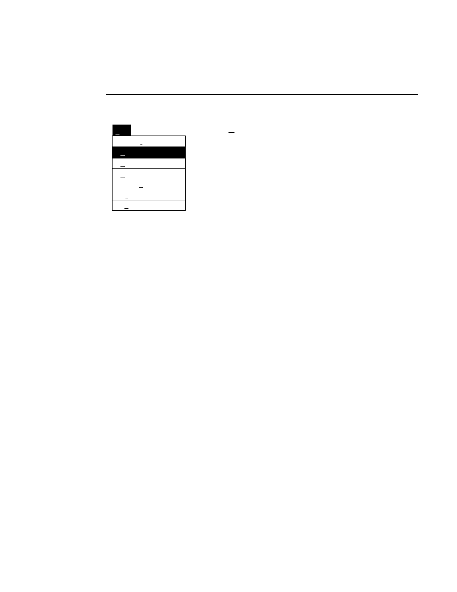
Section 1
1-8
Image Analysis Window - File Menu
Save as...
Save
Open Sample...
Autosave...
File
Exit F3
Open Image...
New Sample
New Sample
This menu item is available only while an image file is open.
A sample file is the file created during base calling, and
contains the sequence text, lane markers, band markers, and
smile corrections. Because multiple samples are normally
loaded onto a single gel during electrophoresis, a user may
typically want to sequence all samples on the image file
consecutively. To sequence all samples automatically, you
may want to use the Auto Sequence All Defined Samples
function (see description later in this section).
If a sample was sequenced prior to selecting New Sample, a
warning appears, requiring that you save the sample file, save
the file with a new name, or discard any changes made.
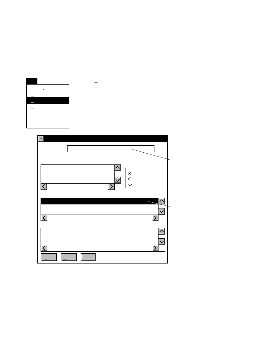
Image Analysis
Image Analysis Window - File Menu
1-9
Save as...
Save
New Sample
Autosave...
File
Exit F3
Open Image...
Open Sample...
Open Sample...
Loads an existing sample file and its corresponding image file
for editing or further sequencing. The Open Sample dialog
box is opened:
Open Sample
Cancel
Help
Open
Path: C:\DNA4200
Directories:
..
[A:]
[B:]
[C:]
Date
Sort by
Date
Sample file
Image file
Sample file
Image Remarks
Image file
Enter the sample
file name here, or ...
double-click
here to quickly
open the sample
file.
The Image Remarks shown here were created during the Data
Collection portion of the Base ImagIR programs.
MMDDYY HHMMSS SAMPLE#1 C:\DNA4200\M13TEST
Sample file:
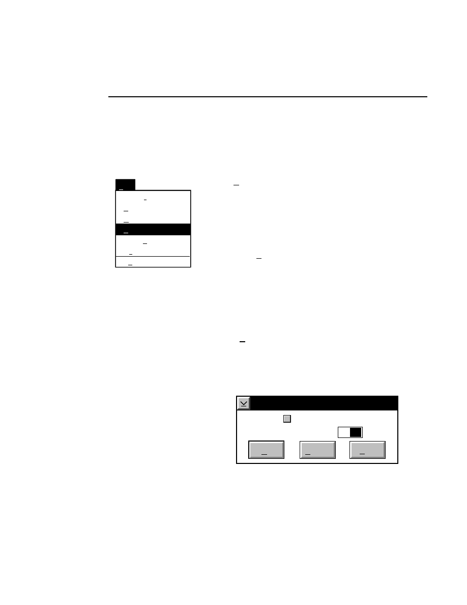
Section 1
1-10
Image Analysis Window - File Menu
The Open Sample dialog box is similar to the Open Image
dialog box, except that a previously created sample file is
loaded along with its associated image file.
Save as...
Open Sample...
New Sample
Autosave...
File
Exit F3
Open Image...
Save
Save
Saves the current sample and sample notepad files. If the
sample has not been named, the Save As dialog box is
displayed, which allows you to name the sample file, and
select or create the directory to which it will be saved.
Save as...
Saves the current sample file with a new filename specified in
the Save As dialog box (see description at Open Image).
When a sample is saved, the lane definitions, sequence text,
smile corrections and band markers are also stored with the
sample file.
Autosave...
The Sample and Sample Notepad files can be automatically
saved at a user-selectable time interval, by entering the value
in the Autosave dialog box. This menu choice is not available
until the sample file has been named.
Autosave
Interval in Minutes:
Cancel
OK
Help
✔
10
Autosave
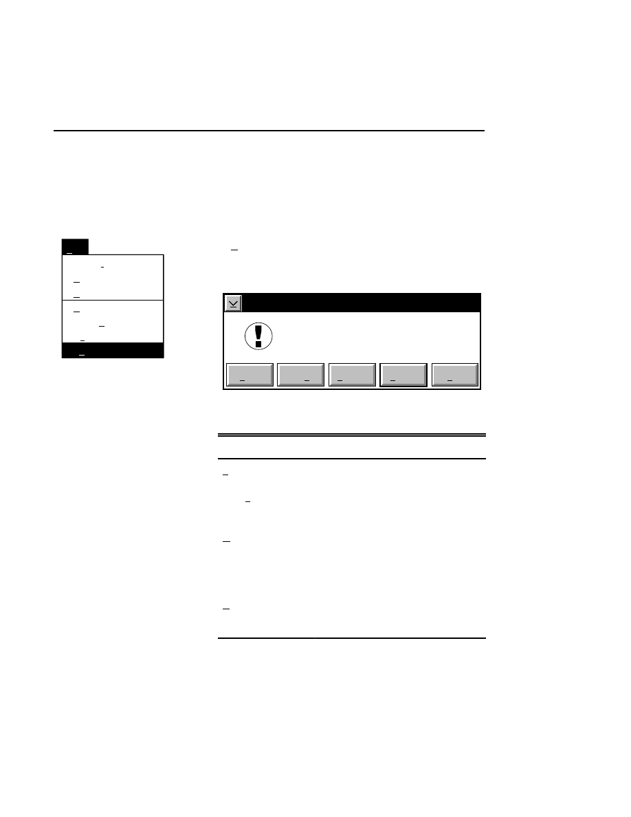
Image Analysis
Image Analysis Window - File Menu
1-11
Deselect the check box to disable the Autosave feature. The
default for Autosave is ON. Click
O K
to save changes, or
Cancel
to return to Image Analysis without keeping changes.
Save as...
Save
Open Sample...
New Sample
Autosave...
File
Open Image...
Exit F3
Exit
F3
Closes the Image Analysis program. If the sample is not
saved, you are prompted with a warning message:
EXIT-WARNING!
C:\DNA4200\TEST.SMP
has changed.
Do you want to save it?
Save as...
Save
Discard
Cancel
Help
In the
Exit Warning
box:
Press
to...
Save
Save the current sample file.
Save as
Save the current sample file with a new
filename.
Discard
Close Image Analysis without keeping
additional changes. All sequence
information collected since the last
Save (or Autosave) will be lost.
Cancel
Close the Exit Warning dialog box
without keeping changes.
Section 1
1-12
Image Analysis Window - Report Menu
Report Menu
Print...
Report
Ctrl+P
File...
Ctrl+D
Using the Report menu, sequence data from sample files can
be printed or exported for further analysis.
Reports can include Sequence data, Sample Remarks, Image
Remarks, and the Image, Sample, and Log Notepads. The File
and Print Report functions specify the data format and whether
the data are sent to a file or to the system printer.
File...
Ctrl + D
Exports the information to a plain text file. Selecting File
opens the File Report dialog box:
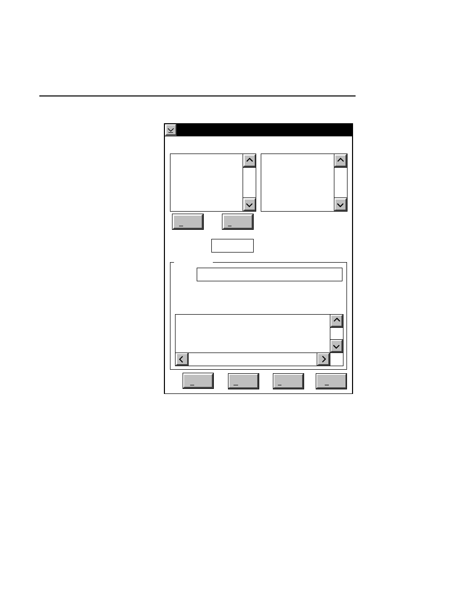
Image Analysis
Image Analysis Window - Report Menu
1-13
File Report
Reset
Help
Save
Delimiter: ..
SR
".."
S
Destination
Order
Directories
..
[A:]
[B:]
[C:]
New
Delete
SN Sample Notepad
SR Sample Remarks
S Sequence
DL Delimiter
FF Form Feed
IR Image Remarks
Options
File: UNTITLED.RPT
Directory is: C:\DNA4200\Data
Cancel
The parameters available for export (shown in the Options list
box) are:
●
Sample Remarks (SR) - Notes made in the Remarks field
of the Auto Sequence Setup dialog box Samples page.
●
Sample Notepad (SN) - Image Analysis notes.

Section 1
1-14
Image Analysis Window - Report Menu
●
Sequence (S) - sequence data.
●
Delimiter (DL) - character(s) which separate groups of
information such as marking the beginning or end of the
sequence data. Data analysis programs generally recognize
a unique delimiter, such as (..) or ($).
●
Form Feed (FF) - sends a form feed so that information
that follows appears on a new page. Some printers require
the presence of a form feed to send a document.
●
Image Notepad (IN) - notes made in the Image Notepad
during Data Collection.
●
Image Remarks (IR) - notes made in the Remarks field of
the 'New' dialog box in Data Collection.
●
Image Log (IL) - electrophoresis parameters recorded in
the Log Notepad during Data Collection.
The Order list box shows the parameters that will be exported.
One initial default File Report (as defined by the config-
uration) is to export the Sample Notepad (SN), the Delimiter
(••), and the Sequence data (S). Click on the
New
button to
clear all of the entries from the Order list box. Click on the
Delete
button to remove only the selected parameter from the
Order list box.
The default File and Print Report formats can be set in the
configuration file so that the preferred format is always
displayed in the Order list box.
Double-click on the parameters in the Options list box to add
them to the Order list box. Parameters can be inserted at any
position in the Order list box. If a parameter is highlighted in

Image Analysis
Image Analysis Window - Report Menu
1-15
the Order list box, new parameters will be added ahead of the
selected one. If no parameters are highlighted, new ones will
be added to the end of the list.
To change the Delimiter in the text entry field, select it and
type in the new text, and then add it to the Order list box.
The Destination determines where the File Report will be sent.
Type the complete path and the filename of the report in the
'File' field. If no path is specified, the report will be exported
to the Directory listed. Use the Directories list box to change
the active directory.
Example: Type
D:\MYFILE
in the 'File' field to send a File
Report entitled
MYFILE
to the optical disk drive (assuming
that the optical drive is designated as the D: drive).
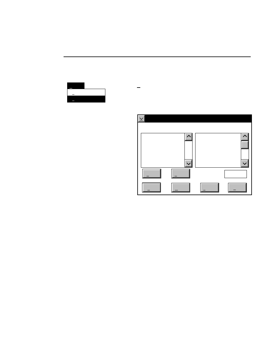
Section 1
1-16
Image Analysis Window - Report Menu
Report
File...
Ctrl+D
Print...
Ctrl+P
Print...
Ctrl + P
The Print Report command is similar to the File Report
command described above, except that data are printed to the
system printer.
Print Report
Reset
Help
Delimiter: ..
SN
".."
S
Order
New
Delete
SN Sample Notepad
SR Sample Remarks
S Sequence
DL Delimiter
FF Form Feed
IR Image Remarks
Options
Cancel
Image Analysis
Image Analysis Window - Window Menu
1-17
Window Menu
Window
Cascade
1. Messages
2. Configuration
3. Image
4. Sequence
5. Sample Notepad
6. Image Notepad
Shift+F5
✓
Cascade
Shift + F5
Arranges the windows with a stairstep overlap, with the title
bar of each window visible and the active window on top.
The active window is denoted by a ✓ before the menu item.
Selecting any of 1: - 6: will cause the associated window to
become active (the title bar will be highlighted, and it will be
placed on top if the windows overlap). If the selected window
is minimized, it will be restored when selected.
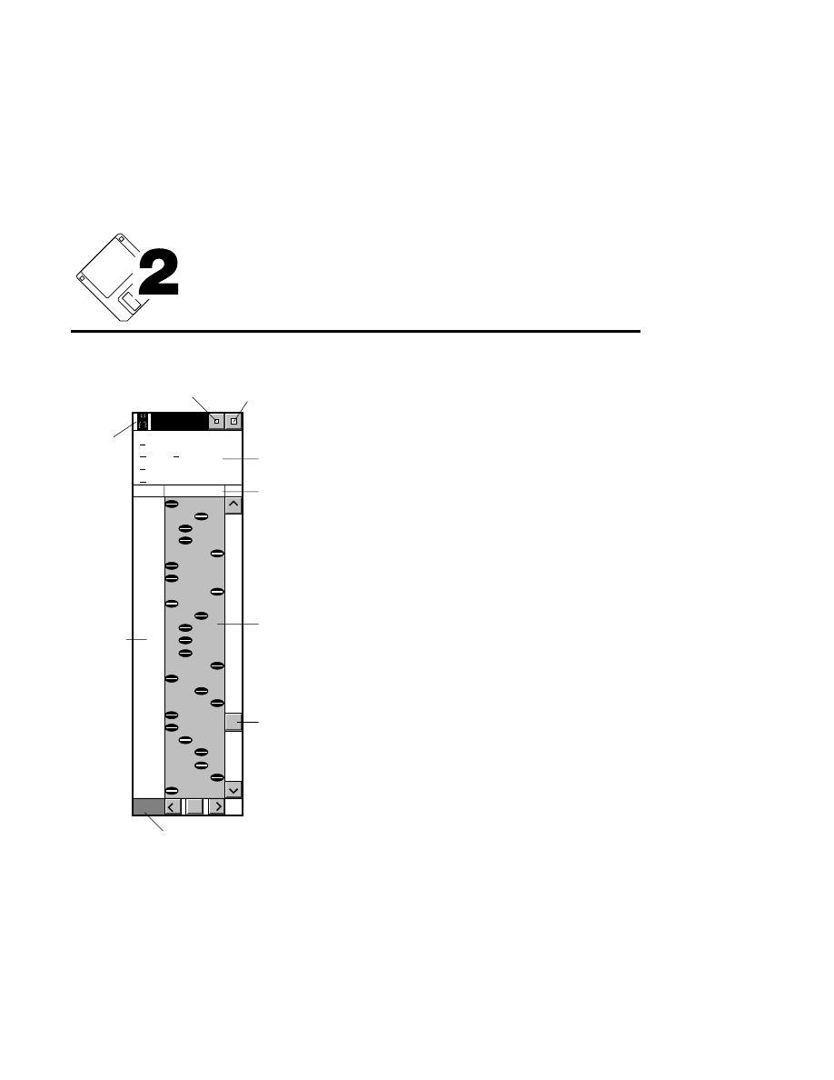
Image Window
2-1
Image Window
Image
Sequence
Goto
Enhancement
Options
View
F1
A T G C
24
System
menu
Minimize icon
Maximize icon
Image
Sequence
Slider bar
Frame number
Lane definition
Menu bar
G
T
A
C
G
T
C
G
A
T
G
A
A
T
C
A
A
T
T
A
C
A
G
C
The Image window displays the image file
created during Data Collection. The five menus
on the Image window menu bar contain the
commands used for base calling. Note that the
Quick SequencIR program (see A u x i l i a r y
Programs) can be used to automatically call
bases from all samples during Data Collection.
The various parts of the Image window are
shown at left (graphic representation shown in
Single Sample View, with black bands on a white
background).
The Image window can be moved, resized,
minimized to an icon, or sized to view a single
sample (after the lanes have been defined) or the
entire image.
Section 2
2-2
Image Window - Sequence Menu
Sequence Menu
Ctrl + L
Sequence Settings...
Sequence
Lane definition...
Ctrl + X
Ctrl + Q
Auto Sequence All...
Semi-automatic
Ctrl + E
Auto Single Sample...
Manual/Edit
Ctrl + M
Band spacing...
Ctrl + B
Auto band spacing...
Ctrl + C
Auto Sequence All...
Ctrl + Q
Opens the Auto Sequence Setup dialog box (below), where
you define the loading order of the samples (Load tab), and
name the samples (Samples tab).
The loading order must be defined accurately in order for the
auto lane finding and autosequencing software to function
properly.
The bottom portion of the page shows a 'Comb Loading' text
field into which the lane definition for all samples is entered.
The 'Comb Loading' field is a very important part of the
notebook page. This is where the lane loading order is
defined. The software uses this information to find the lanes
and call bases.
Along with the base designators (A,T,G,C), two other
symbols, 'X' and '_' (underscore) are used in the ''Comb
Loading' field. An X is used to indicate a lane that was
loaded, but is not part of any sample, and a '_' is used to
designate a lane that was not loaded.
The Mutation Analysis Loading Format is used for genetic
analysis, where samples are loaded in a format such as
AAAATTTTGGGGCCCC.
Image Window
Image Window - Sequence Menu
2-3
Reset
Cancel
Find Lanes
Sequence
Help
Auto Sequence Setup
Loading Information
Comb: 32-Well Rectangular
Lane Order (A,T,G,C,'-'(empty)): ATGC
Number of Samples: 4
Formats
No Selected Lanes
Comb Loading: A,T,G,C,X (nonsequence load),'-'(empty lane)
ATGC_ATGC_ATGC_ATGC
Standard Loading Format
Mutation Analysis Loading Format
Samples
Load
Auto Sequence Setup dialog box (Load page).
Example
You typically use a 48-well sharkstooth comb to load 12
samples in standard loading format. Follow these steps to
define the loading information:
1.
Select '48-well sharkstooth comb' in the Comb field.

Section 2
2-4
Image Window - Sequence Menu
2.
Make sure that the 'Standard Loading Format' radio button
is enabled.
3.
Enter the lane loading order in the 'Lane Order' field (i.e.,
ATGC).
4.
Use the up arrow to scroll the 'Number of Samples' field
to 12. Alternatively, you could select the text and type in
12.
5.
Verify the Comb Loading field. If you have any wells
that were loaded but not used, or any empty lanes, insert
the cursor at the well position and type in an 'X' for
nonsequence loads, or a _ (underscore) for empty lanes.
6.
Click on the Samples tab and enter a default file name that
will be used for the sample files. Limit the file name to 6
characters or less, as the name will be appended with a 2-
digit number.
7.
To begin sequencing, click on
Find Lanes
. The
Find/Verify Lanes dialog is opened. Click
Find
. The
sample lanes will be located.
8.
Click
Sequence
. The Auto Sequence All Defined
Samples dialog will open. Enter the sequencing
parameters and click
Start
.
Image Window
Image Window - Sequence Menu
2-5
Samples Page
Reset
Cancel
Find Lanes
Sequence
Help
Auto Sequence Setup
No. Sample Name Remarks
1 SAMPLE1
2 SAMPLE2
3 SAMPLE3
4 SAMPLE4
Sample Name(s): SAMPLE
Samples
Samples
Load
Create Report Files Create SCF Files
✔
Auto Sequence Setup dialog box (Samples page).
The number of sample names displayed is determined by the
number of samples entered in the Load Notebook page.
In the 'Sample Name(s)' field, enter the name for the sample
file(s). This name will automatically be appended with a one-
or two-digit number (1, 2, 3, ... 10, 11 etc.) and a .SMP file
extension. For example, if you enter 'Test' for the Sample
Name, and have defined 8 samples in the Load Notebook
Section 2
2-6
Image Window - Sequence Menu
page, you will see 8 sample files listed, entitled Test1, Test2,...
Test8. You can manually edit any sample name or remarks by
selecting the text in the field and typing the new text.
File reports and/or SCF files can be generated automatically
for each sample sequenced using the Auto Sequence All
function. The parameters that will comprise the File Report
(including the default file report extension) are derived from
the Reports Notebook pages. To automatically generate report
files for each sample, enable the ‘Create Report Files’ check
box. To generate SCF files, enable the 'Create SCF Files'
check box.
Sequence Settings...
Sequence
Lane definition...
Ctrl + X
Ctrl + Q
Auto Sequence All...
Semi-automatic
Ctrl + E
Auto Single Sample...
Manual/Edit
Ctrl + M
Band spacing...
Ctrl + B
Auto band spacing...
Ctrl + C
Ctrl + L
Lane Definition...
Ctrl + L
Before manual or automatic sequencing of a single sample, the
four vertical lanes that delineate each base group in the sample
must be defined.
Lanes are defined according to the order the reaction mixes
were loaded onto the gel. To define the lanes:
1.
Select
Lane definition
from the
Sequence
menu
in the
Image window. The Lane definition dialog box opens.
2
.
Double-click on the letter corresponding to the base in the
lane on the left side of the sample. N O T E : It is
advantageous to define lanes from left to right, as there are
shortcuts that speed lane definition.
Image Window
Image Window - Sequence Menu
2-7
Lane Definition
Base
C
G
T
Cancel
Reset
OK
Help
Move Lanes
Del. Lanes
Double-click here
A
A vertical lane marker appears in the Image window.
3
.
Move the mouse until the lane marker is positioned at the
left edge of the vertical column of bases. Click the mouse
button, hold, and move to the right edge of the lane, and
release the mouse button. The first mouse click anchors
the left edge of the lane marker, and releasing the button
anchors the right edge of the lane marker. The
corresponding letter appears above the lane just defined.
NOTE: If you make a mistake defining the lanes,
press the
Reset
button, and begin again, or double-
click on the last base designator and redo it.
4
.
Double-click on the letter corresponding to the second
lane to define in the
Base
list
box. Another lane marker
appears in the Image window.
5
.
Move the lane marker into the lane already defined, and
click and hold the mouse button again. Notice that the

Section 2
2-8
Image Window - Sequence Menu
marker turns red when it enters the first lane, to indicate
that a lane was already defined in that location. The
marker will jump to the right edge of the first lane, which
also automatically defines the left edge of the second lane.
6
.
Move the marker to the right edge of the second lane, and
release the mouse button. The second letter appears
above the newly defined lane. Note that this short-cut is
useful only if the two lanes are adjacent to each other; if
they are not, you must follow the procedure described at
step 3 above.
7
.
Repeat steps 4, 5 and 6 to define the third and fourth
lanes.
8
.
Click
OK
. The lane markers will disappear.
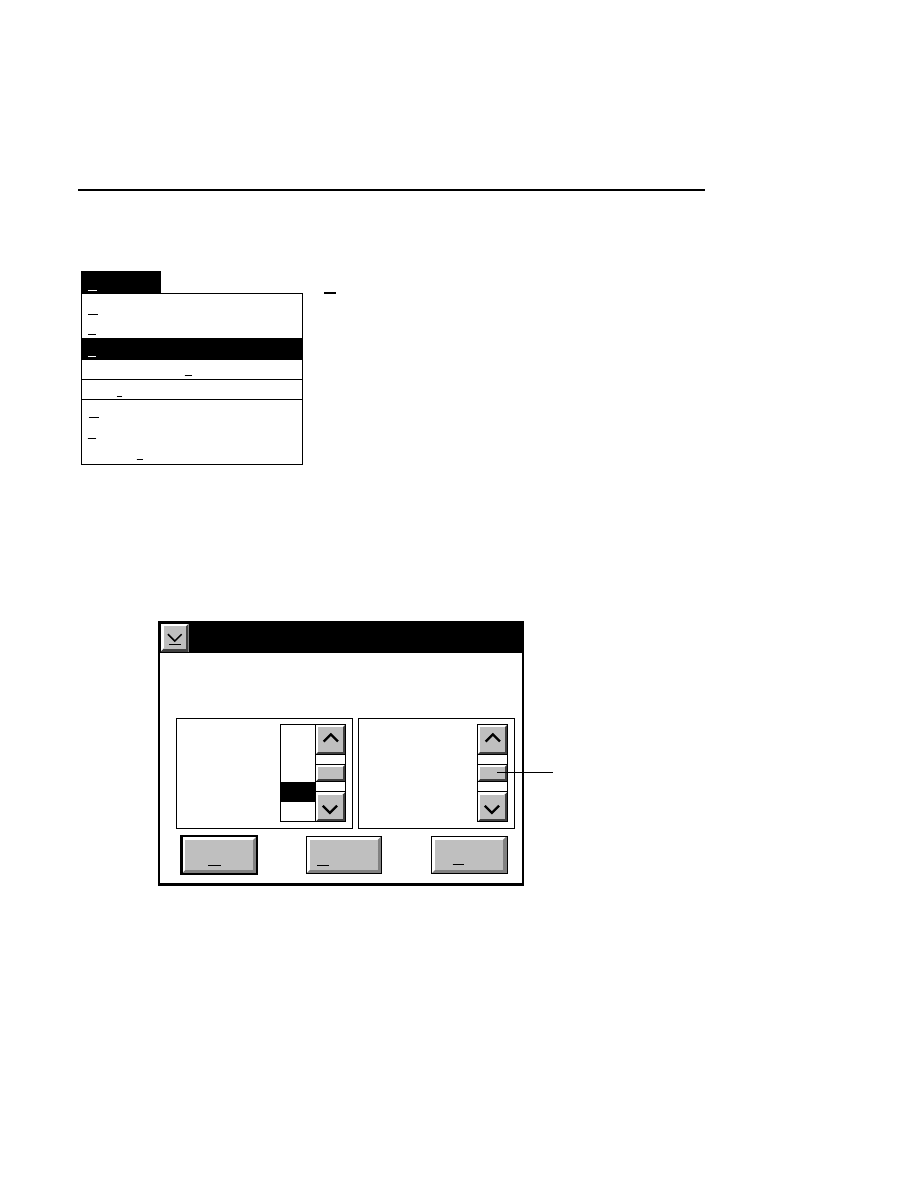
Image Window
Image Window - Sequence Menu
2-9
Ctrl + L
Sequence Settings...
Sequence
Lane definition...
Ctrl + X
Ctrl + Q
Auto Sequence All...
Semi-automatic
Ctrl + E
Auto Single Sample...
Manual/Edit
Ctrl + M
Band spacing...
Ctrl + B
Auto band spacing...
Ctrl + C
Band Spacing...
Ctrl + B
The Band Spacing command determines the vertical distance
(in display pixels) over which the cursor in the Image window
will “jump” during base calling, either by moving the mouse
(in Manual sequencing), clicking the mouse button (Semi-
automatic sequencing), or automatically during Automatic
sequencing.
In general, if electrophoresis is conducted at constant power,
the center-to-center distance between bands remains relatively
constant throughout the image file. Minor adjustments to the
band spacing may be needed during Manual or Semi-automatic
sequencing, however. The band spacing is automatically
adjusted during Automatic sequencing. You can also use the
Auto Band Spacing command (below) to calculate the band
spacing while in manual or semi-automatic sequencing modes.
Band Spacing
Current spacing: 15
-2
-1
Cancel
OK
Help
Change
spacing
by:
+2
0
+1
Move
baseline:
Use this scroll bar
to move grid
New spacing: 16

Section 2
2-10
Image Window - Sequence Menu
The video display is composed of 1024 horizontal pixels
×
768
vertical pixels. The image visible in one frame of data is 512
pixels tall. The numbers in the 'Current' and 'New spacing'
text fields represent the number of vertical pixels in the Image
window over which the cursor will “jump” during sequencing.
When the band spacing dialog box is opened, a horizontal grid
is placed over the image. This grid corresponds to the number
of pixels indicated in the New spacing' field of the Band
Spacing dialog box. If the spacing is correct, each horizontal
grid will align with a band (although not all lines will be
centered in the band). Increasing the numerical value of the
band spacing will move the grid lines further apart.
Decreasing the value will move the grid lines closer together.
The entire grid can be moved up or down to "fine tune" the
reference position, by using the scroll bars on the right side of
the dialog to move the baseline.
In the graphic illustration below, the band spacing grid on the
left image is properly aligned, with each horizontal grid nearly
centered in the bands. In the right image, the band spacing
value is too small, and should be increased to be properly
aligned.
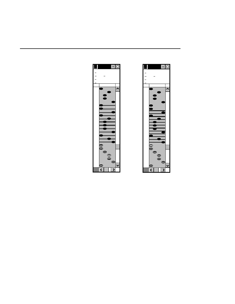
Image Window
Image Window - Sequence Menu
2-11
Image
Sequence
Goto
Enhancement
Options
View
F1
A T G C
8
C
A
A
T
G
G
C
A
Image
Sequence
Goto
Enhancement
Options
View
F1
A T G C
8
C
A
A
T
G
G
C
A
Another way to determine the proper band spacing is to place
the sequencing cursor over one of the bands near the
beginning of the run. Move the mouse forward so that the
cursor “jumps” to the next band. If the cursor does not reach,
or extends beyond the center of the second band, it will be
necessary to increase or decrease the band spacing,
respectively. Use the scroll bars to select the number of lines
in which to increment the step value. The 'New spacing' field
will reflect the selected change. Double click on the desired
step value change, or select it and click
OK
to implement the
Section 2
2-12
Image Window - Sequence Menu
change in Band spacing. Readjust as required, until the cursor
“jumps” from band to band properly.
Each time the Band Spacing dialog box is opened, the 'New
spacing' field will automatically increment or decrement the
band spacing by the same amount as the last time it was
opened. This allows you to just press
Enter
to select the same
increase or decrease again, which can be useful for manual or
semi-automatic sequencing. Press
OK
to implement the band
spacing that appears in the 'New spacing' text field.
Ctrl + L
Sequence Settings...
Sequence
Lane definition...
Ctrl + X
Ctrl + Q
Auto Sequence All...
Semi-automatic
Ctrl + E
Auto Single Sample...
Manual/Edit
Ctrl + M
Band spacing...
Ctrl + B
Auto band spacing...
Ctrl + C
Auto band spacing
Ctrl + C
The Auto band spacing function automatically calculates band
spacing using the same algorithm employed in automatic
sequencing. When a band is marked, and Auto Band Spacing
is selected, the proper band spacing will be calculated at the
location of the cursor, and adjustments will be made as needed.
When the cursor is moved again, the new spacing will be
implemented. The result is the same as using the band spacing
dialog box described above, with the exception that the
spacing is calculated automatically, without the need to open a
dialog box. The band spacing is not, however, continuously
calculated during the course of semi-automatic or manual base
calling; you must periodically invoke the function to
recalculate the proper band spacing.
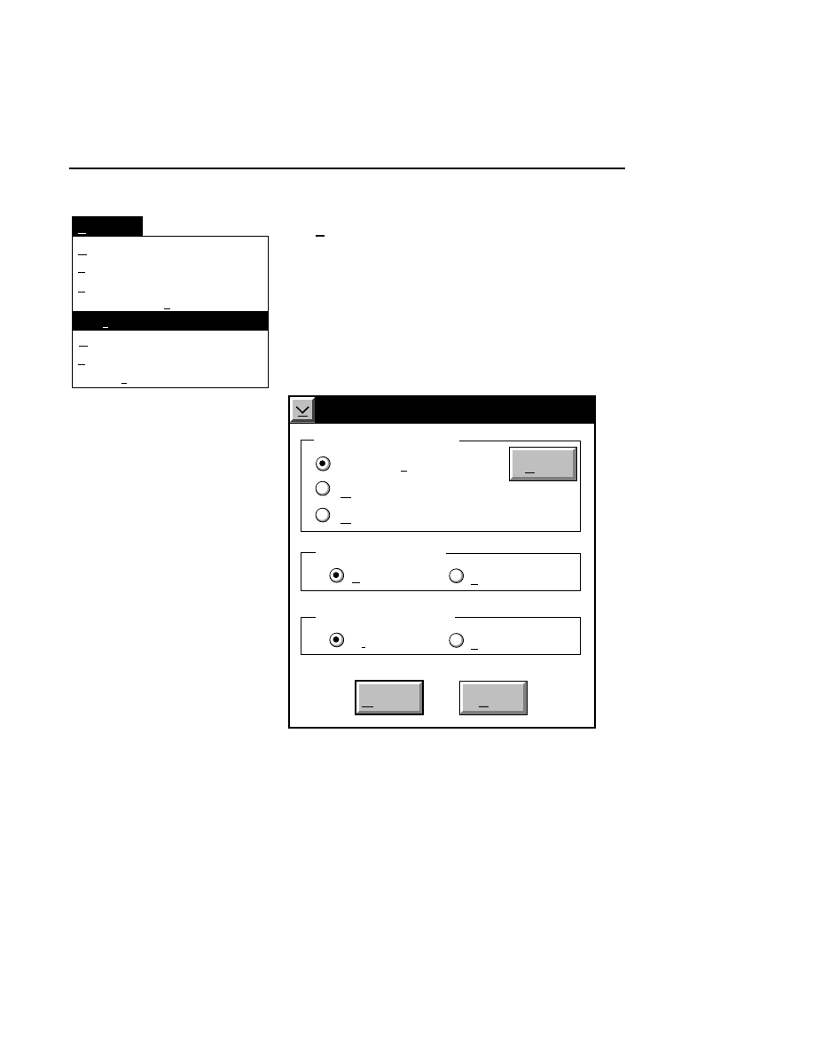
Image Window
Image Window - Sequence Menu
2-13
Ctrl + L
Sequence Settings...
Sequence
Lane definition...
Ctrl + X
Ctrl + Q
Auto Sequence All...
Semi-automatic
Ctrl + E
Auto Single Sample...
Manual/Edit
Ctrl + M
Band spacing...
Ctrl + B
Auto band spacing...
Ctrl + C
Sequence Settings...
Ctrl + X
During the sequencing operation, you may encounter
ambiguous bands in the image, which can be marked with a
variety of different symbols. The Ambiguities dialog box and
the Image window are interactive, meaning that ambiguities
can be marked in the Image window when the Ambiguities
dialog box is open. When an ambiguity is marked, a red
marker is placed over the band, and the ambiguity symbol
appears in the Sequence text.
Sequence Settings
Dismiss
Help
Ambiguities Symbol
Modified IUPAC
'N' for all
'X' for all
Base Calling Mode
Standard
Heterozygous
Show
Ambiguities Case
Upper
Lower
Ambiguities can be coded with any of three different symbol
sets:

Section 2
2-14
Image Window - Sequence Menu
1.
Modified International Union of Pure and Applied
Chemistry (IUPAC) codes.
2
.
‘N’ for all marked ambiguities.
3
.
‘X’ for all marked ambiguities.
During automatic sequencing, the ‘Use Ambiguity Symbols’
check box must be selected to use ambiguity symbols during
base calling.
Marking Ambiguous Bases
1
.
Select
Sequence Settings
from the Sequence
menu. The
Sequence Settings dialog box appears. Select the symbol
set that you want to use to mark the ambiguities. Click
Dismiss
.
2
.
Place the cursor in the Image window. As an example,
assume that there is a location in the image that has bands
in the C and T lanes at the same horizontal position.
Double-click the right mouse button on each of the two
bands. A 'Y' appears in the sequence (if the IUPAC radio
button is selected), and a red marker appears over each
band. According to the IUPAC Ambiguity Code, a 'Y' is
used to indicate an ambiguity that could be either C or T.
3
.
If you do not want to use the IUPAC code, you can mark
all ambiguous bases with an 'N' or an 'X' by selecting the
appropriate radio button. Upper and lowercase letters are
also available for all ambiguity codes by selecting the
appropriate radio button.
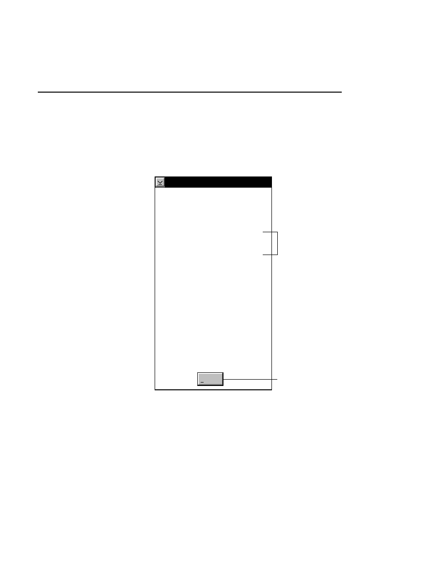
Image Window
Image Window - Sequence Menu
2-15
The IUPAC Ambiguity codes have been modified by LI-COR
to include lowercase a, t, g, and c symbols, to indicate bases
called which are a questionable A, T, G, or C, respectively.
The Modified IUPAC Ambiguity codes are shown below.
(*Modified) IUPAC Ambiguity Code
Dismiss
A
C
G
T
a
c
g
t
R
Y
M
K
W
S
B
D
H
V
N
Adenine
Cytosine
Guanine
Thymine (Uracil)
Questionable A
Questionable C
Questionable G
Questionable T (U)
A or G
C or T (U)
C or A
G or T (U)
A or T (U)
C or G
C or G or T (U)
G or A or T (U)
A or C or T (U)
A or C or G
Either A, C, G, or T (U)
*
*
*
*
Additional codes
added by LI-COR
Press here to close the
IUPAC Code dialog box.
Select the ‘N’ for all or ‘X’ for all radio buttons to mark all
ambiguities with an N, or X, respectively.
Select the Upper or Lower radio button to mark ambiguities
with upper- or lowercase symbols, respectively.

Section 2
2-16
Image Window - Sequence Menu
The Base Calling Mode radio buttons determine the algorithm
that is used during base calling. When
Heterozygous
base
calling is enabled, the software looks specifically for
heterozygotes (more ambiguities). In other words, the
software is more sensitive to ambiguities, for more accurate
mutation detection.
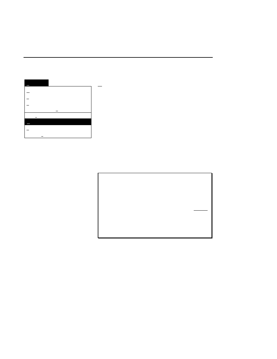
Image Window
Image Window - Sequence Menu
2-17
Ctrl + L
Sequence Settings...
Sequence
Lane definition...
Ctrl + X
Ctrl + Q
Auto Sequence All...
Semi-automatic
Ctrl + E
Auto Single Sample...
Manual/Edit
Ctrl + M
Band spacing...
Ctrl + B
Auto band spacing...
Ctrl + C
Manual/Edit
Ctrl + M
In Manual sequencing mode, the user controls all aspects of
base calling, including moving the cursor and selecting bases.
When Manual/Edit is selected, the mouse pointer changes to
an ‘X’-shaped sequencing cursor when it is moved into a
defined lane in the image. NOTE: Lanes must be defined
before Manual sequencing can be enabled.
Bases are selected by placing the cursor over the base and
clicking the left mouse button. The sequence text will appear
in the Sequence window, and at the left edge of the Image
window. Moving the mouse up causes the cursor to “jump”
the vertical distance determined by the Band Spacing setting.
Hint: If the cursor does not precisely align with the
center of the base(s) when sequencing in Manual or Semi-
automatic modes, adjust the Band Spacing, if desired
using the Band Spacing or Auto Band Spacing functions.
Alternatively, the band spacing function can be disabled
temporarily, and the cursor moved up or down (without
marking the base) to align with the center of the base, by
clicking and holding the right mouse button while
dragging the mouse. This will establish a new baseline
without opening the Band Spacing dialog box.
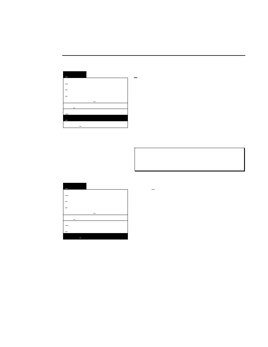
Section 2
2-18
Image Window - Sequence Menu
Ctrl + L
Sequence Settings...
Sequence
Lane definition...
Ctrl + X
Ctrl + Q
Auto Sequence All...
Semi-automatic
Ctrl + E
Auto Single Sample...
Manual/Edit
Ctrl + M
Band spacing...
Ctrl + B
Auto band spacing...
Ctrl + C
Semi-automatic
Ctrl + E
In Semi-automatic sequencing mode, when a base is selected,
the cursor automatically “jumps” to the lane in which the next
base is located. The vertical distance is determined by the
Band Spacing setting, and the computer determines which lane
the base is in. The user can then verify the choice by clicking
the mouse button, or override the choice by manually moving
the cursor to another lane.
When you reach the top of frame during sequencing, click the
sequencing cursor in the white area of the Image window
containing the lane designators to scroll the image.
NOTE: As with Manual sequencing mode, the lanes must
be defined before Semi-automatic sequencing can be
enabled.
Ctrl + L
Sequence Settings...
Sequence
Lane definition...
Ctrl + X
Ctrl + Q
Auto Sequence All...
Semi-automatic
Ctrl + E
Auto Single Sample...
Manual/Edit
Ctrl + M
Band spacing...
Ctrl + B
Auto band spacing...
Ctrl + C
Auto Single Sample...
In Automatic sequencing mode, the software calls all of the
bases in the sample for which the lanes have been defined. It
also automatically corrects the band spacing, compensates for
"smiles", and marks ambiguities.
Autosequencing requires that the lanes be defined and a
starting point (i.e., at least one base) be marked, using either
the Manual or Semi-automatic sequencing mode.
Selecting Auto Single Sample from the Sequence menu opens
the Automatic Sequence-Single Sample dialog box:
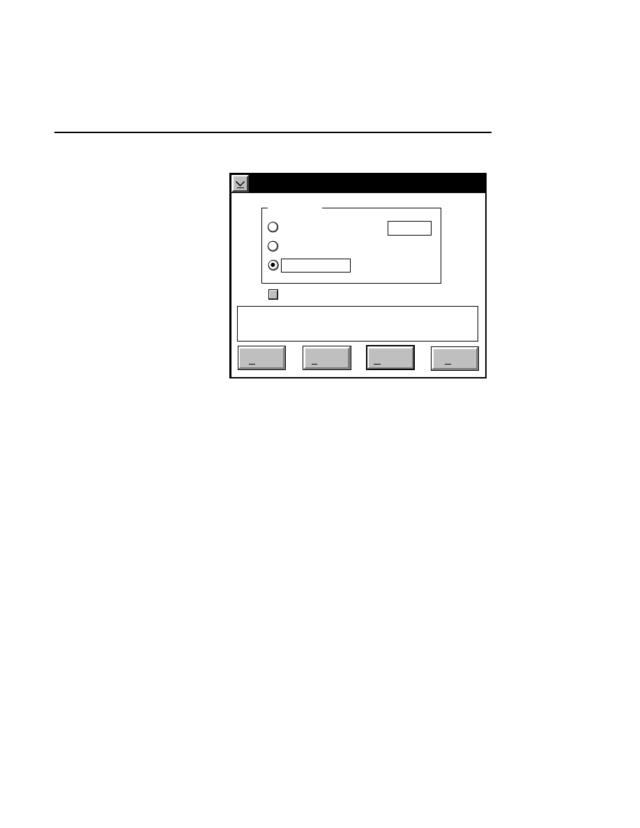
Image Window
Image Window - Sequence Menu
2-19
Automatic Sequence - Single Sample
Start
Help
Number of bases:
Sequence
Pause
Cancel
500
Auto stop
Use Ambiguity Symbols
To end of file
✔
The number of bases to be sequenced is determined by the
three sequence radio buttons:
Number of bases - enter the number of bases to be sequenced,
beyond the starting point. For example, if 100 bases have
already been sequenced, entering “500” causes the software to
sequence from bases 101 to 600.
Autostop - when selected, the software will sequence until a
level of confidence can not be maintained.
To end of file - when selected, the software will sequence to
the end of the image file, regardless of accuracy.
If the ‘Use Ambiguity Symbols’ check box is selected,
ambiguous bases will automatically be marked with the
symbol set selected in the Ambiguities dialog box, depending
upon what the software determines is its "best guess" for the

Section 2
2-20
Image Window - Sequence Menu
band in that location. If this check box is disabled, no
ambiguity symbols will be used to mark the bases.
In the
Automatic Sequence - Single Sample
dialog box:
Press
to...
Start
Begin sequencing according to the
limits specified by the Sequence radio
buttons. After a starting point has been
marked, and Autosequencing has been
initiated, this button will change to
Quit
.
Pause
(Continue)
Pause Automatic sequencing, until
Continue
or
Quit
is pressed. After
pausing the operation, this button
becomes
Continue
.
Quit
Stop Automatic sequencing without
marking any further bases.
Image Window
Image Window - Sequence Menu
2-21
Autosequencing Example
Below is an example to demonstrate the steps you would take
to define two samples that were loaded onto the gel (reading
from left to right when facing the instrument), as shown in the
diagram below. In this diagram, note that lane #5 was not
loaded, and lane #6 was loaded, but not used, because the well
was damaged during loading. It is important that you note the
position of gaps, or lanes that were loaded but not used.
A
T
G
C
1
2
3
4
5
A
T
G
C
A
6
7
8
9
10
Follow these steps to define the samples:
1.
Open an image and select
Auto Sequence All
from the
Sequence menu in the Image window. The Auto
Sequence Setup dialog box appears.
2.
In the 'Load' notebook page, select the comb that you used
during electrophoresis to load the samples.
3.
Select '2' for the number of samples. Notice that the
'Comb Loading' field changes as you scroll the number of
samples to 2.
4.
Because you have a gap between the two samples, and a
lane that was loaded but not used, you must modify the
Comb Loading field. Click the cursor after the first 'C' in
the Comb Loading field and type - (hyphen), followed by
'X'. The Comb Loading field should appear as
ATGC-XATCG
Section 2
2-22
Image Window - Sequence Menu
5.
Click on the Samples tab. Enter a sample name. This file
name will be used for all sample files created during
autosequencing, and will be appended with a 2-digit
sample number. For now, select the text in the 'Sample
Name(s)' field, and enter 'TEST'.
N O T E : It is a good idea to limit filenames to 6
characters or less, as they will be appended with a 2-
digit sample number. If you plan to transfer sample
files to removeable storage media, filenames longer
than 8 characters will be truncated.
6.
Click
Find Lanes
. The Find/Verify Lanes dialog box
opens. Click on the
Find
button. Lane markers will be
placed on the image.
7.
Click on
Sequence.
The Auto Sequence All Defined
Samples dialog box opens, where you can select the
autosequencing parameters. Click on
Start
.
Image Window
Image Window - Goto Menu
2-23
Goto Menu
Frame...
Tab
Last base
Base...
1/4 page up
Goto
Ctrl+End
Next Ambiguity
Ctrl+G
Tab
Ctrl+A
Shift+PgUp
First base
Ctrl+Home
1/4 page down
Shift+PgDn
The Goto menu contains eight commands related to scrolling
the image in the Image window.
First base
Ctrl + Home
When viewing a partially or completely sequenced sample,
selecting First Base scrolls the image so that the first base
sequenced appears at a point approximately one-third of the
way up from the bottom of the image. The text in the
Sequence window will also display the first base.
Base...
Opens the Goto Base dialog box. Enter the base number you
wish to move to and press
OK
.
Section 2
2-24
Image Window - Goto Menu
Frame...
Tab
Base...
1/4 page up
Goto
Next Ambiguity
Ctrl+G
1/4 page down
Tab
Ctrl+A
Shift+PgUp
Shift+PgDn
First base
Ctrl+Home
Last base
Ctrl+End
Last base
Ctrl + End
Scrolls the image so that the last base marked appears at a
point approximately one-third of the way up from the bottom
of the image.
Next Ambiguity
Ctrl + G
Scrolls the image to the next marked ambiguity (if any). The
sequence text is searched from the current cursor location to
the end of the file, and then wraps and continues searching
from the beginning of the file. A message appears if no
ambiguities are found.
Tab
Tab
Scrolls the image to the location of the tab marker, set during
Data Collection.
Frame...
Ctrl + A
Opens the Goto Frame dialog box. Enter the frame number
you wish to move to and press
OK
. Recall that a frame is 512
lines tall.
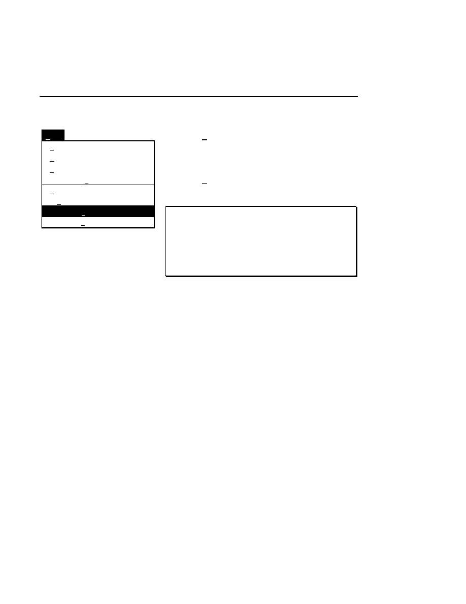
Image Window
Image Window - Goto Menu
2-25
Frame...
Tab
Last base
Base...
Goto
Ctrl+End
Next Ambiguity
Ctrl+G
1/4 page down
Tab
Ctrl+A
Shift+PgDn
First base
Ctrl+Home
1/4 page up
Shift+PgUp
1/4 page up
Shift + PgUp
Scrolls the image 1/4 frame up.
1/4 page down
Shift + PgDn
Scrolls the image 1/4 frame down.
Keyboard Shortcuts: The Home, End, Page Up, and
Page Down keys also function in the Image window as
follows: Home - image moves to beginning of file; End -
image moves to end of file; Page Up - image moves 3/4 of
a frame up; Page Down - image moves 3/4 of a frame
down.
Section 2
2-26
Image Window - View Menu
View Menu
View
✓
Show Band Markers
Wide Band Markers
Ctrl+R
✓
Black on White
Single sample
White on Black
Ctrl+Y
Pseudo Color
The View menu contains commands that affect how the image
is displayed in the Image window.
Show Band Markers
Ctrl + R
The Show Band Markers command toggles band markers atop
sequenced bases ON and OFF. A check mark next to the
menu item indicates that the markers are ON.
Wide Band Markers
Select Wide Band Markers to toggle the band markers on the
image between wide and narrow. Narrow band markers are
useful for viewing and/or editing images where the bands are
small or closely spaced, and therefore may be obscured by the
wide band markers.
Single sample
After the lanes have been defined, this command reduces the
width of the Image window so that only the sample defined by
the lane markers is visible.
White on Black/Black on White
Ctrl + Y
Changes the image to appear as black bands on a white
background, or white bands on a black background. The way
that the image is displayed when opened is determined by the
current configuration file. Edit the configuration file if you
want to have the image displayed differently upon opening.

Image Window
Image Window - View Menu
2-27
Pseudo Color
Pseudo Color
remaps the greyscale pixels on the image to a
combination of red, blue, and green. Pixels with the highest
raw signal strength (the bands) are remapped with a high
percentage of red. Pixels with the lowest raw signal strength
(the background) receive a high percentage of blue, and those
with medium strength receive a high percentage of green.
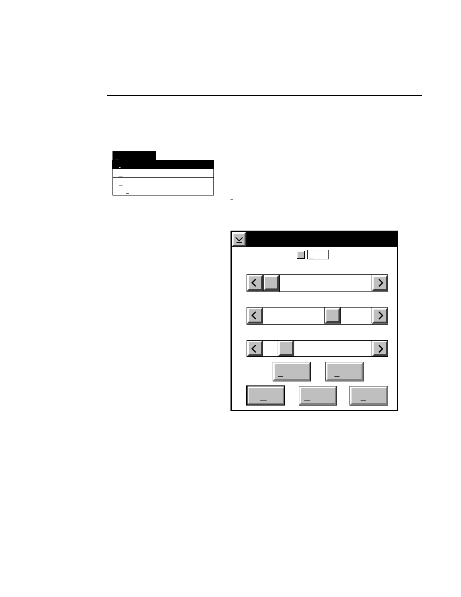
Section 2
2-28
Image Window - Enhancement Menu
Enhancement Menu
Bands
Background subtraction...
Smile correction...
Enhancement
Ctrl+S
Ctrl+N
Intensity adjustment...
Ctrl+I
The Enhancement menu contains four commands to alter the
appearance of the image.
Intensity adjustment...
Ctrl + I
Select Intensity Adjustment from the Enhancement menu to
open the Intensity Adjustment dialog box:
Intensity Adjustment
Brightness 60
Show
Contrast 20
Cancel
OK
Help
Default
Reset
Sensitivity 0
✔
The Intensity Adjustment dialog box lets you change how the
image is displayed in the Image window, using the sensitivity,
brightness and contrast slider bars. When the sliders are
moved, the 'Show' check box is enabled, and the changes are
Image Window
Image Window - Enhancement Menu
2-29
automatically displayed in the Image window, allowing
interactive adjustments.
Changes to the displayed image affect only the
appearance of the image and not the original image file.
The
Sensitivity
slider bar changes the lookup table that is
applied to the image when data are collected in 16-bit mode.
These lookup tables remap the 16-bit data down to the number
of bits that the monitor is able to display. Values from 0 to 7
can be applied to the data; experiment by moving the slider bar
until the image appears as desired. This slider bar will be
greyed out when data are collected in 8-bit mode.
The
Brightness
slider bar changes the value of the average
background intensity. Moving the slider to the left (or clicking
the left arrow button) reduces the background intensity. As
the brightness value displayed above the slider bar approaches
zero, the average background gets darker (when viewing white
bands on a black background). Moving the slider to the right
increases the average background intensity, making the image
background appear lighter as the brightness value approaches
100.
The
Contrast
slider bar changes the intensity of the
background noise. Moving the slider to the left (or clicking
the left arrow button) reduces the background noise of the
image. As the contrast number displayed above the slider bar
approaches zero, the background of the image will appear less
grainy and more uniform. This also results in the bands being
less distinct. Moving the slider to the right increases the
background noise of the image, making the background more
grainy and the bands somewhat easier to distinguish.
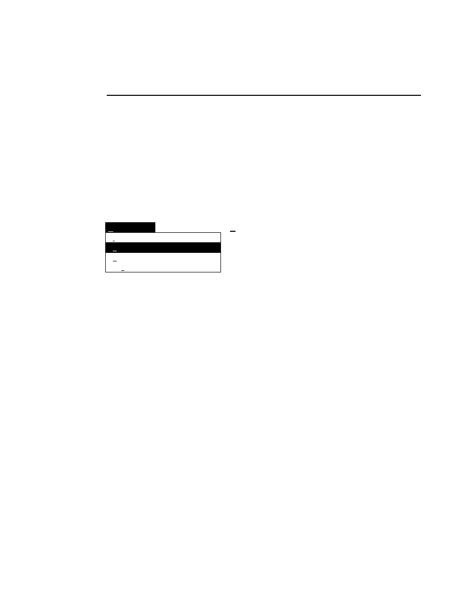
Section 2
2-30
Image Window - Enhancement Menu
The
Show
check box toggles between an altered intensity
setting and the default intensity setting when checked and
unchecked. The default intensity values are 50 for both
brightness and contrast. The Show check box is automatically
checked when either of the brightness or contrast sliders are
moved. The slider positions do not change when the 'Show'
check box is deselected, but the image intensity reverts back to
the default values.
Bands
Background subtraction...
Enhancement
Intensity adjustment...
Ctrl + I
Ctrl + N
Smile correction...
Ctrl + S
Smile Correction...
Ctrl + S
A “smile” is a band distortion that occurs as DNA strands
increase in length, and is usually caused by temperature
differences across the gel. A punctured loading well can also
cause a similar anomalous band shape later on in the run.
These anomalies are similar to smears, in that they are
generally a problem only near the end of the run.
Image Analysis can help to realign distorted areas of the
image. During Autosequencing, smiles are corrected
automatically as sequencing progresses. After auto
sequencing is complete, the smile corrections are retained with
the sample. During Manual or Semi-Automatic sequencing,
the Smile Correction dialog is used to correct image
distortions.
When you open the Smile Correction dialog box the 'Show'
check box is always checked, and all smile corrections are
shown. If you want to compare the corrected image with the
uncorrected image, deselect the 'Show' check box.
Smile corrections can be performed at numerous locations
throughout the sample. The corrections are additive, so if the
image has a smile that gets progressively worse you can add
more correction as you progress through the image.
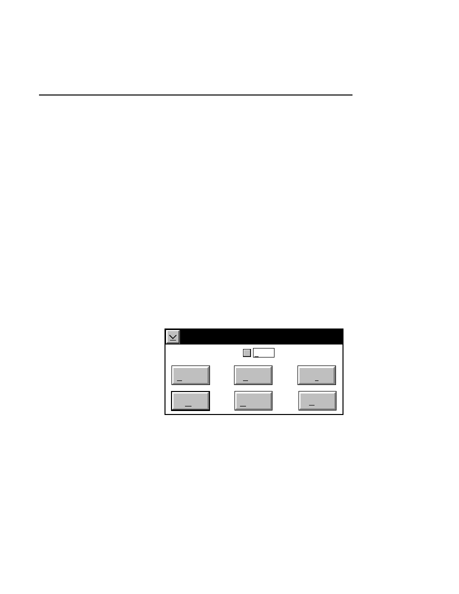
Image Window
Image Window - Enhancement Menu
2-31
It is important to understand how smile corrections are
displayed. Since it is not possible to display multiple
corrections in the same frame of the image window, it is
necessary to use an arbitrary convention for deciding which
correction to display. By convention, the Image Analysis
software first looks for smile corrections that are below the
middle of the image window. If there are no new corrections
in that portion of the window, it uses the last defined
correction (if any). In other words, it uses the last correction
below the middle of the image window, regardless of whether
the correction is 10 pixels or 10 frames below the center of the
window.
If a smile correction starting point is encountered below the
middle of the image window, that correction is used to render
the image. If there are multiple corrections encountered, the
one closest to the middle of the image is used. This can result
in not being able to see an existing correction when the image
is in a certain position.
Smile Correction
Show
Cancel
OK
Help
Define
Reset
Clear
✔
Using the
Clear
button is similar to defining a new correction,
but it resets the image in the defined region (see Step 3 below)
so that the total shift is zero pixels. Since the
Clear
button is
like defining a new correction, this means that if there are any

Section 2
2-32
Image Window - Enhancement Menu
smile corrections above the point where the corrections were
cleared, those corrections will still be in effect when that
portion of the image is displayed. In other words, the
Clear
button does not necessarily clear all corrections to the end of
the file, nor does it clear any corrections that are below the
middle of the image when the
Clear
button is pressed.
The
Reset
button removes any shift defined since the Smile
Correction dialog box was opened, and also deletes the shift
markers (the vertical lines that define the shift region, and the
horizontal trisected line, as described below in Step 4) so that
they can be redefined. The
Reset
button does not remove any
shift defined during previous smile correction operations.
Smile Correction Example
The following exercise shows how the smile correction
function is used. In the graphical representation below, there
is an area of the 'C' lane that is shifted upward at the right edge
of the lane. Although the appearance of the bands could also
be due to a downward shift at the left edge of the lane, moving
the left edge of the bands upward would result in the bands
being too close to the ones above them. Moving the right edge
downward will preserve the proper band spacing.
1.
Select
Smile correction
from the
Enhancement
menu.
The Smile correction dialog box appears.
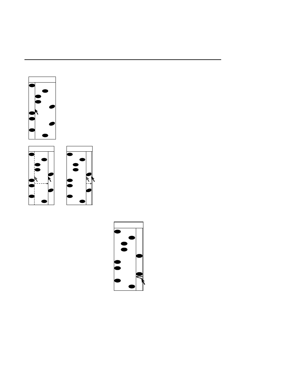
Image Window
Image Window - Enhancement Menu
2-33
A T G C
A T G C
A T G C
2.
Select
Define
. A vertical line appears in the image
window.
3
.
Defining the area for correction is similar to the method
employed when defining lanes:
Drag the marker to the left edge of the area of the image
to be shifted, click, hold, and move to the right edge of
the area to be shifted. Release the mouse button. This
defines the left and right boundaries of the area to be
shifted. The new shift point is at the middle of the Image
window and all image data above that point is shifted.
4
.
Define a horizontal starting point for the correction.
Click the pointer inside the lane, at the beginning point of
the area to be shifted. A trisected line appears.
5
.
The trisected line is used to shift the defined area up or
down, depending upon the direction in which the image
will be shifted. Dragging the right or left portion of the
line shifts the corresponding edge of the image up or
down. Dragging the center portion of the line shifts the
entire image within the defined area up or down.
A T G C
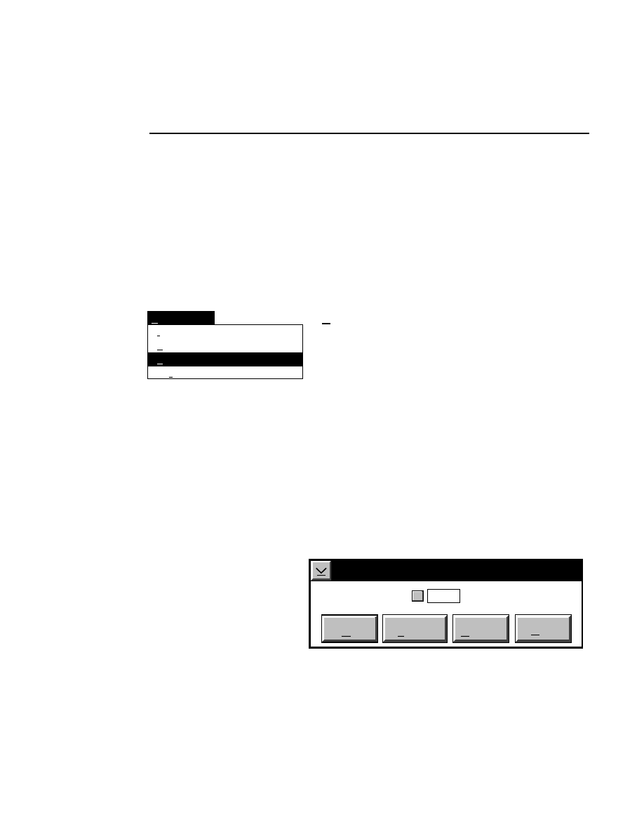
Section 2
2-34
Image Window - Enhancement Menu
A smile correction can be applied to several portions of the
image file concurrently; the shift will be retained at these
locations as the image is scrolled. There is a limit of 128
vertical lines (pixels) of shift over the entire image, however.
To view the uncorrected image again, deselect the 'Show'
check box.
Bands
Smile correction...
Enhancement
Intensity adjustment...
Ctrl + I
Ctrl + S
Ctrl + N
Background subtraction...
Background Subtraction...
Background Subtraction calculates the average intensity of the
background in the defined lanes, and then subtracts this
average from all of the pixels in the image. The effect is a
reduction in the brightness of both the bands and the
background. Because the signal strength of the bands is much
stronger than the background, the bands appear brighter in
relation to the background.
When Background Subtraction is enabled, only the displayed
image is changed; the original image file is not changed, nor is
the calculated background average value saved when the file is
closed.
When Background Subtraction is selected, the Background
Subtraction dialog box is displayed:
Background Subtraction
Show
Cancel
OK
Help
Calculate
✔
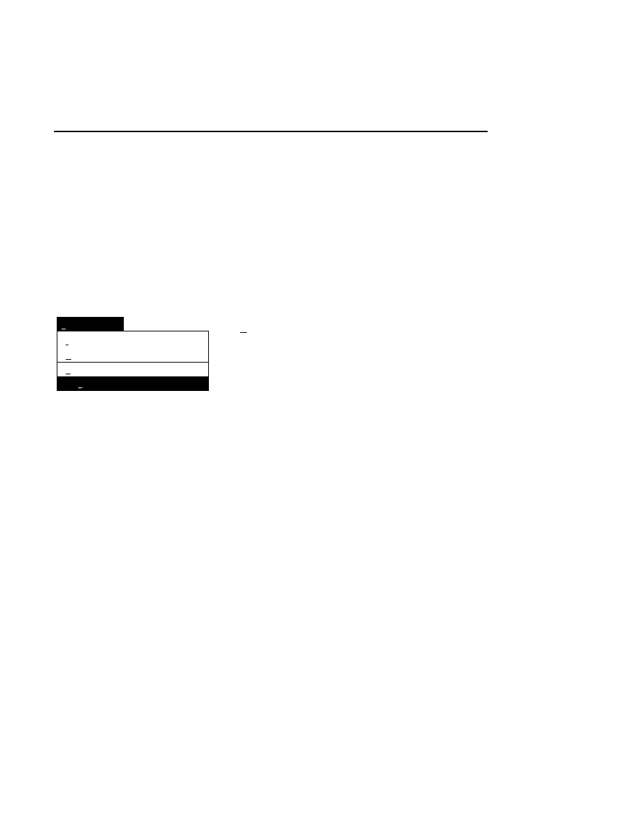
Image Window
Image Window - Enhancement Menu
2-35
Press
Calculate
to compute the average background intensity
in the defined lanes, and subtract it from the image. The
'Show' check box is automatically enabled when
Calculate
is
chosen.
After Background Subtraction is applied to the image, the
video image can be returned to normal by unchecking the
'Show' check box.
Enhancement
Ctrl+I
Ctrl+S
Ctrl+N
Intensity adjustment...
Smile correction...
Background subtraction...
Bands
Bands
Ctrl + N
The Bands menu choice is a normalizing function that
performs an image enhancement on the image inside the
sample lanes, which results in all bands having about the same
brightness level. When the Bands enhancement is turned on,
the image will look like a high contrast image in which the
weak bands have been boosted in brightness. The background
will also become more uniform and noticeably darker.
If the lanes defined in the sample are too broad, the Bands
function will not work properly, in which case an error
message will be displayed.
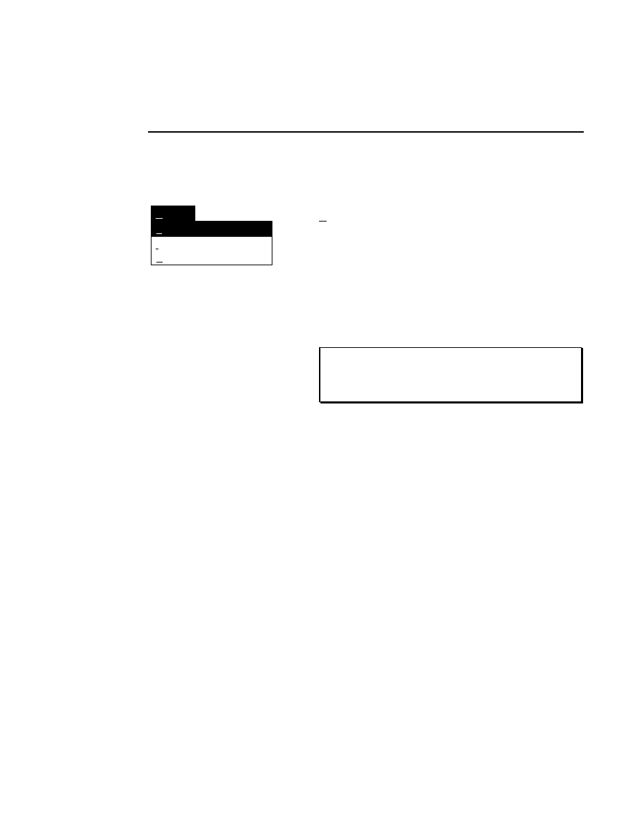
Section 2
2-36
Image Window - Options Menu
Options Menu
Options
Extract sample image...
Image Remarks...
Sample Remarks...
Extract sample image...
This menu item is available only after sample lanes have been
defined (see Lane Definition). The Extract Sample Image
function exports the image data within the sample lanes to a
new file. This can conserve disk space if, for example, the
image contains only a few samples. Similarly, if the image
contains multiple replications of a single sample, it may be
desirable to save only the best sample, rather than the entire
image.
NOTE: Portions of the image can also be extracted using
Base ImagIR Image Manipulation and saved in LI-COR
Image, TIFF, and other file formats.
When this menu item is selected, the Extract Sample Image
dialog box is displayed. Type the file name for the new image
file in the 'File name' field. Change the directory to which the
file will be saved using the Directories list box, or click on
Create Directory
to make a new directory. Press
Save as
to
extract the image to the new file.
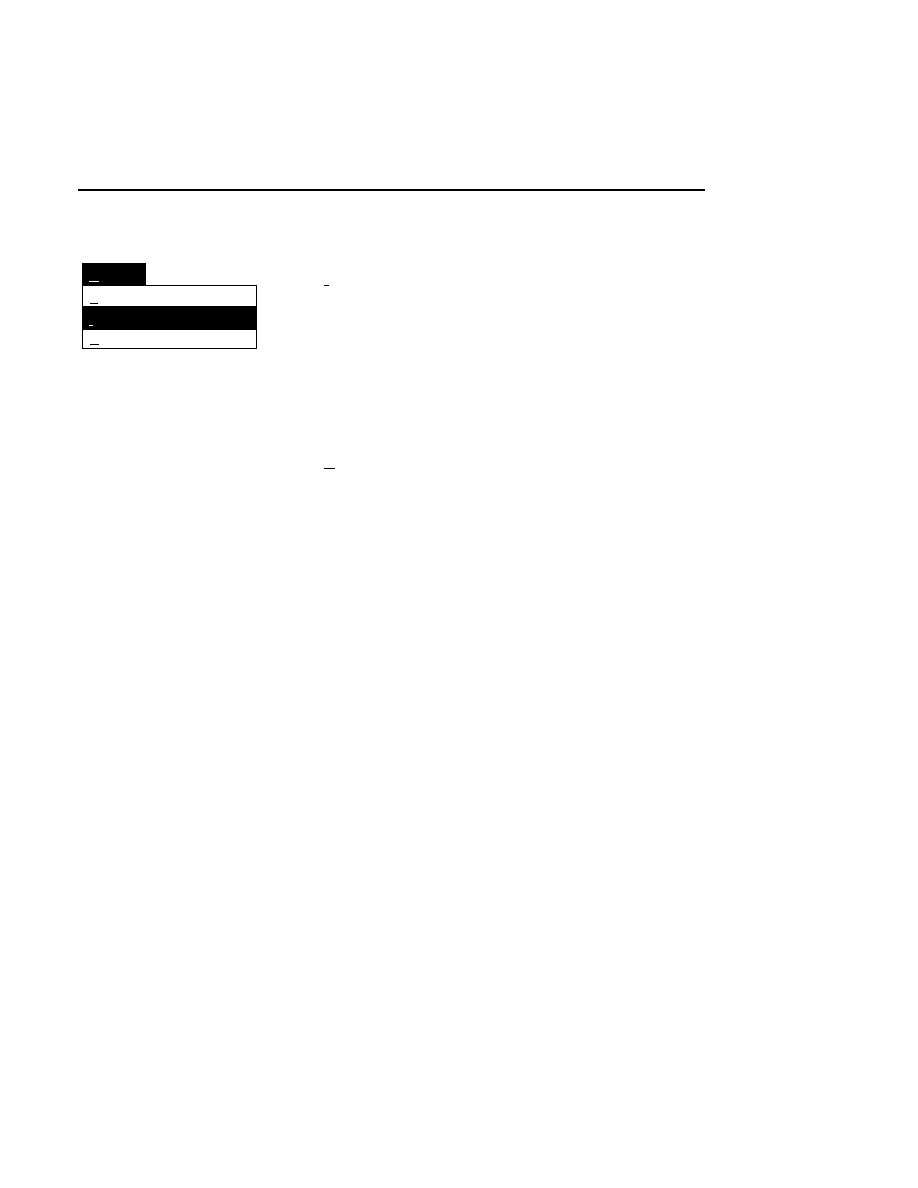
Image Window
Image Window - Options Menu
2-37
Options
Extract sample image...
Image Remarks...
Sample Remarks...
Image Remarks...
Opens the Image Remarks dialog box. The remarks shown
were entered during Data Collection when the image file was
created. The remarks can be selected and copied to the
clipboard, where they can be pasted into another application,
such as the Sample Notepad. The remarks can not, however,
be edited here.
Sample Remarks...
Select Sample Remarks to display the remarks entered into the
Auto Sequence Setup Samples page.
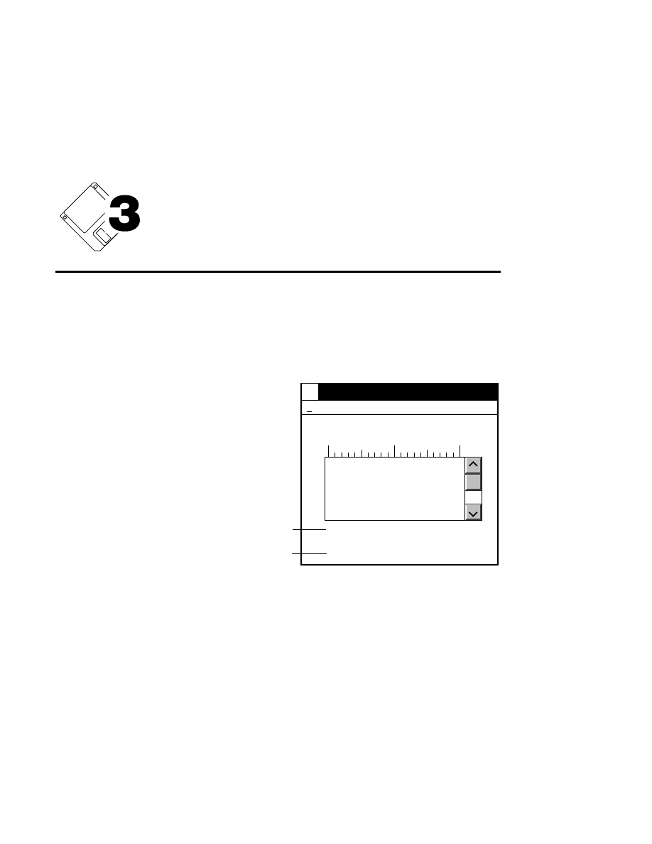
Sequence Window
3-1
Sequence
Window
The Sequence window is one of the two areas in which
sequence data are displayed. Data are also displayed vertically
along the left edge of the Image window. The Sequence
window can be minimized, maximized to fill the Image
Analysis window, moved, and sized up or down by dragging
the border(s).
Cursor: 530
Selection: None
Last Base: 530
1
21
41
61
81
10
20
CGCGGCAGTGCAAGCTTATC
GATGATAAGCTGTCAAACAT
GGCCTGTCGCTTGCGGTATT
CGGAATCTTGCACGCCCTCG
CTCAAGCCTTCGTCACTGGT
Current cursor position
# of last base marked
Sequence
Edit
A T
G
C
C
G
T
A
A
T
C
G
A
C
The sequence data in the Sequence window are identical to,
and interactive with the data shown in the Image window.
Bases marked or deleted in the Image window are marked or
deleted in the Sequence window, and vice versa.
The Edit menu contains commands to copy, delete, or find
sequence information in the Sequence window.
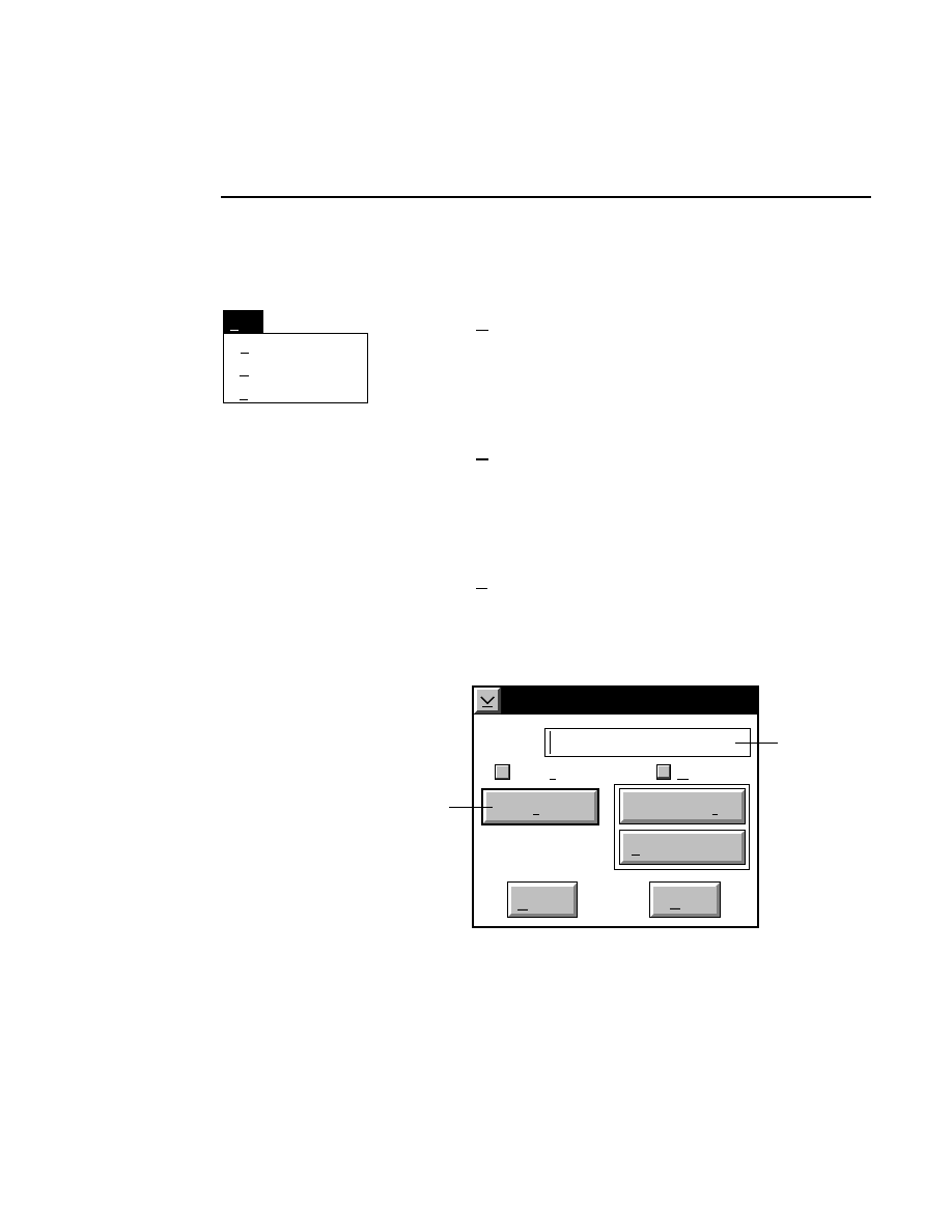
Section 3
3-2
Sequence Window - Edit Menu
Edit Menu
Find...
Delete
Edit
Copy
Ctrl+F
Ctrl+Ins
Copy
Ctrl + Ins
Copies selected sequence text to the clipboard, where it can be
pasted into other applications that support the OS/2 clipboard,
such as the Sample Notepad.
Delete
Removes selected sequence information. The sequence data
are not copied to the clipboard, and can not be retrieved after
the Delete command is performed.
Find...
Ctrl + F
The Find command searches the sequence data for a base, a
series of bases, or for ambiguities. Selecting
Find
opens the
Find dialog box:
Find
Base(s):
Cancel
Help
Case sensitive
Wrap
Find ambiguity
Find base(s)
Show IUPAC
Enter text to
search for here
Press here to start search
✔

Sequence Window
Sequence Window - Edit Menu
3-3
The
Base(s)
field is used to enter the text for the base(s) to
locate. The base(s), if found, will be highlighted in the
Sequence window.
In the
Find
dialog box:
Press
to...
Find base(s)
Find the first occurrence of the text
entered in the Base(s) field. The
search begins at the cursor location.
When the end of the sequence data is
reached, the search will begin again at
the first base (if the 'Wrap' check box
is enabled). Click on this button again
to find subsequent occurrences of the
base(s).
Find ambiguity
Find ambiguities in the sequence,
regardless of the ambiguity code used.
The search begins at the cursor
location. When the end of the
sequence data is reached, the search
will begin again at the first base (if the
'Wrap' check box is enabled). To
search for a specific ambiguity code,
enter the appropriate code in the
Base(s) field, and press the Find
base(s) button. Click on this button
again to find subsequent occurrences
of ambiguities.
Show IUPAC
Display the modified IUPAC Ambi-
guity Code list.

Configuration Notebook
4-1
Configuration
Notebook
General Overview
The Configuration notebook window represents a file that can
be saved with a unique set of preferences for individual users
or various sequencing protocols.
This can be very useful, if, for example, a user prefers to use
certain image enhancements (i.e., display style, image size).
The user can recall a configuration file and apply it globally to
the Image Analysis program, rather than changing each
parameter individually.
A default configuration file (
DEFAULT.ANL)
is in the
DNA4200 directory. This file contains default values for
image enhancements, such as Image Display Style, as well as
for other parameters used during sequencing. The
DEFAULT.ANL
file can be modified as desired and renamed
as a new file, or saved as the new default configuration file.
Note that the Image Analysis Configuration notebook can be
run as a separate application, as well. This can be useful for
modifying or creating configuration files without opening the
Image Analysis program. See the description later in this
section at Creating a Configuration Program Object.
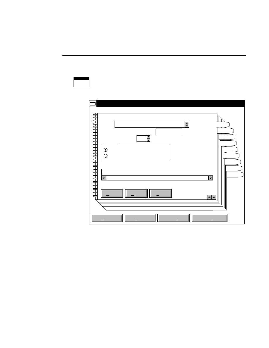
Section 4
4-2
Configuration Notebook
Cfg
Configuration
The Configuration notebook normally appears as an icon in the
Image Analysis window. Double-click on the icon to open the
Configuration notebook.
Default
Reset
Save as
Save
Open
Save as default
Help
Configuration - DEFAULT.ANL
Loading Information
Comb: 32-Well Rectangular
Lane Order (A,T,G,C,'-'(empty)): ATGC
Number of Samples: 4
Formats
No Selected Lanes
Comb Loading: A,T,G,C,X (nonsequence load),'-'(empty lane)
ATGC_ATGC_ATGC_ATGC
Standard Loading Format
Mutation Analysis Loading Format
Samples
Path
Image
Seq
Open
Notes
Reports
Autosave
Load
The Configuration window title bar displays the path and
filename of the active configuration file. The
DEFAULT.ANL
file is loaded each time Image Analysis is opened.
Click on any of the notebook tabs to open a page related to
that tab. You can also click on the right or left arrow buttons
in the lower righthand corner of each page to move forward or
backward through the notebook pages.
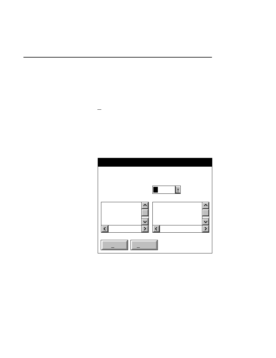
Configuration Notebook
Configuration Notebook
4-3
The Configuration notebook contains an Open, Save, Save as,
and Save as Default button. In addition, each individual page
contains a Default, Reset, and Help button.
Open
Loads a configuration file into the Configuration window.
Selecting
Open
brings up the Open dialog box. Click on the
desired configuration file in the 'Files' list box and press
OK
,
or
double-click on the desired configuration file. The files
shown in the list box are those present in the active directory,
shown in the 'File' text field. Use the Directories list box to
change directories.
OK
Cancel
Configuration - Open
File: C:\DNA4200\Default.ANL
..
anl
col
img
Default.ANL
SHARK48.ANL
SHARK64.ANL
SQUARE32.ANL
Drives:
C:
Directories:
Files:
Section 4
4-4
Configuration Notebook
Save
Saves the current configuration parameters to the active con-
figuration file.
Save as...
Saves the current configuration parameters to a new file,
specified in the Save as dialog box. Enter the complete path
and name of the new configuration file in the 'File' text entry
field. If no path is specified, the file will be saved to the
directory shown at 'Drives'. Select a different directory from
the Directories list box if necessary.
NOTE: Entering
DEFAULT.ANL
for the File name is
not allowed.
Save as default
Saves the current configuration parameters to the default
configuration file
DEFAULT.ANL
. This function will
overwrite the existing
DEFAULT.ANL
file. When selected,
you are prompted with the Save Configuration message box.
Select
Yes
to overwrite the
DEFAULT.ANL
configuration file.
Default
Resets the parameters in the notebook page to default values.
Reset
Resets the parameters in the current notebook page to those
present when the page was opened.
Configuration Notebook
Configuration Notebook - Load Page
4-5
Load Notebook Page
Default
Reset
Save as
Save
Open
Save as default
Help
Configuration - DEFAULT.ANL
Loading Information
Comb: 32-Well Rectangular
Lane Order (A,T,G,C,'-'(empty)): ATGC
Number of Samples: 4
Formats
No Selected Lanes
Comb Loading: A,T,G,C,X (nonsequence load),'-'(empty lane)
ATGC_ATGC_ATGC_ATGC
Standard Loading Format
Mutation Analysis Loading Format
Samples
Path
Image
Seq
Open
Notes
Reports
Autosave
Load
The Load Notebook page is where you define the default
loading order of the samples in preparation for sequencing all
samples automatically, using the Auto All Samples menu
choice. See Image Window Section 2 (Autosequence All
function) for a complete description of the Load Notebook
page.
Section 4
4-6
Configuration Notebook - Samples Page
Samples Notebook Page
Default
Reset
Save as
Save
Open
Save as default
Help
Configuration - DEFAULT.ANL
No. Sample Name Remarks
1 SAMPLE1
2 SAMPLE2
3 SAMPLE3
4 SAMPLE4
Sample Name(s): SAMPLE
Samples
Samples
Path
Image
Seq
Open
Notes
Reports
Autosave
Load
Create Report Files Create SCF Files
✔
The Samples Notebook page is where the default sample file
name is entered, as well as any remarks appropriate to each
sample file.
The number of sample names displayed is determined by the
number of samples entered in the Load Notebook page.

Configuration Notebook
Configuration Notebook - Samples Page
4-7
In the 'Sample Name(s)' field, enter the name for the sample
file(s). This name will automatically be appended with a one-
or two-digit number (1, 2, 3, ... 10, 11 etc.) and a .SMP file
extension. For example, if you enter 'Test' for the Sample
Name, and have defined 8 samples in the Load Notebook
page, you will see 8 sample files listed, entitled Test1, Test2,...
Test8. You can manually edit any sample name or remarks by
selecting the text in the field and typing the new text.
File reports and/or SCF files can be generated automatically
for each sample sequenced using the Auto Sequence All
function. The parameters that will comprise the File Report
(including the default file report extenstion) are derived from
the Reports Notebook pages. To automatically generate report
files for each sample, enable the ‘Create Report Files’ check
box. To generate SCF files, enable the 'Create SCF Files'
check box.
Section 4
4-8
Configuration Notebook - Path Page
Path Notebook Page
Default
Reset
Save as
Save
Open
Save as default
Help
Configuration - DEFAULT.ANL
Data Directory
..
anl
col
img
Current: C:\DNA4200
New: C:\DNA4200
Drives:
C:
Directories:
Samples
Path
Image
Seq
Open
Notes
Reports
Autosave
Load
Specifies the default path to which new Samples and all
associated files are saved. Once a Sample file has been
created, changing the path in configuration has no effect on
that particular Sample file. Use the Drives and Directories list
boxes to change the path.
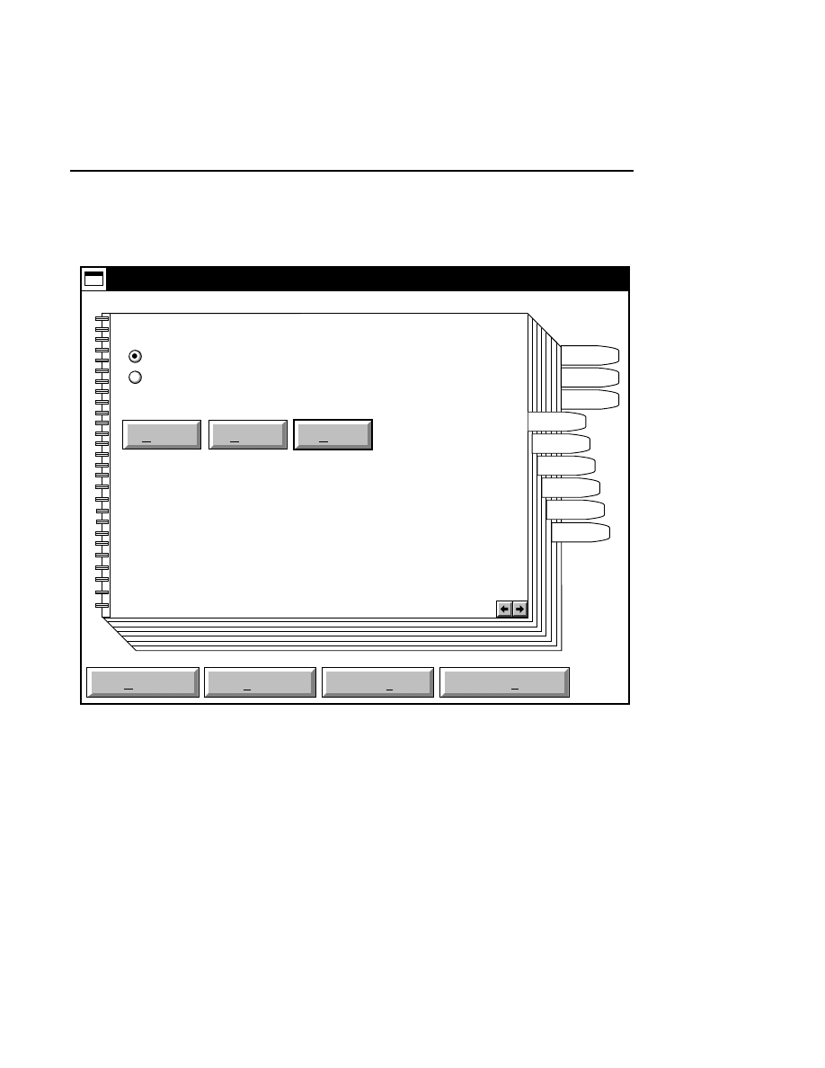
Configuration Notebook
Configuration Notebook - Image Page
4-9
Image Notebook Page
Default
Reset
Save as
Save
Open
Save as default
Help
Configuration - DEFAULT.ANL
Image Display Style
Black bands on white background
White bands on black background
Samples
Path
Image
Seq
Open
Notes
Reports
Autosave
Load
An image can be displayed in either of two ways by selecting
the appropriate radio button; as a high contrast image with
white bands on a black background, or as an autoradiogram-
like image with black bands on a white background.

Section 4
4-10
Configuration Notebook - Sequence Page
Sequence Notebook Page
Default
Reset
Save as
Save
Open
Save as default
Help
Configuration - DEFAULT.ANL
Sequence Settings
Band Spacing 12
Auto Stop Number of Bases 1100
Ambiguities Symbol
Base Calling Mode
Ambiguities Case
Modified IUPAC
'N' for all
'X' for all
Upper
Lower
Samples
Path
Image
Seq
Open
Notes
Reports
Autosave
Load
Standard
Heterozygous
The Sequence Notebook page contains sequence settings that
serve as initial values when sequencing is enabled.
Band spacing
is the vertical distance (in pixels) the
sequencing cursor moves during sequencing. This serves as
an initial value only, and is the spacing that will be in effect

Configuration Notebook
Configuration Notebook - Sequence Page
4-11
when Image Analysis is opened. Type in the new value for the
band spacing, if desired.
The
Auto Stop Number of Bases
box allows you to set a
default value for the number of bases that will be sequenced
during automatic sequencing of single or multiple samples,
when the 'Number of Bases' radio button is selected in the
Automatic Sequence-Single Sample or Auto Sequence All
Defined Samples dialog boxes.
The symbol set chosen in the
Ambiguities Symbol
box
determines the default ambiguity symbol set used when you
open a new sample and sequence in manual or semi-automatic
modes. See description at Ambiguities (Image window -
Sequence menu).
Select the 'Upper' or 'Lower' case radio buttons to mark
ambiguities with either upper- or lowercase letters only.
The Base Calling Mode radio buttons determine the algorithm
that is used during base calling. When
Heterozygous
base
calling is enabled, the software looks specifically for
heterozygotes (more ambiguities). In other words, the
software is more sensitive to ambiguities, for more accurate
mutation detection.
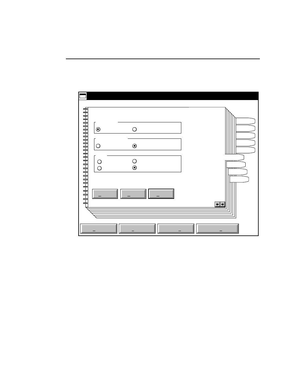
Section 4
4-12
Configuration Notebook - Open Page
Open Notebook Page
Default
Reset
Save as
Save
Open
Save as default
Help
Configuration - DEFAULT.ANL
'Open' Options
Image Size
Single Sample Maximized
Goto
Tab
First frame
Samples
Path
Image
Seq
Open
Notes
Reports
Autosave
Load
First base
Last base
Sequence mode
Manual/Edit Semi-automatic
When the Image Analysis program is opened, there are several
options that can be enabled automatically.
The
Image Size
radio buttons determine whether the whole
image or only the current sample will be displayed in the
Image window when a Sample file is re-opened. If the Single
Sample button is enabled, and Open Sample is chosen from the
File menu of the Image Analysis window, the Image window

Configuration Notebook
Configuration Notebook - Open Page
4-13
will display only the four lanes of that sample. If the
Maximized radio button is enabled, the Image window will
display the entire image.
The
Sequence Mode
determines whether Manual or Semi-
automatic sequencing will be enabled when a Sample file is
opened.
The
Goto
radio buttons determine which image frame is
displayed when a Sample file is opened. Select the Tab radio
button to open the image at the tab set during Data Collection.
Select First frame to open the image at its first page of
collected data. Select First base or Last base to open the
image and display the first or last base sequenced in the
Sample file.
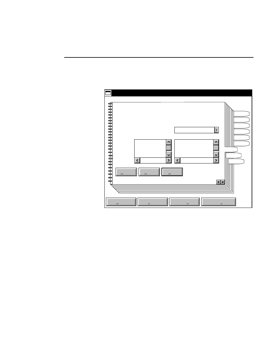
Section 4
4-14
Configuration Notebook - Notes Page
Notes Notebook Page
Default
Reset
Save as
Save
Open
Save as default
Help
Configuration - DEFAULT.ANL
Samples
Path
Image
Seq
Open
Notes
Reports
Autosave
Load
Sample Notepad Form
..
anl
col
img
Current: C:
New: C:
Drives:
C:
Directories:
Files:
The Sample Notepad form used when Image Analysis is
opened can be selected from the Files list box. Use the Drives
and/or Directories list boxes to change the path.
Notepad form files can be created with the OS/2 System
Editor. Save the file as Plain Text, with a .SNT file extension.
The SAMPLE.SNT file included with the Base ImagIR
software is an example of a typical notepad form file. This file
can be modified and saved as a new form file, if desired.
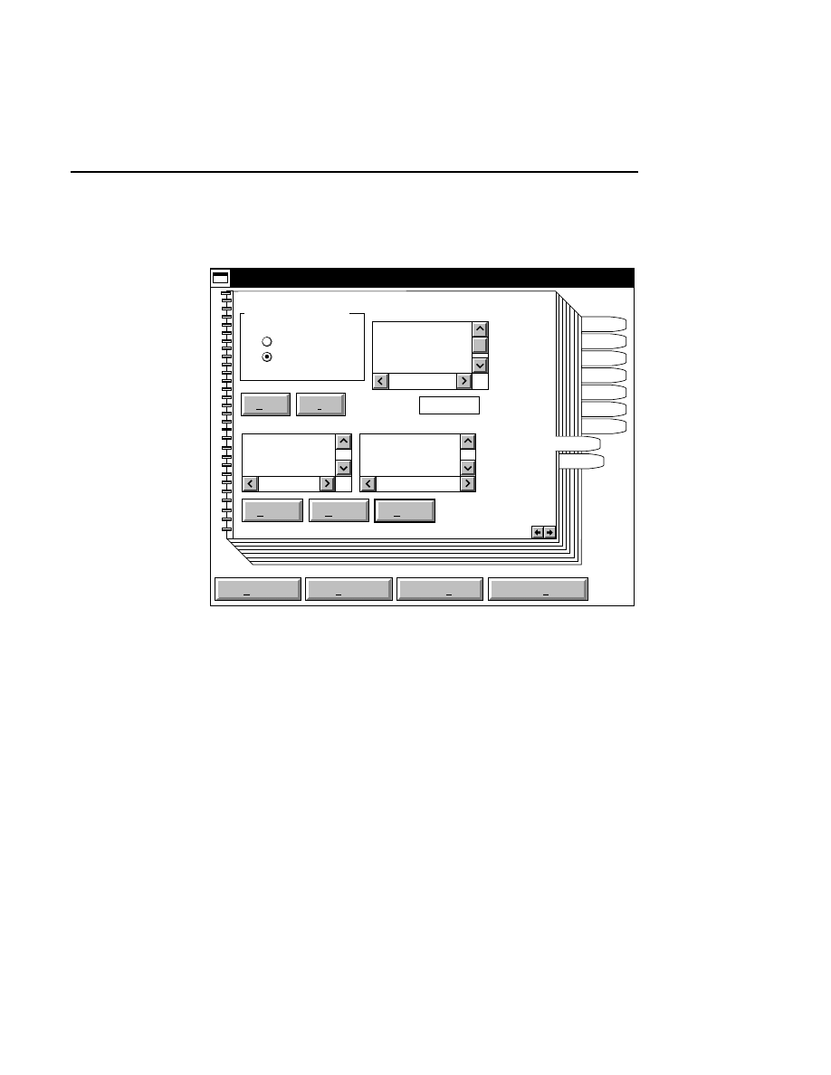
Configuration Notebook
Configuration Notebook - Reports Page
4-15
Reports Notebook Page 1
Default
New
Delete
Reset
Save as
Save
Open
Save as default
Help
Configuration - DEFAULT.ANL
Samples
Path
Image
Seq
Open
Notes
Autosave
Reports
Load
Report Formats
Modifying Report Type:
Options
Delimiter: ..
Order of File Report
Page 1 of 2
SN Sample Notepad
S Sequence
DL Delimiter
FF Form Feed
SN
..
S
Order of Print Report
Print Report
File Report
Sequence data, Image Remarks, the Image Notepad, Sample
Notepad, and Log Notepad can be printed to the system printer
in a user-specified format. The Reports Notebook page 1
allows you to configure the default report format.
Select the report type to be modified by choosing a radio
button under 'Modifying Report Type'.
The parameters available for export (shown in the Options list
box) are:
●
Sample Notepad (SN) - Image Analysis notes.

Section 4
4-16
Configuration Notebook - Reports Page
●
Sequence (S) - sequence data.
●
Delimiter (DL) - character(s) which separate groups
of information such as marking the beginning or end
of sequence data. Data analysis programs generally
recognize a unique delimiter, such as (..) or ($).
●
Form Feed (FF) - sends a form feed so that
information that follows appears on a new page.
Some printers require a form feed at the end of the
Order list to properly send the document.
●
Image Notepad (IN) - Image Notepad notes.
●
Image Remarks (IR) - notes made in the Remarks
field of the 'New' dialog box in Data Collection.
●
Image Log (IL) - electrophoresis parameters
recorded in the Log Notepad during Data Collection.
The Order list box shows the report format. In the figure
above, the File Report is set to export the Sample Notepad
(SN), a Delimiter (••), and the Sequence information (S).
Click on the New button to clear all entries from the Order list
box. Click on the Delete button to remove only the selected
parameter from the Order list box.
Double-click on the parameters in the Options list box to add
them to the Order list box. Parameters can be inserted at any
position in the Order list box. If a parameter is highlighted in
the Order list box, new parameters will be added ahead of the
selected one. If no parameters are highlighted, new
parameters will be added to the end of the list.
Change the Delimiter in the text entry field by selecting it and
typing in the new text.
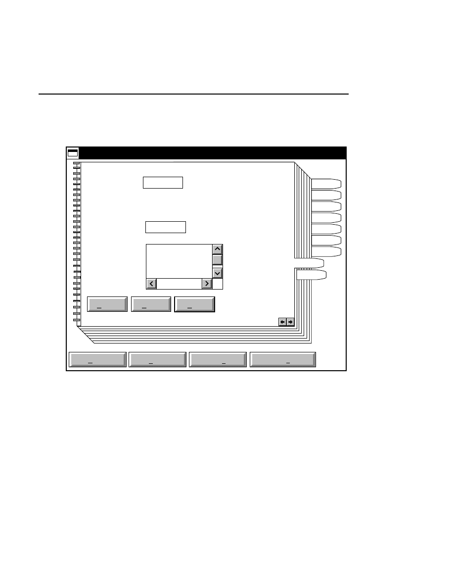
Configuration Notebook
Configuration Notebook - Reports Page
4-17
Reports Notebook Page 2
Default
Reset
Save as
Save
Open
Save as default
Help
Configuration - DEFAULT.ANL
Samples
Path
Image
Seq
Open
Notes
Autosave
Reports
Load
Report Destination
Default Extension: .rpt
Directories:
Drives:
C:
Current: C:
New: C:
Page 2 of 2
..
anl
col
img
The Reports Notebook page 2 is used to set the default file
report extension and the path to which the file report will be
sent. The Order list from Reports Notebook page 1 is used by
the File command on the Report menu of the Image Analysis
window to transfer the data to an ASCII data file.
You can change the default file extension that is added to the
report name, by entering the text in the Default Extension
field. The LI-COR default file report extension is .rpt.
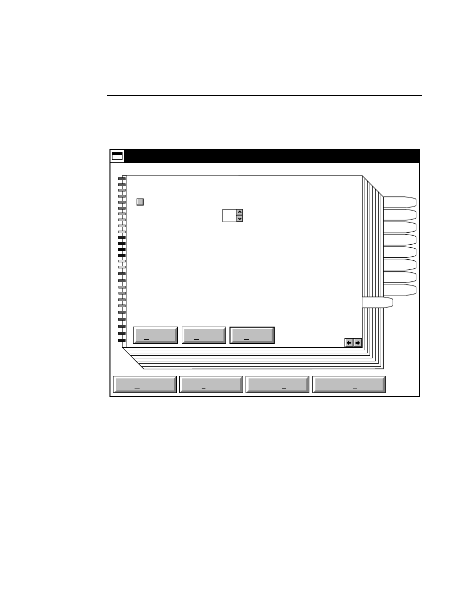
Section 4
4-18
Configuration Notebook - Autosave Page
Autosave Notebook Page
Default
Reset
Save as
Save
Open
Save as default
Help
Configuration - DEFAULT.ANL
Autosave
Autosave
Auto save time in minutes 1
Samples
Path
Image
Seq
Open
Notes
Reports
Autosave
Load
✔
Enter the interval (in minutes) that will appear in the Autosave
dialog box when Autosave is selected from the File menu in
Image Analysis.
Deselect the check box to disable the Autosave feature.
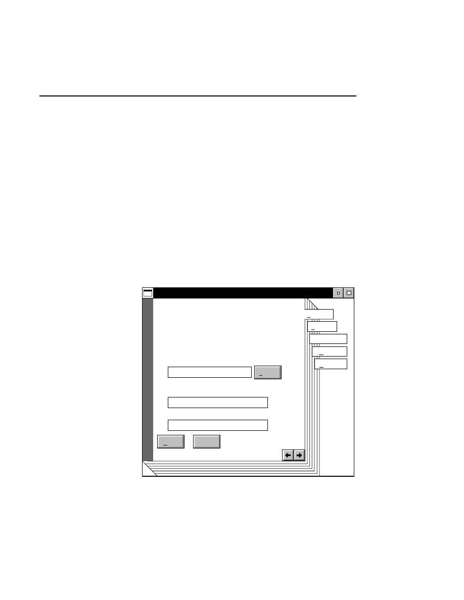
Configuration Notebook
Configuration Window
4-19
Creating a Configuration Program Object
If you would like to run the Image Analysis Configuration
window as a unique program, separate from the Image
Analysis program, you can create a program object on the
desktop, as described below.
■
To create a Configuration program object:
1
.
Double-click on the Templates folder icon (generally
found in the OS/2 System folder).
2
.
Drag a program template to another folder, or to the
desktop. The Program - Settings window appears.
Program - Settings
Required
Path and file name:
Optional
Parameters:
Working directory:
Program
Undo
Find...
Help
C:\DNA4200\ANLCFG.EXE
Session
Association
Window
General

Section 4
4-20
Configuration Window
3.
In the 'Path and file name' field enter:
C:\DNA4200\ANLCFG.EXE.
4.
Click on the
General
notebook tab, select the text in the
'Title' text field, and enter Image Analysis Configuration.
5.
Double-click on the system menu icon in the upper
lefthand corner of the window. Double-click on the new
program object to open the Image Analysis Configuration
window.
Message Window
5-1
Message
Window
The Message window displays system messages and records
Base ImagIR commands that were performed during an Image
Analysis session. In normal operation, the messages in the
Message window are not needed, nor are they saved.
However, they are occasionally useful in diagnosing system
problems.
Messages
i
Sample Notepad
6-1
Sample
Notepad
The Sample Notepad is a standard text editor that can be used
to record information during Image Analysis.
Sample Notepad
Edit Options
The Sample Notepad is automatically saved each time a new
sample file is created during Image Analysis. For example,
saving a sample file named
Test.smp
will automatically
create a Sample Notepad file called
Test.snt.
Subsequent
Save (or Autosave) operations performed on the sample file
will automatically update the Sample Notepad, as well.
Section 6
6-2
Sample Notepad - Edit Menu
Edit Menu
Find...
Delete
Edit
Copy
Ctrl+F
Ctrl+Ins
Cut
Shift+Del
Paste
Shift+Ins
Clear
Select all
Cut
Shift + Del
Deletes selected text, and places it in the clipboard, for later
retrieval (until another selection is cut or copied).
Copy
Ctrl + Ins
Copies selected text to the clipboard, without removing it from
the Sample Notepad.
Paste
Shift + Ins
Inserts text at the cursor position that was previously cut or
copied to the clipboard.
Clear
Replaces selected text with spaces. The text is overwritten
without copying it to the clipboard.
Sample Notepad
Sample Notepad - Edit Menu
6-3
Find...
Delete
Edit
Copy
Ctrl+F
Ctrl+Ins
Cut
Shift+Del
Paste
Shift+Ins
Select all
Clear
Delete
Removes selected text without copying it to the clipboard.
Find...
Ctrl + F
Find searches the Sample Notepad for user-specified text. The
Find dialog box opens:
Find
Find:
Change
Help
Case sensitive
Wrap
Change to:
Change All
Cancel
Find
Change, then Find
Enter text to search for here
Enter replacement text here
Press here to
begin search
✔
Enter the text to search for in the 'Find' field.
NOTE: To search for both upper- and lowercase
occurrences of the entered text, disable the 'Case sensitive'
check box.
If the 'Wrap' check box is enabled, the text search will begin at
the cursor location, continue to the end of the file, and then
Section 6
6-4
Sample Notepad - Edit Menu
begin again at the start of the file. If disabled, the file will
only be searched from the cursor location to the end of the file.
In the
Find
dialog box:
Press
to...
Find
Start the Find operation, which
searches the Sample Notepad for the
text in the 'Find' field.
Change, then Find
Change the text found in the above
operation to that entered in the 'Change
to' field, and then search for the next
occurrence of the 'Find' text.
Change
Change the text found, without
searching for subsequent occurrences
of the 'Find' text.
Change all
Change all occurrences of the 'Find'
text to that entered in the 'Change to'
text entry field.
Find...
Delete
Edit
Copy
Ctrl+F
Ctrl+Ins
Cut
Shift+Del
Paste
Shift+Ins
Select all
Clear
Select all
Selects all text within the Sample Notepad.
Sample Notepad
Sample Notepad - Options Menu
6-5
Options Menu
Options
Load form...
Print Ctrl+P
Wordwrap
Load form...
Opens the Load Notepad Form dialog box. From this dialog
box any notepad template with the file extension .SNT can be
loaded into the Sample Notepad for editing and/or review.
Load Notepad Form
Cancel
Help
Load
File:
Path: C:\DNA4200
Directories
..
[A:]
[B:]
[C:]
Files
SAMPLE.SNT
Enter Notepad filename here
and press Load, or ...
Double-click on the filename here
to quickly open the notepad form
NOTE: Loading a notepad form into the Sample
Notepad will clear all text currently in the Notepad.
There are two ways to open a notepad form:
1.
Type the path and filename of the form file into the 'File'
text entry field.
2
.
Locate the form file using the Directories and Files list
boxes, select it, and press
Load
, or
double-click on the
desired form file.
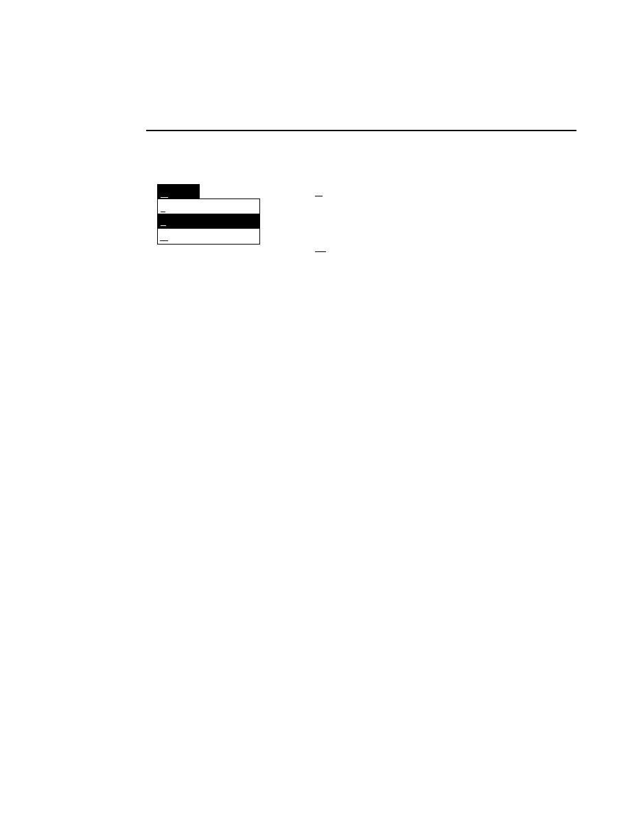
Section 6
6-6
Sample Notepad - Options Menu
Options
Load form...
Print Ctrl+P
Wordwrap
Ctrl + P
Prints the Sample Notepad on the system printer.
Wordwrap
If selected, causes the text in the Sample Notepad to wrap
according to the current size of the Sample Notepad window,
by forcing line breaks at the right edge of the window. If
unchecked, text will extend beyond the edge of the window,
and may not be visible without using the scroll bars.
Wordwrap affects only how the text is viewed; it does not
affect the actual data.

Image Manipulation
1-1
1
1
1
Image
Manipulation
Table of Contents

Section 1
1-2
Image Manipulation
Image Manipulation
Image Manipulation - Overview
1-3
Overview
The Base ImagIR™ Image Manipulation program can
manipulate LI-COR image files in a variety of ways,
including:
●
Cropping
●
Saving in alternate file formats (i.e., TIFF, EPS, etc.)
●
Sizing and scaling
●
Printing with image enhancements and/or printing resized
images
●
Printing sample files with sequence text
Double-click on the Image Manipulation icon in the Base
ImagIR folder to open the program. The Image Manipulation
window appears:
Base ImagIR Image Manipulation - C:\DNA4200\TEST.IMG
File Edit Goto Windows Options Help <BFM:BLN, TFM:TLN>

Section 1
1-4
Image Manipulation - Overview
The Image Manipulation window displays the image opened
from the File menu. There are six menus in the Image
Manipulation window; File, Edit, Goto, Windows, Options,
and Help. There is also a menu item that displays frame and
line numbers for the portion of the image displayed in the
window.
What is a Cropping Definition File?
When saving or printing an image, you may want to crop
(truncate) the image so that only a portion of it is saved or
printed. Cropping an image to eliminate empty frames,
unreadable frames, or bad samples can reduce the file size.
Cropping the file for printing allows you to print only the
sample(s) you want.
If you decide that you want to crop an image file, the first
thing to do is define the portion of the image to be cropped.
This is done by selecting Crop Definition from the Edit menu.
In the Crop Definition dialog box, the crop area is defined by
dragging horizontal and vertical markers onto the image, or by
entering the frame, line and column numbers for the crop
definition. These parameters can be saved as a crop definition
file, which is given the file extension .CRP. When this
definition file is reopened by selecting
Open Cropped
Definition
from the File menu, the image file that was cropped
is recalled to the window, and the cropping parameters and
markers appear in the Cropping Definition dialog box.
Keep in mind that the normal image window size (one frame
of data) is 512 pixels (lines) high by 768 pixels (columns)
wide, as shown below.
Image Manipulation
Image Manipulation - Overview
1-5
511
0
767
Image Window
Area to be
cropped
Line
Column
0
Example: Assume that you have collected an image file that
contains 25 frames of data. When you open this image file
and select Crop Definition from the Edit menu, the dialog box
will appear as:
Cropping Definition
Cancel
Help
OK
Right Column Position:
Top Frame:
Line:
Bottom Frame:
Left Column Position:
Top
Right
Left
Bottom
Line:
0
767
511
0
1
25

Section 1
1-6
Image Manipulation - Overview
This dialog box shows that the entire image file is currently
selected.
Now let's suppose that you want to crop a small portion of
frame #1, perhaps to print for publication. As mentioned
earlier, you can do this in either of two ways. Here is how you
might define the crop area using the crop markers:
1.
In the Cropping Definition dialog box, click and release
the
Left
button. Move the cursor into the Image window.
A vertical cursor appears.
2.
Drag the cursor to the left edge of the area to be cropped,
and click the mouse button again to anchor the cursor.
Notice that the value in the 'Left Column Position' field
changes to reflect the position of the marker.
3.
Repeat this process to set cursors for the Top, Bottom, and
Right edges of the crop area, if desired. If you make a
mistake, simply click on the appropriate button and reset
the cursor.
4.
Click
OK
. You have now set the crop definition.
This crop definition is not yet saved as a definition file,
however. You can export this portion of the image to a new
file or to the printer, but if you exit Image Manipulation, the
cropping parameters will not be saved. To save these values,
select
Save Cropped Definition
from the File menu, and
name the definition file. When this crop definition file is
opened by selecting
Open Cropped Definition
from the File
menu, the associated image file will open, and the crop
definition parameters will appear in the Cropping Definition
dialog box. This can be useful for saving parameters that you
have found to be a desirable size for publication, for example.
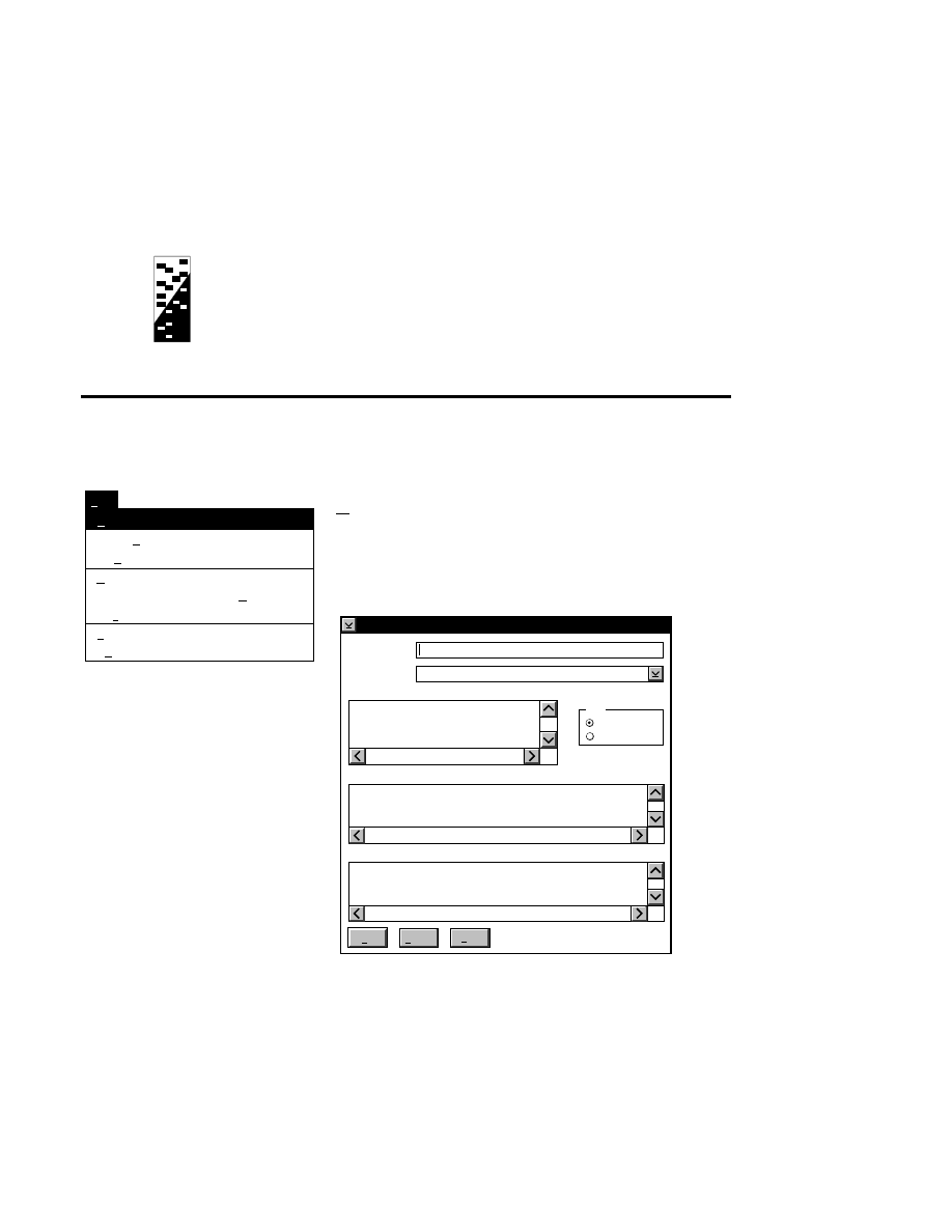
File Menu
2-1
22
2
2
Software
Commands
File Menu
Open Image...
Open Cropped Definition...
Open Sample File...
Save Cropped Definition
Save Cropped Definition As...
Save Image As...
Print...
Exit
File
Ctrl+O
Ctrl+C
Ctrl+E
Ctrl+S
Ctrl+A
Ctrl+V
Ctrl+P
F3
Open Image...
Ctrl + O
Opens an image file created in Data Collection (.IMG or .TIF
file extension), or an image file that was cropped and resaved
under a different file name (.IMG or .TIF extension). The
Open Image dialog box is displayed:
Open Image
Cancel
Help
OK
Image File:
..
[A:]
[B:]
[C:]
Date:
Sort
Name
Date
Image:
Remarks:
MMDDYY HHMMSS TESTIMG
Directories:
Format: IMG (LI-COR Base ImagIR Format)

Section 2
2-2
File Menu
There are two ways to open an existing image file:
1.
Type the path and name of the image file in the 'Image
File' field, and click
OK
.
2.
Select the desired image file in the list box, and click
OK
,
or double-click on the desired image file.
To change the path, double-click on the desired directory in
the Directories list box. Double-click on “••” in the
Directories list box to move one level higher in the Path
hierarchy. For example, if the path listed is C:\DNA4000,
double-clicking on “••” will change the path to the root
directory (C:\).
The image files in the list box can be sorted according to the
date the files were last modified, or alphabetically by name (in
ascending order). Click the appropriate radio button listed
under
Sort
to select the sorting method.
The Image Remarks text box displays any remarks entered
when the image file was created in Data Collection. These
remarks cannot be edited, but can be helpful in selecting the
desired image file.
Image Manipulation
File Menu
2-3
Open Image...
Open Cropped Definition...
Open Sample File...
Save Cropped Definition
Save Cropped Definition As...
Save Image As...
Print...
Exit
File
Ctrl+O
Ctrl+C
Ctrl+E
Ctrl+S
Ctrl+A
Ctrl+V
Ctrl+P
F3
Open Cropped Definition...
Ctrl + C
Brings up a dialog box in which you can open a crop definition
file. A crop definition file contains the settings for the image
size, image crop lines, intensity adjustments, and the tab
marker. It does not contain any image data and is similar in
nature to sample files in Image Analysis, in that an image can
have multiple crop files. The associated image file will be
opened when the crop definition file is opened. Crop
definition files are denoted by a .CRP file extension.
There are two ways to open an existing crop definition file:
1.
Type the path and name of the .CRP file in the 'Crop
Definition File' field, and click
Open
.
2.
Select the desired crop definition file in the list box, and
click
Open
, or double-click on the desired crop definition
file.
To change the path, double-click on the desired directory in
the Directories list box. Double-click on “••” in the
Directories list box to move one level higher in the Path
hierarchy. For example, if the path listed is C:\DNA4000,
double-clicking on “••” will change the path to the root
directory (C:\).
The image files in the list box can be sorted according to the
date the file was last modified, or alphabetically by crop file or
image file name (in ascending order). Choose the sorting
method by selecting the appropriate radio button listed under
Sort
.
The Cropping Information text box displays the cropping
parameters defined in the Crop Definition dialog box. These
Section 2
2-4
File Menu
parameters cannot be edited, but can be helpful in selecting the
desired crop definition file.
Open Image...
Open Cropped Definition...
Open Sample File...
Save Cropped Definition
Save Cropped Definition As...
Save Image As...
Print...
Exit
File
Ctrl+O
Ctrl+C
Ctrl+E
Ctrl+S
Ctrl+A
Ctrl+V
Ctrl+P
F3
Open Sample File...
Ctrl + E
Opens a sample file created in Image Analysis (.SMP file
extension), along with the associated image file. The Open
Sample File dialog box appears:
When a sample file is opened, the sequence text will be
displayed along the left edge of the window.
There are two ways to open an existing sample file:
1.
Type the path and name of the sample file in the 'Sample
File' field, and click
OK
.
2.
Select the desired sample file in the list box, and click
OK
,
or double-click on the desired file.
Open Image...
Open Cropped Definition...
Open Sample File...
Save Cropped Definition
Save Cropped Definition As...
Save Image As...
Print...
Exit
File
Ctrl+O
Ctrl+C
Ctrl+E
Ctrl+S
Ctrl+A
Ctrl+V
Ctrl+P
F3
Save Cropped Definition
Ctrl + S
Saves the crop definition parameters currently defined in the
Crop Definition dialog box to a file. This menu choice is
unavailable until the crop definition file has been named using
the Save Cropped Definition As menu choice (see below).
Save Cropped Definition As...
Ctrl + A
Opens the Save Cropped Image As dialog box, where you can
create a crop definition file, (using the cropping parameters
currently listed in the Crop Definition dialog box), or save the
current crop file under a different name. Crop definition files
can only be created with image files, not sample files.
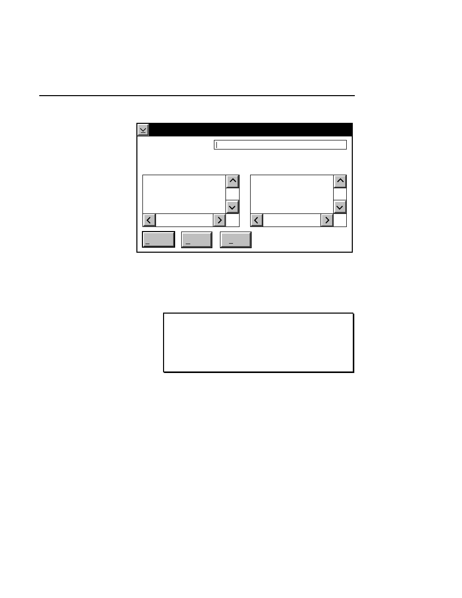
Image Manipulation
File Menu
2-5
Save Cropped Definition As
Cancel
Help
Save As
C:\DNA4200
..
[A:]
[B:]
[C:]
Directories:
Save as filename:
TEST.CRP
Files:
Enter the complete path and name of the new crop file in the
'Save as filename' field. If no path is specified, the file will be
saved to the directory shown. Existing crop definition files in
the directory listed are shown in the 'Files' list box.
Note that this function does not create a new image file.
When a crop definition file is opened later using the Open
Cropped Definition function, the original .tif image is
recalled to the screen. To create a new image file, use the
Save Image As function (below).
Section 2
2-6
File Menu
Open Image...
Open Cropped Definition...
Open Sample File...
Save Cropped Definition
Save Cropped Definition As...
Save Image As...
Print...
Exit
File
Ctrl+O
Ctrl+C
Ctrl+E
Ctrl+S
Ctrl+A
Ctrl+V
Ctrl+P
F3
Save Image As...
Ctrl + V
Exports the image file, as currently defined in the Crop
Definition, Image Size and Intensity Adjustment dialog boxes,
to a new file. Any of the following image file formats can be
selected for the new file:
File Type
File Extension
Alden 9315
ALD
Encapsulated Postscript
EPS
Graphics Interchange Format 89a
GIF
HP LaserJet (300 d.p.i.)
HPL
HP LaserJet (600 d.p.i.)
HPL
LI-COR Base ImagIR Format
IMG
PC Paintbrush
PCX
Tag Image Formation File, v. 5.0
TIF
File formats such as EPS, TIFF, GIF, and PCX are useful for
importing the image into electronic publishing software.
Other formats, such as HPL and ALD are printer output
formats. These file icons can be dragged and dropped onto
your printer icon for printing.
New image files created with this function can be opened
using the Open Image function; no other files are required to
view the new image.
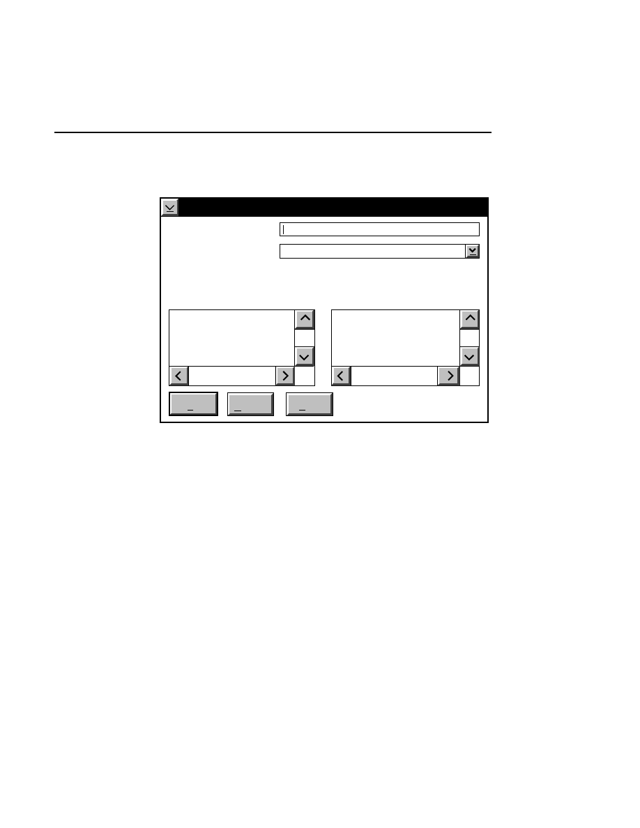
Image Manipulation
File Menu
2-7
Selecting Save Image As opens the Create File dialog box:
Create File
Cancel
Help
Create
Current Path: C:\DNA4200
..
[A:]
[B:]
[C:]
Directories:
Create filename:
Format to Use: TIF (Tag Image Formation File, v5.0)
TEST.TIF
Existing Files:
Enter the new filename in the 'Create Filename' text entry box.
It is not necessary to add a file extension; this will be added
automatically, based on the type of file selected in the 'Format
to Use' entry field.
Click on the arrow to the right of the 'Format to Use' field to
view and/or select the available file types. Click on a file type
to select it. The file will be saved to the directory listed at
'Current Path'. Change directories with the Directories list
box. Any existing files of the type shown in the 'Format to
Use' field will be shown in the ‘Existing Files’ list box.
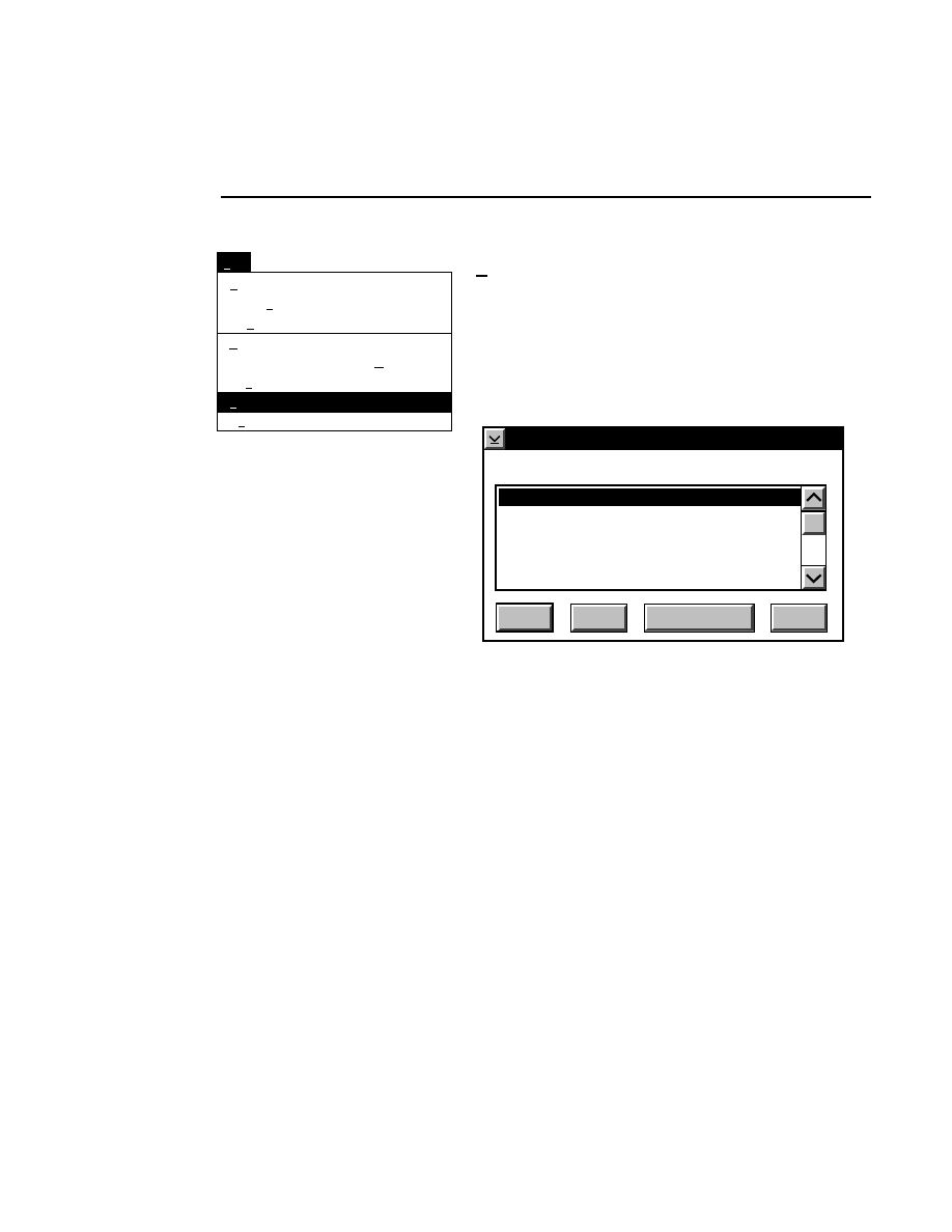
Section 2
2-8
File Menu
Open Image...
Open Cropped Definition...
Open Sample File...
Save Cropped Definition
Save Cropped Definition As...
Save Image As...
Print...
Exit
File
Ctrl+O
Ctrl+C
Ctrl+E
Ctrl+S
Ctrl+A
Ctrl+V
Ctrl+P
F3
Print...
Ctrl + P
Prints the image file, as currently defined in the Crop
Definition dialog, to the printer. The Printing Options dialog
box appears, in which you can select a printer to which to send
the file. The image files will be printed with all image
enhancements and size specifications. Sample files will be
printed with lane definitions and sequence text.
Printing Options
Cancel
Help
OK
Select printer
Job properties...
Alden 9315 CTP
Generic Post Script
HP Laser Jet (300 dpi)
HP Laser Jet (600 dpi)
Paint Jet
The printers listed in the Printing Options dialog box will vary
according to how your computer system is configured. When
Image Manipulation is started, the program will query the
operating system to find the printer icons installed on the
desktop. These printers will be listed in the Printing Options
dialog box. In addition, there are several printer drivers that
have been written by LI-COR specifically for use with the
Image Manipulation program.
The first five printers listed in the dialog are LI-COR printer
drivers; choosing any of these printers will cause the file to be
sent to the printer that is designated as the default printer on
the desktop. Note that because the non-LI-COR printer
drivers may not be optimized for image printing, the results
may not be as good as when using the LI-COR printer drivers.
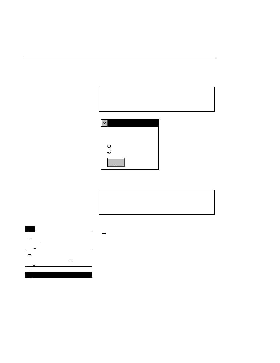
Image Manipulation
File Menu
2-9
Select the desired printer in the list box, and click
OK
.
NOTE: Only one image file can be printed at a time. If
you attempt to print another file before it has completed
the first job, the printer status dialog box appears (below).
Printer Status
OK
Print data is being
created.
Continue with printing
End print job
Select
End print job
and click
OK
to stop the current print job.
NOTE: You may need to turn the printer off and then on
again after canceling a print job in order to print the next
job properly.
Open Image...
Open Cropped Definition...
Open Sample File...
Save Cropped Definition
Save Cropped Definition As...
Save Image As...
Print...
Exit
File
Ctrl+O
Ctrl+C
Ctrl+E
Ctrl+S
Ctrl+A
Ctrl+V
Ctrl+P
F3
Exit
F3
Closes the Image Manipulation program.
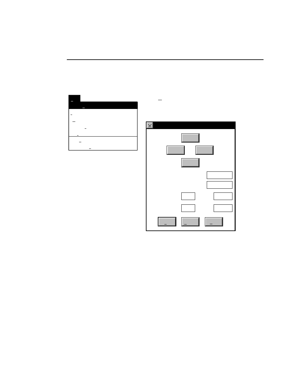
Section 2
2-10
Edit Menu
Edit Menu
Set Tab
Image Size...
Intensity Adjustment...
Clear Tab
Edit
Ctrl+M
Ctrl+I
Set Font...
Ctrl+N
Marker Color...
Ctrl+R
Ctrl+T
Ctrl+B
Crop Definition...
Ctrl+D
Crop Definition...
Ctrl + D
Opens the Cropping Definition dialog box, in which you can
define the cropping boundaries on the image file.
Cropping Definition
Cancel
Help
OK
Right Column Position:
Top Frame:
Line:
Bottom Frame:
Left Column Position:
Top
Right
Left
Bottom
Line:
0
767
511
0
1
25
The crop boundaries are defined in this dialog box by dragging
markers onto the image, or by entering the frame, line and
column numbers for the crop definition.
Click on the Top, Left, Right, or Bottom buttons to bring up
the respective crop cursors when the pointer is moved into the
Image window. Drag the cursor into position and click the
mouse button again to anchor it at that location. The value in

Image Manipulation
Edit Menu
2-11
the associated text box will change to reflect the position of
the cursor.
One frame of data in the image window is 512 lines high, as
shown below.
511
0
767
Image Window
Line
Column
0
The minimum and maximum values for the Left and Right
Column positions are 0 and 767, respectively. The Top Frame
value is determined by the total number of frames collected in
the original image file; the value cannot exceed the number of
frames collected. The maximum value for line numbers is
511. The minimum value for the Bottom Frame is frame 1,
line 0. If any of these values are entered incorrectly, an error
message will appear, asking that you re-enter one or more of
the parameters.
Example: You loaded 8 lanes (2 samples) onto the gel during
electrophoresis, collected 25 frames of data, and the bands
became indistinguishable after frame #18. You now want to

Section 2
2-12
Edit Menu
crop the image to save disk space. Here is how you might
crop the image using a combination of the crop markers and
the text entry boxes:
1.
In the Cropping Definition dialog box, click on the
Left
button. Move the cursor into the Image window. A
vertical cursor appears.
2.
Drag the cursor to the left edge of the area to be cropped,
and click the mouse button again to anchor the cursor.
Notice that the value in the 'Left Column Position' field
changes to reflect the position of the cursor.
3.
Repeat this process to set a cursor for the Right edge of
the crop area. If you make a mistake, simply click on the
Right
button again and reset the cursor.
4.
Enter '1' for the bottom frame number, line '0', and '18' for
the top frame number, line '511'. This will crop frames 1
through 18. Alternatively, you could scroll the image
with the scroll bar or the Page Up button, and set a crop
marker at the top of frame 18.
5.
Click
OK
. You have set the crop definition. You can
save this cropped file with a new name, or create a new
image file, if desired, using the
File
command on the Print
menu.
Image Manipulation
Edit Menu
2-13
Crop Definition...
Intensity Adjustment...
Image Size...
Set Font...
Marker Color...
Set Tab
Clear Tab
Edit
Ctrl+D
Ctrl+I
Ctrl+M
Ctrl+N
Ctrl+R
Ctrl+T
Ctrl+B
F3
Intensity Adjustment...
Ctrl + I
The Intensity Adjustment dialog box lets you change how the
image is displayed. When the 'Show' check box is enabled, the
changes are implemented in the Image window, allowing you
to adjust the image interactively using the Brightness,
Contrast, or Pseudo Color Adjust slider bars.
The Pseudo Color Adjust and the Brightness and Contrast
functions are enabled exclusively; in other words, if you are
using the Pseudo Color enhancement, the Brightness and
Contrast slider bars will not be usable.
Changes to the image brightness, contrast, and/or color
affect only the appearance of the image and not the
original image file. Changes are applied to new file
formats when using the Save Image As function.
Section 2
2-14
Edit Menu
Intensity Adjustment
Brightness 50
Show
Contrast 50
Cancel
OK
Help
Default
Reset
✔
Image Style
Pseudo Color
White on Black
Black on White
Pseudo Color Adjust
Green:
Blue:
Red:
Sensitivity [xx]
Pseudo Color Adjust
When the image file was created in Data Collection, each pixel
of the image was assigned an intensity value based on the
fluorescence detected by the laser/microscope assembly as it
Image Manipulation
Edit Menu
2-15
scanned across the gel. Areas of the gel where low
fluorescence was detected became background pixels, while
areas of the gel with high fluorescence became bands.
When the image style is set to
Pseudo Color
, the pixels on the
image are remapped with a combination of red, blue, and
green. The amount of each color is determined by the position
of the respective slider bar, with 0% at the far left, and 100%
at the far right. When Pseudo Color is enabled, the default
slider bar positions appear as shown below.
Pseudo Color Adjust
Green:
Blue:
Red:
Picture three adjacent hyperbolic curves, as shown below.
These curves represent the color intensity of the remapped
pixels at the default slider bar positions. As you can see, those
pixels with the highest raw signal strength (the bands) are
remapped with a high percentage of red. Pixels with the
lowest raw signal strength (the background) receive a high
percentage of blue, and those with medium strength receive a
high percentage of green.
Section 2
2-16
Edit Menu
Raw data signal strength
Color intensity
Red
Blue
Green
0
255
255
If you move the slider bars right or left to increase or decrease
the amount of color, the hyperbolic curves in our repre-
sentation also move right or left. For example, if you move
the Blue slider bar to the right, so that it appears as shown
below, the bands will now be mapped with a mix of red and
blue, so that they appear purple. The background pixels still
have a much weaker signal strength than the bands, so they
appear green.
Pseudo Color Adjust
Green:
Blue:
Red:
Raw data signal strength
Color intensity
Red
Blue
Green
0
255
255

Image Manipulation
Edit Menu
2-17
Experiment with the Pseudo Color enhancement yourself -
personal preference will dictate how you want the image to
appear.
Brightness and Contrast Adjustments
The
Sensitivity
slider bar changes the lookup table that is
applied to the image when data are collected in 16-bit mode.
Values from 0 to 7 can be applied to the data; experiment by
moving the slider bar until the image appears as desired. This
slider bar will be greyed out when data are collected in 8-bit
mode.
The
Brightness
slider bar changes the value of the average
background intensity. Moving the slider to the left (or clicking
the left arrow button) reduces the background value. As the
brightness value displayed above the slider bar approaches
zero, the average background gets darker (when viewing white
bands on a black background). Moving the slider to the right
increases the average background intensity, making the image
background appear lighter as the brightness value approaches
100.
The
Contrast
slider bar changes the average background
noise. Moving the slider to the left (or clicking the left arrow
button) reduces the background noise of the image. As the
contrast number displayed above the slider bar approaches
zero, the background of the image will appear less grainy and
more uniform. This also results in the bands being less
distinct. Moving the slider to the right increases the
background noise of the image, making the background more
grainy and the bands somewhat easier to distinguish.
When the
Show
check box is checked, the image is redrawn
each time you move the slider bars. Disable the Show check

Section 2
2-18
Edit Menu
box to make multiple adjustments to the slider bar positions
without redrawing the image. Enable the check box again to
view the changes.
In the
Intensity Adjustment
dialog box:
Press
to...
Default
Reset the image display to the default
brightness, contrast, and/or Pseudo
Color settings.
Reset
Change the image back to the form it
was in when the dialog box was opened.
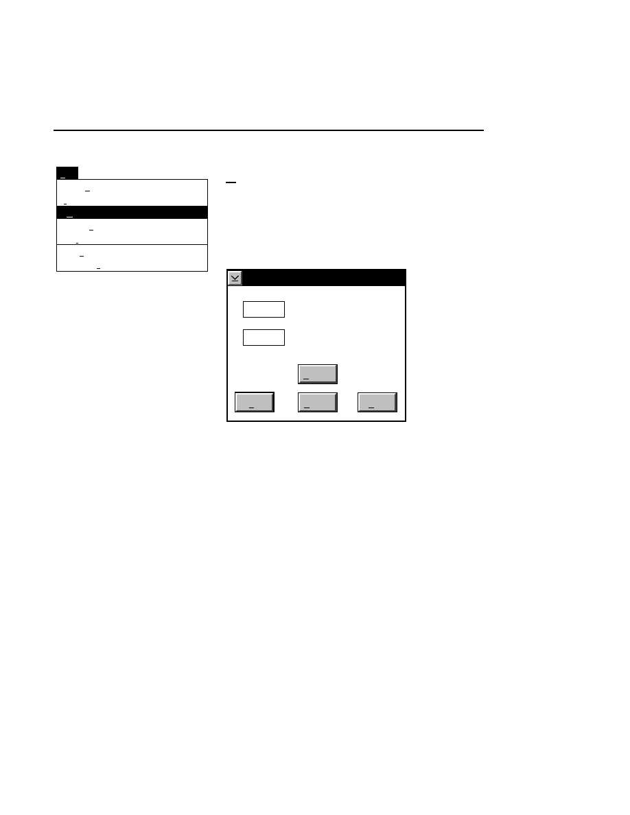
Image Manipulation
Edit Menu
2-19
Crop Definition...
Intensity Adjustment...
Image Size...
Set Font...
Marker Color...
Set Tab
Clear Tab
Edit
Ctrl+D
Ctrl+I
Ctrl+M
Ctrl+N
Ctrl+R
Ctrl+T
Ctrl+B
F3
Image Size...
Ctrl + M
The Image Size dialog box lets you change the size of the
image displayed in the Image window. The image can be
enlarged or reduced, either proportionately or non-proportion-
ately. This resized image can then be printed to an alternate
file format or to the printer.
Image Size
Cancel
Help
OK
Horizontal Multiplier (%)
Default
100
100
Vertical Multiplier (%)
The image can be resized in either of two ways; with the
dialog box or with the mouse.

Section 2
2-20
Edit Menu
Using the Image Size Dialog Box
To specify the scale, type the appropriate percentages into the
Horizontal and Vertical multiplier fields. The multiplier range
is 10 to 1000.
Using the Mouse
The image can be scaled at any time without using the Image
Size dialog box by dragging the image window border(s)
while holding down the right mouse button. If you double the
size of the window (both horizontally and vertically), and then
open the Image size dialog, you will find that the Horizontal
and Vertical multiplier fields read about 200%. Similarly, if
you halve the size of the window, the multiplier fields will
read about 50%.
The scaling process can be performed several times in
succession, also, so that the effects are additive. For example,
let's say that you want to scale the image to about 200% of the
original size in the horizontal dimension only. Follow these
steps:
●
Drag the right border of the window to the right, while
holding the right mouse button, until you reach the edge
of the screen.
●
Now drag the same border to the left while holding the
left mouse button, so that the window size is reduced to
about half of the current size. Sizing the window with the
left mouse button affects only the window size, not the
image size.
●
Enlarge the window while holding the right mouse button
again. If you open the Image Size dialog box, you will
notice that only the horizontal multiplier has changed.
This process can be repeated multiple times, within the
defined size limits, to enlarge or reduce the image.
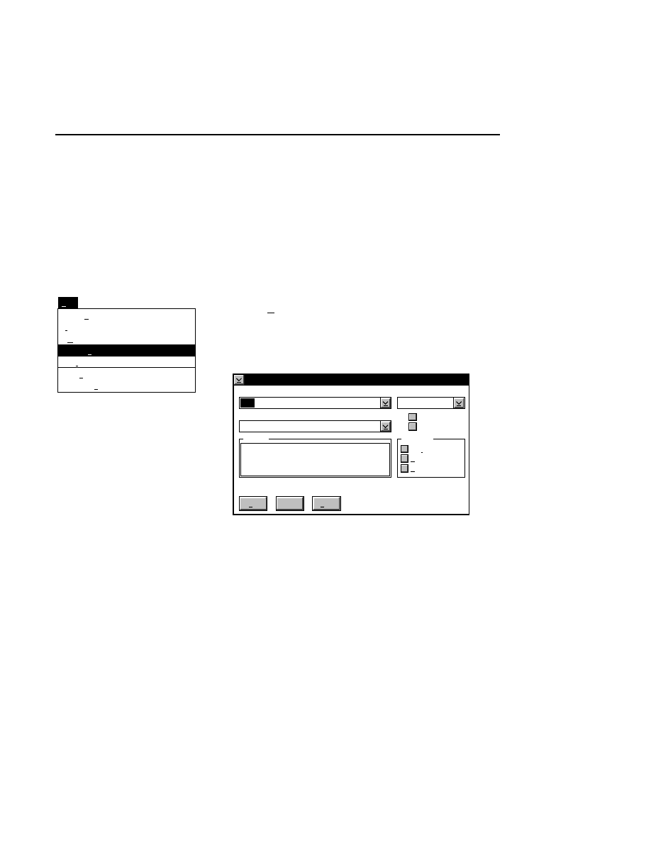
Image Manipulation
Edit Menu
2-21
The image window can be enlarged to fill the screen by
clicking on the maximize button in the upper righthand corner
of the window, or by double-clicking anywhere on the
window's title bar. Clicking the maximize button or double-
clicking on the title bar will return the window to its previous
size. Both of these shortcuts scale the image accordingly.
Press
Default
to reset the multiplier values to 100%.
Crop Definition...
Intensity Adjustment...
Image Size...
Set Font...
Marker Color...
Set Tab
Clear Tab
Edit
Ctrl+D
Ctrl+I
Ctrl+M
Ctrl+N
Ctrl+R
Ctrl+T
Ctrl+B
F3
Set Font...
Ctrl + N
Opens the Font dialog box, where you can change the font size
and/or font style used to display and print the sequence text,
when a sample file is open.
Font
Cancel
Help
Ok
Name
Helv
Normal
Size
10
Display
Outline
Underline
Strikeout
abcdABCD
Sample
Style
Printer
Emphasis
✔
Select the font type in the 'Name' field; the available sizes for
that font will be shown under the 'Size' field.
Changing the font size can be useful for viewing and printing
sample files that have been reduced in size, or in cases where
the bands are very close together, where large font sizes may
cause the sequence text to overlap.
System fonts may not print correctly, as they are screen fonts
intended for display only.
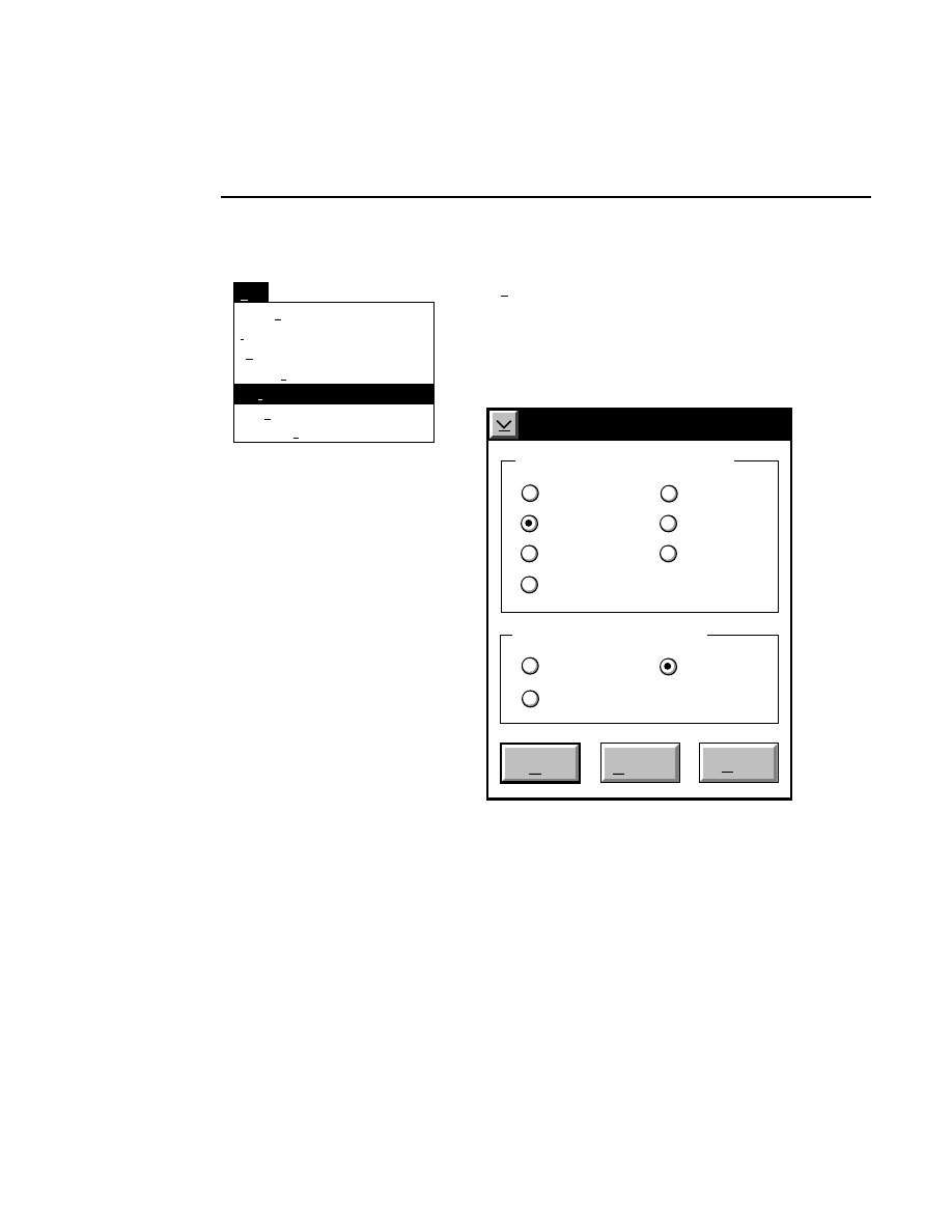
Section 2
2-22
Edit Menu
Set Tab
Image Size...
Intensity Adjustment...
Clear Tab
Edit
Ctrl+M
Ctrl+I
Set Font...
Ctrl+N
Ctrl+T
Ctrl+B
Crop Definition...
Ctrl+D
Marker Color...
Ctrl+R
Marker Color...
Ctrl + R
Opens the Band Style dialog box, where you can change the
color of the band markers for display and/or printing, when a
sample file is open. You can also turn the band markers off, if
desired.
Band Style
Black
Do Not Print
Cancel
OK
Help
Band Style for Displaying
Red
Green
Black
Do Not Display
Blue
Pink
White
White
Band Style for Printing
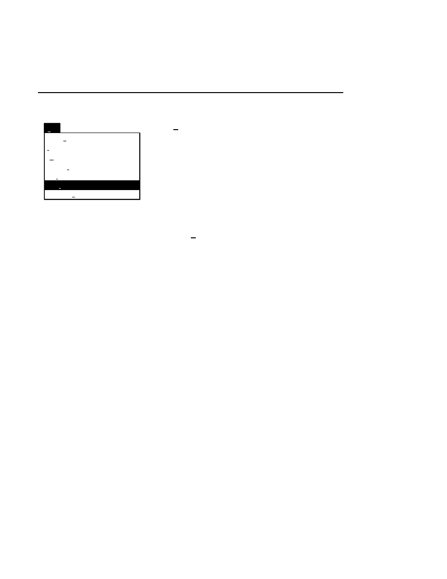
Image Manipulation
Edit Menu
2-23
Image Size...
Intensity Adjustment...
Clear Tab
Edit
Ctrl+M
Ctrl+I
Set Font...
Ctrl+N
Marker Color...
Ctrl+R
Ctrl+B
Crop Definition...
Ctrl+D
Set Tab
Ctrl+T
Set Tab
Ctrl + T
The tab marker serves as a reference point for the Goto Tab
function, which can be used to scroll the image very quickly.
Prior to setting the tab, scroll the image to the frame which you
want to contain the tab marker. When Set tab is selected, a
horizontal line appears across the image. Use the mouse to
move the tab marker to the desired location, and click the
mouse button once to set the tab at that location.
Clear Tab
Ctrl + B
Removes the tab marker from the Image window.
Section 2
2-24
Goto Menu
Goto Menu
Tab
Goto
Tab
Frame...
Ctrl+F
Frame...
Ctrl + F
Scrolls the image to the frame number specified in the Goto
Frame dialog box. A frame consists of 512 rows of image
data.
Goto Frame
Go To Frame:
Cancel
OK
Help
1
Current Frame: 4
Type the frame number to which the image will be scrolled.
Click
OK
to scroll the image, or
Cancel
to close the dialog
box without scrolling the image.
Goto
Frame...
Ctrl+F
Tab
Tab
Tab
Tab
Scrolls the image to the tab set with the Set Tab function on
the Edit menu. If a tab has not been set in the Image
Manipulation program, the image will scroll to the tab location
set during Data Collection, if present. If no tab is set, this
menu selection cannot be chosen.
Image Manipulation
Windows Menu
2-25
Windows Menu
The Windows menu allows you to open Log, Image, and
Sample Notepads for the associated image and/or sample files.
The notepads are for review only; there are no editing
capabilities.
Image Notepad...
Sample Notepad...
Windows
Ctrl+G
Ctrl+L
Log Notepad...
Ctrl+U
Log Notepad
Ctrl + U
Opens the Log Notepad created with the image file during
Data Collection.
Sample Notepad
Ctrl + L
Opens the Sample Notepad created with the sample file during
Image Analysis. This notepad is available only when a sample
file is opened in Image Manipulation.
Image Notepad
Ctrl + G
Opens the Image Notepad created with the image file during
Data Collection.
Section 2
2-26
Options Menu
Options Menu
Capture to File...
Options
F12
Capture to Printer...
F11
Capture to Printer...
F11
Prints the portion of the image file currently displayed in the
window to the system printer. This option is similar to the
Print function on the File menu, with the exception that only
the portion of the image currently displayed is printed, and is
independent of the crop definition. The Printing Options
dialog box appears:
Printing Options
Cancel
Help
OK
Select printer
Job properties...
Alden 9315 CTP
Generic Post Script
HP Laser Jet (300 dpi)
HP Laser Jet (600 dpi)
Paint Jet
Select the desired printer in the list box, and click
OK
.

Image Manipulation
Options Menu
2-27
Options
Capture to Printer... F11
Capture to File...
F12
Capture to File...
F12
Prints the portion of the image file currently displayed in the
window to a new file.
Selecting Capture to File opens the Create File dialog box.
Enter the new filename in the 'Create Filename' text entry box.
It is not necessary to add a file extension; it will be added
automatically, based on the type of file selected in the 'Format
to Use' entry field.
Click on the arrow to the right of the 'Format to Use' field to
view and/or select the available file types. Click on a file type
to select it. The file will be saved to the directory listed at
'Current Path'. Change directories with the Directories list
box. Existing files of the type shown in the 'Format to Use'
field will be shown in the ‘Existing Files’ list box.
Any of the following formats can be selected for the new file:
File Type
File Extension
Alden 9315
ALD
Encapsulated Postscript
EPS
Graphics Interchange Format 89a
GIF
HP LaserJet (300 d.p.i.)
HPL
HP LaserJet (600 d.p.i.)
HPL
LI-COR Base ImagIR Format
IMG
PC Paintbrush
PCX
Tag Image Formation File, v. 5.0
TIF
File formats such as EPS, TIFF, GIF, and PCX are useful for
importing the image into electronic publishing software. Other
formats, such as HPL and ALD, are printer output formats.

Error Messages
3-1
3
Error
Messages
You may occasionally encounter error messages while using
the Image Manipulation software. Press the
Help
button (if
available) or the
F1
key when an error message is displayed to
see a help panel listing these messages. Double-click on the
message in the list to see a description and possible solutions
to the problem. Some of the common error messages are
described below. Others are possible, but they may require
more complex solutions.
Cannot Go There, First Frame Is...
The number entered in the Goto Frame dialog box is less than
or equal to zero. The first frame of the image is designated as
frame #1.
Cannot Go There, Total Frames Are...
The number entered in the Goto Frame dialog box exceeds the
total number of frames in the image. When you click
OK
the
image will be scrolled to the last available frame.

Section 3
3-2
Error Messages
Compression Ratio Exceeds Limit
When sizing the image with the mouse, you cannot exceed the
limits of compression for the image, which are 10% of the
original size in both horizontal and vertical dimensions.
Crop Definition Error
The value for the 'Left' column position must be greater than
or equal to zero, and must be less than the value for the 'Right'
column position. Similarly, the value for the 'Right' column
position cannot exceed the width of the image file. The
bottom of the crop definition must also be below the top.
Disk Error
The disk in the specified drive may not be formatted. Try
another disk, or use the FORMAT command in the OS/2
window to format the disk.
Disk Full
The disk does not contain enough free space for the file that is
being written. Use another disk/drive.
The CHKDSK command at the OS/2 prompt and/or the Disk
Information program can be used to determine the status of the
disk.

Image Manipulation
Error Messages
3-3
File Already Exists
The Overwrite error message is displayed because the file
name you have typed already exists. If you want to overwrite
the file click the YES button.
NOTE: You cannot overwrite original LI-COR image
files (.IMG file extension) or image files that have been
converted to other file types. You can, however, over-
write crop definition files.
File Not Found
The file name entered does not exist in the directory of the
specified drive. Enter the file name again using the correct
name.
File Open Failed
The file that you have tried to open does not exist. Check the
path and the spelling of the file name to make sure they are
correct.
Input Image is Unknown
The file that you are trying to open is not recognized as a
LI-COR image file or a gray scale TIFF file. Image files must
be created from within the Base ImagIR Data Collection
program, or by saving an original image file under a different
name in Image Manipulation.

Section 3
3-4
Error Messages
Multiplier is Too Large
The value entered for one or both of the multiplier values in
the Image Size dialog is too large. The maximum value for
the multipliers is 1000%.
Multiplier is Too Small
The value entered for one or both of the multiplier values in
the Image Size dialog is too small. The minimum value for
the multipliers is 10%.
Not a Crop File
The file that you are trying to open is not recognized as a crop
definition file. Crop definition files must be created from
within the Image Manipulation program.
Path Not Found
The file or path name entered does not exist in the directory of
the specified drive. Enter the file name and/or path again
using the correct name.
Printer Port Error
The printer selected is not properly connected, or the printer
configuration set for that printer is incorrect. Make sure that
the printer is turned on and connected properly, and that the
proper serial or parallel printer port is selected for that printer.
Quick SequencIR V3.0
1-1
Quick
SequencIR
Table of Contents
page

Section 1
1-2
Quick SequencIR V3.0
Overview
Quick SequencIR is a program that is designed to completely
automate the process of Data Collection and Image Analysis.
When Quick SequencIR is run, Data Collection will be
opened, and will begin collecting image data based on the
electrophoresis parameters set in the active configuration file.
Image Analysis will then be opened, which will automatically
find the lanes and begin sequencing the samples, again based
on the sample definitions found in the active Image Analysis
configuration file.
An example of how to use Quick SequencIR follows; detailed
descriptions of individual Quick SequencIR windows can be
found later in this section.
Note, too, that helpful hints are available at the bottom of the
Quick SequencIR notebook; the hints change as you move the
cursor over different areas of the window.
Example
You want to use Quick SequencIR to collect image data on
both channels. Samples are loaded using a 48-well square-
tooth comb. Follow these steps to collect your image data:
1.
Double-click on the Quick SequencIR icon to open the
program. The Project window is shown.
2.
Edit the Project Name, if desired. A directory of this
name will be created within the Project Location shown.
All files will be saved to this directory.

Quick SequencIR
Quick SequencIR V3.0
1-3
3.
Click on the Electrophoresis tab. The Electrophoresis
window appears.
4.
Select the Data Collection configuration file that will be
used to control the electrophoresis parameters. Note that
this configuration file must be a Quick SequencIR
configuration file; they are denoted by a Q as the first
letter.
This file will serve as a template, or starting point, from
which you can edit the parameters as desired. A new
collection configuration file with the Project name you
entered in step #2 will automatically be created, so you
don't have to worry about making changes to the original
file.
If you don't see the configuration file that you want in the
list box, press the
Find
button to search for the file.
5.
If you need to make changes, or simply view the
configuration file, press the
Edit
button to open the
Collection Configuration program. After you are done
viewing and/or editing the file, press
OK
.
6.
Click on the Comb notebook tab. This page allows you to
search for and/or select a configuration template for
Analysis. Click on the arrow to the right of the
configuration file name and select the Square48.anl file.
7.
Click on the Adv. Options notebook tab. There is a page
here that contains general setup parameters for Quick
SequencIR, including whether or not you want to
minimize the programs after they open, and when to stop
sequencing. Normally no action is required on the
Options page. Edit, if needed, and press
Start run
.
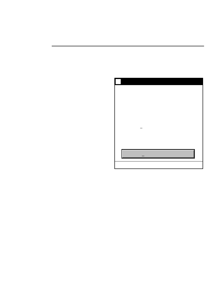
Section 1
1-4
Quick SequencIR V3.0
8.
The Data Collection program will open, and will perform
focus and autogain routines for both channels. The
following dialog will appear:
Quick4200 v4.00
Verify Loading
Wait for the Prerun to complete
then:
* Open Door
* Load Samples
* Press the Verify Loading button
Time remaining for Auto Focus &
Gain: 4:46
Wait for prerun and loading to be complete
After the prerun is completed, load your samples and
press Verify Loading. You will now have an opportunity
to enter the loading order into the analysis configuration
files.
After you have entered the loading order, the following
message will appear:
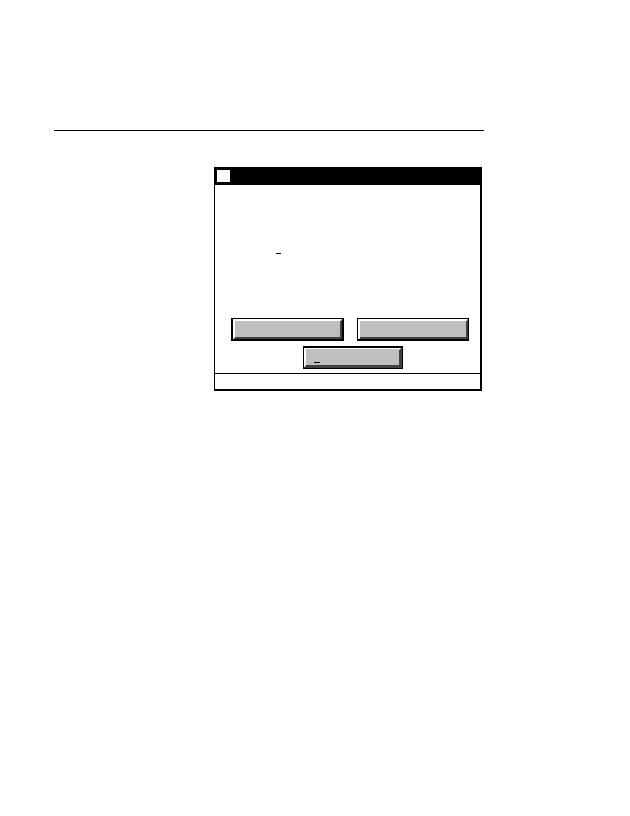
Quick SequencIR
Quick SequencIR V3.0
1-5
Quick4200 v4.00
Reverify Channel 800
Start Sequencing
Reverify Channel 700
* Close Door
* Press Enter on the Scanner
Press the Start Sequencing button
to start sequencing all active
channels. Press the Reverify button
to reverify comb and lane loading
for that channel.
Sequence data
Press the
Reverify Channel
button(s) to edit the analysis
configuration files, if necessary. This will be your last
opportunity to do so. When you are finished, press
Start
Sequencing
. The Image Analysis programs will open,
and Data Collection will begin collecting image data.
If you want to quit Quick SequencIR at any time during the
electrophoresis run, simply close the Data Collection and
Image Analysis programs by double-clicking on the system
menu icon in each program.
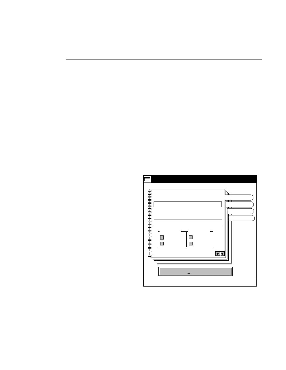
Section 1
1-6
Quick SequencIR V3.0
Project Window
The Quick SequencIR Project window has editable fields for
entering the project location and name. The default project
name is MMDDYYSN, where N is the GPIB device number,
and the month, day, and year are derived from the system
clock. Edit the project name, if desired. When you press
Start
run
, the resulting image files and all other associated files (i.e.,
sample, notepads, etc.) will be saved in a folder of this name,
located in the project path directory.
For example, if the project location is C:\DNA4200\Data (the
default), and the project name is TEST, a folder named TEST
would be created in the DNA4200 directory, and would
contain the resulting image and other associated files.
Start run
Quick 4200 v4.00
Project Location
Project Name
C:\DNA4200\DATA
Quick4200 setup notebook
021497S7
Electrophoresis
Comb
Adv Options
Project
Channel 800
Collect
Sequence
Channel 700
Collect
Sequence
✔
✔
✔
✔
Quick SequencIR Project window.

Quick SequencIR
Quick SequencIR V3.0
1-7
Clicking on the notebook tabs opens other windows that allow
you to change the working parameters of the Quick SequencIR
program. These parameters include the location of the
configuration file(s) to be used with the Data Collection and
Image Analysis programs.
Check the Collect and Sequence check boxes for the
channel(s) for which you want to collect image data, and
subsequently have Image Analysis sequence.
Electrophoresis Window
The Electrophoresis window contains a field where you can
enter the Collection program configuration file that will be
active when Data Collection starts up. If a configuration file is
not specified, the DEFAULT.COL file will be used.
Note that the configuration file specified serves only as a
template; a new configuration file with the same name as the
project specified on the Project page will be created each time
Quick SequencIR is run. In some instances you may want to
edit the existing configuration file, or view it to make sure that
the electrophoresis parameters for your run are correct.
Press
Find
to open a dialog containing File and Directory list
boxes, where you can search for the desired configuration file.
Press
Edit
to open the specified configuration file for review
and/or editing.
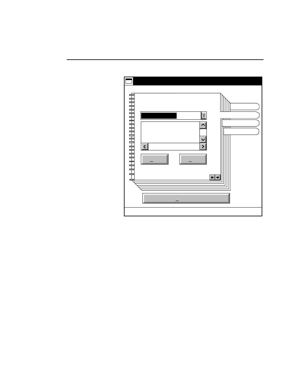
Section 1
1-8
Quick SequencIR V3.0
Start run
Quick4200 v4.00
C:\DNA4200
Default QuickseqIR
parameters for 4200
(41cm gel)
Electrophoresis
Quick4200 setup notebook
Find
Edit
QDEFAULT.COL
16 bit Data
Electrophoresis
Comb
Adv Options
Project
Electrophoresis Window.
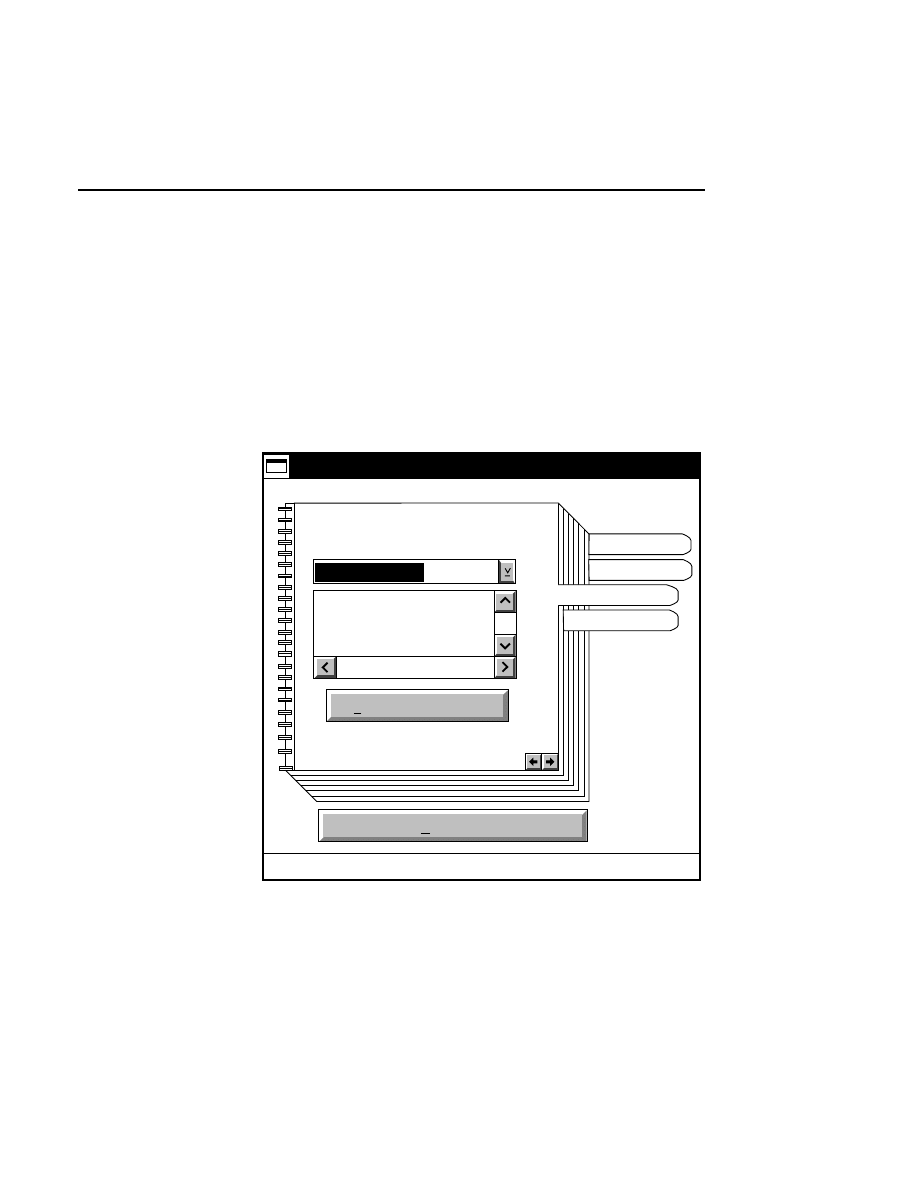
Quick SequencIR
Quick SequencIR V3.0
1-9
Comb Window
The Comb window contains an area where you can select the
template for the Image Analysis configuration file that will be
used to sequence the image.
Press
Find new config file
to open a dialog containing File
and Directory list boxes, where you can search for the desired
configuration file.
Start run
Quick4200 v4.00
C:\DNA4200
This file does not
contain a remark.
Comb
Quick4200 setup notebook
Find new config file
DEFAULT.ANL
Electrophoresis
Comb
Adv Options
Project
Comb Window.
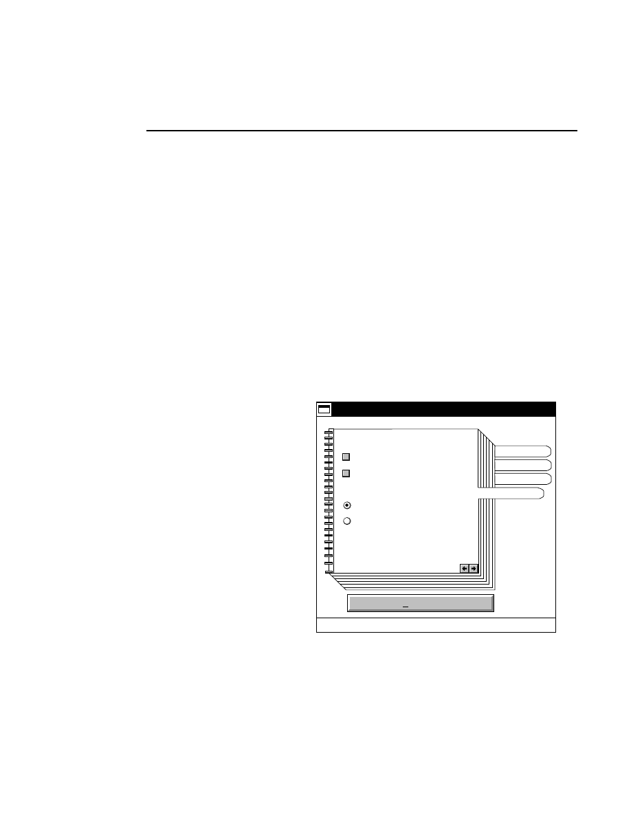
Section 1
1-10
Quick SequencIR V3.0
Advanced Options Window
You can choose whether or not to collect image data on either
channel in the Setup window, and if you want Image Analysis
to sequence the image data collected, by selecting the
appropriate check boxes.
Enable the 'Run Collection Minimized' check box to minimize
the Data Collection program after it starts up.
Enable the 'Run Analysis Minimized' check box to minimize
the Image Analysis program after it starts up.
The Advanced Options window also contains check boxes that
allow sequencing to the end of each sample file, or until the
software determines that the required level of confidence in
calling bases can not be maintained (Auto Stop).
Start run
Quick4200 v4.00
Advanced Parameters
Stop Sequencing
Auto Stop
End of data
Quick4200 setup notebook
Electrophoresis
Comb
Adv Options
Project
Run Collection Minimized
✔
Run Analysis Minimized
✔
Advanced Options Window.

SCF File Creation
2-1
SCF File
Creation
Table of Contents
page

Section 2
2-2
SCF File Creation
Overview
The .SCF File Creation Program will convert LI-COR sample
files into a standardized format (.SCF) developed by Roger
Staden and Simon Dear at the Sanger Centre in Cambridge,
England. This chromatogram format includes the curve data
for all four base types.
Instructions for converting sample files are given below,
followed by some important operational notes. Please read
these notes before performing file conversions.
Conversion
There are three methods for converting LI-COR sample files
(.SMP file extension) into .SCF files; by dragging and
dropping sample file icons onto the SCF program icon, by
double-clicking on the .SCF File Creation program icon to
open the creation window, or via the OS/2 command line
editor.
1. Dragging & Dropping
Double-click on the Drives folder icon, and double-click again
on the drive where the sample files are located. A directory of
the folders in the selected drive will appear. Locate and open
the folder containing the sample file(s) to be converted. Drag
the sample file icon onto the SCF File Creation program icon.
The SCF Creation window will open and the file(s) will be
converted.
To convert multiple sample files, select all of the sample file
icons by dragging a box around the icons, or by holding down
the
Ctrl
key while clicking the mouse button on the icons.
Drag the icons onto the SCF File Creation program icon. The
sample files will be converted consecutively.

SCF File Creation
SCF File Creation
2-3
2. Double-clicking the Program Icon
Double-click on the SCF File Creation Program icon to open
the SCF File Creation window. You will be prompted to enter
the sample file names that you want to convert. Enter the
complete path (if different than C:\DNA4200) and sample file
name, and press
Enter
. The file will be converted, and placed
in the same directory as the original sample file.
It is not necessary to add the .SMP file extension when
specifying the path. For converting multiple sample files,
wildcard characters can also be used. For example, to convert
sample files named TEST01, TEST02,...TEST12, you could
enter MKSCF TEST*; the resulting files would be named
TEST01.SCF, TEST02.SCF, etc.
3. Command Line
At an OS/2 system prompt (i.e., from an OS/2 Window),
change the drive and directory to the location of the sample
files to be converted. If the MKSCF.EXE file is not located in
this directory, you must enter the path to the MKSCF file,
also. At the prompt enter
<Path> MKSCF <Samplefile> <Enter>
The SCF Conversion window will open, and after conversion,
the .SCF file will be given the same name as the original
sample file (with a .SCF file extension), and will be placed in
the same directory as the sample file.
It is not necessary to add the .SMP file extension when
specifying the path. For converting multiple sample files,
wildcard characters can also be used. For example, to convert
sample files named TEST01, TEST02,...TEST12, you could
enter MKSCF TEST*; the resulting files would be named
TEST01.SCF, TEST02.SCF, etc.
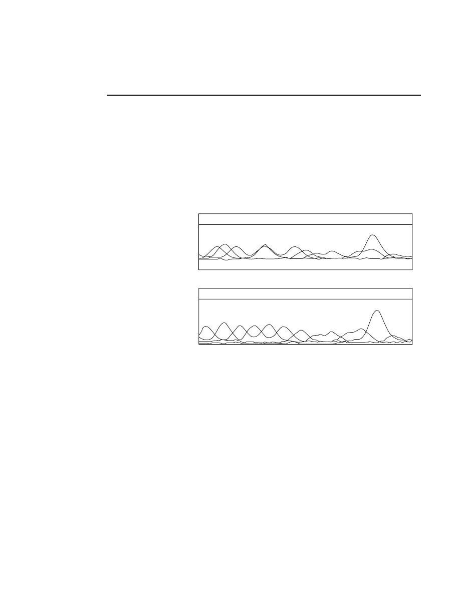
Section 2
2-4
SCF File Creation
Important Program Notes
The SCF File Conversion Program can generate files based on
image data that is corrected for differences in lane mobility, as
well as from the raw image data. We recommend that you use
the shifted data to generate the .SCF file (this is the default), as
it may be difficult to interpret the sequence text reliably using
the raw data, as shown below.
A
A
A
A
A
G
C
C
T
G
G
C
G
G
A
A
A
A
A
G
#390
#400
C
C
T
G
G
C
G
G
A
A
A
A
A G
C
C
T G
G
C
G
G
A
A
A
A
A G
#390
#400
C
C
T
G
G
C
G
G
Raw Data
Corrected Data
In the graphic representations above, the top illustration shows
a portion of an SCF file generated from raw image data that is
not corrected for lane mobility differences. Due to differences
in lane mobility, at base #392 the A and C curves nearly
overlap, making it difficult to discern the correct base call.

SCF File Creation
SCF File Creation
2-5
In the bottom illustration, “shift” was used while
autosequencing the sample, to correct for differences in
mobility between the lanes. Note too that in the corrected
data, the curves’ vertical offset has been removed, and the
curves were rescaled. When viewing the raw data, the
apparent sequence indicated by the curves may not match the
original sequence text.
Additional program notes:
●
Viewing raw image data - to view image data that has not
been corrected for differences in lane mobility, you can
enter MKSCF /R at the command line. You can also enter
/R in the Parameters field of the Settings Notebook to drag
and drop sample file icons onto the SCF Program icon and
output the files using raw image data.
Note that the .SCF file will be given the same name as the
original sample file, regardless of whether the output file is
generated as raw or shifted data. Therefore, if you want to
compare shifted and unshifted .SCF files, you must first
convert the file, rename it, and then convert it again.
●
There must be approximately 1/3 of a page of image data
beyond the last base called in the sample file. If the image
is cropped too close to the last base called, the conversion
program will abort with an unusable .SCF file generated.
●
The curve generation algorithm uses information derived
from the autosequencing lane definitions present in the
sample files. Samples that have been sequenced manually
may produce unexpected results when converted to .SCF
format, because the lanes may be tracked differently than a
human operator would have tracked them.
●
If the path to the image file (stored in the sample file) is no
longer valid, (i.e., the image file has been moved), the
program will look in the current directory for the image
file. If the image file is not found, the program will ask
you to enter the new path and name of the image file.

SCF ViewIR
3-1
SCF ViewIR
Table of Contents
page
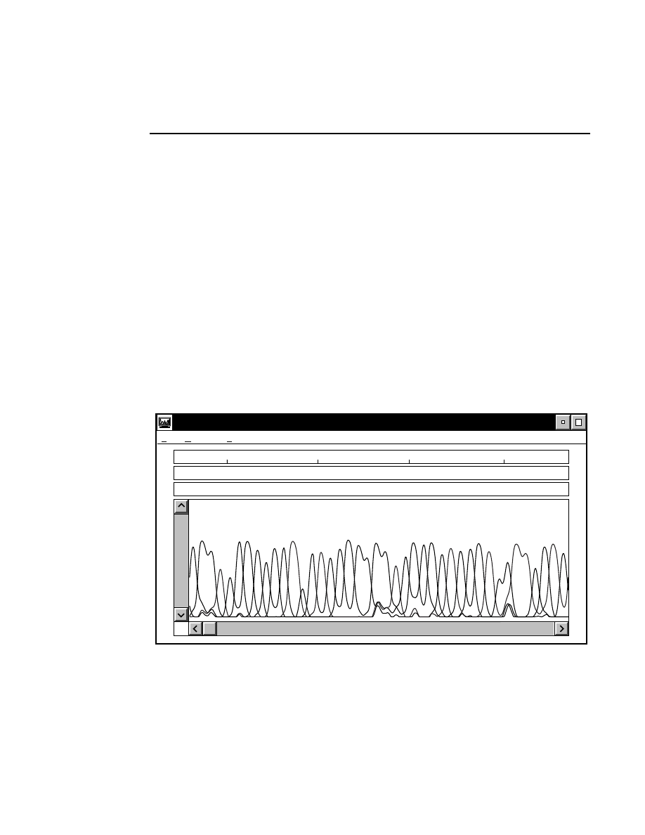
Section 3
3-2
SCF ViewIR
Introduction
SCF ViewIR is a program that allows you to view, print and
edit .SCF files created from LI-COR sample files with Image
Analysis or the SCF File Creation program.
When an SCF file is opened, the chromatogram will appear in
the Primary window, beneath three text fields (below). The
uppermost text field contains the base numbers (at 10-base
intervals). The lower two text fields contain the original base
calls from the associated sample file, and an identical set of
base calls that can be edited.
The chromatogram can be enlarged or reduced, and markers
showing the actual data points from the associated image file
can be placed on the curves.
520
530
540
550
C:\DNA4000\TEST01.SCF <801 Bases>
File Options Help
G
G
G
G
G
G
G
G
G
C
C
C
C
C
C
A
A
A
A
A
A A
A
A
A
A
A
T T
T
T
T
T
T
T
T
T
T
T
T
T
G
G
G
G
G
G
G
G
G
C
C
C
C
C
C
A
A
A
A
A
A A
A
A
A
A
A
T T
T
T
T
T
T
T
T
T
T
T
T
T
SCF ViewIR primary window.
SCF ViewIR
SCF ViewIR - File Menu
3-3
File Menu
Printer...
Print... Ctrl+P
Save as...
Save
Print setup...
File
Close F3
Open...
Open...
Select
Open
to open an SCF file created with the SCF File
Creation program. The Open dialog box will be displayed:
Open
Cancel
Help
Open
Open filename:
Drive:
File:
Directory:
Type of file:
<All Files>
C: [OS2]
C: \
DNA4200
SCF
*.SCF
There are several ways to open SCF files with the Open
dialog:
1.
If the displayed drive and directory is correct, type the
name of the SCF file in the ‘Open Filename’ field, and
click the
Open
button.
2.
Type the complete path and name of the SCF file in the
‘Open Filename’ field, and click
Open
.
3.
Use the Drive and Directory list boxes to select the
appropriate path, and double-click on the desired SCF file
in the File list box.
Section 3
3-4
SCF ViewIR - File Menu
When the SCF file is opened, the chromatogram will be
displayed along with the base calls and base numbers.
Printer...
Print... Ctrl+P
Save as...
Print setup...
File
Close F3
Open...
Save
Save
Saves the current SCF file to disk.
Save as...
Opens the Save As dialog box, where you can save the current
SCF file to a file with a different name.
Enter the new name in the 'Save as filename' field. You do not
need to add the .SCF file extension; it will be appended
automatically. The file will be saved to the directory shown in
the 'Directory' list box. Use the Drive and/or Directory list
boxes to change the path.
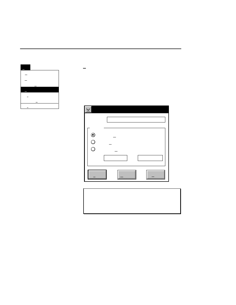
SCF ViewIR
SCF ViewIR - File Menu
3-5
Printer...
Save as...
Save
Print setup...
File
Close F3
Open...
Print... Ctrl+P
Print...
Ctrl + P
Opens the Print dialog box, where you can select the portion of
the SCF file to be printed. The chromatograms currently
displayed in the window, the entire file, or a range of bases can
be printed. Click on the appropriate radio button, and enter the
range of bases to be printed, if needed. Click
to send the
file to the printer.
Cancel
Help
Printer HP LaserJet4
Range
Current Window
Entire File
From 1
Selected Bases
To 501
NOTE: If you have not selected a system printer, the
Select printer dialog (see below) will appear before the
Print dialog. Select a printer, click
O K
, and the Print
dialog will appear.
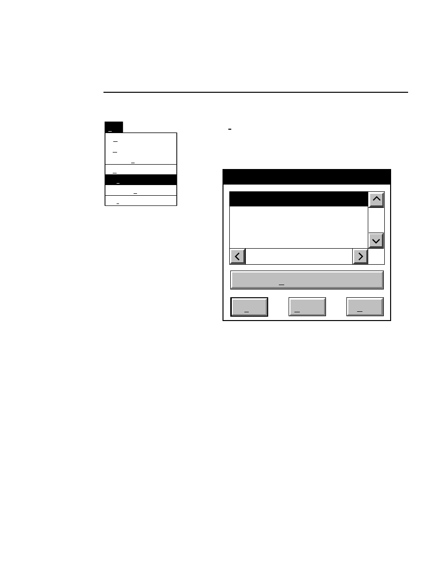
Section 3
3-6
SCF ViewIR - File Menu
Print... Ctrl+P
Save as...
Save
Print setup...
File
Close F3
Open...
Printer...
Printer...
Opens the Select printer dialog box, where you can select any
one of the system printers currently connected to the computer.
You must select a printer before printing an SCF file.
Select printer
Printer HPLJ4
Printer Alden Thermal
Cancel
OK
Help
Job properties
Select the desired printer and click
OK
. If you want to change
any of the job properties (i.e., number of copies, page
orientation, form size, etc.) click on the
Job properties
button.
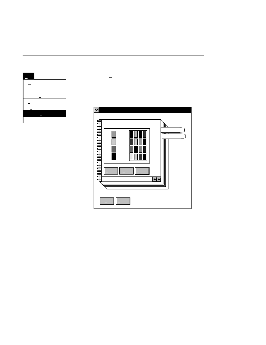
SCF ViewIR
SCF ViewIR - File Menu
3-7
Printer...
Print... Ctrl+P
Save as...
Save
File
Close F3
Open...
Print setup...
Print setup...
Opens the Print Setup dialog box, where you can change the
horizontal magnification of the printed chromatograms and the
color(s) of the chromatograms, if you are printing to a color
printer.
Print setup
Color Setup
OK
Cancel
Page
Colors
Help
Reset
Default
A
G
C
T
To change the color of the curve for one or more of the base
types, follow these steps:
1.
If you have not already done so, select a color printer
attached to the system.
2.
In the Print Setup dialog, colors that are supported by the
printer selected in step 1 will be shown under Color
Setup, to the right of the currently active colors for each
base type.

Section 3
3-8
SCF ViewIR - File Menu
3.
Colors are changed by dragging a new color from the
large palette onto the "thumbnail" palette to the right of
each base type.
4.
Click the right mouse button on the desired color in the
palette, and drag it off of the palette. The cursor will
change to a circle with a line through it.
5.
Drag the new color over top of the thumbnail next to the
A, T, G, or C base types. Release the mouse button, and
the displayed color will be replaced with the new color.
Click
OK
to dismiss the Print Setup dialog.
Changing the Horizontal Magnification
When printing the entire file, or a specified number of bases,
the original data points are mapped to one pixel on the printed
page. At the default magnification (1:1), the curves will
appear very small, and the base calls may overlap. To increase
the horizontal magnification, click on the Page notebook tab,
and use the scroll arrows to increase the magnification. The
curves will elongate horizontally, and the base calls will
become more legible.
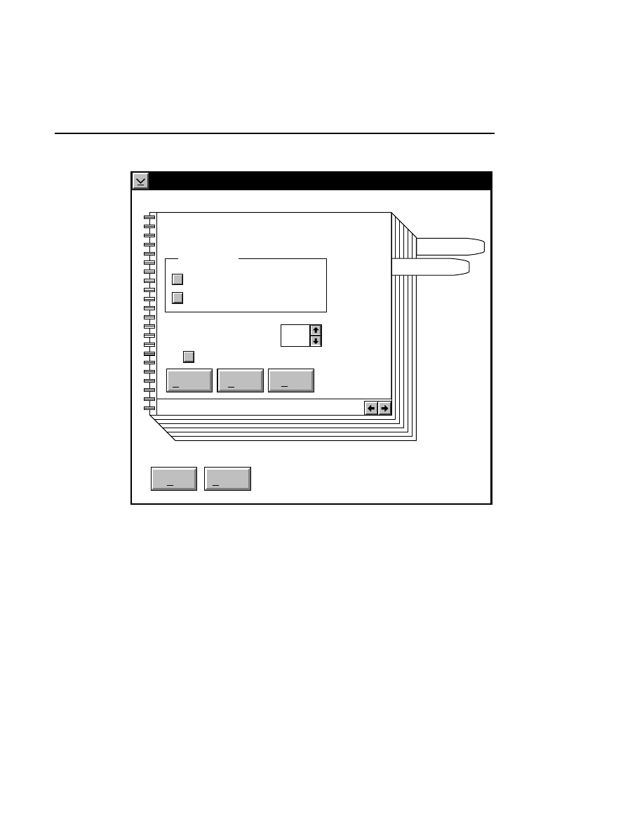
SCF ViewIR
SCF ViewIR - File Menu
3-9
Print setup
Page Setup
Used only for 'Entire file' and 'Selected bases'.
Print bases
OK
Cancel
Page
Colors
Default
Reset
Help
Non-editable
Editable
Horiz. magnify [1-20]: 1
Scale magnification to font
✓
✓
You have two options when scaling your printed output;
selecting a magnification manually, or letting SCF ViewIR
choose the magnification at which the base calls will not
overlap. The magnification options can be found in the Print
Setup dialog. Choose the 'Scale magnification to font' check
box to let SCF ViewIR select the optimum magnification.
When this option is selected, and you select a printer in the
Printing Options dialog box, SCF ViewIR queries this printer
as to the smallest available font size that can be printed. Fonts
will be scaled up until base calls begin to overlap on the

Section 3
3-10
SCF ViewIR - File Menu
printed page. The largest font size that can be printed with no
overlap will be chosen.
You may also notice that the number of printed bases per page
varies between different printers. As the resolution of the
printer increases, the size of the printed output decreases,
resulting in more bases being printed on a page. For example,
a 600 d.p.i. printer will print the SCF curves at half the size of
a 300 d.p.i. printer, resulting in more printed bases per page.
Note, too, that in portrait mode, the header takes up less space
proportionately than when printed in landscape mode. For this
reason, printing in portrait mode will also result in slightly
more bases being printed on the page. Thus, to obtain the
most bases per printed page, follow these guidelines:
1.
Select a printer with the highest possible resolution.
2.
Select portrait mode in the Job settings of the Printing
Options dialog.
3.
Choose a horizontal magnification as low as possible.
Note, however, that manually selecting a magnification
level may result in some overlap of the sequence text.
Close
Use the Close menu choice to quit SCF ViewIR.
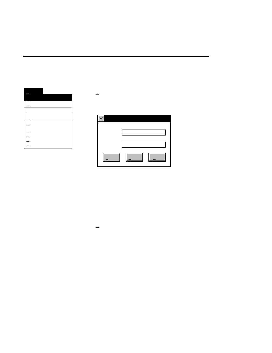
SCF ViewIR
SCF ViewIR - Options Menu
3-11
Options Menu
Comments...
Options
Markers Ctrl+M
1: X-mag + 1 +
2: X-mag - 1 -
3: Y-mag + 1 Ctrl++
4: Y-mag - 1 Ctrl+-
Search...
IUPAC codes...
Colors...
Search...
Opens the Search dialog box, where you can locate a base or
string of bases in the sequence text.
Search
Help
Search
Bases: ATCCAGTTACGGTAA
Find: |
Cancel
Enter a base or string of bases in the 'Find' field and press
Search
to locate the base(s). The base(s), if found, will be
highlighted in the sequence text above the chromatogram. If
the text is not found, a message will appear. NOTE: The
text in the 'Find' field is case sensitive. Use lowercase
letters to search for ambiguities other than 'N' or 'X'.
Comments...
Opens the Comments dialog box, which contains information
about the current SCF file, including the name of the
associated image and sample files, and whether or not the SCF
file was created using raw data or data that have been corrected
for differences in lane mobility ("shifted").
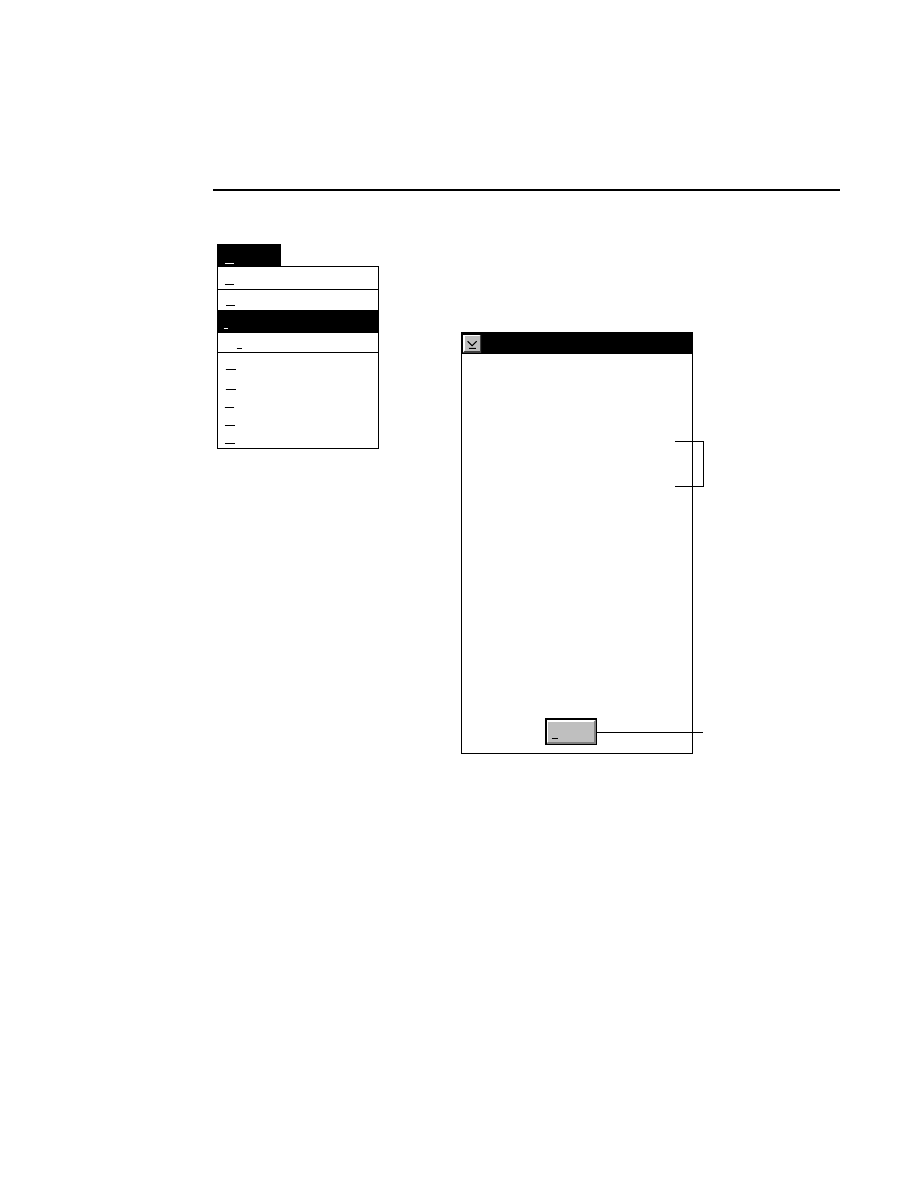
Section 3
3-12
SCF ViewIR - Options Menu
Comments...
Options
Markers Ctrl+M
1: X-mag + 1 +
2: X-mag - 1 -
3: Y-mag + 1 Ctrl++
4: Y-mag - 1 Ctrl+-
Search...
IUPAC codes...
Colors...
IUPAC codes...
Opens the Modified Ambiguity Code list, where you can
review the IUPAC codes for editing.
(*Modified) IUPAC Ambiguity Code
Dismiss
A
C
G
T
a
c
g
t
R
Y
M
K
W
S
B
D
H
V
N
Adenine
Cytosine
Guanine
Thymine (Uracil)
Questionable A
Questionable C
Questionable G
Questionable T (U)
A or G
C or T (U)
C or A
G or T (U)
A or T (U)
C or G
C or G or T (U)
G or A or T (U)
A or C or T (U)
A or C or G
Either A, C, G, or T (U)
*
*
*
*
Additional codes
added by LI-COR
Press here to close the
IUPAC Code dialog box.
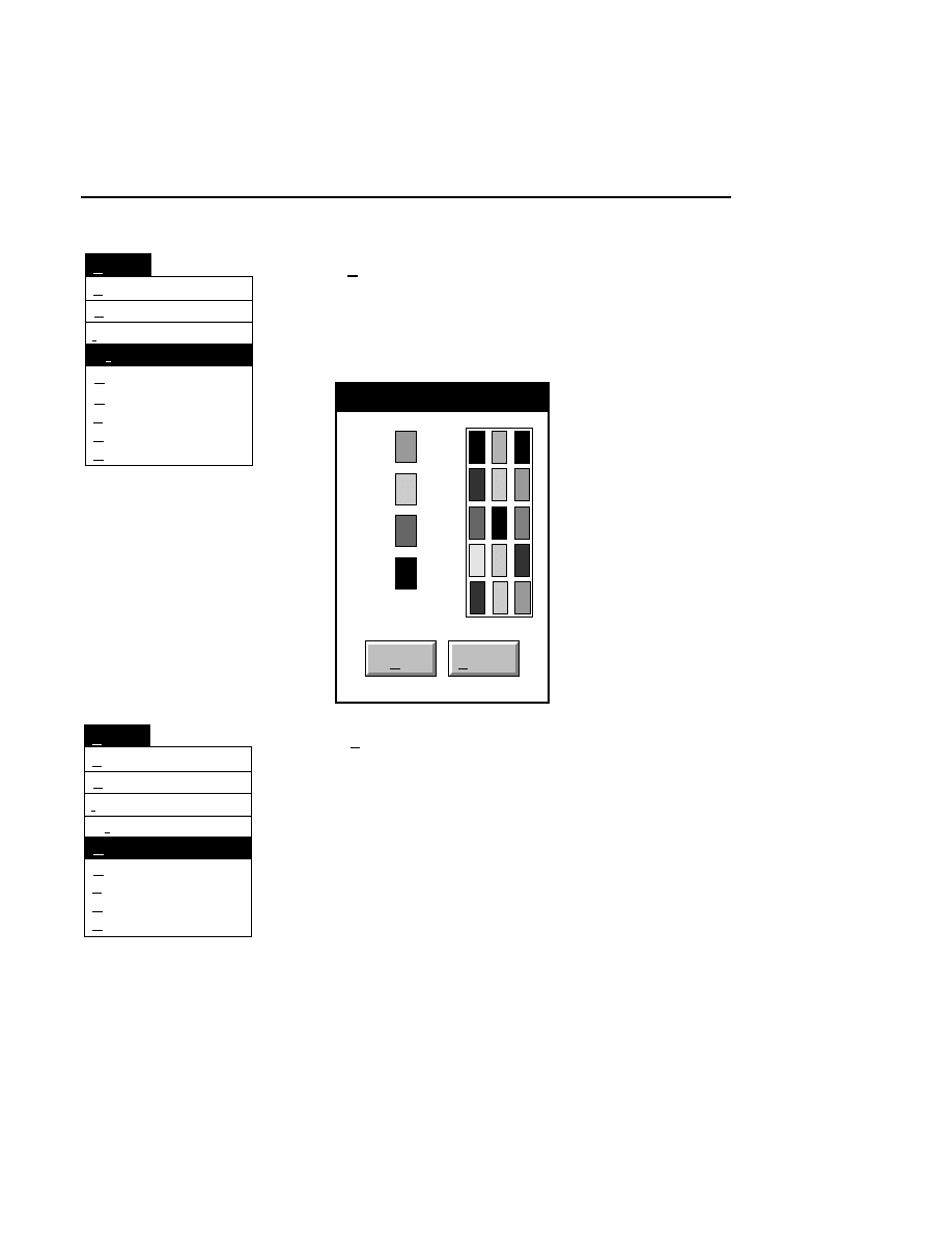
SCF ViewIR
SCF ViewIR - Options Menu
3-13
Comments...
Options
Markers Ctrl+M
1: X-mag + 1 +
2: X-mag - 1 -
3: Y-mag + 1 Ctrl++
4: Y-mag - 1 Ctrl+-
Search...
IUPAC codes...
Colors...
Colors...
Opens the Base and Trace colors dialog box, where you can
change the colors of the base text and SCF curves. Note that
the colors selected are for display only; colors can be changed
for printed output in the Printer Setup dialog box.
Base and Trace colors
OK
Cancel
A:
C:
G:
T:
Comments...
Options
Markers Ctrl+M
1: X-mag + 1 +
2: X-mag - 1 -
3: Y-mag + 1 Ctrl++
4: Y-mag - 1 Ctrl+-
Search...
IUPAC codes...
Colors...
Markers
Ctrl + M
Markers that show the location of the actual data points on the
chromatograms can be toggled on and off. Note that the
markers may not be visible at normal magnification. Enlarge
the chromatograms by pressing + (plus) on the numeric keypad
(to enlarge the chromatogram horizontally) or Ctrl + (+) on the
numeric keypad (to enlarge the chromatogram vertically).
Press - (minus) or Ctrl + (-) to reduce the chromatograms
horizontally and/or vertically, respectively.
Section 3
3-14
SCF ViewIR - Options Menu
Comments...
Options
Markers Ctrl+M
1: X-mag + 1 +
2: X-mag - 1 -
3: Y-mag + 1 Ctrl++
4: Y-mag - 1 Ctrl+-
Search...
IUPAC codes...
Colors...
X-mag + 1
+
Enlarges the chromatogram in the horizontal dimension.
X-mag - 1
-
Reduces the chromatogram in the horizontal dimension.
Y-mag + 1
Ctrl + +
Enlarges the chromatogram in the vertical dimension.
Y-mag - 1
Ctrl + -
Reduces the chromatogram in the vertical dimension.

SCF ViewIR
SCF ViewIR - Editing the Sequence Text
3-15
Editing the Sequence Text
The uppermost text field containing the sequence text in the
SCF ViewIR window is an editable field in which you can
change, insert, or delete the sequence text. The sequence text
can also be "clipped" at two locations, which allows some
analysis software programs to ignore base calls that are outside
of the left and right clip positions.
Edits and clip positions are not saved unless you save the data
to a new file.
■
To edit the bases:
1.
Move the pointer to the desired location in the editable
text field. A vertical line will appear.
2.
Click the left mouse button. If you click on the actual
base location, the sequence text will be highlighted, as
shown below. Highlighted text can be deleted, or
changed by pressing A,T,G, or C, or any of the IUPAC
ambiguity codes.
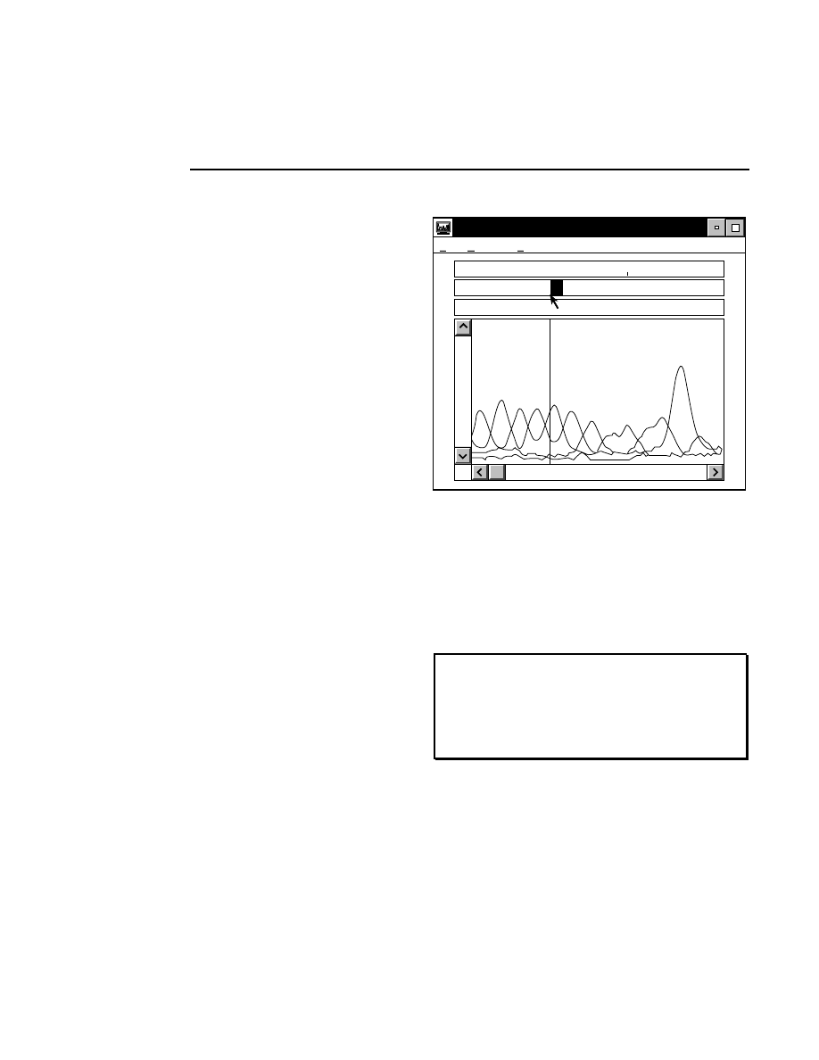
Section 3
3-16
SCF ViewIR - Editing the Sequence Text
C:\DNA4200\TEST01.SCF <501 Bases>
File Options Help
C G G C
C
A G T G C C A T
C G G C C A G T G C C A T
10
Highlighted text.
3.
If you click anywhere other than the actual base location,
a thin text insertion cursor will appear. Press A,T,G, or C,
or any of the IUPAC codes to insert sequence text at that
location.
4.
Press
Esc
to abort the Edit operation.
NOTE: To highlight sequence text, it may be helpful
to enlarge the chromatogram (by pressing + and/or
Ctrl + (+)) and/or turn on the markers. Click the
cursor near the lower lefthand corner of the sequence
text.
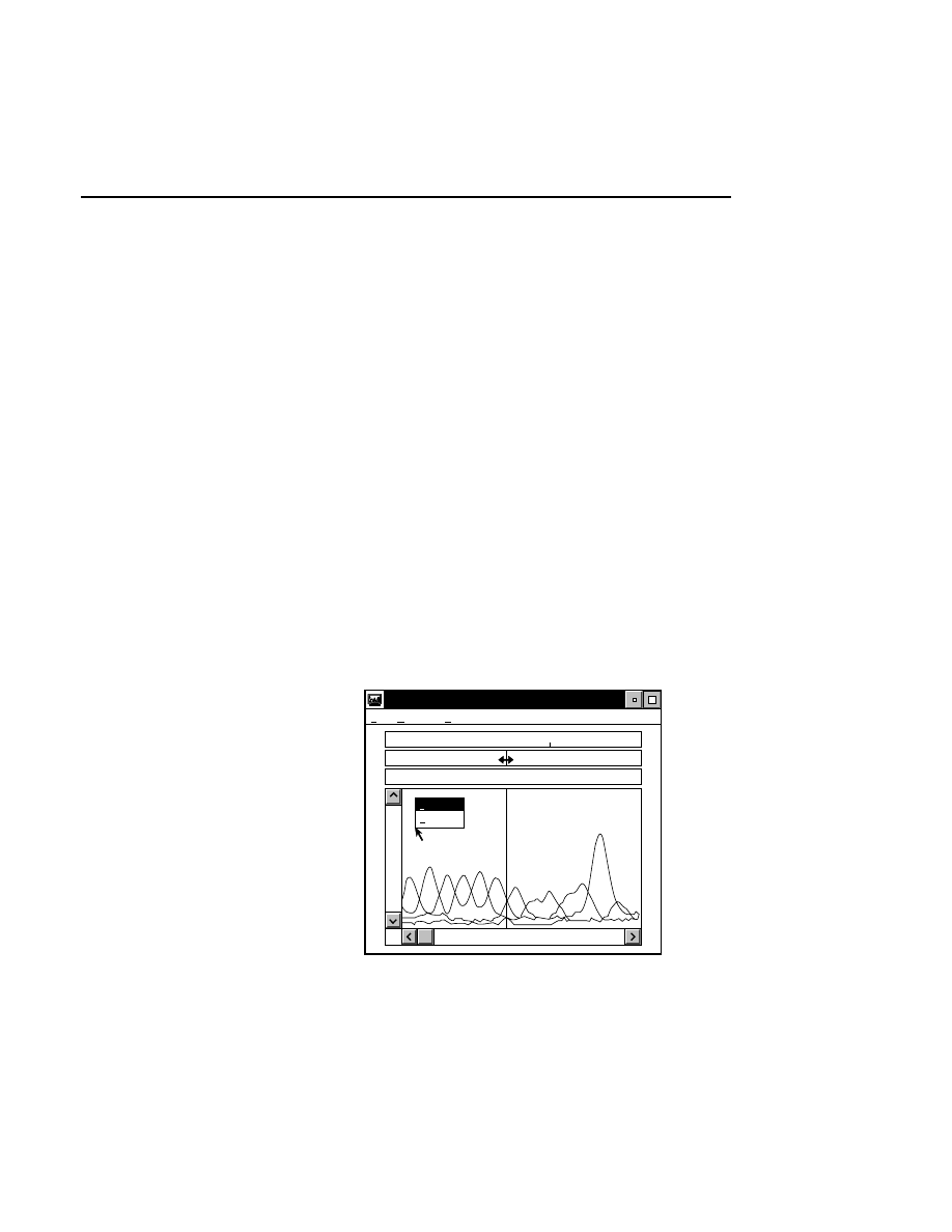
SCF ViewIR
SCF ViewIR - Clipping the Sequence Text
3-17
Clipping the Sequence Text
A left and/or right clip position can be defined in the editable
sequence text field. Clipped bases display and print in grey.
■
To clip bases:
1.
Press the right mouse button, or press Shift + F10 to
display a pop-up menu.
2.
Select the desired side to clip (Right or Left). The pointer
will change to a double arrow head.
3.
Move the pointer to the desired location in the editable
text field and press the left mouse button. The clipped
bases will be greyed out. In the graphic below, left clip
was chosen from the pop-up menu, and the double arrow
head cursor was placed between base numbers 6 and 7.
When the left mouse button is pressed, the sequence text
corresponding to bases 1 through 6 are clipped.
C:\DNA4200\TEST01.SCF <501 Bases>
File Options Help
C G G C C A
G T G C C A T
C G G C C A G T G C C A T
10
Right clip
Left clip
Left clip representation.

SCF PrintIR
4-1
SCF PrintIR
Table of Contents
page
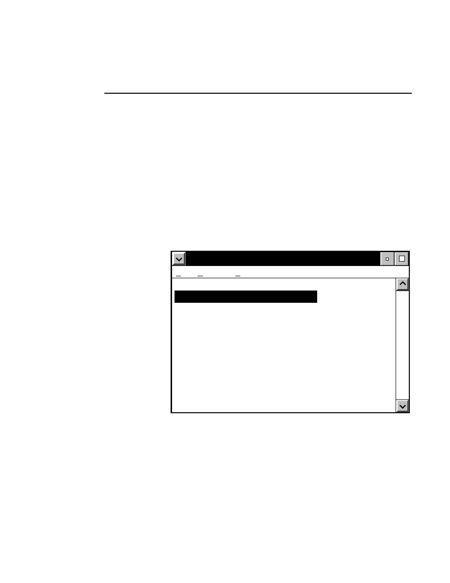
Section 4
4-2
SCF PrintIR
Introduction
SCF File PrintIR is a program that allows you to batch print
.SCF files created from LI-COR sample files with Image
Analysis or the SCF File Creation program.
The main SCF PrintIR window simply serves as a file list for
batch printing of one or more .SCF files. Files can be added or
deleted from this list using commands on the File menu.
Other commands allow you to set up the system printer and
retain or remove files from the list after they have been
printed.
PrintIR
File Options Help
C:\DNA4200\DATA\Test1.SCF
C:\DNA4200\DATA\042797S1.SCF
C:\DNA4200\DATA\Lab04.SCF
SCF PrintIR primary window.
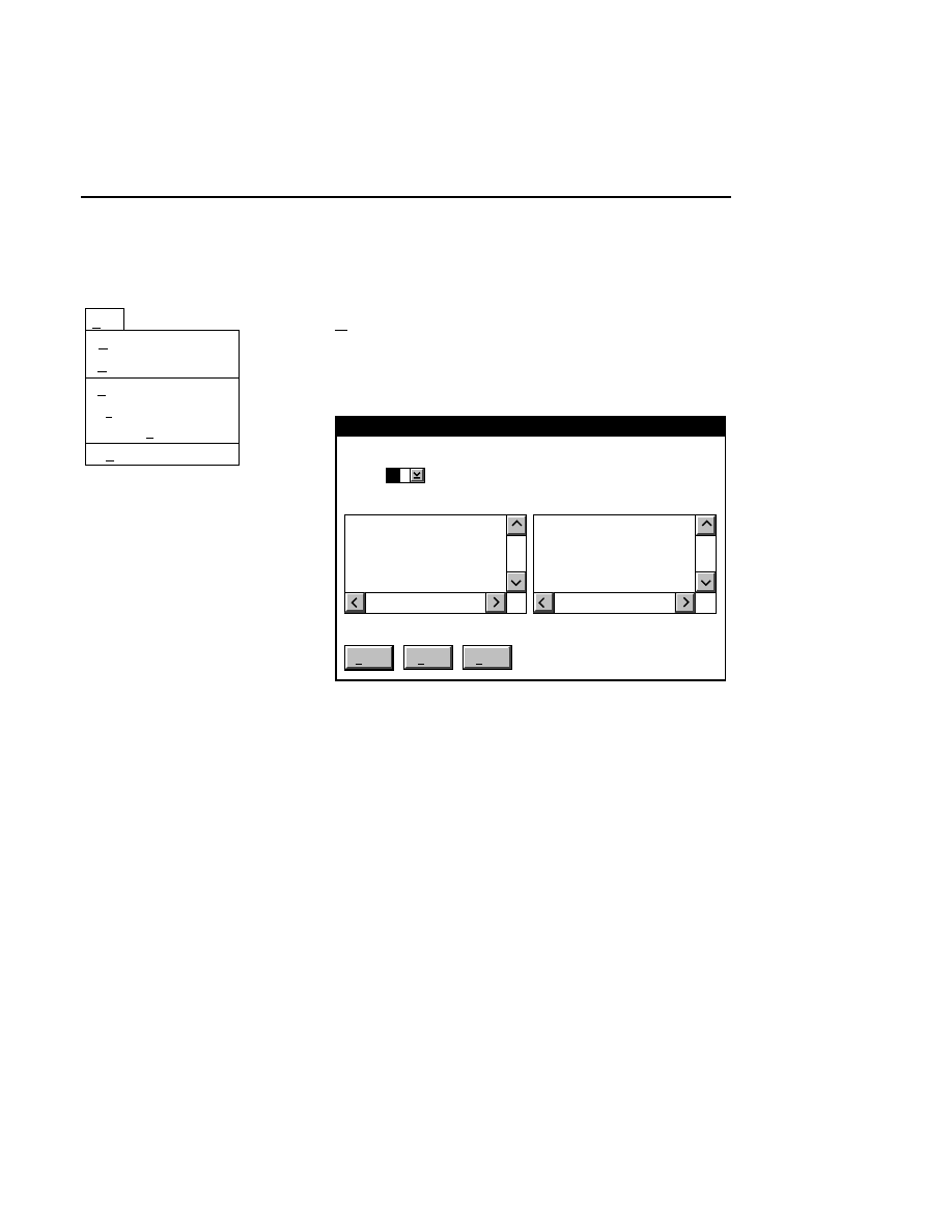
SCF PrintIR
SCF PrintIR - File Menu
4-3
File Menu
Printer...
Print... Ctrl+P
Delete Del
Print setup...
File
Exit F3
Add...
Add...
Select
Add
to select .SCF files to be added to the print list in
the primary window. The Add Files dialog box will be
displayed:
Add Files
Add
Help
Done
Path: C:\DNA4200\SCF
Drives:
Files:
..
Directories:
C
Test1.SCF
Use the Drives, Directories, and Files list boxes to locate the
files. Select the file(s) in the Files list box and press
Add
to
add the file to the print list.
When you have finished selecting files, press
Done
.
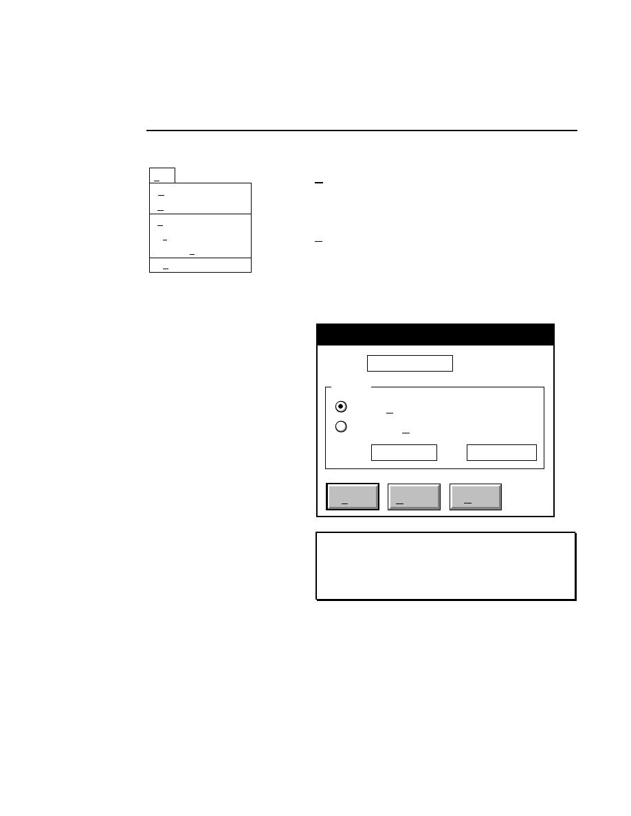
Section 4
4-4
SCF PrintIR - File Menu
Printer...
Print... Ctrl+P
Delete Del
Print setup...
File
Exit F3
Add...
Delete
Removes selected file names from the print list in the primary
window.
Print...
Ctrl + P
Opens the Print dialog box, where you can select the portion of
the SCF file to be printed. The entire file or a range of bases
can be printed. Click on the appropriate radio button, and
enter the range of bases to be printed, if needed. Click
to
send the file to the printer.
Cancel
Help
Printer: Printer HPLJ4
Range
Entire File
From 1
Selected Bases
To 501
NOTE: If you have not selected a system printer, the
Select printer dialog (see below) will appear before the
Print dialog. Select a printer, click
O K
, and the Print
dialog will appear.
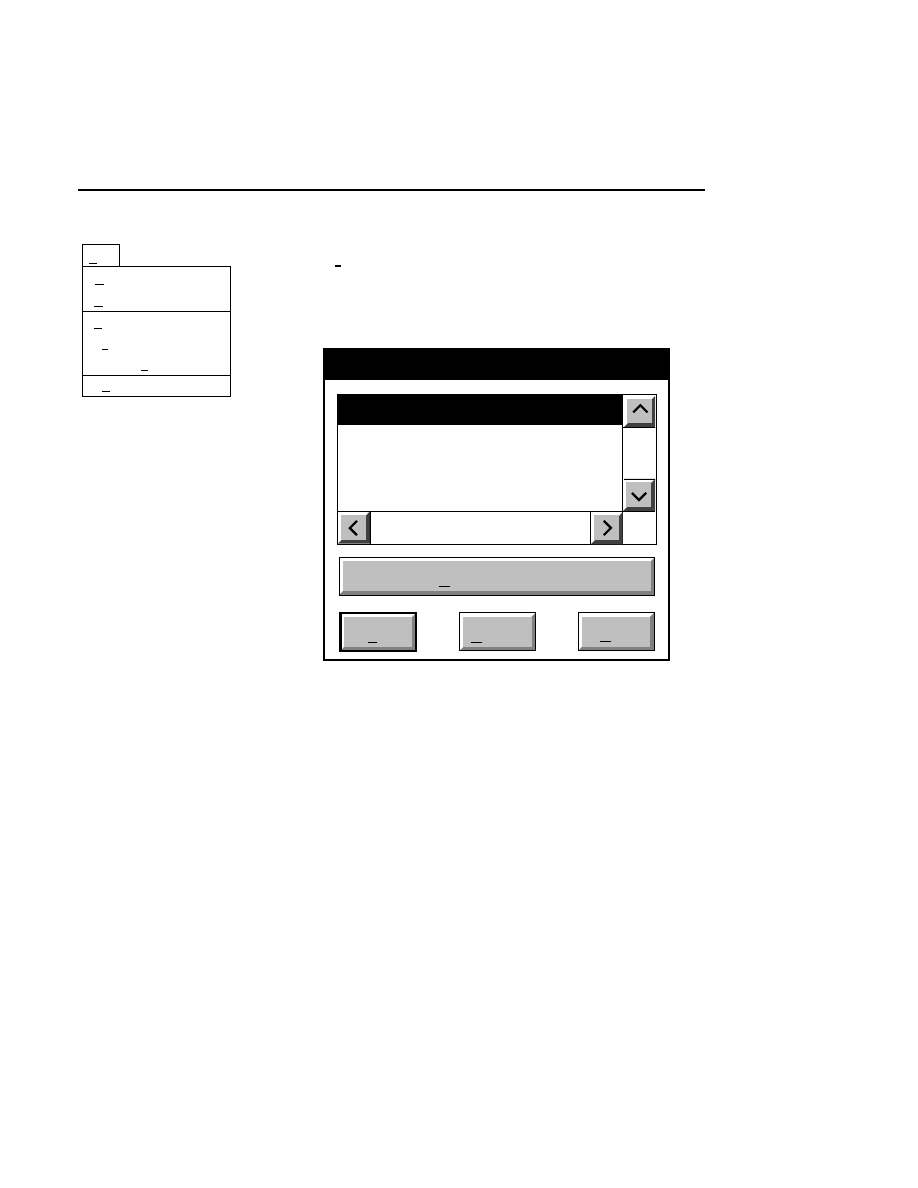
SCF PrintIR
SCF PrintIR - File Menu
4-5
Printer...
Print... Ctrl+P
Delete Del
Print setup...
File
Exit F3
Add...
Printer...
Opens the Select printer dialog box, where you can select any
one of the system printers currently connected to the computer.
You must select a printer before printing an SCF file.
Select printer
Printer HPLJ4
Printer Alden Thermal
Cancel
OK
Help
Job properties
Select the desired printer and click
OK
. If you want to change
any of the job properties (i.e., number of copies, page
orientation, form size, etc.) click on the
Job properties
button.
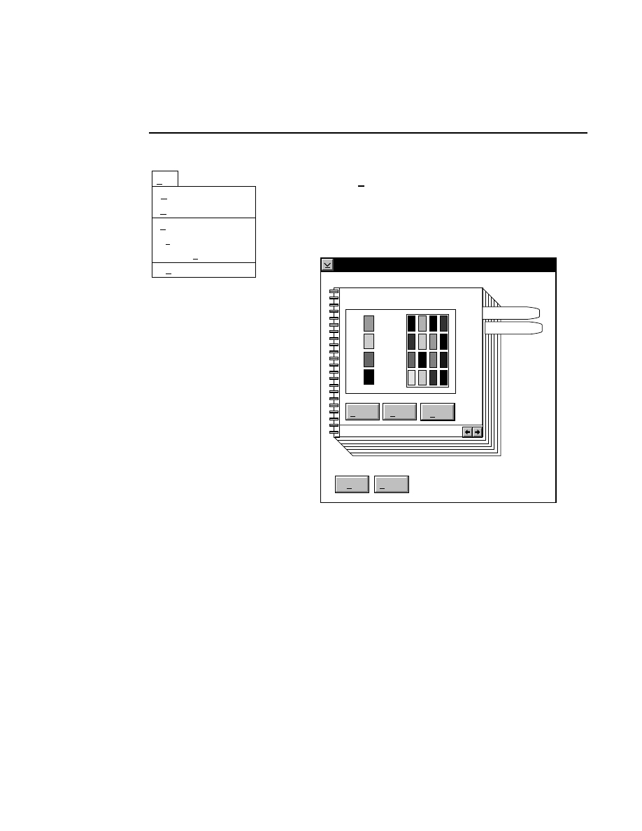
Section 4
4-6
SCF PrintIR - File Menu
Printer...
Print... Ctrl+P
Delete Del
Print setup...
File
Exit F3
Add...
Print setup...
Opens the Print Setup dialog box, where you can change the
horizontal magnification of the printed chromatograms and the
color(s) of the chromatograms, if you are printing to a color
printer.
Print setup
Color Setup
OK
Cancel
Page
Colors
Help
Reset
Default
A
G
C
T
To change the color of the curve for one or more of the base
types, follow these steps:
1.
If you have not already done so, select a color printer
attached to the system.
2.
In the Print Setup dialog, colors that are supported by the
printer selected in step 1 will be shown under Color
Setup, to the right of the currently active colors for each
base type.

SCF PrintIR
SCF PrintIR - File Menu
4-7
3.
Colors are changed by dragging a new color from the
large palette onto the "thumbnail" palette to the right of
each base type.
4.
Click the right mouse button on the desired color in the
palette, and drag it off of the palette. The cursor will
change to a circle with a line through it.
5.
Drag the new color over the thumbnail next to the A, T,
G, or C base types. Release the mouse button, and the
displayed color will be replaced with the new color.
Click
OK
to dismiss the Print Setup dialog.
Changing the Horizontal Magnification
When printing the entire file, or a specified number of bases,
the original data points are mapped to one pixel on the printed
page. At the default magnification (1:1), the curves will
appear very small, and the base calls may overlap. To increase
the horizontal magnification, click on the Page notebook tab,
and use the scroll arrows to increase the magnification. The
curves will elongate horizontally, and the base calls will
become more legible.
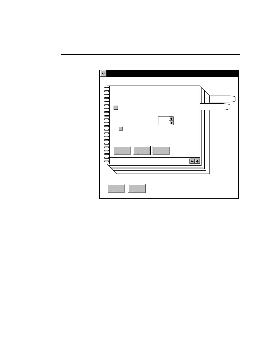
Section 4
4-8
SCF PrintIR - File Menu
Print setup
Page Setup
Used only for 'Entire file' and 'Selected bases'.
OK
Cancel
Page
Colors
Default
Reset
Help
Print bases
Horiz. magnify [1-20]: 1
Scale magnification to font
✓
✓
You have two options when scaling your printed output;
selecting a magnification manually, or letting SCF PrintIR
choose the magnification at which the base calls will not
overlap. The magnification options can be found in the Print
Setup dialog. Choose the 'Scale magnification to font' check
box to let SCF PrintIR select the optimum magnification.
When this option is selected and you choose a printer in the
Printing Options dialog box, SCF PrintIR queries this printer
as to the smallest available font size that can be printed. Fonts
will be scaled up until base calls begin to overlap on the

SCF PrintIR
SCF PrintIR - File Menu
4-9
printed page. The largest font size that can be printed with no
overlap will be chosen.
You may also notice that the number of printed bases per page
varies between different printers. As the resolution of the
printer increases, the size of the printed output decreases,
resulting in more bases being printed on a page. For example,
a 600 d.p.i. printer will print the SCF curves at half the size of
a 300 d.p.i. printer, resulting in more printed bases per page.
Note, too, that in portrait mode, the header takes up less space
proportionately than when printed in landscape mode. For this
reason, printing in portrait mode will also result in slightly
more bases being printed on the page. Thus, to obtain the
most bases per printed page, follow these guidelines:
1.
Select a printer with the highest possible resolution.
2.
Select portrait mode in the Job settings of the Printing
Options dialog.
3.
Choose a horizontal magnification as low as possible.
Note, however, that manually selecting a magnification
level may result in some overlap of the sequence text.
Exit
Use the Exit menu choice to quit SCF PrintIR.
Section 4
4-10
SCF PrintIR - Options Menu
Options Menu
Options
Remove after printing
Remove after printing
Removes highlighted files from the print list after they have
been printed. If this option is not selected, files will remain in
the print list after printing.

SCF PrintIR
SCF PrintIR - Help Menu
4-11
Help Menu
Help for help
Extended help
Keys help
Help index
About...
Help
Help for help
Opens a window describing the use of help screens.
Extended help
Displays a brief overview of the SCF PrintIR program.
Keys help
Gives a description of the keyboard shortcuts for SCF PrintIR.
Help index
Contains a listing of topics for which help information is
available. Double-click on the listing to open the help
information for the selected topic.
About...
Displays the SCF PrintIR startup screen, which shows the
software version number of the program.

Error Messages
A-1
Error Messages
You may occasionally encounter error messages while using
the Base ImagIR Data Collection and/or Image Analysis
programs. Press the
Help
button (if available) or the
F1
key
when an error message is displayed to see a description and
possible solutions to the problem. Some of the common error
messages are described below. Others are possible, but they
may require more complex solutions.
Autosequencing Setup Error
This message appears if you attempt to initiate Auto-
sequencing without first defining the sample lanes and
marking at least one base. Click
OK
, mark a base, and retry
the operation.
Bad Data (Open Configuration)
This error occurs if you try to open a file that is not the correct
type. For example, if a file is given the extension .IMG, but is
not a LI-COR image file, Base ImagIR will not recognize it
and this error message will appear. Similarly, opening a file
with a .COL or .ANL extension that is not a LI-COR config-
uration file will cause this error.
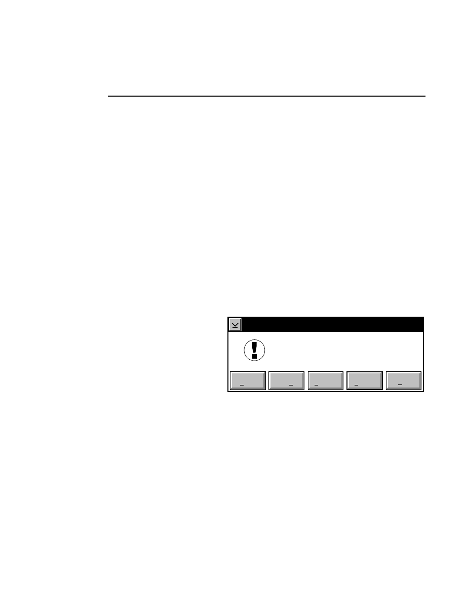
Appendix A
A-2
Error Messages
Disk is Full
The disk does not contain enough free space for the file that is
being written. Insert another disk or change drives. Use the
CHKDSK command in the OS/2 Window to verify the amount
of memory available on the disk.
Disk problem
This message commonly appears if the floppy or optical disk
is not in the drive specified. Insert the disk and retry the
command.
Exit Warning
EXIT-WARNING!
C:\DNA4200\TEST.SMP
has changed.
Do you want to save it?
Save as...
Save
Discard
Cancel
Help
This message appears if you try to exit the Image Analysis
program without saving the sample file that you were working
on. Use the
Save
or
Save as
buttons to save the sample file.
If the file is untitled, you will be prompted to name the file.
Choose
Discard
to close the file without saving it. Choose
Cancel
to dismiss the Exit Warning message box without
closing the program.

Error Messages
Error Messages
A-3
Failed to change to new directory
A directory in the specified path does not exist. Retry the
operation by entering the proper path name.
Failed to make new directory
An attempt to make a new directory has failed. This error is
usually caused by an invalid directory name or by trying to
create a subdirectory in a directory that is full. Enter a new
name for the directory, or change the path to which it will be
created.
File not found
The file listed in a dialog box does not exist in the directory of
the specified drive. Enter the correct file name or change the
specified path.
Invalid drive specified
The drive specified is invalid or does not exist. Enter the
proper drive specifier and retry the command. Click on the
OS/2 Drives icon to view the available drives on the computer.

Appendix A
A-4
Error Messages
Invalid file name
Open Sample File
Invalid file name.
D:\TESTSAMPLE.SMP
OK
The file name specified is not valid. Check to be sure that the
name is the proper length, and that it does not contain any
illegal characters (e.g. " / \ : * ? | ). OS/2's High
Performance File System (HPFS) allows file names up to 254
characters in length; keep in mind, however, that removable
media such as optical or floppy disks only support 8-character
file names with a 3-character extension. If you plan to archive
files to optical or floppy disks, you will find that transferring
and retrieving files will be easier if you use 8-character names
when you name new files.
Error Messages
Error Messages
A-5
May be TOO CLOSE
Spacing Warning
May be TOO CLOSE
OK
This message may appear during manual or semi-automatic
sequencing to alert you that the vertical spacing between the
band just marked and the previous band is less than one half of
the current value set for the band spacing. In general, the
center-to-center distance between bands will remain relatively
stable if the gel electrophoresis is conducted at constant
power. This message does not necessarily indicate a problem,
however. Changes in the electrophoresis operating para-
meters, or electrophoresis anomalies can cause sudden
changes in the band spacing. This message is intended to alert
you to a possible miscall (marking a "ghost" band, for
example). If the message appears continuously, you may want
to adjust the band spacing, using the Auto Band Spacing or
Band Spacing menu choices.
Appendix A
A-6
Error Messages
May be TOO FAR
Spacing Warning
May be TOO FAR
OK
This message may appear during manual or semi-automatic
sequencing to alert you that the vertical spacing between the
band just marked and the previous band is more than one and
one half times the current value set for the band spacing. In
general, the band center-to-band center distance will remain
relatively stable if the gel electrophoresis is conducted at
constant power. This message does not necessarily indicate a
problem, however. Changes in the electrophoresis operating
parameters, or electrophoresis anomalies can cause sudden
changes in the band spacing. This message is intended to alert
you to a possible gap (a missing band) in the image. If the
message appears continuously, you may want to adjust the
band spacing, using the Auto Band Spacing or Band Spacing
menu choices.
Error Messages
Error Messages
A-7
New Warning
New
OK
Cancel
Erase the Log file?
?
If you select New from the File menu in the Log Notepad
when there is text already present, this message will appear.
Select
OK
to erase all text in the Notepad. Select
Cancel
to
close the error dialog without erasing the Notepad.
Open Configuration
Open Configuration
Unable to open file.
Using internal defaults
OK
The default configuration file DEFAULT.ANL has been
deleted, or has been moved out of the DNA4200 directory.
Internal default values will be loaded into the Configuration
window as an untitled configuration file. This untitled file can
be saved as the new DEFAULT.ANL file by selecting Save as
from the Configuration window File menu, and entering
DEFAULT.ANL, or by selecting the Save as DEFAULT
menu choice.
Appendix A
A-8
Error Messages
Open Warning
OPEN-WARNING!
Untitled
has changed.
Do you want to save it?
Save as...
Save
Discard
Cancel
Help
This message appears if you choose New Sample from the File
menu without saving the sample file you were working on.
Use the
Save
or
Save as
buttons to save the sample file. If
the file is untitled, you will be prompted to name the file.
Choose
Discard
to close the file without saving it. Choose
Cancel
to dismiss the Open Warning message box without
opening a new sample.
Path not found
This message appears if a file or path name entered into a text
entry field does not exist in the directory of the specified drive.
Re-enter the file name and/or path with the correct name(s).
Save Configuration (Overwrite?)
An overwrite message is displayed if the file name you have
typed already exists. If you want to overwrite the file click on
the
Yes
button.
Error Messages
Error Messages
A-9
Warning: File Changed
Warning: File Changed
Configuration File has changed.
Save as...
Save
Discard
Cancel
Help
The Configuration file that you have been using has changed
but has not been saved. Use the
Save
or
Save as
buttons to
save the file, or choose
Discard
to close the file without
saving the changes.
Appendix A
A-10
Error Messages
Width Warning (Zero lane width defined)
The lane defined on the image file is too narrow. This can
happen if you inadvertently click and release the mouse button
without dragging the lane marker. In the Lane Definition
dialog box, double-click on the letter of the lane to define
again, or click
Reset
and start over.
Configuration Warning
Open Configuration
Recreating the configuration
with Default settings.
OK
The default configuration file DEFAULT.ANL has been
deleted, or has been moved out of the DNA4200 directory.
Internal default values have been loaded into the
Configuration window as an untitled configuration file. If you
try to exit the Image Analysis program without saving this
configuration file, and select
Cancel
in the resulting warning
box, this message will appear. This is because when the
program was exited, the configuration file was removed from
memory. When
Cancel
is selected, the configuration file must
be recreated from the internal defaults.
Document Outline
- Welcome to Base ImagIR
- Data Collection
- Image Analysis
- Image Manipulation
- Quick SequencIR
- SCF File Creation
- SCF ViewIR
- SCF PrintIR
- Appendix A. Error Messages
Wyszukiwarka
Podobne podstrony:
KSRG ref
ref 2004 04 26 object pascal
emocje niespojne-ref, Onedrive całość, Rok I, II sem, Psychologia emocji i motywacji, Streszczenia
5366 Ref 22 id 41421 Nieznany (2)
BI blackrobodog
Rodzina ref
ref Komisja Edukacji Narodowej
emocje spojne-ref, Onedrive całość, Rok I, II sem, Psychologia emocji i motywacji, Streszczenia
BI robutler
5 racemiczny11-bi-2-naftol, Preparatyka organiczna
ref soc 251, Dokumenty(2)
aiso instrukcja dla?bili lab 3
Monia ref
BI od Oli Foss
wrażenia ref
BI część 2
Ref Rola i budowa skory
więcej podobnych podstron