41
In This Chapter
6
Creating Parametric
Sketches
Autodesk
®
Mechanical Desktop
®
automates your design
and revision process using parametric geometry.
Parametric geometry controls relationships among
design elements and automatically updates models and
drawings as they are refined.
The sketch is the basic design element that defines the
approximate size and shape of features in your part. As
the name implies, a sketch is a loose approximation of
the shape that will become a feature. After a sketch is
solved, you apply parametric constraints to control its
shape.
After you learn to create sketches, move on to chapter 2
to learn how to add constraints to sketches.
■
Analyzing a design and creating a
strategy for sketching
■
Text sketch profiles
■
Open profile sketches
■
Closed profile sketches
■
Path sketches
■
Cut line sketches
■
Split line sketches
■
Break line sketches

42
|
Chapter 6
Creating Parametric Sketches
Key Terms
Term
Definition
2D constraint
Defines how a sketch can change shape or size. Geometric constraints control the
shape and relationships among sketch lines and arcs. Dimensional constraints
control the size of sketch geometry.
closed loop
A polyline entity, or group of lines and arcs that form a closed shape. Closed loops
are used to create profile sketches.
closed profile
A constrained sketch that is a cross section or boundary of a shape, such as an
extrusion, a revolved feature, or a swept feature.
construction geometry
Any line or arc created with a noncontinuous linetype. Using construction
geometry in paths and profiles may mean fewer constraints and dimensions are
needed to control size and shape of symmetrical or geometrically consistent
sketches.
cut line
Used to specify the path of a cross-section drawing view. Unlike a profile sketch,
the cut line sketch is not a closed loop. There are two types of cut line sketches—
offset and aligned.
feature
An element of a parametric part model. You can create extruded features,
revolved features, loft features, and swept features using profiles and paths. You
can also create placed features like holes, chamfers, and fillets. You combine
features to create complete parametric part models.
nested loop
A closed loop that lies within the boundary of another closed loop. Nested loops
are used to create more complex profile sketches.
open profile
A profile created from one or more line segments sketched to form an open
shape. Open profiles are used in bend, rib, and thin wall features.
path sketch
A constrained sketch that is a trajectory for a swept feature.
sketch
A planar collection of points, lines, arcs, and polylines used to form a profile, path,
split line, break line, or cutting line. An unconstrained sketch contains geometry
and occasionally dimensions. A constrained sketch, such as a profile, path, split
line, cut line, or break line that contains “real” and construction geometry, and is
controlled by dimensions and geometric constraints.
sketch tolerance
Tolerance setting that closes gaps smaller than the pickbox and snaps lines to
horizontal, vertical, parallel, or perpendicular.
split line
A sketch, either open or closed, used to split a part into two distinct parts. Also
known as a parting line.
text sketch profile
A profile created from a single line of text in a selected font and style. Text-based
profiles are used to emboss parts with text.

Basic Concepts of Parametric Sketching
|
43
Basic Concepts of Parametric Sketching
You create, constrain, and edit sketches to define a
■
Profile that governs the shape of your part or feature
■
Location for a bend feature in a part design
■
Path for your profile to follow
■
Cut line to define section views
■
Split line to split a face or part
■
Break line to define breakout section views
After you create a rough sketch with lines, polylines, arcs, circles, and ellipses
to represent a feature, you solve the sketch. Solving a sketch creates a para-
metric profile, path, cut line, split line, or break line from your sketched
geometry.
When you solve a sketch, Mechanical Desktop converts it to a parametric
sketch by applying two-dimensional constraints to it, according to internal
rules. This reduces the number of dimensions and constraints you need to
fully constrain it. In general, a sketch should be fully constrained before it is
used to create a feature.
You can control the shape and size of the parametric sketch throughout mul-
tiple design revisions.
In this tutorial, you learn to create and solve sketches. Chapter 7, “Constrain-
ing Sketches,” introduces you to creating, modifying, and deleting the con-
straints and parametric dimensions that control a sketch.

44
|
Chapter 6
Creating Parametric Sketches
Sketching Tips
Some of these tips do not apply to this chapter, but you will see their useful-
ness when you use sketches to create complex parts.
Tip
Explanation
Keep sketches simple
It is easier to work with a single object than a multiple-object
sketch. Combine simple sketches for complex shapes.
Repeat simple shapes
If a design has repeating elements, sketch one and then copy or
array as needed.
Define a sketching
layer
Specify a separate layer and color for sketching. Your sketch is
visible with other part geometry but easy to identify when you
need to modify it.
Preset sketch
tolerances
Define characteristics, such as sketch precision and angular
tolerance of sketch lines, if the default values are not sufficient.
Draw sketches to size
When your sketches are roughly correct in size and shape, your
design is less likely to become distorted as dimensions or
constraints are added. Sketch a rectangle to serve as a boundary
for the base feature to set relative size. Sketch the feature, but
delete the rectangle before you create a profile.
Use PLINE
Whenever possible, use the PLINE command to create your
sketches. With PLINE, you can easily draw tangent lines and arcs.
Creating Profile Sketches
|
45
Creating Profile Sketches
In Mechanical Desktop, there are three types of profile sketches:
■
Text-based profiles, used to create parametric 3D text-based shapes
■
Open profile sketches, used to define features on parts
■
Closed profile sketches, used to outline parts and features
You can solve and apply parametric constraints and dimensions to all three
of these profile sketch types.
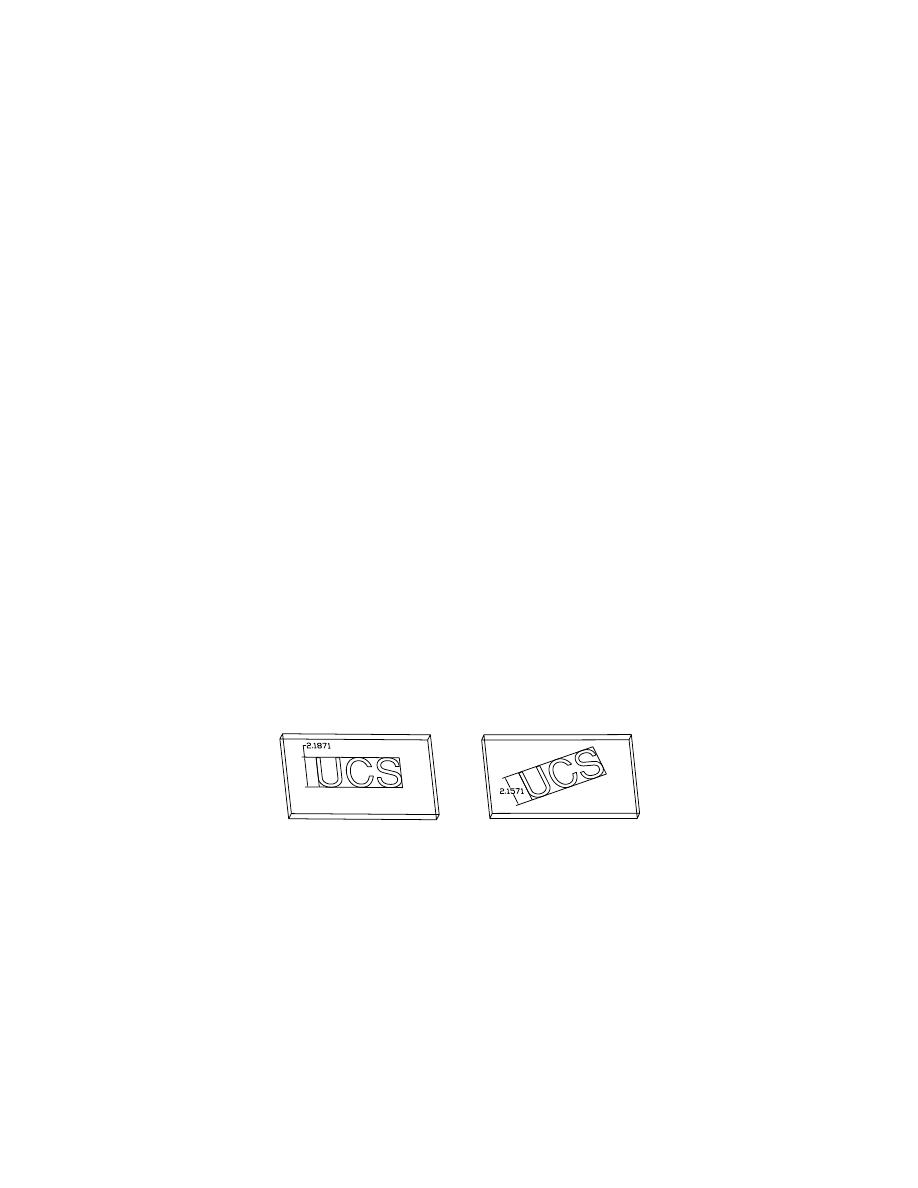
Creating Text Sketch Profiles
A text sketch profile is a line of text displayed in a rectangular boundary. You
extrude a text sketch profile to create the emboss feature on part models.
To create a text sketch profile, you use the command
AMTEXTSK
. A dialog box
opens where you can enter text and choose a font style and size, or you can
enter the information on the command line.
You define an anchor point for the rectangle on your part and a point to
define the height of the text. You have the option to define a rotation value
on the command line to position the text at an angle. As you move your cur-
sor to define the anchor and height points, the rectangular boundary scales
appropriately to accommodate the size of the text.
You can change the size of the text by changing the value of the height
dimension. You can apply typical parametric dimensions and constraints
between the rectangular boundary and other part edges or features.
When the text sketch profile is sized correctly and in the right position on
your part, you extrude it to create the emboss feature.
To learn more about using text sketch profiles in the emboss feature, see
“Creating Emboss Features” on page 140.
text sketch
text sketch with rotation defined
46
|
Chapter 6
Creating Parametric Sketches
Creating Open Profile Sketches
You can create an open profile from single or multiple line segments, and
solve it in the same way as you solve a closed profile.
An open profile constructed with one line segment is used to define the loca-
tion of a bend feature on a flat or cylindrical part model. To bend an entire
part, you sketch the open profile over the entire part. If you sketch the open
profile over a portion of a part, only that portion of the part bends.
Open profiles constructed with one or multiple line segments are extruded
to form rib features and thin features. For a rib feature, the open profile
defines the outline of the rib, and is sketched from the side view. For a thin
feature, the open profile defines the shape of a wall and is extruded normal
to the work plane.
To learn more about open profiles in features, see “Creating Bend Features”
on page 163, “Creating Rib Features” on page 133, and “Creating Thin Fea-
tures” on page 136.
Creating Closed Profile Sketches
A profile sketch is a two-dimensional outline of a feature. Closed profile
sketches are continuous shapes, called loops, that you construct from lines,
arcs, and polylines. You use closed profile sketches to create features with cus-
tom shapes (unlike standard mechanical features such as holes, chamfers,
and fillets).
Profile sketches can be created from a set of objects, or a single polyline, that
defines one or more closed loops. You can use more than one closed loop to
create a profile sketch if the loops are nested within each other.
You cannot create profile sketches with loops that are
■
Self-intersecting
■
Intersecting
■
Tangential
■
Nested more than one level deep
profile for rib feature
profile for bend feature
profile for thin feature
Creating Profile Sketches
|
47
In this section, you create three profile sketches.
Open the file sketch1.dwg in the desktop\tutorial folder. This drawing file is
blank but it contains the settings you need to create these profiles.
NOTE
Back up the tutorial drawing files so you still have the original files if you
make a mistake. See “Backing up Tutorial Drawing Files” on page 40.
Using Default Sketch Rules
Mechanical Desktop analyzes individual geometric elements, and operates
on a set of assumptions about how they should be oriented and joined.
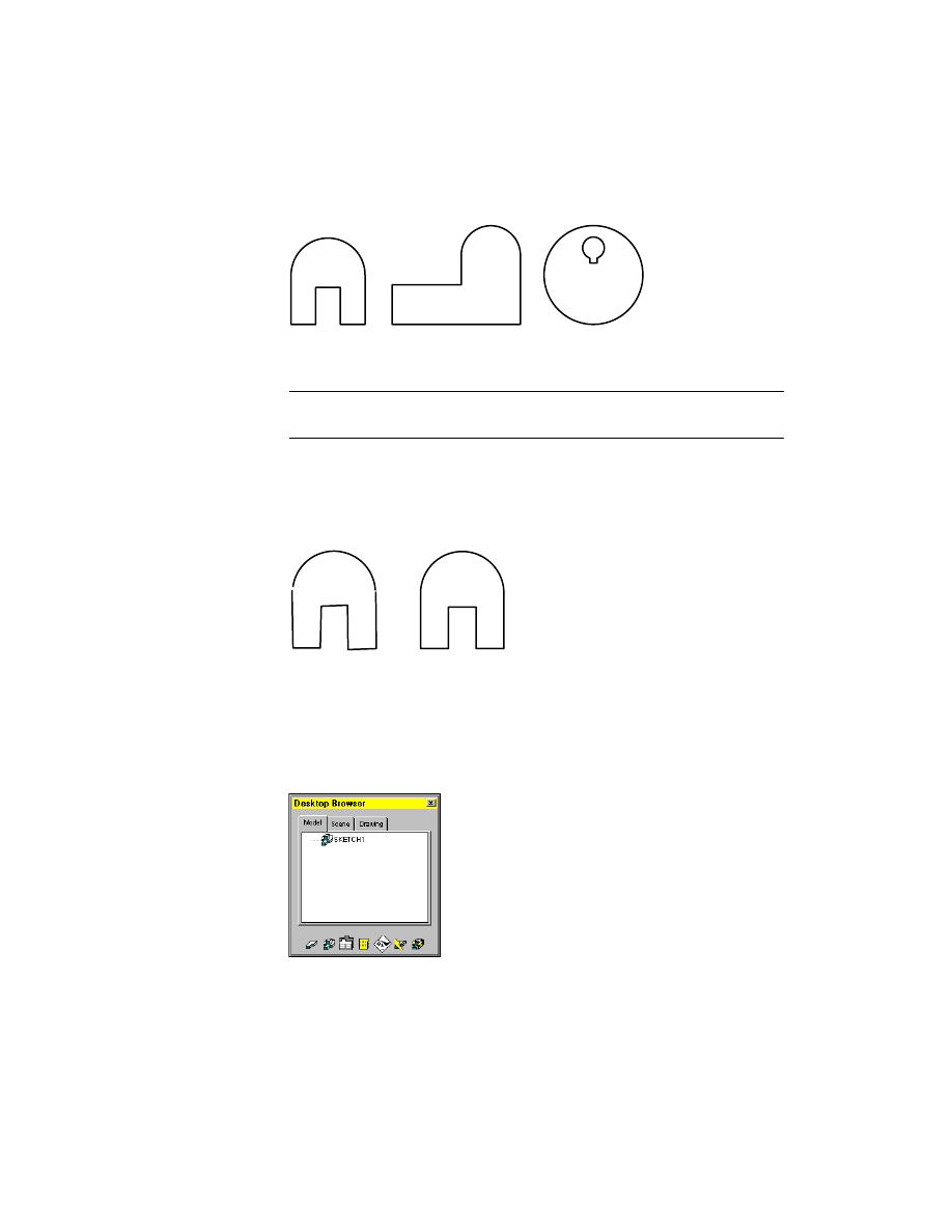
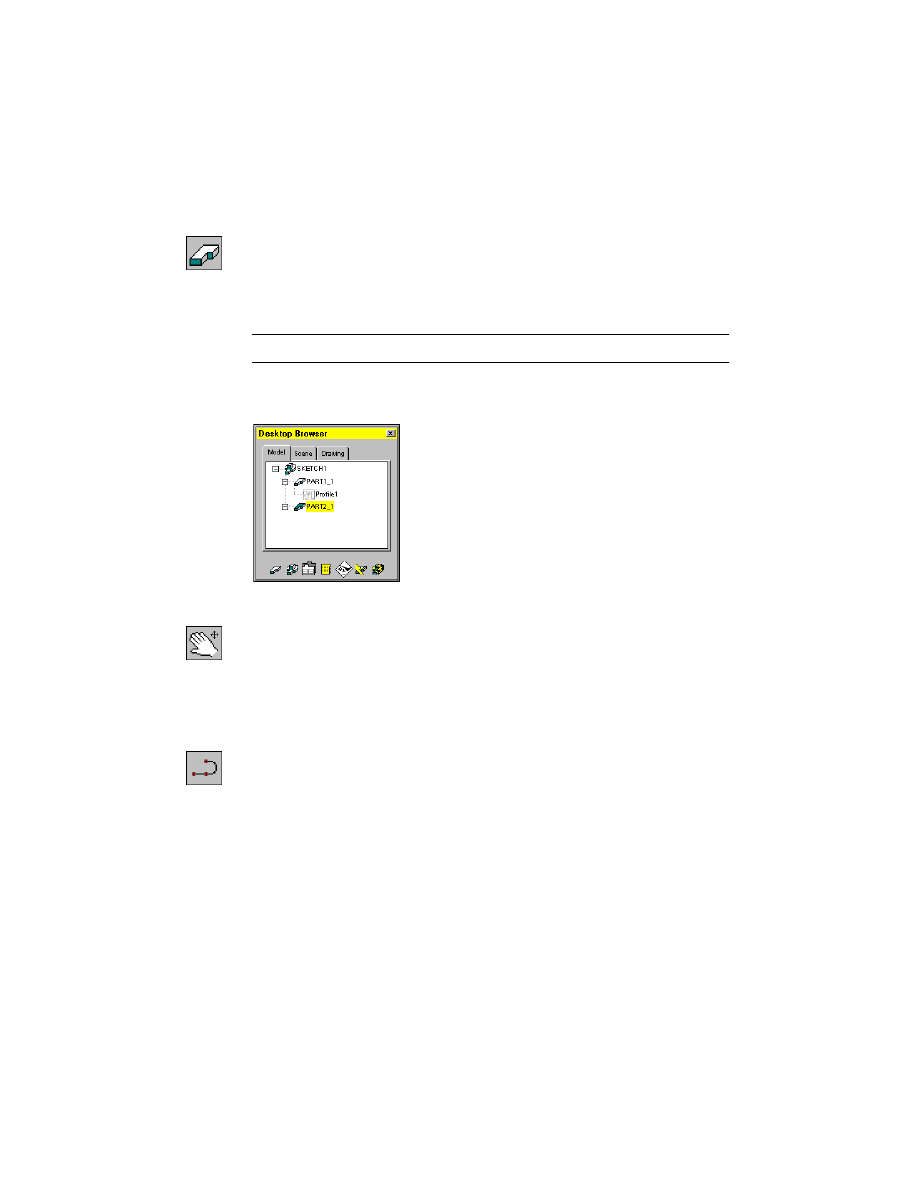
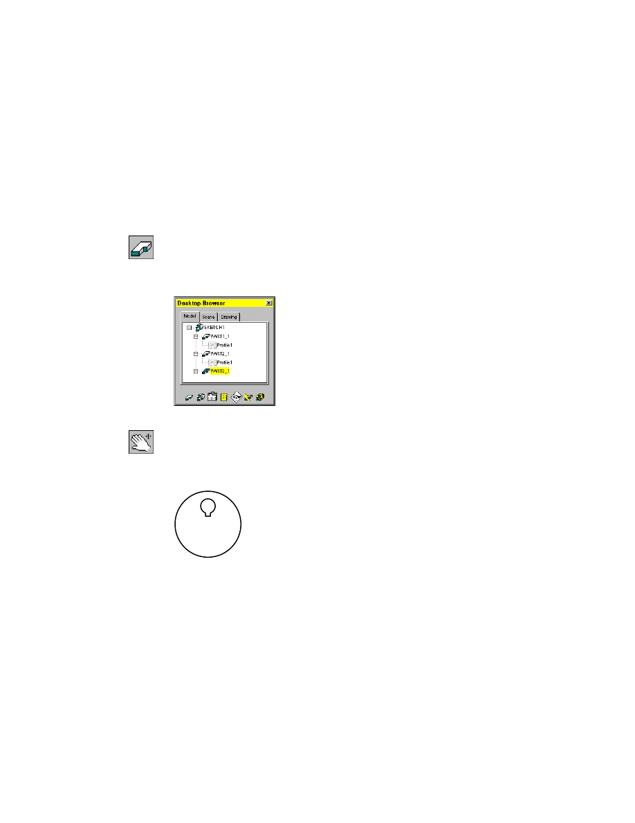
Before you begin, look at the Desktop Browser. It contains an icon with the
drawing file name. There are no other icons in the Browser, which indicates
that your file contains no parts.
You can move the Browser on your desktop and resize it to give yourself more
drawing area. See “Positioning the Desktop Browser” on page 38.
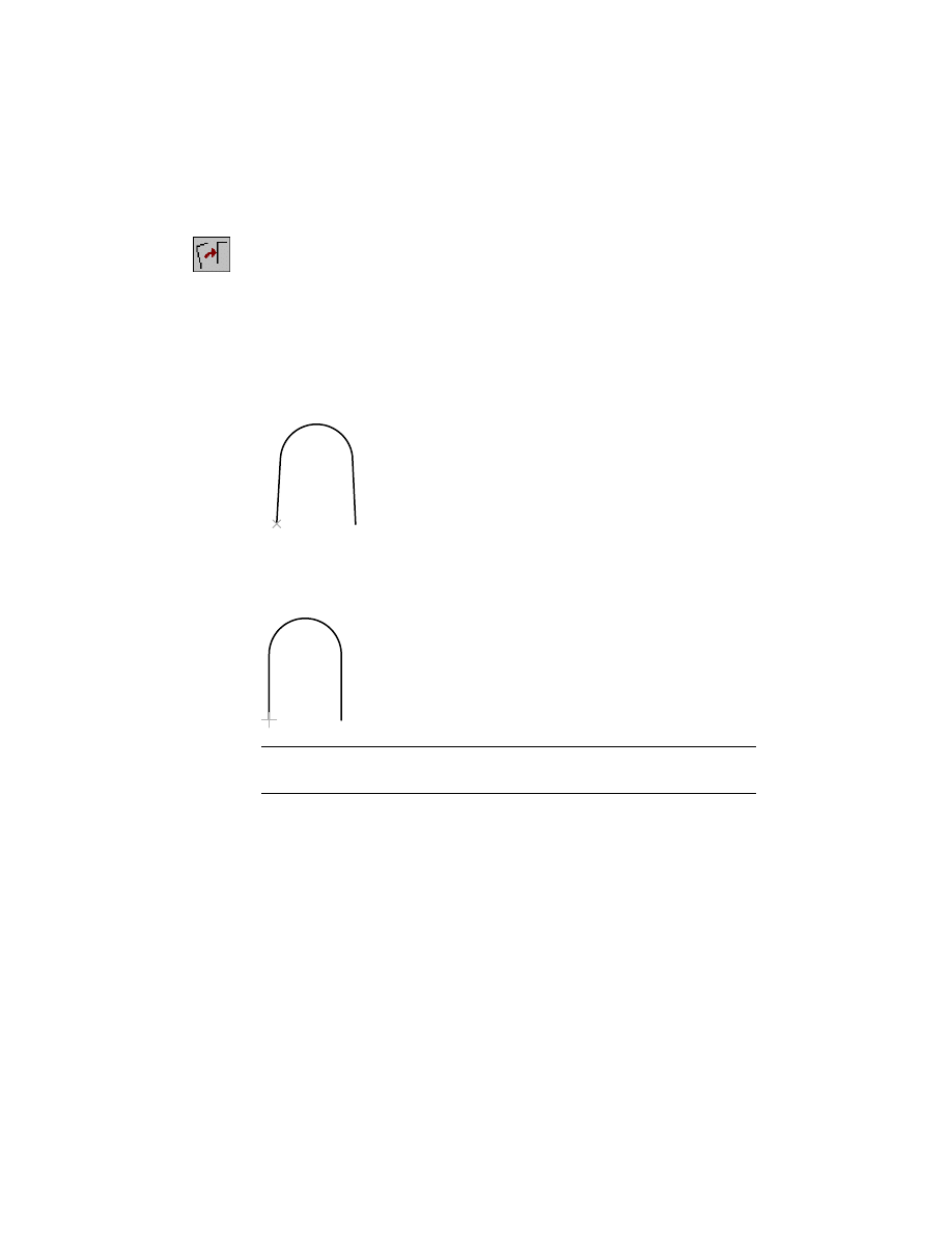
rough sketch
profile sketch
48
|
Chapter 6
Creating Parametric Sketches
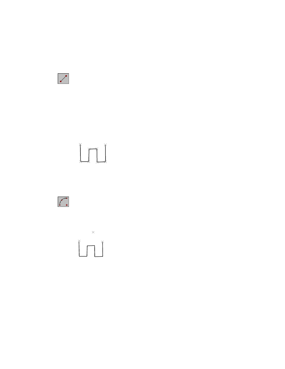
To create a profile sketch from multiple objects
1
Use
LINE
to draw this shape, entering the points in the order shown.
Context Menu
In the graphics area, right-click and choose 2D Sketching
➤ Line.
Specify first point:
Specify a point (1)
Specify next point or [Undo]:
Specify a second point (2)
Specify next point or [Undo]:
Specify a third point (3)
Specify next point or [Close/Undo]:
Specify a fourth point (4)
Specify next point or [Close/Undo]:
Specify a fifth point (5)
Specify next point or [Close/Undo]:
Specify a sixth point (6)
Specify next point or [Close/Undo]:
Specify a seventh point (7)
Specify next point or [Close/Undo]:
Specify an eighth point (8)
Specify next point or [Close/Undo]:
Press
ENTER
You do not need to make the lines absolutely vertical or horizontal. The
objective is to approximate the size and shape of the illustration.
2
Using
ARC
, sketch the top of the shape, following the prompts on the
command line.
Context Menu
In the graphics area, right-click and choose 2D Sketching
➤ Arc.
Specify start point of arc or [CEnter]:
Specify the start point (9)
Specify second point of arc or [CEnter/ENd]:
Specify the second point (10)
Specify end point of arc:
Specify the endpoint (11)
You do not need to use
OSNAP
to connect the arc to the endpoints of the
lines.
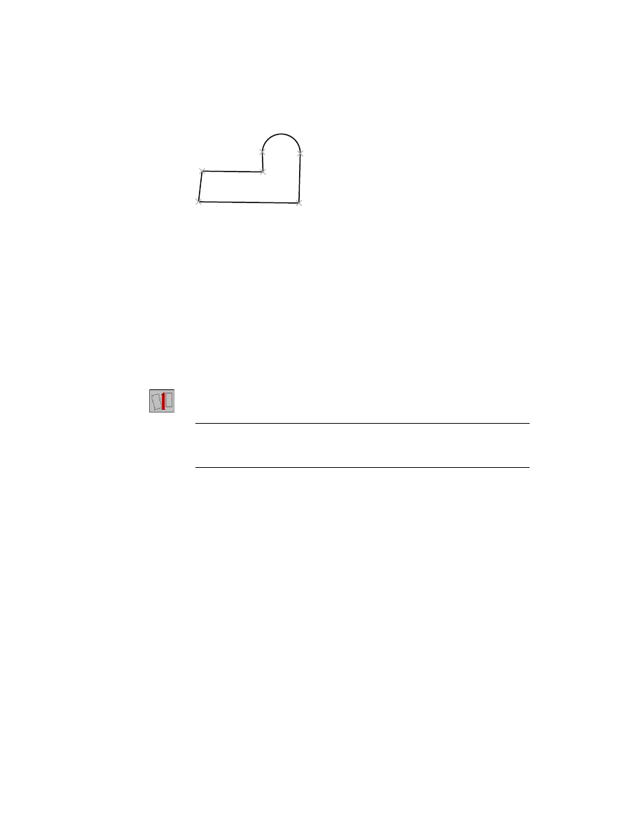
8
7
1
2
3
4
5
6
9
11
10
Creating Profile Sketches
|
49
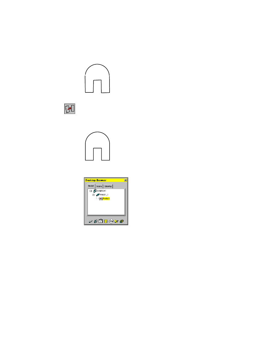
Your sketch should look like this.
3
Create a profile sketch from the rough sketch, responding to the prompts.
Context Menu
In the graphics area, right-click and choose Sketch Solving
➤ Profile.
Select objects for sketch:
Select the arc and the lines
Select objects for sketch:
Press
ENTER
As soon as the sketch is profiled, a part is created. The Browser contains a new
icon labelled PART1_1. A profile icon is nested under the part icon.
According to internal sketching rules, Mechanical Desktop determines
whether to interpret the sketch geometry as rough or precise and whether to
apply constraints.
By default, Mechanical Desktop interprets the sketch as rough and applies
constraints, redrawing the sketch. You can customize these default settings
with Mechanical Options.
50
|
Chapter 6
Creating Parametric Sketches
When redrawing, Mechanical Desktop uses assumed constraints in the
sketch. For example, lines that are nearly vertical are redrawn as vertical, and
lines that are nearly horizontal are redrawn as horizontal.
After the sketch is redrawn, a message on the command line tells you that
Mechanical Desktop needs additional information:
Solved under constrained sketch requiring 5 dimensions or constraints.
Depending on how you drew your sketch, the number of dimensions
required to fully constrain your sketch may differ from that in this exercise.
This message tells you that the sketch is not fully defined. When you add the
missing dimensions or constraints, you determine how the sketch can
change throughout design modifications. Before you add the final con-
straints, you need to show the assumed constraints.
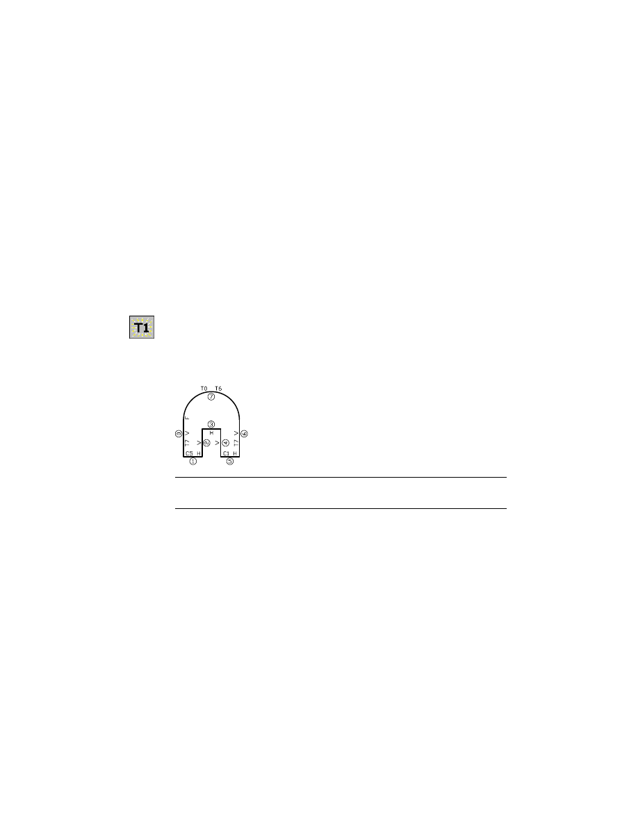
4
Use
AMSHOWCON
to show the existing constraints, following the prompt.
Context Menu
In the graphics area, right-click and choose 2D
Constraints ➤ Show Constraints.
Enter an option [All/Select/Next/eXit] <eXit>:
Enter a
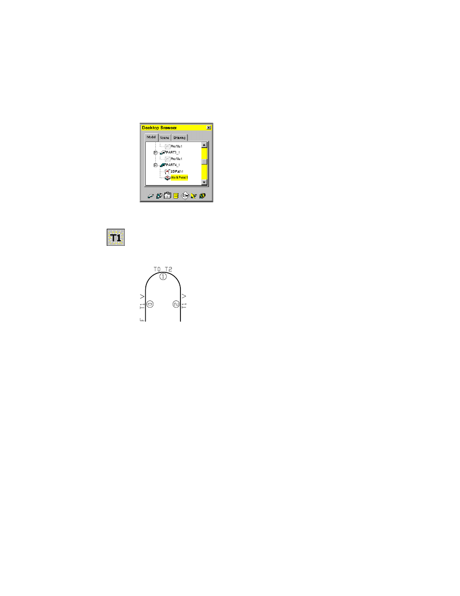
The constraint symbols are displayed.
NOTE
The numbers in your sketch might differ, depending on the order in
which you created the geometric elements.
The sketch has eight geometric elements, seven lines and an arc, each iden-
tified by a number in a circle. Four lines have a V symbol (vertical) and three
lines have an H symbol (horizontal). Two of the horizontal lines have con-
straints denoted by symbols that begin with the letter C (collinear), and three
of the elements have constraints denoted by symbols that begin with the
letter T (tangent).
Creating Profile Sketches
|
51
If your sketch does not contain the same constraints, redraw it to more
closely resemble the illustrations in steps 1 and 2.
Notice the letter F, located at the start point of line 0. It indicates that a fix
constraint has been applied to that point. When Mechanical Desktop solves
a sketch, it applies a fix constraint to the start point of the first segment of
your sketch. This point serves as an anchor for the sketch as you make
changes. It remains fixed in space, while other points and geometry move
relative to it.
You may delete this constraint if you wish, and apply one or more fix con-
straints to the endpoints of sketch segments, or to the segments themselves,
in order to make your sketch more rigid.
5
To hide the constraints, respond to the prompt as follows:
Enter an option [All/Select/Next/eXit] <eXit>:
Press
ENTER
Save your file.
You have successfully created a profile sketch. In chapter 7, “Constraining
Sketches,” you learn to create, modify, and delete constraints and parametric
dimensions.
Using Custom Sketch Rules
Custom settings affect how Mechanical Desktop analyzes rough sketches. In
this exercise, you sketch with
PLINE
and convert your drawing to a profile
sketch. You will modify one of the Mechanical Options sketch rule settings
and see its effect on the sketch.
Before you begin the next exercise, create a new part definition.
rough sketch
profile sketch
52
|
Chapter 6
Creating Parametric Sketches
To create a new part definition
1
Use the context menu to initiate a new part definition.
Context Menu
In the graphics area, right-click and choose Part ➤ New
Part.
2
Respond to the prompts as follows:
Select an object or enter new part name <PART2>:
Press
ENTER
NOTE
The command method you use determines which prompts appear.
A new part definition is created in the drawing and displayed in the Browser.
The new part automatically becomes the active part.
3
Pan the drawing so you have room to create the next sketch.
Context Menu
In the graphics area, right-click and choose Pan.
You are ready for the next exercise.
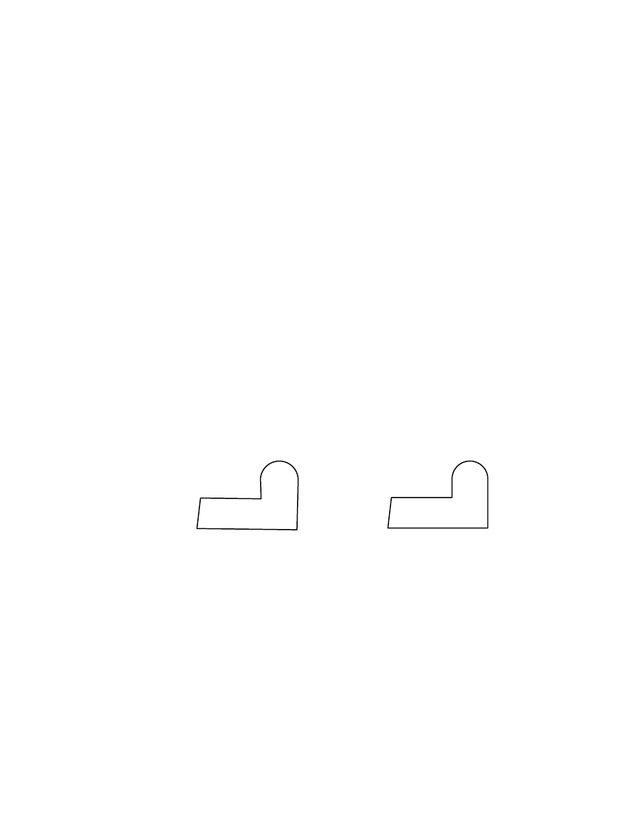
To create a profile sketch from a single polyline
1
Use
PLINE
to draw this rough sketch as a continuous shape, following the
prompts for the first four points.
Context Menu
In the graphics area, right-click and choose 2D Sketching
➤ Polyline.
Specify start point:
Specify a point (1)
Current line-width is 0.0000
Specify next point or [Arc/Close/Halfwidth/Length/Undo/Width]:
Specify a second point (2)
Specify next point or [Arc/Close/Halfwidth/Length/Undo/Width]:
Specify a third point (3)
Specify next point or [Arc/Close/Halfwidth/Length/Undo/Width]:
Specify a fourth point (4)
Creating Profile Sketches
|
53
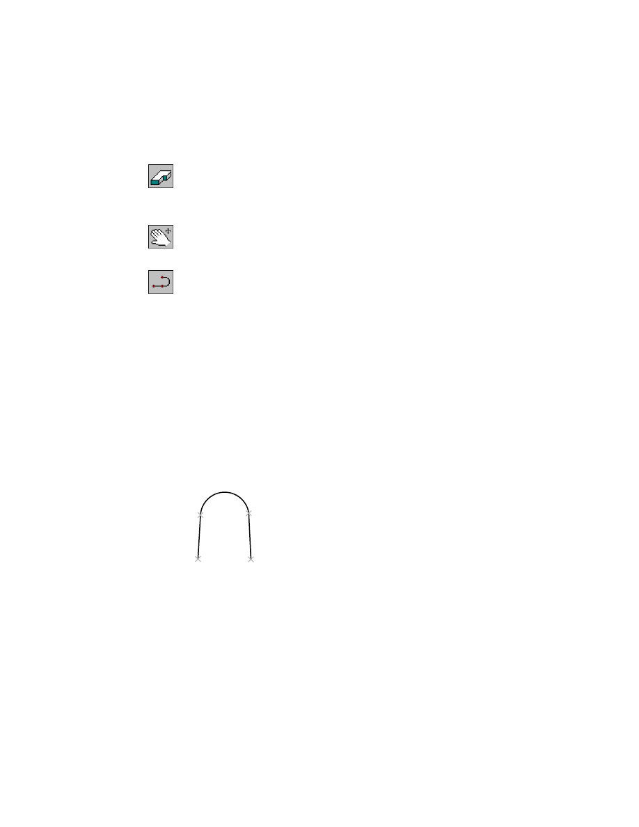
2
Following the prompts, switch to Arc to create the arc segment, then switch
back to Line. Switch to Close to finish the sketch.
Specify next point or [Arc/Close/Halfwidth/Length/Undo/Width]:
Enter a
Specify endpoint of arc or
[Angle/CEnter/CLose/Direction/Halfwidth/Line/Radius/Second pt/Undo/Width]:
Specify a fifth point (5)
Specify endpoint of arc or
[Angle/CEnter/CLose/Direction/Halfwidth/Line/Radius/Second pt/Undo/Width]:
Enter l
Specify next point or [Arc/Close/Halfwidth/Length/Undo/Width]:
Specify a sixth point (6)
Specify next point or [Arc/Close/Halfwidth/Length/Undo/Width]:
Enter c
3
Use
AMPROFILE
to create a profile sketch from the rough sketch.
Context Menu
In the graphics area, right-click and choose Sketch Solving
➤ Single Profile.
NOTE
If you used line segments and an arc to draw your sketch you cannot
use Single Profile. This command profiles single object sketches only. For
sketches containing more than one object, use Profile.
When you use Single Profile, you are not prompted to select the sketch geom-
etry. Mechanical Desktop looks for the last entity you created. If it is a valid
closed loop, Mechanical Desktop analyzes the sketch, redraws it, and displays
the following message:
Solved under constrained sketch requiring 5 dimensions or constraints.
1
4
3
5
6
2
54
|
Chapter 6
Creating Parametric Sketches
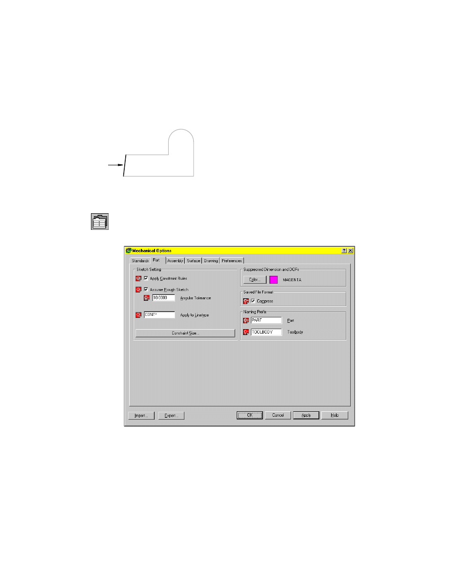
All lines were redrawn as horizontal or vertical except one. L1 remains angled
because the angle of the line exceeds the setting for angular tolerance. By
default, this rule makes a line horizontal or vertical if the angle is within 4
degrees of horizontal or vertical.
You can modify this and other sketch tolerance settings to adjust the preci-
sion of your sketch analysis.
4
Change the angular tolerance setting.
Browser
Click the Options button below the window.
5
In the Mechanical Options dialog box, choose the Part tab and change the
angular tolerance from 4 degrees to 10 degrees, the maximum value.
Choose OK.
L1
Creating Profile Sketches
|
55
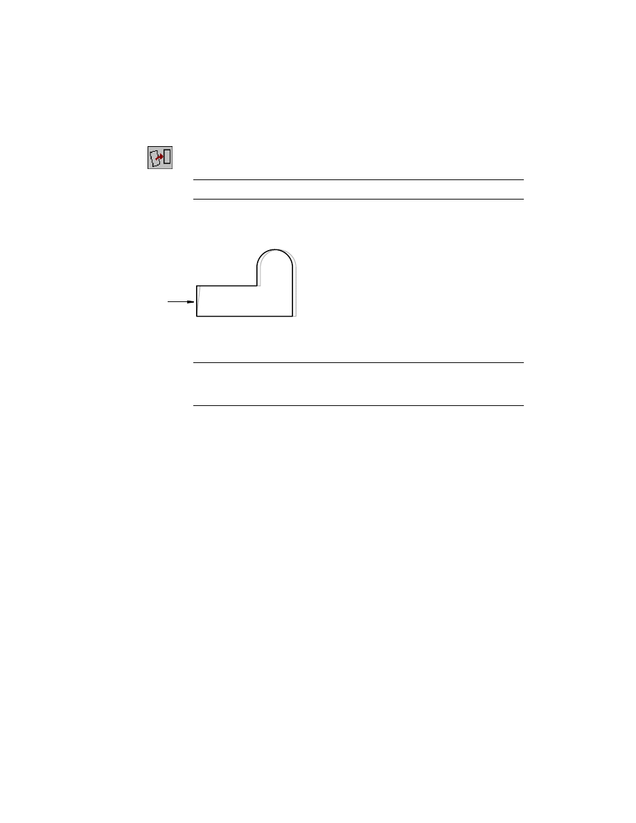
6
Reprofile the sketch, responding to the prompts.
Context Menu
In the graphics area, right-click and choose Sketch Solving
➤ Profile.
NOTE
You cannot use Single Profile to reprofile a sketch.
Select objects for sketch:
Use a crossing window to specify the sketch
Select objects for sketch:
Press
ENTER
If your sketch shows line L1 unchanged, the angle was greater than 10
degrees. You need to edit or redraw the shape and append the sketch.
NOTE
When adding geometry or changing a sketch, you must append the
new geometry so that the sketch is reanalyzed and constraints are reapplied. See
chapter 7, “Constraining Sketches,” to append geometry to a sketch.
When L1 was made vertical, it required one less dimension or constraint to
fully solve the sketch. The following message is displayed on the command
line.
Solved underconstrained sketch requiring 4 dimensions or constraints.
Save your file.
You can adjust sketch rules that determine how precisely you need to draw.
For most sketching, you should use the default settings. However, you can
change the default settings as needed.
L1
56
|
Chapter 6
Creating Parametric Sketches
Using Nested Loops
You can select more than one closed loop to create a profile sketch. A closed
loop must encompass the nested loops. They cannot overlap, intersect, or
touch. With nested loops you can easily create complex profile sketches.
To create a profile sketch using nested loops
1
Use
AMNEW
to create a new part definition.
Context Menu
In the graphics area, right-click and choose Part ➤ New
Part.
2
Accept the default part name on the command line.
The Browser now contains a third part.
3
Pan the drawing so you have room to create the next sketch.
Context Menu
In the graphics area, right-click and choose Pan.
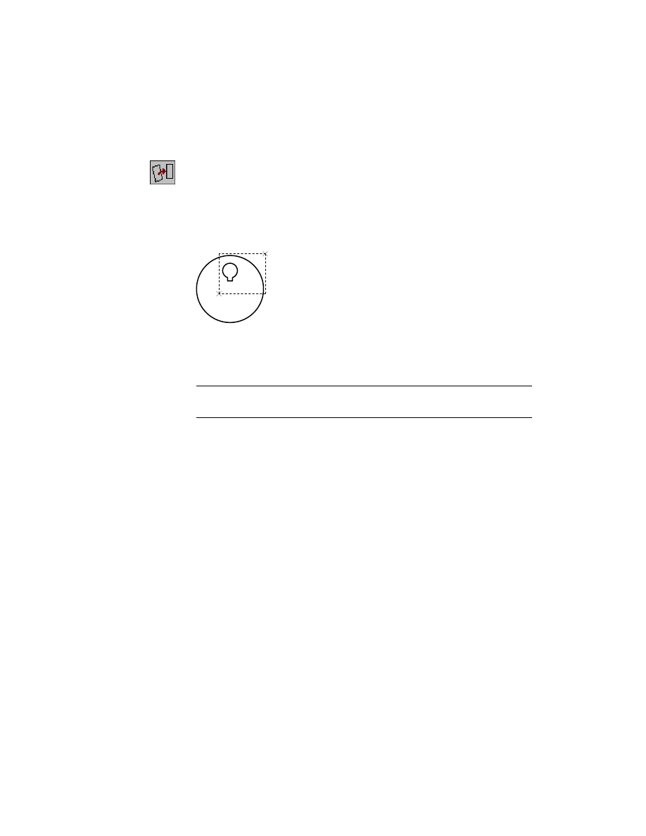
4
Create the following sketch using lines or polylines, and circles. Then, in the
graphics area, right-click and choose 2D Sketching ➤ Trim and follow the
prompts on the command line to remove the section from the smaller circle.
Creating Profile Sketches
|
57
5
Profile the sketch, following the prompts to select the objects with a crossing
window.
Context Menu
In the graphics area, right-click and choose Sketch Solving
➤ Profile.
Select objects for sketch:
Specify a point to the right of the sketch (1)
Specify opposite corner:
Specify a second point (2)
5 found
Select objects for sketch:
Press
ENTER
Mechanical Desktop calculates the number of dimensions or constraints
required to fully constrain the profile.
Solved underconstrained sketch requiring 7 dimensions or constraints.
NOTE
You may need more dimensions or constraints, depending on how you
created your sketch.
Save your file.
This simple cam illustrates how you can easily create complex shapes to
define parts and features. Experiment on your own to create profiles from
nested loops.
1
2
58
|
Chapter 6
Creating Parametric Sketches
Creating Path Sketches
Path sketches can be both two dimensional and three dimensional. Like
open profile sketches, they can be open shapes. In this exercise, you create
only the path sketches, but not the profiles that would sweep along the
paths.
Creating 2D Path Sketches
A 2D path sketch serves as a trajectory for a swept feature. You create a swept
feature by defining a path and then a profile sketch of a cross section. Then,
you sweep the profile along the path.
The geometry for the 2D path must be created on the same plane.
Valid geometry that can be used to create a 2D path includes
■
Lines
■
Arcs
■
Polylines
■
Ellipse segments
■
2D splines
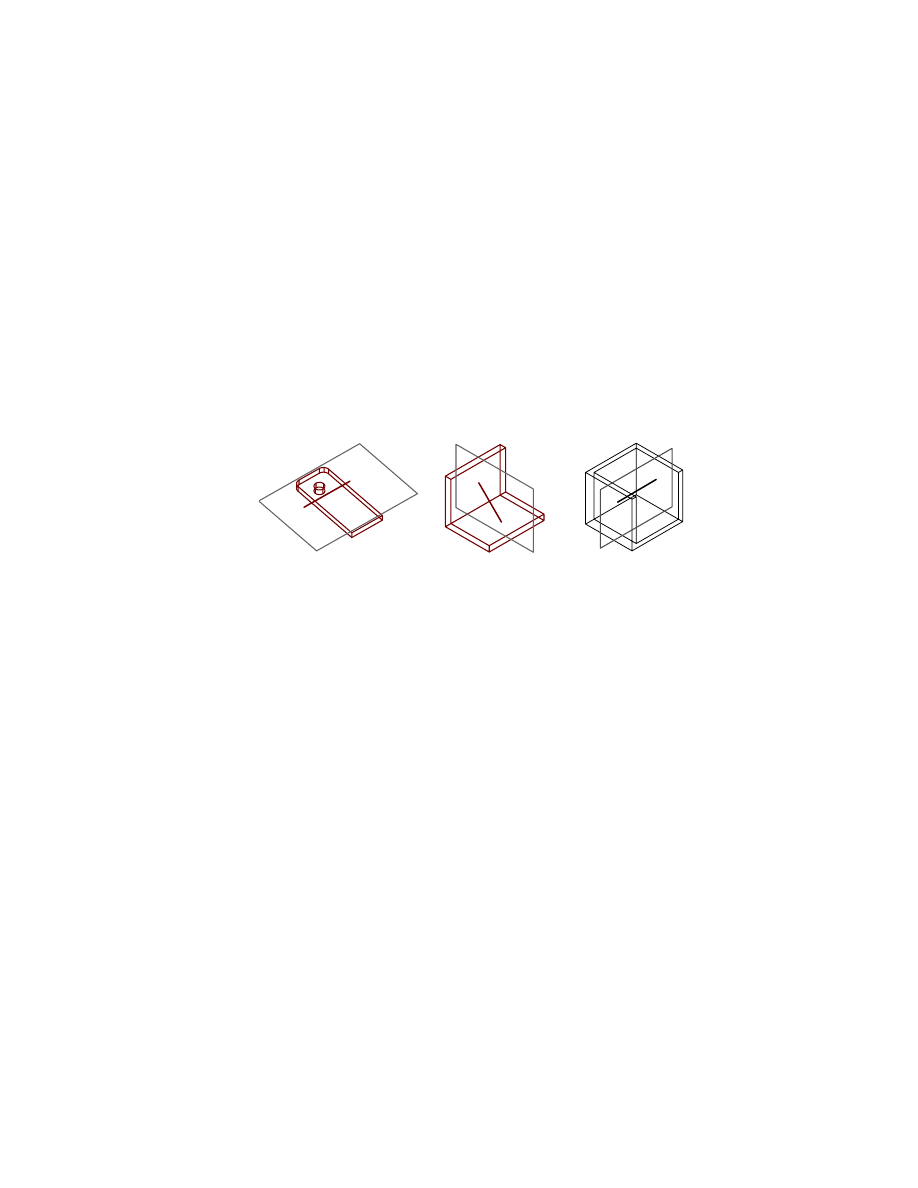
When you solve a 2D path sketch, you can automatically create a work plane
normal to the start point of the path. You use this work plane to create a pro-
file sketch for the swept feature, and then constrain the profile sketch to the
start point of the path.
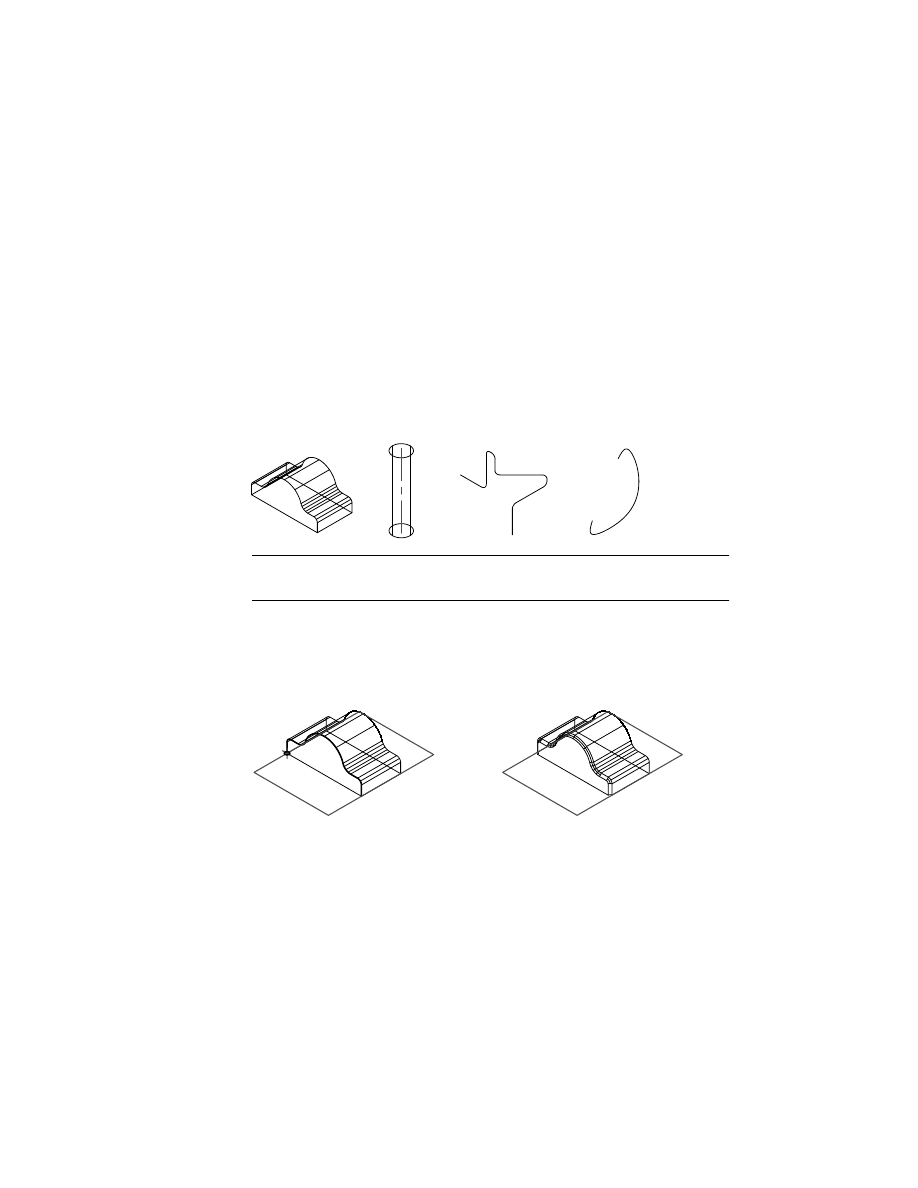
swept feature
path sketch
profile sketch
Creating Path Sketches
|
59
To create a 2D path sketch
1
Create a new part definition.
Context Menu
In the graphics area, right-click and choose Part ➤ New
Part.
2
Press
ENTER
on the command line to accept the default part name.
3
Pan the drawing so you have room to create the next sketch.
Context Menu
In the graphics area, right-click and choose Pan.
4
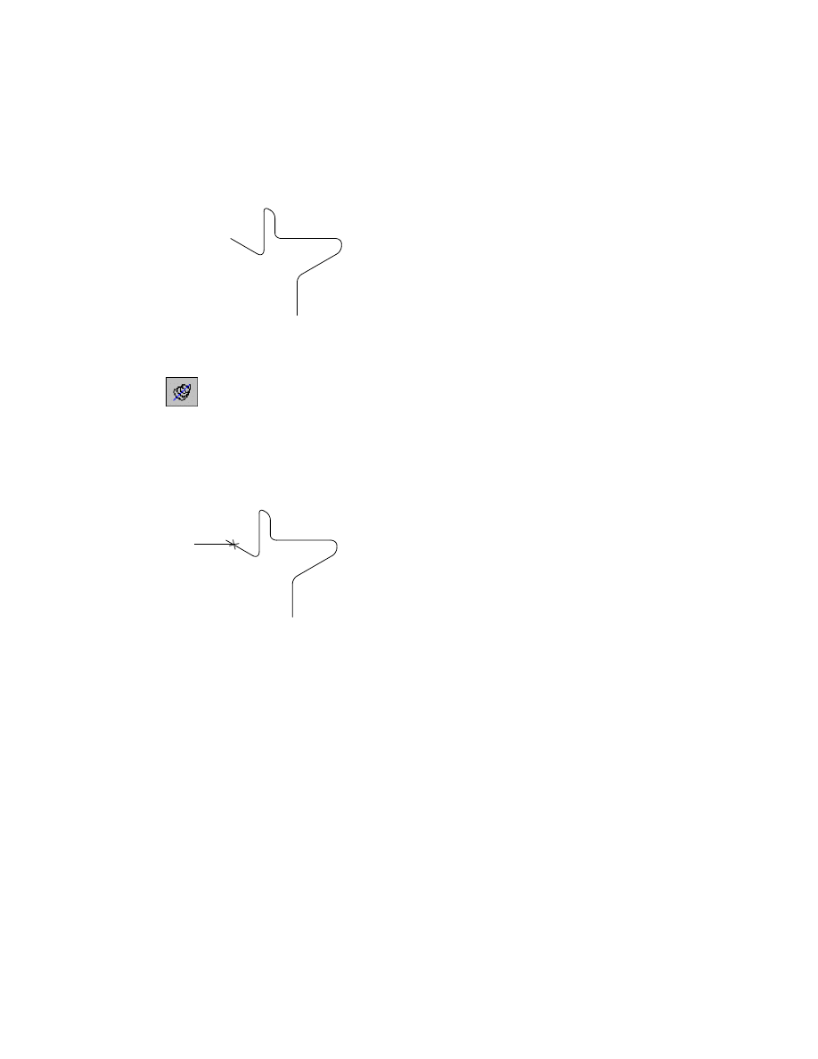
Use
PLINE
to draw the rough sketch as a continuous shape, responding to the
prompts to specify the points in the following illustration.
Context Menu
In the graphics area, right-click and choose 2D Sketching
➤ Polyline.
Specify start point:
Specify a point (1)
Current line-width is 0.0000
Specify next point or [Arc/Close/Halfwidth/Length/Undo/Width]:
Specify a second point (2)
Specify next point or [Arc/Close/Halfwidth/Length/Undo/Width]:
Enter a to create an arc segment
Specify endpoint of arc or
[Angle/CEnter/CLose/Direction/Halfwidth/Line/Radius/Second pt/Undo/Width]:
Specify a third point (3)
Specify endpoint of arc or
[Angle/CEnter/CLose/Direction/Halfwidth/Line/Radius/Second pt/Undo/Width]:
Enter l to create a line segment
Specify next point or [Arc/Close/Halfwidth/Length/Undo/Width]:
Specify a fourth point (4)
Specify next point or [Arc/Close/Halfwidth/Length/Undo/Width]:
Press
ENTER
Make sure to switch between drawing lines and arcs at points (2) and (3).
1
2
3
4
60
|
Chapter 6
Creating Parametric Sketches
5
Use
AM2DPATH
to convert the rough sketch to a path sketch, following the
prompts.
Context Menu
In the graphics area, right-click and choose Sketch Solving
➤ 2D Path.
Select objects:
Specify the polyline shape
Select objects:
Press
ENTER
At the prompt for the start point of the path, you select the point where the
path begins. This determines the direction to sweep the profile of the cross
section.
Select start point of the path:
Specify the start point (1)
You can also specify whether a work plane is created perpendicular to the
path. In this example, a work plane is not required.
Create a profile plane perpendicular to the path? [Yes/No] <Yes>:
Enter n
NOTE
If you choose to create a sketch to sweep along the path, Mechanical
Desktop can automatically place a work plane perpendicular to the path.
Press the F2 function key to activate the AutoCAD Text window. Examine the
prompts for the AM2DPATH command. The following line is displayed:
Solved underconstrained sketch requiring 3 dimensions or constraints.
The sketch analysis rules indicate that the path sketch needs three more
dimensions or constraints to fully define the sketch.
1
Creating Path Sketches
|
61
A work point is automatically placed at the start point of the path. The
Browser displays both a 2DPath icon and a work point icon nested below the
part definition.
6
Use
AMSHOWCON
to display the existing constraints, responding to the
prompt.
Context Menu
In the graphics area, right-click and choose 2D
Constraints ➤ Show Constraints.
Enter an option [All/Select/Next/eXit] <eXit>:
Enter a
The start point of the path is fixed. Both lines are vertical and are tangent to
the endpoints of the arc. The missing information is the length of each line and
the radius of the arc. Given these values, the sketch would be fully constrained.
Enter an option [All/Select/Next/eXit] <eXit>:
Press
ENTER
Save your file.
Next, you create a three-dimensional path.
62
|
Chapter 6
Creating Parametric Sketches
Creating 3D Path Sketches
3D path sketches are used to create
■
A 3D path from existing part edges
■
A helical path
■
The centerline of a 3D pipe
■
A 3D spline path
3D paths are used to create swept features that are not limited to one plane.
See chapter 8, “Creating Sketched Features,” to learn more about sweeping
features along a 3D path.
Open the file sketch2.dwg in the desktop\tutorial folder. The drawing contains
four part definitions and the geometry you need to create the 3D paths.
NOTE
Back up the tutorial drawing files so you still have the original files if you
make a mistake. See “Backing up Tutorial Drawing Files” on page 40.
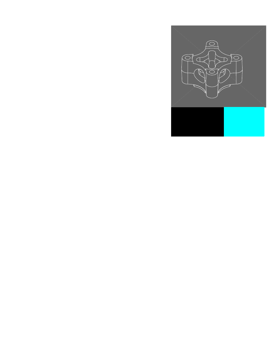
Creating a 3D Edge Path
A 3D edge path is used to create a path from existing part edges. After you
create the path, you can sweep a profile and use a Boolean operation to com-
bine the feature with the existing part.
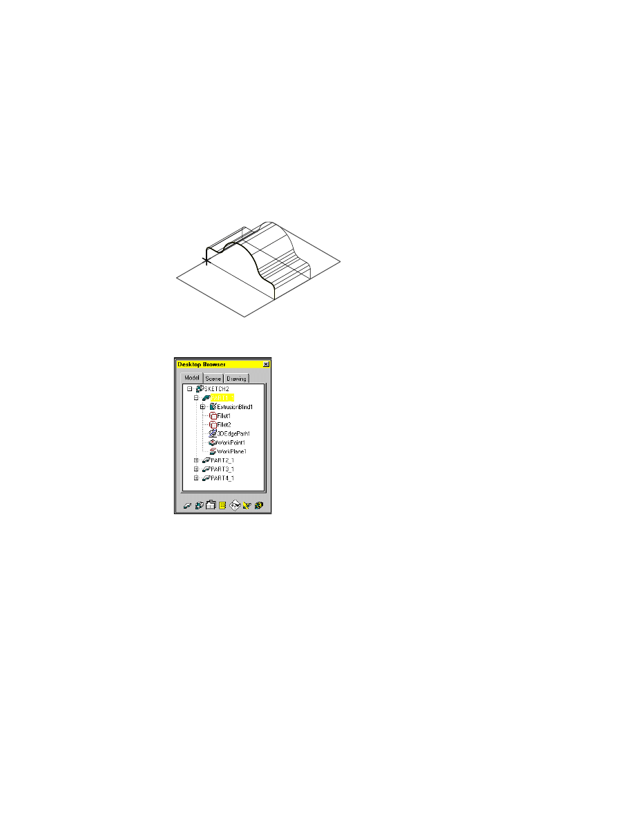
3D edge path and profile sketch
3D sweep along edge path
Creating Path Sketches
|
63
Before you can work on a part, it must be active. Activate PART1_1, respond-
ing to the prompts.
Context Menu
In the graphics area, right-click and choose Part ➤
Activate Part.
Select part to activate or [?] <PART1_1>:
Enter
PART1_1
PART1_1 is activated, and highlighted in the Browser.
Use Pan to center PART1_1 on your screen.
Context Menu
In the graphics area, right-click and choose Pan.
PART1_1 contains an extruded part.
To create a 3D edge path
1
Use
AM3DPATH
to define the 3D edge path, following the prompts.
Context Menu
In the graphics area, right-click and choose Sketch Solving
➤ 3D Edge Path.
Select model edges (to add):
Specify the first part edge (1)
Select model edges (to add):
Specify the next edges in a clockwise sequence
Select model edges (to add):
Specify the last edge (9)
Select model edges (to add):
Press
ENTER
Specify start point:
Specify start point (1)
Create workplane? [Yes/No] <Yes>:
Press
ENTER
The command method you use determines the prompts that are displayed.
9
1
64
|
Chapter 6
Creating Parametric Sketches
2
Continue on the command line to place the work plane.
Plane=Parametric
Select edge to align X axis or [Flip/Rotate/Origin] <accept>:
Press
ENTER
The path is created, and a work point is located at the start point. A work
plane is placed normal to the start of the path so you can sketch the profile
for the sweep feature.
In the Browser, the new geometry is nested below the extrusion and fillets in
PART1_1.
Save your file.
Creating Path Sketches
|
65
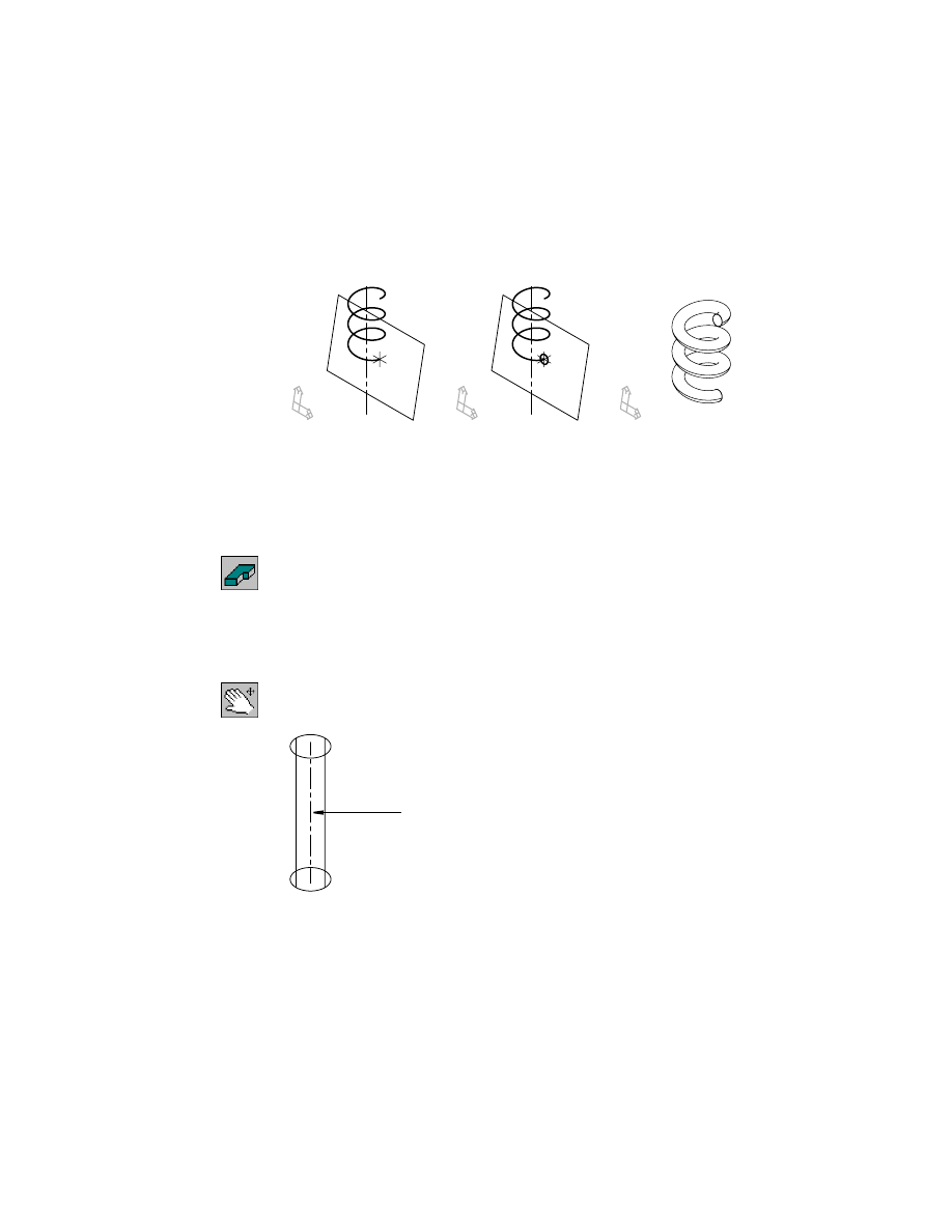
Creating a 3D Helical Path
A 3D helical path is used for a special type of swept feature. Helical sweeps
are used to create threads, springs, and coils. You create a 3D helical path
from an existing work axis, cylindrical face, or cylindrical edge.
When you create a 3D helical path, you can specify whether a work plane is
also created. The work plane can be normal to the path, at the center of the
path, or along the work axis. You use this work plane to draw the profile
sketch for the helical sweep.
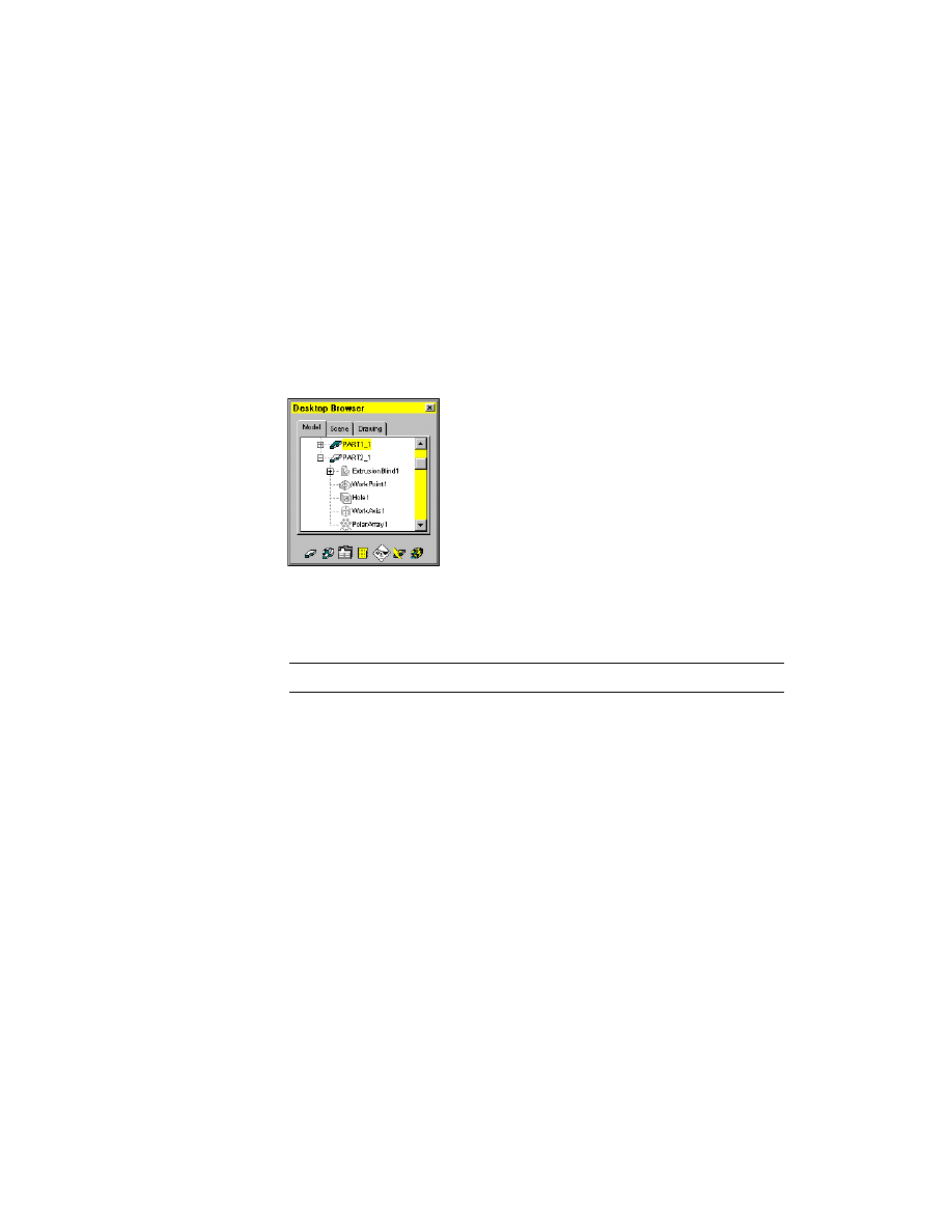
Before you begin, activate PART2_1, responding to the prompts.
Context Menu
In the graphics area, right-click and choose Part ➤
Activate Part.
Select part to activate or [?] <PART1_1>:
Enter
PART2_1
PART2_1 is highlighted in the Browser and on your screen.
Use Pan to center PART2_1 on your screen.
Context Menu
In the graphics area, right-click and choose Pan.
PART2_1 contains a cylinder and a work axis.
3D path
profile sketch
3D helical sweep
work axis
66
|
Chapter 6
Creating Parametric Sketches
To create a 3D helical path
3
Use
AM3DPATH
to define the 3D helical path, responding to the prompts.
Context Menu
In the graphics area, right-click and choose Sketch Solving
➤ 3D Helix Path.
Enter path type [Helical/Spline/Edge/Pipe] <Edge>:
Enter h
Select work axis, circular edge, or circular face for helical center:
Select the work axis (1)
The command method you use determines the prompts that are displayed.
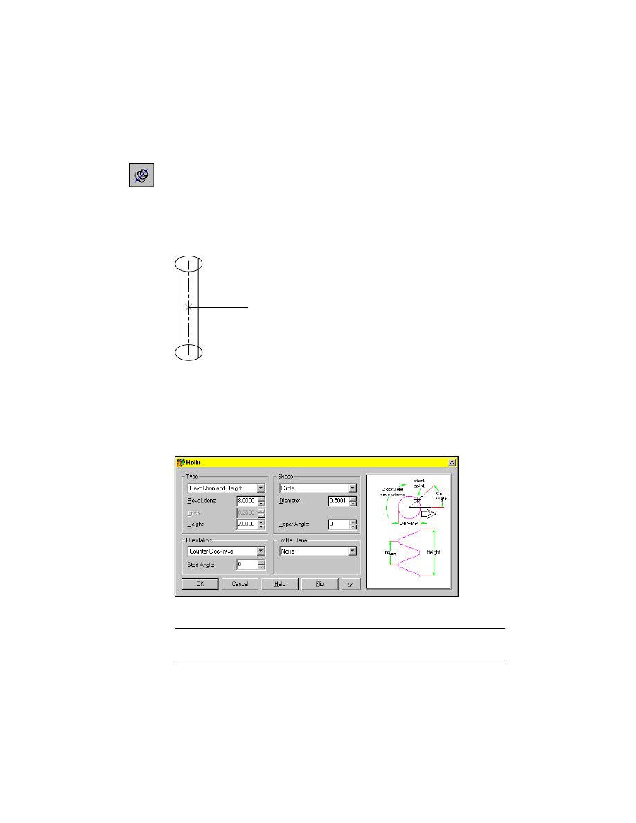
4
In the Helix dialog box, specify the following:
Type:
Revolution and Height
Revolutions:
Enter 8
Height:
Enter 2
Diameter:
Enter .5
Orientation:
Counter-Clockwise
Choose OK.
NOTE
The path is automatically constrained with the parameters defined in
the Helix dialog box. You can edit the path at any time with
AMEDITFEAT
.
1
Creating Path Sketches
|
67
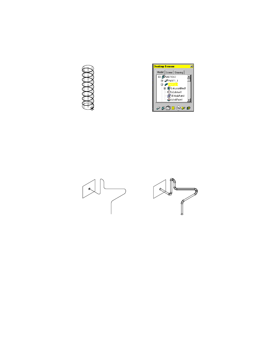
The 3D helix path is created. A work point is placed at the beginning of the path.
You can also specify that a work plane is placed normal to the start point of
the 3D path, at the center of the path, or along the work axis. This option
makes it easier for you to create the sketch geometry for the profile you sweep
along the path.
Save your file.
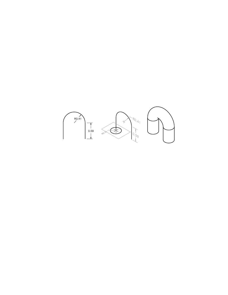
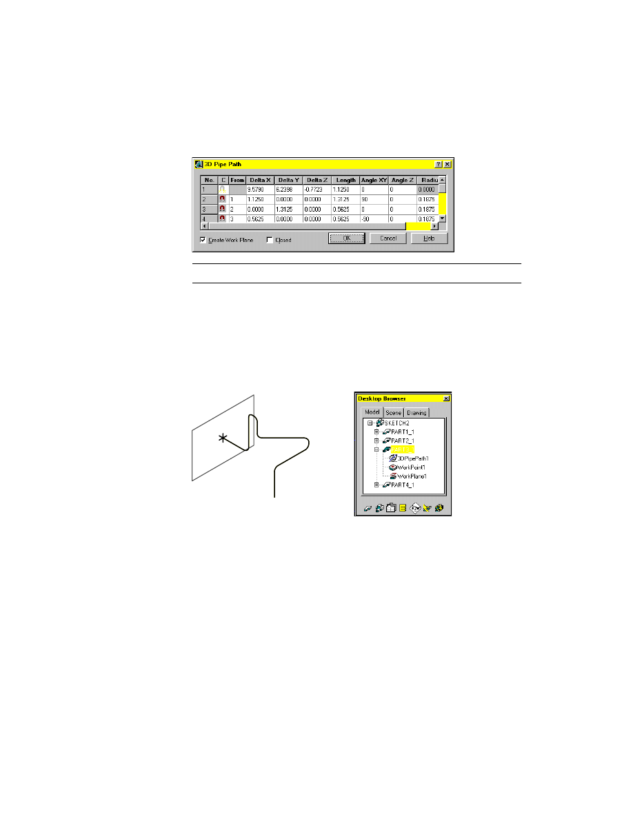
Creating a 3D Pipe Path
A 3D pipe path is used to sweep a feature along a three-dimensional path
containing line and arc segments or filleted polylines. You can modify each
of the control points and the angle of the segments in the 3D Pipe Path
dialog box.
Before you begin, activate PART3_1. This time use the Browser method to
activate the part.
Browser
In the graphics area, double-click PART3_1.
PART3_1 is activated, and highlighted in the Browser.
3D pipe path and profile sketch
3D sweep along pipe path
68
|
Chapter 6
Creating Parametric Sketches
Use Pan to center PART3_1 on your screen.
PART3_1 contains an unsolved sketch of line segments and arcs.
To create a 3D pipe path
1
Use
AM3DPATH
to define the 3D pipe path, responding to the prompts.
Context Menu
In the graphics area, right-click and choose Sketch Solving
➤ 3D Pipe Path.
Select polyline path source:
Select the first line (1)
Select polyline path source:
Select the remaining arcs and lines in sequence
Select polyline path source:
Press
ENTER
Specify start point:
Specify a point near the start of the first line (1)
The command method you use determines the prompts that are displayed.
1
Creating Path Sketches
|
69
2
In the 3D Pipe Path dialog box, examine the vertices and angles of the path.
Verify that Create Work Plane is selected.
NOTE
Your numbers might not match the illustration above.
Choose OK to exit the dialog box.
3
Place the work plane, following the prompts.
Plane=Parametric
Select edge to align X axis or [Flip/Rotate/Origin] <accept>:
Press
ENTER
The Desktop Browser now contains a 3D Pipe icon, a work plane, and a work
point nested below the PART3_1 definition.
Save your file.
70
|
Chapter 6
Creating Parametric Sketches
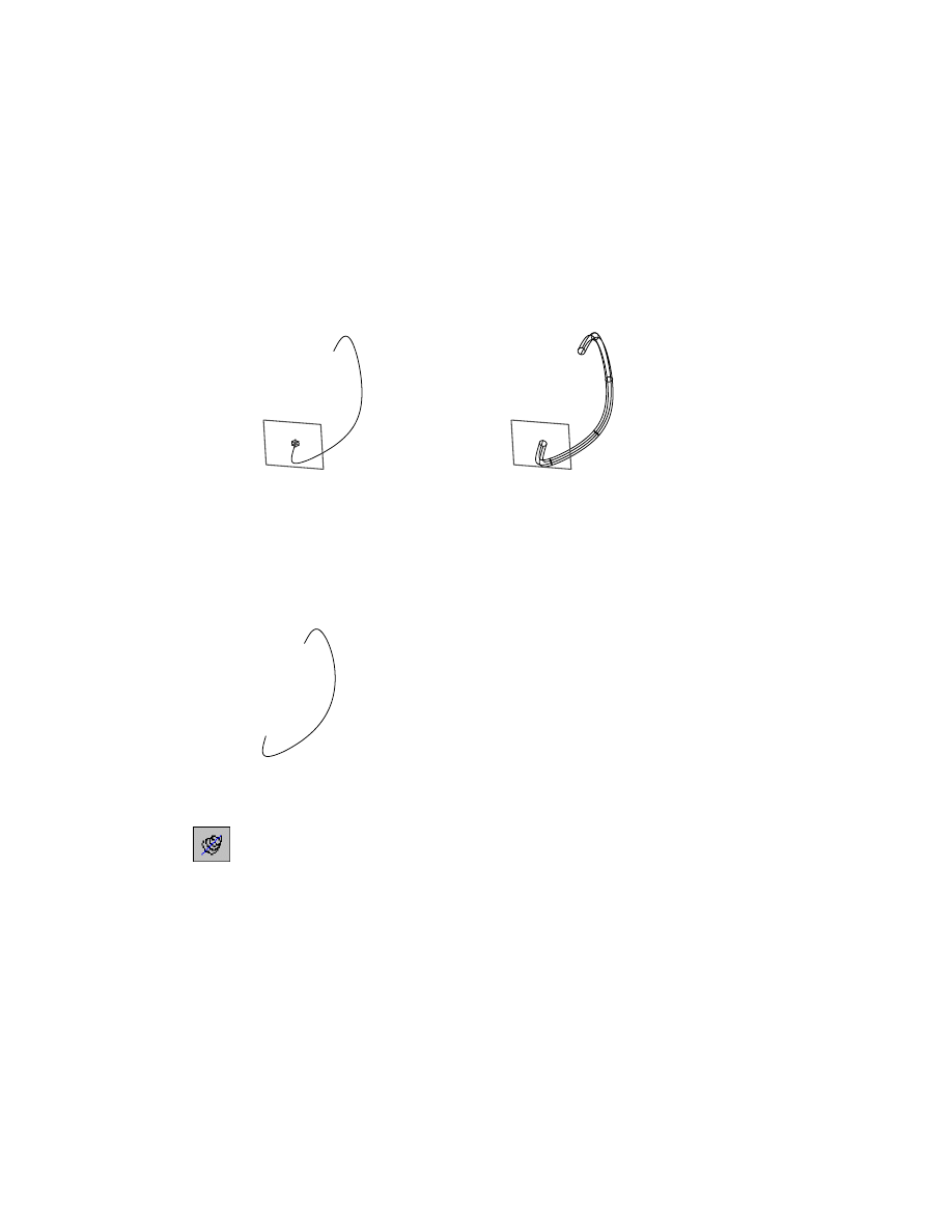
Creating a 3D Spline Path
In this type of path, you sweep a feature along a 3D spline created with fit
points or control points. Working in one integrated dialog box, you can mod-
ify any fit point or control point in a 3D spline path, and you can convert fit
points to control points, and control points to fit points.
In this exercise, you work with a fit point spline.
Before you begin, activate PART4_1 from the Browser.
Browser
In the graphics area, double-click PART4_1.
PART4_1 is highlighted in the Browser and on your screen.
Use Pan to center PART4_1 on your screen.
PART4_1 contains an unsolved spline sketch.
To create a 3D spline path
1
Use
AM3DPATH
to define the 3D spline path, responding to the prompts.
Context Menu
In the graphics area, right-click and choose Sketch Solving
➤ 3D Spline Path.
Select 3D spline path source:
Specify the spline
Specify start point:
Specify the start point
The command method you use determines the prompts that are displayed.
3D spline path and profile sketch
3D sweep along spline path

Creating Path Sketches
|
71
2
In the 3D Spline Path dialog box, examine the vertices of the spline, and ver-
ify that Create Work Plane is selected.
NOTE
Your numbers might not match the illustration above.
Choose OK to exit the dialog box.
3
Create the work plane, responding to the prompts.
Plane=Parametric
Select edge to align X axis or [Flip/Rotate/Origin] <accept>:
Press
ENTER
The path is created, and a work point is located at the start point. A work
plane is placed normal to the start of the path so you can begin to sketch the
profile for the sweep feature.
Save your file.
Creating a path sketch is similar to creating a profile sketch. The difference
between the two sketch types is their purpose.
■
Profile sketches provide a general way to create a variety of features.
■
Path sketches are used exclusively for creating trajectory paths for 2D and
3D swept features.
72
|
Chapter 6
Creating Parametric Sketches
Creating Cut Line Sketches
When you create drawing views, you might want to depict a cut path across
a part for offset, cross-section views. After you have extruded or revolved a
profile sketch to create a feature, you can return to an original sketch and
draw the cut line across the features you want to include in the cross section.
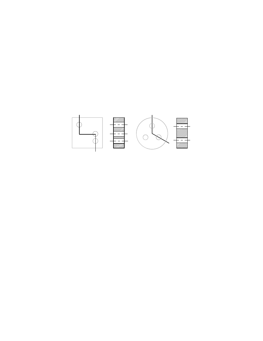
There are two types of cut line sketches: offset and aligned. An offset cut line
sketch is a two-dimensional line constructed from orthogonal segments. An
aligned cut line sketch is a two-dimensional line constructed from non-
orthogonal segments.
Two general rules govern cut line sketches:
■
Only line and polyline segments are allowed.
■
The start and end points of the cut line must be outside the part.
These additional rules apply to cut line sketches:
■
The first and last line segments of an offset cut line must be parallel.
■
Offset cut line segments can change direction in 90-degree increments
only.
■
Only two line segments are allowed in an aligned cut line.
■
Line segments of aligned cut lines can change direction at any angle.
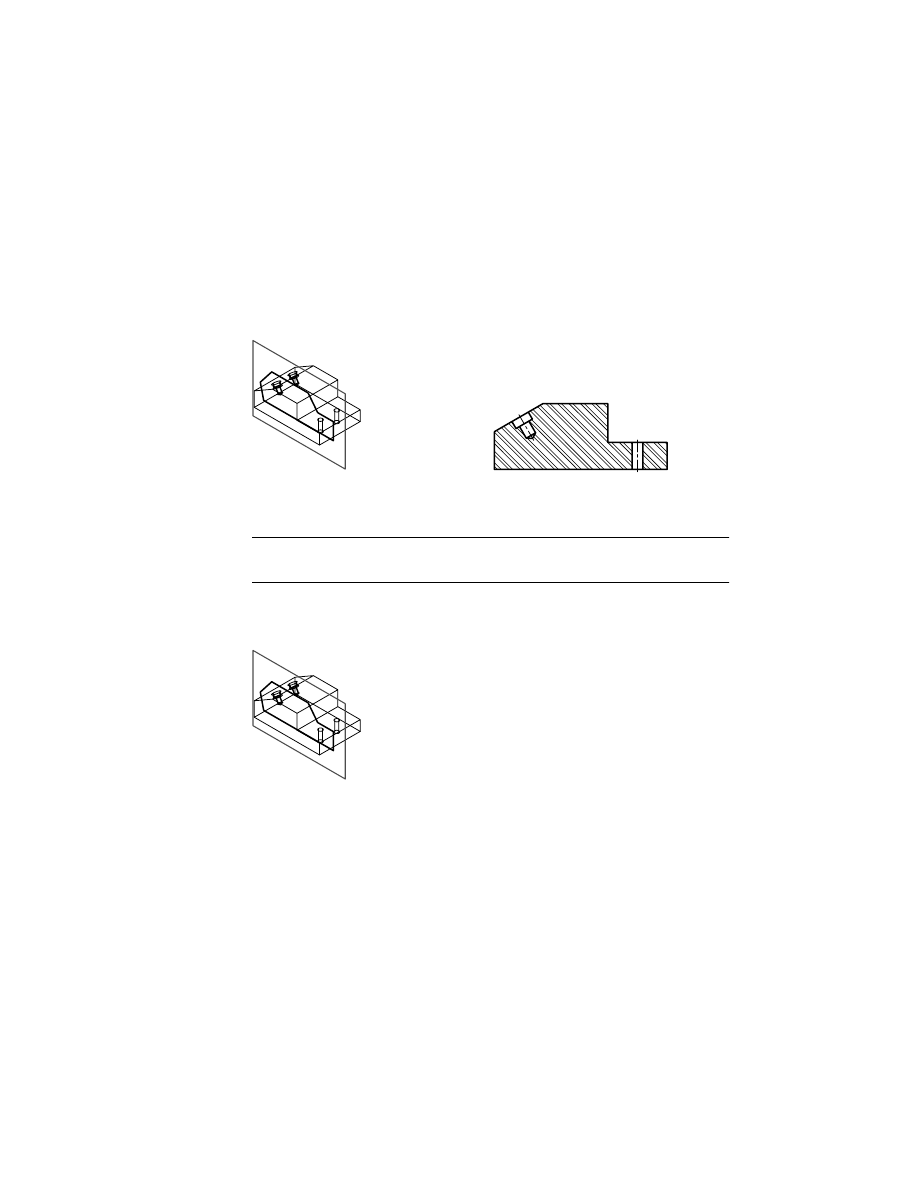
section view
offset cut line
section view
aligned cut line
Creating Cut Line Sketches
|
73
In the following exercise, after you create a cut line sketch on these models,
the resulting cross-section drawing views can be generated in Drawing mode.
A cut line sketch is needed when you want to define a custom cross-section
view only, but not for a half or full cross-section view.
Open the file sketch3.dwg in the desktop\tutorial folder. The drawing contains
two parts.
NOTE
Back up the tutorial drawing files so you still have the original files if you
make a mistake. See “Backing up Tutorial Drawing Files” on page 40.
Before you begin, click the plus signs in front of SKETCH3 and PART1_1 to
expand the Browser hierarchy.
74
|
Chapter 6
Creating Parametric Sketches
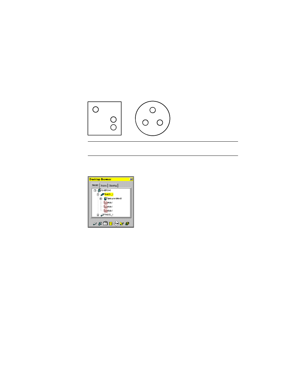
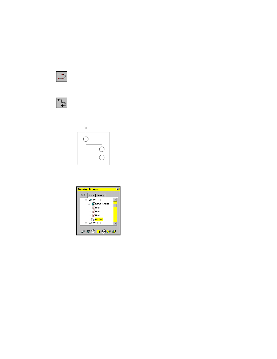
To create an offset cut line sketch
1
Use
PLINE
to sketch through the center of the holes on the square part.
Context Menu
In the graphics area, right-click and choose 2D Sketching
➤ Polyline.
Next, analyze the cut line sketch according to internal sketching rules.
2
Use
AMCUTLINE
to solve the cut line, responding to the prompts.
Context Menu
In the graphics area, right-click and choose Sketch Solving
➤ Cut Line.
Select objects to define the section cutting line:
Select the polyline (1)
Select objects to define the section cutting line:
Press
ENTER
A new icon called CutLine1 is added to the PART1_1 hierarchy in the
Browser.
Save your file.
1
Creating Cut Line Sketches
|
75
As with the other sketches you created, a message tells you how many dimen-
sions and constraints are needed to fully solve the sketch. In this case, you
need five dimensions or constraints to complete the definition of the sketch:
three to define the shape of the sketch, and two to constrain it to the part.
When you create a cross-section drawing view, this sketch defines the path
of the cut plane. If you change the size of the part or holes, or their place-
ment, the cut line is updated to reflect the new values.
For the next exercise, you use the circular part. In the Browser, click the
minus sign in from of PART1_1 to collapse the part hierarchy. Then click the
plus sign in front of PART2_1 to expand the circular part hierarchy.
Before you begin, you need to activate the circular part.
Browser
Double-click PART2_1.
PART2_1 is activated, and highlighted in the Browser and on your screen.
NOTE
Before you can work on a part, it must be active.

76
|
Chapter 6
Creating Parametric Sketches
To create an aligned cut line sketch
1
Use
PLINE
to sketch through the centers of two of the holes on the circular
part.
Context Menu
In the graphics area, right-click and choose 2D Sketching
➤ Polyline.
2
Define a cut line on your sketch, responding to the prompts.
Context Menu
In the graphics area, right-click and choose Sketch Solving
➤ Cut Line.
Select objects to define the section cutting line:
Select the polyline (2)
Select objects to define the section cutting line:
Press
ENTER
A message states that you need five dimensions or constraints to fully solve
this sketch.
3
In the Browser, the new CutLine1 icon is part of the PART2_1 hierarchy.
Save your file.
2
Creating Split Line Sketches
|
77
Creating Split Line Sketches
A molded part or casting usually requires two or more shapes to define the
part. To make a mold or a cast, you create the shape of your part and then
apply a split line to split the part into two or more pieces. You may also need
to apply a small draft angle to the faces of your part so that your part can be
easily removed from the mold.
Split lines can be as simple as a planar intersection with your part, or as com-
plex as a 3D polyline, or spline, along planar or curved faces.
You can also split parts using either
■
A selected planar face or a work plane
■
A sketch projected onto a selected set of faces
In this exercise, you create a split line to split a shelled part into two separate
parts.
Open the file sketch4.dwg in the desktop\tutorial folder.
NOTE
Back up the tutorial drawing files so you still have the original files if you
make a mistake. See “Backing up Tutorial Drawing Files” on page 40.
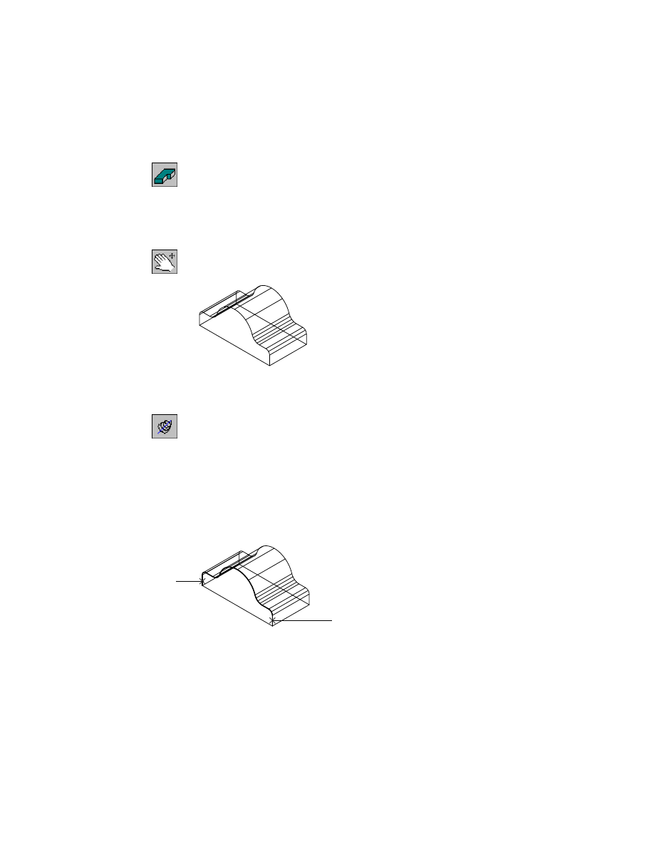
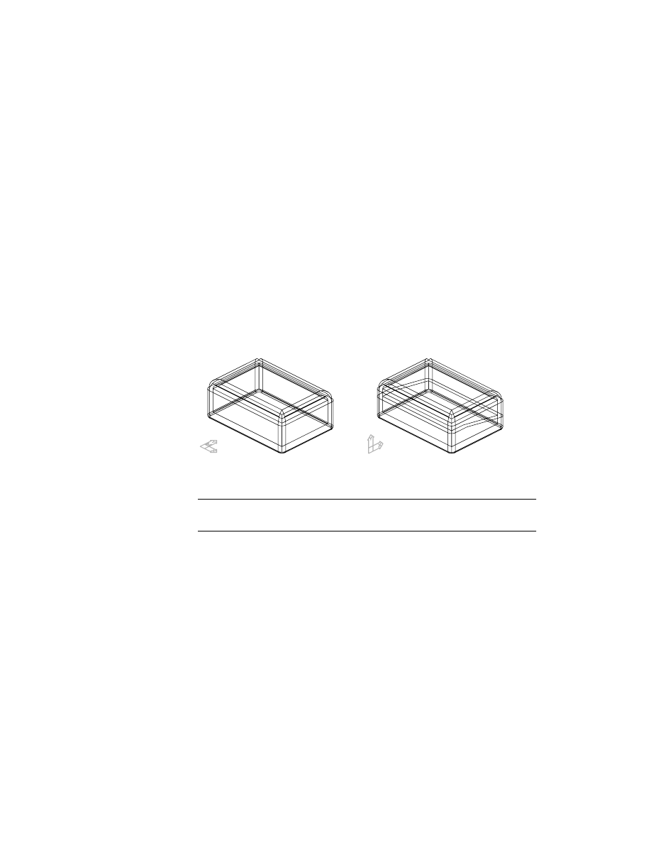
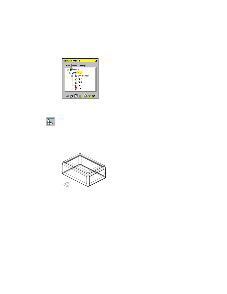
The drawing file contains a simple shelled box. Two viewports have been
defined: the right side of the part, and an isometric view. You’ll define a new
sketch plane in the right viewport and sketch a split line in the left viewport.
shelled part
split part
78
|
Chapter 6
Creating Parametric Sketches
To create a split line
1
Expand the Browser hierarchy of SKETCH4 and PART1_1.
The part consists of an extrusion, three fillets, and a shell feature. Next, you
create a sketch plane on the outside right face of the part.
2
In the right viewport, define a new sketch plane, responding to the prompts.
Context Menu
In the graphics area, right-click and choose New Sketch
Plane.
Select work plane, planar face or [worldXy/worldYz/worldZx/Ucs]:
Specify the outside right face of the part (1)
Enter an option [Accept/Next] <Accept>:
Press
ENTER
Plane = Parametric
Select edge to align X axis [Flip/Rotate/Origin] <accept>:
Press
ENTER
Next, create a sketch and convert it to a split line.
1
Creating Split Line Sketches
|
79
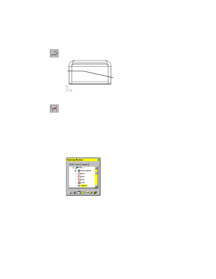
3
In the left viewport, use
PLINE
to sketch the split line.
Context Menu
In the graphics area, right-click and choose 2D Sketching
➤ Polyline.
4
Use
AMSPLITLINE
to create a split line from your sketch, responding to the
prompts.
Context Menu
In the graphics area, right-click and choose Sketch Solving
➤ Split Line.
Select objects for sketch:
Select the polyline
Select objects for sketch:
1 found
Select objects for sketch:
Press
ENTER
Select edge to include in split line or press <ENTER> to accept:
Press
ENTER
Mechanical Desktop solves the sketch and displays the number of constraints
required to fully constrain it.
Solved underconstrained sketch requiring 5 dimensions or constraints.
5
Look at the Browser. SplitLine1 is now nested under the part definition.
Save your file.
80
|
Chapter 6
Creating Parametric Sketches
Creating Break Line Sketches
When you want to document complex assemblies, it is not always easy to dis-
play parts and subassemblies that are hidden by other parts in your drawing
views. By creating a break line sketch, you can specify what part of your
model will be cut away in a breakout drawing view so that you can illustrate
the parts behind it.
Open the file sketch4a.dwg in the desktop\tutorial folder.
NOTE
Back up the tutorial drawing files so you still have the original files if you
make a mistake. See “Backing up Tutorial Drawing Files” on page 40.
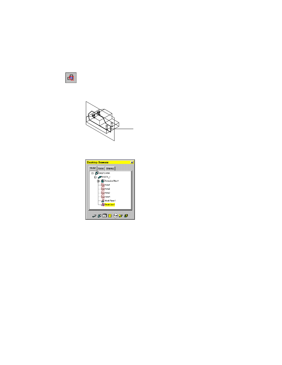
The drawing file contains a simple part. An unsolved sketch lies on a work
plane. You create a break line from this sketch.
break line path
breakout drawing view
Creating Break Line Sketches
|
81
To create a break line
1
Use
AMBREAKLINE
to define the break line sketch, following the prompts.
Context Menu
In the graphics area, right-click and choose Sketch Solving
➤ Break Line.
Select objects for sketch:
Specify the sketch (1)
Select objects for sketch:
Press
ENTER
The break line is created. The Browser contains a break line icon nested below
the work plane.
Save your file.
Now that you have learned the basics of creating sketches, you are ready to
constrain them by adding geometric and parametric dimension constraints.
1

82
Wyszukiwarka
Podobne podstrony:
Parametry życiowe dla WCEM
ch6 030702
PARAMETRY STATYSTYCZNE Aktualne
Obliczanie i pomiary parametrów obwodów prądu jednofazowego
Zwiazki korelacyjne parametrow zageszczenia wyznaczonych VSS i LFG
Instrukcja 07 Symbole oraz parametry zaworów rozdzielających
05 Pomiar paramet zrodel U I
dobór parametru klotoidy
CH6
parametry.prv, fizjologia notatki
Hipoteza o istotności parametrów strukturalnych, Wykłady rachunkowość bankowość
Urządzenia 101 - parametry łączników protokół (tylko dla ZAO, Politechnika Lubelska, Studia, semestr
Gubin parametry, AGH, Semestr X, stateczność skarp i zboczy, Stateczność skarp TOEZ
Gen Czaban brakuje zapisu z rejestratora parametrów lotu
sprawozdanie mikroklimat i pomiary jego parametrów w środowisku górniczym
3 Parametry i usługi sieci dostępu do Internetu – teraz i w przyszłości
Podać podstawowe parametry znamionowe przekładnika prądowego
Czym się różnią czujniki generacyjne od parametrycznych
więcej podobnych podstron