

6/0

6/1
Contents
0
6
6 - Zelio Relay - plug-in relays
and interfaces for discrete signals
Selection guide . . . . . . . . . . . . . . . . . . . . . . . . . . . . . . . . . . . . . . . . . . . . . page 6/2
Zelio Relay - plug-in relays
b RSB interface relays
v Presentation, characteristics . . . . . . . . . . . . . . . . . . . . . . . . . . . . . . . . page 6/4
v References . . . . . . . . . . . . . . . . . . . . . . . . . . . . . . . . . . . . . . . . . . . . . page 6/6
b RXM miniature relays
v Presentation, characteristics . . . . . . . . . . . . . . . . . . . . . . . . . . . . . . . . page 6/8
v References . . . . . . . . . . . . . . . . . . . . . . . . . . . . . . . . . . . . . . . . . . . . page 6/11
b RUM universal relays
v Presentation, characteristics . . . . . . . . . . . . . . . . . . . . . . . . . . . . . . . page 6/16
v References . . . . . . . . . . . . . . . . . . . . . . . . . . . . . . . . . . . . . . . . . . . . page 6/19
b RPM power relays
v Presentation, characteristics . . . . . . . . . . . . . . . . . . . . . . . . . . . . . . . page 6/24
v References . . . . . . . . . . . . . . . . . . . . . . . . . . . . . . . . . . . . . . . . . . . . page 6/27
b RPF power relays
v Presentation, characteristics . . . . . . . . . . . . . . . . . . . . . . . . . . . . . . . page 6/32
v References . . . . . . . . . . . . . . . . . . . . . . . . . . . . . . . . . . . . . . . . . . . . page 6/34
b Technical presentation . . . . . . . . . . . . . . . . . . . . . . . . . . . . . . . . . . . . . page 6/36
Interfaces for discrete signals
Selection guide . . . . . . . . . . . . . . . . . . . . . . . . . . . . . . . . . . . . . . . . . . . . page 6/38
b Electromechanical interface modules
v Presentation, characteristics . . . . . . . . . . . . . . . . . . . . . . . . . . . . . . . page 6/40
v References . . . . . . . . . . . . . . . . . . . . . . . . . . . . . . . . . . . . . . . . . . . . page 6/44
b Slim electromechanical interface modules
v Presentation, characteristics . . . . . . . . . . . . . . . . . . . . . . . . . . . . . . . page 6/46
v References . . . . . . . . . . . . . . . . . . . . . . . . . . . . . . . . . . . . . . . . . . . . page 6/50
b Slim solid-state interface modules
v Presentation, characteristics . . . . . . . . . . . . . . . . . . . . . . . . . . . . . . . page 6/52
v References . . . . . . . . . . . . . . . . . . . . . . . . . . . . . . . . . . . . . . . . . . . . page 6/56
6/2
6
Selection guide
6
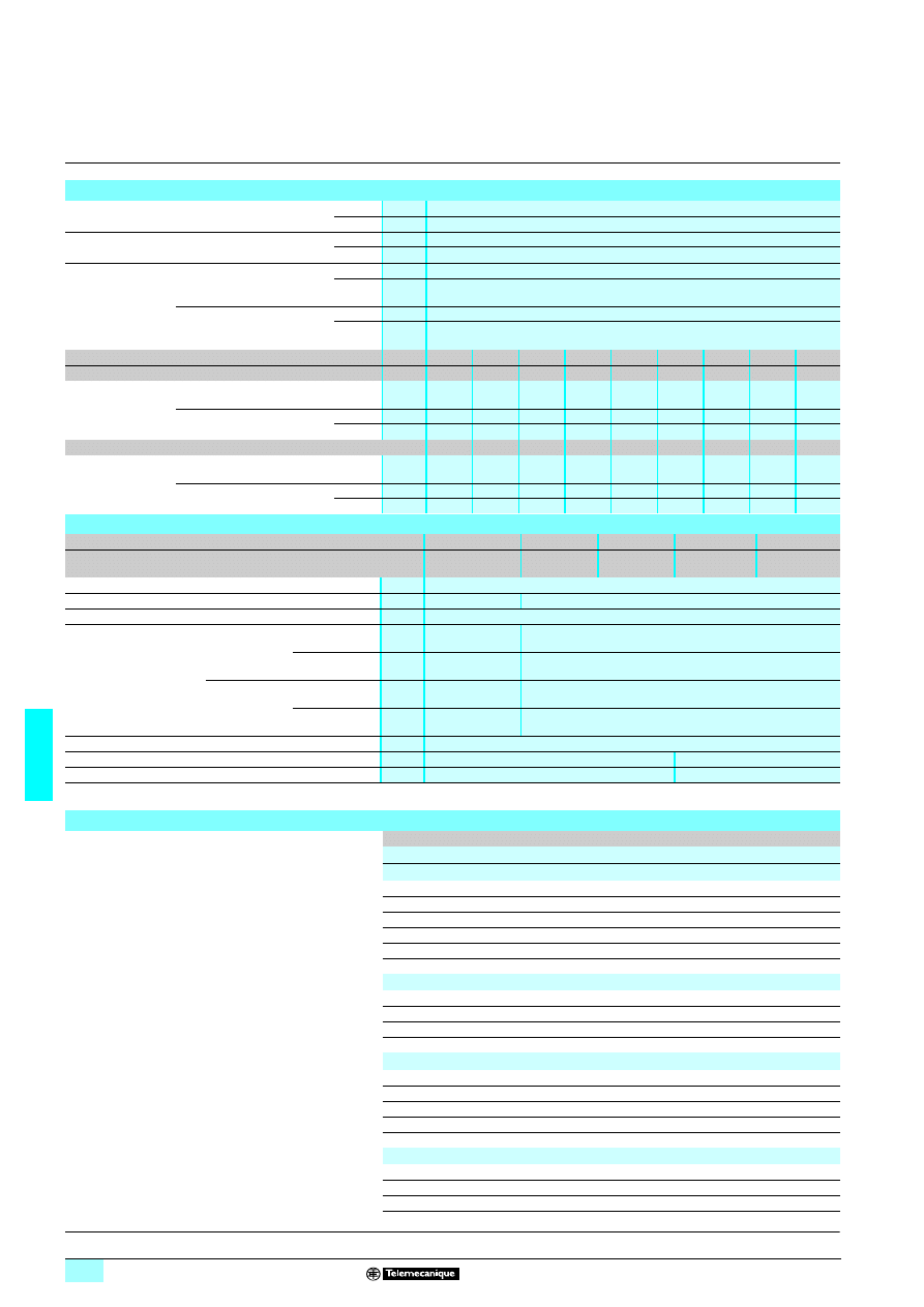
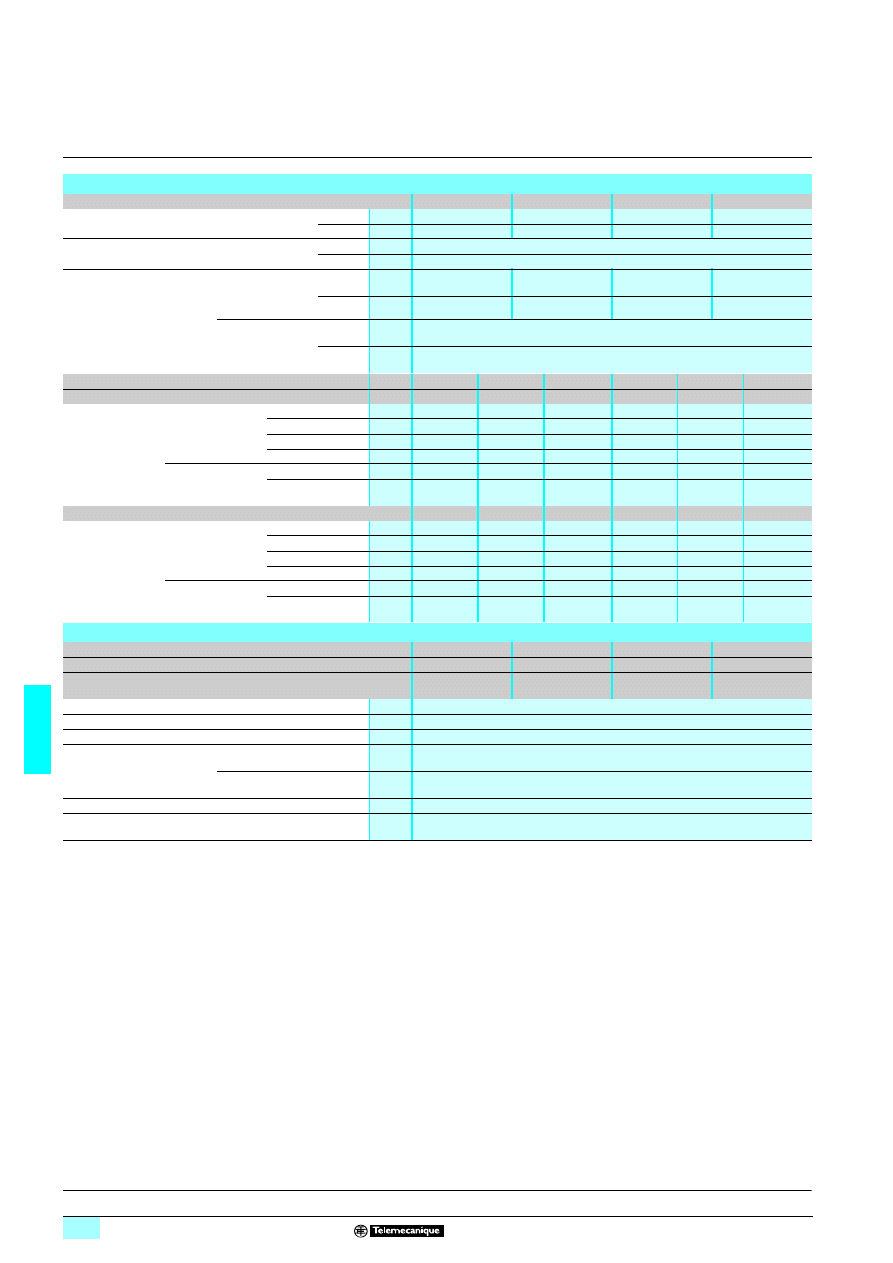
Zelio Relay - plug-in relays
6
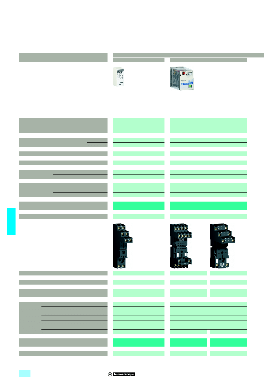
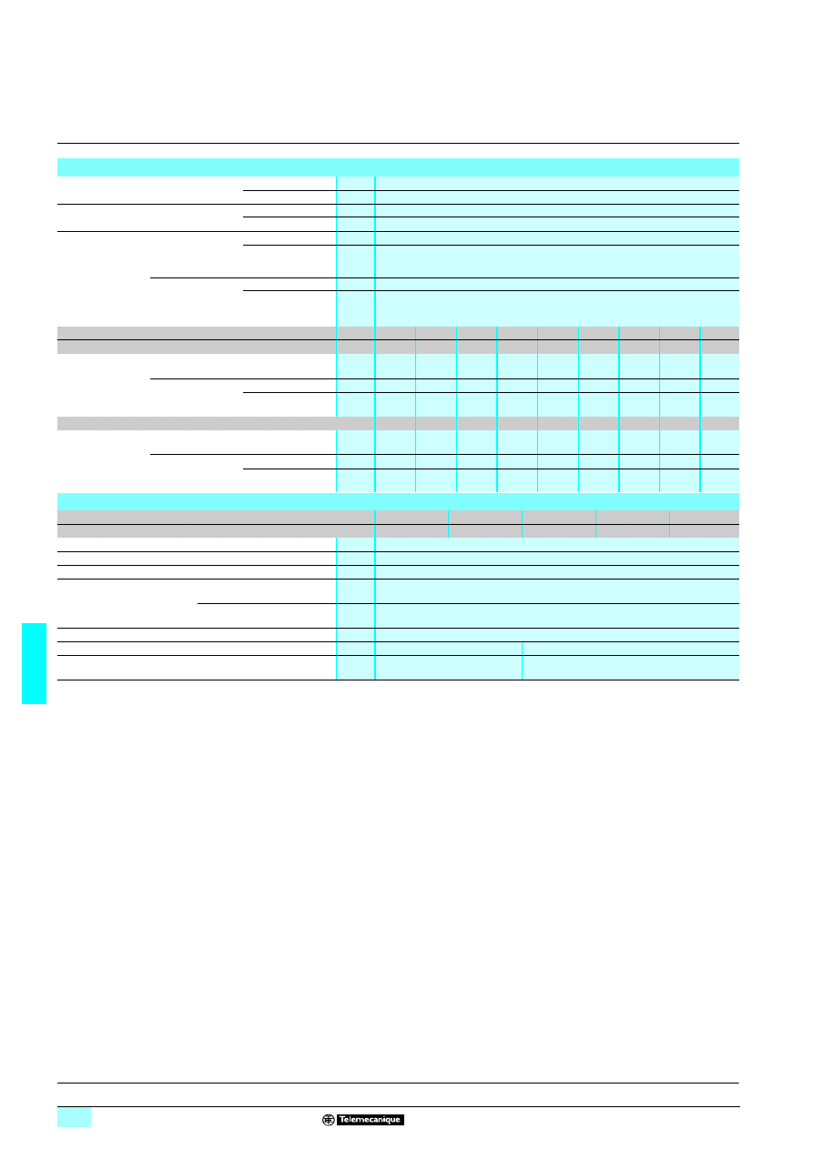
Application
Plug-in relays
Interface relays
Miniature relays
Number and type of contacts / conventional thermal
current (Ith on N/O contact)
1 C/O / 16 A
1 C/O / 12 A
2 C/O / 8 A
2 C/O / 12 A
3 C/O / 10 A
4 C/O / 6 A
4 C/O / 3 A (low level)
Control circuit voltage
a
24…240 V
24…240 V
c
6…110 V
12…220 V
Type of pins
Flat (Faston type)
Flat (Faston type)
Operational voltage
Up to a 400 V / c 300 V
Up to 250 V
Durability
(operating cycles)
Electrical, resistive load
100 000
100 000
Mechanical, no-load
30 000 000
10 000 000
Functions
LED
Yes (with protection modules)
Yes (depending on version)
Test button and mechanical indicator
–
Yes
Low level contacts
–
Yes
Type reference
RSB
RXM
Pages
6/6
6/11 and 6/12
Conventional thermal current (Ith)
12 A (1)
10 A
12 A (2)
Contact terminal arrangements
Separate
Mixed
Separate
Connection
Connector
Screw clamp terminals
or connector
Connector
Accessories Protection modules
Yes
Yes
Timer module
–
–
Maintaining clamps
Yes
Yes
Socket identification legend
Yes
Yes (except RXZ E2M114)
Mounting adapters
for
5 rail
–
Yes
Mounting adapters with fixing lugs
–
Yes
Bus jumper, 2-pole (Ith = 5 A)
–
–
Yes
Associated socket types
RSZ E1SppM
RXZ E2Mppp
RXZ E2Sppp
Pages
6/6
6/12
6/12
(1) When using relay RSB 1A160
pp
with socket RSZ E1S48M, terminals must be linked.
(2) Except for sockets RXZ E2S11
p
M: 10 A.
6/3
6
6
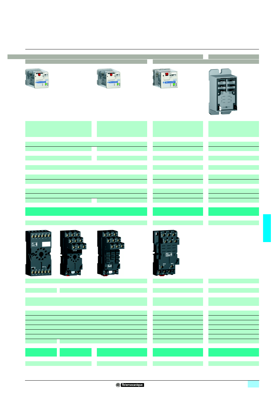
Relays with clamp fixing
Universal relays
Power relays
2 C/O / 10 A
3 C/O / 10 A
3 C/O / 3 A (low level)
2 C/O / 10 A
3 C/O / 10 A
1 C/O / 15 A
2 C/O / 15 A
3 C/O / 15 A
4 C/O / 15 A
2 N/O / 30 A (3)
2 C/O / 30 A (3)
24…230 V
24…230 V
24…240 V
12…220 V
12…110 V
12…110 V
12…125 V
Cylindrical
Flat (Faston type)
Flat (Faston type)
Flat (Faston type)
Up to 250 V
Up to 250 V
Up to 250 V
100 000
100 000
50 000
5 000 000
10 000 000
5 000 000
Yes (depending on version)
Yes (depending on version)
–
Yes
Yes
–
Yes
–
–
–
RUM
RPM
RPF
6/19
6/27
6/34
12 A
16 A
–
Mixed
Separate
Mixed
–
Connector
Screw clamp terminals
–
Yes
Yes
–
Yes
Yes (for 3 and 4-pole)
Yes
Yes (on socket RPZ F1)
–
Yes
Yes
–
–
Yes
–
–
Yes
–
–
Yes
–
–
RUZ CpM
RUZ SCpM
RUZ SF3M
RPZ Fp
–
6/20
6/20
6/28
–
(3) 30 A when mounted with 13 mm gap between two relays and 25 A when mounted side by side without a gap.
6/4
6
Presentation,
characteristics
6
Zelio Relay - plug-in relays
6
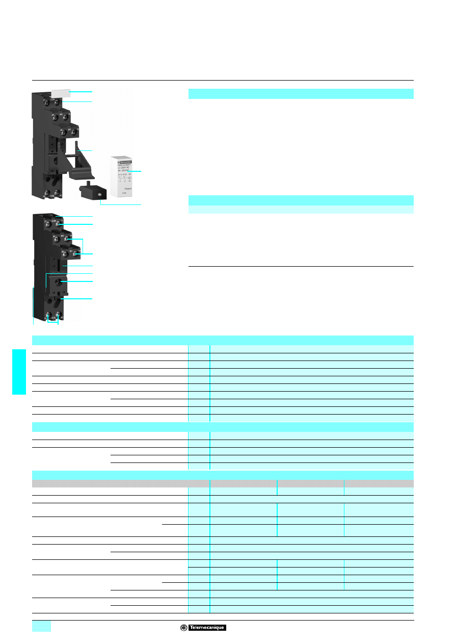
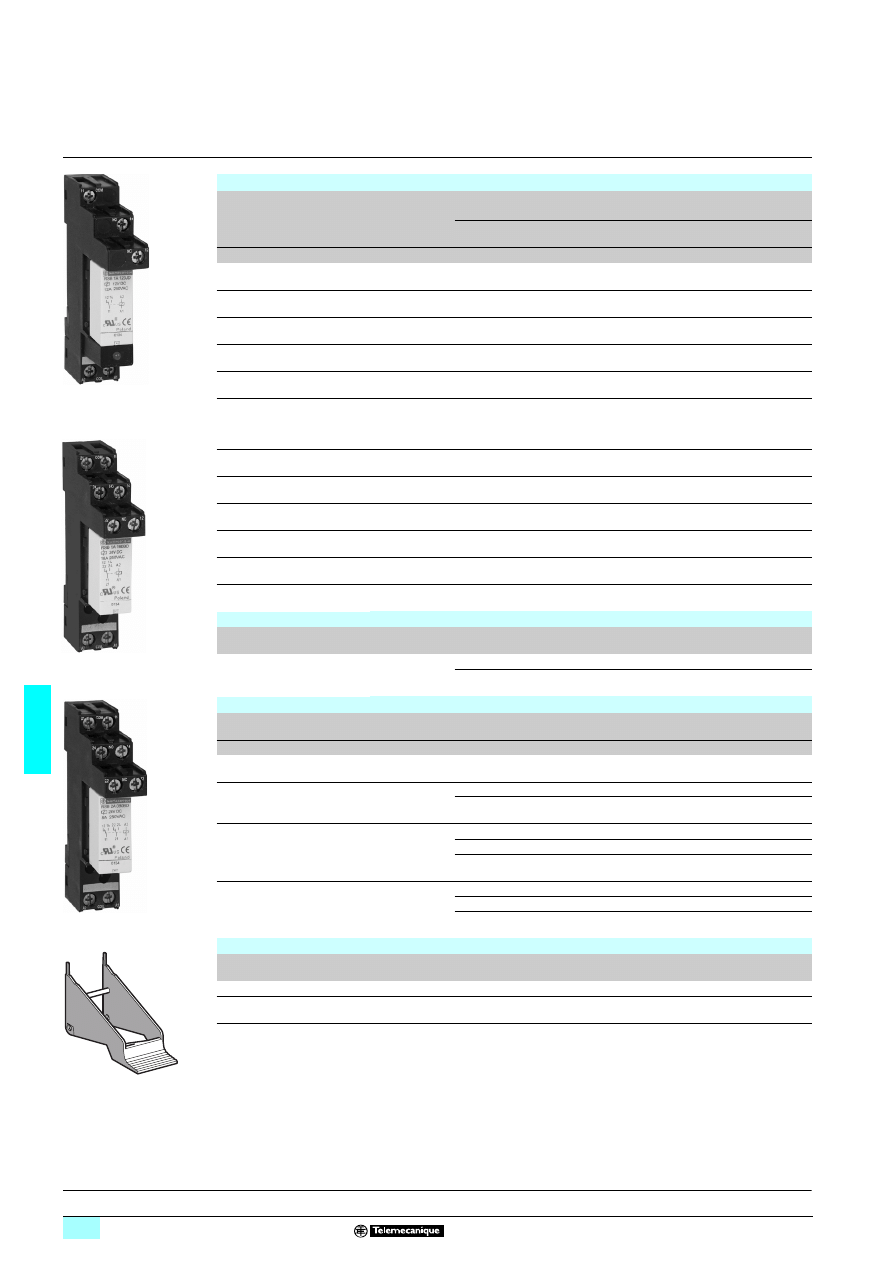
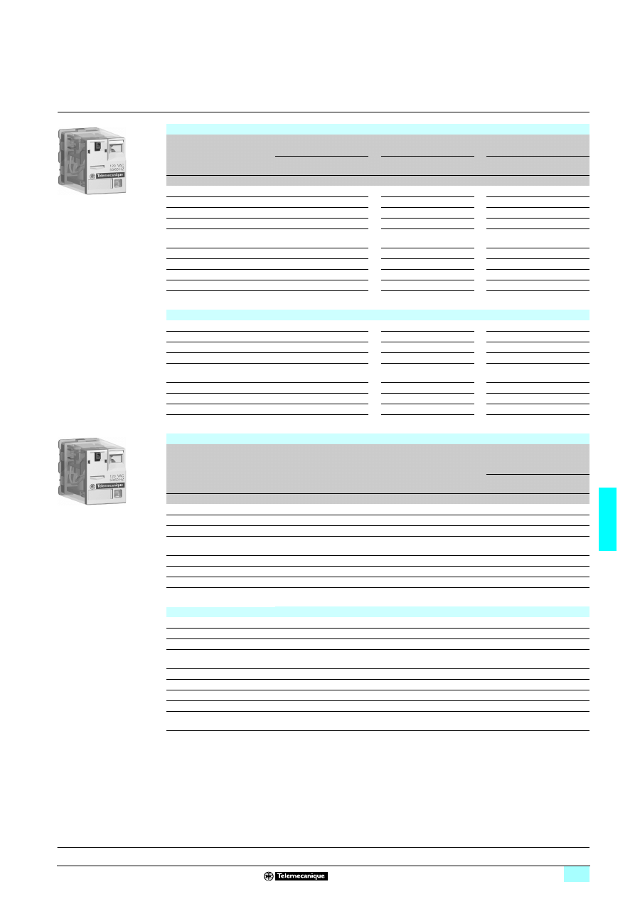
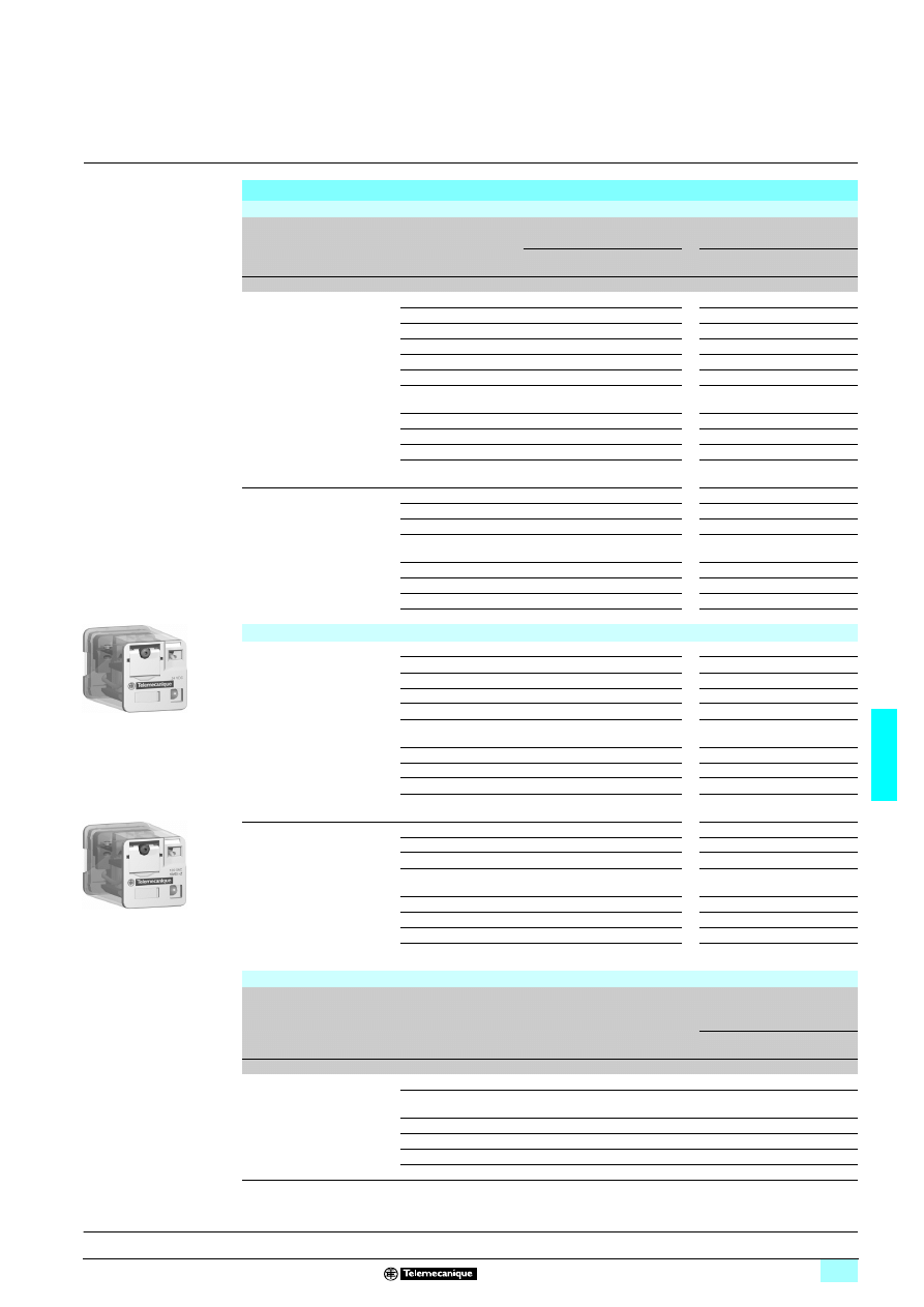
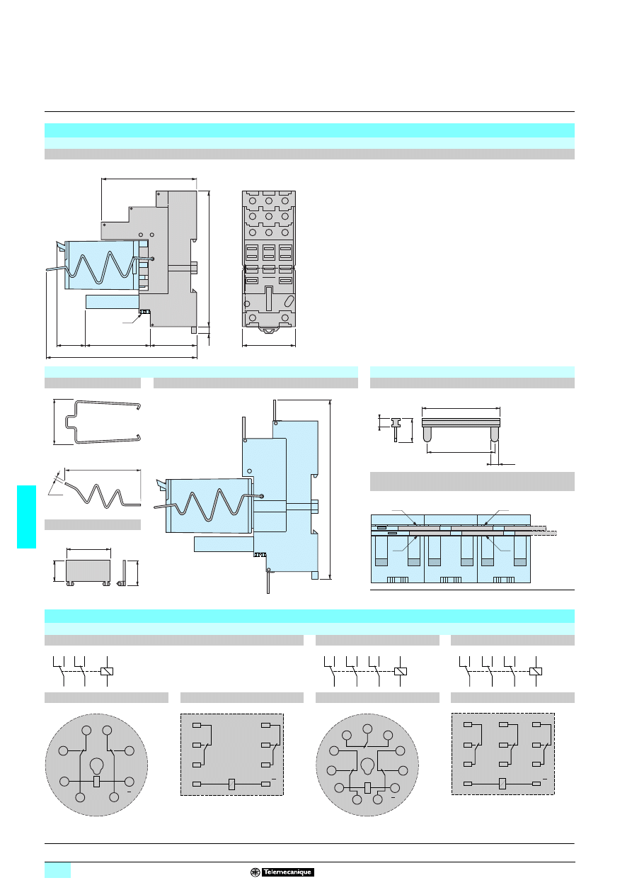
RSB interface relays
The RSB interface relay range comprises:
1
12 A relays with1 C/O contact , 16 A relays with 1 C/O contact and 8 A relays with
2 C/O contacts.
2
Sockets with separate contact terminals.
3
Protection modules (diode, diode + LED, RC circuit or varistor + LED). All these
modules are common to all sockets.
4
A plastic maintaining clamp for all sockets.
5
Clip-in legends for the sockets.
1
Connection by connector.
2
Five or eight female contacts for the relay pins.
3
A fixing hole for panel mounting.
4
Location for protection modules.
5
Locking components for plastic maintaining clamp.
6
Locating slot for mounting on 5 rail.
(1) The inputs and outputs are separate from the relay supply.
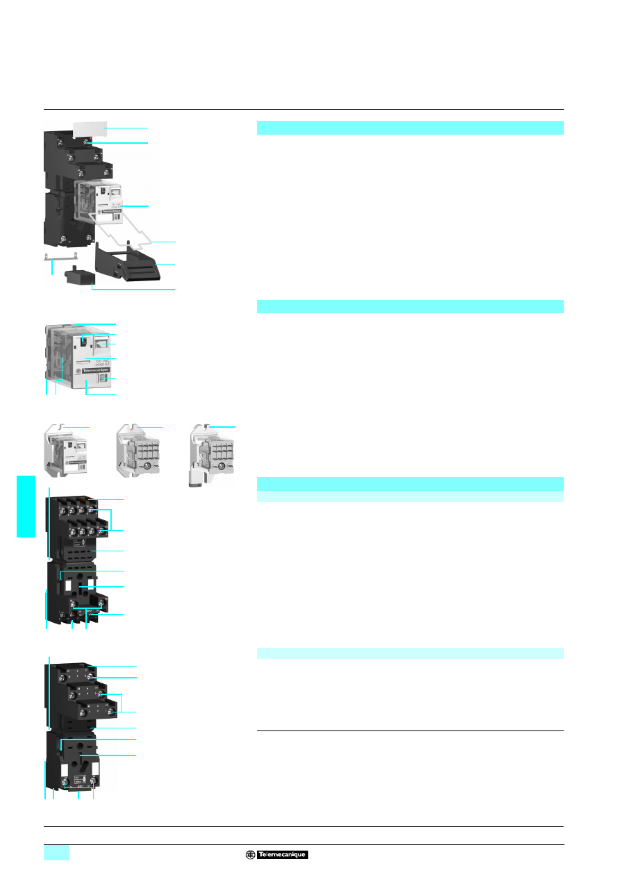
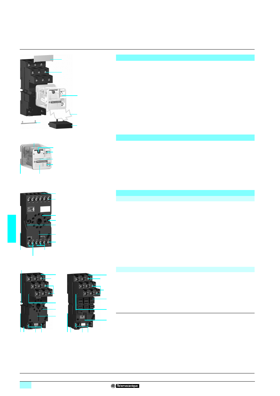
Presentation of the range
5
4
1
523
139
2
3
Socket description
Sockets with separate contact terminals (1)
5351
88
1
2
3
5
6
4
Inputs
Outputs
Relay supply
General characteristics
Conforming to standards
IEC/EN 61810-1, UL 508, CSA C22-2 n° 14
Product certifications
UL, CSA
Ambient air temperature
around the device
Storage
°C
- 40…+ 85
Operation
°C
c - 40…+ 85, a - 40...+ 70
Vibration resistance
Conforming to IEC/EN 60068-2-6
> 10 gn (10…150 Hz)
Degree of protection
Conforming to IEC/EN 60529
IP 40
Shock resistance
conforming to IEC/EN 60068-2-27
Opening
5 gn
Closing
10 gn
Protection category
RT I
Mounting position
Any
Insulation characteristics
Rated insulation voltage (Ui)
Conforming to IEC/EN 60947
V
400
Rated impulse withstand voltage (Uimp)
kV
3.6 (1.2/50 µs)
Dielectric strength
(rms voltage)
Between coil and contact
a V
5000
Between poles
a V
2500
Between contacts
a V
1000
Contact characteristics
Relay type
RSB 1A120pp
RSB 1A160pp
RSB 2A080pp
Number and type of contacts
1 C/O
1 C/O
2 C/O
Contact materials
AgNi
Conventional thermal current
(Ith)
For ambient
temperature y 40°C
A
12
16
8
Rated operational current
in utilisation categories
AC-1 and DC-1
Conforming to IEC
N/O
A
12
16
8
N/C
A
6
8
4
Switchable current
Minimum
mA
5
Switching voltage
Maximum
V
a 400, c 300
Minimum
V
5
Rated load (resistive)
A
12 / 250 a V
16 / 250 a V
8 / 250 a V
A
12 / 28 c V
16 / 28 c V
8 / 28 c V
Switching capacity
Maximum
a
VA
3000
4000
2000
c
W
336
448
224
Minimum
mW
300
Maximum operating rate
In operating cycles/hour
No-load
72 000
Under load
600
6/5
6
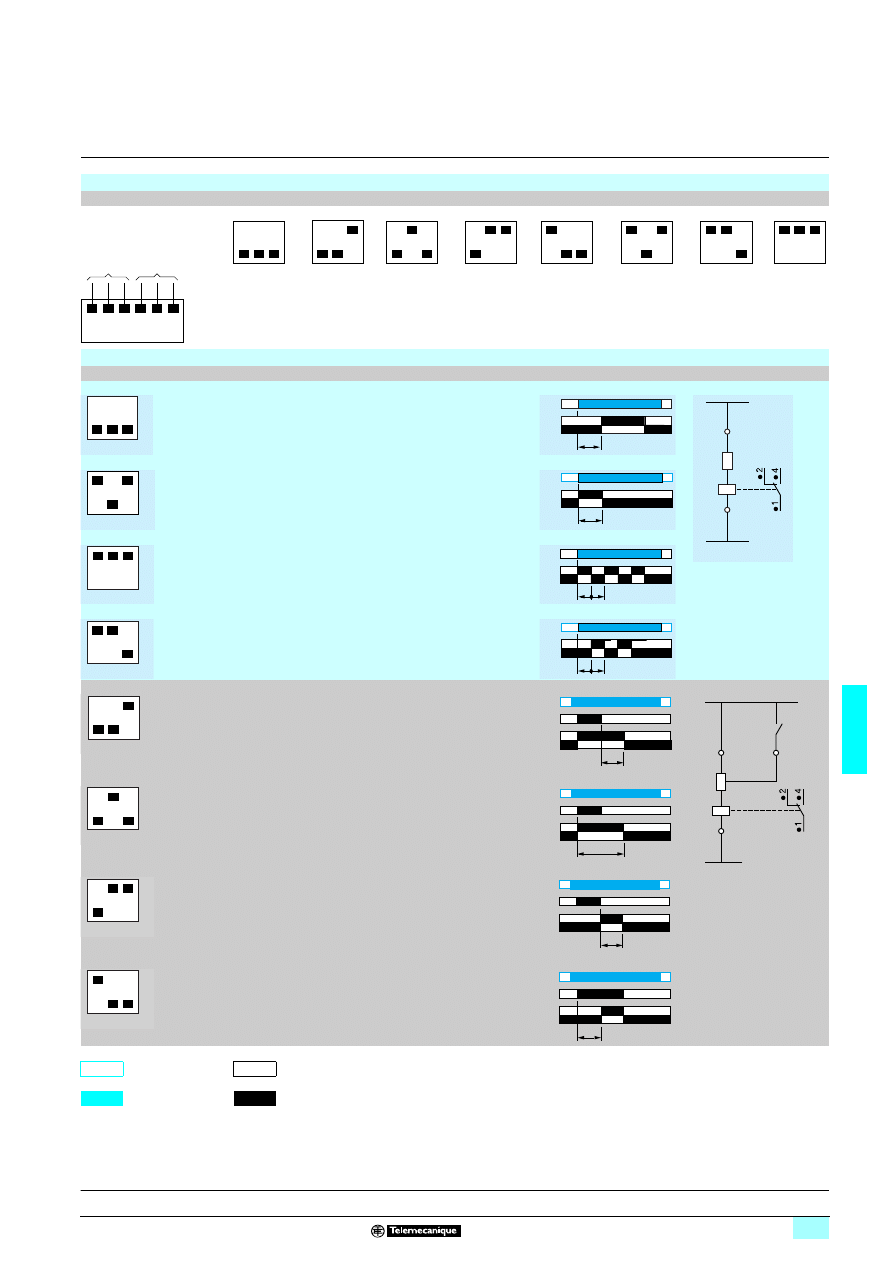
Characteristics
6
Zelio Relay - plug-in relays
6
RSB interface relays
(1) When using the relay with socket RSZ E1S48M, terminals must be linked. See connection
schemes on page 6/7.
Contact characteristics
(continued)
Relay type
RSB 1A120pp
RSB 1A160pp
RSB 2A080pp
Mechanical durability
In millions of operating cycles
u 30
Electrical durability
In millions of operating
cycles
Resistive load
12 A - 250 V: u 0.1
16 A - 250 V: u 0.07
8 A - 250 V: u 0.1
Inductive load
See curves below
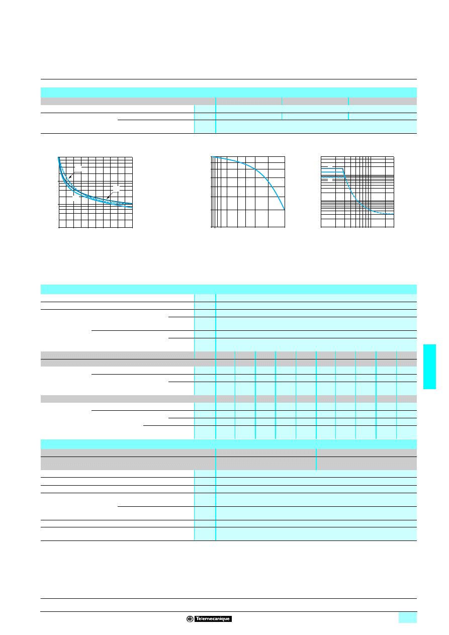
Electrical durability of contacts
Resistive load a
Reduction coefficient for inductive load a
(depending on power factor cos
ϕ)
Maximum switching capacity on resistive load
c
A
RSB 2A080pp
B
RSB 1A160pp
C
RSB 1A120pp
Durability (inductive load) = durability (resistive load) x reduction coefficient.
Coil characteristics
Average consumption
c 0.45 W, a 0.75 VA
Drop-out voltage threshold
≥ c 0.1 Uc, ≥ a 0.15 Uc
Operating time
(response time)
Between coil energisation
and making of the
On-delay contact
a
ms
About 12
c
ms
About 9
Between coil de-energisation
and making of the
Off-delay contact
a
ms
About 10
c
ms
About 4
Control circuit voltage Uc
V
6
12
24
48
60
110
120
220
230
240
Relay control voltage codes
RD
JD
BD
ED
ND
FD
–
–
–
–
DC
Average resistance at 20 °C ± 10%
Ω
90
360
1440
5700
7500
25 200 –
–
–
–
Operating
voltage limits
Min.
V
4.8
9.6
19.2
38.4
48
88
–
–
–
–
Max.
V
6.6
13.2
26.4
52.8
66
121
–
–
–
–
Relay control voltage codes
–
–
B7
E7
–
–
F7
M7
P7
U7
AC
50/60 Hz
Average resistance at 20 °C ± 15%
Ω
–
–
400
1550
–
–
10 200 35 500 38 500 42 500
Operating
voltage limits
Min.
50 Hz
V
–
–
19.2
38.4
–
–
96
176
184
192
60 Hz
–
–
20.4
40.8
–
–
102
187
195.5
204
Max.
50/60 Hz
V
–
–
26.4
57.6
–
–
144
264
276
288
Socket characteristics
Socket type
RSZ E1S35M
RSZ E1S48M
Relay types used
RSB 1A120pp
RSB 2A080pp
RSB 1A160pp (1)
Product certifications
UL, CSA
Conventional thermal current (Ith)
A
12
Degree of protection
Conforming to IEC/EN 60529
IP 20
Connection
Solid cable without cable end
mm
2
1 conductor: 0.5…2.5 mm
2
(AWG 20…AWG 14)
2 conductors: 0.5…1.5 mm
2
(AWG 20…AWG 16)
Flexible cable with cable end
mm
2
1 conductor: 0.2…2.5 mm
2
(AWG 24…AWG 14)
2 conductors: 0.2…1.5 mm
2
(AWG 24…AWG 16)
Maximum tightening torque
Nm
0.6 (M3 screw)
Contact terminal arrangement
Separate
104
0,8
0
0,4
1,2
1
1,6
2
107
105
106
C
A
B
D
u
rabi
lity
(
N
umber
of op
er
at
ing c
y
c
les
)
Switching capacity (kVA)
0,3
0,5
0,6
10,8
0,4
0,2
0,4
0,6
0,8
1
cos
ϕ
R
educ
ti
on
c
oeffi
c
ient (
A
)
0,1
1
2
16
100
200 300
10
20 30
50
5
8
12
0,5
50
C
B
A
C
u
rr
ent
c
Voltage c
Presentation:
page 6/4
References:
page 6/6
Dimensions, schemes:
page 6/7
6/6
6
References
6
Zelio Relay - plug-in relays
6
RSB interface relays
Relays for standard applications
Control circuit voltage
Sold in
lots of
Number and type of contacts - Thermal current (Ith)
1 C/O -12 A
1 C/O -16 A
2 C/O -8 A
Unit
reference (1)
Unit
reference (1)
Unit
reference (1)
Weight
V
kg
c 6
10
RSB 1A120RD
RSB 1A160RD
RSB 2A080RD
0.014
c 12
10
RSB 1A120JD
RSB 1A160JD
RSB 2A080JD
0.014
c 24
10
RSB 1A120BD
RSB 1A160BD
RSB 2A080BD
0.014
c 48
10
RSB 1A120ED
RSB 1A160ED
RSB 2A080ED
0.014
c 60
10
RSB 1A120ND
RSB 1A160ND
RSB 2A080ND
0.014
c 110
10
RSB 1A120FD
RSB 1A160FD
RSB 2A080FD
0.014
a 24
10
RSB 1A120B7
RSB 1A160B7
RSB 2A080B7
0.014
a 48
10
RSB 1A120E7
RSB 1A160E7
RSB 2A080E7
0.014
a 120
10
RSB 1A120F7
RSB 1A160F7
RSB 2A080F7
0.014
a 220
10
RSB 1A120M7
RSB 1A160M7
RSB 2A080M7
0.014
a 230
10
RSB 1A120P7
RSB 1A160P7
RSB 2A080P7
0.014
a 240
10
RSB 1A120U7
RSB 1A160U7
RSB 2A080U7
0.014
Sockets - 12 A, a 300 V
Contact terminal
arrangement
Connection
Relay type
Sold in
lots of
Unit
reference
Weight
kg
Separate
Connector
RSB 1A120pp
10
RSZ E1S35M
0.060
RSB 1A160pp(2)
RSB 2A080pp
10
RSZ E1S48M
0.050
Protection modules
Description
For
use with
Voltage
Sold in
lots of
Unit
reference
Weight
V
kg
Diode
All sockets
c 6…230
10
RZM 040W
0.003
RC circuit
All sockets
a 24…60
10
RZM 041BN7
0.010
a 110…240
10
RZM 041FU7
0.010
Diode + green LED
All sockets
c 6…24
10
RZM 031RB
0.004
c 24…60
10
RZM 031BN
0.004
c 110…230
10
RZM 031FPD
0.004
Varistor + green LED
All sockets
c or a 6…24
10
RZM 021RB
0.005
c or a 24…60
10
RZM 021BN
0.005
c or a 110…230
10
RZM 021FP
0.005
Accessories
Description
For
use with
Sold in
lots of
Unit
reference
Weight
kg
Plastic maintaining clamp
All sockets
10
RSZ R215
0.002
Legend
All sockets
10
RSZ L300
0.001
(1) To order a relay complete with socket
(sold in lots of 20)
: add suffix S to the references selected above.
Example: RSB 2A080RD + RSZ E1S48M becomes RSB 2A080RDS.
(2) When using the relay with socket RSZ E1S48M, terminals must be linked. See connection schemes on page 6/7.
RSB 1A120JD + RZM 031FPD
+ RSZ E1S35M
560
583
RSB 1A160BD + RSZ E1S48M
56
0584
RSB 2A080BD + RSZ E1S48M
560
582
RSZ R215
56
0585
Presentation:
page 6/4
Characteristics :
pages 6/4 and 6/5
Dimensions, schemes:
page 6/7
6/7
6
Dimensions,
schemes
6
Zelio Relay - plug-in relays
6
RSB interface relays
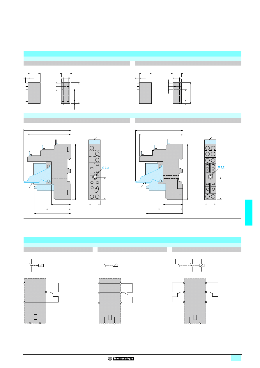
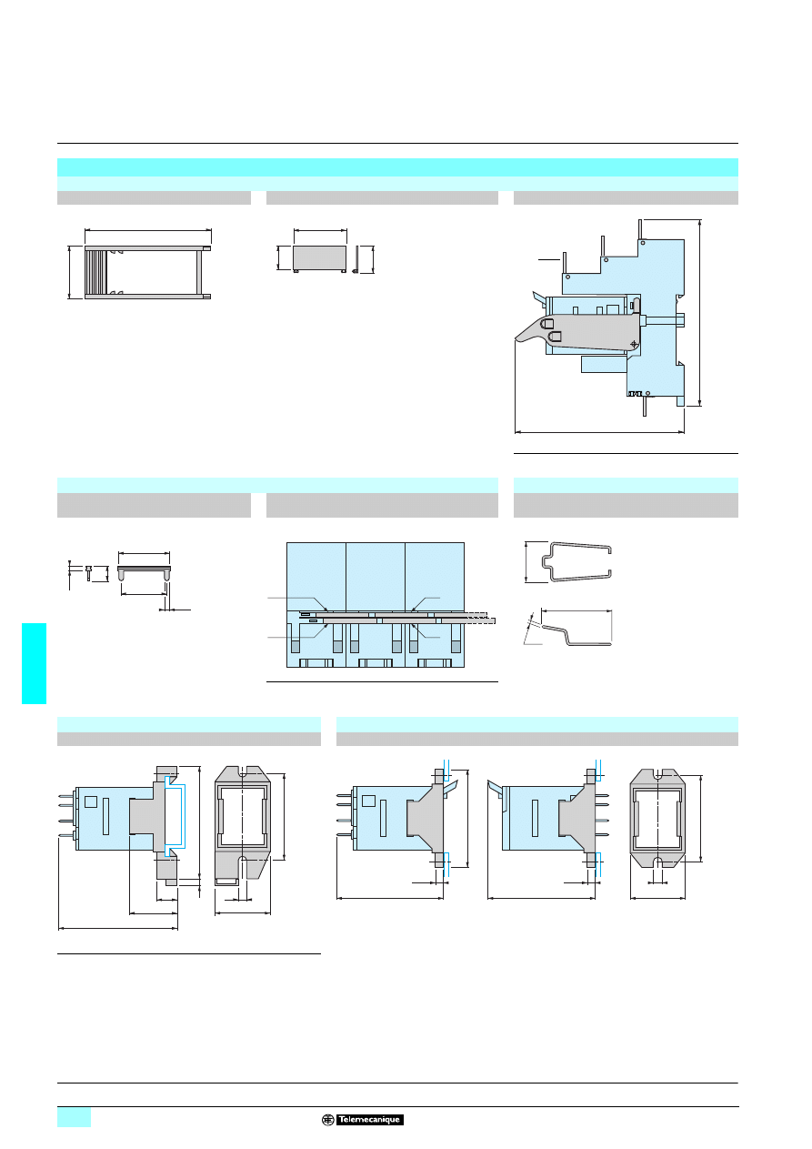
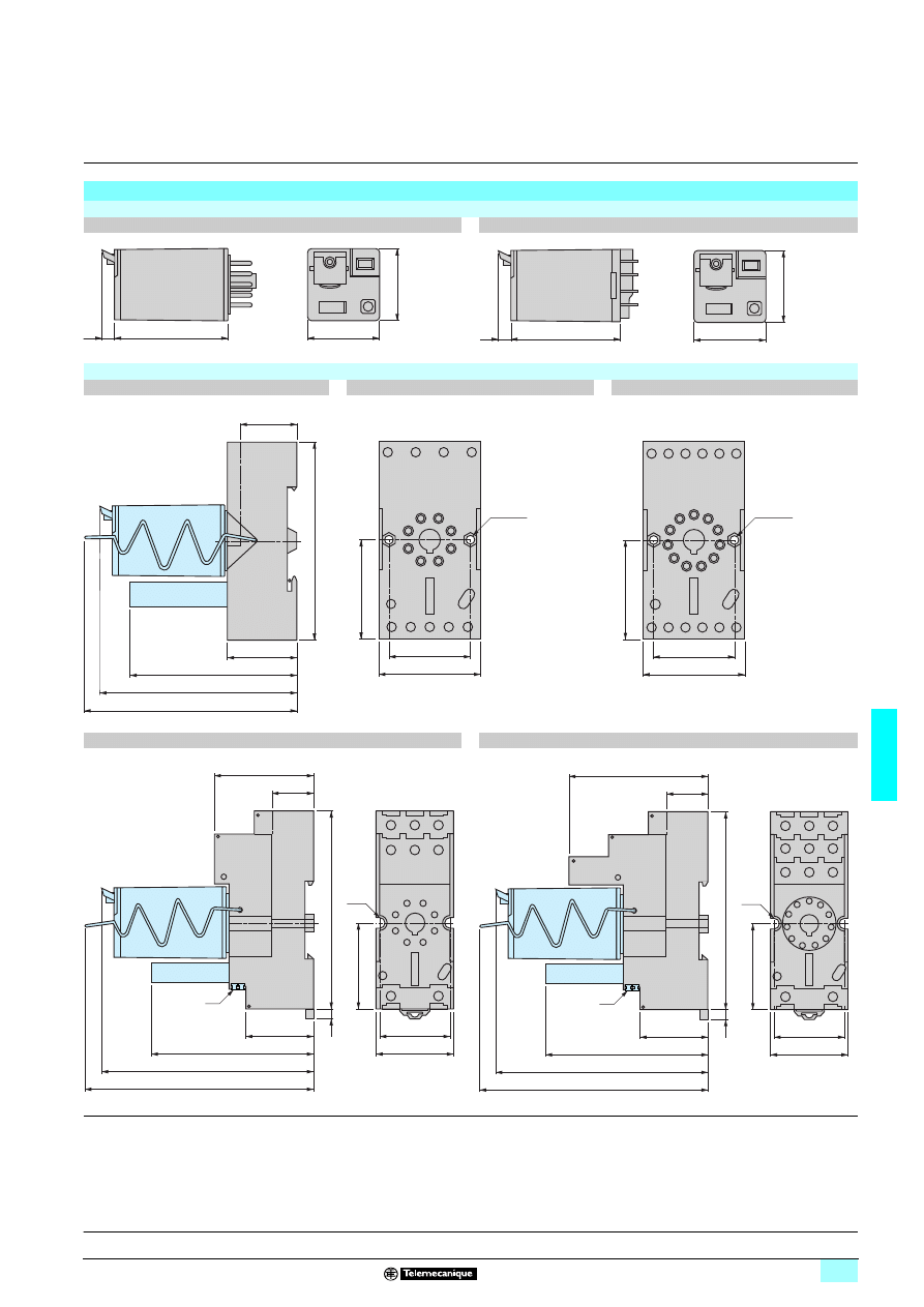
Dimensions
Interface relays
RSB 1A120pp
RSB 2A080pp, RSB 1A160pp
Sockets
RSZ E1S35M
RSZ E1S48M
(1) Relays
(2) Add-on protection module
(3) Maintaining clamp
(4) Legend
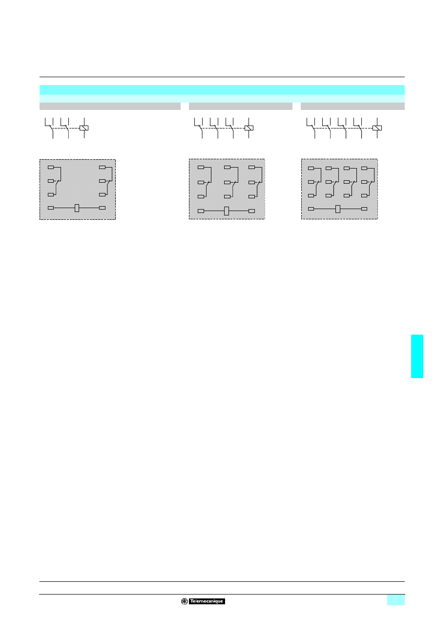
Schemes
Interface relays
RSB 1A120pp
RSB 1A160pp
RSB 2A080pp
When using relay RSB 1A160
pp
with socket
RSZ E1S48M: terminals 11 and 21, 14 and 24,
12 and 22 must be linked
15,7
7,5
3,5
12,5
3,9
29
16,5
2,5
3,5
15,7
7,5
5
12,5
3,9
5
29
15
2,5
61
67
78,5
(4)
15,5
29,4
34,5
50
27,5
(3)
(1)
(2)
11
14
12
A2
A1
(4)
21
11
24
14
22
12
A2
A1
61
67
78,5
15,5
29,4
34,5
50
27,5
(3)
(1)
(2)
A2
A1
11
14
12
A2
A1
11
14
12
A2
A1
21
11
22
12
24
14
A2
A1
11/21
14/24
12/22
A2
A1
21
11
22
12
24
14
A2
A1
21
24
22
11
14
12
Presentation:
page 6/4
Characteristics:
pages 6/4 and 6/5
References:
page 6/6
6/8
6
Presentation
6
Zelio Relay - plug-in relays
6
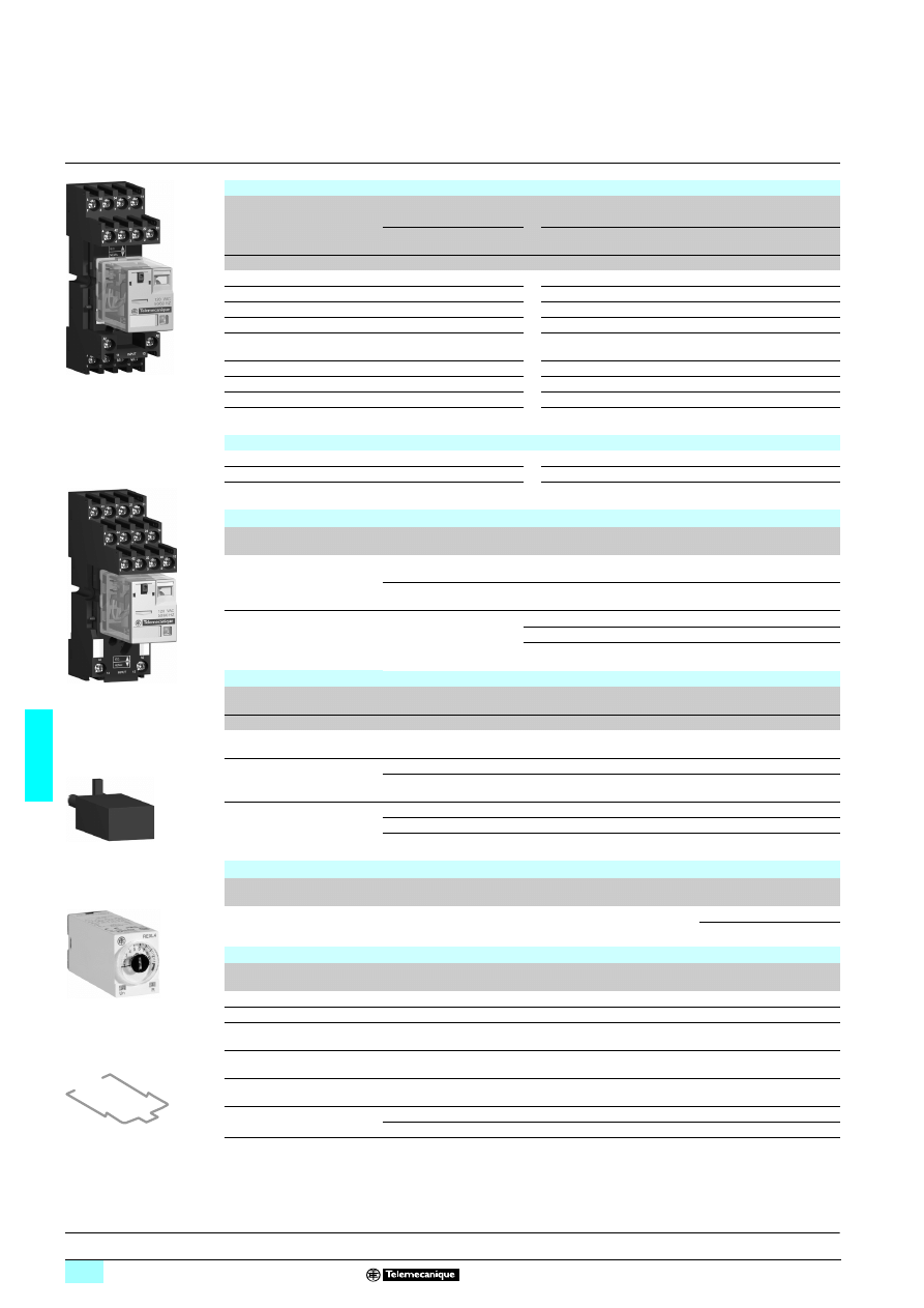
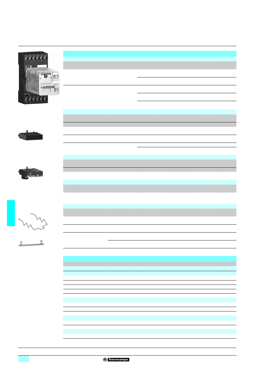
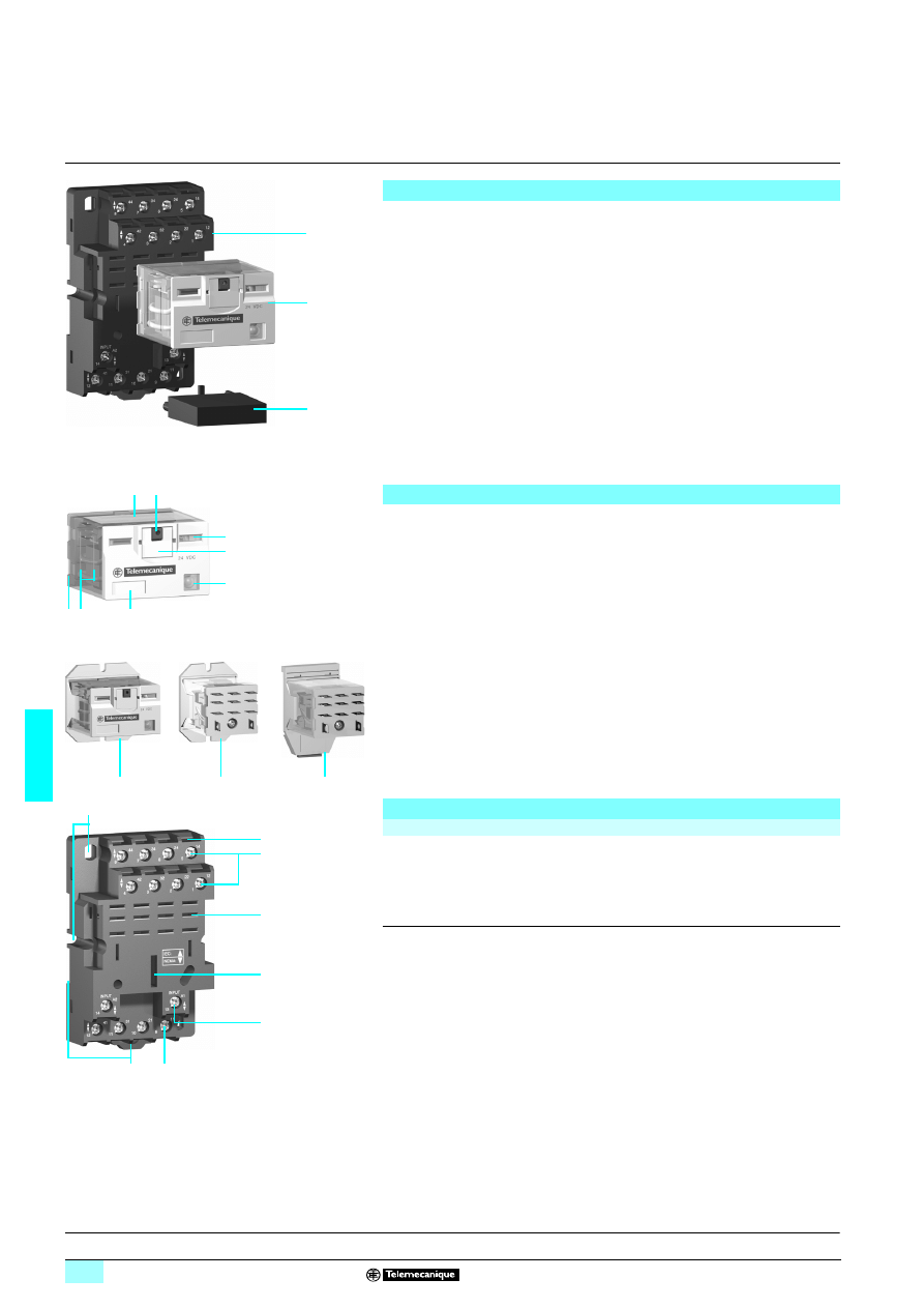
RXM miniature relays
Presentation of the range
The RXM miniature relay range comprises:
1
12 A relays with 2 C/O contacts, 10 A relays with 3 C/O contacts, 6 A relays with
4 C/O contacts and 3 A “low level” relays with 4 C/O contacts. All these relays
have the same dimensions.
2
Sockets with mixed or separate contact terminals.
3
Protection modules (diode, RC circuit or varistor). All these modules are common
to all sockets.
4
A metal maintaining clamp for all sockets.
5
A plastic maintaining clamp for all sockets.
6
A 2-pole bus jumper that can be used on sockets with separate contact terminals
in order to simplify cabling when creating an equipotential link between the coil
terminals.
7
Clip-in legends for all the sockets except RXZ E2M114.
Relay description
1
Spring return pushbutton for testing the contacts (green:
c
, red:
a
).
2
Mechanical “relay status” indicator.
3
Removable lock-down door enabling forced maintaining of the contacts for test or
maintenance purposes. During operation, this lock-down door must always be in
the closed position.
4
LED (depending on version) indicating the relay status.
5
Removable legend for relay identification.
6
Four notches for rail mounting adapter or panel mounting adapter with fixing lugs.
7
Eight, eleven or fourteen Faston type pins.
8
Area by which the product can be easily gripped.
9
Mounting adapter enabling direct mounting of the relay on a panel.
10
Mounting adapter enabling direct mounting of the relay on a 5 rail.
Socket description
Sockets with mixed contact terminals (1)
1
Connection by screw clamp terminals or connector.
2
Fourteen female contacts for the relay pins.
3
Location for protection modules.
4
Locking components for plastic and metal maintaining clamps.
5
Locating slot for mounting on 5 rail with fixing clip.
6
Two or four fixing holes for panel mounting.
Sockets with separate contact terminals (2)
1
Connection by connector.
2
Eight, eleven or fourteen female contacts for the relay pins.
3
Location for protection modules.
4
Locking components for plastic and metal maintaining clamps.
5
Locating slot for mounting on 5 rail with fixing clip.
6
Two fixing holes for panel mounting.
7
Location for bus jumpers (see mounting on sockets on page 6/14).
(1) The inputs are mixed with the relay’s supply terminals, with the outputs being located on the
opposite side of the socket.
(2) The inputs and outputs are separated from the relay supply terminals.
5
362
93
7
6
2
1
5
3
4
or
53
5189
1
2
7
3
4
5
6
8
5
3519
2
9
5
2315
1
9
5231
52
10
5351
90
1
2
3
4
5
Outputs
Inputs
Relay supply
5
6
5
3519
1
1
6
2
3
4
5 7
Outputs
Inputs
Relay supply
5
References:
pages 6/11 and 6/12
Dimensions:
pages 6/13 and 6/14
Schemes:
page 6/15
6/9
6
Characteristics
6
Zelio Relay - plug-in relays
6
RXM miniature relays
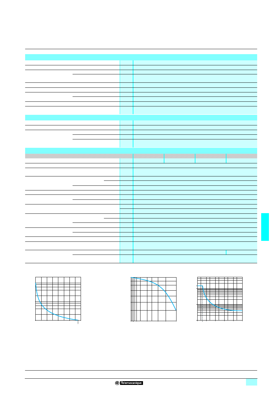
General characteristics
Conforming to standards
IEC/EN 61810-1 (iss. 2), UL 508, CSA C22-2 n° 14
Product certifications
UL, CSA
Ambient air temperature around
the device
Storage
°C
- 40… + 85
Operation
°C
- 40… + 55
Vibration resistance
Conforming to IEC/EN 60068-2-6
> 6 gn (10...50 Hz)
Degree of protection
Conforming to IEC/EN 60529
IP 40
Shock resistance
conforming to IEC/EN 60068-2-27
Opening
10 gn
Closing
5 gn
Protection category
RT I
Mounting position
Any
Insulation characteristics
Rated insulation voltage (Ui)
V
250 (IEC), 300 (UL, CSA)
Rated impulse withstand voltage (Uimp)
kV
3.6 (1.2/50
μs)
Dielectric strength
(rms voltage)
Between coil and contact
a V
2500
Between poles
a V
2500
Between contacts
a V
1500
Contact characteristics
Relay type
RXM 2ABppp
RXM 3ABppp
RXM 4ABppp
RXM 4GBppp
Number and type of contacts
2 C/O
3 C/O
4 C/O
4 C/O
Contact materials
AgNi
AgAu
Conventional thermal
current (Ith)
For ambient
temperature y 55 °C
A
12
10
6
3
Rated operational current
in utilisation categories
AC-1 and DC-1
Conforming to IEC
N/O
12
10
6
2
N/C
6
5
3
1
Conforming to UL
12
10
8
3
Maximum operating rate
In operating cycles/hour
No-load
18 000
Under load
1200
Switchable current
Minimum
mA
10
3
Switching voltage
Maximum
V
a/c 250
Minimum
V
17
Rated load (resistive)
A
12 / 250 a V
10 / 250 a V
6 / 250 a V
3 / 250 a V
A
12 / 28 c V
10 / 28 c V
6 / 28 c V
3 / 28 c V
Switching capacity
Maximum
a
VA
3000
2500
1500
750
c
W
336
280
168
84
Minimum
mW
170
15
Utilisation coefficient
20 %
Mechanical durability
In millions of operating cycles
10
Electrical durability
In millions of operating
cycles
Resistive load
0.1
Inductive load
See curves below
Electrical durability of contacts
Resistive load a
Reduction coefficient for inductive load a
(depending on power factor cos
ϕ)
Maximum switching capacity on resistive load
c
A
RXM 2ABppp
B
RXM 3ABppp
C
RXM 4ABppp
D
RXM 4GBppp
Durability (inductive load) = durability (resistive load) x reduction coefficient.
10
5
10
6
10
7
2
3
0
1
A
B
D
C
D
u
rabi
lity
(
N
umber
of op
er
ati
ng c
y
c
les
)
Switching capacity (kVA)
0,3
0,5
0,6
10,8
0,4
0,2
0,4
0,6
0,8
1
cos
ϕ
R
educ
ti
on
c
oeffi
c
ient (
A
)
0,1
1
200
250
0
50
28
100
150
10
3
6
C
D
B
A
C
u
rr
ent
c
Voltage c
References:
pages 6/11 and 6/12
Dimensions:
pages 6/13 and 6/14
Schemes:
page 6/15
6/10
6
Characteristics
(continued)
,
substitution
6
Zelio Relay - plug-in relays
6
RXM miniature relays
(1) When mounting relay RXM 2
ppppp
on socket RXZ E2M
pppp
, the thermal current must not
exceed 10 A.
(2)
d
Protection module without LED.
Coil characteristics
Average consumption
a
VA
1.2
c
W
0.9
Drop-out voltage threshold
a
u 0.15 Uc
c
u 0.1 Uc
Operating time
(response time)
Between coil energisation
and making of the
On-delay contact
a
ms
20
c
ms
20
Between coil de-energisation
and making of the
Off-delay contact
a
ms
20
c
ms
20
Control circuit voltage Uc
V
12
24
48
110
120
125
220
230
240
Relay control voltage codes
JD
BD
ED
FD
–
GD
MD
–
–
DC
Average resistance
at 20 °C ± 10%
Ω
160
650
2600
11 000
–
11 000
14 000
–
–
Operating voltage limits
Min.
V
9.6
19.2
38.4
88
–
100
176
–
–
Max.
V
13.2
26.4
52.8
121
–
138
242
–
–
Relay control voltage codes
–
B7
E7
F7
–
–
P7
U7
AC
Average resistance
at 20 °C ± 15%
Ω
–
180
770
–
4430
–
–
15 000
15 500
Operating voltage limits
Min.
V
–
19.2
38.4
–
96
–
–
184
192
Max.
V
–
26.4
52.8
–
132
–
–
253
264
Socket characteristics
Socket type
RXZ E2S108M
RXZ E2S111M RXZ E2S114M RXZ E2M114M
RXZ E2M114
Relay types used
RXM 2ppppp
RXM 3ppppp
RXM 4ppppp
RXM 2ppppp(1)
RXM 4ppppp
RXM 2ppppp(1)
RXM 4ppppp
Product certifications
UL, CSA
Conventional thermal current (Ith)
A
12
10
Degree of protection
Conforming to IEC/EN 60529
IP 20
Connection
Solid cable
without cable end
1 conductor
mm
2
0,5…2,5 mm
2
(AWG 20…AWG 14)
0,5…1,5 mm
2
(AWG 20…AWG 16)
2 conductors
mm
2
0,5…1,5 mm
2
(AWG 20…AWG 16)
0,5…0,75 mm
2
(AWG 20…AWG 18)
Flexible cable
with cable end
1 conductor
mm
2
0,2…1,5 mm
2
(AWG 24…AWG 16)
0,2…0,75 mm
2
(AWG 24…AWG 18)
2 conductors
mm
2
0,2…0,75 mm
2
(AWG 24…AWG 18)
0,2…0,5 mm
2
(AWG 24…AWG 20)
Maximum tightening torque
Nm
0.6 (M3 screw)
Contact terminal arrangement
Separate
Mixed
Bus jumper (Ith: 5 A)
Yes
No
Presentation:
page 6/8
References:
pages 6/11 and 6/12
Dimensions:
pages 6/13 and 6/14
Schemes:
page 6/15
Substitution table
Old ranges
New range
RXN
RXL
RXM
Miniature relays
RXN 21E1ppp
RXL 2A12Bppp
RXM 2ABppp
–
RXL 3A10Bppp
RXM 3ABppp
RXN 41G1ppp
RXL 4A06Bppp
RXM 4ABppp
–
RXL 4G06Bppp
RXM 4GBppp
RXN 21E1pppTQ
RXL 2A12BpppTQ
RXM 2ABpppTQ
RXN 41G1pppTQ
RXL 4A06BpppTQ
RXM 4ABpppTQ
Sockets
RXZ E1M114
RXZ E1M114
RXZ E2M114
RXZ 7G
RXZ 7G
RXZ E2M114M
RXZ E1M114M
RXZ E1M114M
RXZ E2M114M
RXZ E1p1ppM
RXZ E1p1ppM
RXZ E2p1ppM
Protection modules
RXW 040MD
RXW 040MD
RXM 040W
RZM 040W
RZM 040W
RXM 040W
RZM 031pp
RZM 031pp
RXM 040W (2)
RZM 041pp7
RZM 041pp7
RXM 041pp7
RZM 021pp
RZM 021pp
RXM 021pp (2)
Accessories
RXZ 200
RXZ 200
RXZ 400
RXZ R235
RXZ R235
RXZ R335
RXZ L320
RXZ L320
RXZ L420
6/11
6
References
6
Zelio Relay - plug-in relays
6
RXM miniature relays
Miniature relays without LED
(sold in lots of 10)
Control
circuit voltage
Number and type of contacts - Thermal current (Ith)
2 C/O -12 A
3 C/O - 10 A
4 C/O - 6 A
Unit
reference
Weight
Unit
reference
Weight
Unit
reference
Weight
V
kg
kg
kg
c 12
RXM 2AB1JD
0.037
RXM 3AB1JD
0.038
RXM 4AB1JD
0.036
c 24
RXM 2AB1BD
0.037
RXM 3AB1BD
0.038
RXM 4AB1BD
0.036
c 48
RXM 2AB1ED
0.037
RXM 3AB1ED
0.038
RXM 4AB1ED
0.036
c 110
RXM 2AB1FD
0.037
RXM 3AB1FD
0.038
RXM 4AB1FD
0.036
c 220
–
–
–
–
RXM 4AB1MD
0.036
a 24
RXM 2AB1B7
0.037
RXM 3AB1B7
0.038
RXM 4AB1B7
0.036
a 48
RXM 2AB1E7
0.037
RXM 3AB1E7
0.038
RXM 4AB1E7
0.036
a 120
RXM 2AB1F7
0.037
RXM 3AB1F7
0.038
RXM 4AB1F7
0.036
a 230
RXM 2AB1P7
0.037
RXM 3AB1P7
0.038
RXM 4AB1P7
0.036
a 240
–
–
–
–
RXM 4AB1U7
0.036
Miniature relays with LED
(sold in lots of 10)
c 12
RXM 2AB2JD
0.037
RXM 3AB2JD
0.038
RXM 4AB2JD
0.036
c 24
RXM 2AB2BD
0.037
RXM 3AB2BD
0.038
RXM 4AB2BD
0.036
c 48
RXM 2AB2ED
0.037
RXM 3AB2ED
0.038
RXM 4AB2ED
0.036
c 110
RXM 2AB2FD
0.037
RXM 3AB2FD
0.038
RXM 4AB2FD
0.036
c 125
–
–
–
–
RXM 4AB2GD
0.036
a 24
RXM 2AB2B7
0.037
RXM 3AB2B7
0.038
RXM 4AB2B7
0.036
a 48
RXM 2AB2E7
0.037
RXM 3AB2E7
0.038
RXM 4AB2E7
0.036
a 120
RXM 2AB2F7
0.037
RXM 3AB2F7
0.038
RXM 4AB2F7
0.036
a 230
RXM 2AB2P7
0.037
RXM 3AB2P7
0.038
RXM 4AB2P7
0.036
Miniature relays with low level contacts, without LED
(sold in lots of 10)
Control
circuit voltage
Number and type of contacts
Thermal current (Ith)
4 C/O - 3 A
Unit
reference
Weight
V
kg
c 12
RXM 4GB1JD
0.036
c 24
RXM 4GB1BD
0.036
c 48
RXM 4GB1ED
0.036
c 110
RXM 4GB1FD
0.036
a 24
RXM 4GB1B7
0.036
a 48
RXM 4GB1E7
0.036
a 120
RXM 4GB1F7
0.036
a 230
RXM 4GB1P7
0.036
Miniature relays with low level contacts, with LED
(sold in lots of 10)
c 12
RXM 4GB2JD
0.036
c 24
RXM 4GB2BD
0.036
c 48
RXM 4GB2ED
0.036
c 110
RXM 4GB2FD
0.036
a 24
RXM 4GB2B7
0.036
a 48
RXM 4GB2E7
0.036
a 120
RXM 4GB2F7
0.036
a 230
RXM 4GB2P7
0.036
a 240
RXM 4GB2U7
0.036
RXM
p
AB2F7
53
5189
RXM 4GB2F7
535
189
Presentation:
page 6/8
Characteristics:
pages 6/9 and 6/10
Dimensions:
pages 6/13 and 6/14
Schemes:
page 6/15
6/12
6
References
(continued)
6
Zelio Relay - plug-in relays
6
RXM miniature relays
Miniature relays without LED
(sold in lots of 100)
Control
circuit voltage
Number and type of contacts - Thermal current (Ith)
2 C/O - 12 A
4 C/O - 6 A
Unit
reference
Weight
Unit
reference
Weight
V
kg
kg
c 12
–
–
RXM 4AB1JDTQ
0.036
c 24
RXM 2AB1BDTQ
0.037
RXM 4AB1BDTQ
0.036
c 48
–
–
RXM 4AB1EDTQ
0.036
c 110
–
–
RXM 4AB1FDTQ
0.036
c 220
–
–
RXM 4AB1MDTQ
0.036
a 24
RXM 2AB1B7TQ
0.037
RXM 4AB1B7TQ
0.036
a 48
–
–
RXM 4AB1E7TQ
0.036
a 120
RXM 2AB1F7TQ
0.037
RXM 4AB1F7TQ
0.036
a 230
RXM 2AB1P7TQ
0.037
RXM 4AB1P7TQ
0.036
Miniature relays with LED
(sold in lots of 100)
c 24
–
–
RXM 4AB2BDTQ
0.036
a 24
RXM 2AB2B7TQ
0.037
RXM 4AB2B7TQ
0.036
a 230
RXM 2AB2P7TQ
0.037
RXM 4AB2P7TQ
0.036
Sockets
Contact terminal
arrangement
Connection
Relay type
Sold in
lots of
Unit
reference
Weight
kg
Mixed
Screw clamp terminals
RXM 2pppp(3)
RXM 4pppp
10
RXZ E2M114 (1)
0.048
Connector
RXM 2pppp(3)
RXM 4pppp
10
RXZ E2M114M (1)
0.056
Separate
Connector
RXM 2pppp
10
RXZ E2S108M (2)
0.058
RXM 3pppp
10
RXZ E2S111M (1)
0.066
RXM 4pppp
10
RXZ E2S114M (1)
0.070
Protection modules
Description
Voltage
For
use with
Sold in
lots of
Unit
reference
Weight
V
kg
Diode
c 6...250
All sockets
20
RXM 040W
0.003
RC circuit
a 24...60
All sockets
20
RXM 041BN7
0.010
a 110...240
All sockets
20
RXM 041FU7
0.010
Varistor
a/c 6...24
All sockets
20
RXM 021RB
0.030
a/c 24...60
All sockets
20
RXM 021BN
0.030
a/c 110...240
All sockets
20
RXM 021FP
0.030
Timing relays
Description
For
use with
Unit
reference
Weight
kg
2 or 4 timed C/O contacts
(function A)
Sockets RXZ Eppppp
RE XL2pp (4)
–
RE XL4pp (4)
–
Accessories
Description
For
use with
Sold in
lots of
Unit
reference
Weight
kg
Metal maintaining clamp
All sockets
10
RXZ 400
0.001
Plastic maintaining clamp
All sockets
10
RXZ R335
0.005
Bus jumper, 2-pole
(Ith: 5 A)
All sockets with separate contacts
10
RXZ S2
0.005
Mounting adapter
for 5 rails (5)
All relays
10
RXZ E2DA
0.004
Mounting adapter
with fixing lugs for panel
All relays
10
RXZ E2FA
0.002
Clip-in legends
All relays (sheet of 108 legends)
10
RXZ L520
0.080
All sockets except RXZ E2M114
10
RXZ L420
0.001
(1) Thermal current Ith: 10 A
(2) Thermal current Ith: 12 A
(3) When mounting relay RXM 2
ppppp
on socket RXZ E2M
pppp
, the thermal current must not exceed 10 A.
(4) Please consult the "Zelio Time timing relays" catalogue.
(5) Test button becomes inaccessible.
RXZ E2M114M
+
Relay RXM 4AB2P7TQ
53
5235
535
211
RXZ E2S114M
+
Relay RXM 4AB2F7
5352
12
RXM 041
pp
7
53
5195
RE XL4
pp
53
6484
RXZ 400
Presentation:
page 6/8
Characteristics:
pages 6/9 and 6/10
Dimensions:
pages 6/13 and 6/14
Schemes:
page 6/15
6/13
6
Dimensions
6
Zelio Relay - plug-in relays
6
RXM miniature relays
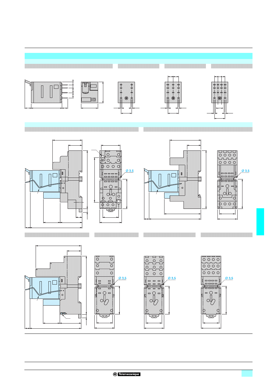
Dimensions
Miniature relays
RXM pppppp
RXM 2
RXM 3
RXM 4
Common view
Pin side view
Sockets
RXZ E2M114
RXZ E2M114M
Common side view
RXZ E2S108M
RXZ E2S111M
RXZ E2S114M
(1) Relays
(2) Add-on protection module
(3) Maintaining clamp
(4) 2 elongated holes Ø 3.5 x 6.5
(5) 2 bus jumpers
40
21
27
7
6
2,5
2,5
21
6,5
6
4
4
13,5
2,5
2,5
4,5
21
13,5
=
=
2,5
2,5
13,5
=
=
=
(1)
(2)
(3)
25,5
34
7
A2
14
A1
13
24
6
44
8
14
5
12
1
11
9
21
10
31
11
41
12
22
2
32
3
42
4
(4)
19
40
30
9
23
21
30
69
7
39,5
61
3,5
79
17
43
23,5
50
27
67
7
40
80
44
8
34
7
24
6
14
5
42
4
32
3
22
2
12
1
A1
13
A2
14
41
12
31
11
21
10
11
9
(3)
(1)
(2)
19
61
29
23
70
7
3,5
79
(3)
(2)
(1)
(5)
23,5
27
38
41
12
11
9
44
8
14
5
A1
13
A2
14
42
4
12
1
23,5
27
38
31
9
34
6
A1
13
A2
14
32
3
21
8
24
5
22
2
11
7
14
4
12
1
23,5
27
38
41
12
31
11
21
10
11
9
44
8
34
7
24
6
14
5
42
4
32
3
22
2
12
1
A1
13
A2
14
Presentation:
page 6/8
Characteristics:
pages 6/9 and 6/10
References:
pages 6/11 and 6/12
Schemes:
page 6/15
6/14
6
Dimensions
(continued)
6
Zelio Relay - plug-in relays
6
RXM miniature relays
Dimensions
(continued)
Plastic clamp and clip-in legends
RXZ R335
RXZ L420
Mounting on all sockets (1)
(1) Clip-in legends for all sockets except
RXZ E2M114.
Bus jumper
Metal clamp
RXZ S2
Mounting on sockets with separate contacts
(view from below)
RXZ 400
Example of bus jumper mounting on sockets
(1) 2 bus jumpers (polarity A2)
(2) 2 bus jumpers (polarity A1)
Mounting adapter for rail (1)
Mounting adapter for panel
RXZ E2DA
RXZ E2FA
(1) Test button becomes inaccessible
57
27
12
14,2
26,5
81
94,5
(1)
2,2
7,3
25
22
2,3
(1)
(1)
(2)
(2)
22
42
0,8
38
6
4
24
34
8
23
51
48
49
3,5
43
38
4
24
3,5
Presentation:
page 6/8
Characteristics:
pages 6/9 and 6/10
References:
pages 6/11 and 6/12
6/15
6
Schemes
6
Zelio Relay - plug-in relays
6
RXM miniature relays
Schemes
Miniature relays
RXM 2ppppp
RXM 3ppppp
RXM 4ppppp
Symbols shown in blue correspond to Nema marking.
A2
A1
41
44
42
11
14
12
1
12
5
14
9
11
4
42
8
44
12
41
13
A1
14
A2
A2
A1
31
34
32
21
24
22
11
14
12
1
12
4
14
7
11
2
22
5
24
8
21
3
32
6
34
9
31
13
A1
14
A2
A2
A1
41
44
42
21
24
22
31
34
32
11
14
12
1
12
5
14
9
11
4
42
8
44
12
41
2
22
6
24
10
21
3
32
7
34
11
31
13
A1
14
A2
Presentation:
page 6/8
Characteristics:
pages 6/9 and 6/10
References:
pages 6/11 and 6/12
6/16
6
Presentation
6
Zelio Relay - plug-in relays
6
RUM universal relays
Presentation of the range
The RUM universal relay range comprises:
1
10 A relays with 2 and 3 C/O contacts, with cylindrical or flat (Faston type) pins,
and 3 A “low level” relays with 3 C/O contacts, with cylindrical pins. All these relays
have the same dimensions.
2
Sockets with mixed or separate contact terminals.
3
Protection modules (diode, RC circuit or varistor) or 1 timer module. All these
modules are common to all sockets.
4
A metal maintaining clamp for all sockets.
5
A 2-pole bus jumper that can be used on sockets with separate contact terminals
in order to simplify cabling when creating an equipotential link between the coil
terminals.
6
Clip-in legends for the sockets.
Relay description
1
Spring return pushbutton for testing the contacts (green:
c
, red:
a
).
2
Mechanical “relay status” indicator.
3
Removable lock-down door enabling forced maintaining of the contacts for test or
maintenance purposes. During operation, this lock-down door must always be in
the closed position.
4
LED (depending on version) indicating the relay status.
5
Removable legend for relay identification.
6
Eight or eleven cylindrical or flat (Faston type) pins.
7
Area by which the product can be easily gripped.
Socket description
Sockets with mixed contact terminals (1)
1
Connection by connector.
2
Eight or eleven female contacts for the relay cylindrical pins.
3
Location for protection modules or the timer module.
4
Locking component for metal maintaining clamp.
5
Locating slot for 5 rail mounting.
6
Two fixing holes for panel mounting.
Sockets with separate contact terminals (2)
1
Connection by connector.
2 a
Eight or eleven female contacts for the relay cylindrical pins.
b
Eleven female contacts for the relay flat pins.
3
Location for protection modules or the timer module.
4
Locking component for metal maintaining clamp.
5
Locating slot for mounting on 5 rail with fixing clip.
6
Two fixing holes for panel mounting.
7
Location for bus jumpers (see mounting on sockets on page 6/22).
(1) The inputs are mixed with the relay’s supply terminals, with the outputs being located on the
opposite side of the socket.
(2) The inputs and outputs are separated from the relay supply terminals.
5
362
94
6
5
2
1
3
4
5
351
96
1
2
6
3
4
5
7
53
5218
1
2
3
4
5
6
Outputs
Relay supply
Inputs
Relay supply
5351
97
1
6
2a
3
4
5 7
Inputs
Outputs
Relay supply
5
5351
98
1
2b
3
4
5 7
Inputs
Outputs
Relay supply
5
References:
pages 6/19 and 6/20
Dimensions:
pages 6/21 and 6/22
Schemes:
page 6/22
6/17
6
Characteristics
6
Zelio Relay - plug-in relays
6
RUM universal relays
General characteristics
Conforming to standards
IEC/EN 61810-1 (iss. 2), UL 508, CSA C22-2 n° 14
Product certifications
UL, CSA
Ambient air temperature
around the device
Storage
°C
- 40… + 85
Operation
°C
- 40… + 55
Vibration resistance
Conforming to IEC/EN 60068-2-6
4 gn (10...50 Hz)
Degree of protection
Conforming to IEC/EN 60529
IP 40
Shock resistance
conforming to IEC/EN 60068-2-27
Opening
10 gn
Closing
5 gn
Protection category
RT I
Mounting position
Any
Insulation characteristics
Rated insulation voltage (Ui)
Conforming to IEC/EN 60947
V
250 (IEC), 300 (UL, CSA)
Rated impulse withstand voltage (Ump)
kV
3.6 (1.2/50
μs)
Dielectric strength
(rms voltage)
Between coil and contact
a V
2500
Between poles
a V
2500
Between contacts
a V
1500
Contact characteristics
Relay type
RUM F2ppp
RUM F3ppp
RUM C2ppp
RUM C3App
RUM C3Gpp
Number and type of contacts
2 C/O
3 C/O
2 C/O
3 C/O
3 C/O
Contact materials
.
AgNi
AgAu
Conventional thermal
current (Ith)
For ambient
temperature y 55°C
A
10
3
Rated operational current
in utilisation categories
AC-1 and DC-1
Conforming to IEC
N/O
A
10
2
N/C
A
5
1
Conforming to UL
A
16 / a 277 V
12 / c 28 V
3
Switchable current
Minimum
mA
10
3
Switching voltage
Maximal
V
a/c 250 (IEC)
Minimal
V
17
5
Rated load (resistive)
A
10 / 250 a V
3 / 250 a V
A
10 / 28 c V
3 / 28 c V
Switching capacity
Maximal
a
VA
2500
750
c
W
280
84
Minimal
mW
170
15
Maximum operating rate
In operating cycles/hour
No-load
36 000
Under load
3600
Utilisation coefficient
20 %
Mechanical durability
In millions of operating cycles
5
Electrical durability
In millions of operating
cycles
Resistive load
0.1
Inductive load
See curves below
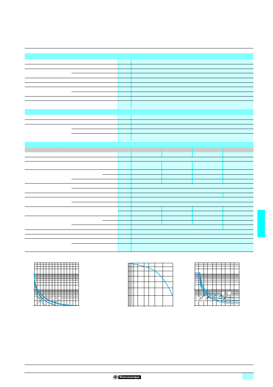
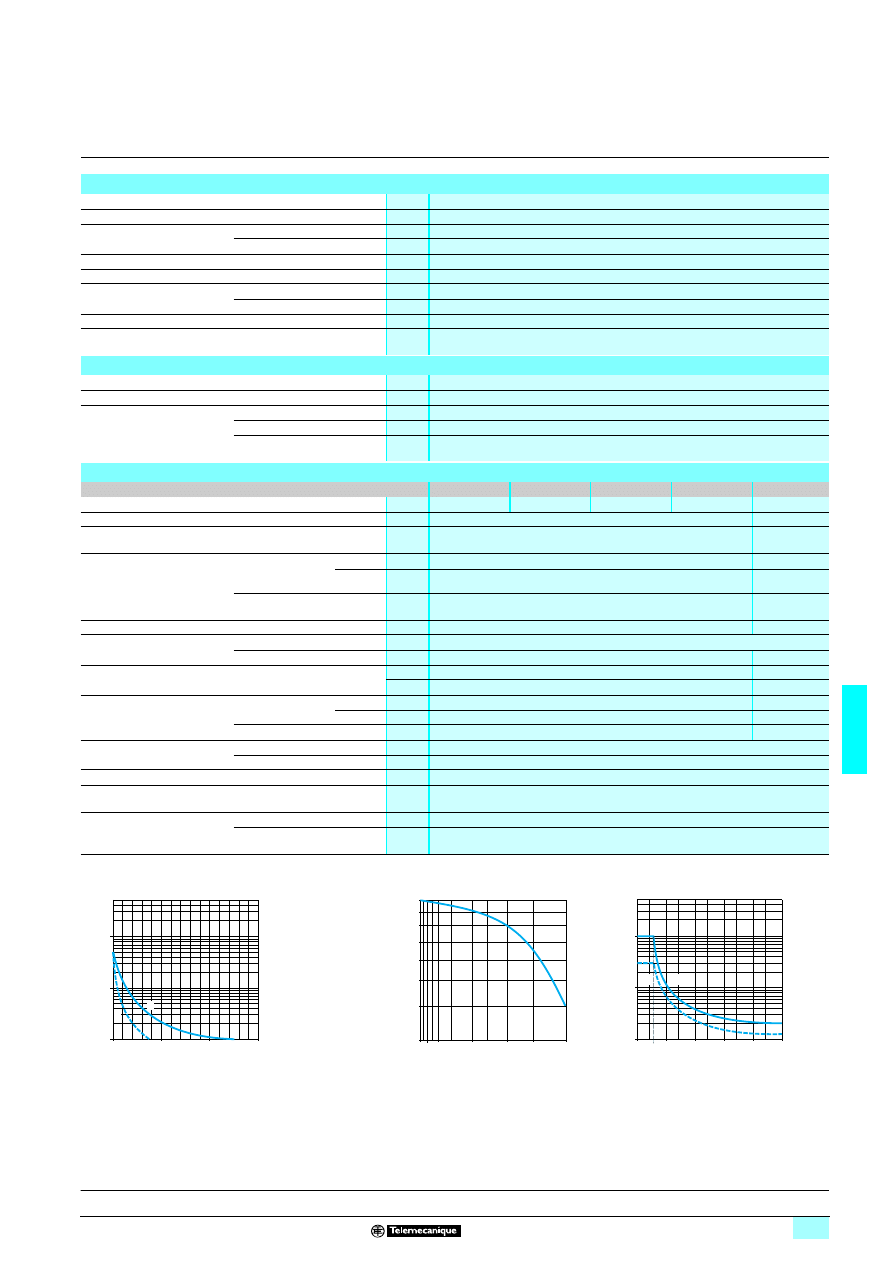
Electrical durability of contacts
Resistive load a
Reduction coefficient for inductive load a
(depending on power factor cos
ϕ)
Maximum switching capacity on resistive load
c
A
RUM Fppppp, RUM C2ppp, RUM C3Appp
B
RUM C3Gppp
Durability (inductive load) = durability (resistive load) x reduction coefficient.
10
5
10
6
10
7
2
3
0
1
A
B
D
u
ra
bi
lity
(
N
um
ber
of oper
ati
n
g
c
y
c
les
)
Switching capacity (kVA)
0,3
0,5
0,6
10,8
0,4
0,2
0,4
0,6
0,8
1
cos
ϕ
R
e
duc
ti
on c
oeffi
c
ient
(
A
)
0,1
1
200
250
0
50
100
150
10
3
B
A
28
C
u
rr
ent
c
Voltage c
References:
pages 6/19 and 6/20
Dimensions:
pages 6/21 and 6/22
Schemes:
page 6/22
6/18
6
Characteristics
(continued)
6
Zelio Relay - plug-in relays
6
RUM universal relays
Coil characteristics
Average consumption
a
VA
2...3
c
W
1.4
Drop-out voltage threshold
a
u 0.15 Uc
c
u 0.1 Uc
Operating time
(response time)
Between coil
energisation and
making of the
On-delay contact
a
ms
20
c
ms
20
Between coil
de-energisation
and making of the
Off-delay contact
a
ms
20
c
ms
20
Control circuit voltage Uc
V
12
24
48
60
110
120
125
220
230
Relay control voltage codes
JD
BD
ED
ND
FD
–
GD
MD
–
DC
Average resistance
at 20 °C ± 10%
Ω
120
470
1800
2790
10 000
–
10 000
3700
–
Operating voltage
limits
Min.
V
9.6
19.2
38.4
48
88
–
100
176
–
Max.
V
13.2
26.4
52.8
66
121
–
137.5
242
–
Relay control voltage codes
–
B7
E7
–
–
F7
–
–
P7
AC
Average resistance
at 20 °C ± 15%
Ω
–
72
290
–
–
1700
–
–
7200
Operating voltage
limits
Min.
V
–
19.2
38.4
–
–
96
–
–
184
Max.
V
–
26.4
52.8
–
–
132
–
–
253
Socket characteristics
Socket type
RUZ C2M
RUZ C3M
RUZ SC2M
RUZ SC3M
RUZ SF3M
Relay types used
RUM C2ppppp
RUM C3ppppp
RUM C2ppppp
RUM C3ppppp
RUM Fppppp
Product certifications
UL, CSA
Conventional thermal current (Ith)
A
12
Degree of protection
Conforming to IEC/EN 60529
IP 20
Connection
Solid cable without cable end
mm
2
1 conductor: 0.5…2.5 mm
2
(AWG 20…AWG 14)
2 conductors: 0.5…1.5 mm
2
(AWG 20…AWG 16)
Flexible cable with cable end
mm
2
1 conductor: 0.2…1.5 mm
2
(AWG 24…AWG 16)
2 conductors: 0.2…0,75 mm
2
(AWG 24…AWG 18)
Maximum tightening torque
Nm
0.6 (M3 screw)
Contact terminal arrangement
Mixed
Separate
Bus jumper
Ith: 5 A
No
Yes
Presentation:
page 6/16
References:
pages 6/19 and 6/20
Dimensions:
pages 6/21 and 6/22
Schemes:
page 6/22
6/19
6
References
6
Zelio Relay - plug-in relays
6
RUM universal relays
References
Relays for standard applications, without LED
(sold in lots of 10)
Pins
Control
circuit voltage
Number and type of contacts - Thermal current (Ith)
2 C/O -10 A
3 C/O -10 A
Unit
reference
Weight
Unit
reference
Weight
V
kg
kg
Cylindrical
c 12
RUM C2AB1JD
0.084
RUM C3AB1JD
0.088
c 24
RUM C2AB1BD
0.084
RUM C3AB1BD
0.088
c 48
RUM C2AB1ED
0.084
RUM C3AB1ED
0.088
c 60
–
–
RUM C3AB1ND
0.088
c 110
RUM C2AB1FD
0.084
RUM C3AB1FD
0.088
c 125
–
–
RUM C3AB1GD
0.088
c 220
–
–
RUM C3AB1MD
0.088
a 24
RUM C2AB1B7
0.084
RUM C3AB1B7
0.088
a 48
RUM C2AB1E7
0.084
RUM C3AB1E7
0.088
a 120
RUM C2AB1F7
0.084
RUM C3AB1F7
0.088
a 230
RUM C2AB1P7
0.084
RUM C3AB1P7
0.088
Flat (Faston type)
c 12
RUM F2AB1JD
0.080
RUM F3AB1JD
0.084
c 24
RUM F2AB1BD
0.080
RUM F3AB1BD
0.084
c 48
RUM F2AB1ED
0.080
RUM F3AB1ED
0.084
c 110
RUM F2AB1FD
0.080
RUM F3AB1FD
0.084
a 24
RUM F2AB1B7
0.080
RUM F3AB1B7
0.084
a 48
RUM F2AB1E7
0.080
RUM F3AB1E7
0.084
a 120
RUM F2AB1F7
0.080
RUM F3AB1F7
0.084
a 230
RUM F2AB1P7
0.080
RUM F3AB1P7
0.084
Relays for standard applications, with LED
(sold in lots of 10)
Cylindrical
c 12
RUM C2AB2JD
0.084
RUM C3AB2JD
0.088
c 24
RUM C2AB2BD
0.084
RUM C3AB2BD
0.088
c 48
RUM C2AB2ED
0.084
RUM C3AB2ED
0.088
c 60
–
–
RUM C3AB2ND
0.088
c 110
RUM C2AB2FD
0.084
RUM C3AB2FD
0.088
c 125
–
–
RUM C3AB2GD
0.088
a 24
RUM C2AB2B7
0.084
RUM C3AB2B7
0.088
a 48
RUM C2AB2E7
0.084
RUM C3AB2E7
0.088
a 120
RUM C2AB2F7
0.084
RUM C3AB2F7
0.088
a 230
RUM C2AB2P7
0.084
RUM C3AB2P7
0.088
Flat (Faston type)
c 12
RUM F2AB2JD
0.084
RUM F3AB2JD
0.086
c 24
RUM F2AB2BD
0.084
RUM F3AB2BD
0.086
c 48
RUM F2AB2ED
0.084
RUM F3AB2ED
0.086
c 110
RUM F2AB2FD
0.084
RUM F3AB2FD
0.086
a 24
RUM F2AB2B7
0.084
RUM F3AB2B7
0.086
a 48
RUM F2AB2E7
0.084
RUM F3AB2E7
0.086
a 120
RUM F2AB2F7
0.084
RUM F3AB2F7
0.086
a 230
RUM F2AB2P7
0.084
RUM F3AB2P7
0.086
Relays with low level contacts, with LED
(sold in lots of 10)
Pins
Control
circuit voltage
Number and type of contacts
Thermal current (Ith)
3 C/O - 3 A
Unit
reference
Weight
V
kg
Cylindrical
c 24
RUM C3GB2BD
0.086
c 48
RUM C3GB2ED
0.086
a 24
RUM C3GB2B7
0.086
a 48
RUM C3GB2E7
0.086
a 120
RUM C3GB2F7
0.086
a 230
RUM C3GB2P7
0.086
RUM
pp
AB2B7
53
5199
RUM
pp
AB2F7
53
520
0
Presentation:
page 6/16
Characteristics:
pages 6/17 and 6/18
Dimensions:
pages 6/21 and 6/22
Schemes:
page 6/22
6/20
6
References
(continued)
,
substitution table
6
Zelio Relay - plug-in relays
6
RUM universal relays
References
(continued)
Sockets
Contact terminal
arrangement
Connection
Relay type
Sold in
lots of
Unit
reference
Weight
kg
Mixed
Connector
RUM C2ppppp
10
RUZ C2M
0.054
RUM C3ppppp
10
RUZ C3M
0.054
Separate
Connector
RUM C2ppppp
10
RUZ SC2M
0.095
RUM C3ppppp
10
RUZ SC3M
0.100
RUM F2pppp
10
RUZ SF3M
0.095
RUM F3pppp
Protection modules
Description
For
use with
Voltage
Sold in
lots of
Unit
reference
Weight
V
kg
Diode
All sockets
c 6…250
10
RUW 240BD
0.004
RC circuit
All sockets
a 110…240
10
RUW 241P7
0.004
Varistor
All sockets
a/c 24
10
RUW 242B7
0.004
a/c 240
10
RUW 242P7
0.004
Timer module
Description
For
use with
Voltage
Reference
Weight
V
kg
Multifunction
All sockets
a/c 24…240
RUW 101MW
0.020
Timing relays
Description
For
use with
Reference
Weight
kg
2 timed C/O contacts
(single-function or multifunction)
On sockets RUZ CpM
RE 48A pp (1)
–
Accessories
Description
For
use with
Sold in
lots of
Unit
reference
Weight
kg
Metal maintaining clamp
All sockets
10
RUZ C200
0.001
Bus jumper, 2-pole
(Ith : 5 A)
All sockets with separate contacts
10
RUZ S2
0.005
Clip-in legends
All relays
(sheet of 108 legends)
10
RXZ L520
0.080
All sockets with separate contacts
10
RUZ L420
0.001
(1) Please consult the "Zelio Time timing relays" catalogue.
Substitution table
Old range
New range
RUN
RUM
Universal relays
RUN 21C2ppp
RUM F2ABppp
RUN 31C2ppp
RUM F3ABppp
RUN 21D2ppp
RUM C2ABppp
RUN 31A2ppp
RUM C3ABppp
RUN 33A22pp
RUM C3GB2pp
Sockets
RUZ pA
RUZ C3M
RUZ pD
RUZ C2M
RUZ 1C
RUZ SF3M
Protection modules
RUW 030BD
RUW 240BD (2)
RUW 04ppp
RUW 24ppp (2)
Accessories
RUZ 2p0
RUZ C200
(2)
d
Protection module without DEL.
53
5199
RUZ C3M + relay
RUM C3
ppppp
RUW 241P7
53
5202
RUW 101MW
535
219
RUZ C200
536
485
RUZ S2
53
5203
Presentation:
page 6/16
Characteristics:
pages 6/17 and 6/18
Dimensions:
pages 6/21 and 6/22
Schemes:
page 6/22
6/21
6
Dimensions
6
Zelio Relay - plug-in relays
6
RUM universal relays
Dimensions
Universal relays
RUM Cpp
RUM Fpp
Sockets
Common side view
RUZ C2M
RUZ C3M
RUZ SC2M
RUZ SC3M
(1) Relay
(2) Protection module
(3) Maintaining clamp
(4) 2 bus jumpers
55
34
34
6
34
34
53
6
75
27
22
63
89
93
(1)
(3)
(2)
38
37
30
24
6
2
7
A2
7
A1
2
11
1
21
8
A2
7
INPUT A2
INPUT A1
22
5
12
4
1
4
2
3
8
5
7
6
14
3
2xØ3,1
38
37
30
A2
10
A2
10
31
11
21
6
11
1
A1
2
34
9
32
8
24
7
22
5
14
3
12
4
2
10
1
6
2
5
3
4
11
10
7
9
8
INPUT A2
INPUT A1
2xØ3,1
36
75
102
105
29
92
4
40
30
19
45
22
5
11
1
12
4
24
6
1
4
2
3
8
5
7
6
A2
7
A1
2
21
8
14
3
Ø 4
(4)
(1)
(3)
(2)
36
75
102
105
29
92
4
40
32
63
31
11
21
6
11
1
32
8
22
5
12
4
34
9
2
1
5
3
4
11
7 6
10
9
8
A2
10
A1
2
24
7
14
3
Ø 4
(1)
(3)
(2)
19
(4)
Presentation:
page 6/16
Characteristics:
pages 6/17 and 6/18
References:
pages 6/19 and 6/20
Schemes:
page 6/22
6/22
6
Dimensions
(continued)
schemes
6
Zelio Relay - plug-in relays
6
RUM universal relays
Dimensions
(continued)
Sockets
(continued)
RUZ SF3M
(1) Relay
(2) Protection module
(3) Maintaining clamp
(4) 2 bus jumpers
Metal maintaining clamps and plastic legends
Bus jumper
RUZ C200
Mounting
RUZ S2
Mounting on sockets with separate contacts
(view from below)
Example of bus jumper mounting on sockets
RUZ L420
(1) 2 bus jumpers (polarity A2)
(2) 2 bus jumpers (polarity A1)
Schemes
Universal relays
RUM p2ABppp
RUM C3ppppp
RUM F3ABppp
RUM C2ABppp
RUM F2ABppp
RUM C3ppppp
RUM F3ABppp
Symbols shown in blue correspond to Nema marking.
36
104
29
46
27
92
4
63
21
9
31
8
11
7
22
3
32
2
12
1
24
6
A2
B
A1
A
34
5
14
4
(1)
(3)
(2)
(4)
0,8
59,6
35
108
3,3
8,5
35,4
32
2,3
(2)
(2)
(1)
(1)
12
14,2
32
12
11
14
22
21
24
A2
A1
12
11
14
22
21
24
32
31
34
A2
A1
12
11
14
22
21
24
32
31
34
A2
A1
3
7
1
8
6
2
4
5
A1
A2
21
11
14
24
22
12
+
1
12
4
14
7
11
3
22
6
24
9
21
A
A1
B
A2
(+)
( )
4
3
9
2
1
11
10
8
5
6
7
A1
A2
14
34
31
11
12
32
22
24
21
+
(+)
1
12
4
14
7
11
2
32
5
34
8
31
3
22
6
24
9
21
A
A1
B
A2
( )
Presentation:
page 6/16
Characteristics:
pages 6/17 and 6/18
References:
pages 6/19 and 6/20
6/23
6
Setting-up
6
Zelio Relay - plug-in relays
6
RUM universal relays
Multifunction timer module RUW 101MW
Programming
Timing range selection
Function selection
Selection
Function
Control
Function diagram
Control scheme
On-delay timer
E
Series control
Monostable with
maintained control
Wu
Series control
Flashing relay,
starting On-delay phase
Bi
Series control
Flashing relay,
starting Off-delay phase
Bp
Series control
Off-delay timer
R
Control by external contact
(S)
Monostable
with pulse control
Ws
Control by external contact
(S)
Monostable, starting
on de-energisation
Wa
Control by external contact
(S)
On-delay timer
Es
Control by external contact
(S)
Power off
Contact open
U: voltage
S: external control
Power on
Contact closed
R: relay RUM ppp
t: adjustable time delay
Function
selection
Timing range
selection
0.1…1 s
0.1…10 s
0.1…1 min
1…10 min
0.1…1 h
1…10 h
0.1…1 day
1…10 days
t
U
.1/.4
.1/.2
A1
A2
U
R
U
.1/.4
.1/.2
t
U
.1/.4
.1/.2
t t
U
.1/.4
.1/.2
t t
S
U
.1/.4
.1/.2
t
B1
A1
A2
U
R
S
S
U
.1/.4
.1/.2
t
S
U
.1/.4
.1/.2
t
S
U
.1/.4
.1/.2
t
Presentation:
page 6/16
Characteristics:
pages 6/17 and 6/18
References:
pages 6/19 and 6/20
Dimensions:
pages 6/21 and 6/22
6/24
6
Presentation
6
Zelio Relay - plug-in relays
6
RPM power relays
Presentation of the range
The RPM power relay range comprises:
1
15 A relays with 1, 2, 3 and 4 C/O contacts.
2
Sockets with mixed contact terminals.
3
Protection modules (diode, RC circuit or varistor) or 1 timer module. All these
modules are common to all the sockets except for the timer module, which can
only be used on the 3-pole or 4-pole sockets.
A metal maintaining clamp for 1 contact relays.
Relay description
1
Spring return pushbutton for testing the contacts (green: c, red: a).
2
Mechanical “relay status” indicator.
3
Removable lock-down door enabling forced maintaining of the contacts for test or
maintenance purposes. During operation, this lock-down door must always be in
the closed position.
4
LED (depending on version) indicating the relay status.
5
Removable legend for relay identification.
6
Four notches for rail mounting adapter or panel mounting adapter with fixing lugs.
7
Five, eight, eleven or fourteen Faston type pins.
8
Area by which the product can be easily gripped.
9
Mounting adapter enabling direct mounting of the relay on a panel.
10
Mounting adapter enabling direct mounting of the relay on a 5 rail.
Socket description
Sockets with mixed contact terminals (1)
1
Connection by screw clamp terminals.
2
Five, eight, eleven or fourteen female contacts for the relay pins.
3
Location for protection modules or the timer module.
4
Locating slot for mounting on 5 rail with fixing clip.
5
Two or four fixing holes for panel mounting.
(1) The inputs are mixed with the relay’s supply terminals, with the outputs being located on the
opposite side of the socket.
5
231
44
2
1
3
5231
45
2
7
3
5
6
8
4
1
5
231
56
9
5
231
57
9
5
231
58
10
5
2314
6
1
5
2
3
Outputs
4
Inputs
Supply
relay
References:
pages 6/27 and 6/28
Dimensions:
pages 6/29 and 6/30
Schemes:
page 6/31
6/25
6
Characteristics
6
Zelio Relay - plug-in relays
6
RPM power relays
General characteristics
Conforming to standards
IEC/EN 61810-1 (iss. 2), UL 508, CSA C22-2 n° 14
Product certifications
UL, CSA
Ambient air temperature
around the device
Storage
°C
- 40… + 85
Operation
°C
- 40… + 55
Vibration resistance
Conforming to IEC/EN 60068-2-6
6 gn (10...50 Hz)
Degree of protection
Conforming to IEC/EN 60529
IP 40
Shock resistance
conforming to IEC/EN 60068-2-27
Opening
10 gn
Closing
10 gn
Protection category
RT I
Mounting position
Any
Insulation characteristics
Rated insulation voltage (Ui)
Conforming to IEC/EN 60947
V
250 (IEC), 300 (UL, CSA)
Rated impulse withstand voltage (Uimp)
kV
3.6 (1.2/50
μs)
Dielectric strength
(rms voltage)
Between coil and contact
a V
2500
Between poles
a V
2500
Between contacts
a V
1500
Contact characteristics
Relay type
RPM 1ppp
RPM 2ppp
RPM 3ppp
RPM 4ppp
Number and type of contacts
1 C/O
2 C/O
3 C/O
4 C/O
Contact materials
AgNi
Conventional thermal current
(Ith)
For ambient
temperature y 55 °C
A
15
Rated operational current
in utilisation categories
AC-1 and DC-1
Conforming to IEC
N/O
A
15
N/C
A
7.5
Conforming to UL
A
15
Switchable current
Minimum
mA
10
Switching voltage
Maximum
V
a/c 250 (IEC)
Minimum
V
17
Rated load (resistive)
A
15 / 250 a V
A
15 / 28 c V
Switching capacity
Maximum
a
VA
3750
c
W
420
Minimum
mW
170
Maximum operating rate
In operating cycles/hour
No-load
18 000
Under load
1200
Utilisation coefficient
20 %
Mechanical durability
In millions of
operating cycles
10
Electrical durability
In millions of operating
cycles
Resistive load
0.1
0.06
Inductive load
See curves below
Electrical durability of contacts
Resistive load a
Reduction coefficient for inductive load a
(depending on power factor cos
ϕ)
Maximum switching capacity on resistive load
c
Durability (inductive load) = durability (resistive load) x reduction coefficient.
105
2
0
1
4
3
3,75
106
107
D
u
ra
bi
lity
(
N
um
ber
of oper
ati
n
g
c
y
c
les
)
Switching capacity (kVA)
0,3
0,5
0,6
10,8
0,4
0,2
0,4
0,6
0,8
1
cos
ϕ
R
e
duc
ti
on c
oeffi
c
ient
(
A
)
0,1
1
200
250
0
50
100
150
10
15
28
C
u
rr
ent
c
Voltage c
References:
pages 6/27 and 6/28
Dimensions:
pages 6/29 and 6/30
Schemes:
page 6/31
6/26
6
Characteristics
(continued)
6
Zelio Relay - plug-in relays
6
RPM power relays
Coil characteristics
Relay type
RPM 1ppp
RPM 2ppp
RPM 3ppp
RPM 4ppp
Average consumption
a
VA
0.9
1.2
1.5
1.5
c
W
0.7
0.9
1.7
2
Drop-out voltage threshold
a
u 0.15 Uc
c
u 0.1 Uc
Operating time
(response time)
Between coil
energisation and
making of the
On-delay contact
a
ms
20
25
25
20
c
ms
20
25
25
20
Between coil
de-energisation
and making of the
Off-delay contact
a
ms
20
c
ms
20
Control circuit voltage Uc
V
12
24
48
110
120
230
Relay control voltage codes
JD
BD
ED
FD
–
–
DC
Average resistance
at 20 °C ± 10%
RPM 1ppp
Ω
180
750
2600
13 100
–
–
RPM 2ppp
Ω
160
650
2600
11 000
–
–
RPM 3ppp
Ω
100
400
2600
8600
–
–
RPM 4ppp
Ω
96
388
1550
7340
–
–
Operating voltage
limits
Min.
V
9.6
19.2
38.4
88
–
–
Max.
V
13.2
26.4
52.8
121
–
–
Relay control voltage codes
–
B7
E7
–
F7
P7
AC
Average resistance
at 20 °C ± 15%
RPM 1ppp
Ω
–
160
720
–
4430
15 720
RPM 2ppp
Ω
–
180
770
–
4430
15 000
RPM 3ppp
Ω
–
103
770
–
2770
12 000
RPM 4ppp
Ω
–
84.3
338
–
2220
9120
Operating voltage
limits
Min.
V
–
19.2
38.4
–
96
184
Max.
V
–
26.4
52.8
–
132
253
Socket characteristics
Socket type
RPZ F1
RPZ F2
RPZ F3
RPZ F4
Relay types used
RPM 1ppp
RPM 2ppp
RPM 3ppp
RPM 4ppp
Protection module types used
RXM 02ppp
RXM 04ppp
RXM 02ppp
RXM 04ppp
RUW 24ppp
RUW 24ppp
Product certifications
UL, CSA
Conventional thermal current (Ith)
A
16
Degree of protection
Conforming to IEC/EN 60529
IP 20
Connection
Solid cable without cable end
mm
2
1 conductor: 0.5…4 mm
2
(AWG 20…AWG 12)
2 conductors: 0.5…2.5 mm
2
(AWG 20…AWG 14)
Flexible cable with cable end
mm
2
1 conductor: 0.2…2.5 mm
2
(AWG 24…AWG 14)
2 conductors: 0.2…1.5 mm
2
(AWG 24…AWG 16)
Maximum tightening torque
Nm
0.8 (M3.5 screw)
Contact terminal arrangement
Mixed
Presentation:
page 6/24
References:
pages 6/27 and 6/28
Dimensions:
pages 6/29 and 6/30
Schemes:
page 6/31
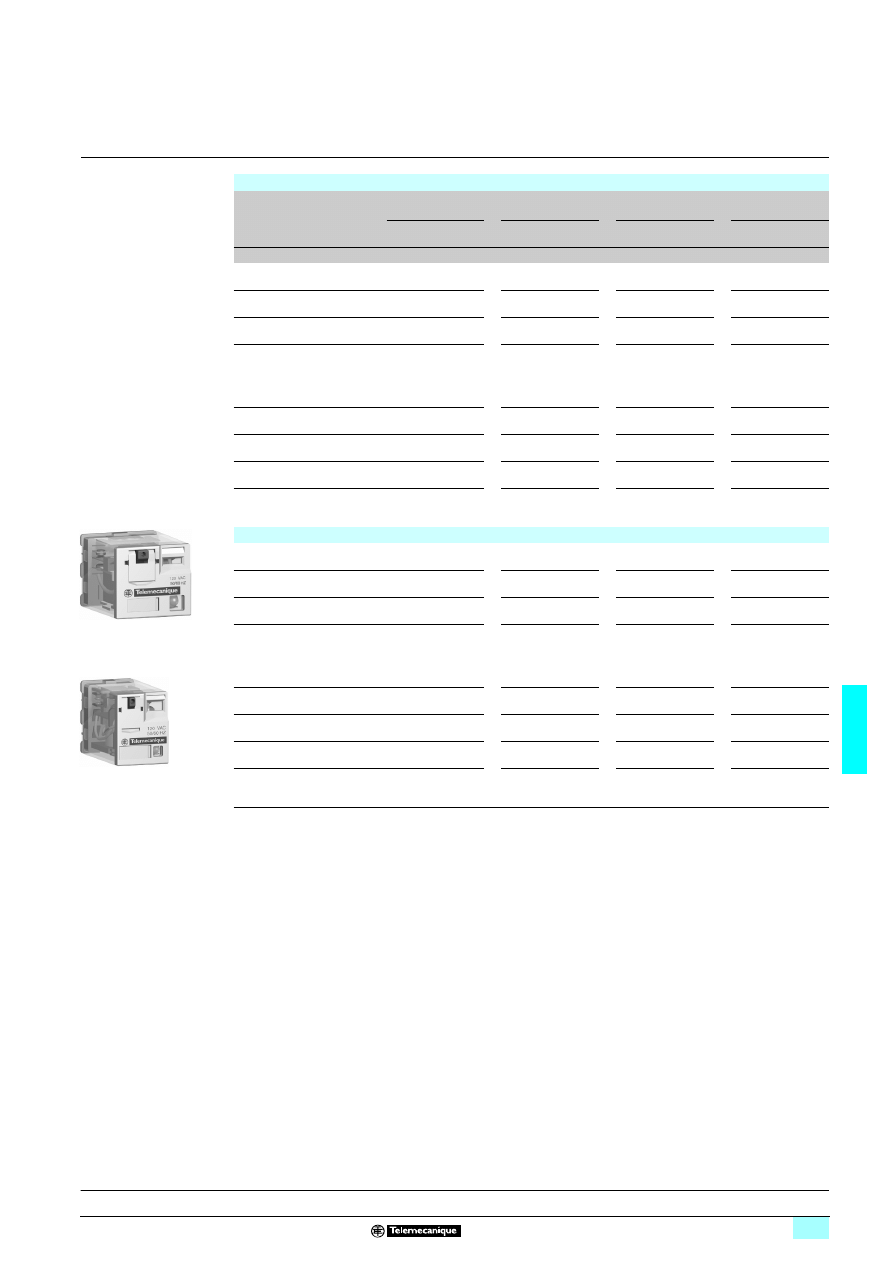
6/27
6
References
6
Zelio Relay - plug-in relays
6
RPM power relays
Power relays without LED
(sold in lots of 10)
Control circuit voltage
Number and type of contacts - Thermal current (Ith)
1 C/O - 15 A
2 C/O - 15 A
3 C/O - 15 A
4 C/O - 15 A
Unit
reference
Weight
Unit
reference
Weight
Unit
reference
Weight
Unit
reference
Weigh
t
V
kg
kg
kg
kg
c 12
RPM 11JD
0.024
RPM 21JD
0.036
RPM 31JD
0.054
RPM 41JD
0.068
c 24
RPM 11BD
0.024
RPM 21BD
0.036
RPM 31BD
0.054
RPM 41BD
0.068
c 48
RPM 11ED
0.024
RPM 21ED
0.036
RPM 31ED
0.054
RPM 41ED
0.068
c 110
RPM 11FD
0.024
RPM 21FD
0.036
RPM 31FD
0.054
RPM 41FD
0.068
a 24
RPM 11B7
0.024
RPM 21B7
0.036
RPM 31B7
0.054
RPM 41B7
0.068
a 48
RPM 11E7
0.024
RPM 21E7
0.036
RPM 31E7
0.054
RPM 41E7
0.068
a 120
RPM 11F7
0.024
RPM 21F7
0.036
RPM 31F7
0.054
RPM 41F7
0.068
a 230
RPM 11P7
0.024
RPM 21P7
0.036
RPM 31P7
0.054
RPM 41P7
0.068
Power relays with LED
(sold in lots of 10)
c 12
RPM 12JD
0.024
RPM 22JD
0.036
RPM 32JD
0.054
RPM 42JD
0.068
c 24
RPM 12BD
0.024
RPM 22BD
0.036
RPM 32BD
0.054
RPM 42BD
0.068
c 48
RPM 12ED
0.024
RPM 22ED
0.036
RPM 32ED
0.054
RPM 42ED
0.068
c 110
RPM 12FD
0.024
RPM 22FD
0.036
RPM 32FD
0.054
RPM 42FD
0.068
a 24
RPM 12B7
0.024
RPM 22B7
0.036
RPM 32B7
0.054
RPM 42B7
0.068
a 48
RPM 12E7
0.024
RPM 22E7
0.036
RPM 32E7
0.054
RPM 42E7
0.068
a 120
RPM 12F7
0.024
RPM 22F7
0.036
RPM 32F7
0.054
RPM 42F7
0.068
a 230
RPM 12P7
0.024
RPM 22P7
0.036
RPM 32P7
0.054
RPM 42P7
0.068
RPM 22F7
53
5205
RPM 32F7
5352
05
Presentation:
page 6/24
Characteristics:
pages 6/25 and 6/26
Dimensions:
pages 6/29 and 6/30
Schemes:
page 6/31
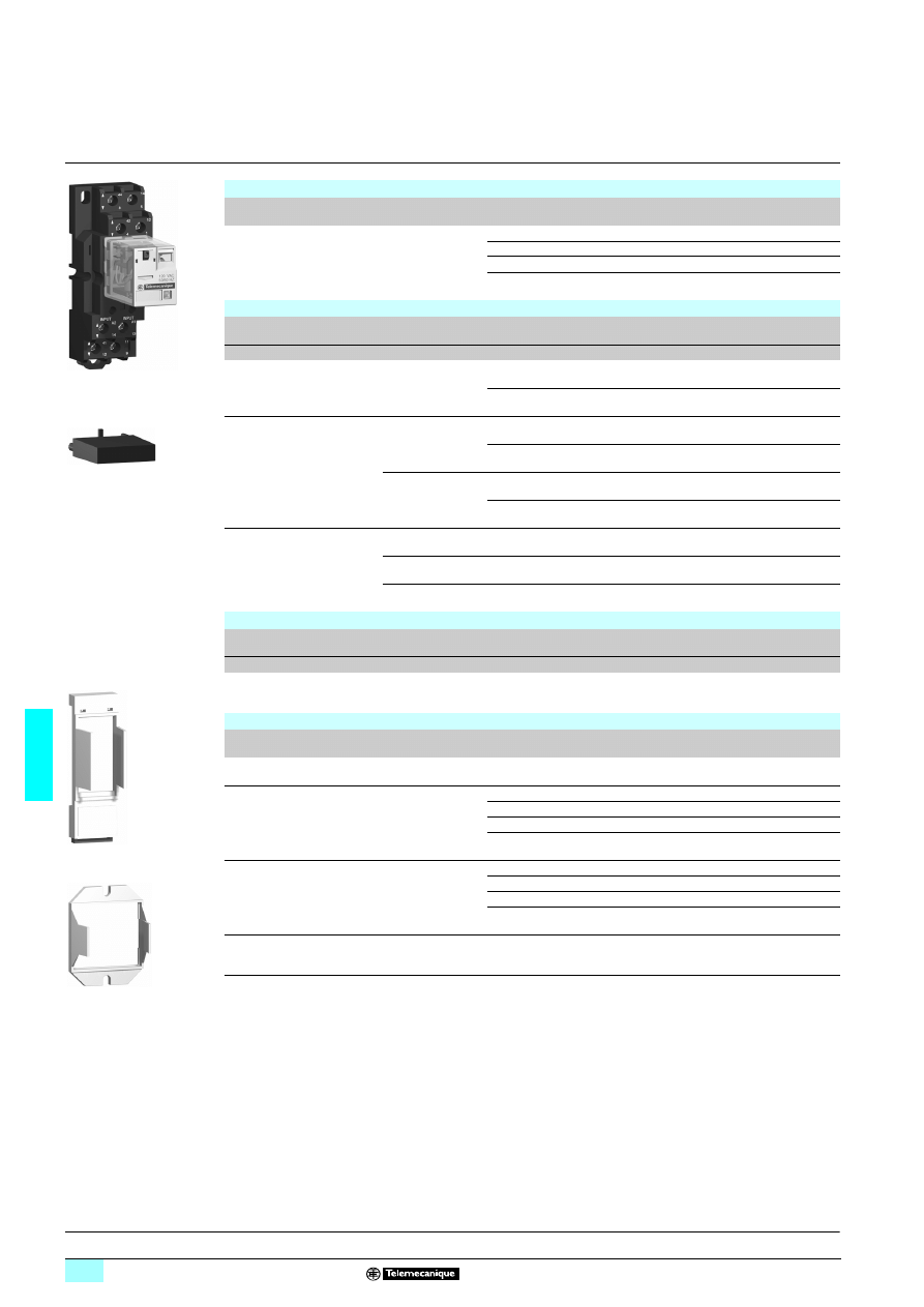
6/28
6
References
(continued)
6
Zelio Relay - plug-in relays
6
RPM power relays
Sockets
Contact terminal
arrangement
Connection
Relay type
Sold in
lots of
Unit
reference
Weight
kg
Mixed
Screw clamp
terminals
RPM 1ppp
10
RPZ F1
0.042
RPM 2ppp
10
RPZ F2
0.054
RPM 3ppp
10
RPZ F3
0.072
RPM 4ppp
10
RPZ F4
0.094
Protection modules
Description
Voltage
Socket
type
Sold in
lots of
Unit
reference
Weight
V
kg
Diode
c 6...250
RPZ F1
RPZ F2
20
RXM 040W
0.003
RPZ F3
RPZ F4
10
RUW 240BD
0.004
RC circuit
a 24...60
RPZ F1
RPZ F2
20
RXM 041BN7
0,010
RPZ F3
RPZ F4
10
RUW 241BM7
0,004
a 110...240
RPZ F1
RPZ F2
20
RXM 041FU7
0,010
RPZ F3
RPZ F4
10
RUW 241P7
0,004
Varistor
a/c 6..0.24
RPZ F1
RPZ F2
20
RXM 021RB
0.030
a/c 24...60
RPZ F1
RPZ F2
20
RXM 021BN
0.030
a/c 110...240
RPZ F1
RPZ F2
20
RXM 021FP
0.030
Timer module (1)
Description
Voltage
Socket
type
Reference
Weight
V
kg
Multifunction
a/c 24…240
RPZ F3
RPZ F4
RUW 101MW
0.020
Accessories
Description
For
use with
Sold in
lots of
Unit
reference
Weight
kg
Metal maintaining clamp
(for single-pole relays)
RPZ F1
20
RPZ R235
0.001
Mounting adapters for 5 rail (2)
RPM 1ppp
20
RPZ 1DA
0.004
RPM 2ppp
20
RXZ E2DA
0.004
RPM 3ppp
20
RPZ 3DA
0.004
RPM 4ppp
20
RPZ 4DA
0.006
Mounting adapters with fixing lugs for panel
RPM 1ppp
20
RPZ 1FA
0.002
RPM 2ppp
20
RXZ E2FA
0.002
RPM 3ppp
20
RPZ 3FA
0.003
RPM 4ppp
20
RPZ 4FA
0.004
Clip-in legends
(sheet of 108 legends)
All relays
10
RXZ L520
0.080
(1) See timer module description (selection of functions and time delays) on page 6/23
(2) Test button becomes inaccessible
RPZ F2 + relay RPM 22F7
5
352
06
RXM
p
41
ppp
53
5207
RPZ 1DA
53
5208
RPZ 3FA
535
209
Presentation:
page 6/24
Characteristics:
pages 6/25 and 6/26
Dimensions:
pages 6/29 and 6/30
Schemes:
page 6/31
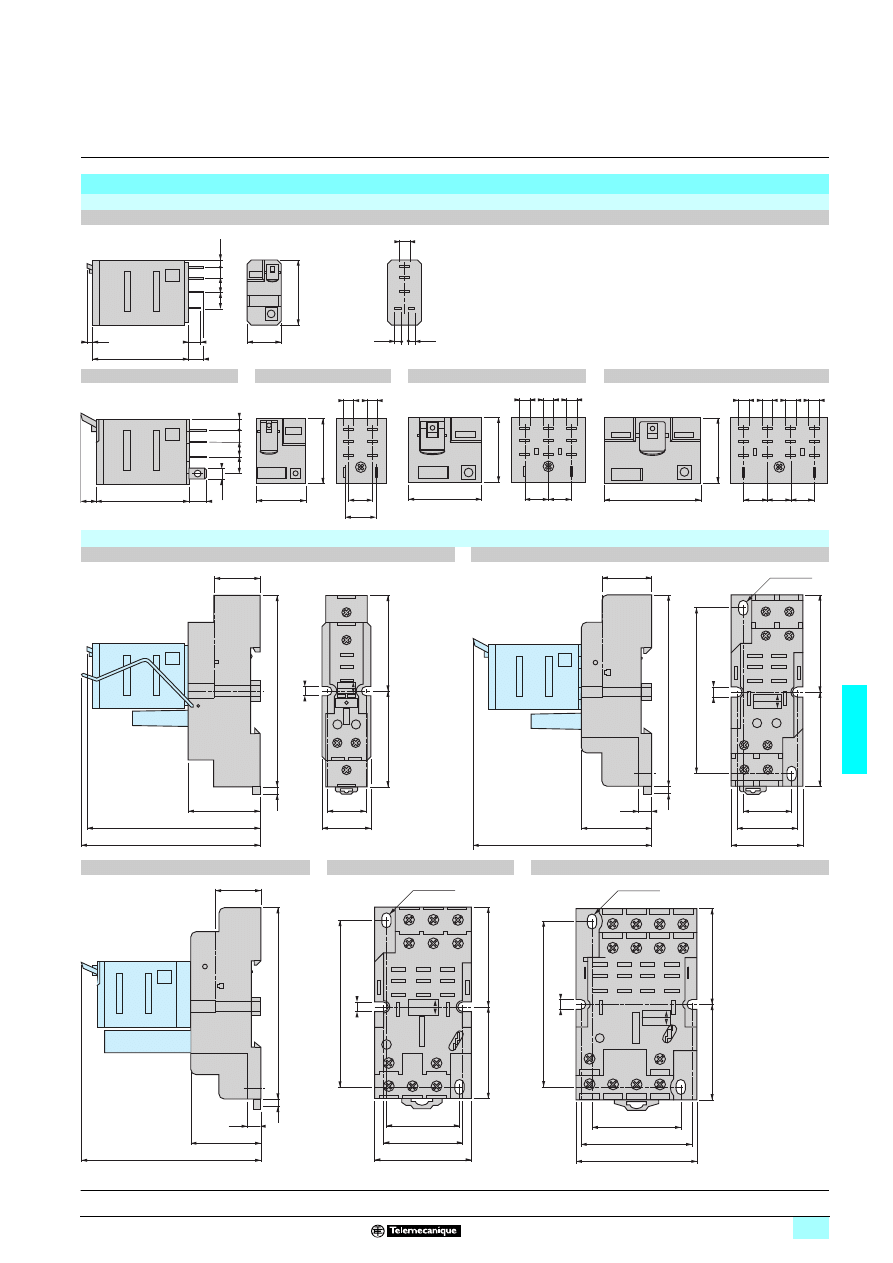
6/29
6
Dimensions
6
Zelio Relay - plug-in relays
6
RPM power relays
Dimensions
Power relays
RPM 1
Common side view
RPM 2
RPM 3
RPM 4
Sockets
RPZ F1
RPZ F2
Common side view
RPZ F3
RPZ F4
7
6
2
14
41
27
4,5
6,5
6
5
3,5
2,5
2,5
7
39
7
6,5
6
5
4
4,5
27
21
10
15
4,5 4,5
31
27
10
10
4,5 4,5 4,5
40
10
10
10
27
4,5 4,5 4,5 4,5
14
5
12
1
A2
14
A1
13
11
9
31
19
17
21
4
71
80
40
80
4
40
44
8
14
5
42
4
12
1
A2
14
A1
13
41
12
11
9
30
26
19
30
40
40
4
19
8
76
80
68
4
Ø4,5 x 6
30
76
80
4
19
8
28
40
37
40
40
68
4
44
8
24
6
14
5
42
4
A2
14
A1
13
41
12
21
10
11
9
22
2
12
1
Ø4,5 x 6
36
46
50
40
40
68
4
14
5
24
6
34
7
44
8
A2
14
A1
13
41
12
31
11
21
10
11
9
12
1
22
2
32
3
42
4
Ø4,5 x 6
Presentation:
page 6/24
Characteristics:
pages 6/25 and 6/26
References:
pages 6/27 and 6/28
Schemes:
page 6/31
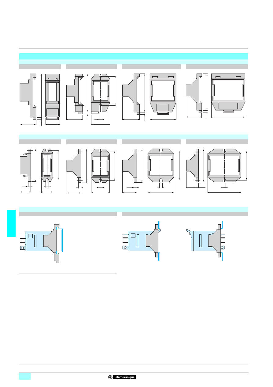
6/30
6
Dimensions
(continued)
6
Zelio Relay - plug-in relays
6
RPM power relays
Dimensions
(continued)
Mounting adapters for 5 rail
RPZ 1DA
RXZ E2DA
RPZ 3DA
RPZ 4DA
Mounting adapters with fixing lugs for panel
RPZ 1FA
RXZ E2FA
RPZ 3FA
RPZ 4FA
Mounting
Mounting adapters for 5 rail (1)
Mounting adapters with fixing lugs for panel
(1) Test button becomes inaccessible
23
24
49,5
2,5
38
4
24
23
48
3
34
23
50
2,5
44
20
50
2,5
38
43
3,5
5
16,5
16
38
3,5
4
19
43
24
38
19
3,5
4
43
34
16
3,5
4
38
43
44
Presentation:
page 6/24
Characteristics:
pages 6/25 and 6/26
References:
pages 6/27 and 6/28
Schemes:
page 6/31
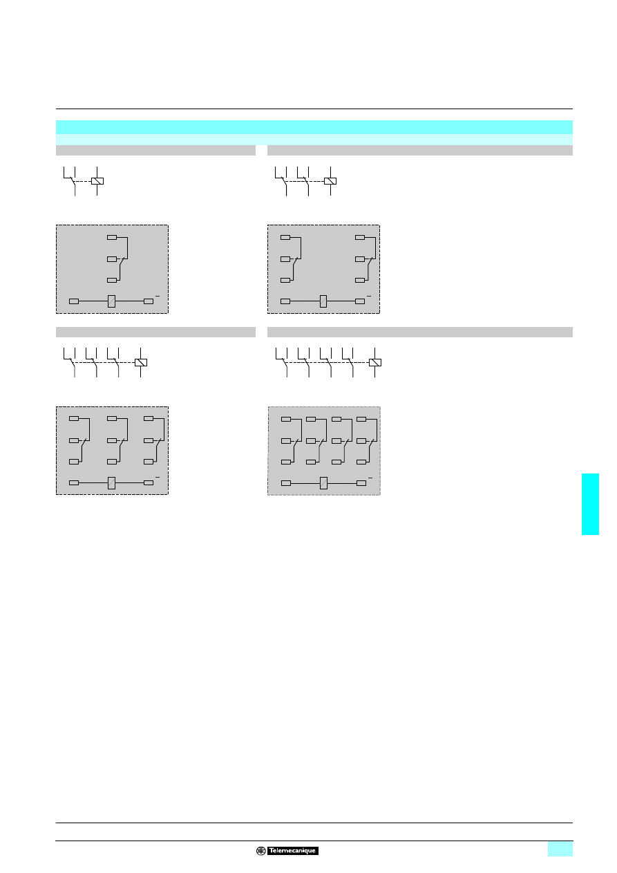
6/31
6
Schemes
6
Zelio Relay - plug-in relays
6
RPM power relays
Schemes
Power relays
RPM 1ppp
RPM 2ppp
RPM 3ppp
RPM 4ppp
Symbols shown in blue correspond to Nema marking.
1
12
5
14
9
11
13
A1
14
A2
(
+
)
( )
A2
A1
11
14
12
1
12
3
14
5
11
2
22
4
24
6
21
7
A1
8
A2
(
+
)
( )
A2
A1
21
24
22
11
14
12
1
12
5
14
9
11
2
22
6
24
10
21
4
42
8
44
12
41
13
A1
14
A2
(
+
)
( )
A2
A1
21
24
22
41
44
42
11
14
12
(
+
)
1
12
5
14
9
11
2
22
6
24
10
21
3
32
7
34
11
31
4
42
8
44
12
41
13
A1
14
A2
( )
A2
A1
21
24
22
31
34
32
41
44
42
11
14
12
Presentation:
page 6/24
Characteristics:
pages 6/25 and 6/26
References:
pages 6/27 and 6/28
Dimensions:
pages 6/29 and 6/30
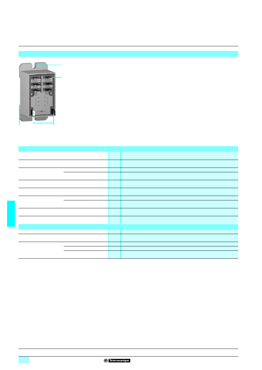
6/32
6
Presentation,
characteristics
6
Zelio Relay - plug-in relays
6
RPF power relays
With clamp fixing
RPF power relays with 2 C/O or 2 N/O contacts comprise:
1
Four or six Faston type pins.
2
Two relay supply pins.
3
A locating slot for mounting on 5 rail.
4
Two fixing holes for panel mounting.
Presentation of the range
5
3521
0
4
1
3
2
General characteristics
Conforming to standards
IEC/EN 61810-1 (iss. 2), UL 508, CSA C22-2 n°14
Product certifications
UL, CSA
Ambient air temperature
around the device
Storage
°C
- 40...+ 85
Operation
°C
- 40...+ 55
Vibration resistance
Conforming to IEC 60068-2-6
>10 gn (10...55 Hz)
Degree of protection
Conforming to IEC/EN 60529
IP 40
Shock resistance
conforming to IEC/EN 60068-2-27
Opening
10 gn
Closing
10 gn
Protection category
RT IV
Mounting position
Any
Insulation characteristics
Rated insulation voltage (Ui)
Conforming to IEC/EN 60947
V
250
Rated impulse withstand voltage (Uimp)
kV
3.6 (1.2/50
μs)
Dielectric strength
(rms voltage)
Between coil and contact
a V
2500
Between poles
a V
2500
Between contacts
a V
1500
References:
page 6/34
Dimensions, schemes:
page 6/35
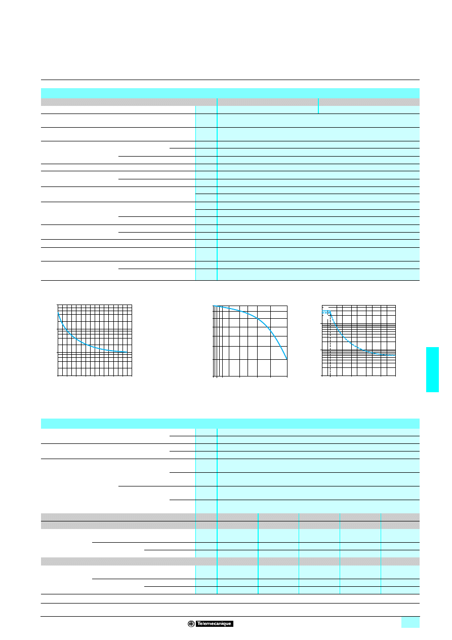
6/33
6
Characteristics
(continued)
6
Zelio Relay - plug-in relays
6
RPF power relays
With clamp fixing
Contact characteristics
Relay type
RPF 2App
RPF 2Bpp
Number and type of contacts
2 N/O
2 C/O
Contact materials
AgSnO
2
Conventional thermal
current (Ith)
For ambient
temperature y 40°C
A
30 (when mounted with 13 mm gap between two relays)
25 (when mounted side by side without a gap)
Rated operational current
in utilisation categories
AC-1 and DC-1
Conforming to IEC
N/O
A
30
N/C
A
3
Conforming to UL
A
30
Switching current
Minimum
mA
10
Switching voltage
Maximum
V
a/c 250 (IEC)
Minimum
V
17
Rated load (resistive)
30 A / 250 aV - 30 A /28 cV (when mounted with 13 mm gap between two relays)
25 A / 250 aV - 25 A /28 cV (when mounted side by side without a gap)
Switching capacity
Maximum
7500 aVA / 840 W (when mounted with 13 mm gap between two relays)
6250 aVA / 700 W (when mounted side by side without a gap)
Minimum
mW
170
Maximum operating rate
In operating cycles/hour
No-load
18 000
Under load
1200
Utilisation coefficient
10 %
Mechanical durability
In millions of operating cycles
5
Electrical durability
In millions of operating
cycles
Resistive load
0.05 (N/O contact only)
Inductive load
See curves below
Electrical durability of contacts
Resistive load a
Reduction coefficient for inductive load a
(depending on power factor cos
ϕ)
Maximum switching capacity on resistive load
c
Durability (inductive load) = durability (resistive load) x reduction coefficient.
A
RPF 2ppp: 30 A
B
RPF 2ppp: 25 A
Coil characteristics
Average consumption
a
VA
4
c
W
1.7
Drop-out voltage threshold
a
u 0.15 Uc
c
u 0.1 Uc
Operating time
(response time)
Between coil
energisation and
making of the
On-delay contact
a
ms
20
c
ms
20
Between coil
de-energisation
and making of the
Off-delay contact
a
ms
20
c
ms
20
Control circuit voltage Uc
V
12
24
110
120
230
Relay control voltage codes
JD
BD
FD
–
–
DC
Average resistance
at 20 °C ± 10%
Ω
86
350
7255
–
–
Operating voltage
limits
Min.
V
9.6
19.2
88
–
–
Max.
V
13.2
26.4
121
–
–
Relay control voltage codes
–
B7
–
F7
P7
AC
Average resistance
at 20 °C ± 15%
Ω
–
250
–
1600
6500
Operating voltage
limits
Min.
V
–
19.2
–
96
184
Max.
V
–
26.4
–
132
253
104
2
0
1
4
3
5
6
7
8
107
105
106
D
u
rabi
lity
(
N
umber
of op
er
at
ing c
y
c
les
)
Switching capacity (kVA)
0,3
0,5
0,6
10,8
0,4
0,2
0,4
0,6
0,8
1
cos
ϕ
R
educ
ti
o
n
c
oeff
ic
ient (
A
)
0,1
1
200
250
0
50
28
100
150
10
B
A
C
u
rr
ent
c
Voltage c
References:
page 6/34
Dimensions, schemes:
page 6/35
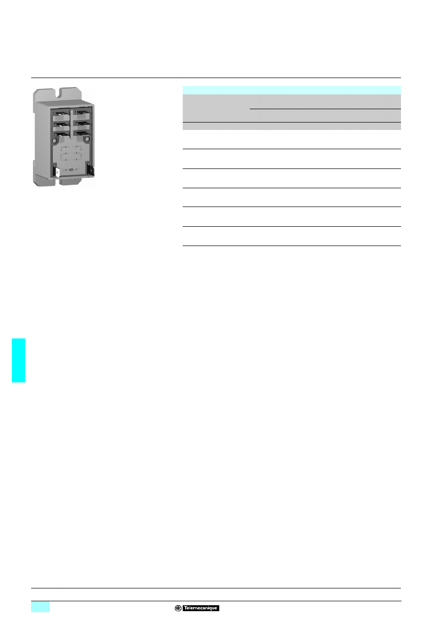
6/34
6
References
6
Zelio Relay - plug-in relays
6
RPF power relays
With clamp fixing
Power relays
(sold in lots of 10)
Control
circuit voltage
Number and type of contacts - Thermal current (Ith)
2 N/O - 30 A (1)
2 C/O - 30 A (1)
Unit
reference
Unit
reference
Weight
V
kg
c 12
RPF 2AJD
RPF 2BJD
0.086
c 24
RPF 2ABD
RPF 2BBD
0.086
c 110
RPF 2AFD
RPF 2BFD
0.086
a 24
RPF 2AB7
RPF 2BB7
0.086
a 120
RPF 2AF7
RPF 2BF7
0.086
a 230
RPF 2AP7
RPF 2BP7
0.086
(1) 30 A when mounted with 13 mm gap between two relays and 25 A when mounted side by side
without a gap.
RPF 2B
pp
Characteristics:
pages 6/32 and 6/33
Dimensions, schemes:
page 6/35
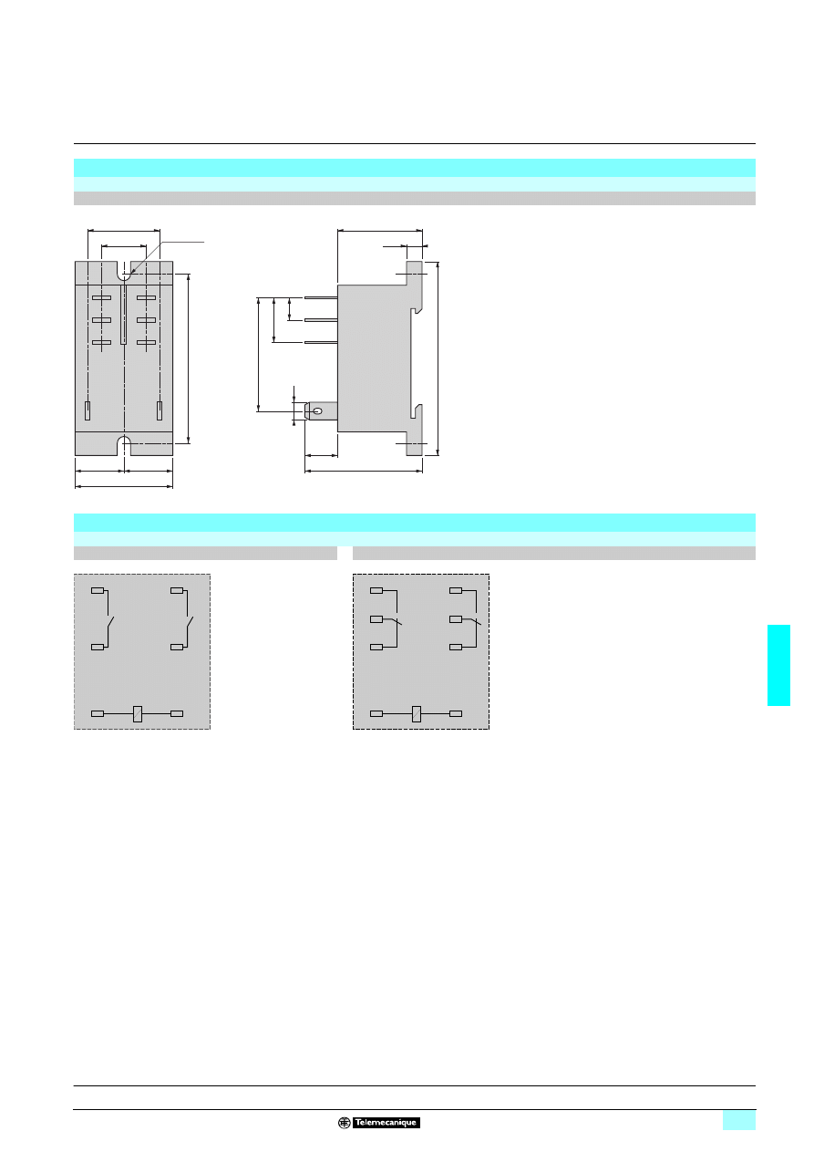
6/35
6
Dimensions,
schemes
6
Zelio Relay - plug-in relays
6
RPF power relays
With clamp fixing
Dimensions
Power relays
RPF 2App, RPF 2Bpp
Schemes
Power relays
RPF 2App
RPF 2Bpp
Symbols shown in blue correspond to Nema marking.
42
15
8
6
30
69
12
42
34
=
=
26
16
4,5
Ø 2 x 4,5
60
6
14
8
11
2
24
4
21
1
A1
0
A2
6
14
8
11
7
12
2
24
4
21
3
22
1
A1
0
A2
Characteristics:
pages 6/32 and 6/33
References:
page 6/34
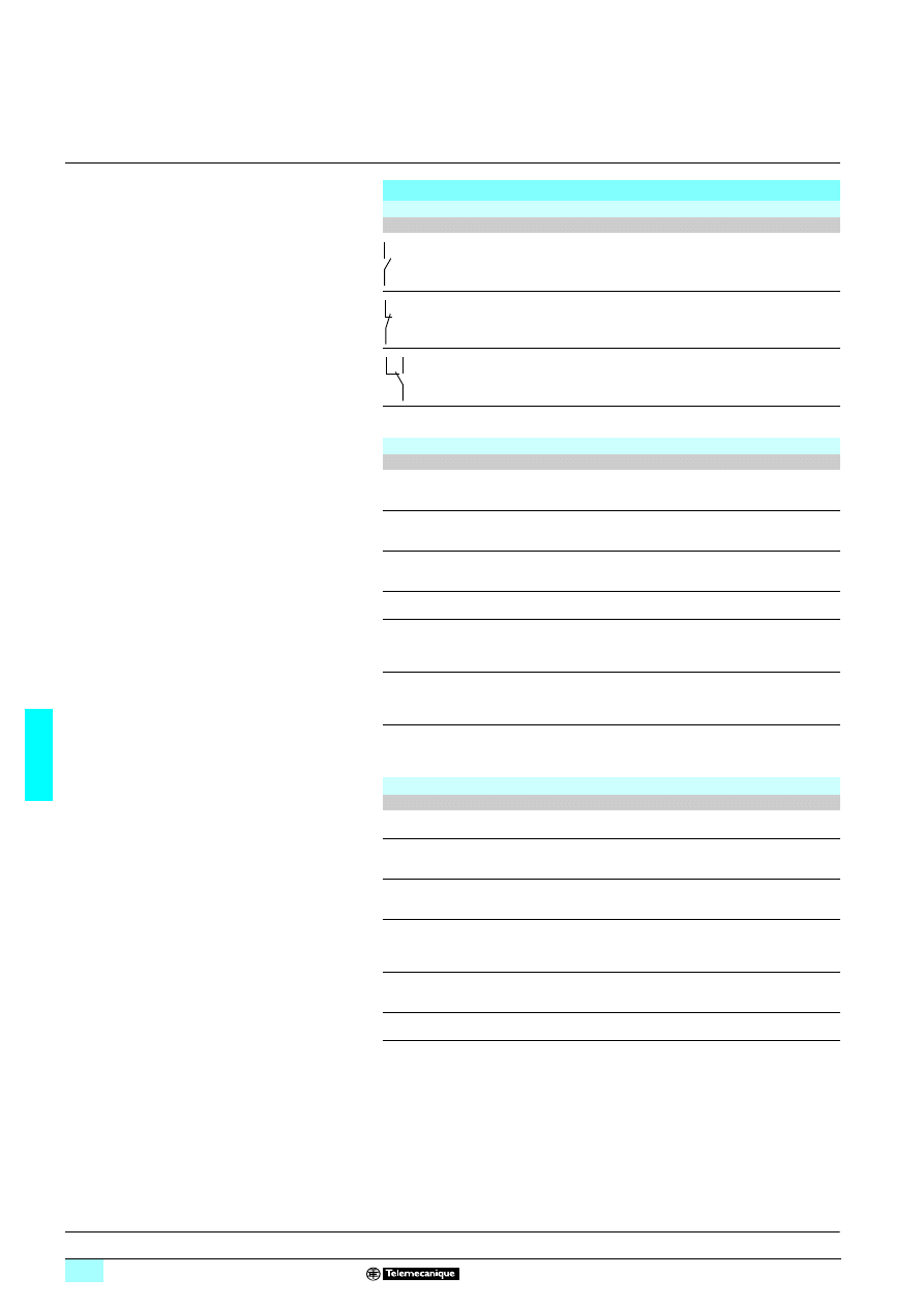
6/36
6
Technical presentation
6
Zelio Relay - plug-in relays
6
Relays
Contact types
Symbol
Configuration
EU
USA
Make contact
(Normally Open)
NO
SPST-NO
DPST-NO
nPST-NO (1)
Break contact
(Normally Closed)
NC
SPST-NC
DPST-NC
nPST-NC (1)
Changeover Contact
CO
SPDT
DPDT
nPDT (1)
Utilisation categories
Category
Type of current
Applications
AC-1
a single-phase
a 3-phase
Resistive or slightly inductive loads.
AC-3
a 3-phase
Starting and braking of squirrel cage motors; reversing
direction of rotation only after stopping of motor.
AC-4
a 3-phase
Starting of squirrel cage motors, inching. Plugging,
reversing direction of rotation.
DC-1
c
Resistive or slightly inductive loads (2).
AC-14
a single-phase
Control of electromagnetic loads (< 72 VA), auxiliary
control relays, power contactors, electromagnetic
solenoid valves and electromagnets.
AC-15
a single-phase
Control of electromagnetic loads (> 72 VA), auxiliary
control relays, power contactors, electromagnetic
solenoid valves and electromagnets.
DC-13
c
Control of electromagnetic loads, auxiliary control relays,
power contactors, magnetic solenoid valves and
electromagnets.
Protection categories
Category
Explanation
Condition
RT 0
Unenclosed relay Relay not provided with a protective case.
RT I
Dust protected
relay
Relay provided with a case which protects its mechanism
from dust.
RT II
Flux-proof relay
Relay capable of being automatically soldered without
allowing the migration of solder fluxes beyond the
intended areas.
RT III
Wash-tight relay
Relay capable of being automatically soldered and then
washed to remove flux residues without risk of ingress of
flux or washing solvents.
RT IV
Sealed relay
Relay provided with a case which has no venting to the
outside atmosphere.
RT V
Hermetically
sealed relay
Sealed relay having an enhanced level of sealing.
(1) n = number of contacts.
(2) The switchable voltage can be doubled, for an equal current, by connecting two contacts in
series.
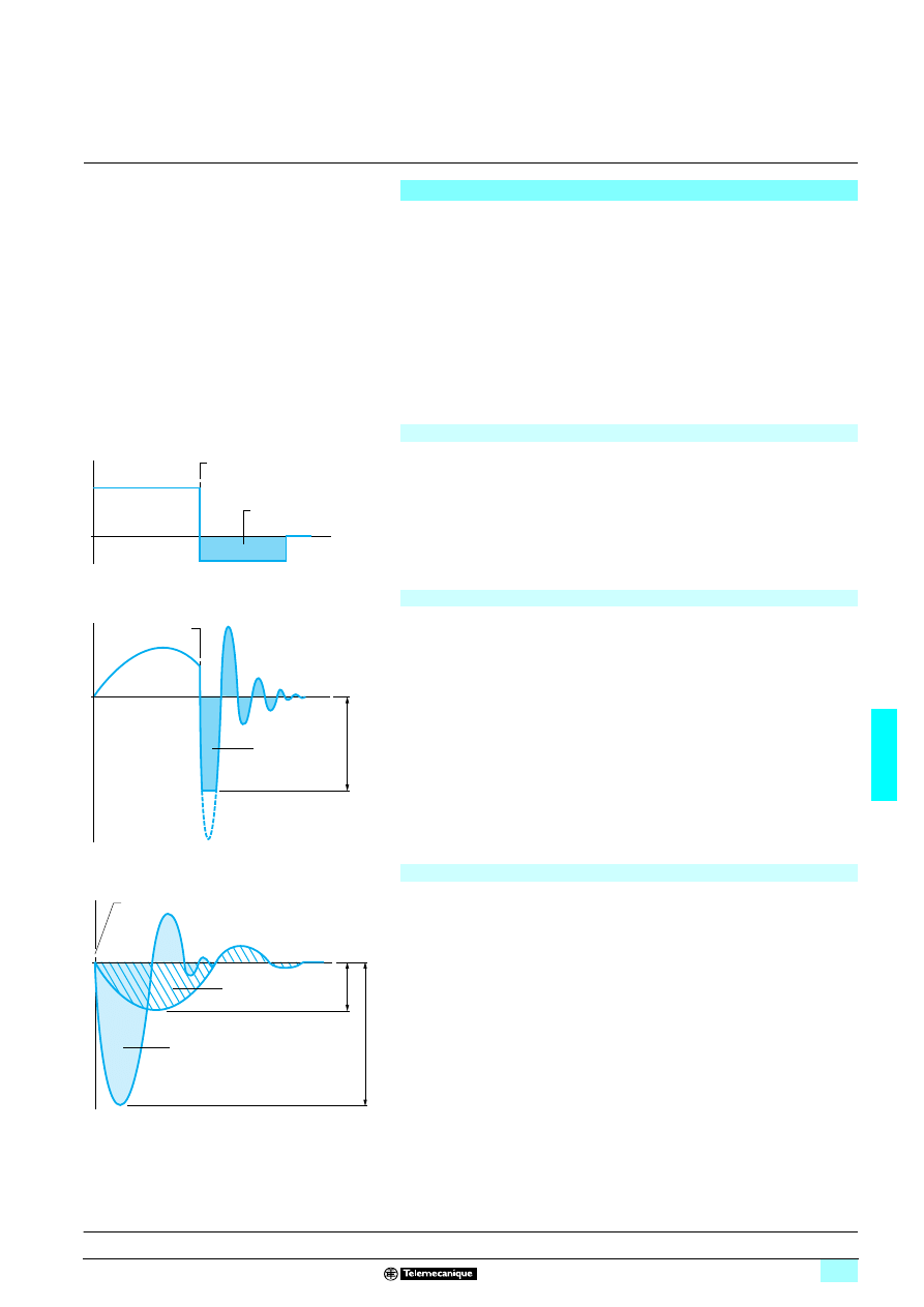
6/37
6
Presentation
6
Zelio Relay - plug-in relays
6
Protection modules
Whenever an inductive load is de-energised (coil of a relay or of a contactor), an
overvoltage appears at its terminals. This voltage peak can reach several thousand
volts and a frequency of several MHz.
It is likely to disturb the operation of automation systems which contain electronic
devices.
Protection modules are used to reduce the voltage peak on de-energisation and
they therefore limit the energy of interference signals to a level that will not disturb
surrounding coils and electronic devices.
These modules are used to avoid:
v electromagnetic compatibility problems,
v the deterioration of contact materials,
v the destruction of insulation due to overvoltage,
v the destruction of electronic components.
Diode protection module (with or without LED)
Coil voltage with diode protection module (
c
only)
b Advantages
v accumulation of energy allowing current flow in the same direction,
v absence of any voltage peaks at the coil terminals,
v low cost.
b Disadvantages
v increase in relay drop-out time (3 to 4 times the usual time),
v no polarity protection,
v de-energisation of the relay.
Protection module with varistor
Coil voltage with varistor protection module (
a
and
c
)
b Advantages
v can be used with a and c supply,
v voltage peak limited to about 2 Un,
v little effect on relay drop-out time.
b Disadvantages
v no modification of coil's own oscillating frequency,
v limitation of switching frequency.
Protection module with RC circuit
Coil voltage with RC circuit protection module (
a
only)
S1 = S2 = Energy released
b Advantages
v coil oscillating frequency reduced to about 150 Hz,
v voltage peak limited to 3 Un,
v little effect on relay drop-out time.
b Disadvantages
v no protection for low voltages.
U
t
Supply voltage
Energy released
Break
U
t
Energy
released
Break
Li
mi
ta
ti
on of
v
o
lt
age
pe
ak
s
S1
U1
U2
U
t
Break
S2 (with RC)
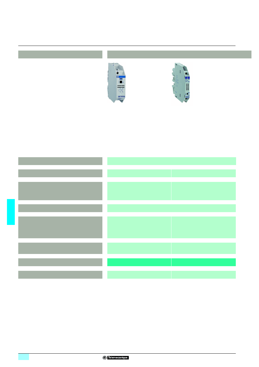
6/38
6
Selection guide
6
Interfaces
6
Interfaces for discrete signals
Applications
Electromechanical interface modules
Functions
Input
Width (mm)
17.5
9.5
Contact arrangement
1 N/O
2 N/O
1 C/O
1 N/O
Thermal current
–
Control voltages
c 110…127 V
z 24 V, 48 V
a 115…127 V
a 230/240 V
c 24 V, 48 V
a 115…127/50 Hz
a 115…127/60 Hz
a 230…240/50-60 Hz
Indication
Mechanical for contacts
and/or LED for control
LED for control
References
ABR-1E
ABR-2E
Pages
6/40
6/46
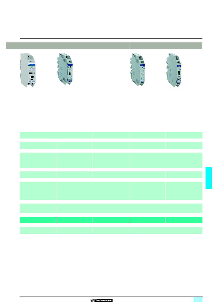
6/39
6
6
6
Solid state interface modules
Output
Input and output
Very low level switching
Input
Output
17.5
12
17.5
9.5
9.5/17.5
1 N/O
2 N/O
1 C/O
1 N/C + 1 N/O
1 N/O
1 C/O
–
12 A
5 A
–
5 A
c 24 V
z 24 V, 48 V
a 115…127 V
a 110 V
c 24 V
c 5, 24, 48 V
a 115…127/50 Hz
a 120…127/60 Hz
a 230…240/50 Hz
a 230…240/60 Hz
c 24 V
Mechanical for contacts
and/or LED for control
LED for control
ABR-1S
ABR-2S
ABR-2
pB312B
ABS-2E
ABS-2S
6/40
6/46
6/46
6/52
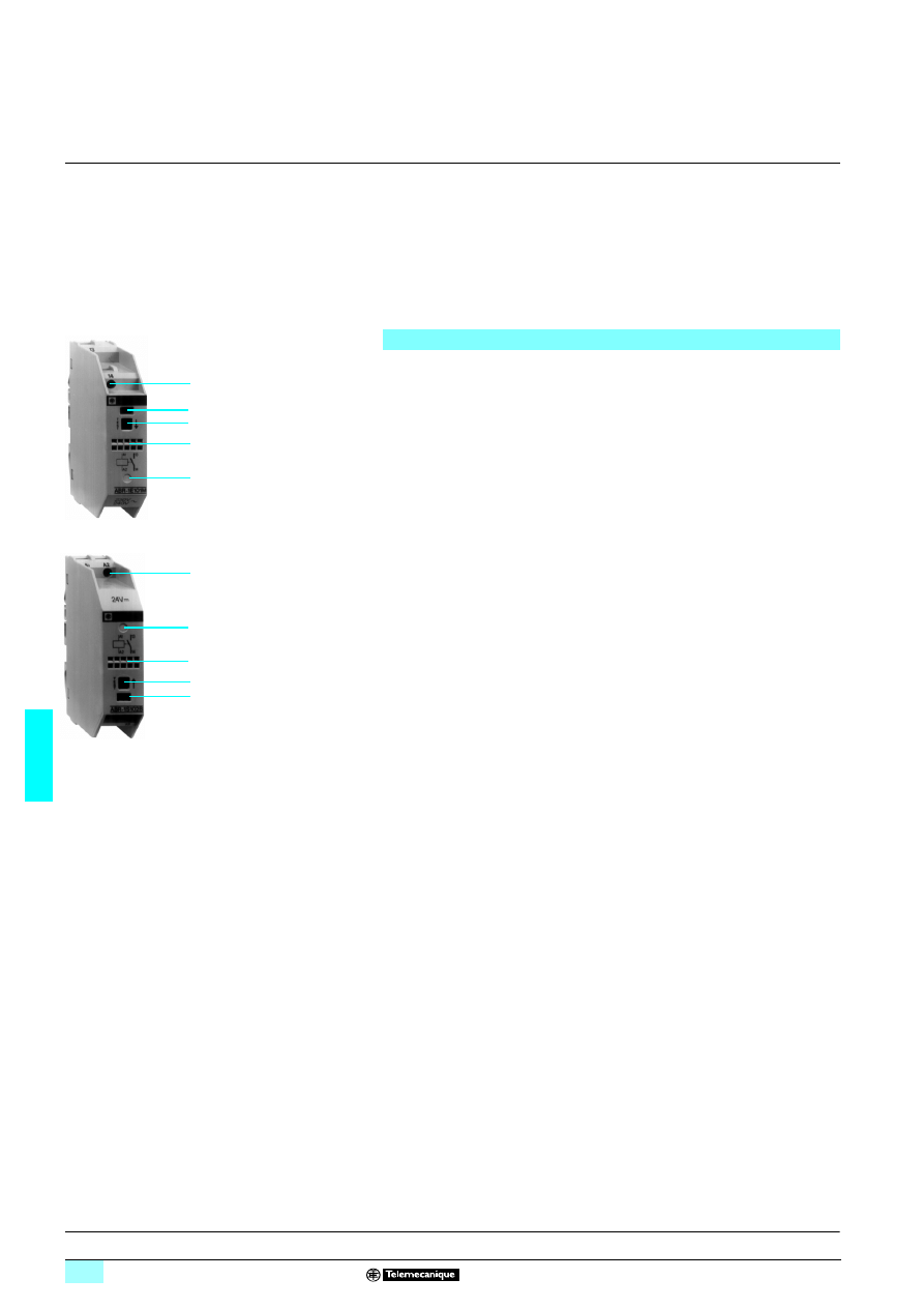
6/40
6
Presentation
6
Interfaces
6
For discrete signals
Electromechanical interface modules
ABR-1 electromechanical interface modules are supplied in the form of compact
modules, 17.5 mm wide.
They are designed for interfacing discrete digital control signals exchanged within an
automated system between the processing unit (PLC, numerical controller, etc) and
the other components (contactors, solenoid valves, indicator lamps, proximity
sensors, etc).
These products are based on contactor technology and are notable for their excellent
adaptation to industrial environments, ensured by the fact that they conform to the
most recent IEC 947-5-1 standards.
The ABR-1 range comprises 2 families :
Input interfaces
Input interfaces are designed for switching input signals to the processor and are
characterized by their high degree of contact reliability : less than 1 fault per 100
million operating cycles at c 17 V, 5 mA.
The switching level is sufficiently high to ensure that the interfaces can directly
control most contactors and indicator lamps.
Output interfaces
Output interfaces are designed for the control of preactuators (contactors, solenoid
valves, etc) for signalling devices (indicators lamps, audible warnings, etc). They are
characterized by a high switching capacity and an average durability 5 times greater
than that of traditional interface modules which incorporate standard relays.
1
Override contacts by pressing button (not holding it down) for a simple and quick
test during setting up or maintenance operations on the installation
2
Green indicator showing the mechanical position of the contacts
3
LED indicating the control signal state
4
Channel identification : 5 individual characters for AB1-R/G or one AB1-SA2
marker tag
5
Connection by screw clamp terminal enabling easy attachment of 2 wires per
terminal. The layout of the connection terminals for both families (input and output)
is designed for rational wiring and a clear separation between the incoming
(processing) and outgoing (power and process control) circuits.
Composition
8
1626
4
5
2
1
4
3
816
265
5
3
4
1
2
Characteristics:
pages 6/41 and 6/42
Curves:
page 6/43
References:
page 6/44
Dimensions, schemes:
page 6/45
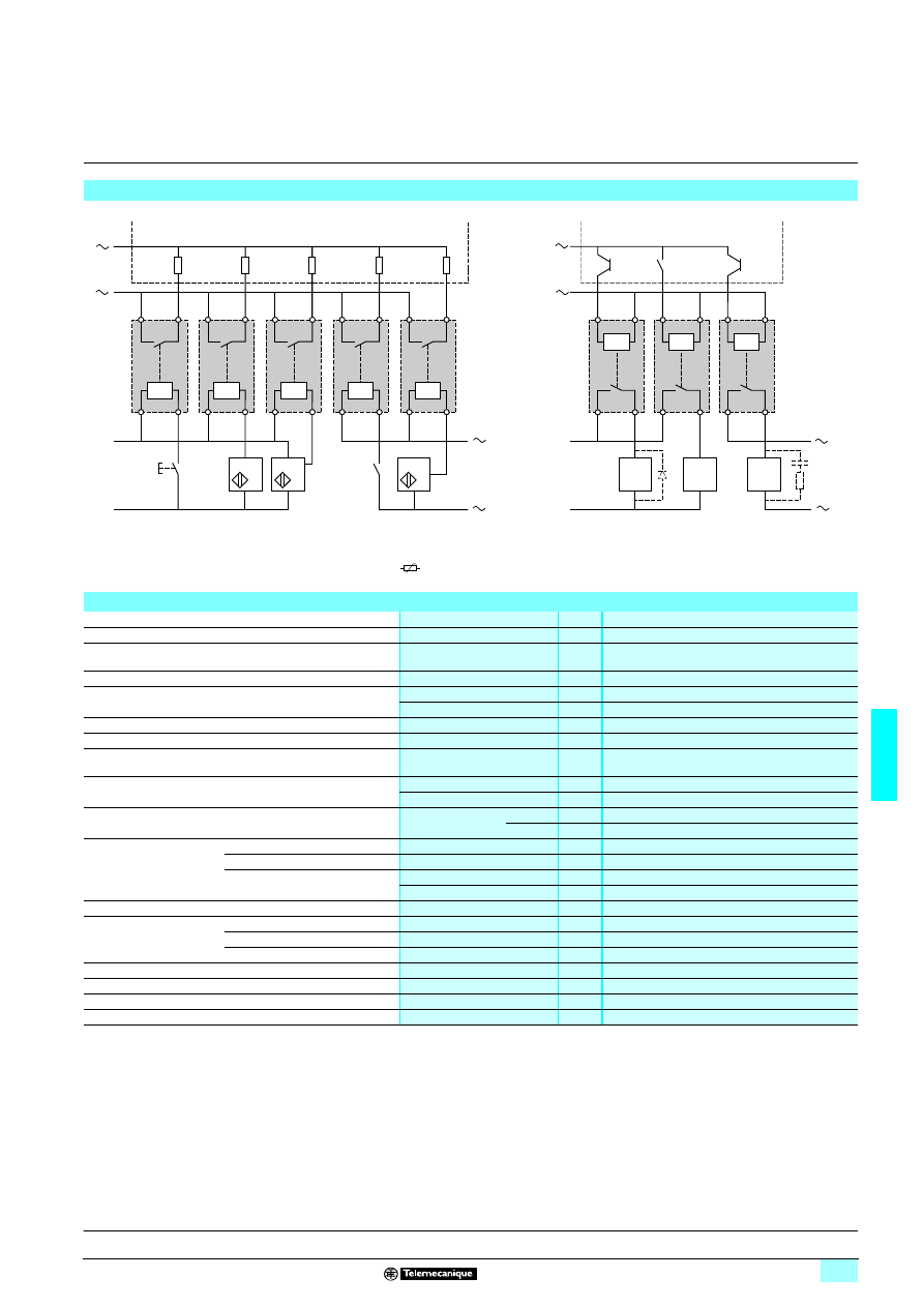
6/41
6
Characteristics
6
Interfaces
6
For discrete signals
Electromechanical interface modules
(1) Essential on inductive loads (can be replaced with peak limiter
).
Examples of applications with PLCs
–
/
+
/
–
+
A2
A1
A2
A1
A2
A1
A2
A1
Pushbuttons
Series contacts
2-wire
sensors
3-wire
sensors
Pushbuttons
Series contacts
2-wire
sensors
PLC
Positive logic discrete inputs
–
/
+
/
–
+
24...125 V
...240 V
A1
A2
(1)
(1)
A1
A2
A1
A2
PLC
Positive logic transistor (or relay) outputs
Environment
Conforming to standards
IEC 947-5-1
Product certifications
UL, CSA, BV, LROS, DNV
Degree of protection
Conforming to IEC 529
(protection against direct contact)
IP 00
Protective treatment
“TC”
Flame resistance
Conforming to IEC 695-2-1
Incandescent wire
°C
850
Conforming to UL 94
V0
Shock resistance
Conforming to IEC 68-2-27
Semi-sinusoidal waves 11 ms
50 gn
Vibration resistance
Conforming to IEC 68-2-6
10…55 Hz
6 gn
Resistance to electrostatic
charges
Conforming to IEC 801-2
Level 3
kV
8
Resistance to rapid
transients
Conforming to IEC 801-4
On power supply
kV
2
On I/O
kV
1
Resistance to shock
waves
Conforming to IEC 255-4
Waveform
1.2/50 ms ; 0.5 J
U
≤ 50 V
kV
0.5
U >
50 V kV
2.5
Cross-sections which
may be connected
Flexible cable with no cable end
1 or 2-wire
mm
2
0.6…2.5
Flexible cable with cable end
1 or 2-wire
mm
2
0.34…2.5
Rigid cable
1-wire
mm
2
0.27…4
2-wire
mm
2
0.27…2.5
Operating position
Any
Ambient air temperature
around the device
Unrestricted operation
°C
- 5…+ 40
Permissible at Un
°C
- 20…+ 60
Storage
°C
- 40…+ 70
Operating altitude
m
≤ 3000
Installation category
Conforming to IEC 947-1
II
Degree of pollution
Conforming to IEC 947-5-1
3
Mounting
Standard rails
5
1 4
Presentation:
page 6/40
Curves:
page 6/43
References:
page 6/44
Dimensions, schemes:
page 6/45
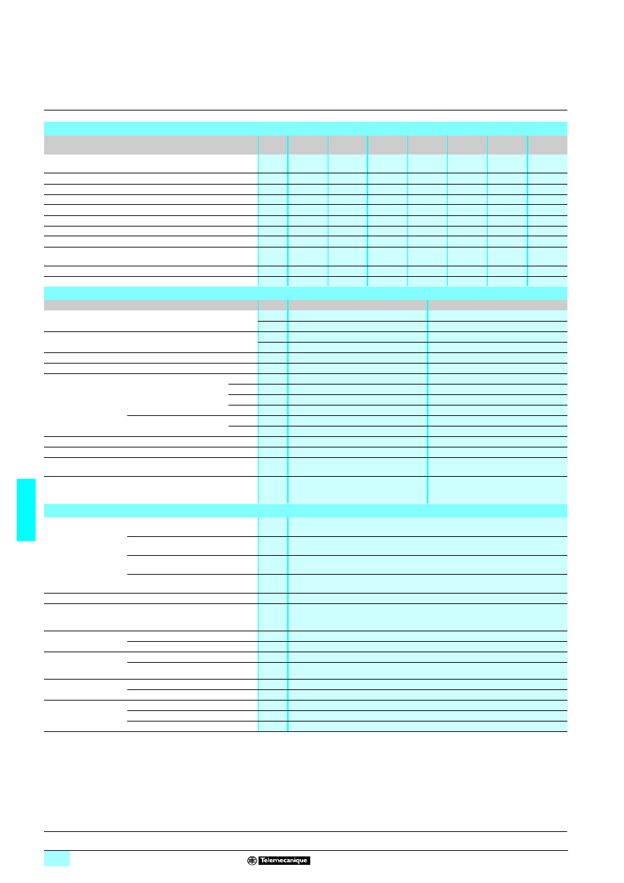
6/42
6
Characteristics
(continued)
6
Interfaces
6
For discrete signals
Electromechanical interface modules
Control circuit characteristics
(40°C ambient temperature)
Type of interface
ABR
1Sp02B
ABR
1ppp8B
ABR
1ppp8E
ABR
1Ep12F
ABR
1ppp1F
ABR
1Ep11M
ABR
1Ep01M
Rated voltage (Uc)
V
c 24
z 24
z 48
c
110...127
a
115...127
a
230...240
a
230...240
Current frequency
Hz
–
50/60
50/60
–
50/60
50/60
50/60
Energization threshold (at ± 5 %)
V
15
16.5
34
75
86
170
164
Maximum operating voltage
c / a
V
30
30
53
140
140
264
264
Maximum drop-out (at ± 5 %) voltage (Uo)
c / a
V
3.2
3.8
8.5
16
34
68
78
Maximum current (Un)
c / a
mA
62
62/55
36/32
15
8
7
5.5
Minimum holding current
c / a
mA
6.6
4.9/5.2
4.7/5.4
1.5
2.4
2
1.5
Maximum dissipated power
50 Hz/60 Hz
W
1.5
1.5
1.5
1.5
1.5
1.5
1.5
Disappearance of voltage
maximum time up to which contact is maintained
ms
3
8
10
10
6
5
6
Display of control circuit by LED
No
Yes
Yes
Yes
Yes
Yes
No
Built-in protection reversed polarity
Yes
Yes
Yes
Yes
–
–
–
Contact characteristics
Type of interface
ABR 1Epppp
ABR 1Spppp
Maximum switching voltage
a V
252
252
c V
125
125
Maximum rated
operating voltage Ue
Conforming to IEC 947-5-1
a V
230
230
c V
125
125
Operating current frequency
Hz
50/60
50/60
Thermal current Ith
Conforming to IEC 947-1
A
2
12
Rated operating
current (Ie)
per 1 million operating
cycles
Conforming to IEC 947-5-1
Ue : a 230 V
AC12
A
2
4
AC13
A
1
1
AC14
A
1
1
AC15
A
1
1
Conforming to IEC 947-5-1
Ue : c 24 V
DC12
A
2
5
DC13
A
1
1
Minimum switching capacity
mA
3
3
Minimum switching voltage
V
17
17
Protection against
short-circuits
For Ik
≤ 2.5 kA (a) and ≤ 100 A (c)
Type and value of recommended fuse
A
gG/gF : 16
gG/gF : 16
Low power switching
reliability of contacts
(17 V - 5 mA)
Number of faults
per "n" million operating cycles
10
-8
10
-8
Other characteristics
Operating time
at Un and at 20 °C
Between energization of coil and
closing of N/O contact
ms
≤ 12
Between energization of coil and
opening of N/C contact
ms
≤ 12
Between de-energization of coil and
opening of N/O contact
ms
≤ 12
Between de-energization of coil and
closing of N/C contact
ms
≤ 12
Duration of bounce
ms
≤ 3
Contact bridging times
between contact “N/C”
and “N/O”
Maximum make before break or break
before make time
ms
1
Maximum operating
rate
At no-load
Hz
6
At Ie
Hz
0.5
Mechanical durability
in millions of operating
cycles
ABR-1 (1 N/O or 2 N/O)
≥ 20 million
ABR-1 (1 C/O or 1 N/C + 1 N/O)
≥ 10 million
Rated isolation voltage Conforming to IEC 947-1
V
250
Conforming to VDE 0110 group C
V
250
Insulation test voltage
for 1 min.
Between coil circuit and contact circuits kV
4
Between wired interface and earth
kV
2.5
Between independent contacts
kV
1.5
Presentation:
page 6/40
Curves:
page 6/43
References:
page 6/44
Dimensions, schemes:
page 6/45
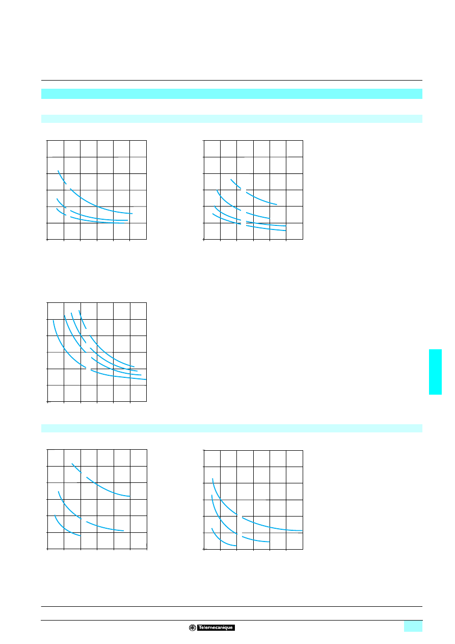
6/43
6
Curves
6
Interfaces
6
For discrete signals
Electromechanical interface modules
Electrical durability of contacts
Test conditions : in accordance with standard IEC 947-5-1 set up for rated control voltage, operating rate : 1800 cycles/hour. (0.5 Hz).
a.c. loads
AC-12 : control of resistive loads and isolated solid
state loads via optocoupler
cos
ϕ
≥
0.9
AC-13 : control of isolated solid state loads
via transformer
cos
ϕ
≥
0.65
AC-14 : control of weak electromagnetic loads of
electromagnets
≤
72 VA
make: cos
ϕ = 0.3
break: cos
ϕ = 0.3
AC-15 : control of electromagnetic loads of
electromagnets > 72 VA
make: cos
ϕ = 0.7
break: cos
ϕ = 0.4
1
24 V
2
48 V
3
127 V
4
230 V
d.c. loads
1
24 V
2
48 V
3
127 V
DC-12 : control of resistive loads and isolated solid
state loads via optocoupler
L/R
≤
1 ms
DC-13 : control of electromagnets
L/R
≤
2 x (Ue x Ie) in ms.
Ue: rated operating voltage
Ie: rated operating current
5
4
3
2
1
1
2
3
4
5
(A)
6
0
0
3
4
2
6
Operating cycles in millions
5
4
3
2
1
1
2
3
4
5
(A)
6
0
0
6
3
1
4
2
Operating cycles in millions
2
1
0,5
1
1,5
2
2,5
(A)
3
0
0
3
1
2
3
4
Operating cycles in millions
5
4
3
2
1
0
1
2
3
4
5
(A)
2
3
6
6
0
1
Operating cycles in millions
2
1
0,5
1
1,5
2
2,5
(A)
3
0
0
3
3
1
2
Operating cycles in millions
Presentation:
page 6/40
Characteristics:
pages 6/41 and 6/42
References:
page 6/44
Dimensions, schemes:
page 6/45
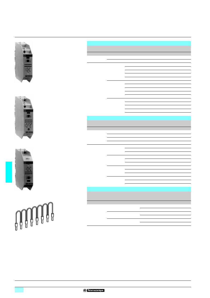
6/44
6
References
6
Interfaces
6
For discrete signals
Electromechanical interface modules
Control circuit : a.c. or d.c.
(1) Connection by screw-clamp.
(2) By green mechanical indicator light for contact(s) activated electrically or mechanically by
pressing the test button.
(3) By green LED illuminated when control signal is present.
(4) With polarization (+ on A1, - on A2).
Input interface modules
(1) (17.5 mm pitch)
Display
Composition
Control circuit
Enclosure
colour
Reference
Weight
V
kg
Mechanical (2)
1 N/O
a 230/240
Grey
ABR 1E101M
0.090
1 C/O
a 230/240
Grey
ABR 1E301M
0.090
Mechanical (2)
+ LED (3)
1 N/O
z 24
Grey
ABR 1E118B
0.095
z 48
Grey
ABR 1E118E
0.095
c 110...127 (4) Grey
ABR 1E112F
0.095
a 115...127
Grey
ABR 1E111F
0.095
a 230/240
Grey
ABR 1E111M
0.095
2 N/O
z 24
Grey
ABR 1E418B
0.095
z 48
Grey
ABR 1E418E
0.095
c 110...127(4)
Grey
ABR 1E412F
0.095
a 115...127
Grey
ABR 1E411F
0.095
a 230/240
Grey
ABR 1E411M
0.095
1 C/O
z 24
Grey
ABR 1E318B
0.095
z 48
Grey
ABR 1E318E
0.095
c 110...127(4)
Grey
ABR 1E312F
0.095
a 115...127
Grey
ABR 1E311F
0.095
a 230/240
Grey
ABR 1E311M
0.095
Output terminals-relays
(1)
(17.5 mm pitch)
Display
Composition
Control circuit
Enclosure
colour
Reference
Weight
V
kg
Mechanical (2)
1 N/O
c 24
Grey
ABR 1S102B
0.090
2 N/O
c 24
Grey
ABR 1S402B
0.090
1 C/O
c 24
Grey
ABR 1S302B
0.090
1 N/C + 1 N/O
c 24
Grey
ABR 1S602B
0.090
Mechanical (2)
+ LED (3)
1 N/O
z 24
Grey
ABR 1S118B
0.095
z 48
Grey
ABR 1S118E
0.095
a 115...127
Grey
ABR 1S111F
0.095
2 N/O
z 24
Grey
ABR 1S418B
0.095
z 48
Grey
ABR 1S418E
0.095
a 110
Grey
ABR 1S411F
0.095
1 C/O
z 24
Grey
ABR 1S318B
0.095
z 48
Grey
ABR 1S318E
0.095
a 110
Grey
ABR 1S311F
0.095
1 N/C + 1 N/O z 24
Grey
ABR 1S618B
0.095
z 48
Grey
ABR 1S618E
0.095
a 110
Grey
ABR 1S611F
0.095
Commoning links
Description
For common
Colour
Distance
between
cable ends
Reference
Weight
cm
kg
Commoning
links in modules
8 x 1 mm
2
Coil
White
12
ABF C08R12W
0.020
2
ABF C08R02W
0.010
a
Red
12
ABF C08R12R
0.020
2
ABF C08R02R
0.010
c
Blue
12
ABF C08R12B
0.020
2
ABF C08R02B
0.010
81
626
4
ABR 1E101M
81
821
5
ABR 1E318B
81
6265
ABR 1S102B
8162
73
ABF C08R
ppp
Presentation:
page 6/40
Characteristics:
pages 6/41 and 6/42
Curves:
page 6/43
Dimensions, schemes:
page 6/45
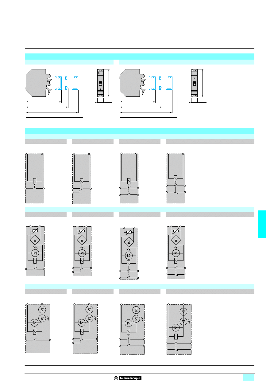
6/45
6
Dimensions,
schemes
6
Interfaces
6
For discrete signals
Electromechanical interface modules
Dimensions
ABR 1E
ABR 1S
Schemes
c 24 V or a 230 V interfaces with mechanical indication
1 N/O
1 C/O
2 N/O
1 N/C + 1 N/O
z 24 V or z 48 V interfaces with mechanical indication + LED
1 N/O
1 C/O
2 N/O
1 N/C + 1 N/O
c / a 110 V or a 230 V interfaces with mechanical indication + LED
1 N/O
1 C/O
2 N/O
1 N/C + 1 N/O
78
75
70,5
17,5
74
63
78
75
70,5
17,5
74
63
A2
13
14
A1
11
14
12
A2
A1
13
14
23
24
A2
A1
23
24
11
12
A2
A1
A1
13
14
A2
11
14
12
A2
A1
13
14
23
24
A2
A1
23
24
11
12
A1
A2
13
14
A1
(
+
)
A2
11
14
12
A1
(
+
)
A2
13
14
23
24
A1
(
+
)
A2
23
24
11
12
A1
(
+
)
A2
Presentation:
page 6/40
Characteristics:
pages 6/41 and 6/42
Curves:
page 6/43
References:
page 6/44
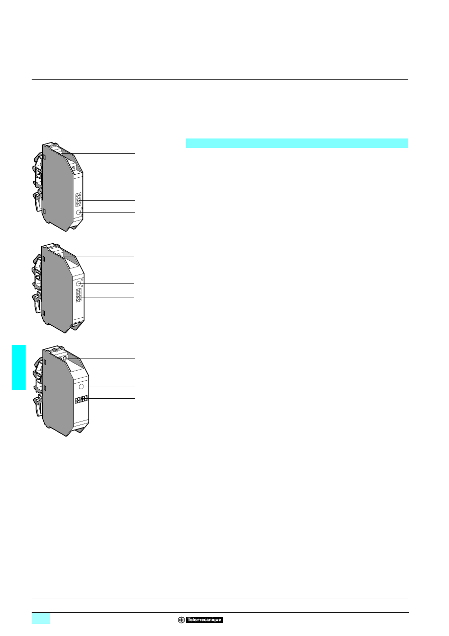
6/46
6
Presentation
6
Interfaces
6
For discrete signals
Slim electromechanical interface modules
ABR-2 electromechanical interface modules complement the ABR-1 range.
They are characterised by micro relay technology which allows reduced dimensions
and very low switching levels (TTL, HCMOS, analogue signals).
The ABR-2 family is in the form of slim compact modules, 9.5 mm wide for input
interface modules, 12 mm wide for output interface modules and 17.5 mm wide for
very low level switching products.
The ABR-2 comprises 3 families :
Input interfaces (9.5 mm pitch)
Input interfaces are designed for switching input signals to a processor and are
characterized by their high degree of contact reliability : less than 1 fault per
100 million operating cycles at c 17 V, 5 mA.
An assured immunity to current leakages
≤ 2 mA, and a wide coil voltage range
(0.7 to 1.25 Un).
Output interfaces (12 mm pitch)
Output interfaces are designed for the control of preactuators (contactors, solenoid
valves, etc) for signalling devices (indicators lamps, audible warnings etc). They are
characterized by a high switching capacity and an assured immunity to current
leakages
≤ 2 mA. A lower cost version without LED signalling is available.
Low level switching input and output interfaces (17.5 mm pitch)
with 1 C/O contact.
These interfaces are designed for switching logic (TTL or HCMOS) and analogue
signals.
Warning : never switch inductive loads with this type of interface.
The front panel of the ABR-2 electromechanical interface module comprises :
1
LED indicating the control signal state
2
Channel identification : 5 individual characters for AB1-R/G or 1 AB1-SA2
marker tag
3
Connection by screw clamp terminal enabling easy attachment of 2 wires per
terminal. The layout of the connection terminals for both families (input and output)
is designed for rational wiring and a clear separation between the incoming
(processing) and outgoing (power and process control) circuits.
Description
3
2
1
3
2
1
3
2
1
Characteristics:
pages 6/47 and 6/48
Curves:
page 6/49
References:
page 6/50
Dimensions, schemes:
page 6/51
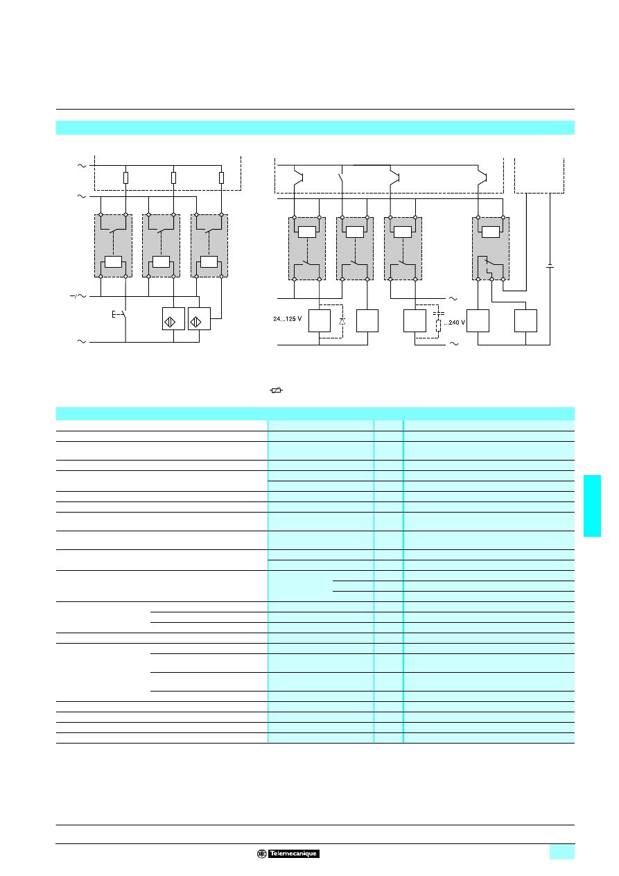
6/47
6
Characteristics
6
Interfaces
6
For discrete signals
Slim electromechanical interface modules
(1) Essential on inductive loads (can be replaced with peak limiter
).
Examples of applications with PLCs
–
/
+
/
+
/
13
14
13
14
13
14
A1
A2
A1
A2
A1
A2
PLC
Positive logic discrete inputs
Pushbuttons
Series contacts
2-wire
sensors
3-wire
sensors
ABR 2Epppp
Process
power
supply
Processing
power
supply
–
+
–
+
A1
A2
(1)
(1)
C1
A1
A2
A1
A2
13
14
13
14
13
14
A1
A2
12
14
C2
OV
11
PLC
Positive logic transistor (or relay) outputs
PLC
Analogue inputs
Channel X
Analogue
sensors
ABR 2Spppp
ABR 2SB12B
Environment
Conforming to standards
IEC 947-5-1
Product certifications
UL, CSA, BV, LROS, DNV
Degree of protection
Conforming to IEC 529
(protection against direct contact)
IP 20
Protective treatment
“TC”
Flame resistance
Conforming to IEC 695-2-1
Incandescent wire
°C
960
Conforming to UL 94
V0
Shock resistance
Conforming to IEC 68-2-27
Semi-sinusoidal waves 11 ms
30 gn
Vibration resistance
Conforming to IEC 68-2-6
10…150 Hz
3 gn
Resistance to electrostatic
discharges
Conforming to IEC 801-2
Level 3
kV
8
Resistance to
electromagnetic fields
Conforming to IEC 801-3
Level 3 ; 27…1000 MHz
V/m
10
Resistance to rapid
transients
Conforming to IEC 801-4
Level 3
On power supply
kV
2
On I/O
kV
1
Resistance to shock
waves
Conforming to IEC 947-1
Waveform
1.2/50
μs ; 0.5 J
U < 50 V
kV
0.5
U < 150 V
kV
1.5
U < 300 V
kV
2.5
Cross-sections which
may be connected
Flexible cable with no cable end
1 or 2-wire
mm
2
0.6…2.5
Flexible cable with cable end
1 or 2-wire
mm
2
0.34…2.5
Rigid cable
1-wire
mm
2
0.27…4
Operating position
Any
Ambient air temperature
Unrestricted operation
°C
- 5…+ 40
Operation from 0.85...1.1 Us
(assigned voltage)
°C
- 5…+ 55
Operation restricted to Us
(assigned voltage)
°C
- 25…+ 70 (2)
Storage
°C
- 40…+ 80
Operating altitude
m
≤ 3000
Installation category
Conforming to IEC 947-1
II
Degree of pollution
Conforming to IEC 947-1
2
Mounting
Standard rails
5
1 4
(2) Leave space of 8 mm between ABR-2S1
ppp
for an ambient temperature
≥ 55 °C
Presentation:
page 6/46
Curves:
page 6/49
References:
page 6/50
Dimensions, schemes:
page 6/51
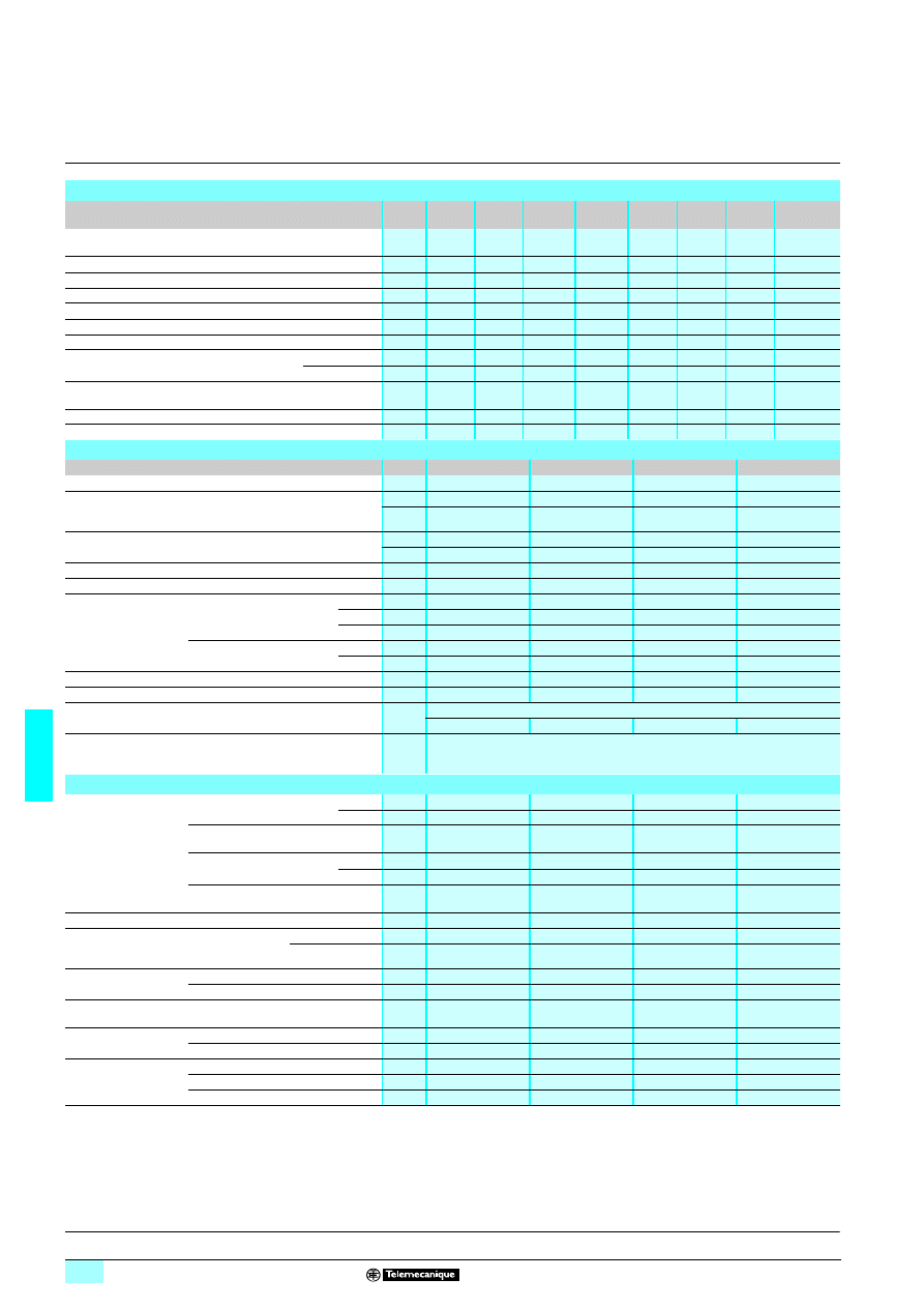
6/48
6
Characteristics
(continued)
6
Interfaces
6
For discrete signals
Slim electromechanical interface modules
(1) Do not switch inductive loads.
Control circuit characteristics
(40°C ambient temperature)
Type of interface
ABR
2E112B
ABR
2E112E
ABR
2E115F
ABR
2E116F
ABR
2E111M
ABR
2S112B
ABR
2S102B
ABR
2pB312B (1)
Rated voltage (Us)
V
c 24
c 48
z
115…127
z
120...127
a
230...240
c 24
c 24
c 24
Current frequency
Hz
–
–
50
60
50/60
–
–
–
Energization threshold
V
16.9
37.3
93
97
186
16.9
14.5
16.9
Maximum operating voltage
V
28.8
57.6
140
140
264
28.8
28.8
28.8
Maximum drop-out voltage (Uo)
V
3.8
8.5
25.4
25.4
48
3.8
2
3.8
Maximum current (at Us)
mA
19.5
11
14
16
15
28
18
23
Minimum holding current
mA
2
2
2.5
2.5
2.5
2
1.3
2
Maximum dissipated power (at Us)
50 Hz
W
–
–
0.66
–
0.54
–
–
–
60 Hz
W
0.45
0.52
–
0.73
0.77
0.64
0.43
0.55
Disappearance of voltage
maximum time up to which contact is maintained
ms
1
1
10
10
10
1
5
1
Display of control circuit by LED
Yes
Yes
Yes
Yes
Yes
Yes
No
Yes
Built-in protection reversed polarity
Yes
Yes
–
–
–
Yes
Yes
Yes
Contact characteristics
(40°C ambient temperature)
Type of interface
ABR 2Epppp
ABR 2S112B
ABR 2S102B
ABR 2pB312B (1)
Composition
1 N/O
1 N/O
1 N/O
1 C/O
Maximum rated
operating voltage
(Ue max)
Conforming to IEC 947-5-1
a V
127
230
230
48
c V
100
120
120
48
Maximum switching voltage
a V
140
250
250
60
c V
125
150
150
60
Operating current frequency
Hz
50/60
50/60
50/60
50/60
Thermal current Ith
Conforming to IEC 947-1
A
1
5
5
0.05
Rated operating
current (Ie)
for 1 million operating
cycles
Conforming to IEC 947-5-1
Ue max
AC12
A
1
3
3
–
AC14
A
0.5
1
1
–
AC15
A
0.5
1
1
–
Conforming to IEC 947-5-1
Ue : c 24 V
DC12
A
1
1.7
1.7
–
DC13
A
1
1.5
1.5
–
Minimum switching current
mA
1
5
5
0.01
Minimum switching voltage
V
5
5
5
0.01
Protection against
short-circuits
For Ik
≤ 1 kA (a) and ≤ 100 A (c)
Type and value of recommended fuse
Type : quick-blow fuse with high breaking capacity
A
2
6.3
6.3
0.4
Low level contact
reliability (17 V, 5 mA)/
ABR-2pB (30 mV, 10 µA)
Number of faults
per "n" million operating cycles
1 per 100 million
Other characteristics
Maximum operating
time
at Us (bounce included)
Between energization of coil
and closing of N/O contact
c
ms
10
10
10
6
a
ms
30
–
–
–
Between energization of coil and
opening of N/C contact
ms
–
–
–
6
Between de-energization of coil
and opening of N/O contact
c
ms
6
12
5
6
a
ms
30
–
–
–
Between de-energization of coil and
closing of N/C contact
ms
–
–
–
6
Maximum duration of bounce
ms
5
5
5
2
No make before break
guaranteed between
“N/C” and “N/O” contacts
Maximum make
before break or break
before make time
On energization
ms
–
–
–
5
On de-energization ms
–
–
–
2
Maximum operating
rate
At no-load
Hz
10
10
10
10
At Ie
Hz
0.5
0.5
0.5
–
Mechanical durability
in millions of operating cycles
20
10
10
20
Rated insulation
voltage
Conforming to IEC 947-1
V
300
300
300
300
Conforming to VDE 0110 group C
V
250
250
250
250
Insulation test voltage
for 1 min
Coil circuit/contact circuits
kV rms 2
4
4
1.5
Wired interface/earth
kV rms 2.5
2.5
2.5
2.5
Between open contacts
kV rms 0.75
1
1
1
Presentation:
page 6/46
Curves:
page 6/49
References:
page 6/50
Dimensions, schemes:
page 6/51
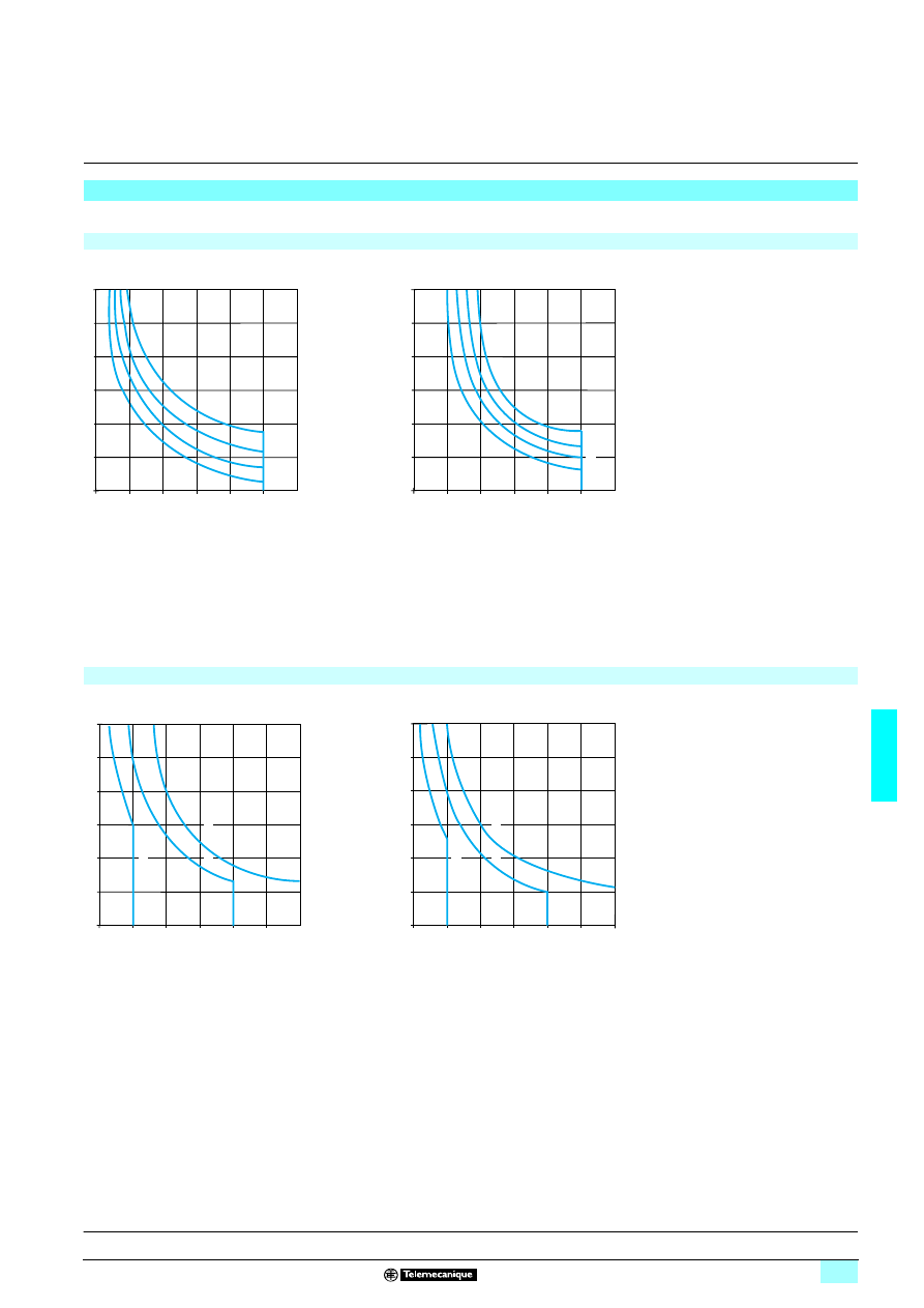
6/49
6
Curves
6
Interfaces
6
For discrete signals
Slim electromechanical interface modules
Electrical durability of contacts
(ABR 2S)
Test conditions : in accordance with standard IEC 947-5-1 set up for rated control voltage.
a.c. loads
1
24 V
2
48 V
3
115 V
4
230 V
AC12 : control of resistive loads and isolated solid state
loads via optocoupler
cos
ϕ ≥ 0.9
AC14 : control of weak electro-magnetic loads of
electro-magnets
≤ 72 VA
make : cos
ϕ = 0.3
break : cos
ϕ = 0.3
AC15 : control of electro-magnetic loads of
electro-magnets > 72 VA
make : cos
ϕ = 0.7
break : cos
ϕ = 0.4
d.c. loads
1
24 V
2
48 V
3
115 V
DC12 : control of resistive loads and isolated solid state
loads via optocoupler
L/R
≤ 1 ms
DC13 : control of electro-magnets
L/R
≤ 2 x (Ue x Ie) in ms.
Ue : rated operating voltage
Ie : rated operating current
(with a load protection diode)
5
4
3
2
1
1
2
3
4
5
(A)
6
0
0
3
4
2
6
1
Operating cycles in millions
2
1
0,5
1
1,5
2
2,5
(A)
3
0
0
3
2
4
3
1
Operating cycles in millions
2
1
0,5
1
1,5
2
2,5
(A)
3
0
0
3
1
2
3
Operating cycles in millions
2
1
0
0,5
1
1,5
2
2,5
(A)
2
3
3
3
0
1
Operating cycles in millions
Presentation:
page 6/46
Characteristics:
pages 6/47 and 6/48
References:
page 6/50
Dimensions, schemes:
page 6/51
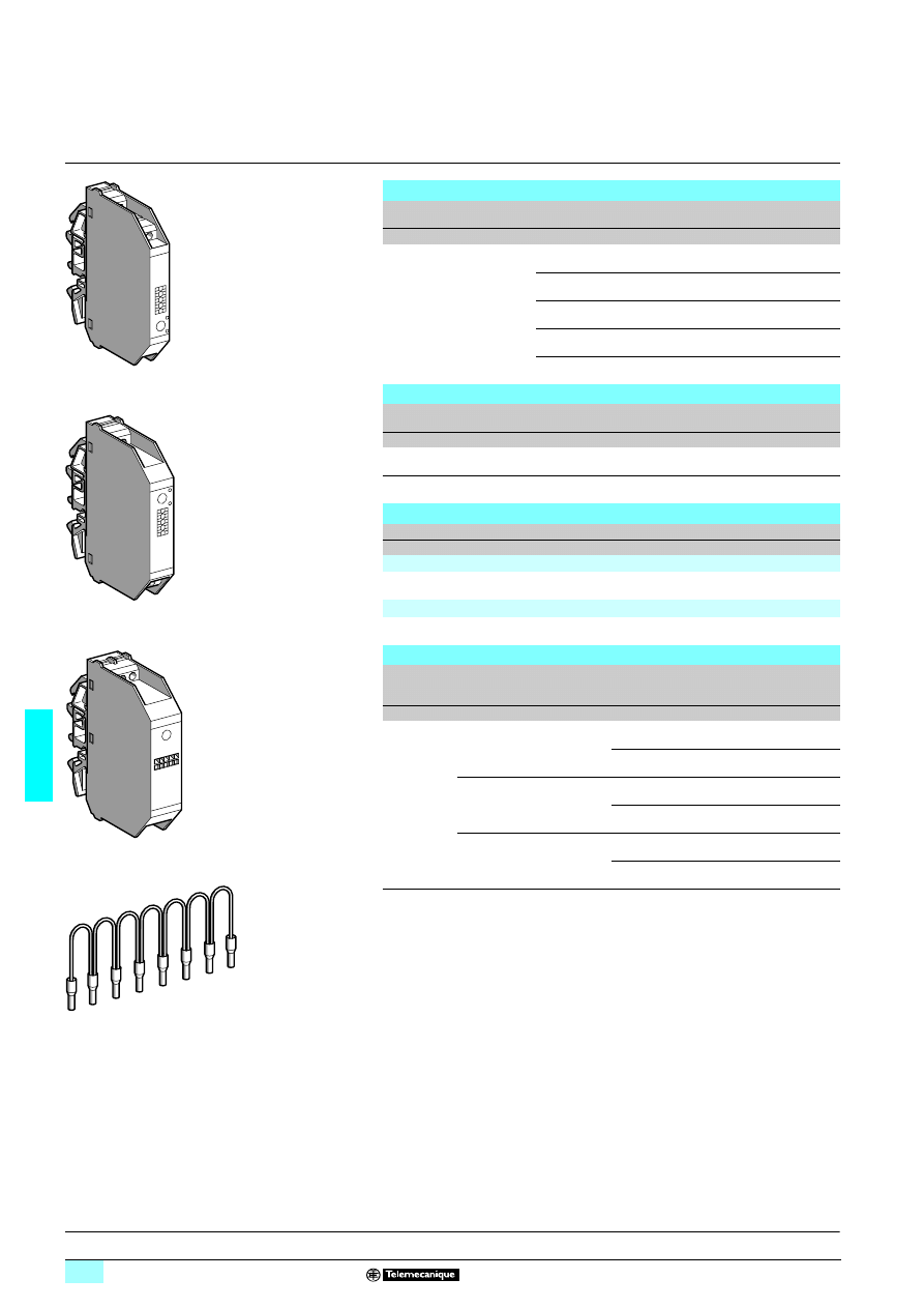
6/50
6
References
6
Interfaces
6
For discrete signals
Slim electromechanical interface modules
Control circuit : a.c. or d.c.
(1) Do not switch inductive loads.
Input modules
(9.5 mm pitch)
Indication
Composition
Control circuit
Sold in
lots of
Unit
reference
Weight
V
kg
With LED
1 N/C
c 24
5
ABR 2E112B
0.032
c 48
5
ABR 2E112E
0.032
a 115...127 (50 Hz)
5
ABR 2E115F
0.035
a 120...127 (60 Hz)
5
ABR 2E116F
0.035
a 230...240 (50/60 Hz)
5
ABR 2E111M
0.036
Output modules
(12 mm pitch)
Indication
Composition
Control circuit
Sold in
lots of
Unit
reference
Weight
V
kg
Without
1 N/C
c 24
5
ABR 2S102B
0.040
With LED
1 N/C
c 24
5
ABR 2S112B
0.041
Modules for very low level switching
(17.5 mm pitch)
Indication
Composition
Control circuit
Reference
Weight
V
kg
Input
With LED
1 C/O (1)
c 24
ABR 2EB312B
0.048
Output
With LED
1 C/O (1)
c 24
ABR 2EB312B
0.048
Flexible comb accessories
Description
For common
Colour
Distance
between
cable ends
Reference
Weight
cm
kg
Flexible
comb
modularity
8 x 1 mm
2
Coil
White
12
ABF C08R12W
0.020
2
ABF C08R02W
0.010
a
Red
12
ABF C08R12R
0.020
2
ABF C08R02R
0.010
c
Blue
12
ABF C08R12B
0.020
2
ABF C08R02B
0.010
81
636
2
ABR 2E112B
8
1636
3
ABR 2S112B
8163
64
ABR 2EB112B
816
365
ABF C08R
ppp
Presentation:
page 6/46
Characteristics:
pages 6/47 and 6/48
Curves:
page 6/49
Dimensions, schemes:
page 6/51
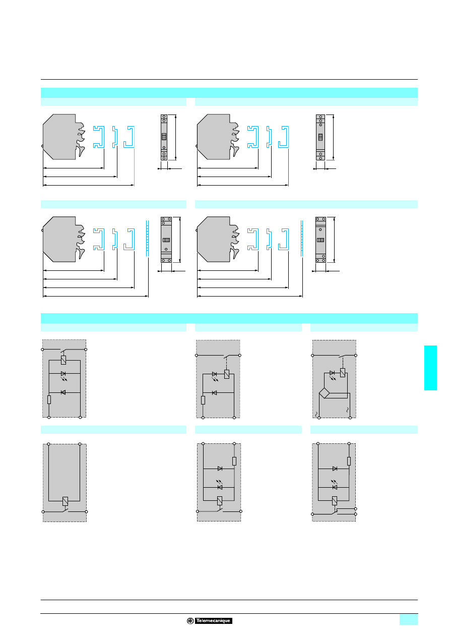
6/51
6
Dimensions,
schemes
6
Interfaces
6
For discrete signals
Slim electromechanical interface modules
Dimensions
ABR 2E11pp
ABR 2S1p2B
ABR 2EB312B
ABR 2SB312B
Circuit diagrams
ABR 2E112B (c 24 V)
ABR 2E112E (c 48 V)
ABR 2E11pF/M (a 115...240 V)
ABR 2S102B (c 24 V)
ABR 2S112B (c 24 V)
ABR 2pB312B (c 24 V)
78
75
70,5
9,5
74
78
75
70,5
12
74
78
75
70,5
63
17,5
74
78
75
70,5
63
17,5
74
+
A1
–
A2
13
14
+
A1
–
A2
14
13
A1
–
A2
13
14
13
14
+
A1
–
A2
13
14
+
A1
–
A2
14
11
12
+
A1
–
A2
Presentation:
page 6/46
Characteristics:
pages 6/47 and 6/48
Curves:
page 6/49
References:
page 6/50
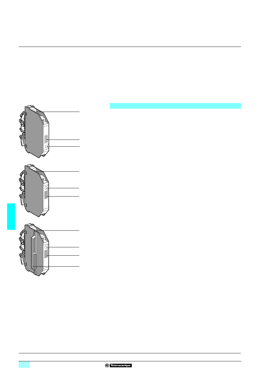
6/52
6
Presentation
6
Interfaces
6
For discrete signals
Slim solid-state interface modules
The ABS-2 solid-state interface relays are supplied in the form of compact modules
which appear identical to the ABR-2 electromechanical family.
They are designed for interfacing discrete digital control signals exchanged within an
automated system between the processor (PLC, numerical controller, etc) and the
other components (contactors, solenoid valves, indicator lamps, proximity sensors,
etc).
They are suitable for use in equipment which requires the benefits of electronic
technology : a high operating rate, virtually unlimited durability, silent operation, etc.
These products are notable for their high performance and excellent adaptation to
industrial environments, ensured by the fact that they conform to the most recent IEC
standards.
The ABS-2 range comprises 2 families :
Input interfaces
The 9.5 mm wide input interfaces are designed for switching input signals to
processors. They offer a wide choice of electrical isolation between signals due to
the wide range of input voltages from c 5 V to a 230 V.
Output interfaces
Output interfaces are designed for the control of preactuators (contactors, solenoid
valves, etc) for the signalling devices (indicator lamps, audible warnings, etc).
Two widths are available, 9.5 and 17.5 mm, depending on the switched current.
The 17.5 mm version comprises a 9.5 mm interface and an integrated 8 mm spacer.
This device can, with its increased ventilation, switch high levels of currents.
The front panel of the ABS-2 slim solid-state interface modules comprises:
1
LED indicating the state of the control signal.
2
Channel identification : 5 individual characters for AB1-/G or one AB1-SA2 marker
tag.
3
Connection by screw clamp terminal enabling easy attachment of 2 wires per
terminal.
The layout of the connection terminals for both families (input and output) is
designed for rational wiring and a clear separation between the incoming
(processing) and outgoing (power and process control) circuits.
4
Integrated spacer.
Composition
3
2
1
8
1638
0
3
2
1
81
6378
3
2
1
4
8163
79
Characteristics:
pages 6/53 to 6/55
References, curves:
page 6/56
Dimensions, schemes:
page 6/57
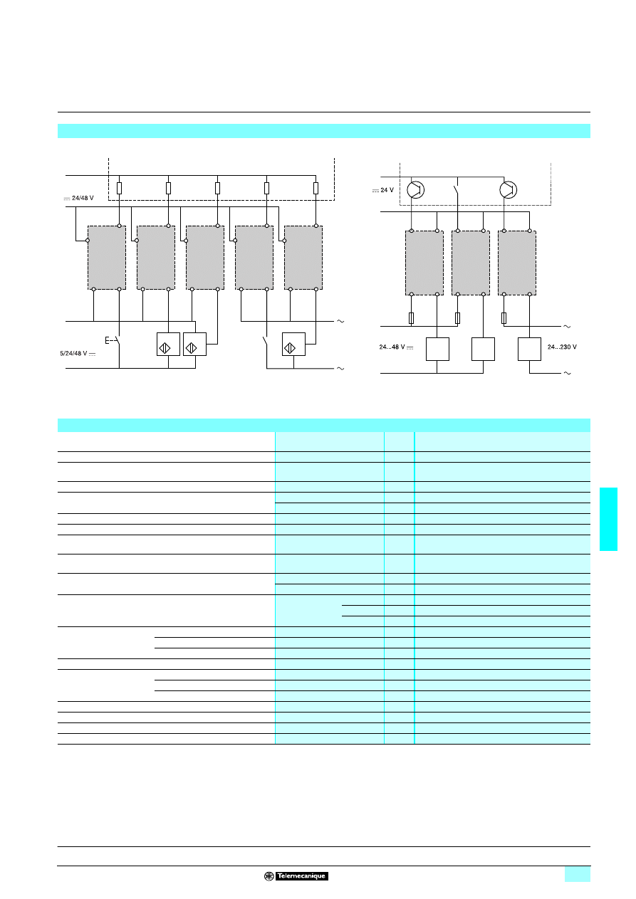
6/53
6
Characteristics
6
Interfaces
6
For discrete signals
Slim solid-state interface modules
Examples of applications with PLCs
Interfacing PLC discrete inputs
Interfacing PLC discrete outputs
–
+
–
+
14
13
14
13
ABS - 2E
13
14
PNP
115/
230 V
13
14
13
14
A1
A2
A1
A2
A1
A2
A1
A2
A1
A2
PLC
Positive logic discrete inputs
Pushbuttons
Series contacts
2-wire
sensors
3-wire
sensors
Pushbuttons
Series contacts
2-wire
sensors
Process
power supply
Processing
power supply
–
+
–
+
A1
A2
A1
A2
A1
A2
ABS - 2S
F
13
14
13
14
13
14
PLC
Positive logic transistor (or relay) outputs
Environment
Conforming to standards
IEC 947-5-1
Draft standard IEC 17 B secretariat 200
Product certifications
UL, CSA, BV, LROS, DNV
Degree of protection
Conforming to IEC 529
(protection against direct contact)
IP 20
Protective treatment
“TC”
Flame resistance
Conforming to IEC 695-2-1
Incandescent wire
°C
960
Conforming to UL 94
V0
Shock resistance
Conforming to IEC 68-2-27
Semi-sinusoidal waves 11 ms
30 gn
Vibration resistance
Conforming to IEC 68-2-6
10…150 Hz
5 gn
Resistance to electrostatic
discharges
Conforming to IEC 801-2
Level 3
kV
8
Resistance to
electromagnetic fields
Conforming to IEC 801-3
Level 3 ; 27…1000 MHz
V/m
10
Resistance to rapid
transients
Conforming to IEC 801-4
Level 3
On power supply
kV
2
On I/O
kV
1
Resistance to shock
waves
Conforming to IEC 947-1
Waveform
1.2/50 ms ; 0.5 J
U < 50 V
kV
0.5
U < 150 V
kV
1.5
U < 300 V
kV
2.5
Cross-sections which
may be connected
Flexible cable with no cable end
1 or 2-wire
mm
2
0.6…2.5
Flexible cable with cable end
1 or 2-wire
mm
2
0.34…2.5
Rigid cable
1-wire
mm
2
0.27…4
Operating position
Any
Ambient air temperature
around the device
Unrestricted operation
°C
- 5…+ 55
Operation at Us
°C
- 25…+ 70
Storage
°C
- 40…+ 80
Operating altitude
m
≤ 300
Installation category
Conforming to IEC 947-1
II
Degree of pollution
Conforming to IEC 947-1
2
Mounting
Standard rails
5
1 4
Presentation:
page 6/52
References, curves:
page 6/56
Dimensions, schemes:
page 6/57
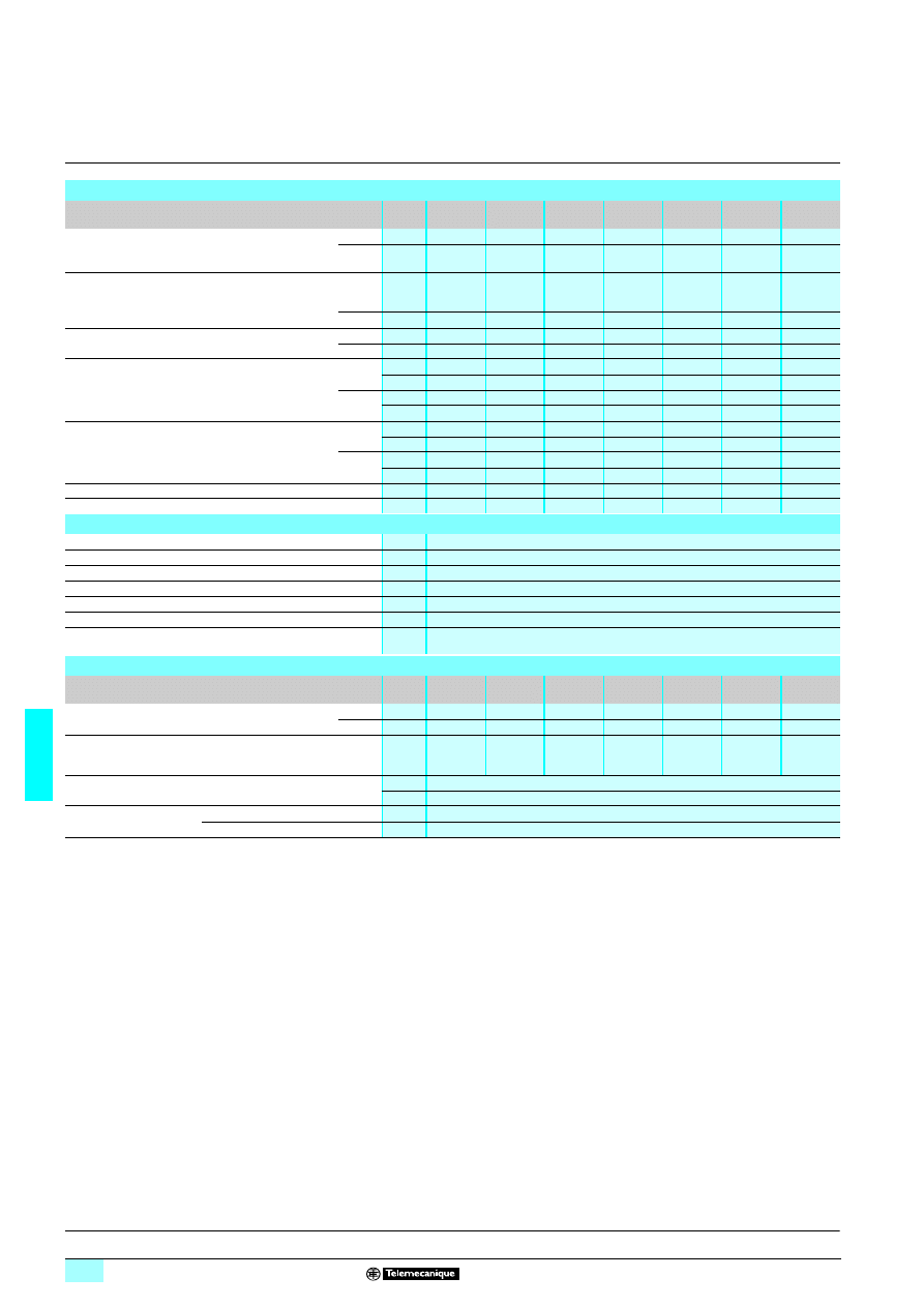
6/54
6
Characteristics
(continued)
6
Interfaces
6
For discrete signals
Slim solid-state interface modules
Control circuit characteristics
(55°C ambient temperature)
Type of interface
ABS
2EC01EA
ABS
2EC01EB
ABS
2EC01EE
ABS
2EA01EF
ABS
2EA02EF
ABS
2EA01EM
ABS
2EA02EM
Rated voltage Us
c
V
5
24
48
–
–
–
–
a
V
–
–
–
115/127
50 Hz
120/127
60 Hz
230/240
50 Hz
230/240
60 Hz
Maximum voltage
c
V
Negative
logic
6 (TTL)
28.8
57.6
–
–
–
–
a
V
–
–
–
140
140
264
264
Maximum current at Us
c
mA
13.6
12
10.5
–
–
–
–
a
mA
–
–
–
14
17
12.5
15
State 1 assured
c
V
3.75
16.9
36
–
–
–
–
mA
4.5
7.7
7.5
–
–
–
–
a
V
–
–
–
86.3
90
173
173
mA
–
–
–
8.4
9.7
7.9
9.3
State 0 assured
c
V
2
5.6
10.8
–
–
–
–
mA
0.09
2
2
–
–
–
–
a
V
–
–
–
25.4
25.4
48
48
mA
–
–
–
2.5
2.5
2.5
2.5
State 1 display
Yes
Yes
Yes
Yes
Yes
Yes
Yes
Internal protection reversed polarity
Yes
Yes
Yes
–
–
–
–
Output circuit characteristics
Rated operating voltage Ue
c
V
5...48
Min/max voltage
c
V
2/60
Min/max current switched
mA
1/50
Maximum residual current at state 0
mA
0.1
Maximum volt drop at state 1
V
1
Internal protection
Reversed polarity
External protection
Against short-circuits for Ik
≤ 100 A (c)
Quick-blow fuse, ref. : HA21 0.25 A or equivalent
Other characteristics
Type of interface
ABS
2EC01EA
ABS
2EC01EB
ABS
2EC01EE
ABS
2EA01EF
ABS
2EA02EF
ABS
2EA01EM
ABS
2EA02EM
Time delay characteristics
Response time max Ue
≤ 30 V Ie ≥ 5 mA
0 V 1
ms
0.05
0.05
0.05
10
10
10
10
1 V 0
ms
0.4
0.4
0.4
20
20
20
20
Maximum switching rate
Duty cycle 50 %
Ue
≤ 30 V Ie ≥ 5 mA
Hz
1000
1000
1000
25
25
25
25
Rated insulation voltage
Conforming to IEC 947-1 : 300 V
Conforming to VDE 0110 : 250 V group C
Insulation test voltage
for 1 minute
I/O
kVrms
4
Wired interface/earth
kVrms
2.5
Presentation:
page 6/52
References, curves:
page 6/56
Dimensions, schemes:
page 6/57
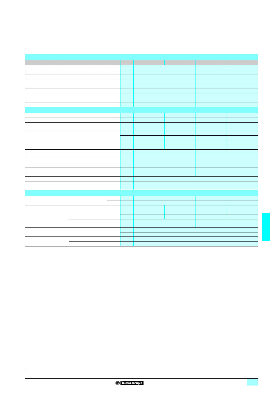
6/55
6
Characteristics
(continued)
6
Interfaces
6
For discrete signals
Slim solid-state interface modules
(1) See temperature derating curves.
Control circuit characteristics
(55°C ambient temperature)
Type of interface
ABS 2SC01EB
ABS 2SC02EB
ABS 2SA01MB
ABS 2SA02MB
Rated voltage Us
c
V
24
24
Maximum voltage
V
28.8
28.8
Maximum current at Us
mA
12
13.6
State 1 assured
V
16.9
16.9
mA
7.7
8.3
State 0 assured
V
5.6
5.3
mA
2
2
State 1 display
Yes
Yes
Internal protection reversed polarity
Yes
Yes
Output circuit characteristics
Rated operating voltage Ue
V
c 5...48
c 5...48
a 24...240
a 24...240
Maximum voltage
V
c 57.6
c 57.6
a 264
a 264
Maximum continuous current (Ith) (1)
at 40 °C
A
2
3
2.3
3
Rated operating voltage (Ie)
Conforming to IEC 947-5-1
Single/touching product
at 55 °C vertical position
A
DC12
1.5/0.9
2.5/2.2
AC12
1.9/0.5
2.1/1.5
A
DC13
1.5/0.9
2.5/2.2
AC13
1.6/0.5
1.6/1.5
A
DC14
0.6/0.6
0.6/0.6
AC14
1.6/0.5
1.6/1.5
A
–
–
–
AC15
1/0.5
1/1
Minimum current
c/a
mA
1
10
Maximum residual current
c/a
mA
1
2.5
Maximum volt drop
V
1.5
3 (Ie
≥ 10 mA)
1.5 (Ie
≥ 100 mA)
“0 crossing” voltage
V
–
50 peak
Solid-state dV/dt
V/
μs
–
500
Internal protection
Reversed polarity
External protection
Against short-circuits for Ik
≤ 1 kA (a) and ≤ 100 A (c)
Quick-blow fuse with high breaking capacity: 3.15 A
Other characteristics
Maximum response time
at Ie
≥ 10 mA
0 V 1
ms
0.05
10 (50 Hz) ; 8 (60Hz)
1 V 0
ms
0.6
10 (50 Hz) ; 8 (60Hz)
Maximum switching rate
At 55 °C ; at Ie: module alone
duty cycle 40 %
Hz
DC13
6
6
AC13
0.6
0.7
Hz
DC14
1
3
AC14
0.6
0.7
Hz
–
–
–
AC15
0.6
0.7
On resistive load
duty cycle 50 %
Hz
700
50
Rated operating voltage
Conforming to IEC 947-1 : z 300 V
Conforming to VDE 0110 : 250 V group C
Rated Insulation voltage
for 1 minute
I/O
kVrms
4
Wired interface/earth
kVrms
2.5
Presentation:
page 6/52
References, curves:
page 6/56
Dimensions, schemes:
page 6/57
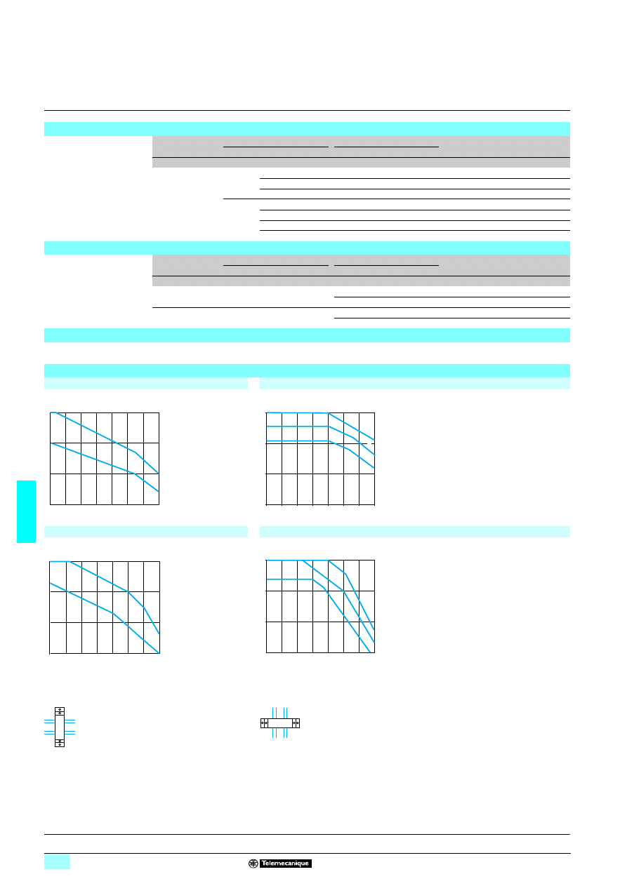
6/56
6
References,
curves
6
Interfaces
6
For discrete signals
Slim solid-state interface modules
Solid-state input modules
Width
Input circuit
Output circuit
Sold in
lots of
Unit
reference
Weight
Current
Nominal voltage
Current
Nominal voltage
mm
V
V
kg
9.5
c
5
c
5…48
5
ABS 2EC01EA
0.029
24
c
5…48
5
ABS 2EC01EB
0.029
48
c
5…48
5
ABS 2EC01EE
0.029
a
115…127 (50 Hz)
c
5…48
5
ABS 2EA01EF
0.032
120…127 (60 Hz)
c
5…48
5
ABS 2EA02EF
0.032
230…240 (50 Hz)
c
5…48
5
ABS 2EA01EM
0.033
230…240 (60 Hz)
c
5…48
5
ABS 2EA02EM
0.033
Solid-state output modules
Width
Input circuit
Output circuit
Sold in
lots of
Unit
reference
Weight
Current
Nominal voltage
Current
Nominal voltage
mm
V
A
V
kg
9.5
c
24
c 2
24…48
5
ABS 2SC01EB
0.034
a 2.3
24…230
5
ABS 2SA01MB
0.034
17.5
c
24
c 3
24…48
1
ABS 2SC02EB
0.043
a 3
24…230
1
ABS 2SA02MB
0.044
Accessories
For connecting commons, use ABF C08ppp flexible combs (Please consult your Regional Sales Offices).
Temperature derating curve for solid-state output modules Uc = Us = c 24 V
ABS 2SC01EB d.c.
ABS 2SC02EB d.c.
ABS 2SA01MB a.c.
ABS 2SA02MB a.c.
1
Vertical module alone or adjacent to modules with
low heat dissipation.
2
Horizontal module alone or adjacent to modules with
low heat dissipation.
3
Vertical module mounted with 2 modules with
identical heat dissipation on both sides.
4
Horizontal module mounted with 2 modules with
identical heat dissipation on both sides.
10
20
30
40
50
60
70
1
2
3
1/2
0
0
3/4
Ie (A)
T °C ambient
10
20
30
40
50
60
70
1
2
3
1/2
0
0
4
3
Ie (A)
T °C ambient
10
20
30
40
50
60
70
1
2
3
1/2
0
0
3/4
Ie (A)
T °C ambient
10
20
30
40
50
60
70
1
2
3
1/2
0
0
4
3
Ie (A)
T °C ambient
Presentation:
page 6/52
Characteristics:
pages 6/53 to 6/55
Dimensions, schemes:
page 6/57
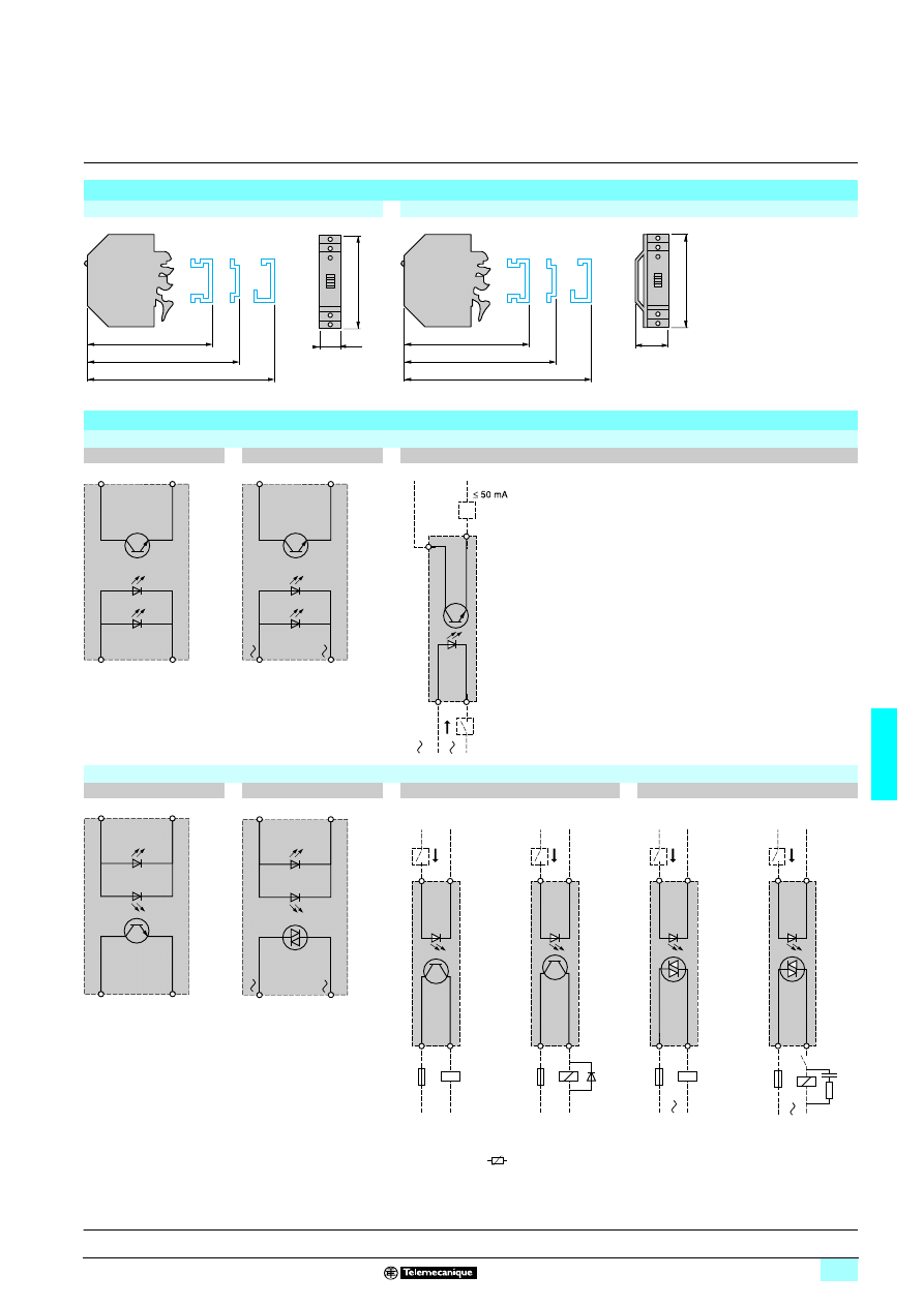
6/57
6
Dimensions,
schemes
6
Interfaces
6
For discrete signals
Slim solid-state interface modules
Dimensions
ABS 2E/ABS 2Sp01pp
ABS 2Sp02pp
Circuit diagrams
Solid-state input modules
ABS 2ECpppp
ABS 2EApppp
ABS 2Epppp
Solid-state output modules
ABS 2SC0pEB
ABS 2SA0pMB
ABS 2SC0pEB
ABS 2SA0pMB
F: fuse DF1 SS133.2
(1) or peak limiter
78
75
70,5
74
9,5
78
75
70,5
17,5
74
+
A1
–
A2
+
13
–
14
A1
A2
+
13
–
14
14
13
A2
A1
+
–
5…48 V
+
–
+
13
–
14
+
A1
–
A2
13
14
+
A1
–
A2
14
13
A2
A1
+
–
+
–
– F
5-24 V
Resistive load
14
13
A2
A1
+
–
+
–
– F
5-24 V
(1)
Inductive load
14
13
A2
A1
+
–
– F
5-24 V
Resistive load
14
13
A2
A1
+
–
– F
5-24 V
(1)
Inductive load
Presentation:
page 6/52
Characteristics:
pages 6/53 to 6/55
References, curves:
page 6/56
Wyszukiwarka
Podobne podstrony:
ch6 030702
Ch6 E4
Ch6 Pgs219 242
ch6
ch6
cisco2 ch6 focus B5BPVOCQFZHFLVQCHJBGE44PTKTAEUAFQWKNNWQ
Beginning smartphone development CH6
cisco2 ch6 vocab IWY4ZIDR4ERMF3TLNEL6RP6FA7AK2SQL7RQWQBY
ch6
Ch6 E7
ch6 zajzzv3woe5iy6niljqfqtsxijfkp7hzz7zp5wi ZAJZZV3WOE5IY6NILJQFQTSXIJFKP7HZZ7ZP5WI
Ch6 Parametric Sketches
Ch6 SocialImplicationsOfForestEnergyProduction
Ch6 E2
Ch6 E6
Ch6
cisco2 ch6 concept JJMG4YPKD5AN442ISO6S4CWJEQFD2QRRMFYLNWI
więcej podobnych podstron