
1
Embedded Systems Design: A
Unified Hardware/Software
Introduction
Chapter 6 Interfacing

2
Embedded Systems Design: A Unified
Hardware/Software Introduction,
(c) 2000
Vahid/Givargis
Outline
• Interfacing basics
• Microprocessor interfacing
– I/O Addressing
– Interrupts
– Direct memory access
• Arbitration
• Hierarchical buses
• Protocols
– Serial
– Parallel
– Wireless

3
Embedded Systems Design: A Unified
Hardware/Software Introduction,
(c) 2000
Vahid/Givargis
• Embedded system functionality aspects
– Processing
• Transformation of data
• Implemented using processors
– Storage
• Retention of data
• Implemented using memory
– Communication
• Transfer of data between processors and memories
• Implemented using buses
• Called interfacing
Introduction
4
Embedded Systems Design: A Unified
Hardware/Software Introduction,
(c) 2000
Vahid/Givargis
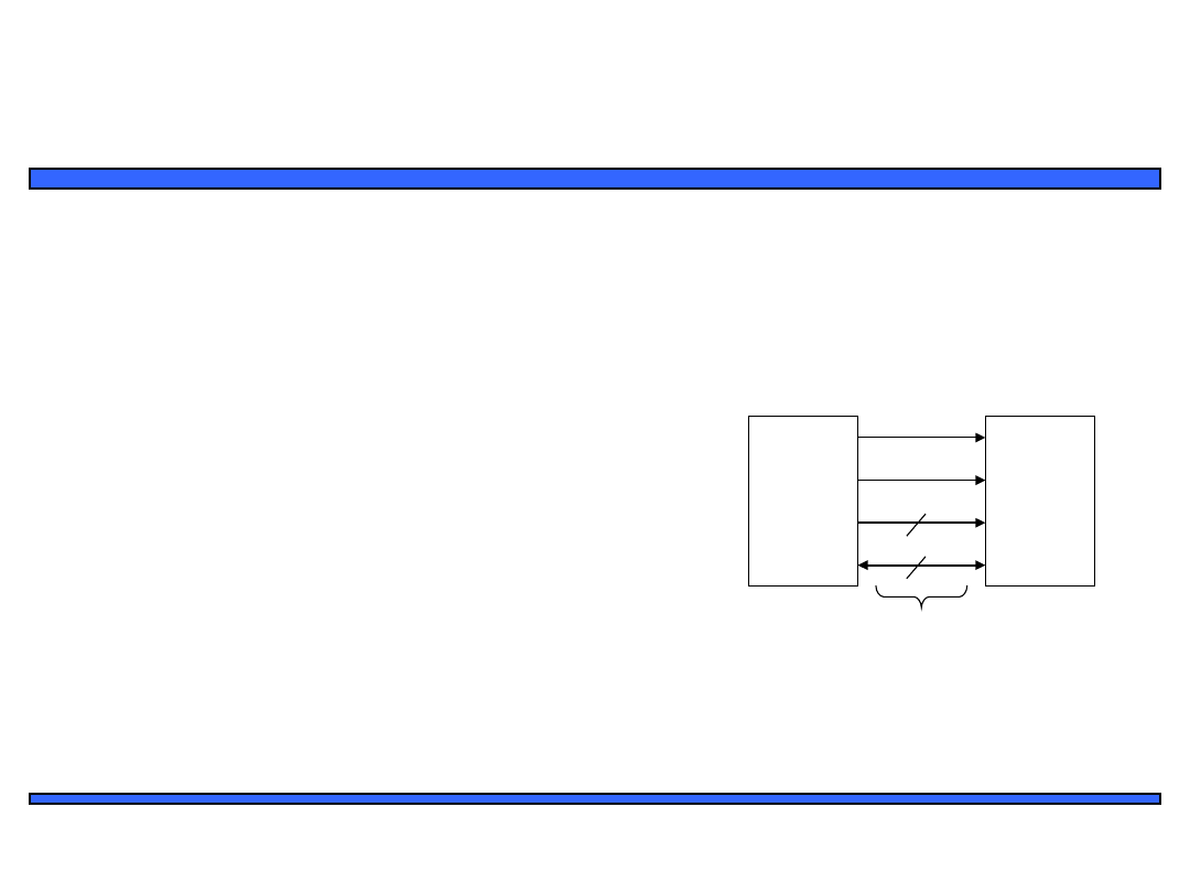
A simple bus
bus structure
Processor
Memory
rd'/wr
enable
addr[0-11]
data[0-7]
bus
• Wires:
– Uni-directional or bi-directional
– One line may represent multiple
wires
• Bus
– Set of wires with a single function
• Address bus, data bus
– Or, entire collection of wires
• Address, data and control
• Associated protocol: rules for
communication
5
Embedded Systems Design: A Unified
Hardware/Software Introduction,
(c) 2000
Vahid/Givargis
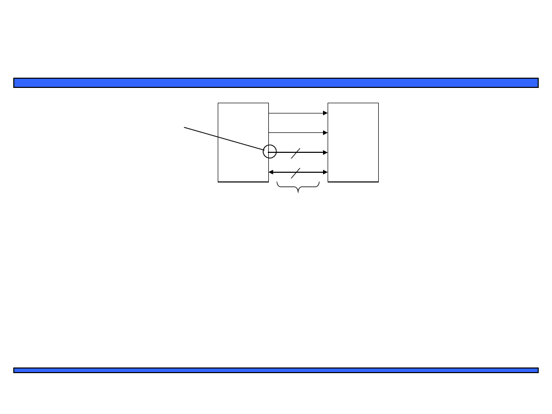
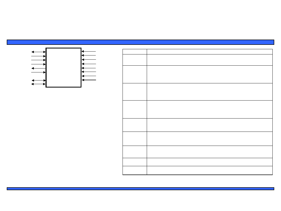
Ports
• Conducting device on periphery
• Connects bus to processor or memory
• Often referred to as a pin
–
Actual pins on periphery of IC package that plug into socket on printed-
circuit board
–
Sometimes metallic balls instead of pins
–
Today, metal “pads” connecting processors and memories within single IC
• Single wire or set of wires with single function
–
E.g., 12-wire address port
bus
Processor
Memory
rd'/wr
enable
addr[0-11]
data[0-7]
port
6
Embedded Systems Design: A Unified
Hardware/Software Introduction,
(c) 2000
Vahid/Givargis
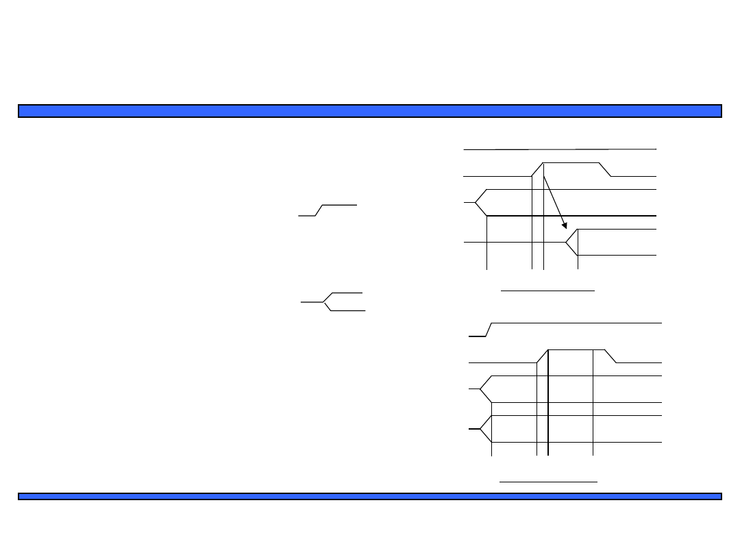
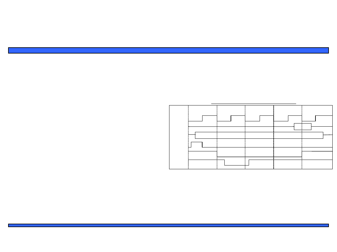
Timing Diagrams
write protocol
rd'/wr
enable
addr
data
t
setup
t
write
• Most common method for describing
a communication protocol
• Time proceeds to the right on x-axis
• Control signal: low or high
– May be active low (e.g., go’, /go, or
go_L)
– Use terms assert (active) and deassert
– Asserting go’ means go=0
• Data signal: not valid or valid
• Protocol may have subprotocols
– Called bus cycle, e.g., read and write
– Each may be several clock cycles
• Read example
– rd’/wr set low,address placed on addr
for at least t
setup
time before enable
asserted, enable triggers memory to
place data on data wires by time t
read
read protocol
rd'/wr
enable
addr
data
t
setup
t
read
7
Embedded Systems Design: A Unified
Hardware/Software Introduction,
(c) 2000
Vahid/Givargis
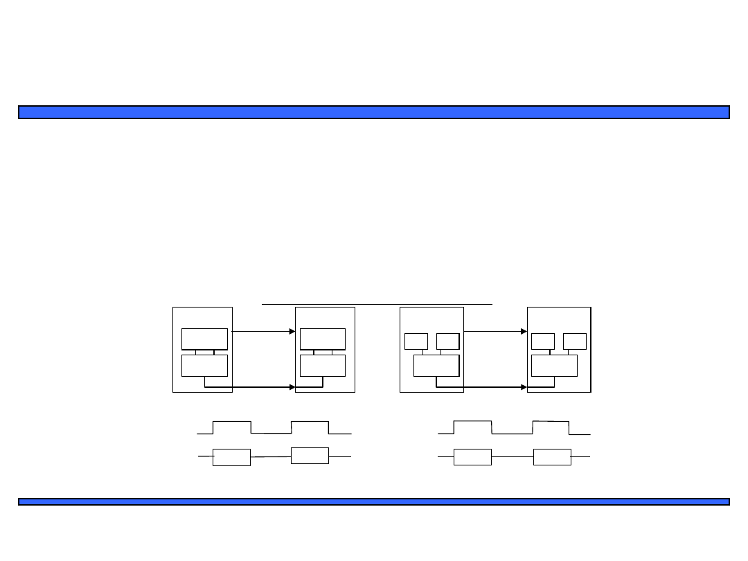
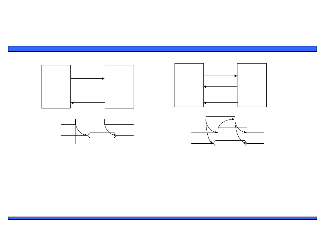
Basic protocol concepts
• Actor: master initiates, servant (slave) respond
• Direction: sender, receiver
• Addresses: special kind of data
– Specifies a location in memory, a peripheral, or a register within a peripheral
• Time multiplexing
– Share a single set of wires for multiple pieces of data
– Saves wires at expense of time
data serializing
address/data muxing
Master
Servant
req
data(8
)
data(15:0)
data(15:0)
mux
demux
Master
Servant
req
addr/data
req
addr/da
ta
addr data
mux
demux
addr data
req
dat
a
15:8
7:0
addr
data
Time-multiplexed data transfer
8
Embedded Systems Design: A Unified
Hardware/Software Introduction,
(c) 2000
Vahid/Givargis
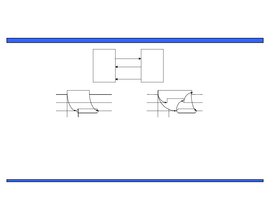
Basic protocol concepts: control
methods
Strobe protocol
Handshake protocol
Master
Servant
req
ack
req
data
Master
Servant
data
req
data
t
access
req
data
ack
1. Master asserts req to receive
data
2. Servant puts data on bus within
time t
access
1
2
3
4
3. Master receives data and deasserts
req
4. Servant ready for next request
1
2
3
4
1. Master asserts req to receive
data
2. Servant puts data on bus and
asserts ack
3. Master receives data and deasserts
req
4. Servant ready for next request
9
Embedded Systems Design: A Unified
Hardware/Software Introduction,
(c) 2000
Vahid/Givargis
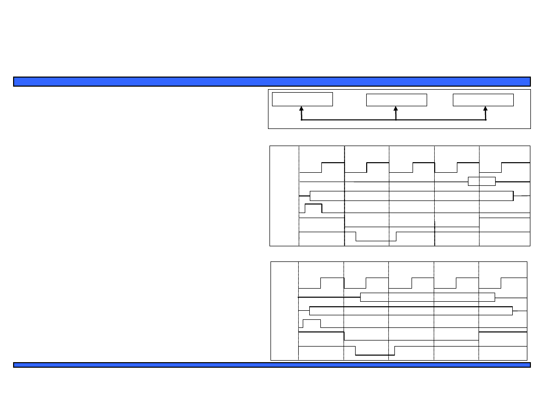
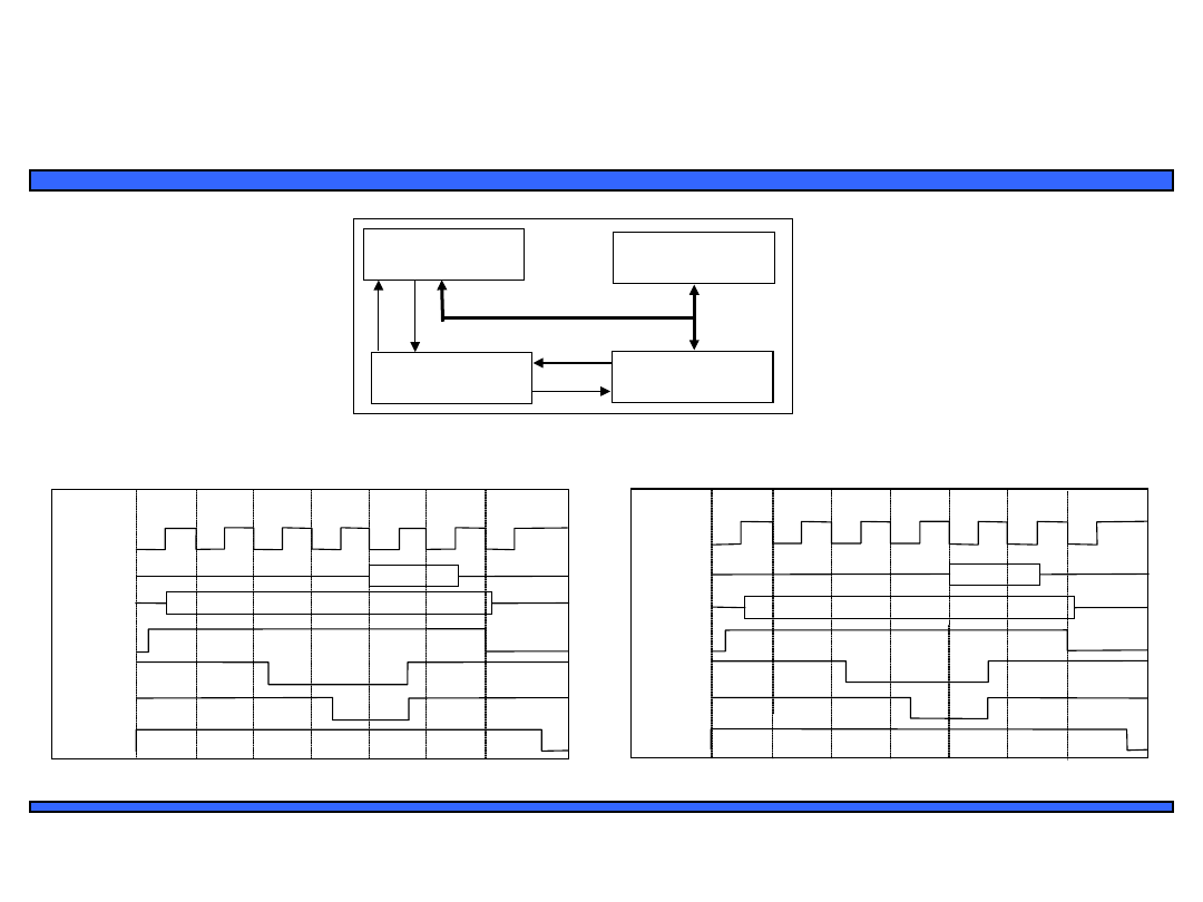
A strobe/handshake compromise
Fast-response case
req
data
wait
1
3
4
1. Master asserts req to receive
data
2. Servant puts data on bus within
time t
access
3. Master receives data and
deasserts req
4. Servant ready for next request
2
Slow-response case
Master
Servant
req
wait
data
req
data
wait
1
3
4
1. Master asserts req to receive
data
2. Servant can't put data within t
access
,
asserts wait ack
3. Servant puts data on bus and
deasserts wait
4. Master receives data and
deasserts req
2
t
access
t
access
5. Servant ready for next request
5
(wait line is unused)
10
Embedded Systems Design: A Unified
Hardware/Software Introduction,
(c) 2000
Vahid/Givargis
ISA bus protocol – memory access
Microproces
sor
Memory
I/O Device
ISA bus
ADDRESS
CYCLE
CLOCK
D[7-0]
A[19-0]
ALE
/
MEMR
CHRD
Y
C1 C2 WAIT
C3 C4
DATA
• ISA: Industry
Standard Architecture
– Common in 80x86’s
• Features
– 20-bit address
– Compromise
strobe/handshake
control
• 4 cycles default
• Unless CHRDY
deasserted – resulting
in additional wait
cycles (up to 6)
memory-read bus cycle
CYCLE
CLOCK
D[7-0]
A[19-0]
ALE
/
MEMW
CHRDY
C1 C2 WAIT
C3 C4
DATA
ADDRESS
memory-write bus cycle

11
Embedded Systems Design: A Unified
Hardware/Software Introduction,
(c) 2000
Vahid/Givargis
Microprocessor interfacing: I/O
addressing
• A microprocessor communicates with other
devices using some of its pins
– Port-based I/O (parallel I/O)
• Processor has one or more N-bit ports
• Processor’s software reads and writes a port just like a
register
• E.g., P0 = 0xFF; v = P1.2; -- P0 and P1 are 8-bit ports
– Bus-based I/O
• Processor has address, data and control ports that form a
single bus
• Communication protocol is built into the processor
• A single instruction carries out the read or write protocol on
the bus
12
Embedded Systems Design: A Unified
Hardware/Software Introduction,
(c) 2000
Vahid/Givargis
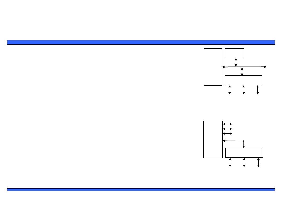
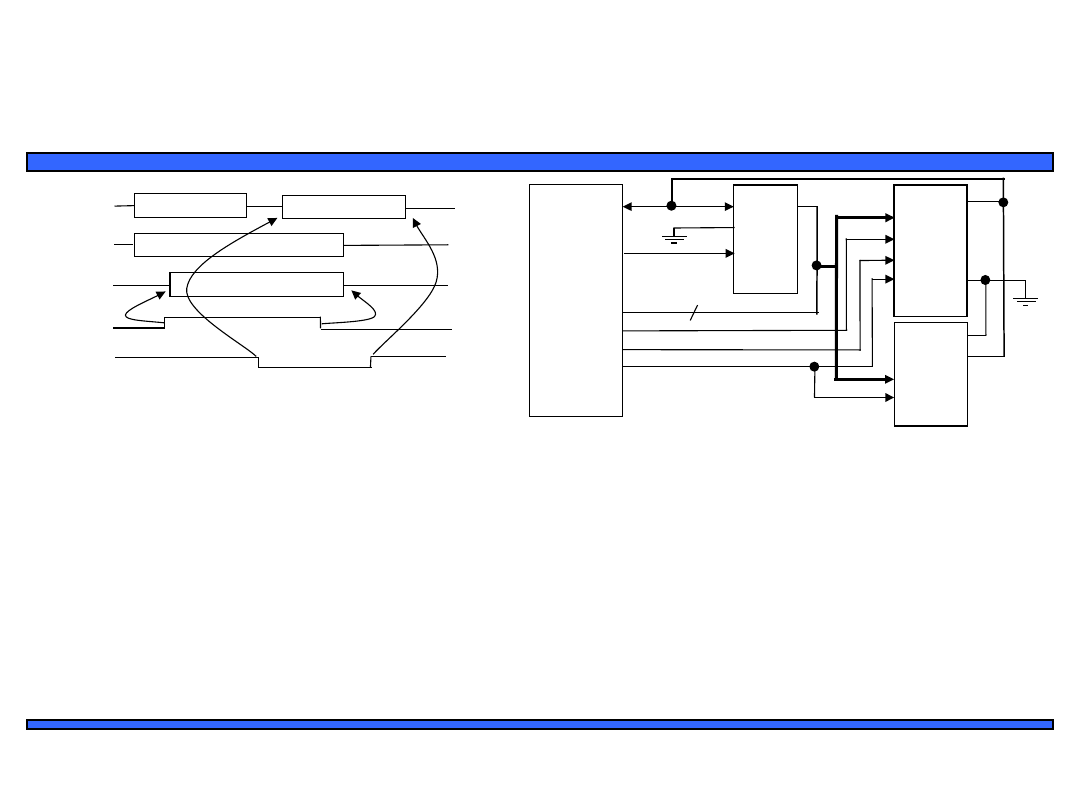
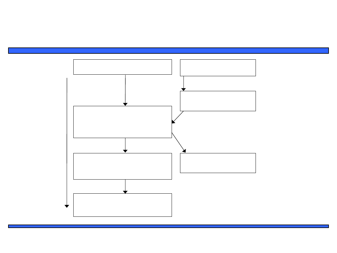
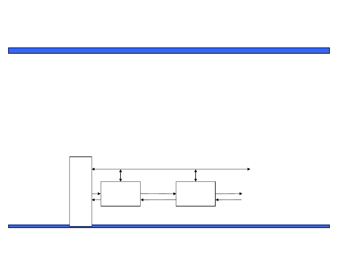
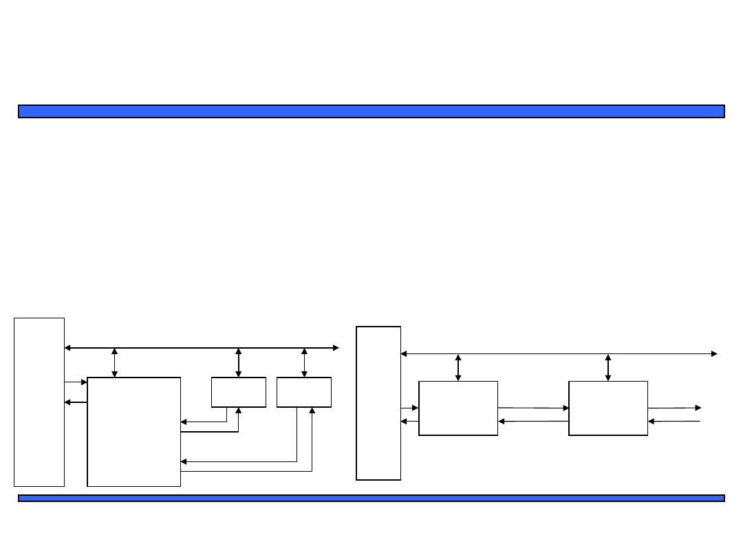
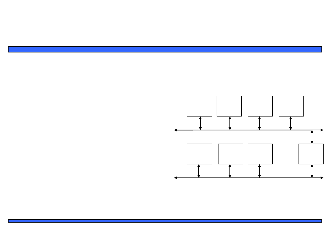
Compromises/extensions
• Parallel I/O peripheral
– When processor only supports bus-based
I/O but parallel I/O needed
– Each port on peripheral connected to a
register within peripheral that is
read/written by the processor
• Extended parallel I/O
– When processor supports port-based I/O
but more ports needed
– One or more processor ports interface
with parallel I/O peripheral extending
total number of ports available for I/O
– e.g., extending 4 ports to 6 ports in figure
Processor
Memory
Parallel I/O
peripheral
Port A
System bus
Port
C
Port B
Adding parallel I/O to a
bus-based I/O processor
Processor
Parallel I/O
peripheral
Port APort BPort C
Port 0
Port 1
Port 2
Port 3
Extended parallel I/O

13
Embedded Systems Design: A Unified
Hardware/Software Introduction,
(c) 2000
Vahid/Givargis
Types of bus-based I/O:
memory-mapped I/O and standard
I/O
• Processor talks to both memory and peripherals
using same bus – two ways to talk to peripherals
– Memory-mapped I/O
• Peripheral registers occupy addresses in same address space
as memory
• e.g., Bus has 16-bit address
– lower 32K addresses may correspond to memory
– upper 32k addresses may correspond to peripherals
– Standard I/O (I/O-mapped I/O)
• Additional pin (M/IO) on bus indicates whether a memory or
peripheral access
• e.g., Bus has 16-bit address
– all 64K addresses correspond to memory when M/IO set to 0
– all 64K addresses correspond to peripherals when M/IO set to 1

14
Embedded Systems Design: A Unified
Hardware/Software Introduction,
(c) 2000
Vahid/Givargis
Memory-mapped I/O vs. Standard
I/O
• Memory-mapped I/O
– Requires no special instructions
• Assembly instructions involving memory like MOV and
ADD work with peripherals as well
• Standard I/O requires special instructions (e.g., IN, OUT)
to move data between peripheral registers and memory
• Standard I/O
– No loss of memory addresses to peripherals
– Simpler address decoding logic in peripherals
possible
• When number of peripherals much smaller than address
space then high-order address bits can be ignored
– smaller and/or faster comparators
15
Embedded Systems Design: A Unified
Hardware/Software Introduction,
(c) 2000
Vahid/Givargis
ISA bus
• ISA supports standard
I/O
– /IOR distinct from
/MEMR for peripheral
read
• /IOW used for writes
– 16-bit address space for
I/O vs. 20-bit address
space for memory
– Otherwise very similar to
memory protocol
CYCLE
CLOCK
D[7-0]
A[15-0]
ALE
/IOR
CHRDY
C1 C2 WAIT C3
C4
DATA
ADDRESS
ISA I/O bus read protocol
16
Embedded Systems Design: A Unified
Hardware/Software Introduction,
(c) 2000
Vahid/Givargis
A basic memory protocol
• Interfacing an 8051 to external memory
– Ports P0 and P2 support port-based I/O when 8051 internal
memory being used
– Those ports serve as data/address buses when external
memory is being used
– 16-bit address and 8-bit data are time multiplexed; low 8-bits
of address must therefore be latched with aid of ALE signal
P0
P2
Q
ALE
/RD
Adr. 7..0
Adr. 15…8
Adr. 7…0
Data
8051
74373
P0
HM6264
D
Q
8
P2
ALE
G
A<0...1
5>
D<0...
7>
/OE
/WE
/CS
/
WR/
RD
/
CS
1
/
PSEN
CS
2
27C256
/CS
A<0...14
>
D<0...7
>
/OE
17
Embedded Systems Design: A Unified
Hardware/Software Introduction,
(c) 2000
Vahid/Givargis
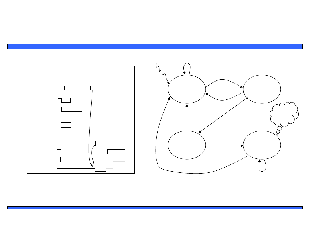
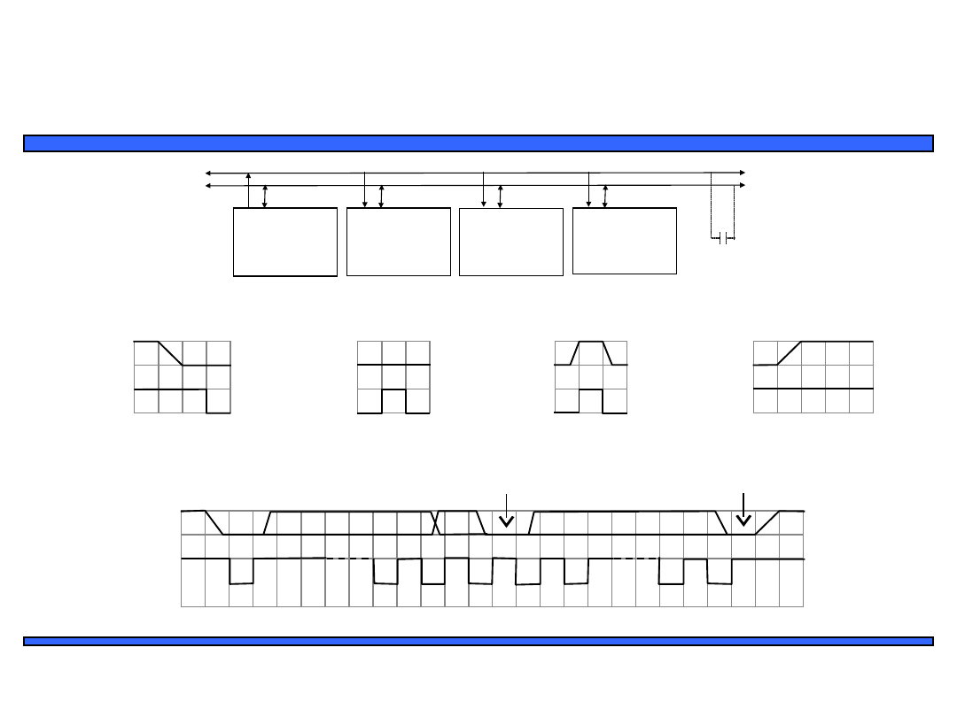
A more complex memory protocol
• Generates control signals to drive the TC55V2325FF memory chip in burst mode
– Addr0 is the starting address input to device
– GO is enable/disable input to device
Specification for a
single read
operation
CLK
/ADSP
/ADSC
/ADV
addr <15…0>
/WE
/OE
/CS1 and /CS2
CS3
data<31…0>
ADSP=1,
ADSC=1
ADV=1,
OE=1, Addr
= ‘Z’
ADSP=1,
ADSC=0
ADV=1,
OE=1, Addr
= ‘Z’
ADSP=1,
ADSC=1
ADV=0,
OE=0, Addr
= ‘Z’
GO=
1
GO=
0
Data is
ready
here!
GO=
1
GO=
1
GO=
0
GO=
0
S
0
S
1
S2
S
3
ADSP=0,
ADSC=0
ADV=0,
OE=1, Addr
= Addr0
GO=
0
GO=1
FSM description

18
Embedded Systems Design: A Unified
Hardware/Software Introduction,
(c) 2000
Vahid/Givargis
Microprocessor interfacing:
interrupts
• Suppose a peripheral intermittently receives
data, which must be serviced by the processor
– The processor can poll the peripheral regularly to
see if data has arrived – wasteful
– The peripheral can interrupt the processor when it
has data
• Requires an extra pin or pins: Int
– If Int is 1, processor suspends current program,
jumps to an Interrupt Service Routine, or ISR
– Known as interrupt-driven I/O
– Essentially, “polling” of the interrupt pin is built-
into the hardware, so no extra time!

19
Embedded Systems Design: A Unified
Hardware/Software Introduction,
(c) 2000
Vahid/Givargis
Microprocessor interfacing:
interrupts
• What is the address (interrupt address
vector) of the ISR?
– Fixed interrupt
• Address built into microprocessor, cannot be changed
• Either ISR stored at address or a jump to actual ISR
stored if not enough bytes available
– Vectored interrupt
• Peripheral must provide the address
• Common when microprocessor has multiple
peripherals connected by a system bus
– Compromise: interrupt address table
20
Embedded Systems Design: A Unified
Hardware/Software Introduction,
(c) 2000
Vahid/Givargis
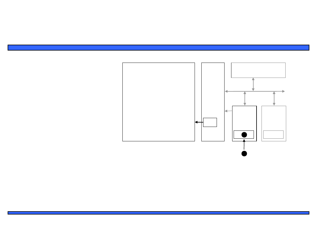
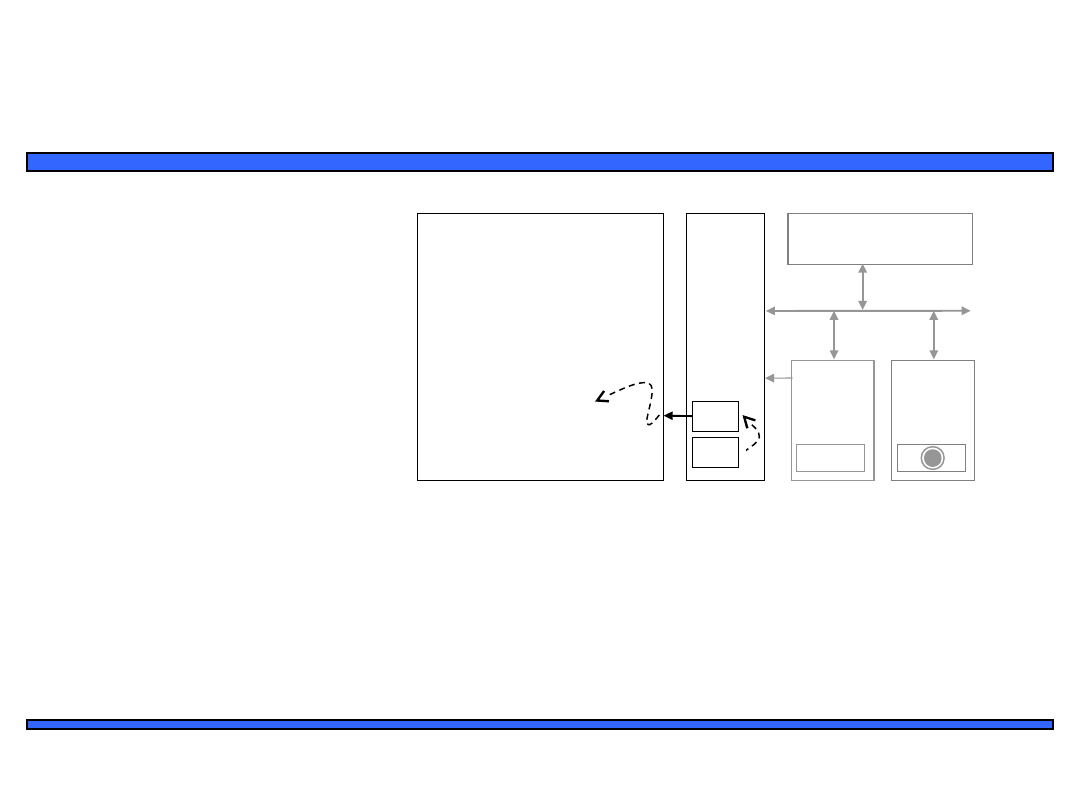
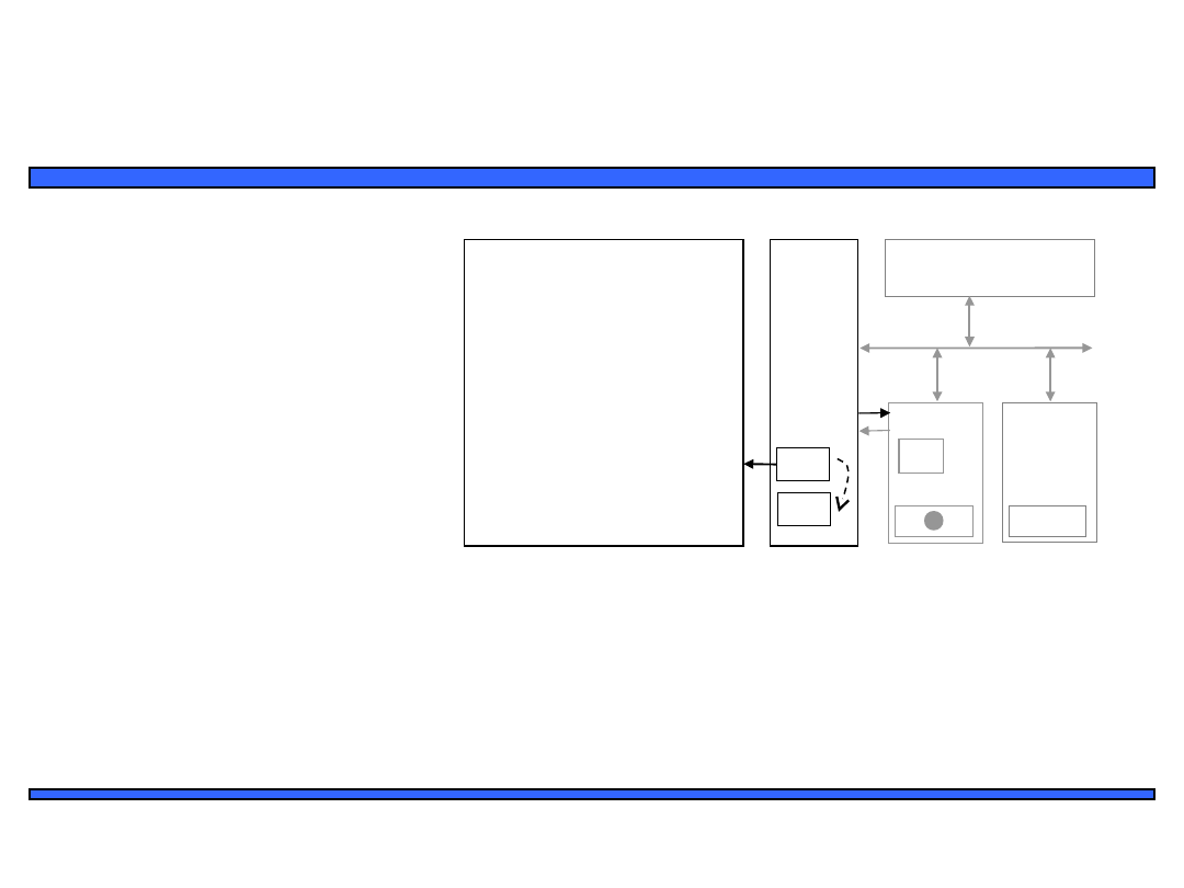
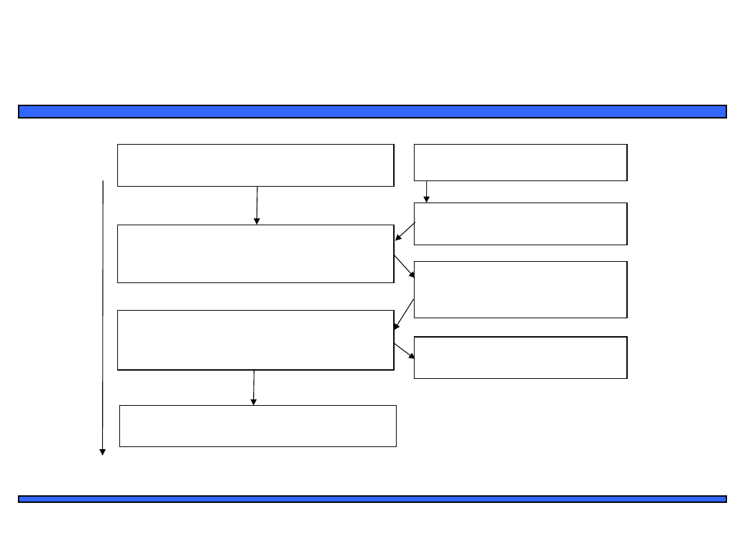
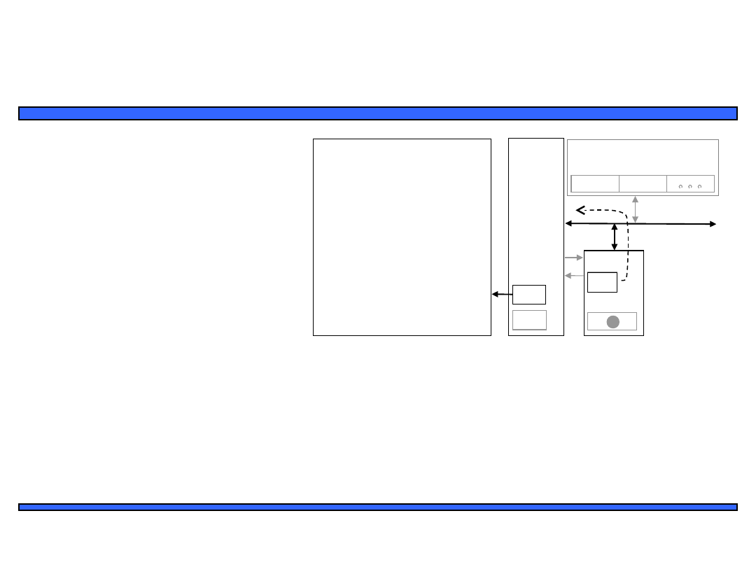
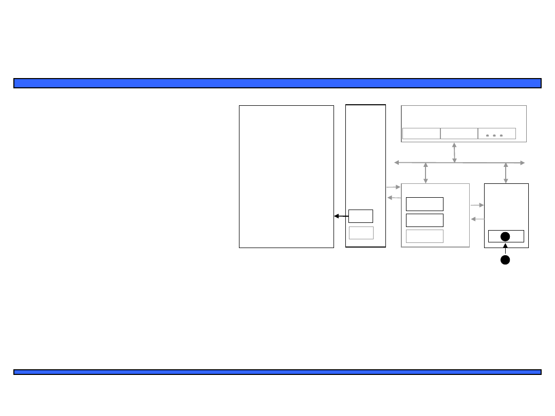
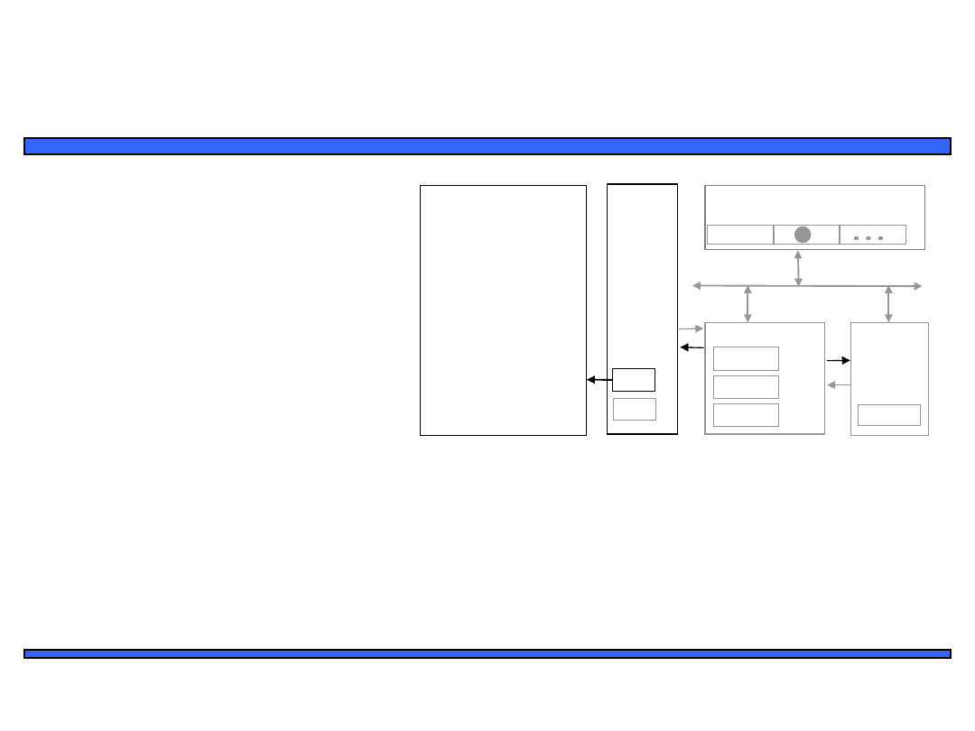
Interrupt-driven I/O using fixed ISR
location
1(a): μP is executing its main
program.
1(b): P1 receives input
data in a register with
address 0x8000.
2: P1 asserts Int to
request servicing by the
microprocessor.
3: After completing instruction
at 100, μP sees Int asserted,
saves the PC’s value of 100, and
sets PC to the ISR fixed location
of 16.
4(a): The ISR reads data from
0x8000, modifies the data, and
writes the resulting data to
0x8001.
5: The ISR returns, thus
restoring PC to 100+1=101,
where μP resumes executing.
4(b): After being read,
P1 de-asserts Int.
Ti
me
21
Embedded Systems Design: A Unified
Hardware/Software Introduction,
(c) 2000
Vahid/Givargis
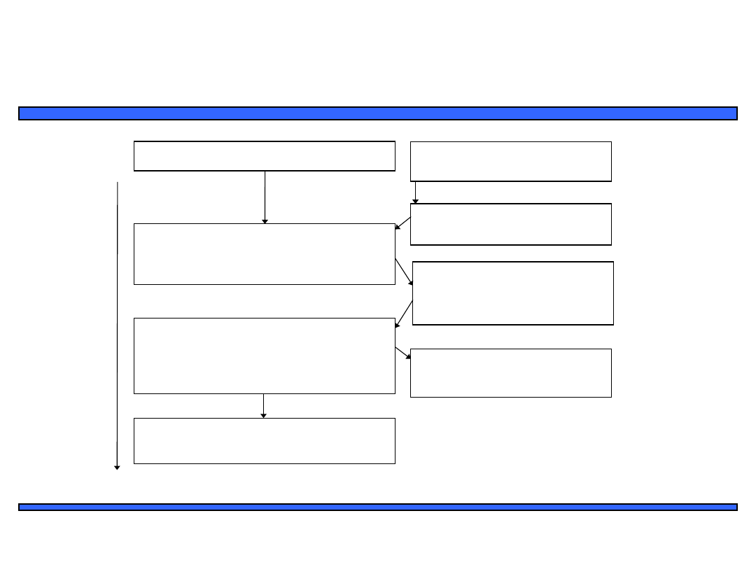
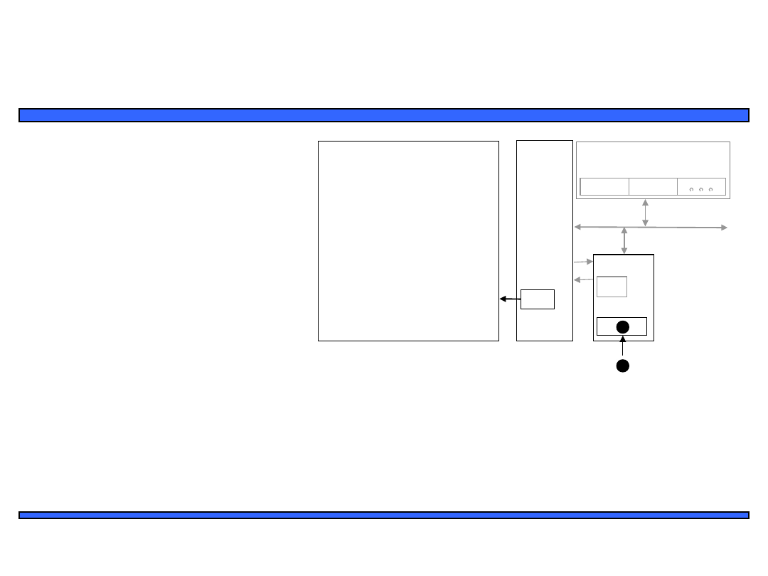
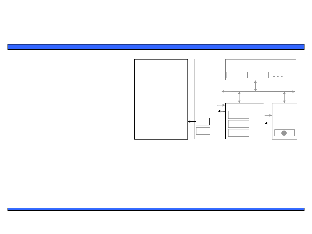
Interrupt-driven I/O using fixed ISR
location
1(a): P is executing its main
program
1(b): P1 receives input data in
a register with address
0x8000.
μP
P1
P2
System
bus
Int
Data memory
0x800
0
0x800
1
16: MOV R0,
0x8000
17: # modifies
R0
18: MOV 0x8001, R0
19: RETI # ISR
return
ISR
100:
101
:
instructio
n
instructio
n
...
Main
program
...
Program
memory
PC
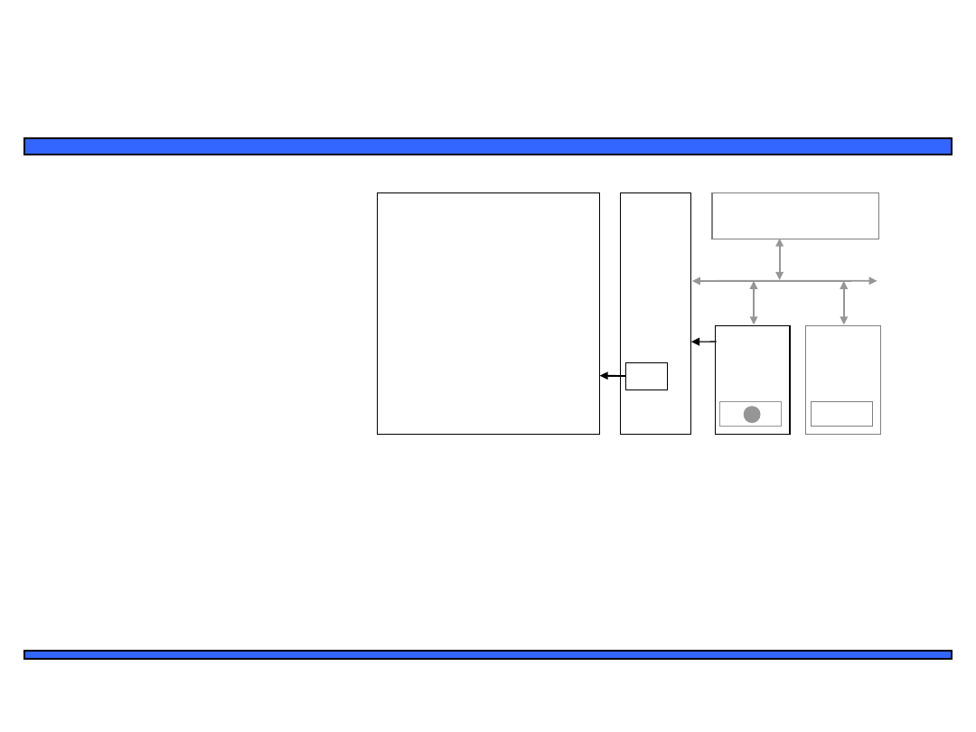
22
Embedded Systems Design: A Unified
Hardware/Software Introduction,
(c) 2000
Vahid/Givargis
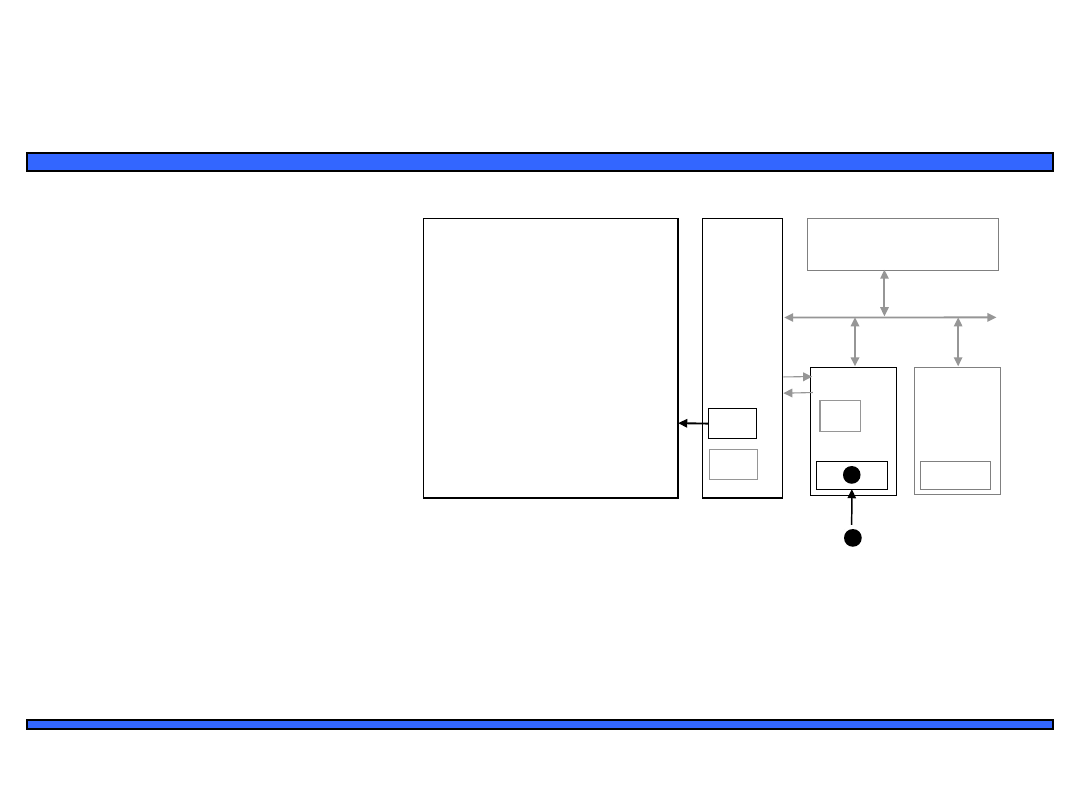
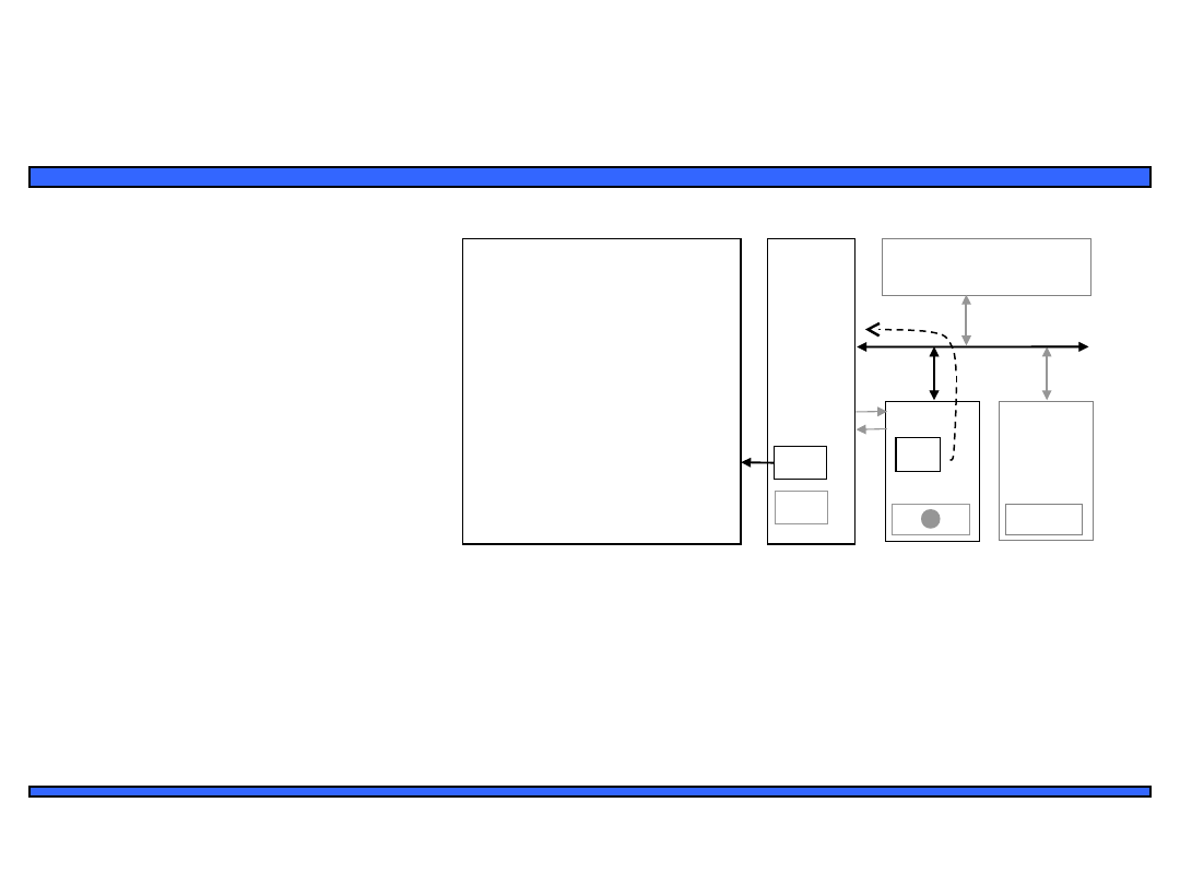
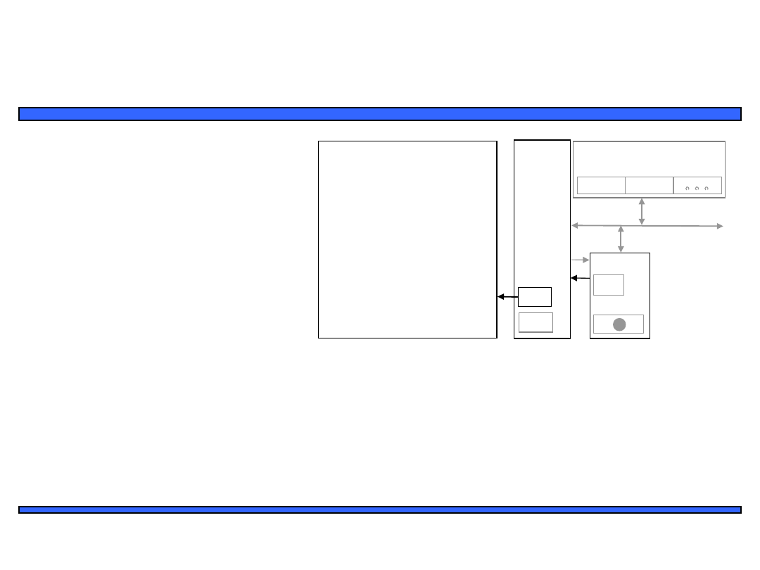
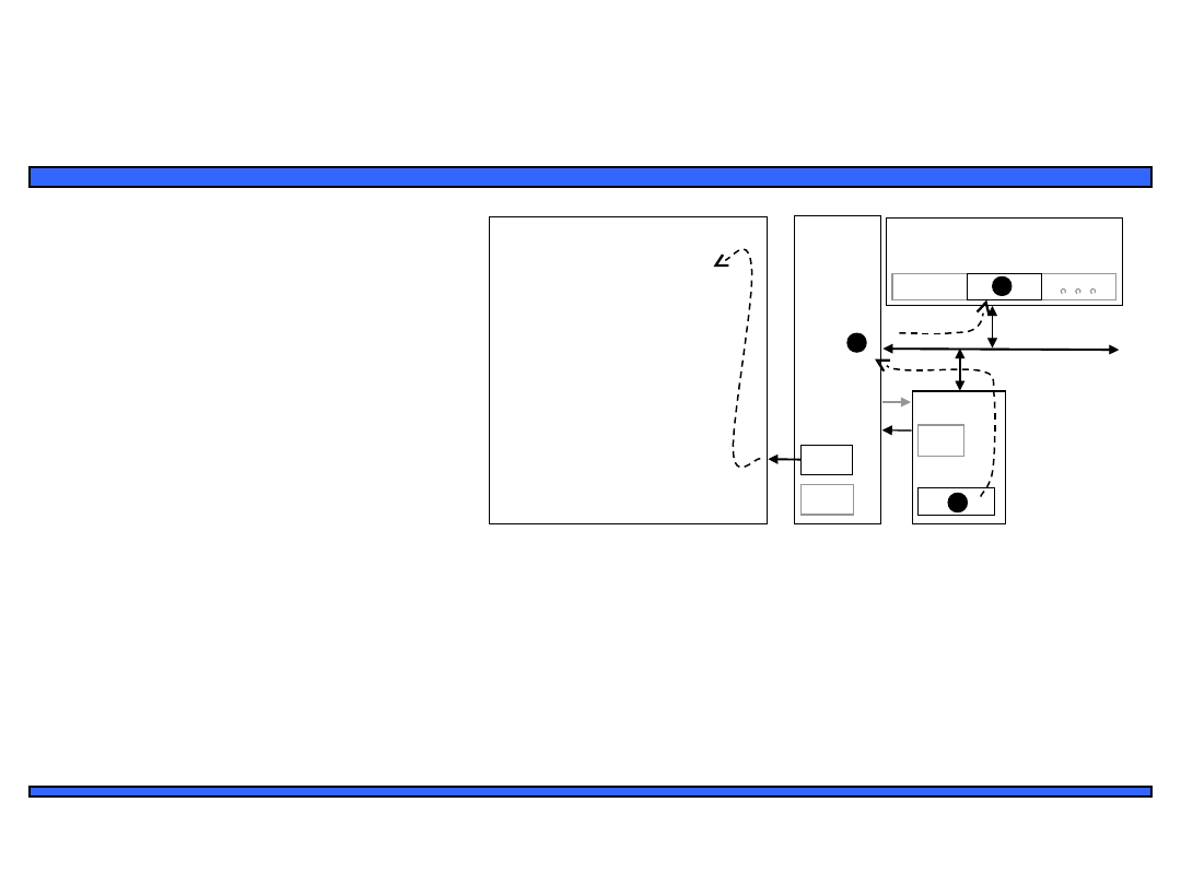
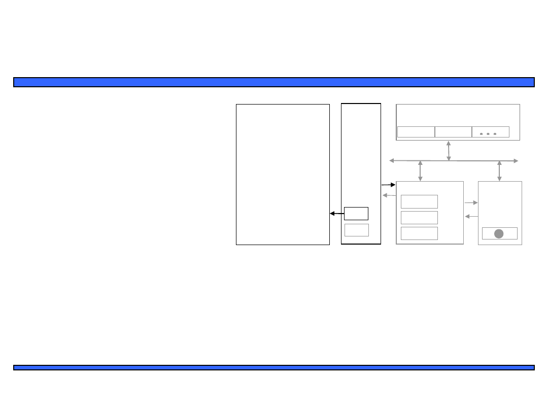
Interrupt-driven I/O using fixed ISR
location
2: P1 asserts Int to request
servicing by the
microprocessor
μP
P1
P2
System
bus
Data memory
0x800
0
0x800
1
16: MOV R0,
0x8000
17: # modifies
R0
18: MOV 0x8001, R0
19: RETI # ISR
return
ISR
100:
101
:
instructio
n
instructio
n
...
Main
program
...
Program
memory
PC
Int
Int
1
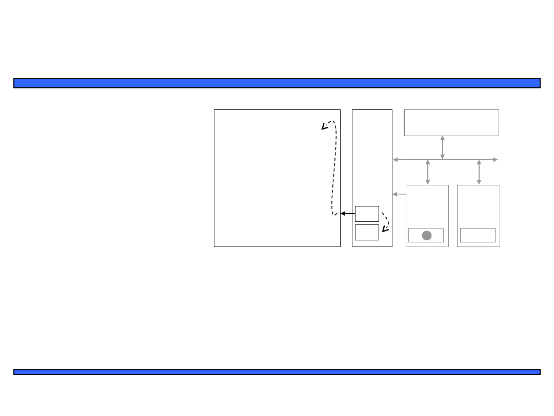
23
Embedded Systems Design: A Unified
Hardware/Software Introduction,
(c) 2000
Vahid/Givargis
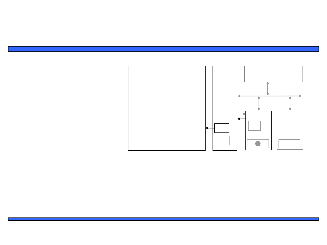
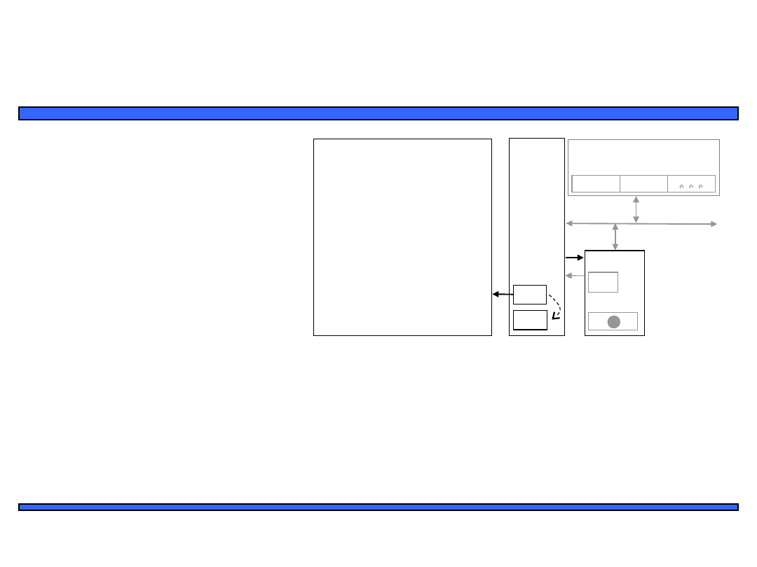
Interrupt-driven I/O using fixed ISR
location
3: After completing instruction
at 100, P sees Int asserted,
saves the PC’s value of 100,
and sets PC to the ISR fixed
location of 16.
μP
P1
P2
System
bus
Data memory
0x800
0
0x800
1
16: MOV R0,
0x8000
17: # modifies
R0
18: MOV 0x8001, R0
19: RETI # ISR
return
ISR
100:
101
:
instructio
n
instructio
n
...
Main
program
...
Program
memory
PC
Int
100
100
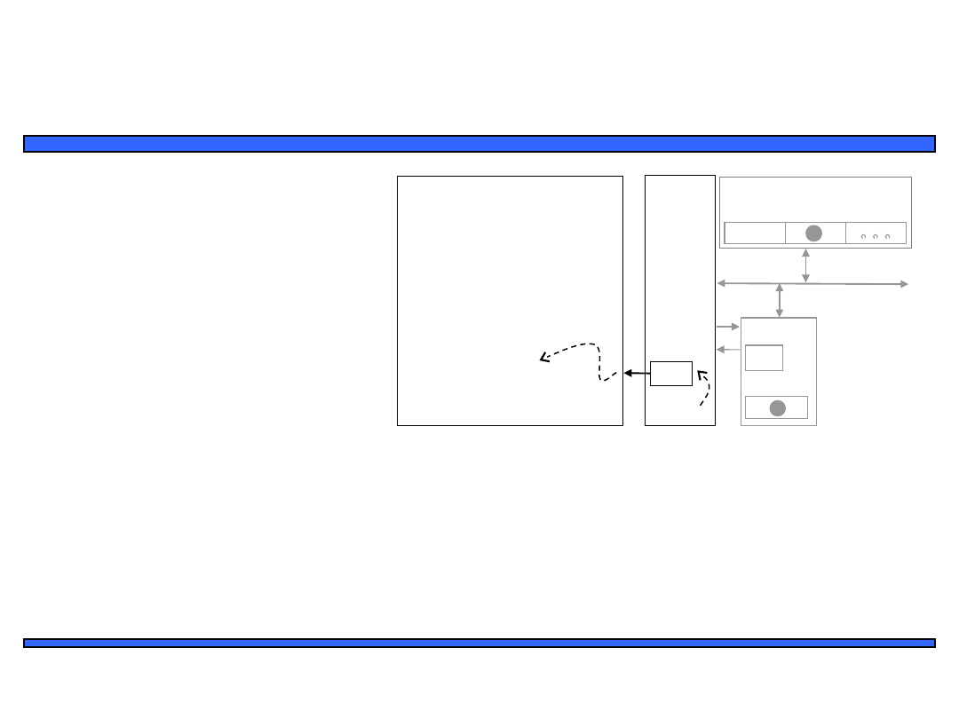
24
Embedded Systems Design: A Unified
Hardware/Software Introduction,
(c) 2000
Vahid/Givargis
μP
P1
P2
System
bus
Data memory
0x800
0
0x800
1
16: MOV R0,
0x8000
17: # modifies
R0
18: MOV 0x8001, R0
19: RETI # ISR
return
ISR
100:
101
:
instructio
n
instructio
n
...
Main
program
...
Program
memory
PC
Int
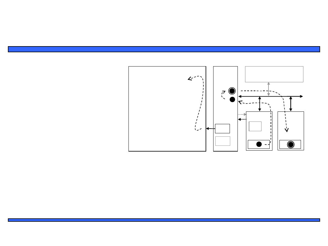
Interrupt-driven I/O using fixed ISR
location
4(a): The ISR reads data from
0x8000, modifies the data, and
writes the resulting data to
0x8001.
4(b): After being read, P1
deasserts Int.
100
Int
0
P1
System
bus
P1
0x800
0
P2
0x800
1
25
Embedded Systems Design: A Unified
Hardware/Software Introduction,
(c) 2000
Vahid/Givargis
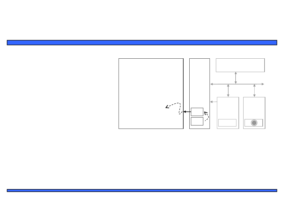
Interrupt-driven I/O using fixed ISR
location
5: The ISR returns, thus
restoring PC to 100+1=101,
where P resumes executing.
μP
P1
P2
System
bus
Data memory
0x800
0
0x800
1
16: MOV R0,
0x8000
17: # modifies
R0
18: MOV 0x8001, R0
19: RETI # ISR
return
ISR
100:
101
:
instructio
n
instructio
n
...
Main
program
...
Program
memory
PC
Int
100
100
+1
16: MOV R0,
0x8000
17: # modifies
R0
18: MOV 0x8001, R0
19: RETI # ISR
return
ISR
100:
101
:
instructio
n
instructio
n
...
Main
program
...
100
26
Embedded Systems Design: A Unified
Hardware/Software Introduction,
(c) 2000
Vahid/Givargis
Interrupt-driven I/O using vectored
interrupt
1(a): μP is executing its main program.
1(b): P1 receives input data
in a register with address
0x8000.
2: P1 asserts Int to request
servicing by the
microprocessor.
3: After completing instruction at 100,
μP sees Int asserted, saves the PC’s
value of 100, and asserts Inta.
5(a): μP jumps to the address on
the bus (16). The ISR there reads
data from 0x8000, modifies the data,
and writes the resulting data to
0x8001.
6: The ISR returns, thus restoring PC
to 100+1=101, where μP resumes
executing.
5(b): After being read, P1
deasserts Int.
Ti
me
4: P1 detects Inta and puts
interrupt address vector
16 on the data bus.
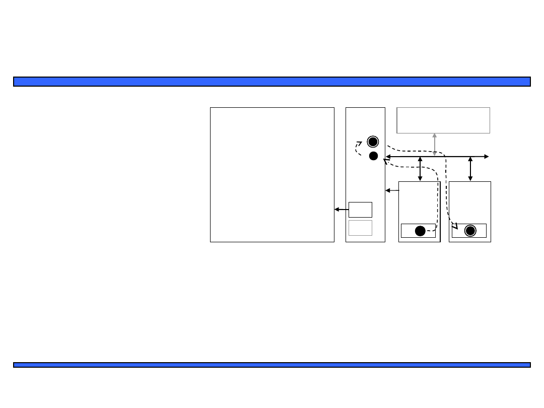
27
Embedded Systems Design: A Unified
Hardware/Software Introduction,
(c) 2000
Vahid/Givargis
Interrupt-driven I/O using vectored
interrupt
μP
P1
P2
System
bus
Data memory
0x800
0
0x800
1
16: MOV R0,
0x8000
17: # modifies
R0
18: MOV 0x8001, R0
19: RETI # ISR
return
ISR
100:
101
:
instructio
n
instructio
n
...
Main
program
...
Program
memory
PC
100
Int
Inta
16
1(a): P is executing its main
program
1(b): P1 receives input data in a
register with address 0x8000.
28
Embedded Systems Design: A Unified
Hardware/Software Introduction,
(c) 2000
Vahid/Givargis
Interrupt-driven I/O using vectored
interrupt
μP
P1
P2
System
bus
Data memory
0x800
0
0x800
1
16: MOV R0,
0x8000
17: # modifies
R0
18: MOV 0x8001, R0
19: RETI # ISR
return
ISR
100:
101
:
instructio
n
instructio
n
...
Main
program
...
Program
memory
PC
100
Inta
16
2: P1 asserts Int to request
servicing by the microprocessor
Int
1
Int
29
Embedded Systems Design: A Unified
Hardware/Software Introduction,
(c) 2000
Vahid/Givargis
Interrupt-driven I/O using vectored
interrupt
3: After completing instruction at
100, μP sees Int asserted, saves
the PC’s value of 100, and
asserts Inta
μP
P1
P2
System
bus
Data memory
0x800
0
0x800
1
16: MOV R0,
0x8000
17: # modifies
R0
18: MOV 0x8001, R0
19: RETI # ISR
return
ISR
100:
101
:
instructio
n
instructio
n
...
Main
program
...
Program
memory
PC
Int
Inta
16
100
100
1
Inta
30
Embedded Systems Design: A Unified
Hardware/Software Introduction,
(c) 2000
Vahid/Givargis
μP
P1
P2
System
bus
Data memory
0x800
0
0x800
1
16: MOV R0,
0x8000
17: # modifies
R0
18: MOV 0x8001, R0
19: RETI # ISR
return
ISR
100:
101
:
instructio
n
instructio
n
...
Main
program
...
Program
memory
PC
Int
Inta
16
Interrupt-driven I/O using vectored
interrupt
100
4: P1 detects Inta and puts
interrupt address vector 16 on
the data bus
16
16
System
bus
31
Embedded Systems Design: A Unified
Hardware/Software Introduction,
(c) 2000
Vahid/Givargis
Interrupt-driven I/O using vectored
interrupt
5(a): PC jumps to the address on
the bus (16). The ISR there reads
data from 0x8000, modifies the
data, and writes the resulting
data to 0x8001.
5(b): After being read, P1
deasserts Int.
μP
P1
P2
System
bus
Data memory
0x800
0
0x800
1
16: MOV R0,
0x8000
17: # modifies
R0
18: MOV 0x8001, R0
19: RETI # ISR
return
ISR
100:
101
:
instructio
n
instructio
n
...
Main
program
...
Program
memory
PC
Int
Inta
16
100
16: MOV R0,
0x8000
17: # modifies
R0
18: MOV 0x8001, R0
19: RETI # ISR
return
ISR
100:
101
:
instructio
n
instructio
n
...
Main
program
...
P1
P2
0x800
0
0x800
1
System
bus
0
Int
32
Embedded Systems Design: A Unified
Hardware/Software Introduction,
(c) 2000
Vahid/Givargis
Interrupt-driven I/O using vectored
interrupt
6: The ISR returns, thus restoring
the PC to 100+1=101, where the
μP resumes
μP
P1
P2
System
bus
Data memory
0x800
0
0x800
1
16: MOV R0,
0x8000
17: # modifies
R0
18: MOV 0x8001, R0
19: RETI # ISR
return
ISR
100:
101
:
instructio
n
instructio
n
...
Main
program
...
Program
memory
PC
Int
100
100
+1
16: MOV R0,
0x8000
17: # modifies
R0
18: MOV 0x8001, R0
19: RETI # ISR
return
ISR
100:
101
:
instructio
n
instructio
n
...
Main
program
...
100

33
Embedded Systems Design: A Unified
Hardware/Software Introduction,
(c) 2000
Vahid/Givargis
Interrupt address table
• Compromise between fixed and vectored
interrupts
– One interrupt pin
– Table in memory holding ISR addresses (maybe
256 words)
– Peripheral doesn’t provide ISR address, but
rather index into table
• Fewer bits are sent by the peripheral
• Can move ISR location without changing peripheral

34
Embedded Systems Design: A Unified
Hardware/Software Introduction,
(c) 2000
Vahid/Givargis
Additional interrupt issues
•
Maskable vs. non-maskable interrupts
– Maskable: programmer can set bit that causes processor to
ignore interrupt
• Important when in the middle of time-critical code
– Non-maskable: a separate interrupt pin that can’t be masked
• Typically reserved for drastic situations, like power failure requiring
immediate backup of data to non-volatile memory
•
Jump to ISR
– Some microprocessors treat jump same as call of any subroutine
• Complete state saved (PC, registers) – may take hundreds of cycles
– Others only save partial state, like PC only
• Thus, ISR must not modify registers, or else must save them first
• Assembly-language programmer must be aware of which registers
stored

35
Embedded Systems Design: A Unified
Hardware/Software Introduction,
(c) 2000
Vahid/Givargis
Direct memory access
• Buffering
– Temporarily storing data in memory before processing
– Data accumulated in peripherals commonly buffered
• Microprocessor could handle this with ISR
– Storing and restoring microprocessor state inefficient
– Regular program must wait
• DMA controller more efficient
– Separate single-purpose processor
– Microprocessor relinquishes control of system bus to DMA
controller
– Microprocessor can meanwhile execute its regular program
• No inefficient storing and restoring state due to ISR call
• Regular program need not wait unless it requires the system bus
– Harvard archictecture – processor can fetch and execute instructions as
long as they don’t access data memory – if they do, processor stalls
36
Embedded Systems Design: A Unified
Hardware/Software Introduction,
(c) 2000
Vahid/Givargis
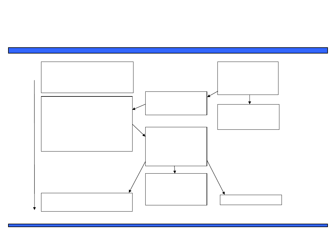
Peripheral to memory transfer
without DMA, using vectored
interrupt
1(a): μP is executing its main program.
1(b): P1 receives input data in a
register with address 0x8000.
2: P1 asserts Int to request
servicing by the microprocessor.
3: After completing instruction at 100, μP
sees Int asserted, saves the PC’s value of
100, and asserts Inta.
5(a): μP jumps to the address on the bus
(16). The ISR there reads data from
0x8000 and then writes it to 0x0001,
which is in memory.
6: The ISR returns, thus restoring PC to
100+1=101, where μP resumes executing.
5(b): After being read, P1
deasserts Int.
Ti
m
e
4: P1 detects Inta and puts
interrupt address vector 16 on
the data bus.
37
Embedded Systems Design: A Unified
Hardware/Software Introduction,
(c) 2000
Vahid/Givargis
Peripheral to memory transfer
without DMA, using vectored
interrupt
1(a): P is executing its main
program
1(b): P1 receives input data in a
register with address 0x8000.
μP
P1
System bus
0x8000
16: MOV R0, 0x8000
17: # modifies R0
18: MOV 0x0001, R0
19: RETI # ISR return
ISR
100:
101: instruction
...
Main program
...
Program memory
PC
Data memory
0x0000 0x0001
16
Int
Inta
instruction
38
Embedded Systems Design: A Unified
Hardware/Software Introduction,
(c) 2000
Vahid/Givargis
Peripheral to memory transfer
without DMA, using vectored
interrupt
2: P1 asserts Int to request
servicing by the microprocessor
μP
P1
System bus
0x8000
16: MOV R0, 0x8000
17: # modifies R0
18: MOV 0x0001, R0
19: RETI # ISR return
ISR
100:
101: instruction
...
Main program
...
Program memory
PC
Data memory
0x0000 0x0001
16
Int
Inta
instruction
1
Int
100
39
Embedded Systems Design: A Unified
Hardware/Software Introduction,
(c) 2000
Vahid/Givargis
Peripheral to memory transfer
without DMA, using vectored
interrupt
3: After completing instruction at
100, P sees Int asserted, saves
the PC’s value of 100, and asserts
Inta.
μP
P1
System bus
0x8000
16: MOV R0, 0x8000
17: # modifies R0
18: MOV 0x0001, R0
19: RETI # ISR return
ISR
100:
101: instruction
...
Main program
...
Program memory
PC
Data memory
0x0000 0x0001
16
Int
Inta
instruction
100
Inta
1
100
40
Embedded Systems Design: A Unified
Hardware/Software Introduction,
(c) 2000
Vahid/Givargis
Peripheral to memory transfer
without DMA, using vectored
interrupt (cont’)
4: P1 detects Inta and puts
interrupt address vector 16 on the
data bus.
μP
P1
System bus
0x8000
16: MOV R0, 0x8000
17: # modifies R0
18: MOV 0x0001, R0
19: RETI # ISR return
ISR
100:
101: instruction
...
Main program
...
Program memory
PC
Data memory
0x0000 0x0001
16
Int
Inta
instruction
100
16
16
System bus
41
Embedded Systems Design: A Unified
Hardware/Software Introduction,
(c) 2000
Vahid/Givargis
μP
P1
System bus
0x8000
16: MOV R0, 0x8000
17: # modifies R0
18: MOV 0x8001, R0
19: RETI # ISR return
ISR
100:
101: instruction
...
Main program
...
Program memory
PC
Data memory
0x0000 0x0001
16
Int
instruction
Inta
Peripheral to memory transfer
without DMA, using vectored
interrupt (cont’)
5(a): P jumps to the address on
the bus (16). The ISR there reads
data from 0x8000 and then writes
it to 0x0001, which is in memory.
5(b): After being read, P1 de-
asserts Int.
100
16: MOV R0, 0x8000
17: # modifies R0
18: MOV 0x8001, R0
19:
ISR
100:
101: instruction
...
Main program
...
instruction
RETI # ISR return
System bus
16: MOV R0, 0x8000
17: # modifies R0
18: MOV 0x0001, R0
19:
ISR
100:
101: instruction
...
Main program
...
instruction
RETI # ISR return
0x8000
P1
Data memory
0x0001
Int
0
42
Embedded Systems Design: A Unified
Hardware/Software Introduction,
(c) 2000
Vahid/Givargis
μP
P1
System bus
0x8000
16: MOV R0, 0x8000
17: # modifies R0
18: MOV 0x8001, R0
19: RETI # ISR return
ISR
100:
101: instruction
...
Main program
...
Program memory
PC
Data memory
0x0000 0x0001
16
Int
instruction
Inta
Peripheral to memory transfer
without DMA, using vectored
interrupt (cont’)
6: The ISR returns, thus restoring
PC to 100+1=101, where P
resumes executing.
100
100
+1
16: MOV R0, 0x8000
17: # modifies R0
18: MOV 0x0001, R0
19:
ISR
100:
101: instruction
...
Main program
...
instruction
RETI # ISR return
43
Embedded Systems Design: A Unified
Hardware/Software Introduction,
(c) 2000
Vahid/Givargis
Peripheral to memory transfer with
DMA
1(a): μP is executing its main
program. It has already
configured the DMA ctrl
registers.
1(b): P1 receives
input data in a
register with
address 0x8000.
2: P1 asserts req to
request servicing by
DMA ctrl.
7(b): P1 de-asserts
req.
Ti
m
e
3: DMA ctrl asserts
Dreq to request
control of system
bus.
4: After executing instruction
100, μP sees Dreq asserted,
releases the system bus,
asserts Dack, and resumes
execution. μP stalls only if it
needs the system bus to
continue executing.
5: (a) DMA ctrl
asserts ack (b) reads
data from 0x8000
and (b) writes that
data to 0x0001.
6:. DMA de-asserts
Dreq and ack
completing
handshake with P1.
7(a): μP de-asserts Dack and
resumes control of the bus.
44
Embedded Systems Design: A Unified
Hardware/Software Introduction,
(c) 2000
Vahid/Givargis
Peripheral to memory transfer with
DMA (cont’)
1(a): P is executing its main
program. It has already configured
the DMA ctrl registers
1(b): P1 receives input data in a
register with address 0x8000.
Data memory
μP
DMA ctrl
P1
System bus
0x8000
101:
instruction
instruction
...
Main program
...
Program memory
PC
100
Dreq
Dack
0x0000 0x0001
100:
No ISR needed!
0x0001
0x8000
ack
req
45
Embedded Systems Design: A Unified
Hardware/Software Introduction,
(c) 2000
Vahid/Givargis
Peripheral to memory transfer with
DMA (cont’)
2: P1 asserts req to request
servicing
by DMA ctrl.
3: DMA ctrl asserts Dreq to request
control of system bus
Data memory
μP
DMA ctrl
P1
System bus
0x8000
101:
instruction
instruction
...
Main program
...
Program memory
PC
100
Dreq
Dack
0x0000 0x0001
100:
No ISR needed!
0x0001
0x8000
ack
req
req
1
P1
Dreq
1
DMA ctrl
P1
46
Embedded Systems Design: A Unified
Hardware/Software Introduction,
(c) 2000
Vahid/Givargis
Peripheral to memory transfer with
DMA (cont’)
4: After executing instruction 100,
P sees Dreq asserted, releases the
system bus, asserts Dack, and
resumes execution, P stalls only if
it needs the system bus to continue
executing.
Data memory
μP
DMA ctrl
P1
System bus
0x8000
101:
instruction
instruction
...
Main program
...
Program memory
PC
100
Dreq
Dack
0x0000 0x0001
100:
No ISR needed!
0x0001
0x8000
ack
req
Dack
1
47
Embedded Systems Design: A Unified
Hardware/Software Introduction,
(c) 2000
Vahid/Givargis
Data memory
μP
DMA ctrl
P1
System bus
0x8000
101:
instruction
instruction
...
Main program
...
Program memory
PC
100
Dreq
Dack
0x0000 0x0001
100:
No ISR needed!
0x0001
0x8000
ack
req
Data memory
DMA ctrl
P1
System bus
0x8000
0x0000
0x0001
0x0001
0x8000
ack
req
Peripheral to memory transfer with
DMA (cont’)
5: DMA ctrl (a) asserts ack, (b)
reads data from 0x8000, and (c)
writes that data to 0x0001.
(Meanwhile, processor still
executing if not stalled!)
ack
1
48
Embedded Systems Design: A Unified
Hardware/Software Introduction,
(c) 2000
Vahid/Givargis
Peripheral to memory transfer with
DMA (cont’)
6: DMA de-asserts Dreq and ack
completing the handshake with P1.
Data memory
μP
DMA ctrl
P1
System bus
0x8000
101:
instruction
instruction
...
Main program
...
Program memory
PC
100
Dreq
Dack
0x0000 0x0001
100:
No ISR needed!
0x0001
0x8000
ack
req
ack
0
Dreq
0
49
Embedded Systems Design: A Unified
Hardware/Software Introduction,
(c) 2000
Vahid/Givargis
ISA bus DMA cycles
Processor
Memory
I/O Device
ISA-Bus
DMA
R
A
R A
DMA Memory-Write Bus Cycle
ADDRESS
CYCLE
CLOC
K
D[7-0]
A[19-
0]
ALE
/IOR
/
MEM
W
CHRD
Y
C1 C2 C3 C4 C5
C6 C7
DATA
DMA Memory-Read Bus Cycle
ADDRESS
CYCLE
CLOCK
D[7-0]
A[19-0]
ALE
/
MEMR
/IOW
CHRD
Y
C1 C2 C3 C4 C5
C6 C7
DATA
50
Embedded Systems Design: A Unified
Hardware/Software Introduction,
(c) 2000
Vahid/Givargis
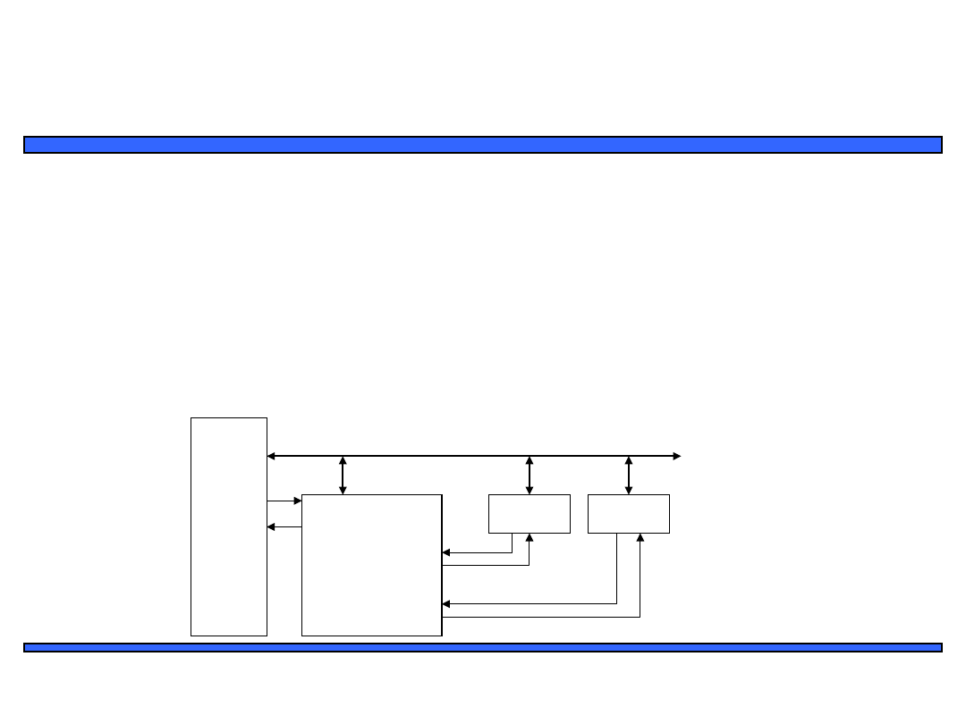
Arbitration: Priority arbiter
• Consider the situation where multiple peripherals request service
from single resource (e.g., microprocessor, DMA controller)
simultaneously - which gets serviced first?
• Priority
arbiter
– Single-purpose processor
– Peripherals make requests to arbiter, arbiter makes requests to
resource
– Arbiter connected to system bus for configuration only
Micro-
processo
r
Priority
arbiter
Periphera
l1
System bus
Int
3
5
7
Int
a
Periphera
l2
Ireq1
Iack2
Iack1
Ireq2
2
2
6
51
Embedded Systems Design: A Unified
Hardware/Software Introduction,
(c) 2000
Vahid/Givargis
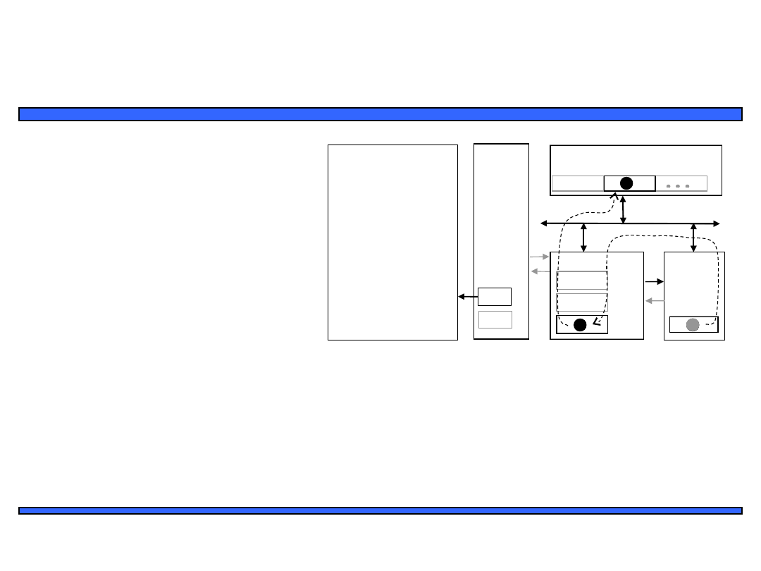
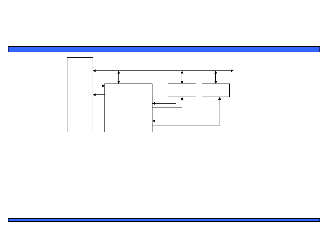
Arbitration using a priority arbiter
1.
1. Microprocessor is executing its program.
2.
2. Peripheral1 needs servicing so asserts Ireq1. Peripheral2 also needs
servicing so asserts Ireq2.
3.
3. Priority arbiter sees at least one Ireq input asserted, so asserts Int.
4.
4. Microprocessor stops executing its program and stores its state.
5.
5. Microprocessor asserts Inta.
6.
6. Priority arbiter asserts Iack1 to acknowledge Peripheral1.
7.
7. Peripheral1 puts its interrupt address vector on the system bus
8.
8. Microprocessor jumps to the address of ISR read from data bus, ISR
executes and returns
9.
(and completes handshake with arbiter).
10.
9. Microprocessor resumes executing its program.
Micro-
processo
r
Priority
arbiter
Periphera
l1
System bus
Int
3
5
7
Int
a
Periphera
l2
Ireq1
Iack2
Iack1
Ireq2
2
2
6

52
Embedded Systems Design: A Unified
Hardware/Software Introduction,
(c) 2000
Vahid/Givargis
Arbitration: Priority arbiter
• Types of priority
• Fixed priority
– each peripheral has unique rank
– highest rank chosen first with simultaneous requests
– preferred when clear difference in rank between
peripherals
• Rotating priority (round-robin)
– priority changed based on history of servicing
– better distribution of servicing especially among
peripherals with similar priority demands
53
Embedded Systems Design: A Unified
Hardware/Software Introduction,
(c) 2000
Vahid/Givargis
Arbitration: Daisy-chain arbitration
• Arbitration done by peripherals
– Built into peripheral or external logic added
• req input and ack output added to each peripheral
• Peripherals connected to each other in daisy-chain manner
– One peripheral connected to resource, all others connected “upstream”
– Peripheral’s req flows “downstream” to resource, resource’s ack flows
“upstream” to requesting peripheral
– Closest peripheral has highest priority
P
System bus
Int
Inta
Peripheral1
Ack_in Ack_out
Req_ou
t
Req_i
n
Peripheral2
Ack_in Ack_ou
t
Req_ou
t
Req_i
n
Daisy-chain aware peripherals
0
54
Embedded Systems Design: A Unified
Hardware/Software Introduction,
(c) 2000
Vahid/Givargis
Arbitration: Daisy-chain arbitration
• Pros/cons
– Easy to add/remove peripheral - no system
redesign needed
– Does not support rotating priority
– One broken peripheral can cause loss of access
to other peripherals
P
System bus
Int
Inta
Peripheral1
Ack_i
n
Ack_ou
t
Req_o
ut
Req_i
n
Peripheral2
Ack_i
n
Ack_o
ut
Req_o
ut
Req_i
n
Daisy-chain aware peripherals
0
Micro-
process
or
Priority
arbiter
Peripher
al1
System bus
Int
Int
a
Peripher
al2
Ireq
1
Iack
2
Iack
1
Ireq
2

55
Embedded Systems Design: A Unified
Hardware/Software Introduction,
(c) 2000
Vahid/Givargis
Network-oriented arbitration
• When multiple microprocessors share a bus
(sometimes called a network)
– Arbitration typically built into bus protocol
– Separate processors may try to write
simultaneously causing collisions
• Data must be resent
• Don’t want to start sending again at same time
– statistical methods can be used to reduce chances
• Typically used for connecting multiple distant
chips
– Trend – use to connect multiple on-chip processors
56
Embedded Systems Design: A Unified
Hardware/Software Introduction,
(c) 2000
Vahid/Givargis
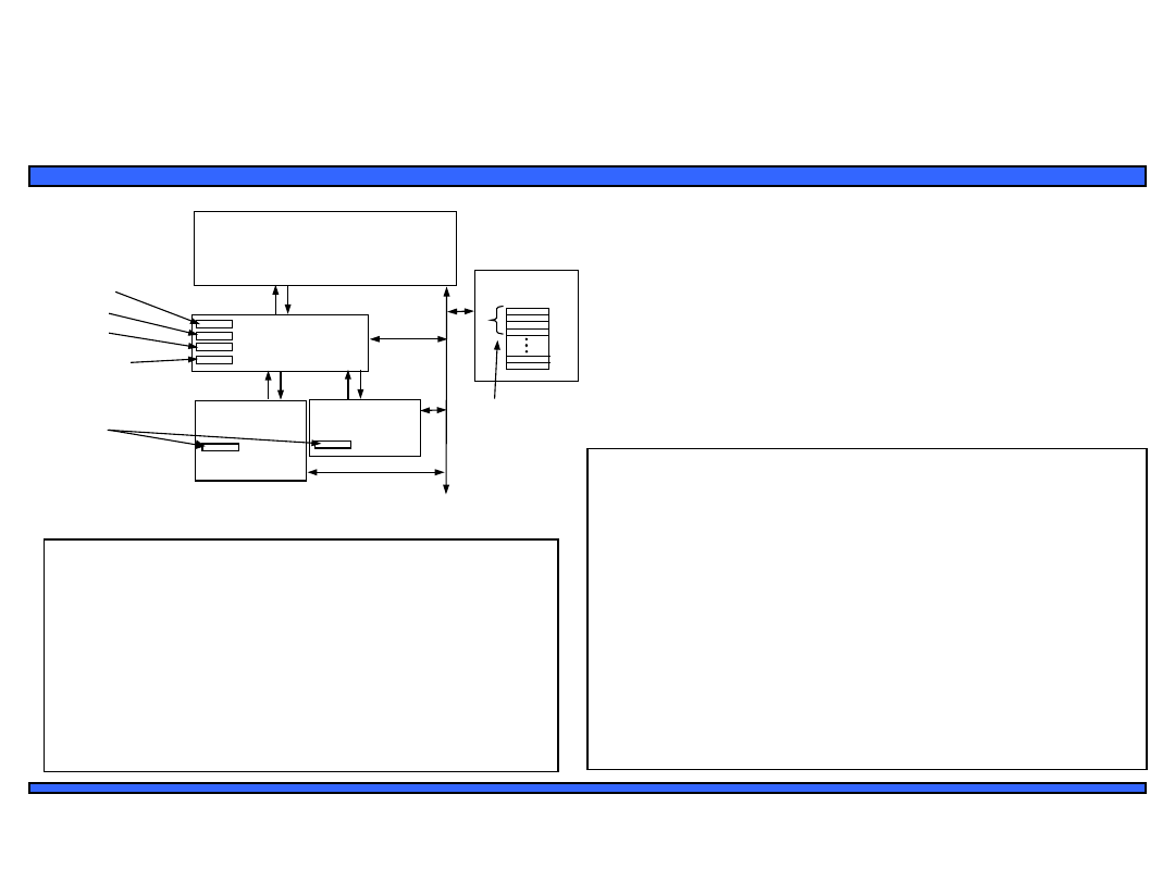
Jump Table
Me
mo
ry B
us
Processor
Peripheral
1
Peripheral
2
Priority Arbiter
MASK
IDX0
IDX1
ENABLE
DATA
MEMORY
void main() {
InitializePeripherals();
for(;;) {} // main program goes here
}
unsigned char ARBITER_MASK_REG
_at_ 0xfff0;
unsigned char ARBITER_CH0_INDEX_REG
_at_ 0xfff1;
unsigned char ARBITER_CH1_INDEX_REG
_at_ 0xfff2;
unsigned char ARBITER_ENABLE_REG
_at_ 0xfff3;
unsigned char PERIPHERAL1_DATA_REG
_at_ 0xffe0;
unsigned char PERIPHERAL2_DATA_REG
_at_ 0xffe1;
unsigned void* INTERRUPT_LOOKUP_TABLE[256] _at_ 0x0100;
void Peripheral1_ISR(void) {
unsigned char data;
data = PERIPHERAL1_DATA_REG;
// do something with the data
}
void Peripheral2_ISR(void) {
unsigned char data;
data = PERIPHERAL2_DATA_REG;
// do something with the data
}
void InitializePeripherals(void) {
ARBITER_MASK_REG = 0x03; // enable both channels
ARBITER_CH0_INDEX_REG = 13;
ARBITER_CH1_INDEX_REG = 17;
INTERRUPT_LOOKUP_TABLE[13] = (void*)Peripheral1_ISR;
INTERRUPT_LOOKUP_TABLE[17] = (void*)Peripheral2_ISR;
ARBITER_ENABLE_REG = 1;
}
Example: Vectored interrupt using
an interrupt table
•
Fixed priority: i.e., Peripheral1 has highest priority
•
Keyword “_at_” followed by memory address forces
compiler to place variables in specific memory
locations
–
e.g., memory-mapped registers in arbiter, peripherals
•
A peripheral’s index into interrupt table is sent to
memory-mapped register in arbiter
•
Peripherals receive external data and raise
interrupt
57
Embedded Systems Design: A Unified
Hardware/Software Introduction,
(c) 2000
Vahid/Givargis
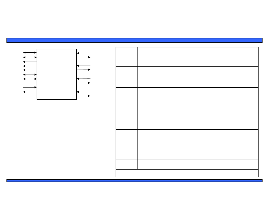
Intel 8237 DMA controller
Intel 8237
D[7..0]
A[19..0
]
ALE
MEMR
MEMW
IOR
IOW
HLDA
HRQ
REQ 0
ACK 0
REQ 1
ACK 1
REQ 2
ACK 2
REQ 3
ACK 3
Signal
Description
D[7..0]
These wires are connected to the system bus (ISA) and are used by the
microprocessor to write to the internal registers of the 8237.
A[19..0]
These wires are connected to the system bus (ISA) and are used by the DMA to
issue the memory location where the transferred data is to be written to. The 8237 is
also addressed by the micro-processor through the lower bits of these address lines.
ALE*
This is the address latch enable signal. The 8237 use this signal when driving the
system bus (ISA).
MEMR*
This is the memory write signal issued by the 8237 when driving the system bus
(ISA).
MEMW*
This is the memory read signal issued by the 8237 when driving the system bus (ISA).
IOR*
This is the I/O device read signal issued by the 8237 when driving the system bus
(ISA) in order to read a byte from an I/O device
IOW*
This is the I/O device write signal issued by the 8237 when driving the system bus
(ISA) in order to write a byte to an I/O device.
HLDA
This signal (hold acknowledge) is asserted by the microprocessor to signal that it has
relinquished the system bus (ISA).
HRQ
This signal (hold request) is asserted by the 8237 to signal to the microprocessor a
request to relinquish the system bus (ISA).
REQ 0,1,2,3 An attached device to one of these channels asserts this signal to request a DMA
transfer.
ACK 0,1,2,3 The 8237 asserts this signal to grant a DMA transfer to an attached device to one of
these channels.
*See the ISA bus description in this chapter for complete details.
58
Embedded Systems Design: A Unified
Hardware/Software Introduction,
(c) 2000
Vahid/Givargis
Intel 8259 programmable priority
controller
Intel 8259
D[7..0]
A[0..0]
RD
WR
INT
INTA
CAS[2..0]
SP/EN
IR0
IR1
IR2
IR3
IR4
IR5
IR6
IR7
Signal
Description
D[7..0]
These wires are connected to the system bus and are used by the microprocessor to
write or read the internal registers of the 8259.
A[0..0]
This pin actis in cunjunction with WR/RD signals. It is used by the 8259 to decipher
various command words the microprocessor writes and status the microprocessor
wishes to read.
WR
When this write signal is asserted, the 8259 accepts the command on the data line, i.e.,
the microprocessor writes to the 8259 by placing a command on the data lines and
asserting this signal.
RD
When this read signal is asserted, the 8259 provides on the data lines its status, i.e., the
microprocessor reads the status of the 8259 by asserting this signal and reading the data
lines.
INT
This signal is asserted whenever a valid interrupt request is received by the 8259, i.e., it
is used to interrupt the microprocessor.
INTA
This signal, is used to enable 8259 interrupt-vector data onto the data bus by a sequence
of interrupt acknowledge pulses issued by the microprocessor.
IR
0,1,2,3,4,5,6,7
An interrupt request is executed by a peripheral device when one of these signals is
asserted.
CAS[2..0]
These are cascade signals to enable multiple 8259 chips to be chained together.
SP/EN
This function is used in conjunction with the CAS signals for cascading purposes.
59
Embedded Systems Design: A Unified
Hardware/Software Introduction,
(c) 2000
Vahid/Givargis
Multilevel bus architectures
• Processor-local bus
– High speed, wide, most frequent
communication
– Connects microprocessor, cache,
memory controllers, etc.
• Peripheral bus
– Lower speed, narrower, less
frequent communication
– Typically industry standard bus
(ISA, PCI) for portability
Processor-local bus
Micro-
process
or
Cache
Memory
controll
er
DMA
controll
er
Bridge
Peripher
al
Peripher
al
Peripher
al
Peripheral
bus
• Don’t want one bus for all communication
– Peripherals would need high-speed, processor-specific bus
interface
• excess gates, power consumption, and cost; less portable
– Too many peripherals slows down bus
• Bridge
– Single-purpose processor converts communication between
busses

60
Embedded Systems Design: A Unified
Hardware/Software Introduction,
(c) 2000
Vahid/Givargis
Advanced communication
principles
• Layering
– Break complexity of communication protocol into pieces easier to
design and understand
– Lower levels provide services to higher level
• Lower level might work with bits while higher level might work with
packets of data
– Physical layer
• Lowest level in hierarchy
• Medium to carry data from one actor (device or node) to another
• Parallel communication
– Physical layer capable of transporting multiple bits of data
• Serial communication
– Physical layer transports one bit of data at a time
• Wireless communication
– No physical connection needed for transport at physical layer

61
Embedded Systems Design: A Unified
Hardware/Software Introduction,
(c) 2000
Vahid/Givargis
Parallel communication
• Multiple data, control, and possibly power wires
– One bit per wire
• High data throughput with short distances
• Typically used when connecting devices on same
IC or same circuit board
– Bus must be kept short
• long parallel wires result in high capacitance values which
requires more time to charge/discharge
• Data misalignment between wires increases as length
increases
• Higher cost, bulky

62
Embedded Systems Design: A Unified
Hardware/Software Introduction,
(c) 2000
Vahid/Givargis
Serial communication
• Single data wire, possibly also control and power
wires
• Words transmitted one bit at a time
• Higher data throughput with long distances
– Less average capacitance, so more bits per unit of time
• Cheaper, less bulky
• More complex interfacing logic and communication
protocol
– Sender needs to decompose word into bits
– Receiver needs to recompose bits into word
– Control signals often sent on same wire as data increasing
protocol complexity

63
Embedded Systems Design: A Unified
Hardware/Software Introduction,
(c) 2000
Vahid/Givargis
Wireless communication
• Infrared (IR)
– Electronic wave frequencies just below visible light spectrum
– Diode emits infrared light to generate signal
– Infrared transistor detects signal, conducts when exposed to
infrared light
– Cheap to build
– Need
line of sight, limited range
• Radio frequency (RF)
– Electromagnetic wave frequencies in radio spectrum
– Analog circuitry and antenna needed on both sides of
transmission
– Line of sight not needed, transmitter power determines range

64
Embedded Systems Design: A Unified
Hardware/Software Introduction,
(c) 2000
Vahid/Givargis
Error detection and correction
• Often part of bus protocol
• Error detection: ability of receiver to detect errors during
transmission
• Error correction: ability of receiver and transmitter to
cooperate to correct problem
– Typically done by acknowledgement/retransmission protocol
• Bit error: single bit is inverted
• Burst of bit error: consecutive bits received incorrectly
• Parity: extra bit sent with word used for error detection
– Odd parity: data word plus parity bit contains odd number of 1’s
– Even parity: data word plus parity bit contains even number of 1’s
– Always detects single bit errors, but not all burst bit errors
• Checksum: extra word sent with data packet of multiple words
– e.g., extra word contains XOR sum of all data words in packet

65
Embedded Systems Design: A Unified
Hardware/Software Introduction,
(c) 2000
Vahid/Givargis
Serial protocols: I
2
C
• I
2
C (Inter-IC)
– Two-wire serial bus protocol developed by Philips
Semiconductors nearly 20 years ago
– Enables peripheral ICs to communicate using simple
communication hardware
– Data transfer rates up to 100 kbits/s and 7-bit addressing
possible in normal mode
– 3.4 Mbits/s and 10-bit addressing in fast-mode
– Common devices capable of interfacing to I
2
C bus:
• EPROMS, Flash, and some RAM memory, real-time clocks,
watchdog timers, and microcontrollers
66
Embedded Systems Design: A Unified
Hardware/Software Introduction,
(c) 2000
Vahid/Givargis
I2C bus structure
SCL
SDA
Micro-
controller
(master)
EEPROM
(servant)
Temp.
Sensor
(servant)
LCD-
controller
(servant)
< 400
pF
Addr=0x01 Addr=0x02
Addr=0x03
D
C
S
T
A
R
T
A
6
A
5
A
0
R
/
w
A
C
K
D
8
D
7
D
0
A
C
K
S
T
O
P
From
Serva
nt
From
receiv
er
Typical read/write cycle
SDA
SCL
SDA
SCL
SDA
SCL
SDA
SCL
Start
condition
Sending 0
Sending 1
Stop
condition

67
Embedded Systems Design: A Unified
Hardware/Software Introduction,
(c) 2000
Vahid/Givargis
Serial protocols: CAN
• CAN (Controller area network)
– Protocol for real-time applications
– Developed by Robert Bosch GmbH
– Originally for communication among components of cars
– Applications now using CAN include:
• elevator controllers, copiers, telescopes, production-line control
systems, and medical instruments
– Data transfer rates up to 1 Mbit/s and 11-bit addressing
– Common devices interfacing with CAN:
• 8051-compatible 8592 processor and standalone CAN controllers
– Actual physical design of CAN bus not specified in protocol
• Requires devices to transmit/detect dominant and recessive signals to/from
bus
• e.g., ‘1’ = dominant, ‘0’ = recessive if single data wire used
• Bus guarantees dominant signal prevails over recessive signal if asserted
simultaneously

68
Embedded Systems Design: A Unified
Hardware/Software Introduction,
(c) 2000
Vahid/Givargis
Serial protocols: FireWire
• FireWire (a.k.a. I-Link, Lynx, IEEE 1394)
– High-performance serial bus developed by Apple Computer Inc.
– Designed for interfacing independent electronic components
• e.g., Desktop, scanner
– Data transfer rates from 12.5 to 400 Mbits/s, 64-bit addressing
– Plug-and-play capabilities
– Packet-based layered design structure
– Applications using FireWire include:
• disk drives, printers, scanners, cameras
– Capable of supporting a LAN similar to Ethernet
• 64-bit address:
– 10 bits for network ids
,
1023 subnetworks
– 6 bits for node ids,
e
ach subnetwork can have 63 nodes
– 48 bits for memory address, each node can have
281 terabytes
of
distinct
locations

69
Embedded Systems Design: A Unified
Hardware/Software Introduction,
(c) 2000
Vahid/Givargis
Serial protocols: USB
• USB (Universal Serial Bus)
– Easier connection between PC and monitors, printers, digital speakers,
modems, scanners, digital cameras, joysticks, multimedia game equipment
– 2 data rates:
• 12 Mbps for increased bandwidth devices
• 1.5 Mbps for lower-speed devices (joysticks, game pads)
– Tiered star topology can be used
• One USB device (hub) connected to PC
– hub can be embedded in devices like monitor, printer, or keyboard or can be
standalone
• Multiple USB devices can be connected to hub
• Up to 127 devices can be connected like this
– USB host controller
• Manages and controls bandwidth and driver software required by each
peripheral
• Dynamically allocates power downstream according to devices
connected/disconnected

70
Embedded Systems Design: A Unified
Hardware/Software Introduction,
(c) 2000
Vahid/Givargis
Parallel protocols: PCI Bus
• PCI Bus (Peripheral Component Interconnect)
– High performance bus originated at Intel in the early 1990’s
– Standard adopted by industry and administered by PCISIG (PCI
Special Interest Group)
– Interconnects chips, expansion boards, processor memory
subsystems
– Data transfer rates of 127.2 to 508.6 Mbits/s and 32-bit
addressing
• Later extended to 64-bit while maintaining compatibility with 32-bit
schemes
– Synchronous bus architecture
– Multiplexed data/address lines

71
Embedded Systems Design: A Unified
Hardware/Software Introduction,
(c) 2000
Vahid/Givargis
Parallel protocols: ARM Bus
• ARM Bus
– Designed and used internally by ARM Corporation
– Interfaces with ARM line of processors
– Many IC design companies have own bus protocol
– Data transfer rate is a function of clock speed
• If clock speed of bus is X, transfer rate = 16 x X bits/s
– 32-bit addressing

72
Embedded Systems Design: A Unified
Hardware/Software Introduction,
(c) 2000
Vahid/Givargis
Wireless protocols: IrDA
• IrDA
– Protocol suite that supports short-range point-to-point
infrared data transmission
– Created and promoted by the Infrared Data Association
(IrDA)
– Data transfer rate of 9.6 kbps and 4 Mbps
– IrDA hardware deployed in notebook computers,
printers, PDAs, digital cameras, public phones, cell
phones
– Lack of suitable drivers has slowed use by applications
– Windows 2000/98 now include support
– Becoming available on popular embedded OS’s

73
Embedded Systems Design: A Unified
Hardware/Software Introduction,
(c) 2000
Vahid/Givargis
Wireless protocols: Bluetooth
• Bluetooth
– New, global standard for wireless connectivity
– Based on low-cost, short-range radio link
– Connection established when within 10 meters of each
other
– No line-of-sight required
• e.g., Connect to printer in another room

74
Embedded Systems Design: A Unified
Hardware/Software Introduction,
(c) 2000
Vahid/Givargis
Wireless Protocols: IEEE 802.11
• IEEE 802.11
– Proposed standard for wireless LANs
– Specifies parameters for PHY and MAC layers of network
• PHY layer
– physical layer
– handles transmission of data between nodes
– provisions for data transfer rates of 1 or 2 Mbps
– operates in 2.4 to 2.4835 GHz frequency band (RF)
– or 300 to 428,000 GHz (IR)
• MAC layer
– medium access control layer
– protocol responsible for maintaining order in shared medium
– collision avoidance/detection

75
Embedded Systems Design: A Unified
Hardware/Software Introduction,
(c) 2000
Vahid/Givargis
Chapter Summary
• Basic protocol concepts
– Actors, direction, time multiplexing, control methods
• General-purpose processors
– Port-based or bus-based I/O
– I/O addressing: Memory mapped I/O or Standard I/O
– Interrupt handling: fixed or vectored
– Direct memory access
• Arbitration
– Priority arbiter (fixed/rotating) or daisy chain
• Bus hierarchy
• Advanced communication
– Parallel vs. serial, wires vs. wireless, error detection/correction,
layering
– Serial protocols: I
2
C, CAN, FireWire, and USB; Parallel: PCI and ARM.
– Serial wireless protocols: IrDA, Bluetooth, and IEEE 802.11.
Document Outline
- Chapter 6 Interfacing
- Outline
- Introduction
- A simple bus
- Ports
- Timing Diagrams
- Basic protocol concepts
- Basic protocol concepts: control methods
- A strobe/handshake compromise
- ISA bus protocol – memory access
- Microprocessor interfacing: I/O addressing
- Compromises/extensions
- Types of bus-based I/O: memory-mapped I/O and standard I/O
- Memory-mapped I/O vs. Standard I/O
- ISA bus
- A basic memory protocol
- A more complex memory protocol
- Microprocessor interfacing: interrupts
- Slide 19
- Interrupt-driven I/O using fixed ISR location
- Interrupt-driven I/O using fixed ISR location
- Slide 22
- Slide 23
- Slide 24
- Slide 25
- Interrupt-driven I/O using vectored interrupt
- Interrupt-driven I/O using vectored interrupt
- Slide 28
- Slide 29
- Slide 30
- Slide 31
- Slide 32
- Interrupt address table
- Additional interrupt issues
- Direct memory access
- Peripheral to memory transfer without DMA, using vectored interrupt
- PowerPoint Presentation
- Peripheral to memory transfer without DMA, using vectored interrupt
- Slide 39
- Peripheral to memory transfer without DMA, using vectored interrupt (cont’)
- Slide 41
- Slide 42
- Peripheral to memory transfer with DMA
- Peripheral to memory transfer with DMA (cont’)
- Slide 45
- Slide 46
- Slide 47
- Slide 48
- ISA bus DMA cycles
- Arbitration: Priority arbiter
- Arbitration using a priority arbiter
- Slide 52
- Arbitration: Daisy-chain arbitration
- Slide 54
- Network-oriented arbitration
- Example: Vectored interrupt using an interrupt table
- Intel 8237 DMA controller
- Intel 8259 programmable priority controller
- Multilevel bus architectures
- Advanced communication principles
- Parallel communication
- Serial communication
- Wireless communication
- Error detection and correction
- Serial protocols: I2C
- I2C bus structure
- Serial protocols: CAN
- Serial protocols: FireWire
- Serial protocols: USB
- Parallel protocols: PCI Bus
- Parallel protocols: ARM Bus
- Wireless protocols: IrDA
- Wireless protocols: Bluetooth
- Wireless Protocols: IEEE 802.11
- Chapter Summary
Wyszukiwarka
Podobne podstrony:
CH6
Ch6 E4
Ch6 Pgs219 242
ch6
ch6
cisco2 ch6 focus B5BPVOCQFZHFLVQCHJBGE44PTKTAEUAFQWKNNWQ
Beginning smartphone development CH6
cisco2 ch6 vocab IWY4ZIDR4ERMF3TLNEL6RP6FA7AK2SQL7RQWQBY
ch6
Ch6 E7
ch6 zajzzv3woe5iy6niljqfqtsxijfkp7hzz7zp5wi ZAJZZV3WOE5IY6NILJQFQTSXIJFKP7HZZ7ZP5WI
Ch6 Parametric Sketches
Ch6 SocialImplicationsOfForestEnergyProduction
Ch6 E2
Ch6 E6
Ch6
cisco2 ch6 concept JJMG4YPKD5AN442ISO6S4CWJEQFD2QRRMFYLNWI
Ch6 E1
więcej podobnych podstron