
http://www.instructables.com/id/making_vise_clamps_on_the_milling_machine/
making vise clamps on the milling machine
on March 4, 2008
Table of Contents
License: Public Domain Dedication (pd)
.
.
.
.
.
.
.
.
.
.
.
.
.
.
.
.
.
.
.
.
.
.
.
.
.
.
.
.
.
.
.
.
.
.
.
.
.
.
.
.
.
.
.
.
.
.
.
.
.
.
.
.
.
.
.
.
.
.
.
.
.
.
.
.
.
.
.
.
.
.
.
.
.
.
.
.
.
.
.
.
.
.
.
.
.
.
.
.
.
.
.
.
Intro: Making vise clamps on the milling machine
.
.
.
.
.
.
.
.
.
.
.
.
.
.
.
.
.
.
.
.
.
.
.
.
.
.
.
.
.
.
.
.
.
.
.
.
.
.
.
.
.
.
.
.
.
.
.
.
.
.
.
.
.
.
.
.
.
.
.
.
.
.
.
.
.
.
.
.
.
.
.
.
.
.
.
.
.
.
.
.
.
.
.
.
.
.
.
.
.
.
.
.
.
.
.
.
.
.
.
.
.
.
.
.
.
.
.
.
.
.
.
.
.
.
.
.
.
.
.
.
.
.
.
.
.
.
.
.
.
.
.
.
.
.
.
.
.
.
.
.
.
.
.
.
.
.
.
.
.
.
.
.
.
.
.
.
.
.
.
.
.
.
.
.
.
.
.
.
.
.
.
.
.
.
.
.
.
.
.
.
.
.
.
.
.
.
.
.
.
.
.
.
.
.
.
.
.
.
.
.
.
.
.
.
.
.
.
.
.
.
.
.
.
.
.
.
.
.
.
.
.
.
.
.
.
.
.
.
.
.
.
.
.
.
.
.
.
.
.
.
.
.
.
.
.
.
.
.
.
.
.
.
.
.
.
.
.
.
.
.
.
.
.
.
.
.
.
.
.
.
.
.
.
.
.
.
.
.
.
.
.
.
.
.
.
.
.
.
.
.
.
.
.
.
.
.
.
.
.
.
.
.
step 2: Rough cut the angle iron
.
.
.
.
.
.
.
.
.
.
.
.
.
.
.
.
.
.
.
.
.
.
.
.
.
.
.
.
.
.
.
.
.
.
.
.
.
.
.
.
.
.
.
.
.
.
.
.
.
.
.
.
.
.
.
.
.
.
.
.
.
.
.
.
.
.
.
.
.
.
.
.
.
.
.
.
.
.
.
.
.
.
.
.
.
.
.
.
.
.
.
.
.
.
.
.
.
.
step 3: Clean up the long edges
.
.
.
.
.
.
.
.
.
.
.
.
.
.
.
.
.
.
.
.
.
.
.
.
.
.
.
.
.
.
.
.
.
.
.
.
.
.
.
.
.
.
.
.
.
.
.
.
.
.
.
.
.
.
.
.
.
.
.
.
.
.
.
.
.
.
.
.
.
.
.
.
.
.
.
.
.
.
.
.
.
.
.
.
.
.
.
.
.
.
.
.
.
.
.
.
.
.
.
.
.
.
.
.
.
.
.
.
.
.
.
.
.
.
.
.
.
.
.
.
.
.
.
.
.
.
.
.
.
.
.
.
.
.
.
.
.
.
.
.
.
.
.
.
.
.
.
.
.
.
.
.
.
.
.
.
.
.
.
.
.
.
.
.
.
.
.
.
.
.
.
.
.
.
.
.
.
.
.
.
.
.
.
.
.
.
.
.
.
.
.
.
.
.
.
.
.
.
.
step 5: All the facing is done
.
.
.
.
.
.
.
.
.
.
.
.
.
.
.
.
.
.
.
.
.
.
.
.
.
.
.
.
.
.
.
.
.
.
.
.
.
.
.
.
.
.
.
.
.
.
.
.
.
.
.
.
.
.
.
.
.
.
.
.
.
.
.
.
.
.
.
.
.
.
.
.
.
.
.
.
.
.
.
.
.
.
.
.
.
.
.
.
.
.
.
.
.
.
.
.
.
.
.
.
.
.
.
.
.
.
.
.
.
.
.
.
.
.
.
.
.
.
.
.
.
.
.
.
.
.
.
.
.
.
.
.
.
.
.
.
.
.
.
.
.
.
.
.
.
.
.
.
.
.
.
.
.
.
.
.
.
.
.
.
.
.
.
.
.
.
.
.
.
.
.
.
.
.
.
.
.
.
.
.
.
.
.
.
.
.
.
.
.
.
.
.
.
.
.
.
.
.
.
.
.
.
.
.
.
.
.
.
.
.
.
.
.
.
.
.
.
.
.
.
.
.
.
.
.
.
.
.
.
.
.
.
.
.
.
.
.
.
.
.
.
.
.
.
.
.
.
.
.
.
.
.
.
.
.
.
.
.
.
.
.
.
.
.
.
.
.
.
.
.
.
.
.
.
.
.
.
.
.
.
.
.
.
.
.
.
.
.
.
.
.
.
.
.
.
.
.
.
.
.
.
.
.
.
.
.
.
.
.
.
.
.
.
.
.
.
.
.
.
.
.
.
.
.
.
.
.
.
.
.
.
.
.
.
.
.
.
.
.
.
.
.
.
.
.
.
.
.
.
.
.
.
.
.
.
.
.
.
.
.
.
.
.
.
.
.
.
.
.
.
.
.
.
.
.
.
.
.
.
.
.
.
.
.
.
.
.
.
.
.
.
.
.
.
.
.
.
.
.
.
.
.
.
.
.
.
.
.
.
.
.
.
.
.
.
.
.
.
.
.
.
.
.
.
.
.
.
.
.
.
.
.
.
.
.
.
.
.
.
.
.
.
.
.
.
.
.
.
.
.
.
.
.
.
.
.
.
.
.
.
.
.
.
.
.
.
.
.
.
.
.
.
.
.
.
.
.
.
.
.
.
.
.
.
.
.
.
.
.
.
.
.
.
.
.
.
.
.
.
.
.
.
.
.
.
.
.
.
.
.
.
.
.
.
.
.
.
.
.
.
.
.
.
.
.
.
.
.
.
.
.
.
.
.
.
.
.
.
.
.
.
.
.
.
.
.
.
.
.
.
.
.
.
.
.
.
.
.
.
.
.
.
.
.
.
.
.
.
.
.
.
.
.
.
.
.
.
.
.
.
.
.
.
.
.
.
.
.
.
.
.
.
.
.
.
.
.
.
.
.
.
.
.
.
.
.
.
.
.
.
.
.
.
.
.
.
.
.
.
.
.
.
.
.
.
.
.
.
.
.
.
.
.
.
.
.
.
.
.
.
.
.
.
.
.
.
.
.
.
.
.
.
.
.
.
.
.
.
.
.
.
.
.
.
.
.
.
.
.
.
.
.
.
.
.
.
.
.
.
.
.
.
.
.
.
.
.
.
.
.
.
.
.
.
.
.
.
.
.
.
.
.
.
.
.
.
.
.
.
.
.
.
.
.
.
.
.
.
.
.
.
.
.
.
.
.
.
.
.
.
.
.
.
.
.
.
.
.
.
.
.
.
.
.
.
.
.
.
.
.
.
.
.
.
.
.
.
.
.
.
.
.
.
.
.
.
.
.
.
.
.
.
.
.
.
.
.
.
.
.
.
.
.
.
.
.
.
.
.
.
.
.
.
.
.
.
.
.
.
.
.
.
.
.
.
.
.
.
.
.
.
.
.
.
.
.
.
.
.
.
.
.
.
.
.
.
.
.
.
.
.
.
.
.
.
.
.
.
.
.
.
.
.
.
.
.
.
.
.
.
.
.
.
.
.
.
.
.
.
.
.
.
.
.
.
.
.
.
.
.
.
.
.
.
.
.
.
.
.
.
.
.
.
.
.
.
.
.
.
.
.
.
.
.
.
.
.
.
.
.
.
.
.
.
.
.
.
.
.
.
.
.
.
.
.
.
.
.
.
.
.
.
.
.
.
.
.
.
.
.
.
.
.
.
.
.
.
.
.
.
.
.
.
.
.
.
.
.
.
.
.
.
.
.
.
.
.
.
.
.
.
.
.
.
.
.
.
.
.
.
.
.
.
.
.
.
.
.
.
.
.
.
.
.
.
.
.
.
.
.
.
.
.
.
.
.
.
.
.
.
.
.
.
.
.
.
.
.
.
.
.
.
.
.
.
.
.
.
.
.
.
.
.
.
.
.
.
.
.
.
.
.
.
.
.
.
.
.
.
.
.
.
.
.
.
.
.
.
.
.
.
.
.
.
.
.
.
.
.
.
.
.
.
.
.
http://www.instructables.com/id/making_vise_clamps_on_the_milling_machine/
License:
Intro:
Making vise clamps on the milling machine
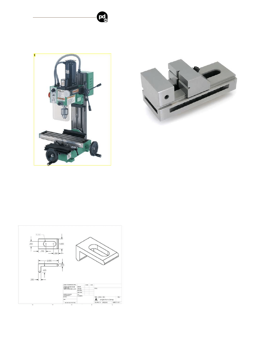
This is a build log of making a simple clamp for holding a milling vise on a milling table. I'm a novice machinist, so there might be some mistakes or errors here and there.
and imported and sold in the US by
,
, etc.
The milling vise is a small screwless toolmaker's vise with clamping slots, sold by
, etc.
Image Notes
1. It's so cute and *little*!
step 1:
The design
The bottom surface of the vise's clamping slot is about 0.595 inch above the table, and the top surface of the clamping slot is about 0.300 inch above the bottom surface.
I'm making the clamps from some scrap angle iron. The stock is 0.25 inch thick. Each side is about 2 inches long (from the outside corner of the angle to the end of the
"leg").
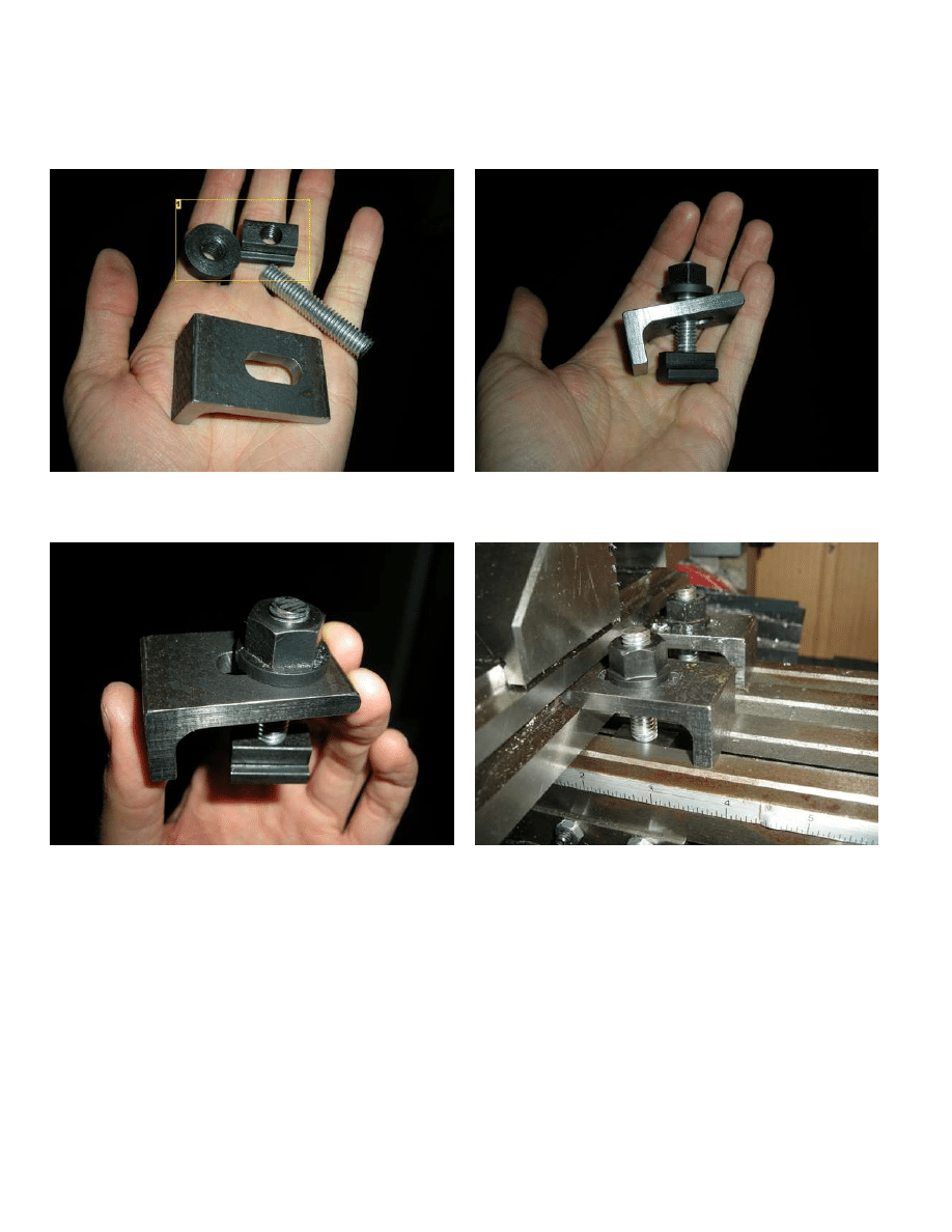
Additional stuff that's needed that I'm not making is a T-nut, a flange nut, and about 2 inches of 3/8-16 threaded rod.
File Downloads
http://www.instructables.com/id/making_vise_clamps_on_the_milling_machine/
angle-iron-clamp.SLDDRW (355 KB)
[NOTE: When saving, if you see .tmp as the file ext, rename it to 'angle-iron-clamp.SLDDRW']
angle-iron-clamp.SLDPRT (171 KB)
[NOTE: When saving, if you see .tmp as the file ext, rename it to 'angle-iron-clamp.SLDPRT']
step 2:
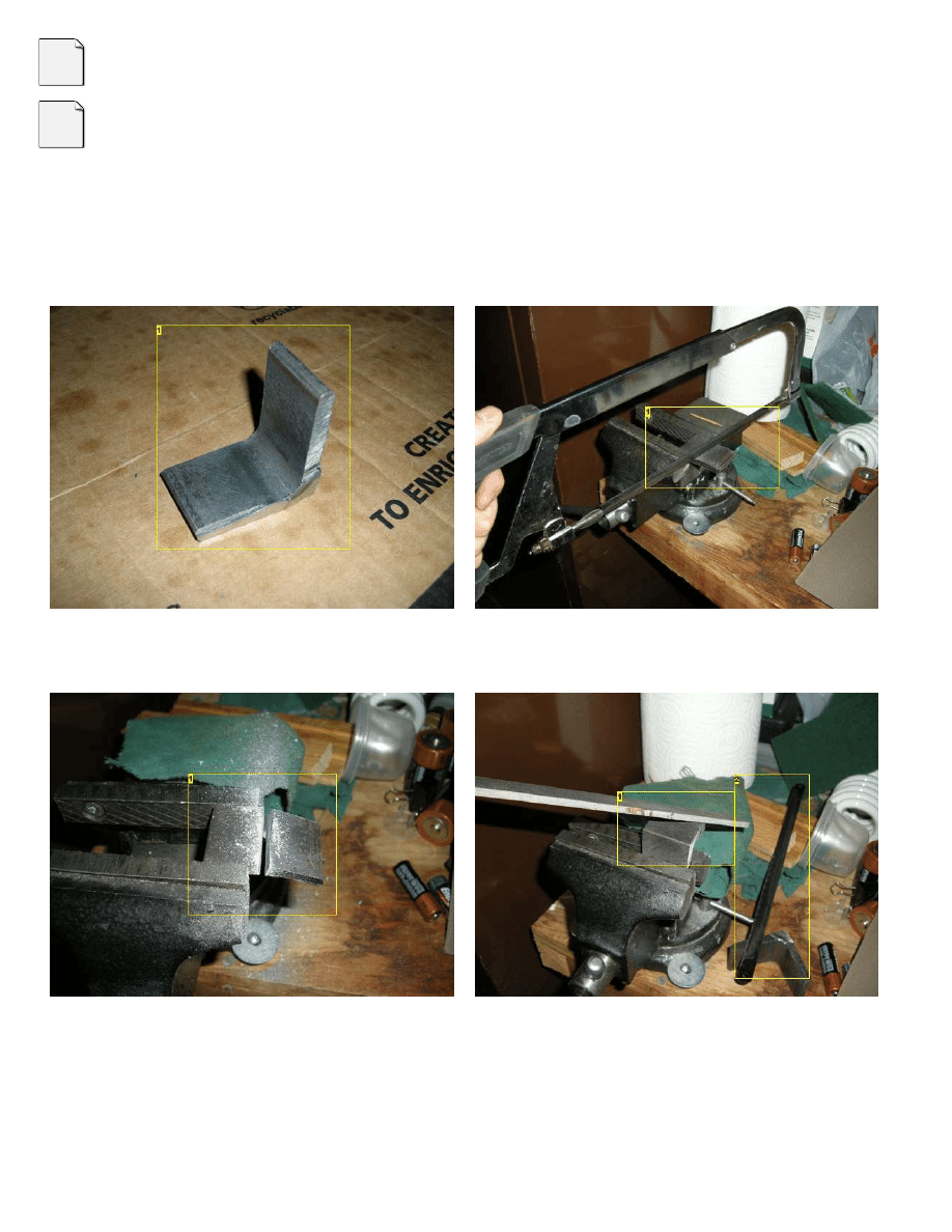
Rough cut the angle iron
I put an abrasive cut-off wheel on my wood-cutting compound miter saw and cut the angle iron on that. It cut fine, but it got hot enough to melt the plastic part of the saw's
table.... That made me feel kind of stupid, I hope no one notices.
Anyway, I cut about a 1 inch wide piece off the length of angle iron. The exact size is not very important.
Then I cut off part of one "leg" of the piece, this will be the foot of the clamp later (where it stands on the mill's table). I learned my lesson about the plastic-tabled saw and
made this cut with a hacksaw.
Image Notes
1. 1 inch wide or there about. The cut edges are very rough.
Image Notes
1. A sharp blade helps. I left enough metal on the workpiece to clean up the cut on
the mill later.
Image Notes
1. Almost there! Buy a band saw!
Image Notes
1. I filed off the burr to make it easier to hold in the milling vise later.
2. Throw away the dull blade.
http://www.instructables.com/id/making_vise_clamps_on_the_milling_machine/
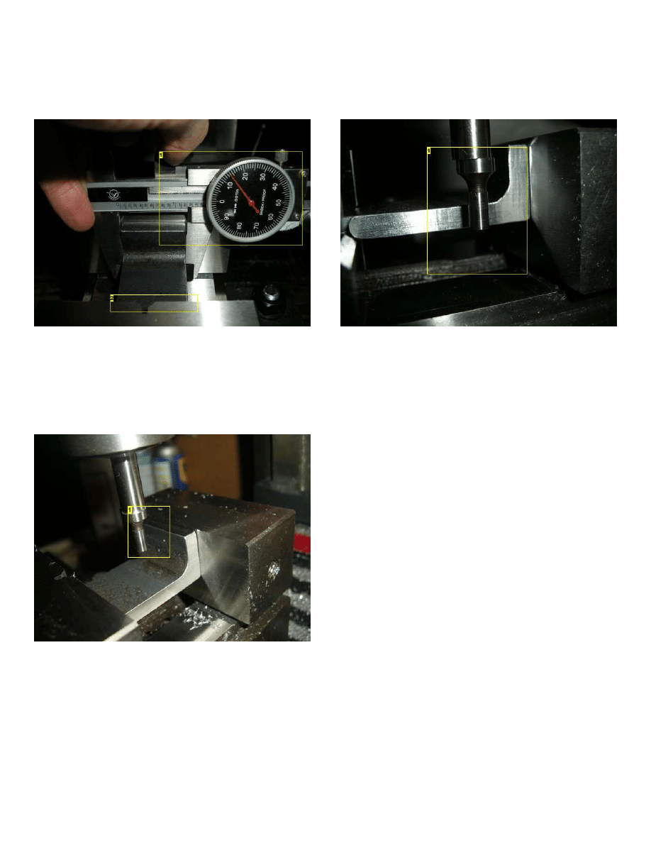
step 3:
Clean up the long edges
I set up the angle iron in the milling vise and milled the long cut edges nice & flat (& somewhat to size, though this dimension is not terribly important).
The pictures show the setup for milling the two long sides. The rounded end of the angle-iron fits into the horizontal V-groove in the movable jaw of the vise. The edge
that I'm milling is sticking out 1/4 inch or so past the vise jaws. This setup was plenty secure.
I eyeballed the workpiece to find the part that was sticking out the most, and gently touched off the cutter at that point. Then I started doing cutting passes in the Y
direction, front to back, so each pass was done in conventional milling mode (I'm staying away from climb milling for now). Each pass took off about 0.010 inches of
material, on whatever parts of the workpiece were sticking out. Eventually it cut along the whole face of the workpiece, and then I did a 0.005 inch finishing cut and called
it done.
I used a 3/4 inch 4-flute milling cutter spinning at something like 800 rpm. Feedrate was probably about 5 or 7 ipm. Depth of cut (of each cut) was about 0.010 inch. I
occasionally squirted WD-40 on the cutter and workpiece while cutting.
To mill the other long side I flipped the workpiece upside down (as shown in the second picture). The location of the V-groove in the vise jaw and the length of the foot
(the short leg of the angle iron) conspire to make this possible. If the dimensions hadn't worked out I could have kept the workpiece in the "foot-up" orientation and slid the
workpiece to the other side of the jaws.
Image Notes
1. The face that's sticking out is rough-cut and needs to be cleaned up and
squared.
2. The rounded front of the angle iron fits securely in the horizonal V in the
movable face of the jaw.
3. The old clamp, clearly inferior to the one I'm making...
Image Notes
1. The face after milling.
http://www.instructables.com/id/making_vise_clamps_on_the_milling_machine/
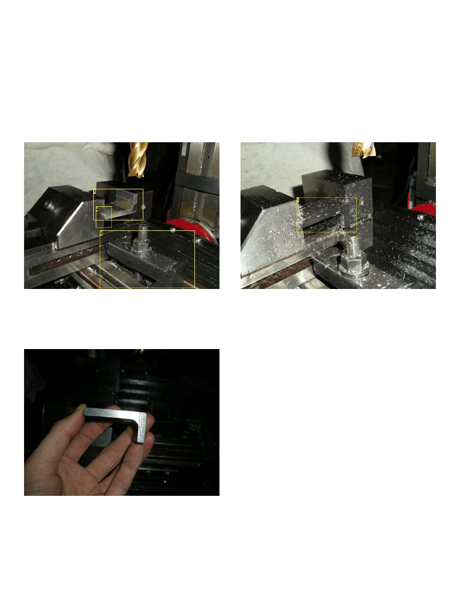
step 4:
Cleaning up the foot
Next I did the "foot" of the clamp, the part that rests on the milling table. This operation cleaned up the hacksaw job & established the height of the clamp. This is probably
the most important dimension, but even here there's room for some slop.
I clamped the "long leg" of the workpiece in the vise, being careful to clamp on the straight part of the angle iron, not up near the corner where the thickness changes. I
positioned the clamp near the center of the vice to keep the clamping force balanced and avoid twisting the movable jaw.
The desired length of the foot (per the drawing) is 0.875 inch. I knew I cut the foot longer than that with the hacksaw, so there is some spare stock at the end of the foot to
work with.
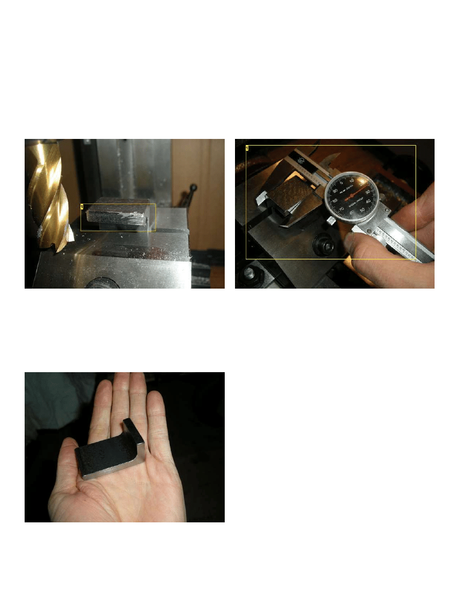
First I squared the bottom of the foot by skimming it with the cutter, just like I squared the long sides in step 3 (except along X in stead of along Y). I cut from the left of the
workpiece to the right, to stay with conventional milling.
Once it was flat along the whole bottom of the foot I measured the foot height with calipers (I wiped the reference surfaces with a rag so the swarf wouldnt throw off the
reading). This measurement told me how much material I had to remove. I took it off in 0.010 inch cuts until I got within about 0.020, then I measured again and took
shallow cuts until I got within 0.005 inch, then I called it good.
Image Notes
1. the right side is not getting cut yet, need to take another 0.005 inch or so off
Image Notes
1. Measuring the current height of the foot: 0.924 inch, need to remove 0.049 inch
more.
step 5:
All the facing is done
Here it is with all three faces in order and all the edges of those faces filed smooth.
Now it's all over but the slotting.
http://www.instructables.com/id/making_vise_clamps_on_the_milling_machine/
step 6:
Slotting setup
For the slotting, I set it up like this.
It's nice to have the workpiece roughly centered in the jaws, because it gives even clamping pressure, not so much twisting force on the movable jaw.
I want the slot in the middle of the clamp, so I measured the final, actual width of the clamp, located the edge, and positioned the spindle at the X axis center of the clamp.
Lock the X gibs here, we'll just be moving in Y and Z for a while.
Image Notes
1. 1.214, that's about 1.000 right?
2. Again the round front of the long leg is in the horizontal V-groove of the movable
jaw.
Image Notes
1. Locating the edge of the clamp.
step 7:
Locate the foot
Touch off against the "inside" of the foot. Remember to compensate for the radius of the edge finder.
Image Notes
1. Touch off against the "inside" of the foot.
http://www.instructables.com/id/making_vise_clamps_on_the_milling_machine/
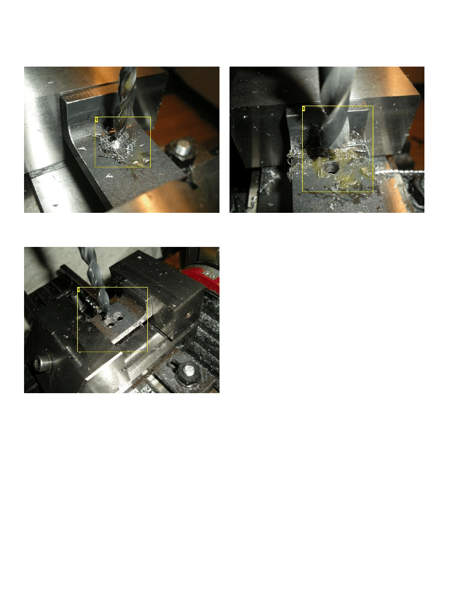
step 8:
Pre-drill the slot
Drill bits are easier to sharpen than milling cutters, so I drilled holes to hog out most of the metal for the slot. I started with a smallish bit (I think around 1/4 inch) for a pilot
hole, then opened it up to 3/8 inch. I know the drawing shows a 0.500 inch slot, but 3/8 inch plus a little is fine.
When I was done there were three 3/8 inch holes through the middle of the clamp, with their sides just touching.
Image Notes
1. Start with a 1/4 inch bit.
Image Notes
1. Then open it up to 3/8 inch.
Image Notes
1. *nom* *nom* ... then one more *nom*
step 9:
Finish the slot
Next I used a 3/8 inch milling cutter to turn the row of holes into an actual slot. With the spindle running, I lowered the (center-cutting) cutter down into the existing hole at
one end of the slot, then moved it to the hole at the other end. I went back and forth in the slot, going down about 0.050 inch or so for each pass, until I was all the way
through.
Then I widened the slot by about 0.050 or so by moving the milling cutter in a sort of spiral, cutting the full wall of the slot with a depth of cut of about 0.010 inch. I cut the
spiral clockwise, to ensure that I was always conventional milling.
(Note: For the pics in this step I'm showing a clamp where I tried a shorter slot with just two holes pre-drilled. It's working fine, though I think I prefer the longer slot.)
http://www.instructables.com/id/making_vise_clamps_on_the_milling_machine/
Image Notes
1. All three of these round things are 3/8 inch in diameter, the camera lies.
Image Notes
1. And there's the slot!
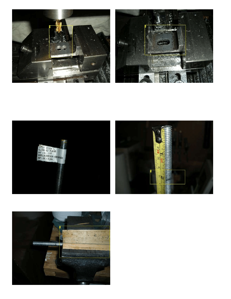
step 10:
Cut the threaded rod
I bought some 3/8"-16 tpi threaded rod from ye olde hardware store. It was cheap and it came with three pies.
I cut it to length with the hacksaw and cleaned up the cut edges with a file.
Image Notes
1. About.... *yay* long.
http://www.instructables.com/id/making_vise_clamps_on_the_milling_machine/
Image Notes
1. I used some wood to protect the threads from the vise jaws.
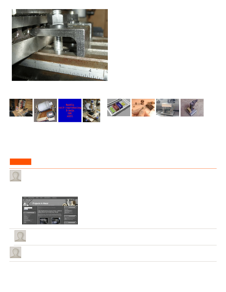
step 11:
Done!
It looks good!
Image Notes
1. Bought these from LMS.
http://www.instructables.com/id/making_vise_clamps_on_the_milling_machine/
Related Instructables
My 30$ Milling
Machine
(slideshow)
by
Ball Mill from
mainly recycled
parts
Mostly self-
reproducing 3-
axis CNC
milling
machine(SHELVED
PROJECT)
by
How to make a
mini milling
machine-
manual or CNC!
make plastic 3D
models from
CAD designs
using an
automated
"milling
machine"
by
by
Heated Stage
for
Thermosonic
Wedge Bonding
Air Engine
(Updated
1/25/09)
(slideshow)
by
Advertisements
Comments
9 comments
says:
Hey, would you mind if I added your project to my site -
?
I'm always looking for fun projects to add to the site and I think my readers would get a kick out of yours. I'm especially short on simple milling projects for the
beginner, so this one would be perfect. You can let me know by clicking on my name here and sending me a private message, or by visiting my site and
filling out the contact form.
Thanks in advance!
says:
Of course, I'd be happy to have this on ProjectsInMetal. I've been checking it out, you've got some cool stuff on there :-)
says:
Daddy like! ima make some tomorrow, i HATE the ones on my Sherline.....stupid bits o metal thanks so much for a simple and nice idea

http://www.instructables.com/id/making_vise_clamps_on_the_milling_machine/
says:
Note: A end mill won't cut a slot exactly to size so you need to use a smaller one and machine each size in turn, just as the Doc has done here. A slot drill
will cut to size and the slot could be cut in one pass.
says:
I like it, but I hate having to tighten the same nuts frequently. I would change those nuts out for lift and set levers but thats another project in itself.
says:
Which came first, the milling machine or the milling machine vise?
says:
The milling machine came first. Its easy enough to mill just by clamping parts to the table, its just a pain to realign everytime you move the piece.
says:
First came the charcoal foundry ;-)
Build your own metal working shop from scrap, by David Gingery
says:
Nice work, Doc!
Wyszukiwarka
Podobne podstrony:
Bearden US Office of Naval Research Report on the Priore Machine
Newell, Shanks On the Role of Recognition in Decision Making
Newell, Shanks On the Role of Recognition in Decision Making
Isabelle Rousset A Behind the Scenes Report on the Making of the Show Visuals and Delivery Systems
#0775 – Making Repairs on the Outside of a House
The Making of a Counter Culture Reflections on the Technocratic Society and Its Youthful Opposition
On the Performance of Minimum Quantity Lubrication in Milling Al 6061
Parzuchowski, Purek ON THE DYNAMIC
Enochian Sermon on the Sacraments
GoTell it on the mountain
Interruption of the blood supply of femoral head an experimental study on the pathogenesis of Legg C
CAN on the AVR
Ogden T A new reading on the origins of object relations (2002)
Hollow Earth Expedition Inside the Drilling Machine
On the Actuarial Gaze From Abu Grahib to 9 11
91 1301 1315 Stahl Eisen Werkstoffblatt (SEW) 220 Supplementary Information on the Most
Pancharatnam A Study on the Computer Aided Acoustic Analysis of an Auditorium (CATT)
więcej podobnych podstron