
1 2
Robot Navigation Schemes
by
Cyliax
Jr.
A
Programmable, Autonomous Robot
by Keith Doty
2 8
A Networking Primer
Part 3: Interconnecting Devices
by Bill Payne
6 2
Standards for Electromagnetic Compliance Testing
Part 3: Immunity and Susceptibility
7 0 •J
From the Bench
You
Can Take It With You
Finding Your Way, Electronically
Bachiochi
7 6
q
Silicon Update
Not Your
MCU
Tom Can
Task Manager
Ken Davidson
For Want of a Nail
Reader
Letters to the Editor
New Product News
edited by Harv Weiner
P
r
i
o
r
i
t
y
I
n
t
e
r
r
u
p
t
Circuit Cellar
Issue
April 1997

BLAST OFF!
Do-While Jones’ series on GPS (“The Global Posi-
tioning System,” INK 77 and 78) came right on time.
I want to launch a rocket, using an M-class motor,
and return it as a glider near its starting point. I’m trying
several devices, including a GPS, in the rocket. I may
buy a GPS unit from Navtech GPS Supply and use the
“GPS 31
(www.navtechgps.com/pcmcia.htm)
and
software. Any advice?
Dan French
If your rocket returns to the launch point, you don’t
need to convert to geodetic coordinates. But, if you
launch your rocket from an
point and want it
to fly to
longitude, that’s another
matter. You can probably work in
geocentric
coordinates.
remember your starting coordinates.
Your autopilot may need to know which way is up,
so just rotate the vector back to the launch point into
an
x-y-up coordinate system and y don’t need to align
with East and North). Since it probably doesn’t matter
if Up is off a couple degrees, don’t worry about Earth’s
curvature over the distance covered by your rocket.
Your rotation matrix probably doesn’t need to be precise.
Do- While
NOT ONLY X MARKS THE SPOT
I read with great interest Do-While Jones’ “The Glo-
bal Positioning System, Part 1: Guiding Stars” (INK
77).
I’ve
worked with GPS for 11 years and am glad to see
INK
cover this technology. While most of the article
was informative and correct, I found some errors.
The article states, receiving -65 signals isn’t
trivial..
That’s true. However, the received GPS sig-
nals are at -160 to -166
They’re below the noise
floor. Check the NAVSTAR GPS Joint Program Office
Web site for verification (www.laafb.
I’d also like to clarify the “Warm-Up Time” section.
Nothing requires warmup. During a cold start (i.e.,
time
with no valid information), the receiver
can require up to 15 min. to provide a position solution.
After this, it should maintain the last known position
via a low-power time source and satellite information
(called almanac and epherimedes) on back-up power.
PCs use the same technique to maintain time and
CMOS set-up data. Provided there’s information from
the last time the receiver was on, the receiver should be
able to reach a position solution in less than 2 min. Dur-
ing this acquisition time, the receiver doesn’t have to be
stationary.
GPS doesn’t need to operate on a car when the igni-
tion is off. The receiver can maintain the required infor-
mation with back-up power, drawing only a milliamp or
two. Since most modern cars draw 30-60
off the
battery when the ignition is off, this isn’t significant. If
the receiver is running, however, the
cur-
rent draw is very substantial compared to the drain from
the rest of the car.
Steven
A MINISERIES, PLEASE
I’m hoping
Cyliax’s “Video
Funda-
mentals” (INK 77) is Part 1 of many. I’d like to see more
detail on implementing an entire system. I’m putting
together a functioning system and need more details.
Keep up the good work. Every issue of INK stretches
the old “squishyware.”
David Bley
Contacting Circuit Cellar
We at Circuit
Cellar
communication between
our readers and our staff,
so we have made
effort to make
contacting us easy. We prefer electronic communications, but
feel free to use any of the following:
Mail: Letters to the Editor may be sent to: Editor, Circuit Cellar INK,
4 Park St., Vernon, CT 06066.
Phone: Direct all subscription inquiries to (800)
Contact our editorial off ices at (860) 875-2199.
Fax: All faxes may be sent to (860)
BBS: All of our editors and regular authors frequent the Circuit
Cellar BBS and are available to answer questions. Call
(860) 871-l 988 with your modem (300-l
bps,
Internet: Letters to the editor may be sent to
corn. Send new subscription orders, renewals, and ad-
dress changes to
Be sure to
include your complete mailing address and return E-mail
address in all correspondence. Author E-mail addresses
(when available) may be found at the end of each article.
For more information, send E-mail to
WWW: Point your browser to
6
Issue
April 1997
Circuit Cellar
Edited by Harv Weiner
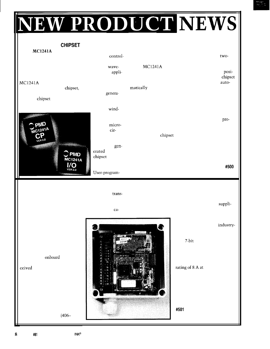
MOTION-CONTROL
The
is a dedicated motion processor that
mable registers enable the amplitude and frequency of
functions as a complete chip-based stepper-motor
these waveforms to be precisely controlled. Both
ler. Its drive method lets each phase of a stepper motor
and three-phase stepper motors are supported.
be individually controlled with a microstepping
The
also provides inputs for quadrature
form. This configuration is ideal for stepper-based
encoder feedback. Each axis maintains the encoder
cations that require smooth, high-accuracy motion. The
tion to a 32-bit resolution. A special feature of the
is available in one- or two-axis configurations.
is that if an encoder is connected to the motor, it
Packaged in a two-IC
this device performs
detects a motor-stall condition during motion.
trajectory generation and microstepping signal
If an encoder is not connected to the motor, it drives the
tion. The
outputs PWM- or DAC-compatible
motor using a traditional open-loop approach.
motor command signals that directly drive the stepper
Other standard features include four user-selectable
motor’s
profiling modes, as well as S-curve, trapezoidal, velocity
ings, eliminating
contouring, and electronic gearing. All profile control
the need for
registers are 32 bits. Additional control modes are
external
vided for automatic position breakpoints, host interrupt
stepping
generation, and multiaxis synchronization.
cuitry. The
The two-axis
sells for $65 in quantity.
microstepping
waveforms
Performance Motion Devices, Inc.
by the
97
Lowell Rd.
provide
Concord, MA 01742
64 microsteps
(508) 369-3302
per full step.
Fax: (508) 369-3819
PAGING DATA RECEIVER
The PDR-100 enables industry-standard paging
missions to operate remote relays and deliver ASCII
RS-232 messages to a remote site. Applications include
electric utility load control, customer notification,
pacitor bank switching, traffic
control, remote HVAC control,
lighting, and signs.
The unit can receive numeric
and alphanumeric pages. The
string of digits received in a
numeric page is decoded and
interpreted as commands to
operate three
relays.
The ASCII-character string re-
in an alphanumeric page
is output through an RS-232
serial port, which can drive a
printer or other RS-232 device.
The PDR-100 uses Motorola’s
Bravo Plus receiver technology
to
receive and decode broadcasts
over an existing paging infra-
structure. It is available for VHF
(138-174 MHZ), UHF
5 12 MHz), and 900-MHz (929-932 MHz) frequencies.
The PDR-100 operates with existing paging systems or
with one of the many third-party paging-service
ers. The unit’s design enables a single paging account to
address units for relay control
either individually or as a group.
The paging interface is
standard POCSAG 512, 1200, or
2400 (numeric and alphanumeric
with
ASCII).
The PDR-100 is housed in a
5.12” x 5.12” x 3” weatherproof
enclosure with a tamper-seal
cover. Its relays have a contact
115VAC.
Technicom, Inc.
20 Washington Ln. SE
Concord, NC 28025
(704) 788-8944
Fax: (704) 782-l 122
Issue
April
1997
Circuit Cellar
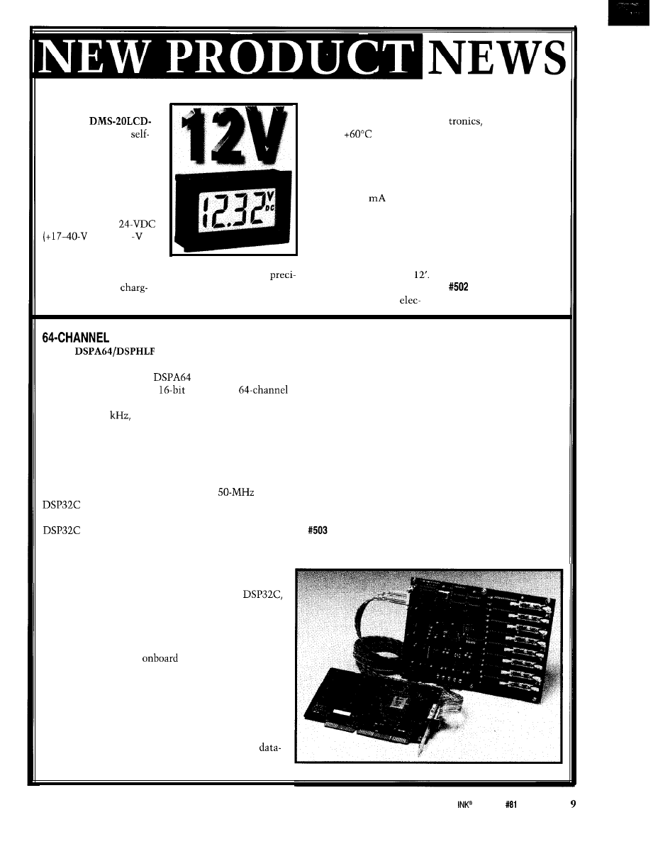
DC VOLTAGE MONITOR
is housed in an
ABS plastic package mea-
suring 1.38” x 0.88” x
0.66”.
Pricing starts at $25 in
single quantities.
Datel’s
excellent performance over
DCM
is a low-cost,
the 0 to
operating
contained, self-powered,
temperature range. Applying
DC voltage monitor. Two
power to the two rear termi-
models are available-one
nals is all that’s required for
for 12-VDC nominal
operation, and the unit
operation (+6.5-18-V
draws only 2
from the
range, 0.01-V resolution),
monitored source. Reverse
and the other for
polarity protection is stan-
range, 0.1
dard on both models. The
resolution). Applications
0.37” high LCD display with
include DC bus-voltage
built-in VDC annunciator
monitoring, automotive
The monitor uses a
can easily be read from
batteries, battery
sion ADC and ultra-stable
The entire unit, including
ers, and solar generators.
passive components to gain
its display and SMT
Datel, Inc.
11 Cabot Blvd.
Mansfield, MA 02048
(508) 339-3000
Fax: (508) 339-6356
A/D SYSTEM
The
system from Symmetric Re-
search is a complete, PC-based system for A/D acquisi-
tion and processing. The
card is external and
features a high-resolution
ADC and a
programmable multiplexer array. Sampling at aggregate
rates up to 138
all inputs are differential and buff-
ered through a low-noise precision instrumentation am-
plifier. In addition, overall gain and amplitude limits can
be user set by resistors, with nominal values of 1 .O and
f2.75 V. A 16-conductor ribbon cable transfers the data
in serial form to the DSPHLF card inside the PC.
The DSPHLF card, which features a
AT&T
floating-point DSP, processes and buffers up to
1 MB of incoming data without using any PC time. The
double buffering enables large blocks of data to
continuously be saved to the hard disk with no data loss.
Because the PC is completing only disk saves, PC
time is available for displaying graphics or running a
windowed environment.
Incoming data is processed up front by the
so you can apply digital filters to the incoming data in
real time. Data can be oversampled then smoothed to
increase the system’s overall effective resolution. This
powerful feature is further enhanced because DSPHLF
programs are saved in
SRAM and can be
changed anytime by the user. This capability enables
you to modify filtering coefficients and other param-
eters as necessary in real time.
The system offers a complete development envi-
ronment which provides all the tools necessary to
develop custom code and applications, including an
assembler and monitor debugger. A full-featured
acquisition kernel and display program lets users
specify selected channels, control acquisition rates, con-
tinuously save data, and optionally run a real-time dis-
play. Full source code for the acquisition program, as
well as many introductory example programs, is in-
cluded. Full circuit diagrams offer hardware specifics.
The complete package, including software and power
supply, is priced at $2500.
Symmetric Research
15 Central Way, Ste. 9
Kirkland, WA 98033
(206) 828-6560
Fax: (206) 827-3721
Circuit Cellar
Issue
April 1997
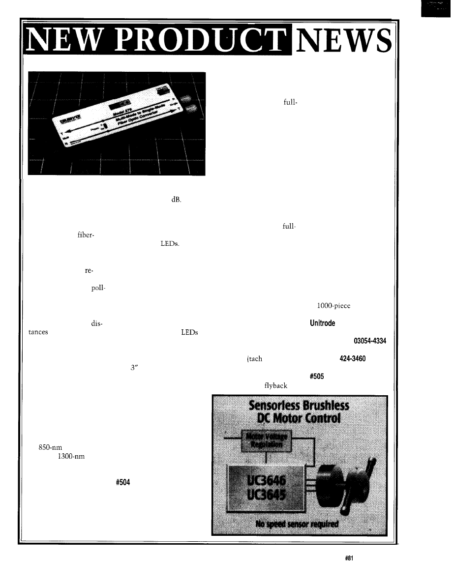
FIBER-OPTIC CONVERTER
The Model 279 single-
of 2, 5, 10, and
15
These
mode-to-multimode
losses approximate cable
fiber-optic converter
lengths of 3, 7.5,
15,
and
provides long-distance
20 km, respectively. The
transmission of
selected line loss is displayed
optic signals. A unique
on one of four
feature enables its use in
When used as a media
systems that have nulls
converter, the phase of the
in their frequency
fiber-optic signals may not
sponse, as is often the
be the same. The Model 279
case in master/slave
includes a phase-reversing
ing networks. Typically,
switch for situations where
multimode transmission
the signal phases of the
services distances of
single-mode and multimode
-2 km. For extended
are different. In addition,
(i.e., up to 20 km),
transmit and receive
single-mode fiber is used.
display the activity of data
For applications where
passing through the unit.
multimode equipment is
The Model 279 measures
used but only single-
7” x x
1”
and can mount
mode fiber exists, a pair
in any position. Power is
of Model 279s performs
supplied by a wall-mounted
the media translation
adapter. The Model 279
from multimode to
sells for $775.
single-mode, enabling the
use of single-mode fiber.
Telebyte Technology, Inc.
The Model 279 offers
270 Pulaski Rd.
full-duplex conversion
Greenlawn, NY 11740-l 616
for
multimode
(516)
423-3232
signals to
single-
Fax: (516) 385-8184
mode signals. All fiber
telebyteusa.com
ports are implemented
with ST connectors. A
line-loss switch compen-
sates for single-mode
cable loss, allowing the
unit to accommodate
single-mode cable losses
DCMOTORCONTROLLER
The UC3645 and UC3646
are bipolar integrated cir-
cuits designed to drive
wave brushless DC motors
without position sensors.
Bidirectional control in-
creases design flexibility,
while sensorless commuta-
tion reduces component
counts and cost. The devices
are ideal for micro motor
control under 24 W (e.g.,
copiers, laser printers, fax
machines, hard disks, and
tape drives).
The UC3645 and UC3646
are designed for use in
wave drive of three-phase
motors. Two 1.8-A drivers
are active at one time in
each of the six output states.
As one sources current, the
other sinks it. The internal
logic determines the ideal
time to commutate the
motor based on the EMF
signal evaluation of all out-
puts generating a motor
position signal. The same
signal also provides speed
information via the FG
output pin
output].
Because the motor load is
highly inductive, the out-
puts incorporate
diodes. Current limiting
and thermal protection
are provided, as well as
soft start and program-
mable commutation
delay. Internal start-up
and timing oscillators
create a minimum com-
mutation frequency and
detect reverse rotation
since EMF signal is not
available during startup.
The UC3645 has a
transconductance ampli-
fier for driving a linear
regulation transistor for
low-noise motor voltage
control. The UC3646
uses a PWM comparator
to drive a switching regu-
lator transistor for highly
efficient motor voltage
control.
The UC3645 and
UC3646 are priced at $4.94
in
quantities.
Corp.
7 Continental Blvd.
Merrimack, NH
(603) 424-2410
Fax: (603)
Circuit Cellar INK@
Issue
April 1997
11
FEATURES
Robot Navigation
Schemes
Talrik, Jr.
A Networking Primer
Robot
Navigation
Schemes
Cyliax
0
or mobile robots
to be useful, they
have to know where
they are.
In this article, I describe several
useful techniques for navigating mobile
robots, including dead-reckoning and
beacon-based systems. The challenge
in robotics, as with all engineering, is
to arrive at an optimal cost-effective
solution that does the job. But that’s
difficult, especially with navigation.
At first, the solution might seem to
be slapping a GPS receiver on the ro-
bot. However, if you’re dealing with
small inexpensive robots like Stiquitos
or Servobots (see “Modular Robot
Controllers” in
it’s not quite
that easy.
To illustrate my ideas, I show you a
small navigation system based on
components available from mail-order
sources. The system uses a neat way to
compute accurate trig functions, which
is described in detail in the
about CORDIC. You can integrate this
system into your next mobile-robot
project.
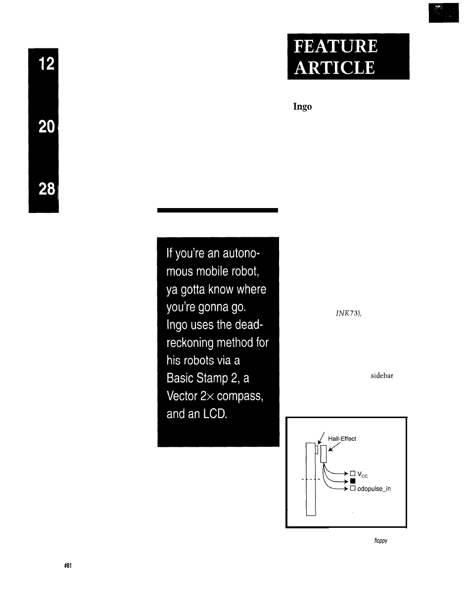
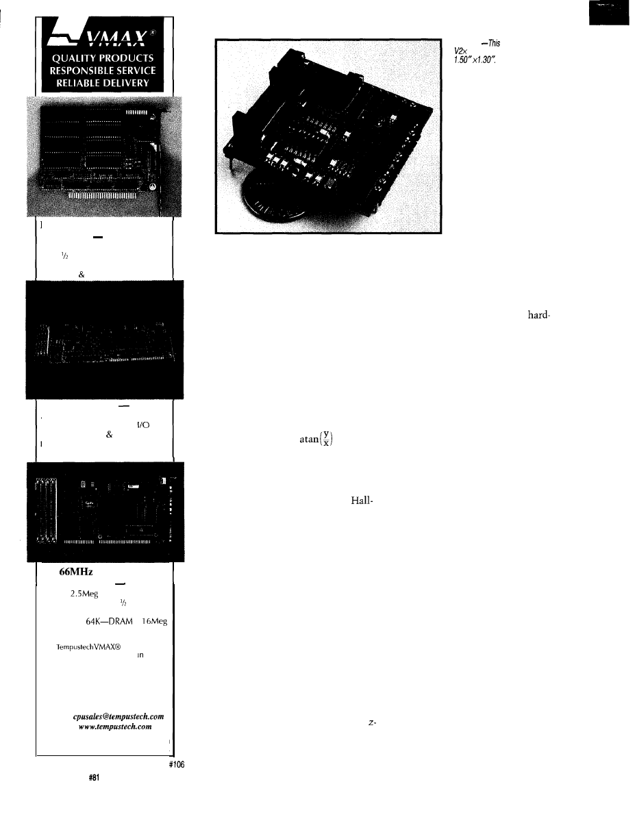
Little Magnet
Sensor
Gnd
Wheel
Figure l-/n this
simple odometer for a wheeled robot,
the magnet and sensor come from a 3.5”
disk
drive.
12
Issue
April 1997
Circuit Cellar INK@
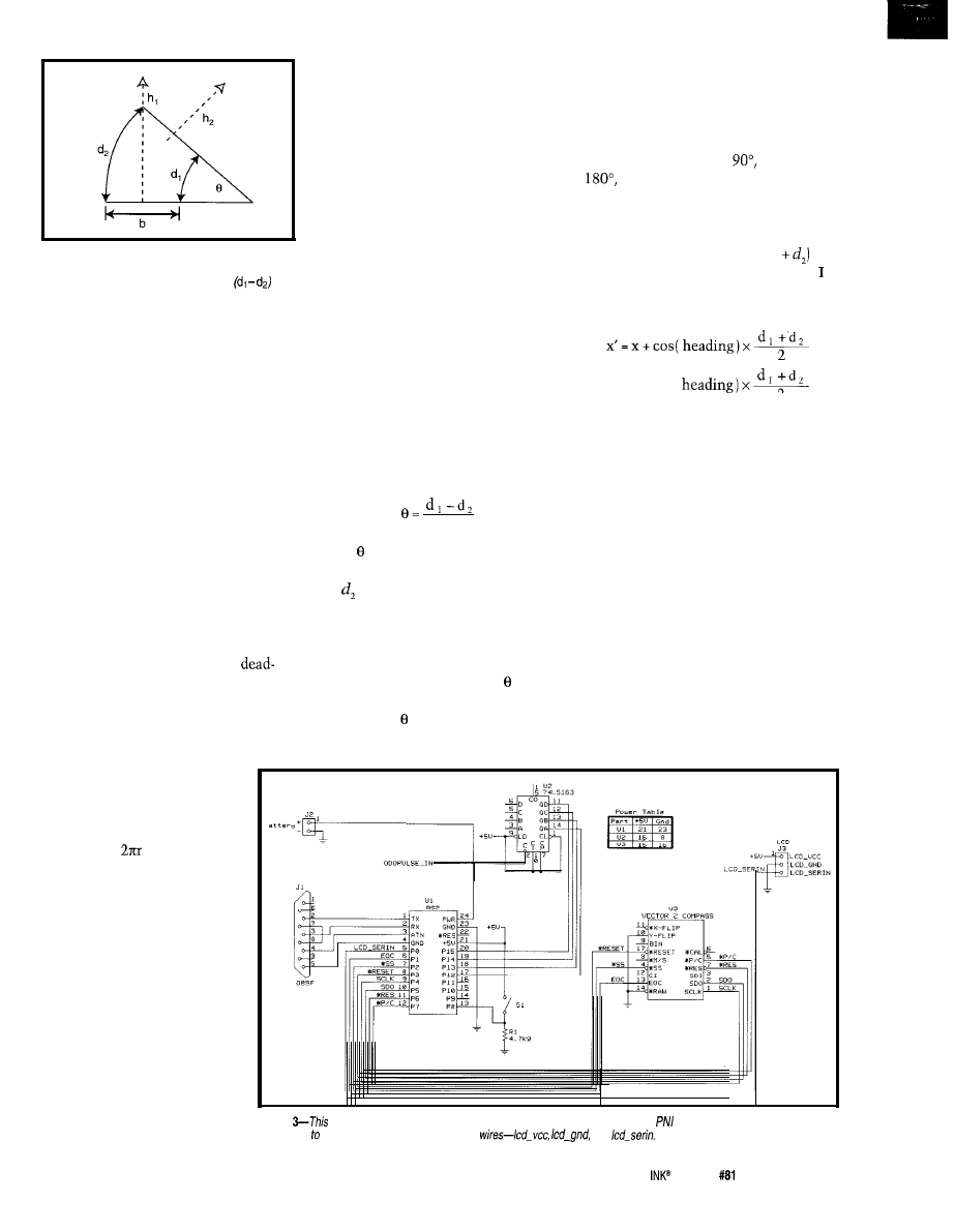
Figure 2-For this differential drive heading sensor,
both wheels have an odometer with enough resolution
to send fhe difference in distance traveled by
each wheel in a curve.
Now, how do I find the current
heading? Let’s look at some techniques
that can be easily implemented on a
robot.
DEAD-RECKONING
Dead-reckoning is probably the
oldest navigation system there is. In
dead-reckoning, you track your current
position by noting how far you’ve
traveled on a specific heading.
One way to find the heading is to
use one odometer per wheel, assuming
there are two or more. Remember to
note the difference in distance traveled
by each wheel since, when the robot
turns, one wheel travels a farther than
the other.
I now have a vector which is the
average distance of half of (d,
at a
certain angle. To track the position,
accumulate the x and y components of
this vector:
y’=y+sin(
2
For centuries, sailors used a mag-
netic compass to note their heading
and a combination of sand/water clocks
and knotted ropes to measure time and
speed. Of course, with ocean currents,
this method was never that accurate.
Look at Figure 2 to see this effect.
To calculate a change in heading from
this, use simple trigonometry:
b
Besides the differential wheel-head-
ing indicator, an electronic compass
directly measures absolute heading.
The earth’s magnetic field is about
0.5 G and can be visualized by imagin-
ing a huge magnetic dipole with poles
roughly at the north and south poles.
Ships often missed their destination
or never made it home. Perhaps that’s
why it’s called dead-reckoning. With
the invention of the sextant and chro-
nograph, things got much better-but
more about that later.
where is the angle in radians, b is the
distance between the wheels, and d,
and are the distances traveled by the
right and left wheels, respectively.
To track the absolute heading,
accumulate the change in each turn:
They aren’t really at the poles, and
the deviation is called the declination.
This fact is important when using
compasses for global navigation, but
not for local navigation.
In robotics, we can also use
reckoning. Measuring distance is easy
with wheeled robots and some kind of
odometer. By putting an encoder on a
wheel and measuring the number of
revolutions, it’s simple to
calculate the distance traveled
if you know how big the wheel
is:
heading’ = heading +
Note, that goes negative when the
left wheel travels a greater distance
Three kinds of electronic compasses
are available-actually, one isn’t elec-
tronic in the strictest sense. An elec-
tronic compass uses a magnetometer
to measure the earth’s field, while
another compass commonly referred to
distance =
x revolutions
Figure
1
shows a simple
odometer that provides a
pulse each time the wheel
completes a rotation. The
Hall-effect sensor comes from
a floppy disk drive.
By mounting more mag-
nets, I can increase resolution
by increasing the number of
pulses per revolution. For
example, eight magnets let
me measure distance down to
one-eighth of the circumfer-
ence, simply by counting
Figure
dead-reckoning navigation system uses a Parallax Basic Stamp 2 and a
electronic compass module. The
connection the serial LCD module is via three
and
pulses. The more pulses, the better the
resolution.
With a position encoder, I can mea-
sure the absolute position of the wheel
and, more importantly, the direction of
travel. If I use stepper motors or legs,
measuring the distance is a breeze.
I
just count the steps and multiply by
the distance traveled with each step.
than the right wheel. Also, the abso-
lute heading is positive in a counter-
clockwise direction. This contrasts
with a compass heading, which is
positive in the clockwise direction
(i.e., north = 0”, east =
south =
and west = 270”). Therefore, the
new absolute heading after the turn in
Figure 2 is smaller than it was before.
Circuit Cellar
Issue
April 1997
1 3
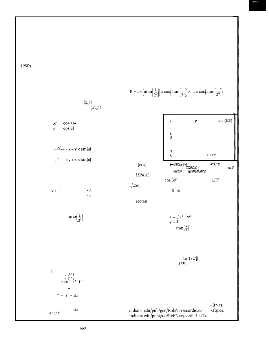
CORDIC-The Swiss Army Knife for Computing Math Functions
CORDIC [Coordinate Rotation Digital Computer) is a
method for computing elementary functions using mini-
mal hardware (e.g., shift and add). It’s typically used
when functions need to be implemented directly in hard.
ware.
Initially, CORDIC was hardware developed for real-
time high-precision navigational computations in the
Since then, this technique has been integrated
into almost all scientific calculators.
CORDIC works by rotating the coordinate system
through constant angles until the angle reduces to zero.
The angle offsets are selected so that the operations on x
and y are only shifts and adds. Let’s first look at the math
and then an example.
1’11 start with some coordinates
which I want to
rotate by angle a. The new coordinates
are defined
by:
= x
y sin(a)
= y
+ x sin(a)
I
rewrite these to get a tangent of the angle:
cos
(a)
Y’
cos [a)
If I break the angle into smaller and smaller pieces so
the tangents of these pieces are always powers of 2 and
they still add up to the total angle, I can write:
= K(i) x (x(i)
y(i+l) = K(i) x (y(i) +
where the angle for each step is:
A(i) =
I
won’t worry about the K(i) for now because there’s
an easy way to deal with it. With these iterative equa-
tions, I can design an algorithm that, given an angle in a,
will reduce this angle to zero.
At each step, it also increments or decrements the x
and y coordinate register by the appropriate value (i.e.,
shifted values of x and y), thus keeping track of the coor-
dinates while rotating:
for = 0 to N
dx = X
dy = Y
da =
if Z >= 0 then
X=X dy
A = A - d a
else
X = X + d y
A = A + d a
Y = Y
next
In a real program, I’d precalculate the atan( I/2’) values
and store them in a lookup table. The divide by 2’ should
end up as a simple shift instruction on most architec-
tures.
So, how do I calculate the sine and cosine with this? I
use this algorithm with initial values and let it calculate
the answer. For example, I initialize the angle as 30” and
iterate by 8 steps (equivalent to 8 bits of precision).
Remember the K(i) constants and how they were miss-
ing in the last algorithm? By multiplying all the K(i)s
together, I get what’s called the aggregate constant:
which turns out to be 0.607. It’s the same constant re-
gardless of the precision. You can just truncate it to the
number of bits
you need. I use
it to initialize
X
a
the x register
0
0.607
0.000
30.000 45.000
and turn the
1
0.607
0.607 -15.000 26.565
crank, as you
0.835 0.910
0.303 0.531
-2.471 11.565 14.036 7.125
can see in Table
4
0.901
0.427
4.654
3.576
5
0.874 0.483
1.077
1.790
i.
6 0.859 0.510
-0.712 0.895
The answers
0.867 0.497
0.183 0.448
0.863 0.504
0.224
appear in regis-
ter x
and y
Table
the sine and cosine
8 bits
(sin). My trusty
of accuracy using
fakes eight steps. The
is in the
and
in step 8.
old
got
sin(30) = 0.500 and
= 0.866. Of course,
is
which ends up being 0.0039. So, I can’t really hope
for more accuracy with
precision.
CORDIC can do much more. You can also calculate
the
by initializing the x and y registers, setting a
to zero and driving y to zero, with the results:
a =
Having the vector magnitude of x and y in x can be
handy, don’t you think?
Some clever people also figured out a way to use
CORDIC to calculate other functions such as exponen-
tial functions (using a table of
and hyperbolic
trig functions (using atanh[
tables).
Check out the references for this article for applica-
tions and refinements of this technique.
If you need high-precision trig functions with a small
look-up table (n entries) and good performance, give
CORDIC a try. I can even implement a 12-bit CORDIC
routine on a Parallax BASIC Stamp 2.
You can get the C code used to calculate Table i and
an example of the Stamp II CORDIC code at
and
14
Issue #El April 1997
Circuit Cellar
ENHANCED SOLID STATE
DRIVE
$105"
4M Total, Either Drive Bootable
Card 2 Disk Emulator
Flash System Software Included
FLASH SRAM, Customs too
486 SLAVE PC $898”
Add up to 4 Boards to One Host PC
Fast Data Transfer and
PC-1 04 Port, IDE Floppy Control
ndependent Processors on One Bus
No Special Compilers Needed
486
SINGLE CARD
COMPUTER $335”
Up to
Flash&ram drive
Compact-XT height card size
Industry Standard PC-1 04 port
L2 cache to
to
Dual IDE/Floppy connectors
All
products are
PC Bus Compatible. Made the
U.S.A., 30 Day Money Back Guarantee
*Qty 1, Qty breaks start at 5 pieces.
TEMPUSTECH, INC.
TEL: (800) 634-0701
FAX: (941) 643-4981
E-Mail:
I-Net:
Fax for
Fast response!
295 Airport Road
Naples, FL 34104
as electronic is just a magnetic com-
pass with a position encoder detecting
which direction the needle points.
Such compasses are a bit bulky for
robotics, but they’re simple.
The most common electronic com-
pass is the flux-gate compass. It uses a
flux-gate-based magnetometer to mea-
sure the magnetic flux of the earth
directly. Two sensors measure the x
and y components of the field at the
current heading.
To calculate the heading, take the
arctangent of the ratio:
heading=
which is really neat, since the actual
magnitudes of the fields cancel out in
the fraction.
A Hall-effect compass uses a
effect transistor instead of flux-gate
sensors, and it’s simpler, smaller, and
more robust than a flux-gate compass.
It’s completely solid state and doesn’t
require coils. Like all good things in
life, Hall-effect-based compasses are
more expensive.
The earth’s magnetic field isn’t
parallel to the earth’s surface except at
the equator. For a compass to work
properly, it must be aligned parallel to
the earth’s surface to measure the x and
y components of the field accurately.
Alignment is achieved by using a
gimbal mount or by putting the com-
pass in a bubble of oil so gravity levels
the compass and the oil dampens vibra-
tions. Some compasses have a third
axis sensor to measure the field when
mounted in any position.
Photo 1
Precision
Navigation
compass module measures
You
can a/so see the
two sensor coils.
Another complication
are magnetic fields intro-
duced by EM emissions.
Since these emissions
are normally generated
by AC, they can be fil-
tered out electronically
or by the viscous damp-
ening used in physical
compasses. This explains
why compasses usually have a low
sampling rate (i.e.,
5-10 Hz).
If the vehicle with the compass
includes any ferroelectric materials
that alter magnetic flux lines, you
need to compensate by doing a
iron calibration. Calibration is also
necessary on robots that may include
the static magnetic fields typically
found in permanent magnet motors.
Environmental (nonvehicular) mag-
netic fields may also need to be com-
pensated for. Since they are static, a
map-based look-up table can be used.
Inertial navigation systems, which
are based on gyroscopes, don’t suit
robotics applications. Small units tend
to drift too much, and low-drift units
are too expensive and bulky.
Rate gyros augment other naviga-
tional systems to provide some rota-
tional stability with a faster response
time than a compass. Small and light
rate gyros compensate for the torque
present in radio-controlled model heli-
copters.
DEAD-RECKONING PROJECT
You
can build a simple dead-reck-
oning system with readily available
components. My system consists of a
Parallax Basic Stamp 2 and a Vector 2x
electronic compass made by Precision
Navigation Inc. (shown in Photo
1).
Both the Stamp and the compass are
also available from Jameco and JDR.
Figure 3 shows the setup.
Odometer pulses are buffered using
a counter (‘163) to ensure that nothing
is missed. Interfacing the compass
module is straightforward by using a
16
Issue
April 1997
Circuit Cellar INK@
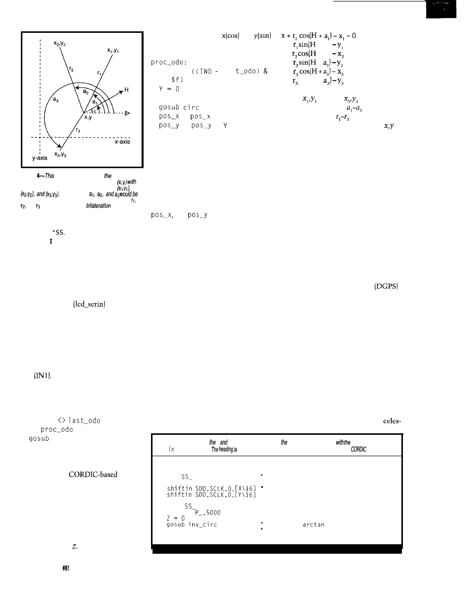
Figure
vector diagram shows relationships
between the vehicle at an unknown location
a
heading of(H) and three known beacons at
The angles
measured in a triangulation system. The distances
and would be known in a
system.
synchronous serial protocol with SCLK,
SDO, and
When want to take a reading, I
pulse the *P/C (poll) line and wait until
the conversion is done, which is sig-
naled by the EOC line. The data is
now valid and can be read serially.
Finally, a serial LCD module records
the position and current heading. A
single serial line
interfaces
with the LCD module.
On the software side, things aren’t
quite so simple, but they’re still man-
ageable. The main loop continually
polls the odometer by reading the high
nibble of the 16-bit input register (IND)
and the state of the compass’s EOC
line
It then dispatches to the
appropriate routine for processing:
main:
if
IN1 = 1
then proc_compass
if
IND
then
display
got0 main
To process the current odometer
reading, I use a
routine
to compute the sin and cos components
of the current vector (heading and
distance) and add them to the current
position.
The CORDIC routine scales the
distance by the aggregate constant in
register x and the angle (i.e., the cur-
rent heading) in The scaled vector
18
Issue
April 1997
Circuit Cellar INK@
components will be in
and
and are added to the current position:
X = K *
las
y +
+ a,) = 0
x +
+ a,) = 0
y +
+ = 0
x +
= 0
y + sin(H + = 0
Z =
heading
where
through
are known
locations of beacons,
are relative
=
+ x
angle to beacons,
are the distance
=
+
to beacons,
His
the heading, and
is
got0 main
my location.
To process the compass, read the x
and y field measurements and calculate
the heading by taking the arctangent
and storing the result in the variable
he ad
i n g,
as you see in Listing 1. The
subroutine d
i s
pl ay formats and dis-
plays the current values for he ad i n g,
and
on the LCD.
The only other thing to note about
dead-reckoning is that systematic er-
rors (i.e., resolution in the encoder and
uncertainty of the exact heading) accu-
mulate. To overcome this, a typical
dead-reckoning system needs calibrat-
ing occasionally by aligning the cur-
rent position with an actual position.
BEACON-BASED NAVIGATION
Beacons are locations with known
coordinates which emit signals (e.g.,
radio waves or light) to be received by
the vehicle trying to find its location.
Measuring the distance to these bea-
cons is called trilateration. Other types
of systems measure the angle to the
beacon, in which case it’s called trian-
gulation.
Generally, we end up solving for x
and y (and maybe H, the heading) in
the following system of equations,
which go with Figure 4:
Today, the most common naviga-
tional systems-GPS, Loran, Omega,
and VOR-use trilateration by measur-
ing the time of flight (TOF) or phase
relationships of radio signals from the
beacon to the vehicle. Even though
these systems really use TOF and
carrier-phase relationships and are
trilateration systems, they often pro-
vide heading information to a user.
While these systems work well for
finding airports and harbors, it’s fairly
hard to measure distances with fine
resolution. Radio waves propagate in
the order of 1’ per nanosecond, which
calls for very accurate clocks.
Of course, differential GPS
can accurately obtain position even
with selective availability turned on,
but the equipment is too expensive for
low-end robotics. It also requires a
second stationary GPS receiver to
communicate with the robot.
Most of the low-cost trilateration
systems for robotics rely on ultrasonic
beacons. Sound waves travel at a rate
of -900 per second, giving plenty of
time for TOF measurements. Laser
range-finding can measure the distance
to laser targets.
Examples of real-life triangulation
systems include lighthouses and
Listing l--Reading x
y magnitudes from compass module is done
Stamp 2’s
shift instruction.
calculated by taking the arctangent using the
technique.
proc_compass:
pause 10
low
pause 10
high SCLK
high
pulsout
heading = Z
got0 main
assert select
read sensor values
calculate
the answer

tial navigation, which is still used as a
back-up system to man-made
based systems. For celestial navigation,
a sextant measures the inclination of
celestial objects above the horizon as
well as a chronograph (a very accurate
clock) for transit measurements.
Luckily, most triangulation systems
available to the robot designer are based
on lasers which scan for targets (e.g.,
ID tags or retroreflectors). Some hybrid
systems give range information in
addition to angles.
SENSOR FUSION
You
now know about several navi-
gation schemes. Most have strengths
and weaknesses. In navigation, we’re
mostly worried about accuracy and
having backups.
Imagine a ship that relies on GPS,
but the GPS receiver dies. After all, it’s
a fairly complex system and relies on
data (the ephemeris) downloaded from
the satellite.
A backup for this might be the
Omega navigation system, which is a
VLF (very low frequency] radio naviga-
tion system using phase-carrier com-
parisons to give vectors. This system
isn’t available everywhere in the world,
and even where it is available, it has
variable accuracy depending on your
location and how many transmitters
you can receive.
You could also fall back on
reckoning. Ships keep logs about how
fast and long they’ve traveled on a
particular heading. A sextant and chro-
nograph can be used to get a fix on the
current location to update the estimate
that dead-reckoning gives.
In nautical navigation, several sys-
tems are used. Each system has an
accuracy that enables the navigator to
assign a certainty of how reliable the
information is. Systems with higher
accuracy are used when available.
In robotics, we do this with sensor
fusion. We can estimate our current
location by assigning weights to each
measurement which implies a certain
“correctness” value. We then average
GPS satellites are in view, how
date the element data is, and perhaps
While GPS is operating, it has a
what the distance is to each satellite.
much higher weight than an odometer,
which suffers from systematic errors,
and an electronic compass, which has
low accuracy compared to GPS. How-
ever, when no GPS satellites are avail-
able, the weight for the dead-reckoning
sensors is higher and thus more correct.
WHERE TO GO FROM HERE
While there’s a lot of information on
this topic, it merely indicates that this
problem is not so easy to solve.
At the University of Indiana, we
haven’t found a cost-effective solution
for doing navigation in our colony
robots besides using a video camera to
find blinking
However, the
small size of the compass used in my
project looks attractive for our bigger
walking robots, especially since we
can measure distance fairly accurately.
A good reference on robot naviga-
tion systems is Johann Borenstein’s
report put out by the University of
Michigan. It describes and compares
almost all commercially available and
research-based navigation systems and
schemes that can be used by robots.
q
Cyliax works as a research engi-
neer in the Analog VLSI and Robotics
Lab and teaches hardware design in
the computer science department at
Indiana University. He also does
ware and hardware development with
Derivation Systems, a San Diego based
formal synthesis company. You may
reach
at
C.
Robot Builder’s Bonanza,
J.E. Volder, “The CORDIC Trigono-
TAB Books, Blue Ridge Summit,
metric Computing Technique,” IRE
PA, 1987.
Trans. Electronic Computing, 8,
330334, 1959.
Web sites:
www.taygeta.com/cordic_refs.html
html
compass module
Precision Navigation, Inc.
1235 Pear Ave., Ste. 111
Mountain View, CA 94043
(415) 962-8777
Fax: (415) 962-8776
www.pcweb.com/pni
Basic Stamp 2
Parallax, Inc.
3805 Atherton Rd., Ste. 102
Rocklin CA 95765
(916) 624-8333
Fax: (916)
info@parallaxinc.com
www.parallaxinc.com
Serial LCD Module
Scott Edwards Electronics
P.O. Box 160
Sierra Vista, AZ 85636
(520)
Fax: (520) 459-0623
Compass, Basic Stamp, LCD module
JDR Microdevices
1850 S. 10th St.
San Jose, CA 95 112
(408)
All software mentioned in this
article is available at
Fax: (408) 494-1420
www.jdr.com
Jameco
1355
Rd.
Belmont, CA 94002
(415)
Fax: (415) 592-2503
info@jameco.com
Texts:
www.jameco.com
reliable this guess might be.
If I used GPS, for example, I’d assign
a
correctness factor based on how many
A. K. Peters, Ltd., Wellesley,
MA, 1996, and
401
Very Useful
402 Moderately Useful
403 Not Useful
Circuit Cellar INK@
Issue
April 1997
19

Talrik, Jr.
A Mobile
Programmable,
Autonomous
Robot
port and a programming language.
Freeware compilers, simulators, and
assemblers for low-cost microcontrol-
lers reduce entry prices considerably.
However, for long-term reliable sup-
port, the robot developer must eventu-
ally turn to commercial software.
In this article, I introduce you to a
low-cost
open-architec-
ture, autonomous mobile robot. is
my hope that widespread use of such
robots will generate small industries in
worldwide have taken a realistic
sensors and application packages that
to the design and development
will operate on a real, simple, easy to
of autonomous mobile robots. The
build and use,
increasing expectation and demand for
robot platform.
robotic
to autonomouslv
form complex tasks in manufacturing,
construction, transportation, and con-
sumer services are driving this research.
Applications for autonomous mo-
bile robots include diverse products
like lawn mowers, vacuum cleaners,
industrial and nuclear cleanup, mili-
tary warriors, scouts, and saboteurs, as
well as construction, underwater
search, and transportation vehicles.
Some companies offer small mobile
robots priced from $1000 to more than
$20,000. A few start-up firms offer
robots for $500 to $1000, with perfor-
mance characteristics competitive
with some of the more expensive mod-
els. The lower-cost models carry much
smaller payloads, but their size is
1000 times smaller as well.
The complexity and high cost of
current robot platforms prevent many
from exploring and applying machine
intelligence, neuronets, reinforced
learning, and fuzzy logic to robots.
Advances will be rapid, however, when
the industry devises an inexpensive
but sufficiently complex robot that
supports behavior programming, learn-
ing, and manipulation capability.
START-UP COSTS
Even a minimum functioning auto-
nomous mobile robot requires multiple
sensors of various types, one or more
microcontrollers, a power source,
MEET TALRIK, JR.
The design of Talrik, Jr. (alias “TJ”)
derives much from its parent-Talrik 1,
a much larger robot with more capabil-
ity and higher cost.
As you can see in Photo 1, TJ stands
about 4” high, with an upper circular
plate 6.5” in diameter. The platform
consists of
aircraft birch ply-
wood, but other light, strong materials
are easily substituted.
A minimal TJ sensor suite consists
of two IR emitters with two IR detec-
tors and three front bumper switches.
Two 2.75” rubber-tire model-airplane
wheels and a rear nylon skid provide
support.
The wheels mount directly on stan-
dard model-airplane servos’ output
shafts. The axis aligns with the upper
plate’s diameter so TJ can turn in place
by differential control of the motors.
A built-in recharge circuit and power
plug offers a 6-h trickle charge by an
AC adapter of
12
VDC and 200
TJ
can recharge during long hours of test-
ing and debugging, keeping batteries
fresh and ready to go for floor testing.
Of course,
wheels must be elevated
above the bench top during this time!
A Motorola
proces-
sor on a 2” x 2” PCB controls
DC
motors and sensors and executes be-
havior programs. The ‘E2 provides 256
bytes of RAM and 2 KB of EEPROM,
20
Issue
April 1997
Circuit Cellar INK@
which is sufficient space to implement
a variety of sophisticated behaviors.
Motor-control software generates
pulse width modulation for the two
DC motors on PB7 and PB6 of port B
(see Figure 1). The DC motors are
standard 42 oz.-in. servos modified to
always feedback the servo center posi-
tion to the servo control circuitry.
Any pulse-width command between
l-2 ms on the port-B output pins indi-
cates a set point that the servo can’t
achieve unless it’s the center position.
This position corresponds to a control
pulse width setting of -1.5 ms. A set
point greater than 1.5 ms causes the
motors to turn forward. A setting below
that causes the motor to reverse.
The PWM period varies
18-20 ms.
Differential control of the motors
provides complete maneuverability. TJ
can turn 180” in place.
The
provides eight
channels of
ADC [port E) for
sensory inputs. Port B furnishes eight
digital outputs, and port C can be pro-
grammed for either inputs or outputs.
TJ has two forward- and one back-
ward-looking IR emitter to illuminate
the scene with
modulated,
940-nm IR. PBO drives all three emit-
ters in 2.5ms bursts (see the series
LED circuit in Figure 1).
Two forward-looking,
Sharp
digital IR detectors complete
the IR proximity-detection system.
This system handles obstacle
wall following, and beacon detec-
tion
The two front IR-detector outputs
feed into analog inputs PE6 and PE7.
An optional rear IR detector driving
analog input PE2 enables TJ to detect
IR from other
(or predators!).
Adding a bump sensor on the upper
plate provides collision detection.
SINGLE-CHIP COMPUTER CIRCUIT
When a project doesn’t demand
extensive computer capability or mem-
ory, a small, compact microcontroller
system often proves useful. The
tronix
1
single-chip computer,
which incorporates an
as the
processor, is ideal for TJ.
Transferring code and data between
the MSCC 11 E2 and a PC requires the
Mekatronix bidirectional serial com-
munications board (MB2325). The 2.4”
x 2.4”
is a completely func-
tional controller that’s useful for a
wide variety of embedded applications.
The MSCC 1
provides 2 KB of
EEPROM, more than enough to pro-
gram TJ to do incredible stuff. As Fig-
ure 2 shows, it features eight
inputs (i.e., 5 V, ground, analog signal)
on port E via connectors
1, eight
powered digital outputs on port
B via connectors
and eight
wire powered bidirectional digital
signals on port C via connectors
TJ employs the unregulated voltage
power rail to drive the wheel servos
and IR
attached to port B. The
regulated voltage rail always drives the
microcontroller and the eight powered
digital and analog inputs attached to
port E. Up to eight 3-wire powered
analog sensor connectors can attach
directly to port E.
A 6-pin male header enables the
MSCCl
to communicate serially
with other MSCC 11 or PCs via a
6-wire cable to the MB2325.
A serial communications port, sup-
ported by Motorola’s freeware
BUG1 1 program, lets you download
and upload code and data into
EEPROM on the
The
Mekatronix MB2325 provides the
voltage conversion from logic levels to
the RS-232C requirements.
RS-232C COMMUNICATIONS
Serial communication of data and
code between a PC and an embedded
microprocessor application requires
RS-232C voltages to be converted to
logic voltage levels and vice versa.
Usually, this problem is solved by
placing the conversion circuitry on the
microprocessor application circuit
board.
The embedded application itself
typically doesn’t require an
communication port except to down-
load application programs and data or
to upload data. Hence, such RS-232C
voltage-conversion circuitry unneces-
sarily occupies valuable board space.
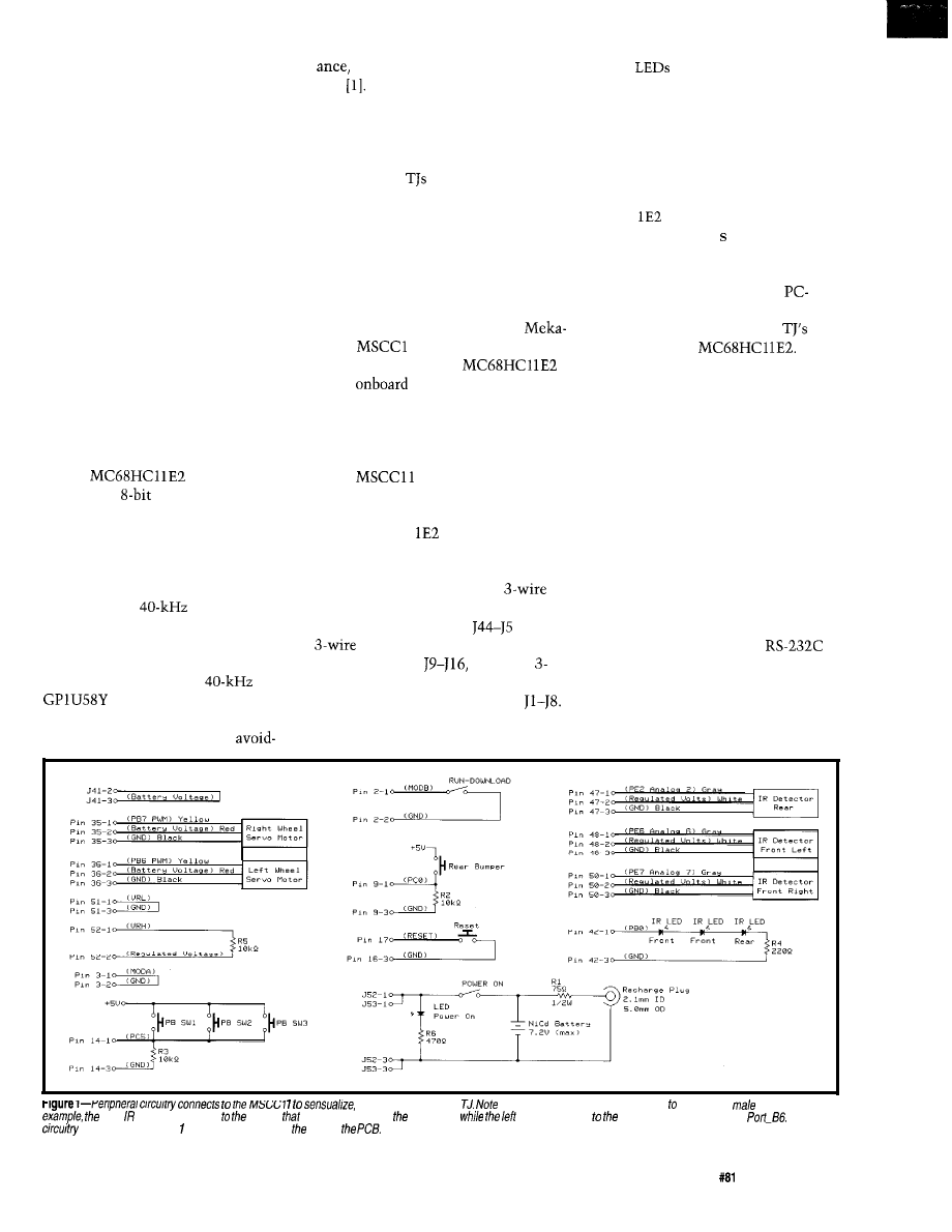
empower, and actuate
carefully how each feature connects a particular
header. For
right defector connects header
brings out pin 50 of processor,
motor connects header at processor pin 36,
The power
connecfs across pins and 3 of Jumper 52 on side of
Circuit Cellar INK@
Issue
April 1997
21
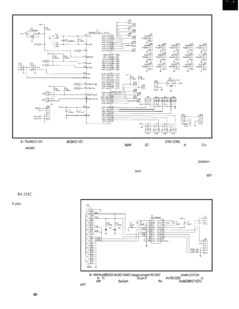
Figure
circuit consists of an
microcontroller surrounded by numerous male headers, designated by
and CON3 with one, two,
and three pins, respectively. These male headers provide easy access to the processor’s powerful
and analog features. They also enable you expand your
sensor and
capabilities.
By
offloading
the conversion hard-
ware from the mobile robot, you can
reduce power consumption and the
cost per robot. Figure 3 depicts the
communication-board circuit.
The MC 145407 charge pump con-
verts the actual voltages. Header J3
provides a standard DB-25 connector
for
communications, and
header J2 connects to a Mekatronix
logic-level, asynchronous serial
communications cable.
MECHANICAL STRUCTURE
Photo 1 illustrates a particular TJ
embodiment. The tabs on the side
pieces make cutting the parts out more
difficult. They add more strength to
the joints, but they aren’t essential.
Of course, you can design a com-
pletely different platform since the
motors, microcomputer, and sensor
circuits work on any body of compa-
rable size. Geometric layout of the IR
emitters and detectors, however, is
critical, but feel free to experiment.
The circular plate mounts on the
side plates like a reverse automobile
22
Issue
April 1997
Circuit Cellar INK@
engine hood. The rounded rectangular
Two slots on the top plate slip onto
slots are wire conduits. The side plate
the “goose” necks in the front
supports the servos, one on each side.
dicular to the floor. Holding the plate
The servos slide into the large
firmly against the vertical ends of the
angular opening in the side’s center.
side pieces, the plate slowly rotates
Four small cross slats hold the side
to the rear as you release the pressure
plates rigidly apart and provide a case
holding the plate vertically.
for the six AA battery pack above the
Two slots in the rear of the plate
nylon skid.
slide over the tabs with circular holes.
Figure
standard voltage
logic
levels (ground 5 signals and vice versa. The
connector gives
levels necessary
communicate
your PC, while
cable connector provides logic levels for
SC/
The diodes’ visual confirmation of communication makes them invaluable for debugging.
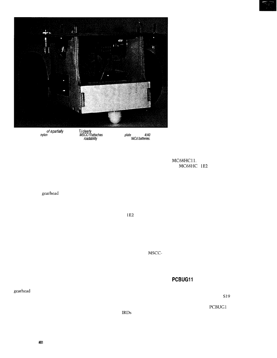
Photo l--This rear view
assembled
illustrates the body assembly and the mounting of
servos, wheels, rear
skid, and switches. The
underneath the
with four
screws.
The battery box above the skid provides stability and
when loaded with six AA
A
0.25”
dowel slipped through the tab
holes locks the top plate into place. A
simple hinge, another cross plate in
front, and a rear latch can eliminate
this complex structure.
MOTORS AND SWITCHES
Any standard servo can be modified
to create a DC
motor. After
removing the back-plate screws, take
off the gear-box cover. Mount a servo
horn on the output shaft and rotate the
servo to the center of its range.
You can do it manually, or for more
precision, you can write a program to
do it automatically for you. In the rest
of the procedure, avoid rotating the
output shaft from its center position.
Remove the output gear and cut the
plastic tab off the output gear. Take
the potentiometer tab out of the out-
put gear so it will not turn the shaft
potentiometer.
TJ possesses three switches mounted
on the top plate in the rear-off/on,
Remount the gear and reassemble
the servo. This almost ruins the servo
as a servo, but instead you have a DC
motor with electronic control!
The 3-pin female connector of the
NovaSoft/Mekatronix MS410 servos or
Aristo-Craft 03-410 Tracker Servo slips
onto the MSCCl l’s male header with-
out modification.
24
Issue
April 1997
Circuit Cellar INK@
download/run, and reset. In the down-
load position, the download/run switch
forces the processor in special bootstrap
mode on reset.
When the processor is in special
bootstrap mode, you can download
programs. In run mode, the processor
changes on reset to single-chip mode
and executes the downloaded program.
In addition to the control switches,
three bumper switches mount on the
front edge of the plate and one on the
back. The MSCCl
board mounts
underneath the plate in four mounting
holes.
WIRING SENSORS
For a complete TJ assembly, all the
switches, discrete components, and
sensors must be wired to the
11 E2 as in Figure 1.
The IR emitters (IRE) and detectors
(IRD) should be mounted on the top
and bottom, respectively, of the top
plate.
The front bumper switches are
wired in parallel. The back bumper is
One IRD can be attached with velcro
underneath the left front of the top
plate, just outside the left side plate.
The other IRD can be mounted on the
right. For the best sensitivity in detect-
ing objects, the
should be splayed
out from straightforward.
wired separately to permit TJ to differ-
entiate a front or back collision.
You can also wire each bumper
switch separately and bring them into
different pins of port C. This approach
enables TJ to determine which bumper
switch or switches have closed, pro-
viding a tactile view of objects about
the robot.
PROGRAM DEVELOPMENT
The next task is to program behav-
iors. TJ can do a surprising number of
actions-avoid collisions, follow walls,
trace out geometric patterns an the
floor, and so forth. You can add more
sensors, but there’s plenty to do with
just the IR and bumper.
For example, a reinforcement learn-
ing program lets TJ learn how to avoid
obstacles using the bump sensors as
negative reinforcement. Only your
imagination and 2 KB of EEPROM
limit what TJ can do!
BASIC, C, and Forth compilers and
assemblers are all available for the
If you’re familiar with
the
1
assembly language,
you can program the servos and the
sensors from the information provided
by the circuit diagrams.
Listing 1 presents a sample servo
driver code in Image Craft C (ICC1 1)
with embedded assembly code for
efficiency.
The servo driver uses OC2 to time
the pulse widths of both servos, ex-
plaining the complication in selecting
thedifferent signal-states. The
servo outputs drive PB6 and PB7 at the
program-generated duty cycle.
The wheels don’t move when the
duty cycle equals 3000 cycles
(1.5 ms).
For the right wheel, full forward equals
4000 cycles and full reverse is 2000
cycles. The left-wheel values have the
opposite values.
After writing a TJ program on your
favorite editor and compiling or assem-
bling the code to Motorola
format,
you’ll want to test it. Here’s where
Motorola’s freeware
1
and the
MB2325 serial communications board
come into play.
Mount TJ on a stand next to your
PC so the wheels don’t touch the table
PC Development Took
No
M
ORE
C
RASH
B
URN
EPROM
Technology 512 k FLASH
DOS Sing/e Board Computer
572
FLASH
disk drive
Mhz CPU 2 Timers
512 k bytes RAM
4 Interrupt Line:
512 k/256 k FLASH 8 Analog Inputs
2 Serial Ports
X-Modem File
24 Parallel Lines
Transfer
INCLUDES DOS Utilities
8 Channels, 12 Bits
6 Conversion Time
Option
Includes Drivers Apps.
1
Price
8 Opto-Isolated’ Inputs
JK micros stems
Cost Effective
for
TO ORDER (510) 2364151
FAX
our WEB site-www.dsp.corn/jkmicro
1275 Yuba Ave., San Pablo,
94806
2 6
Issue
April 1997
Circuit Cellar
Listing l--This code uses OC2 interrupts to control the timing for both servo motors. PO R provides the
pins for the
signals generated by the code. It is designed to operated a using a sing/e-chip
#include
#include
#define PERIOD 40000
#define HALFPERIOD 20000
40,000 cycles = 20 ms at 2 MHz
interrupt-handler servo-hand
void servo
unsigned
current-width;
char signal-state;
char
required in case
is changed while signal
is being produced. Otherwise,
void
shaking in servos results.*/
Initalizes the servos
INTR_OFFO;
Interrupt will not affect
pin
=
=
Set
to 0 first
= 0:
First
int occurs at TCNT=O
current-width = 0:
signal-state = 0;
Initial state of signals
= PORTB
Motors start turned off
= 0x40;
= 0x80;
INTR_ONO:
Enable
interrupt
void
index, unsigned newwidth)
Sets indexed servo to
duty-cycle pulse width
if (index)
= newwidth; else
=
"asrb
Assembler to implement C code
"ldy
"ldd %newwidth
"std
void servo-hand 0
char odd;
int index;
unsigned
pwidth;
signal-state = 0 servo0 on: signal-state = 1 servo0 off
signal-state = 2
on: signal-state = 3
off
0x03:
Only use last 2 bits
index = signal-state:
"lsra
"staa
odd = signal-state 0x01;
pwidth =
if ((pwidth ==
+= HALFPERIOD;
signal-state++:
else
if
+= pwidth:
else if (odd)
+= PERIOD current-width;
PORTB
current-width = pwidth;
signal-state++:
Signal 0 goes on bit 6 of
and Signal 1 is bit 7
Clear
flag
top. Plug the 6-wire serial cable into TJ
load/run switch appropriately and
at one end and the MB2325 at the other
pressing Reset.
end.
Now, execute
1,
invoking
Connect the MB2325 directly to a
the E2 version. Follow the instructions
serial cable or
D-connector on
for changing EEPROM, and load your
the personal computer. Place TJ into
program. Your program should specify
download mode by setting the
EEPROM or RAM addresses.
To execute your program, switch to
run mode and press Reset. Debug and
enjoy!
AUTONOMOUSANDAFFORDABLE
My students and I have demon-
strated that, through construction, an
autonomous, programmable, mobile
robot can be affordable.
An assembled version of TJ sells for
$189, and an unassembled kit is avail-
able for $129.
Many thanks to the students in the
Machine Intelligence Laboratory at
the University of Florida who assisted
in the design of Erik de la
Scott
and Chris Gomez de-
signed the
computer board.
The platform evolved from ideas by
Scott. Ivan Zapata developed the soft-
ware. Scott and Ivan also constructed
and
tested prototypes.
Keith Doty has been a professor at the
University of Florida, researcher, and
industrial consultant for over 25 years.
His current interests include
based, sensory-driven autonomous
mobile robots and applied machine
intelligence. You may reach Keith at
TJ
kits and assembled versions
NovaSoft/Mekatronix
4813 NW 19 Pl.
Gainesville, FL 32605
(352) 392-4951
Fax: (352) 392-4976
Motorola
Fax: (602) 3028157
BBS: (512) 891-3733
crc@crc.sps.mot.com
www.mcu.motsps.com/freeweb/
404
Very Useful
405 Moderately Useful
406 Not Useful
This book, describes how to
assemble and build Stiquito,
provides information on the
design and control of legged robots,
illustrates its research uses, and includes the
robot kit. The experiments in the text lead
the reader on a tour of the current state of
robotics research. The hobbyist with some
electronics background will also find
this book challenging.
Contents:
Preface
l
Stiquito Introduction and History
l
Walking Robots
l
Control of Walking Robots
l
Using Stiquito for Research
l
The Future of
Stiquito
l
Bibliography
l
Appendixes
250
pages.
7 x
Hardcover
Robot kit. April 1997.
O-8186-7408-3.
# BP07408
$28.00
$35.00 List
IEEE
S O C I E T Y
Order using
secure
Online Catalog
or call
With Cimetrics’
you can link together up to 250 of the most popular and
microcontrollers
68332,
The
is:
A high speed
baud) multidrop
master/ slave RS-485 network
Compatible with your
microcontrollers
Reliable- Robust
CRC and sequence
number error checking
Low microcontroller resource
requirements (uses your chip’s built-in serial
Friendly- Simple-to-use C and assembly
language software libraries, with demonstration
programs
Includes network software,
network monitor, and RS-485 hardware
PLAN is an asynchronous
adaptation of IEEE
l
55 Temple Place
l
Boston, MA 0211 l-1300
l
Ph 617.350.7550
l
Fx 617.350.7552
Circuit Cellar INK@
issue
April 1997
2 7
Payne
A Networking Primer
Part 3: Interconnecting Devices
stallment, I cover
operation of devices that
interconnect networks. Each of these
devices-repeaters, bridges, switches,
routers, brouters, and gateways-fills a
specific need of interconnecting
The downside to using repeaters in
an Ethernet environment is that all
signals are propagated to all segments.
As new devices are added to a segment,
the total network traffic increases.
Limitations, such as the physical
length of the network, are overcome
by these technologies. And, they enable
multiple
to communicate even
though each may use different access
methods and protocols.
The limitations of the usable band-
width of your media-access method
must be understood. As I pointed out
in Part 2, Ethernet-usable bandwidth
shouldn’t exceed 45% utilization. To-
ken Ring-usable bandwidth shouldn’t
exceed 80% utilization.
Driving the need to interconnect
networks are interoffice communica-
tion, E-mail, and centralized file and
print sharing. Centralized LAN man-
agement helps in problem determina-
tion and resolution.
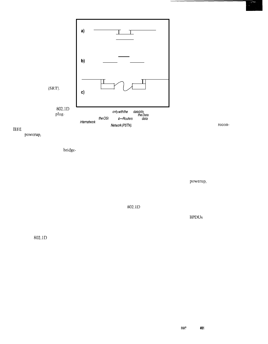
BRIDGES
Bridges operate at the Data Link and
Physical layers in the
model and
interconnect
They bridge data
between two independent
as
shown in Figure b.
REPEATERS
Figure la shows a simple repeater. It
operates at the Physical layer of the
model and overcomes the physical
distance limitations of the wiring
media. It can also increase the number
of devices allowed on a LAN segment.
Bridges filter data passed across
them. Each frame’s Media Access
Control (MAC) address is checked to
determine whether it should be for-
warded or not. Frames with the same
MAC address as the LAN they’re oper-
ating on are ignored by the bridge.
The repeater is not intelligent. It
In this way, a bridge isolates each
regenerates the received signal and
LAN from collisions occurring on other
retransmits it along another segment.
Such isolation creates what is
It deals only with the raw data bits and
referred to as a “collision domain.”
the physical aspects of the LAN media.
In a proper bridge setup, only 20%
A repeater can only interconnect
of the LAN traffic forwards. The re-
LAN segments using the same
maining 80% should be local.
access
protocol. If one LAN segment
uses the Ethernet media-access proto-
col and another Token Ring, they can-
not be interconnected with a repeater.
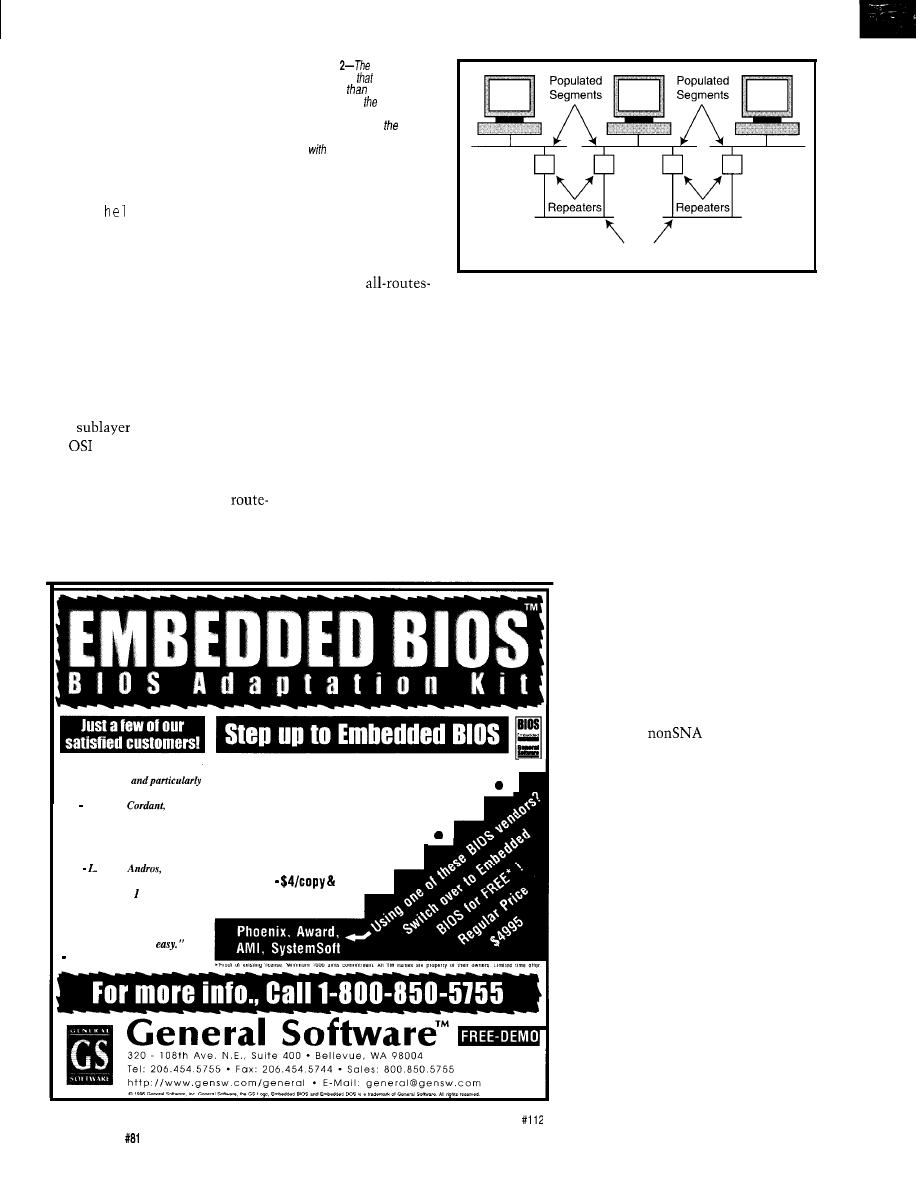
In the Ethernet environment, repeat-
ers must follow the
rule, depicted
in Figure 2. The rule states that a LAN
can comprise a maximum of five seg-
ments using a maximum of four repeat-
ers. Also, only three of these segments
can be populated with devices.
The two nonpopulated segments
typically extend the network’s physical
length. These so-called link segments
are found in places such as the wiring
between floors in a building and be-
tween wiring closets.
In
Ethernet environments,
every hub acts as an active multiport
repeater. The interconnection of these
hubs must also follow the 5-4-3 rule.
By contrast, in a Token Ring net-
work, every connected device is an
active repeater, regenerating received
signals. The 5-4-3 rule doesn’t apply.
28
Issue
April 1997
Circuit Cellar INK@
Bridges only forward frames
containing user data. Frames
used for tasks such as network
management aren’t forwarded.
Each forwarded frame must have
a valid checksum and not be
addressed to the bridge itself.
Bridges are rated by the num-
ber of frames they can forward
per second [i.e., their filtering or
forwarding rate). There are three
basic types of bridges-transpar-
ent, source routing, and source
routing transparent
TRANSPARENT BRIDGES
A transparent bridge is de-
fined by the IEEE in the
specification. This true
and-play device can be used by
any protocol adhering to the
802 specifications.
LAN Segment
LAN Segment
(Ethernet)
(Ethernet)
Repeater
Bridge
LAN1
LAN 2
LAN A
LAN B
(Ethernet)
(Ethernet)
Router
Router
Public Switched
Telephone Network
(PSTN)
Figure la--Repeater. deal
raw
and the physical
aspects of fhe media. b-Bridges operate at both
Link and
Physical layers in
model.
deliver
packets across
an
via a telephone inferconnect, more correctly known as a
Public Switched Telephone
source. It then forwards the
packet to the redundant bridge.
The redundant bridge sees
the frame packet and assumes it
originated on the same side of
the bridge it was received on. It
then takes the frame packet and
forwards it back to the originat-
ing LAN segment. This process
continues indefinitely.
The spanning tree protocol
overcomes this infinite loop by
selecting one redundant bridge
as the designated bridge and the
other as the backup.
The protocol uses a special
frame packet, the Bridge Proto-
col Data Unit (BPDU), to com-
municate between bridges. The
BPDU exchanges enable the
network to dynamically
On
transparent bridges
forward all frames received on each
segment. As a frame is received, the
source address is stored in a
internal table. The bridge thus learns
the address for the segment where the
frame was received, which is why it’s
sometimes called a learning bridge.
All frames on this known segment
not having the same address for both
their source and destination are for-
warded. The addresses of each segment
are stored in a filtering database inter-
nal to the bridge. The database uses a
flat-addressing scheme, so every device
has a separate address entry.
Transparent bridges can operate in
one of five possible states-disabled,
blocking, listening, learning, and for-
warding. Each state is defined by the
IEEE in the
specification.
A disabled bridge doesn’t forward
frames or learn. This state is entered
and exited via management commands
sent to the bridge.
Blocking bridges also do not forward
frames or learn. The bridge continues
to participate in all spanning tree pro-
tocol operations.
When listening, a bridge enters the
learning state. All bridge ports are
active, but no evaluation of the frame
MAC addresses occurs. This transi-
tional state occurs when the bridge is
brought from the blocking or disabled
state into the frame-forwarding state.
Once a bridge is in the learning
state, it prepares to forward frames. The
MAC address of each frame received is
added to the filtering database. This
state is entered through operation of
the spanning tree protocol.
In the forwarding state, the bridge
actively participates in frame-forward-
ing. Each bridge port is still learning
and adding new entries as they occur
to the filtering database.
SPANNING TREE PROTOCOL
This protocol is a bridge-hierarchy
protocol (see the IEEE
specifica-
tion for details] that lets bridges com-
municate with other bridges on a LAN,
enabling the network to detect when
bridge or segment failures occur. In this
event, the network dynamically recon-
figures the routes and bypasses the
failed segment or bridge.
Primarily, this protocol organizes
routes between redundant bridges to
eliminate bridging loops. Redundant
bridge paths in a transparent bridge
environment can be fatal.
So, after the primary bridge receives
a frame packet, it updates its filtering
database to point to the frame packet’s
Bridging loops (see Figure 3) are due
to the primary and redundant bridges
continually updating their filtering
databases. Because of propagation de-
lays on the media, one bridge receives
the frame packet before the other one.
figure after a failure.
To assist in reconfiguration, each
bridge has a unique eight-byte ID num-
ber. The ID’s first two most significant
bytes are assigned by the network ad-
ministrator. The last six bytes are the
manufacturer’s assigned MAC address
for the bridge-internal port adapter.
The spanning tree protocol uses this
ID to select the designated and back-
up bridges. On
each bridge
transmits a BPDU with its unique ID
on all ports.
If the bridge receives a BPDU with a
lower bridge ID than its own, it stops
transmitting its own BPDU and starts
forwarding the BPDU with the lower
bridge ID. The
are transmitted
at 2-s intervals. All bridges can respond
to their own specific address as well as
a bridge’s assigned multicast address.
Topology changes when an admin-
istrator issues a change command or
through a segment or bridge failure.
During a topology change, all bridges
stop forwarding frame packets to pre-
vent temporary loops.
SOURCE-ROUTING BRIDGES
The source-routing bridge doesn’t
maintain a filtering database like the
transparent bridge. Instead, each device
Source routing is an IBM specifica-
tion that relates to data transmission
in an IBM SNA environment. It is
typically found only in Token Ring
networks as depicted in Figure 4.
Circuit Cellar
Issue
April 1997
29
on the network maintains its own
dynamic table of routes.
When data needs to be transmitted
to another device, the transmitting
device performs a route-determination
operation. This operation, which builds
the route table internal to the device,
consists of the transmitting device
sending a
1 o packet to the destina-
tion device.
The transmitting device takes the
route information from the first reply
back from the destination device and
adds it to the route table. All other
replies from the destination device are
ignored.
IBM refers to this process as an
exchange identification (XID) packet
within the Logical Link Control (LLC)
sublayer. As I explained in Part 2, the
LLC
within the Data layer of
the
model handles error control,
flow control, framing, and MAC ad-
dressing.
A problem inherent in the
determination process is that it gener-
ates massive amounts of network
traffic. To resolve this, IBM developed
Figure
Ethernet 5-4-3
rule states
fhere can be
no more
five physical
segments in LAN, a
maximum of four repeaters,
and only fhree of five
segments can be populated
nodes.
two
states for a
source-route bridge.
In the
broadcast state, all bridges forward all
packets. But, this system has problems
on a LAN composed of multiple Token
Rings interconnected by multiple
bridges.
For example, suppose two Token
Rings are connected via two bridges (a
common scenario in a network where
redundancy is used for fault tolerance).
The destination ring receives two
frames for each frame generating on
the source ring. The amount of traffic
grows exponentially as more rings
interconnect and as more devices enter
each ring.
“We’re
impressed by the level of
documentation
by
the
readability of the code”
M. Ryan,
Inc.
“Fast,
flexible,
high-quality
code, and excellent
technical support.”
Allen,
Inc.
“Personally,
found the
Adaptation Kit and tool set very
straightforward to use, making
the BIOS development
process relatively
S. Chaplin, Software Engineer.
Unpopulated Segments
Includes our award-winning Run-From-Rom DOS
I
Includes Flash Disk for popular Flash parts
l
Over 300 easy configuration options
BIOS Kit includes full source code
l
Royalties
down
l
In the single-route-broadcast state,
on the other hand, only the bridge
forwards packets. The redundant
bridges remain in the all-routes-broad-
cast state but ignore all data packets
with the single-route-broadcast bit set.
For this system to work, every device
on the ring must be configured to trans-
mit all route-determination packets as
single-route broadcasts.
SOURCE-ROUTE TRANSPARENT
BRIDGES
The source-route transparent (SRT)
bridge incorporates the features of both
transparent and source-route bridges.
It acts as a source-routing bridge for
frames carrying source-routing infor-
mation. When it receives a frame which
doesn’t have source-routing informa-
tion, it acts as a transparent bridge
with a filtering database.
The SRT bridge is usually found in
mixed environments with IBM SNA
devices and
devices, but pres-
ently, no standards exists for it. The
various manufacturers of these bridges
implement them as they see fit.
SWITCHES
Switches, a newer LAN technology,
are a hybrid between a repeater and a
bridge.
A classic bridge operates by bringing
each received frame packet into cache
memory. After the address information
is processed by the bridge CPU, the
frame packet is either discarded or
forwarded. This process adds a consid-
erable amount of latency to each for-
warded message.
A switch doesn’t cache the entire
message. Instead, it only processes the
MAC address header on the frame
packet. No further processing is done.
3 0
Issue
April 1997
Circuit Cellar
INK@
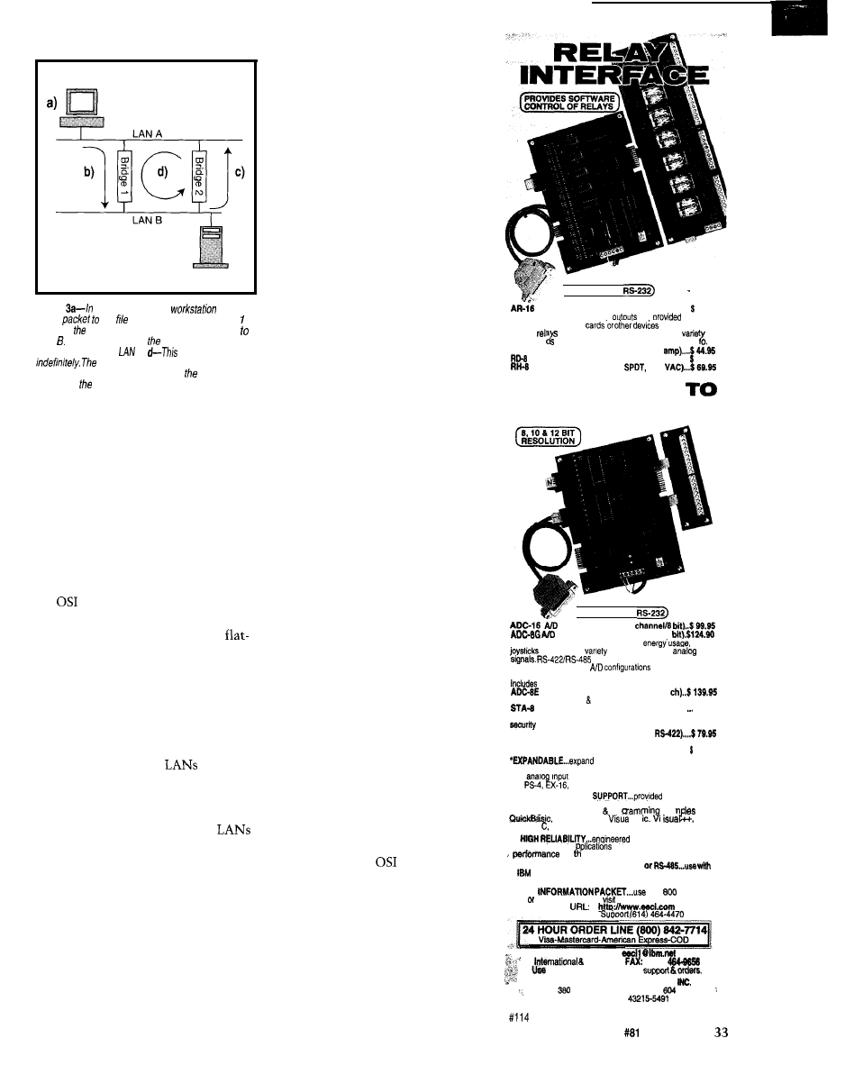
Workstation
File Server
Figure
a bridging loop, the
sends a
frame
fhe server on LAN 5. b-Bridge
receives frame packet on LAN A and forwards if
LAN c-Bridge 2 receives frame packet on LAN
B and forwards it fo
A.
cycle repeats
spanning free protocol prevents fhis
infinite loop by defining one bridge as designated
bridge and other as the backup.
Switches
therefore give a much
higher packet-per-second throughput.
They still provide the basic traffic fil-
tering needed on a multisegment LAN
but at a much higher throughput.
ROUTERS
Routers deliver data packets across
a internetwork independent of the
communications media (see Figure
lc).
They work up to the Network layer of
the
model.
Routers use software addresses that
are hierarchical as opposed to the
addressing scheme used in bridges.
The flat addresses used in a bridge
define only a single hardware address,
whereas hierarchical software address-
es describe the entire network.
Routers can convert a data packet
from one protocol to another. This
feature is useful if two
need to
be connected but are in different geo-
graphic areas.
A technique known as tunneling is
sometimes used to connect two
across an analog telephone line. The
originating LAN protocol data packet
is encapsulated in the transport proto-
col and sent across to the other router.
On receipt, the transport protocol is
stripped from the encapsulated data
packet, leaving the original data packet.
Routers provide two types of deliv-
ery services-connection-oriented and
connectionless- or packet-oriented.
Connection-oriented services guar-
antee packet delivery. The existing
X.25 Public Switched Telephone Net-
work (PSTN) provides the most com-
mon connection-oriented services.
With this type of service, a router
must establish a connection with a
remote router before transmitting data
packets. This connection becomes
fixed until it’s no longer needed.
All transmitted data packets arrive
at the receiving end in the transmitted
order. The originating router informs
the receiving router of the maximum
packet size used in the communica-
tions session.
An analogy to this type of service is
a telephone call. You can’t begin com-
municating with the other party until
they answer the phone. And, when the
other party answers, communication
begins only if you both speak the same
language.
Connectionless or packet services
do not guarantee delivery of any data
packets. Frame relay is the most com-
mon connectionless or packet service.
Each data packet is routed dynami-
cally, based on the network address.
Transmitted packets arrive at the re-
ceiver in no specific order. At the re-
ceiving end, they are reassembled
based on a sequence numbering
scheme.
Bandwidth is allocated dynamically
to all users. If network traffic is high,
packet services degrade equally to all
users. No one is denied network access.
ROUTING PROTOCOLS
Routers use very specific protocols
to communicate with each other. They
discover routes, update routing infor-
mation, send alerts about traffic con-
gestion, and advertise the cost of each
path in hop counts. (A hop refers to the
passing of a packet from one router to
another.)
Routing protocols should not be
confused with the
network-layer
protocols. Instead, they are based on
one of two distributed routing algo-
rithms known as the distance-vector
and link-state algorithms.
The distance-vector algorithm cal-
culates routes based on information
gathered from neighboring routers.
Due to its simplicity, this algorithm
( C
ONNECTS
TO
RELAY INTERFACE (16 channel) . . . . . . . . . . . . 69.95
Two 8 channel (TTL level)
are
for
connection to relay
(expandable
to 128
of
relays car
using EX-16 expansion cards). A
and relays are stocked. Call for more in
AR-2 RELAY INTERFACE (2 relays, 10
REED RELAY CARD (6 relays, 10 VA) . . . . . . 49.96
RELAY CARD (10 amp
277
A N A L O G
D I G I T A L
(
C
O
NNECTS TO
CONVERTER’ (16
CONVERTER’ (6 channel/IO
Input voltage, amperage, pressure,
light,
and a wide
of other types of
available (lengths to 4,000’).
Call for info on other
and 12 bit
converters (terminal block and cable sold separately).
Data Acquisition software for Windows 95 or 3.1
TEMPERATURE INTERFACE’(6
Includes term. block 8 temp. sensors (-40’ to 146’ F).
DIGITAL INTERFACE’ (6 channel) . . . . . . $99.96
Input on/off status of relays, switches, HVAC equipment,
devices, keypads, and other devices.
PS-4 PORT SELECTOR (4 channels
Converts an RS-232 port into 4 selectable RS-422 ports.
CO-422 (RS-232 to RS-422 converter) . . . . . . . . . . . . . . . . . . . 39.96
your interface to control and
monitor up to 512 relays, up to 576 digital inputs, up to
128 anal
inputs or up to 128 temperature inputs using
the
ST-32 &AD-l6 expansion cards.
l
FULL TECHNICAL
over the
telephone by our staff. Technical reference &disk
including test software pro
exam
in
GW Basic,
Basic.
Turbo Assembly and others are provided.
l
for continuous 24
hour
industrial a
in
with 10 years of proven
e energy management field.
*CONNECTS TO RS-232, RS-422
and compatibles, Mac and most computers. All
standard baud rates and protocols (50 to 19,200 baud).
FREE
our
number,
Fax E-mail to order, or
our Internet on-line catalog.
Technical
Internet E-mail:
Domestic
(614)
for information, technical
ELECTRONIC ENERGY CONTROL,
South Fifth Street, Suite
Columbus, Ohii
Circuit Cellar INK@
Issue
April 1997
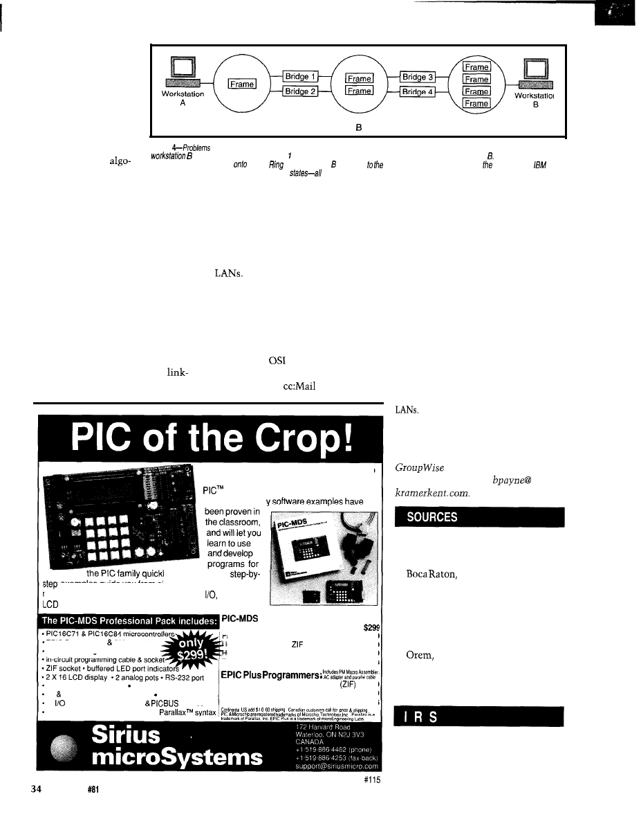
was
the first one imple-
mented.
But, its biggest disad-
vantage is the amount
of time it takes for all
n
routers in the network
to exchange information
Token Ring
Token Ring
A
Token Ring
(i.e., the convergence
C
time).
Figure
arise when multiple Token Rings are connected with redundant bridges. Workstation A sends a frame
packet to
The link-state
on Token Ring A. Both bridges and 2 place copies of fhe original frame packet onto Token Ring Bridges 3 and 4 p/ace
rithm calculates routes
copies of replicated frames
Token
C. Workstation responds original frame packet as we// as three copies.
resolves
this problem via two possible router
routes broadcast and single route broadcast.
based on information
actively learned about the network.
These routers build their route tables
by discovering their neighbors.
BROUTERS
Once the router has discovered its
neighbors, this information is sent to
all neighboring routers in a special
link-state packet (LSP). Each of the
neighboring routers then forwards the
LSP to all the other routers in the
network.
A brouter is an intermediate device
which combines the functionality of a
transparent bridge with a router. Proto-
cols which cannot be routed (e.g., IBM’s
SNA) are bridged to interconnecting
Protocols which can be routed
are passed through the router.
GATEWAYS
Therefore, all the routers in the
Gateways are software-based
p r o -
network can converge much more
grams that translate between incom-
quickly after a topology change. The
patible protocols. They function at all
Open Shortest Path First (OSPF) rout-
layers of the
model.
ing protocol is an example of a
A good example of a gateway is one
state algorithm protocol.
which converts
to Simple Mail
The PIC-MDS includes everything you need to
start programming the mid-range family of
microcontrollers. The detailed training
manual and man
y and easily. Our
examples guide you from simple programs to complex
‘outines, including keypad scanning, serial
interrupts,
display, A/D conversion, data logging, and more!
Systems:
Professional Pack Complete!
EPIC Programmer PM assembler
Professional Board (no programmer)
$256
detailed training manual with disk
obbyist Pack (kit, no
socket, ‘C84 only) $196
obbyist Board (kit, no programmer)
$139
Teacher’s Manual/Lab Packs
Call for details
256 byte serial EEPROM crystal/resonator socket
EPIC Plus Professional Programmer
$99
5V variable DC power supplies AC adapters
EPIC Plus Programmer (no ZIF socket)
$79
all
pins on screw terminals
connector
EPIC Plus Hobbyist programmer (kit)
$65
all code examples in Microchip and
Transfer Protocol (SMTP), providing a
connection to the Internet. Gateways
are usually very CPU and memory
intensive.
YOU’RE CONNECTED
This series of articles should give
you a basic but complete overview of
the principles involved in networking
and intemetworking. The information
I’ve presented only scratches the sur-
face of the technologies involved. Each
area could fill a separate book.
I trust I’ve given you enough infor-
mation about LAN operating principles
that I’ve removed the veil of black
magic that most people associate with
q
Bill Payne has many years’ experience
as digital design engineer. He is also a
Novell Master CNE, Novell Master
CNE, and a Novell CNS.
You may reach Bill at
IBM
cabling standards
IBM Corp.
1000 NW 51
St.
FL 33432
(407) 443-2000
Fax: (407) 443-4533
Novell
Novell, Inc.
1555 N. Technology Way
UT 84057-2399
(801) 222-6000
Fax: (801) 861-3933
www.novell.com
407
Very Useful
408 Moderately Useful
409 Not Useful
Issue
April 1997
Circuit Cellar INK@
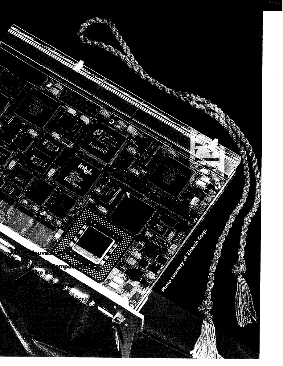
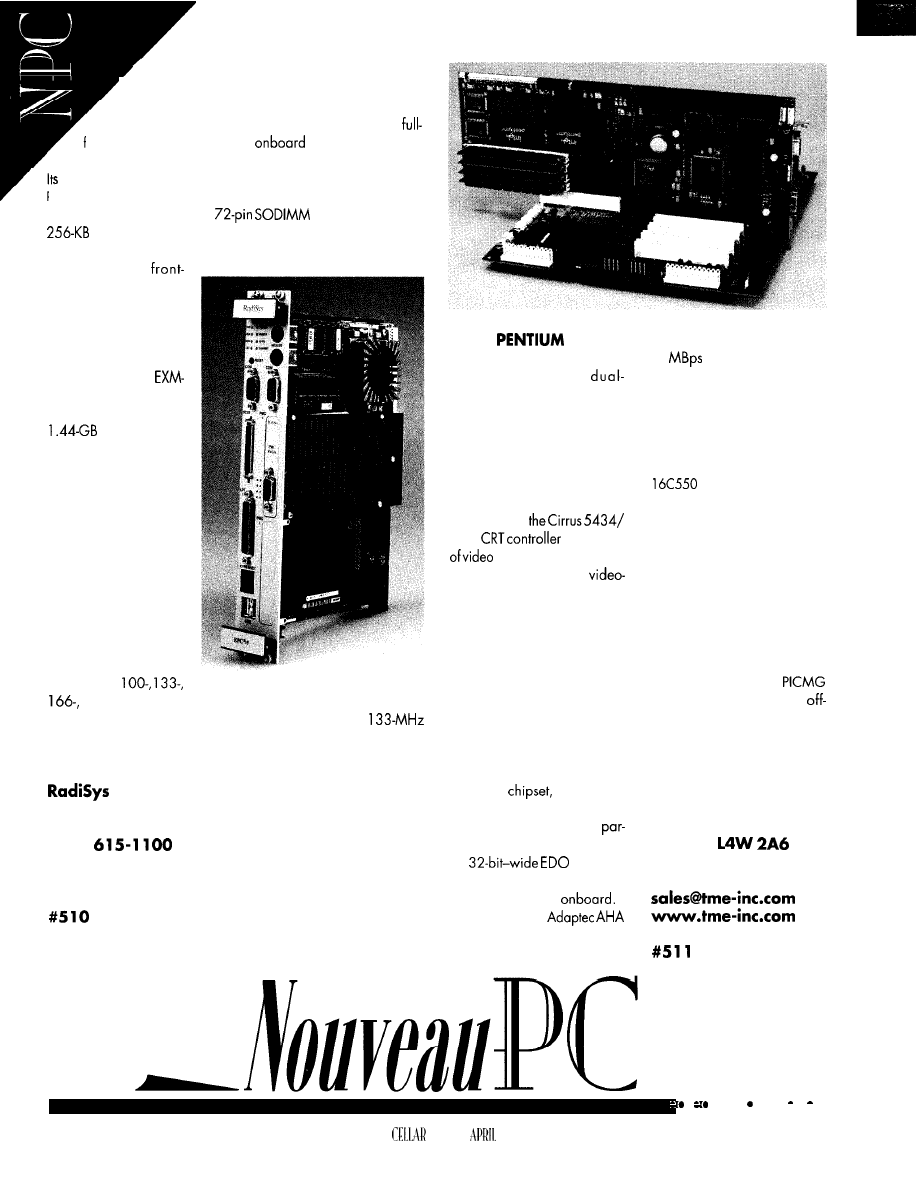
EMBEDDED PC WITH VME BUS
.
The EPC-9 is a dual-slot PC/AT-compatible
board with a Pentium processor that’s designed for
high-performance embedded applications. It is a
featured VME-bus board with
Ethernet and SCSI II,
IDE hard drive, USB, and two PMC slots for PCI-bus expansion.
modular processor design provides for a field upgrade to a
Pentium Pro processor.
The EPC-9 features four
memory sockets,
secondary cache, an autosensing 1 O/l OOBaseT Ethernet
controller with front-panel RJ-45 connector, and a fast SCSI II
controller with
panel connector. I/O is
accomplished via two
USB ports, one parallel
and two serial ports,
mouse and keyboard
controllers, and an
bus expansion.
An optional 2.5” IDE
hard drive fits
on the two-slot EPC-9, as
does an optional SVGA
PMC module. By offer-
ing video in a low-cost
PMC form factor, the
EPC-9 provides an opti-
mal video solution that
can beeasilyupgraded.
Should an application
not require video, two
PMC slots are available
for other functions.
The EPC-9 is avail-
able with a
or 200-MHz Pentium-processor-based module which is
upgradable to a Pentium Pro module. The EPC-9 with a
Pentium processor and 8-MB DRAM sells for $3527 in quantities
of 100.
Corp.
5445 NE Dawson Creek Dr.
Hillsboro, OR 97124
(503)
Fax: (503) 615-l 150
www.radisys.com
DUAL
SBC
The 2108 single-board
computer combines
Pentium processing powerwith
a variety of high-performance
features. High-level graphics is
achieved via the Chips and
Technologies65548 CRT/Flat-
Panel Controller with bit-block
transfer and GUI accelerator
featuresorvia
5446
with 2 MB
memory. The flat-panel
interface features a PC
input connector, while the CRT
interface has a feature connec-
tor. Both graphics controllers
are on the Local bus, providing
optimal graphics performance
for imaging and multimedia
applications. Resolutions up to
1280 x 1024 pixels are sup-
ported with a full 1 MB of video
RAM.
The 2 108 uses the Triton II
82340HX
which sup-
ports USB and infrared I/O.
Memory is supported with
ityorerrorcorrection to5 12 MB
of
D R A M .
Up to 5 12 KB of L2 synchro-
nous cache is also
A RISC-based
2940 Ultra Fast SCSI interface
provides data transfers up to
40
in synchronous or
asynchronous modes. Com-
bined via a PCI bus is Intel’s
1 O/l OOBaseT LAN controller
with support drivers for a num-
ber of operating systems.
The 2 108 includes two full
serial ports, printer port
with ECP support, and floppy
and enhanced IDE support as
part of the standard I/O pack-
age. Embedded PC and system
BIOS features include extensive
power management, tempera-
ture sensing for processorclock
speed reduction, no fan for
speeds up to 133 MHz, op-
tional fast boot, and boot with-
out keyboard. A full
interface facilitates many
the-shelf PCI or ISA products.
Pricing for some models starts
at $995 in single quantities.
TME
5149 Bradco Blvd.
Mississauga, ON
Canada
(905) 625-3203
Fax: (905) 625-3717
l
36
CIRCUIT
INK
1997
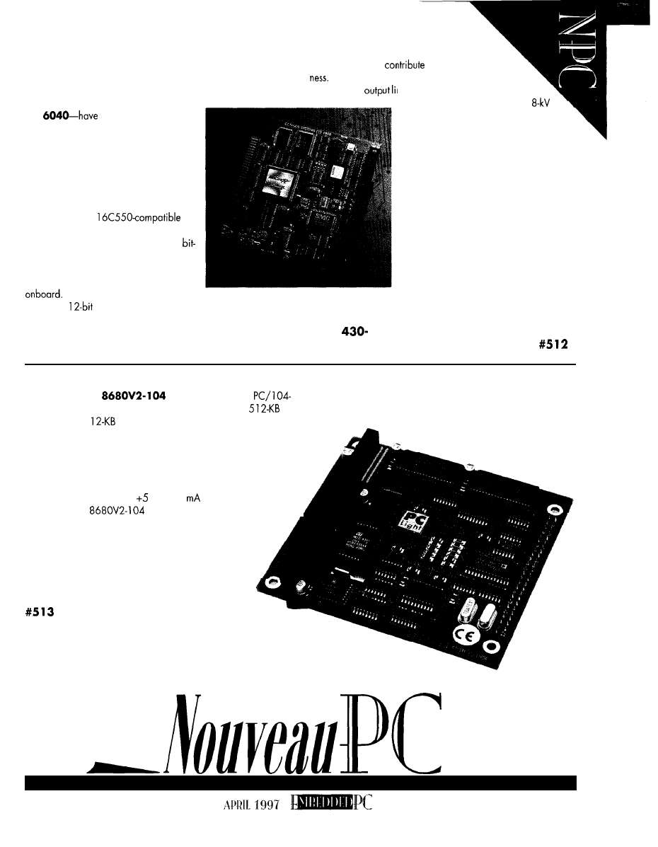
SINGLE BOARD COMPUTER
The new PC Microcontroller series of single-card industrial
computers combines industry-standard PC architecture with indus-
trial-class I/O and an extensive suite of embedded software. The
Several factors
In addition to the
the input and
first two products in the family-the 6050
and
a robust feature set thot
includes digital, analog, and serial I/O.
These cards are ideal for a wide variety of
applications, including machine control,
GPS, PLC monitoring, weighing machines,
point-of-sale systems, and operator inter-
face.
nes on the cards are protected. The
serial ports can withstand an
discharge without failure, and the exter-
nal interrupts are optoisolated to protect
the card from high-voltage transients.
The software suite includes diagnostics,
networking, DOS 6.22, and CAMBASIC,
a fast multitasking control and data-acquisi-
tion language. Embedded in flash memory,
the PC Microcontroller software suite elimi-
nates laborious tasks such as writing hard-
ware drivers. In addition, the family is
compatible with many of the popular real-
time operating systems (e.g., QNX), as
well as most other PC software tools.
In small quantities, the 6050 and 6040
sell for $374 and $562, respectively.
10 lines of
analog I/O. The flash-file system on both cards
Octagon Systems
lets users save program and data files in the same manner as with
65 10 W 91 st Ave.
l
Westminster, CO 80030
a hard disk. The cards can operate stand alone or be expanded
(303)
1500
l
Fax: (303) 426-8 126
via the ISA
bus.
The 6050 and 6040 microcontrollers
both feature two
se-
rial ports, an enhanced parallel port, two
optoisolated interrupts, 24 lines of
programmable DIO, keyboard and speaker
ports, real-timeclock, watchdog timer, 1 -MB
flash, 2-MB DRAM, and an AT battery
The 6040 microcontroller adds
to the cards’ rugged-
-40 to 85°C temperature range,
ULTRA-COMPACT PC/ 104 CPU
The
PC
light
is an ultracompact
compatible computer from Groupe Erim. It includes
or
1 -MB DRAM, 5
or 1 -MB flash memory (300 KB for a RAM
drive with BIOS, DOS, and drivers already installed), a video
controller for direct connection to a 320 x 240
(‘/
A
VGA) LCD flat-
panel display, and an RS-232 serial port. Also included is an
interface for a 64-key matrix keyboard or XT keyboard and a real-
time clock backed up by an external lithium battery. Power
requirement for the unit is
V at 250
max.
The PC Light
is distributed in the U.S. by Gespac.
,
Gespac
50
W.
Hoover Ave.
Mesa, AZ 852 10
(602) 962-5559
Fax: (602) 962-5750
3 7
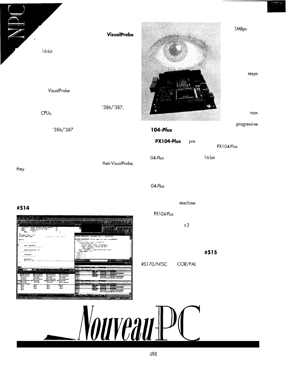
‘x86 SIMULATOR
.
Systems and Software is shipping a compact
disc that contains two versions of the
‘x86 Simulator.
The Trial and Standard Editions are
b o t h
’
source and symbolic debuggers for 32-bit protected-
mode and
real- and protected-mode embedded C and
assembly applications.
Also included is an extensive series of tutorials and additional
information designed to educate the user about the functions,
features, and capabilities of using a simulator as a debugger. Their
goal is to explain the function of a simulator and how it works.
The Trial Edition provides all the capabilities necessary to help
you evaluate the
Simulator. Also, it enables you to
teach about how to use simulators as debugging tools and how
their functions can be used in developing embedded applications.
The Standard Edition offers simulation of the
‘486,
and Pentium
a command window, unlimited trace, and an
extensive list of peripheral models, as well as a printed manual. The
Trial Edition is a fully functional subset of the Standard Edition. It
simulates only the
processor, it has no command
window, trace is limited to 100 lines, and no printed manual or
technical support is provided.
The Trial Edition is currently offered
free
(though shipping cost
may be applied to some requests and to all express-shipment
requests). The user may also upgrade to the more capable
Standard Edition for $495. When users upgrade
can unencrypt the Standard Edition already present on the CD.
Systems and Software, Inc.
18012 Cowan Ave., Ste. 100
Irvine, CA 92714
(714) 833-1700
l
Fax: (714) 833-1900
PC/
FRAME GRABBER
The
is a
cisevideo-capture module with
PCI-bus compatibility in a
PC/l
package. Its high
accuracy and low pixel jitter
make it ideal for industrial and
commercial machine-vision
applications. The compact
PC/l
format simplifies
integration and allows for a
compact, rugged, cost-effective
embedded PC-based
vision system.
The
features 256
gray-scale levels (8 bits) with a
maximum pixel jitter of
ns.
It also has four multiplexed
video inputs with automatic
video-format detection and
switching, as well as continu-
ous, triggered, or software-ini-
tiated frame capture. It includes
and
compatibility. Vertical and hori-
zontal cropping and pixel deci-
mation reduce memory and
data-transfer demands. Other
features include a PCI-bus mas-
ter design for real-time image
capture at rates up
to 13
to sys-
tem RAM or VGA
display, as well as
horizontal and ver-
tical sync output for
precise synchroni-
zation of the frame
grabber and cam-
era. Instant
chronization and
dual strobe outputs
make working with
resettable (asyn-
chronous) cameras
e a s y . O p t i o n a l
support for
interlaced video
from
s c a n c a m e r a s w i t h i m a g e
lengths up to 1024 lines is also
provided.
The
comes with
complete software support for
DOS and Windows 3.1,
32-bit Windows 95, and Win-
dows NT applications, as well
as compatibility with Visual
Basic and C/C++ compilers
from Borland and Microsoft.
The unit sells for $895.
Imagenation
P.O. Box 276
Beaverton, OR
97075-0276
(503) 64 l-7408
Fax: (503) 643-2458
www.imagenation.com
38
CIRCUIT CELLAR INK
1997

Moving
into the
world
wasn’t
easy.
overcome the limitations of the desktop and industrial
also developed
a
that hosts
and
boards
bridges to
ISA,
and
32.
is a new high-performance
embedded-bus standard gaining momen-
tum among industrial-computer suppliers
and users. Combining Intel PCI signalswith
packaging, it offers a rugged
high-performance alternative to desktop
PCI designs.
To better understand
advantages, let’s start with a brief
early Local-bus implementations and speci-
fications, and then move on to more techni-
cal
of
both PCI and
also cover possible applications for this
new standard.
I N T H E B E G I N N I N G
PC manufacturers were constantly striv-
ing to improve the performance of
graphics adapters residing on the PC’s
expansion bus. Early adapter designs had
to process low-level commands from the
microprocessor.
The first step towards increasing through-
put was adding intelligence to the adapter
card so it could handle high-level com-
mands and free up the microprocessor
from screen-intensive operations. The ISA
expansion bus had become a bottleneck as
well, limited to
transfersat 8-l 0 MHz.
The next step was to move the intelligent
video adapter from the slower expansion
bus to the processor’s Local bus and opti-
mize the design to minimize or eliminate
the wait states inserted in each bus cycle.
For better or worse, the birth of Local-bus
designs had begun.
B U S
Lack of an existing standard for inter-
connecting Local-bus devicesand PC archi-
tecture led a group of video-adapter manu-
facturers called the Video Electronic Stan-
dards Association (VESA) to come up with
the W-bus specification. The first version
defined two methods of interfacing to the
processor’s Local bus.
type A described a direct-connect
scheme. The device connects directly to the
processor’s bus structure, requiring no
additional system board logic.
type B defined a buffered approach.
The Local bus was electrically isolated from
the processor bus
by
a
buffer/driver, which
appeared as one load to the processor bus.
Both approaches achieved a maximum
data-transfer rate of 132
at 33 MHz
during burst reads (cache-line fill opera-
tions) and 66
on 32-bit write trans-
fers.
So, why didn’t the VESA
become
the prevalent standard?
First, it was rather shortsighted, being
designed around the Intel ‘486.
generation processors needed the bus in-
terface logic redesigned. bus didn’t
have clear electrical-design guidelines to
ensure bus-design integrity.
As well, the VESA VL V. 1 .O
called
for automatic system-configuration support.
But, it didn’t define the location or format of
Local-bus device-configuration registers.
E N T E R P C I B U S
Aiming to provide
a
clearly
defined and
longer-term solution, Intel released the
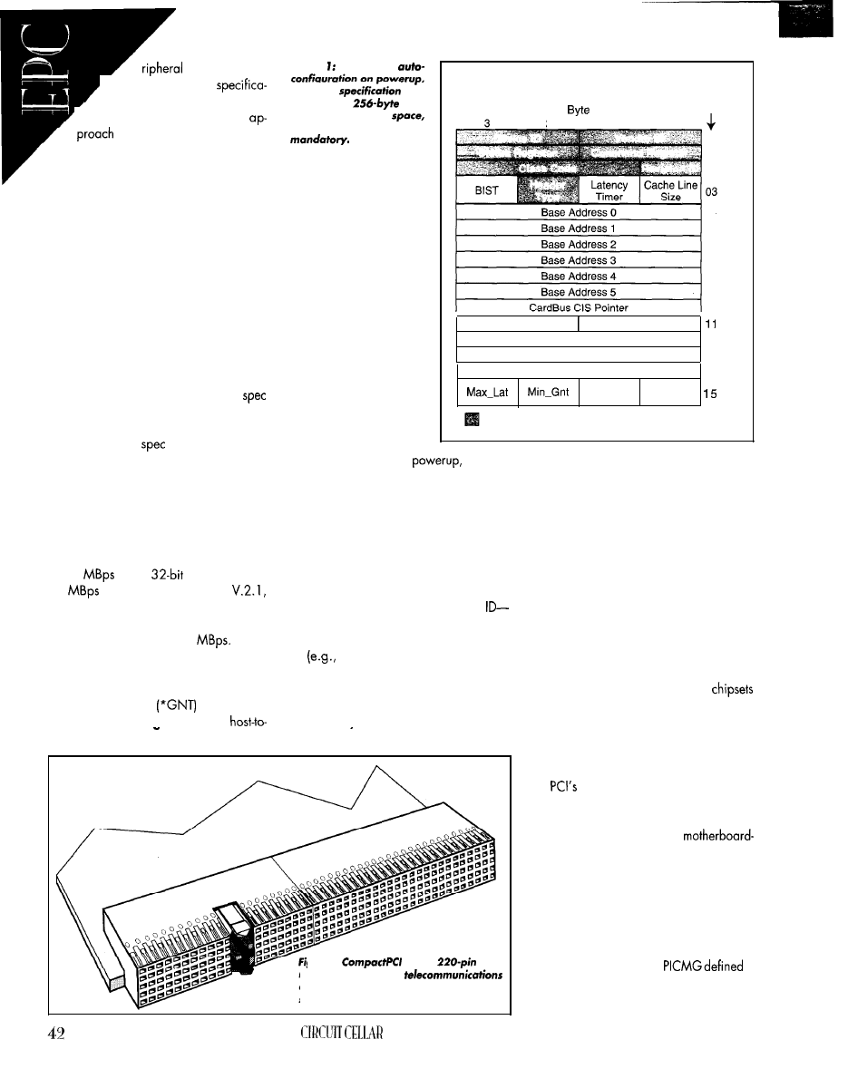
’
Component In-
terconnect (PCI)
,
tion in June 1992.
PCI uses a workstation
for interfacing a Local-bus
device to the processor bus. It combines
the processor’s level-2 cache controller
with a bridge that acts as an interface
between the processor, main memory, and
the Local bus.
With the Local-bus interface indepen-
dent of the processor’s bus, the Local bus
becomes processor independent. When a
new processor becomes available, only
the bridge chip needs replacing.
The workstation approach also enables
the processor to access information from its
cache, while the cache controller allows a
PCI-bus master access to main memory or
other PCI devices on the Local bus.
Intel thought it best to make the PCI
an open standard. They helped form the
PCI Special Interest Group, which defined
the standard PCI
as well as revisions
for supporting 64-bit extensions and 3.3-V
technology. Let’s look at some of the other
advantages PCI offers over VL bus.
On the PCI bus, all read and write
operations are burst transfers lasting as
long as the target can receive or send data.
At 33 MHz, a maximum data transfer rate
is 132
using
transfers and
264
using 64-bit transfers. PCI
released in 1995, supported 66-MHz bus
speeds, doubling the maximum data trans-
fer rate to a whopping 528
PCI bridge chip.
Multiple bus masters are supported un-
der PCI, with each master being connected
to an arbiter via a pair of bus request
(*REQ) and grant
signals. The
arbiter is usually integrated into the
Figure To support
the Intel
rec-
ommends a
con-
figuration register
the first 64 registers being
Arbitration is allowed
while the current bus mas-
ter performs a data trans-
fer by removing *GNT
from this master and issu-
ing it to the next owner of
the bus. This hidden arbi-
tration doesn’t waste bus
time in arbitrating cycles.
04
05
06
07
08
09
10
Subsystem ID
Subsystem Vendor ID
Expansion ROM Base Address
12
Reserved
13
14
Interrupt
Line
Required Configuration Registers
Unlike VL bus, PCI
clearly defines configura-
tion address space to sup-
port autodetection and
configuration of PCI pe-
ripheral cards. Configura-
tion software detects PCI
devices on the bus at
typically
through PCI BIOS calls, and then accesses
the configuration address space of each
device to determine its requirements and to
Reserved
Interrupt
Pin
Figure 1 illustrates a typical PCI-device
configuration header.
Unlike other bus architectures, PCI
doesn’t use terminating resistors at the end
of the bus, so the signal wavefront can
reflect back down the bus. Weaker output
drivers drive the signal line to half the
desired logic state. The resulting signal
wave is doubled when reflected back,
registering a logic high at each device
along the way.
Doubleword
Number
(in Decimal)
2
1
0
00
01
02
assign it unique memory and I/O regions.
A PCI device’s configuration address
space consists of a base set of 64 registers
subdivided into several groups:
l
Vendor ID, Device ID, and Revision
aid in vendor identification
l
Class Code-identifies its basic function
mass storage, network, video,
etc.)
configuration header
l
Command and Status-control how it
responds to and performs PCI accesses
. Header Type-describes the format of its
gure
2:
uses a
con-
nector designed for
applications. Additional grounding and
shielding helps ensure signal integrity.
This reflective wave-switching technol-
ogy reduces driver size as well as surge
current, but it makes capacitive loading on
the bus an important concern. PCI
can drive up to 10 loads, and with compo-
nents, connectors, and cards each consid-
ered one load, this equates to three slots.
I N D U S T R I A L C O N C E R N S
increased performance capabili-
ties drew the attention of industrial-PC manu-
facturers. However, passive-backplane ar-
chitectures are favored over
based designs in industrial applications
mainly due to improved reliability and
ease of component replacement.
To address this, the PCI Industrial Com-
puter Manufacturers Group (PICMG) con-
sortium was formed in 1994 by I-Bus,
Teknor Industrial Computers, Texas Micro,
and Trenton Technology.
a
passive-backplane PCI standard where a
PCI connector was added to the back of
INK APRIL 1997
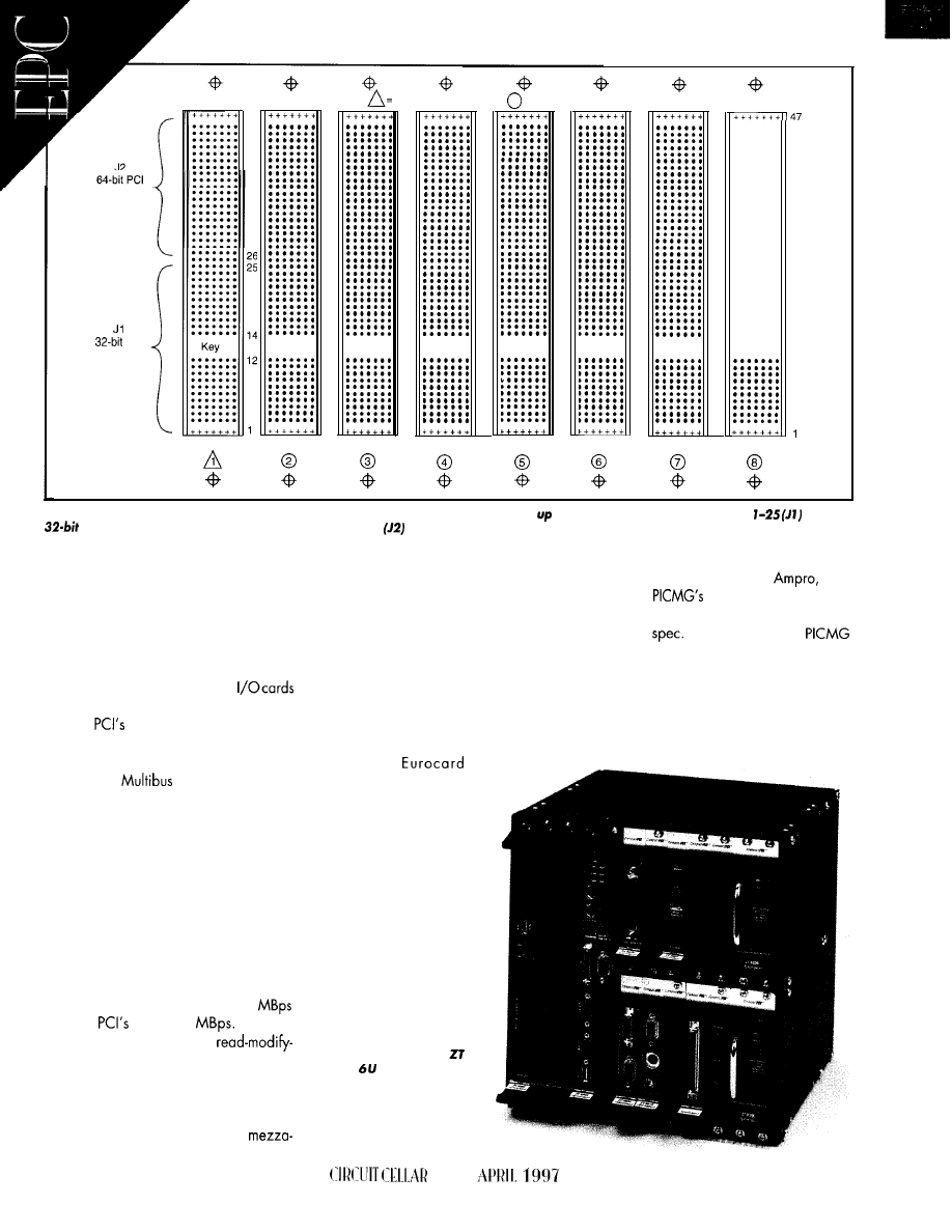
Extension
55 Signals
PCI
125 Signals
z a b c d e f
4i
System Slot
= Peripheral Slot
. . . . . . .
. . . . . . .
. . . . . . .
. . . . . . .
. . . . . . .
. . . . . . .
. . . . . . .
. . . . . . .
. . . . . . .
. . . . . . .
. . . . . . .
. . . . . . .
. . . . . . .
. . . . . . .
. . . . . . .
. . . . . . .
. . . . . . .
. . . . . . .
. . . . . . .
. . . . . . .
. . . . . . .
. . . . . . .
. . . . . . .
. . . . . . .
. . . . . . .
. . . . . . .
. . . . . . .
. . . . . . .
. . . . . . .
. . . . . . .
. . . . . . .
. . . . . . .
Figure 3: A CompactPCl backplane
consists of one system slot located at either end and to seven peripheral slots. pin rows
support
PCI and
the keying mechanism, while rows 2647
support
M-bit PCI extensions, user-defined signals, and pins reserved for future
expansion.
passive-backplane ISA boards to maintain
backwards compatibility.
Thisapproach solved some maintenance
issues, but it didn’t solve connector reliabil-
ity or vibration concerns. Also, industrial
PCs typically need to support six or more
slotstoaccommodatespecialized
and standard peripherals-this was well
beyond
four-slot limitation. Repeater
cards with PCI bridges support additional
slots but at a performance penalty.
nine standard to its STD 32 Pentium proces-
Teknor, Pro-log, I-Bus, and
and
sor boards. The form factor of existing PCI
laterwith
blessing, Ziatech worked
mezzaninecards like the PMC is incompat-
with other companies on the first draft of
ible with the STD 32 form factor, and as I
this new
It was presented to
mentioned, the cards aren’t stackable.
in early 1995 and became CompactPCI.
VME and
manufacturers also
adopted PCI support through a defined
mezzanine approach called PCI Mezza-
nine Card (PMC). These cards mount near
the front of VME boards using a pin and
socket connection. The I/O signals pass
through the front panel.
From this development effort emerged
the concept of a well-defined and open
passive-backplane PCI standard that uses
commercially available PCI chipsets, sup-
ports more than four slots,
a d o p t s a
format and packaging
options, and allows for
future hot-swap capabil-
ity of peripheral cards.
After meeting with
other industrial computer
manufacturers including
Unfortunately, PMC modulesdon’tstack,
and their form factor limits the number of
modules that can be mounted on a VME
board to two. linking PMC modules over
the VME backplane introduces timing diffi-
culties since
VME
transfers data at40
whereas
rate is 132
Also, PCI
can’t directly support VME
write transactions.
CompactPCl EMERGES
In 1994, Ziatech Corporation was in-
vestigating implementing PCI as a
Photo 1: The Ziotech
55 10
C o m p a c t P C l
Pentium board supports
up to 14 CompactPCl pe-
r i p h e r a l c a r d s o n t w o
s e p a r a t e C o m p a c t P C I
buses without bridging.
44
INK
Now, let’s take a close look at how
CompactPCI overcame the limitations of
both desktop and industrial PCI implemen-
tations.
NUTS AND BOLTS
CompactPCl is an implementation of
Intel PCI electrical signals on a
format with a rugged gas-tight
connector.
As shown in Figure 2, the
chosen connector is a shielded,
pitch,
connector currently manufac-
tured by AMP, Framatone, and
and
designed for telecommunication and
backplane applications.
Additional features including high
ground-to-signal ratio, shielding for
protection, a positive keying mecha-
nism, and a rear pin option for
backplane I/O connection.
defines a 7-column x
pin array divided into two groups.
Pins l-25 on one connector support
PCI and connector keying, while pins 26-
47 on a second connector support 64-bit
PCI transfers with some pins reserved for
future enhancements. The Functional subdi-
vision of these pins is shown in Figure 3.
The CompactPCl backplane consists of
one system slot that provides arbitration,
clock distribution, and reset functions for
other adapters. And, it has up to seven
peripheral slots that can accommodate
simple adapters, intelligent slaves, or
bus masters. Note that the system slot can
be located at either end of the backplane.
The greatest challenge
faced was overcoming
three periph-
eral-slot limitation.
The connector chosen for CompactPCl
cards was a key factor towards increasing
slot count. Remember, PCI
can
drive 10 capacitive loads. Desktop PCI
card-edge connectors typically have a ca-
pacitive load of 12
whereas the 2-mm
hard metric connector chosen for
CompactPCl has a capacitive load of 2
per pin.
PCI signals were carefully mapped onto
the 2-mm connector’s pins to take advan-
tage of its extra ground pins and column
coupling. And,
stub terminating resis-
tors were added to all bused PCI signals on
each adapter board to distribute termina-
tion and minimize
A technical
headed by
Ziatech cooperated with AMP Interconnec-
tion Systems to conduct an extensive simu-
lation of Intel PCI signaling through this
connector, across a passive backplane,
and onto peripheral cards using commer-
cially available PCI chipsets. Lightly,
mod-
erately, and fully loaded eight-slot
2
Channel Digital Oscilloscope
100
max single shot rate
samples per channel
Advanced Triggering
Only 9
and 6.3” x 3.75” x 1.25
Small, Lightweight, and Portable
Parallel Port interface to Laptop
0
Advanced Math, TV Line Trigger, and FFT Spectrum Analyzer options
$499 you get the model DSO-2102 Oscilloscope, Probes, Interface Cable,
Adapter, and Windows and DOS Software.
l
up
to
Samples/Channel
l
FFT and Spectrum Analyzer
DSO-28264 (1
64k)
DSO-28464
$3299
All prices
Probes and Sdftware
40 to 160 channels
Variable Threshold
16 Level Triggering
l
up to 500 MHz
l
8 External Clocks
l
up to
40CH)
$1350
80CH)
$2000
40CH)
$1900
80CH)
$2800
LA451 60-l 28K
$7000
All prices include Pods and Software
Call for information on our
100
Pattern Generator option
Link Instruments
369 Passaic Ave
l
Suite 100
l
Fairfield, NJ 07004
l
Fax (201) BOB-8786
Web:
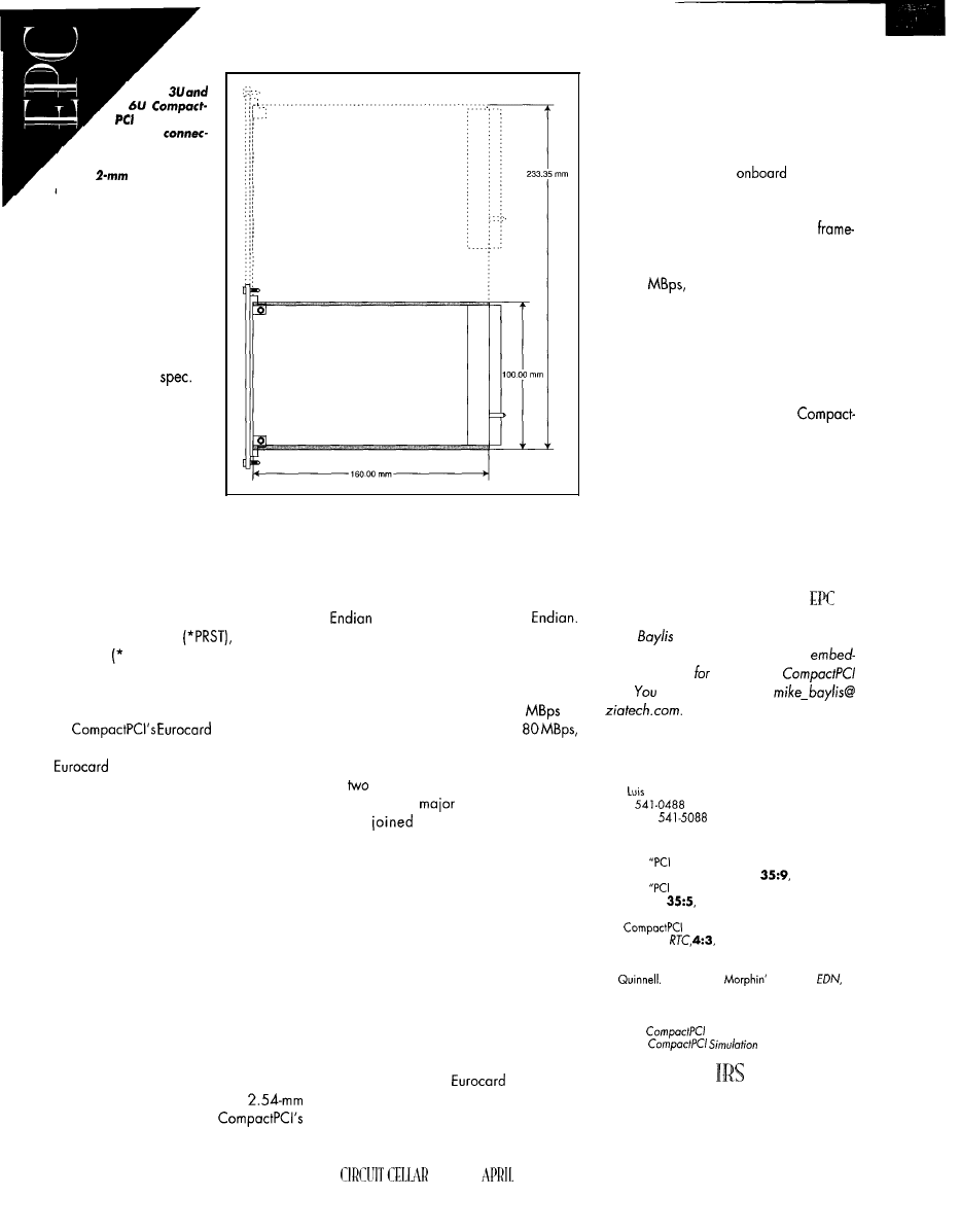
Figure 4:
B o t h
boards have
the same
tor, with 6U boards
supporting an addi-
tional
connector for
user-defined signals.
backplanes were modeled
to determine the best-,
nominal-, and worst-case
buffer technologies al-
lowed by the PCI
In the fully loaded
backplane model using the
weakest drivers, all PCI
signals’worst-case settling
times fell within acceptable
limits. In the lightly loaded
backplane model using the
strongest drivers, the unloaded connectors
presented a long unterminated stub that
was easily addressed by adding diode
termination at the far end of the trace.
Some additional signals defined by
CompactPCI to enhance system operation
are push-button reset
power-sup-
ply status DEG, * FAL), system slot identi-
fication (*SYSEN), and legacy IDE inter-
rupt support. However, these additional
signals don’t affect the existing PCI signals.
format enables
users to take advantage of already existing
enclosures designed for VME
systems. And, manufacturers can design
core 3U and optional 6U format boards
that will coexist in the same system as
shown in Photo 1. Both form factors have
the same 2-mm connector, with the 6U
format supporting an area for a user-de-
fined second connector as you see in
Figure 4.
You may have noted similarities be-
tween CompactPCl and VME in both per-
formance and packaging, and you’re prob-
ably wondering whether the two bus struc-
tures will compete or coexist.
So, let’s discuss their differences.
CompactPCl OR VME?
Although both bus structures support 3U
and 6U formats, VME uses a
connector scheme versus
2-mm connector. The two buses use entirely
different data-transfer methods. And, VME
has an asynchronous scheme, while
CompactPCl uses a synchronous clock.
As well, VME and CompactPCl perform
byte transactions differently. VME uses Big
and CompactPCI, Little
Also, VME lacks the plug-and-play capa-
bilities found in PCI systems.
From a performance standpoint,
CompactPCl looks like the winner, support-
ing data transfers up to 264
at
64 bits.
By
contrast,
VME supports
using VME64 extensions.
Despite these differences, it’s likely that
the
buses won’tcompete head to head.
Indeed, many
VME manufacturers
have
PICMG, are endorsing
CompactPCI, and are announcing prod-
ucts. One VME manufacturer, Force Com-
puters, has developed a 6U CompactPCl
card implementing CompactPCl signals on
one connector and VME64 extension sig-
nals on another.
POTENTIAL APPLICATIONS
So, where does this new standard fit in?
Early inquiries into CompactPCl have
come from companies involved in telecom-
munications applications.
Besides its extremely high bandwidth,
CompactPCl offers
packaging
and a connector widely used by the tele-
communications industry for both its modu-
larity and reliability. The additional con-
nector on 6U cards can bridge to other
buses such as
ISA, VME,
and STD 32.
Vision applications are also well-suited
to CompactPCI. In the past, ISA-based
frame-grabber boards were expensive
because they needed
processors,
large amounts of RAM, and special soft-
ware to capture and process images.
Since a CompactPCI bus-master
grabber board can grab images and trans-
fer them to the CPU board’s main memory
at 132
it no longer needs its own
buffer memory. The host CPU can then use
less expensive desktop image-processing
libraries.
The avionics industry can also take
advantage of CompactPCl’s performance
and small, rugged form factor. Given the
space limitationsofaircraft, a 3U
PCI system is an excellent choice over a 6U
VME. And, it offers better performance.
CompactPCI has taken the performance
capabilities of Intel
PCI,
overcome its slot
limitations, and packaged it into a small,
rugged form factorwell-suited for industrial
applications requiring high performance.
It’s also an open, well-defined, and in-
creasingly accepted standard among in-
dustrial computer manufacturers.
Mike
is an applications engineer for
Ziatech, a manufacturer of small
dedcomputers
STD
32 and
Bus.
may reach him at
SOURCES
CompactPCl
Ziatech Corp.
1050 Southwood Dr.
San
Obispo, CA 93401
(805)
Fax: (805)
REFERENCES
J. Child.
Becomes Entrenched in Embedded
Boards,” Computer Design,
1996.
J. Child.
and VME Dare to Shore,”
C o m p u t e r
Design,
1996.
R. Davidson and P. Nash. “Early Adopters of New 3U
Standard Embrace Its Small Size and
Speed,”
1996.
PCI Special Interest Group,
PC/ Fundamentals, Intel,
1993.
R.
“The Mighty
PCI Bus,”
9,
1996.
T. Shonley and D. Anderson, PC/ System Architecture,
3rd ed., Mindshore, Inc., 1995.
Ziatech,
Short Form Specification, 1996.
Ziotech,
Overview, 1996.
4 10 Very Useful
41
1
Moderately Useful
4
12
Not Useful
46
INK
1997

Want a robot that vacuums your house while you’re not home to be bothered?
Sounds great, right? Frank combines boards
from
and
with a three-level
program to bring that fantasy closer to reality.
hen started this project over five
years ago, had three primary goals.
wanted real-world (not lab), hands-on ex-
perience with an autonomous mobile robot.
also wanted to evaluate various types
of mechanical parts, electronic systems,
sensors, and software algorithms. And,
wanted to promote the concept of autono-
mous robots as practical devices rather
than experimental curiosities.
Engineering projects need well-defined
specifications to guide development deci-
sions. decided that a worthwhile, but
seemingly not-too-difficult, robotics
to perform household vacuum cleaning.
This robot wouldn’t vacuum randomly
like a swimming-pool cleaner. Rather, it
would automatically map out the house,
plan vacuuming paths, and proceed to
clean on a regular schedule.
shown in Photo 1, was de-
signed as a home appliance rather than a
robot. As such, it needed to meet the
average consumer’s expectations for reli-
ability, ease of use, and safety.
48
It had to operate properly for many
maining within my modest budget. Rather
months without repair or
Users
than buying surplus
then building
shouldn’t need backgrounds in mechanics,
a robot, designed the robot first and then
electronics, or software.
The
device
shouldn’t
intended to buy, modify, or build exactly
damage (or be damaged by) household
what I needed.
objects. And most critically, it had to
Inevitably,
I
compromised. Often, the
ate safely around pets and small children.
time and cost of using or modifying an
I wanted a no-compro-
mises robot-one that
would come as close as
possible to a
ready product while
Photo I: In this rear view of
(lower shell re-
moved), you can see
sensor ring and lower part
of
canister. The
electronics bay with its cir-
cuit breakers and switches
is mounted at the rear of
the chassis. One of the main
drive wheels and both rear
castors can also be seen.
This picture is about two
years old. The latest con-
figuration
CELLAR INK
1997
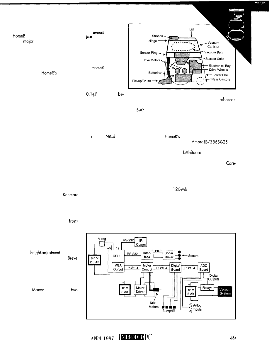
t h e - s h e l f p r o d u c t w e r e s u b s t a n t i a l l y l e s s
than designing and building parts.
Since its inception,
has under-
gone two
design revisions in both its
mechanical and electronic configurations.
About the only original parts are the drive
motors and the wheels.
M E C H A N I C A L A N D E L E C T R I C A L
Figure 1 shows
mechanical
layout. The most visually notable feature is
the large main-drive wheels, which give
good traction on uneven surfaces and a
light footprint on carpets. Two smaller
costoring wheels are used at the robot’s
rear corners.
The main chassis was designed to be
modular and look like die-molded plastic.
It’s actually made of thin marine-grade
plywood, which approximates the weight,
strength, and stiffness of molded plastic
and permits easy modification.
The lower shell is constructed as a
fiberglass-foam sandwich composite. The
middle sensorring is a complex structure
made from fiberglass-balsa and-foam sand-
wiches, plywood, and acrylic plastic.
The vacuum canister is built from ply-
wood, fiberglass, and foam. The lid uses a
fiberglass-balsa sandwich base with a cus-
tom-molded Kevlar top.
The canister was designed around a
standard filter bag from a large
canister vacuum. The bag is easily re-
placed by lifting up the front-hinged top lid.
The vacuum system combines two suc-
tion motors derived from Black and Decker
12-V car-vats. The retractable,
mounted pick-up unit (with a rotary brush)
is a heavily modified Black and Decker
battery-powered floor vacuum. The pick-
up/brush unit is electrically retractable (with
a mechanical up-lock mechanism) and has
an automatic
feature.
The two main drive motors are
servo-type gear motors (85: 1 reduction).
They nominally use about 2 A of power at
12 V, but during startup,
they
can consume
up to 8 A.
The suction retract/extend motors are
two identical
motors with a
stage 15:
1
belt reduction and a combined
peakoperating currentof less than 2 A. The
two suction motors are the major power
draw, using about 6 A at 12 V with no load
and more than 10 A under some condi-
tions. The beater-brush motor draws -2-
3 A, depending on the floor surface.
Figure I:
The vacuum
cleaner is integmted into
the
design, not
added on.
only has DC
brush-type motors. To
m i n i m i z e e l e c t r i c a l
noise, the motor cases
a r e g r o u n d e d w i t h
capacitors
tween the brush connectors and the case.
Three battery systems power the motors
and the electronics. A 12-V,
battery
powers only the suction and brush motors.
Another 12-V, S-Ah battery powers the
wheel drive motors, and a 9.6-V, 2.5Ah
battery powers the electronics.
chose
battery packs for their
high power density, low internal resis-
tance, and deep discharge capability. The
batteries are wired independently, using
optocouplers and relays for complete isola-
tion from one another. Each battery pack is
protected with an internal fuse, and the
electrical systems contain an additional
seven circuit breakers.
For safety, two nonsynchronized strobe
lights mounted inside the canister lid are
activated when the wheel motors are en-
abled. Ribbon cables integrated into the lid
hinge provide power and data wires for
the lid-mounted electronics.
The electronics and the motor circuits
power on via two push buttons, accessible
through a movable
panel on the
back
of the
lower shell. In an emergency, the
be powered off
by
simply
hitting the panel.
The original projected weight of the
robot was 25 Ibs., but it’s now over 40 Ibs.
E L E C T R O N I C S A N D S E N S O R S
Figure 2 shows a basic diagram of
electronics. The primary proces-
sor board is an
with
4 MB of RAM. designed the basic robot
around the
form-factor because
it was the smallest ‘x86 processor board
available at the time. (The smaller
Module hadn’t yet been announced.) A
color VGA card piggybacked onto the
main board enables a video monitor to be
connected.
A
2.5” hard drive connected to
the IDE port is used for booting, program
storage, and data logging. If necessary, a
keyboard and/or an external floppy drive
can be connected for data transfer and
debugging code. Typically, though, large
code is done on another computer and
uploaded through the parallel printer port.
Sensors
Figure
2:
Both the PC/l 04 bus and the RS-232 ports are used for data acquisition and control.
Three battery systems isolate the electronics, motor driver, and vacuum-system power.
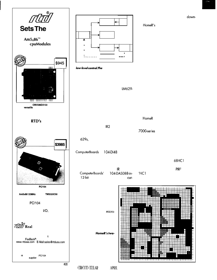
Pace
133 MHz
PC/l 04
Exceed
Pentium-75 Performance
Our
and ISA Bus
product lines feature
A n a l o g a n d D i g i t a l
CPU, DSP,
Shared Memory, SVGA, PCMCIA,
CAN Bus and Intelligent GPS
Time Devices USA
200
Innovation Boulevard
l
P.O. Box 906
State College, PA 16804-0906 USA
Tel: 1 (614) 234-8087
l
Fax: (814) 234-5218
1 (814) 235-l 260
l
RTD Europa RTD Scandinavia
Budapest, Hungary
Helsinki, Finland
Fax: 36-l-326-6737
Fax: 356-9-346-4539
RTD a founder of the
Consortium and the
world’s leading
of intelligent ISA DAS interfaces.
The
offers
embedded functionality
Embedded PC and DSP
Drive
Intelligent
Data Acquisition and
Control Board
The IDAC5210 with
extension bus,
500 KHz analog and digital front-end
is powered by on-board
CPU and
DSP
50
Deliberative
User
Level
Input
Operations
Status
Sensor
Control
Data
Level
Actions
Status
Reactive
Motor
Level
Control
Outside World
Figure
3:
The Reactive level performs simple,
Controlkvelestablishes
the priorities for the Reactive level, and the
Deliberative level does the general planning.
All levels can access sensor data.
The CPU connects through the PC/l 04
bus to a Mesa Electronics 4127
based servo-motor controller board that’s
used only for the main drive motors. The
motors use Hewlett-Packard HEDS-5500
quadrature optical motor encoders (1440
cpr), which feed back into the controller.
The motor-controller board connects
through optocouplers to the motor encod-
ers and a custom-built NMOS H-bridge
PWM motor driver with
1 1 OMOS driver
chips. Thus, once the CPU determines each
motor’s trajectory, it sets register values in
the
starts the motors, and is then free
to perform other tasks.
put
analog board senses motor
rents and battery voltages. It
also has 4 digital outputs to
control the vacuum motors
through relaysand the pickup
retraction/extension system.
Also connected on the PC/l 04 bus is a
PC
48-pin digi-
tal input board. It’s based on 74LS logic
chips but uses standard 8255 data-transfer
protocols. The digital inputs sense the state
of the 22 microswitches and 8 sensors.
PC
pickup/brush is in the up-lock or
floating position.
bumper senses and absorbs
collisions. The lower shell is shock-mounted
to the chassis and has eight microswitches
to sense collisions from any direction.
The sensor ring and vacuum canister
are also shock-mounted to the chassis, with
eight more microswitches detecting displace
ment in any direction. The front pick-up/
brush unit has two wrap-around bumpers
that can activate two more microswitches.
Eight modulated-light infrared sensors
are mounted around the sensor ring. The
sensor pairs each use an LM567 tone
decoder to modulate outgoing light and
detect reflected light.
The IR sensing uses a triangular beam
path to indicate when an object is within
-4”. No attempt is made to determine
analog distance using the reflected light
intensity. The output of each ‘567 is a
binary detect/nodetect sent to the digital
input board.
can have up to 26 sonar dis-
tance detectors, although only 8 are in use
currently. A total of 24 square Polaroid
transducers are mounted in
the sensor ring. Two round transducers are
also mounted to the front of the lower shell.
requests distance readings as needed.
While the sensors are intended prima-
rily for obstacle detection, they have lim-
ited mapping capability. The CPU is con-
nected via RS-232 to a Processing Innova-
tions Robotics Research
1 board
that communicates to a sonar driving/
sensing board over their
bus. The
1 handles all sonar control. The CPU
T h e e x t e n d e r / r e t r a c t o r
motors have no encoders. In-
stead, they use four
switches to sense whether the
F i g u r e 4 : I n
dimensional world,
floor space
is broken up into equal-sized
cells. Each cell is assigned a
value that indicates whether
the floor space is empty, has
some obstruction, or is off
limits. The shading represents
the different cell values.
INK
1997
Table Some of these Control-level actions
might be generated by
operation “Position-at-second-door-on-lefi.
The normal actions are designed to
the task, assuming no problems. Contingency
actions are available if problems occur.
User communication to the robot is via
an infrared hand-held remotecontrol key-
pad. The receiver module and electronics
(based on the Forte Infrared Communica-
tor) located inside the canister lid connect
to an RS-232 port on the CPU board.
Communication from the robot is through a
vocabulary of distinctive
beeps.
While the motors are driven directly
from 12-V batteries, most of the electronics
use 5-V power from two 3-A
An IPS
2-W DC-to-DC voltage converter generates
the 12 V for the analog input board.
Almost all the electronics are mounted
in a single bay at the back. It also contains
the powerconversion electronics, the cir-
cuit breakers, and two small cooling fans.
This bay removes as a single unit to facili-
tate circuit-board development and trouble
shooting.
SOFTWARE LANGUAGE AND OS
The software is written in Borland C++
and uses
robot programming func-
tions.
is a set of high-level C++
functions(suchosMoveBase,GetSonar,
etc.) that give basic function control and
monitoring without having to deal with the
low-level characteristics of the robot’s hard-
ware.
The software currently runs under
DOS V.6.2, which is widely available,
predictable, and low cost. However, DOS
has none of the multitasking capabilities
that would suit this real-time application.
Concurrent operation is handled by
careful software design and a lot of polling.
The lack of multitasking is somewhat allevi-
ated by independent processors for basic
motor control and sonar ranging, but the
OS is clearly a weak point in the software.
SOFTWARE ARCHITECTURE
overall program structure is a
variation on what’s rapidly becoming the
standard robotics Al software architecture.
As shown in Figure 3, this multilevel system
comprises Deliberative, Control, and Reac-
tive levels.
at second-door-on-left”
Normal Actions
align-parallel-left-wall
follow-left-wall
move-forward-medium-speed
follow-left-wall
center-to-left-opening
rotate-left-90
Contingency Actions
avoid-obstacle
recover-bumper-hit
search-for-opening-left
end-of-corridor
request-fail-replan
At the top, the Deliberative level decides
the robot’s goals. It maintains a map and
has access to path planners to determine
how to move through the robot’s world.
Using the system clock/calendar, the
robot’s current location and action, and
possibly inputs from the user, the software
determines the robot’s main operating
mode. Based on the mode, a set of ordered
operations are defined and sent to the
Control level.
The Control level mediates between the
smart Deliberative and dumb Reactive lev-
els. After receiving the operations list, this
level determines the robotaction sequence.
For each action, the program uses cer-
tain sensor inputs to create a prioritized list
of skills, each with associated parameters.
An action’s skill list is submitted to the
Reactive level. While the action is pro-
cessed, the Control level monitors both the
sensors and the Reactive-level operation to
determine when to submit the next action.
The Reactive level simply does what it’s
told. It continually reevaluates the priori-
tized skill list. Based on certain sensor
inputs, it controls the robot’s motors and/or
the sound output.
All three levels operate concurrently,
but their expected response times vary
greatly. The Reactive level performs its I/O
responses within milliseconds, so the robot
can react rapidly to sensor changes (e.g.,
a bumper hit). To generate smooth transi-
tions between activities, the Control level
requires typical response times of a few
tenths of a second.
Most of the Deliberative level’s
and timeconsuming activities (e.g., plan-
ning) occur while the robot is inactive. But,
if the robot has to deal with an unexpected
problem or plan change, it may remain
motionless while it “thinks.”
In this system, control between levels is
downward and only to the next level below.
ISA slots
51
The
motherboard
combines quality and
affordability with an industrial
design to meet your needs.
Seven full length ISA slots
ensure expandability for the
cards that you use.
Our engineering staff will
gladly discuss custom
motherboard designs. FCC
& UL certified systems are
also available.
l
Six full length
ISA, One
shared
slot
l
Intel, AMD SGS-Thomson
486 CPU support
l
VIA
l
Up to 64MB RAM, 256KB cache
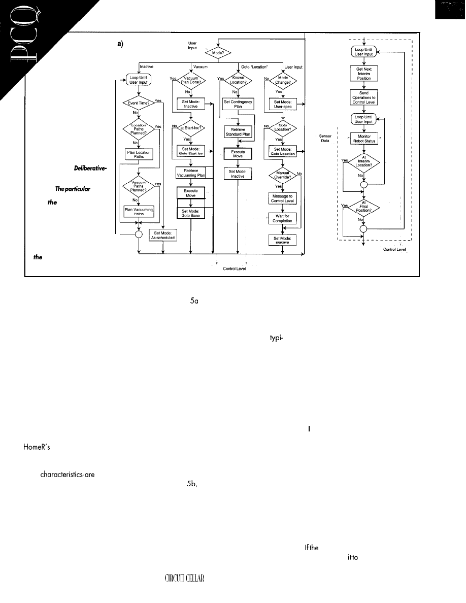
Figure 5a: The
l e v e l p r o g r a m a l w a y s o p -
erates in one of several
modes.
mode
depends on
several factors,
and
robot can se/f-
switch between modes.
b: In the execute-move box,
the robot sends movement
operations to the Control
level and waits until the
move is completed. The
Control level can signal if
robot is unable to com-
plete the action.
b) I--
All levels can access sensor data, but user
input is only into the Deliberative level. Also,
only the Reactive level controls the robot’s
actions.
The top two levels each receive status
signals from the next lower level. However,
as indicated in Figure 3, the control loops
are closed primarily through the robot’s
environment (as interpreted by the sensors).
Each level responds to what happens, and
not just what’s supposed to happen.
A key software component is a map of
the robot’s working environment. Using the
map, the program can search for and
evaluate optimum paths for vacuuming or
between two points.
This 2D topological map subdivides
environment into 4” cells. Each
cell is assigned a value indicating if the
floor space is occupied or free, although
other
also encoded.
In the map section shown in Figure 4,
the shading indicates each cell’s assigned
value. Currently, the map is manually en-
tered and maintained.
As you’ll see, each of the three levels
performs specific functions, but it is the
interaction between the levels (and the
environment) that ultimately determines how
well HomeR performs.
52
DELIBERATIVE LEVEL
Figure
details the Deliberative-level
operation. Within each operating mode,
the robot can take several actions, includ-
ing self-switching to another mode.
In the inactive mode, the robot is
callywaiting for a scheduled action time or
for remote-control input. During this time,
the robot can also do path planning or
other time-consuming background tasks.
In the vacuum mode, HomeR verifies its
starting location and whether it has a path
plan. It then executes the movements neces-
sary to vacuum the accessible floor space.
In the goto-location mode, it uses the
internal map to navigate between locations.
If the start and end positions are standard,
the program can call up a predefined plan.
Otherwise, it may create a contingency
plan.
During theexecute-move processshown
in Figure
the Deliberative level continu-
ally breaks the robot’s path into subpaths,
which are then sent to the Control level.
While the robot moves, the Deliberative
level monitors both the robot’s position and
the Control-level operation. If a problem
occurs (e.g., the robot is “lost” or batteries
are low), the Deliberative level may acti-
vate an appropriate contingency plan.
INK APRIL 1997
The calibrate mode (not shown) uses the
remote control and sound output to check
whether all external sensors are operating
correctly.
Of course, HomeR is ultimately con-
trolled by a human with a remote control.
The user can then change the mode or goal
location, or manually override to directly
control the robot’s movement.
Note, however, that regardless of the
remote command, the Control level may
prevent the robot from following direct
orders (e.g., ramming into a wall) if it
would damage the robot. While this doesn’t
follow Dr. Asimov’s Second Law of Robot-
ics, don’t want HomeR to damage itself
because of an inept human.
Consider this scenario. HomeR is wait-
ing at its home location, which will eventu-
ally include an automatic charger. It’s pro-
grammed to begin vacuuming a certain
room at a specified time.
At that time, HomeR wakes up and goes
into vacuuming mode. If it’s not at the start
location, it moves there and reverts to
vacuuming mode. When the task is done,
it switches to goto-base mode and returns
home.
robot is in the middleofvacuuming
and the userwants
return to the charger,
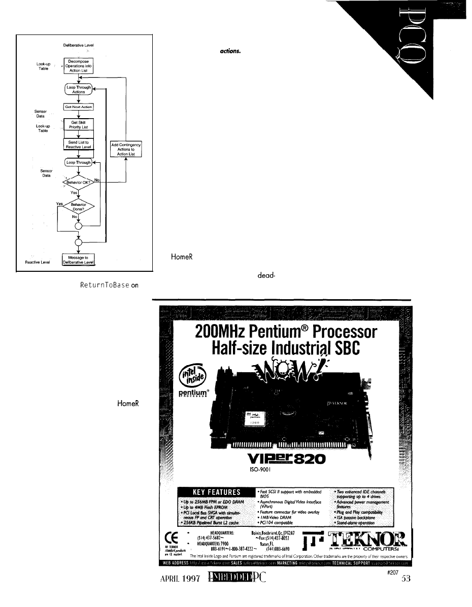
theusersimplyenters
the remote control. Since the robot was
unexpectedly interrupted, it must stop and
custom plan a path back to the charger.
CONTROL LEVEL
The Control level takes an ordered set of
operations from the Deliberative level and
converts them into prioritized skill sets for
the Reactive level. In practice, this task is
much easier to state than implement.
As Figure 6 details, the operations sent
from the Deliberative level are first decom-
posed into an action list. Currently,
uses a look-up table approach where a
given operation causes a certain set of
actions (and contingency actions) to be
retrieved.
Some operations map one-to-one to an
action (e.g., Immediate-Stop), but in
general, each operation generates mul-
tiple actions and contingency actions. Table
1 shows how a complex operation might
expand to a sequence of normal and
contingency actions.
As the program loops through each
action, it uses another look-up table to
generate a priority list of Reactive-level
skills. This listcontainsoneor more primary
skills for accomplishing the task as well as
some contingency skills.
Figure 6: In Control-level program flow,
Deliberative-level operations are broken
down into a series of
Each action
is then converted into a prioritized
skill
list
that’s sent to the Reactive level. If a prob-
lem occurs, the Control level may add its
own actions to the fist to attempt to re-
solve the problem.
Using a proprietary method, sensor
data defines the specific parameters for
each skill in the priority list. The finished
list is sent to the Reactive level for
processing.
While the Reactive-level skills are
running, the actual results are continu-
ally compared with intended actions.
When an action completes, it is re-
moved from the action list, and the code
loops to process the next action.
Suppose the Deliberative level wants
the robot to go down a hallway and
position at the second door on the left.
The Control level decomposes the op-
eration as shown in Table 1.
first aligns itself with the
corridor and follows the left wall to the
first door, where it switches to
reckoning until it reacquires the wall.
When the robot reaches
the second door, it centers
with reference to the doorway
and turns left.
The program repeatedly checks
that the active skill is a primary skill. If a
contingency skill is activated or the sensors
detect a problem, the Control level may
call
on an interim contingency action.
It’s entirely possible for the robot to
request a new contingency action while it’s
processing an existing contingency. For
example, if it sees an obstacle in the
hallway, it must first get around it. How-
ever, if an unexpected bumper hit occurs
while avoiding the obstacle, another con-
tingency action may be necessary before
continuing the obstacle avoidance.
Generally, the Control level attempts to
complete the requested operations. How-
ever, as a last resort (e.g., the robot cannot
get around the obstacle), the Control level
requests a new plan from the Deliberative
level.
REACTIVE LEVEL
This level contains a library of skill
functions, each of which evaluates some
TEKNOR,
certified, designs and manufactures the
world’s most advanced and reliable industrial SBC and systems.
Call TEKNOR todav at l-800-387-4222.
CANADIAN
616 Cure
PI:
I-800-354-4223
U.S.
Glades Road. Boo
33434
Tel: (561)
fax:
I N D U S T R I A L
I N C .
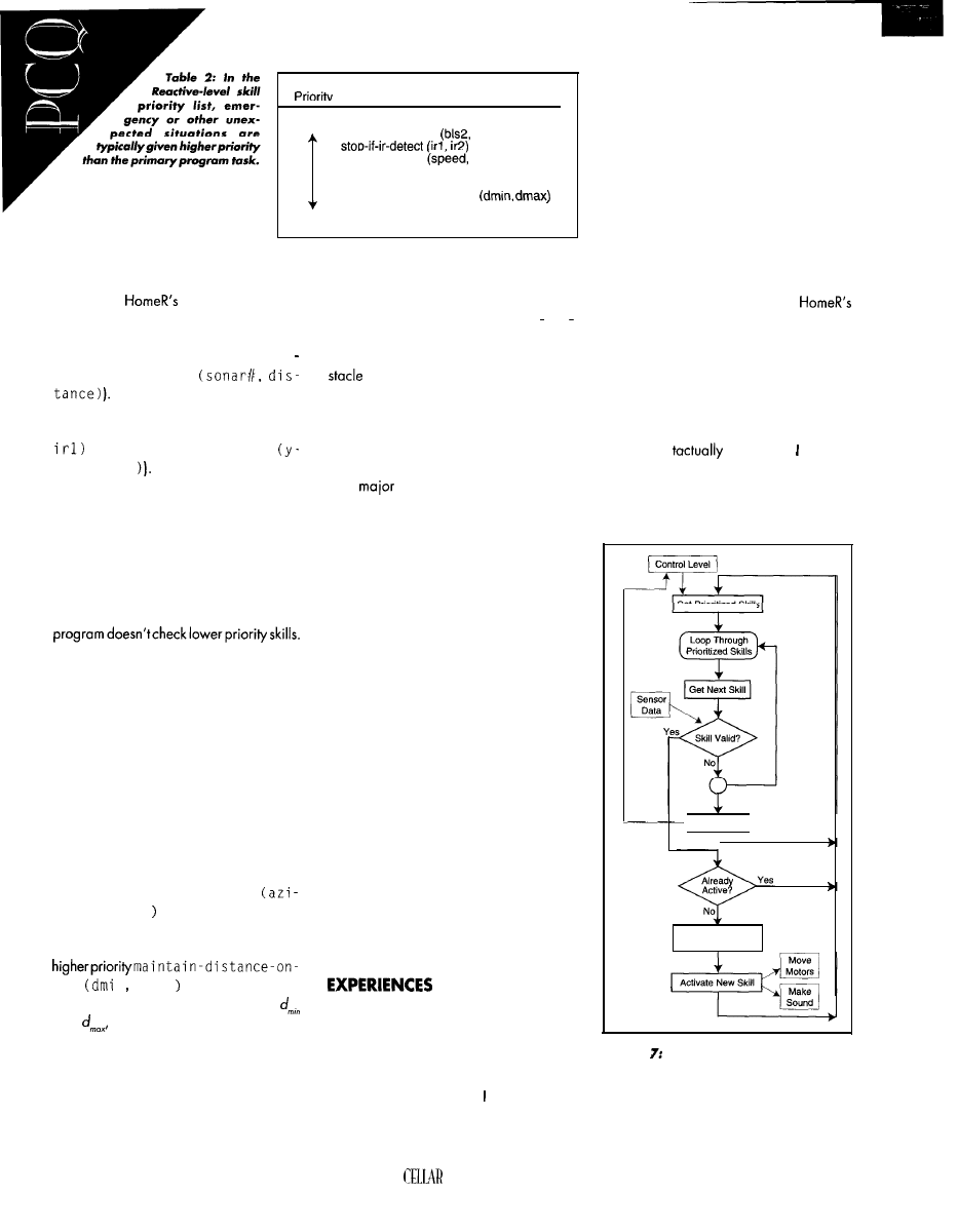
Skill
High
backup-if-bumper-hit (back-dist, bpl, bpr)
stop-if-bumper-hit
brs3)
slow-if-ir-detect
ir3, ir4)
stop-if-high-motor-current (max-current)
stop-if-battery-low (min-charge)
maintain-distance-on-left
sensor data and, if necessary, pro-
duces an action based on the sen-
move-in-direction (azimuth, speed)
Low return-to-control-level
sor data and certain numerical parameter
values. Table 2 offers some examples.
Some of
skills are simple and
absolute(e.g., emergency-stop). More
sophisticated skills involve continuous moni-
toring of sensor data (e.g., ma i n t a i n
c o n s t a n t - d i s t a n c e
Also, the same skill function can
be used with different parameter values
(e.g.,slow-if-ir-detect
( x - s p e e d ,
v s . s l o w - i f - i r - d e t e c t
speed,
i r2
But, unlike the standard Subsumption Ar-
chitecture, behaviors (skills) do not neces-
sarily time out.
Thus, if something activates stop i
f
bumper-hit,
the robot remains stopped
until the bumper is no longer hit (the ob
moves) or the Control level changes
the priority list. This dependency is cru-
cial-the robot cannot usefully operate
using the Reactive level alone.
C O N T I N G E N C I E S
Figure 7 illustrates the Reactive-level
operation. This level always contains a
prioritized
list
of active skills. During execu-
tion, the program sequences through the
prioritized list, and each skill function is
evaluated against sensor inputs.
If a function evaluates as true, that skill
is activated. Once a skill is activated, the
Rather, it returns to the top of the list to
reevaluate higher priority skills.
A
problem for roboticists is bal-
ancing goal achievement against contin-
gency handling. But, it’s surprisingly easy
to get the robot in situations where contin-
Designing robots to operate in the real
world would be much easier if the world
was simple and unchanging. But, the num-
gency handling seems to be its primary
ber of ways things can go wrong exceeds
the normal modes of operation.
purpose.
At first glance, this may resemble Con-
trol-level flow, but there’s an important
difference. When a Control-level action is
activated, the program waits until the ac-
tion completes before going to the next
action. When a Reactive-level skill function
is activated, the program immediately re-
evaluates the prioritized list. Then, if any
higher-priority skill is activated, it overrides
the currently active skill.
Many things conspire to make a robot’s
life difficult. Obstacles move, wheels slip,
sensors break or give false readings, bat-
teries discharge, and doors open and close.
It’s easy for a robot to get “lost” or exhibit
oscillatory behavior.
For example, the program may be ex-
e c u t i n g m o v e - i n - d i r e c t i o n
muth, speed
when the robot gets too
close (i.e., less than distanced,,) to a wall
on the right side. This behavior causes the
1 ef t
n
dmax
to activate instead.
Increasing the number of sensors may
increase the chance of recognizing prob-
lems, but it also ups the probability of a
failed sensor. Also, the more capable the
robot, the more possibilities there are.
Since the same failure in different environ-
ments may require different responses, the
number of potential contingency actions
becomes mind-boggling.
Once the distance is again between
and
move activates. If a specified
bumper is hit, stop-if-bumper-hit
activates and overrides any currently ac-
tive skill. Table 2 simply illustrates the
concept, but a typical list is much longer.
The Reactive-level operation is similar to
Rodney Brooks’ Subsumption Architecture.
The obvious question is: How well does
HomeR work? The answer: By experimen-
tal standards, it works OK. By home-appli-
ance standards, it has a long way to go.
The vacuum and motioncontrol systems
arevirtually problem free. If control HomeR
via the infrared remote, it appears to work
very well.
But, when HomeR runs autonomously, it
stops for no apparent reason, oscillates
between two actions, runs into things its
sensors don’t see, and generally exhibits
unintended behaviors. Despite careful and
conservative electronics design, random
glitches occasionally occur.
The hard reality is that anytime HomeR
runs autonomously, I’m close by with my
finger on the remote Stop button.
F U T U R E D E V E L O P M E N T S
For all practical purposes,
mechanical design is complete. Although
the basic chassis design has evolved con-
siderably, a clean-sheet redesign would
certainly be lighter, simpler, and more
compact.
However, even by the standards of a
simple insect, HomeR is virtually deaf,
blind, and
insensitive. want to
add technologies such as a flux-gate com-
pass and pyroelectric detectors. Another
useful addition would be a sound board to
Get Prioritized Skills
No Valid Skill
I
Deactivate Existing
Active Skill
F i g u r e
T h e R e a c t i v e - l e v e l p r o g r a m
sequences through the prioritized skill list
provided
by the Control level. When a valid
skill is found, it executes until no longer valid
or until a
higher priority skill becomes valid.
if no valid skill can be found, the Control level
is notified to
revise the priority list.
54
CIRCUIT
INK APRIL 1997’
give HomeR more user-friendly human-like
speech.
Software is the
key
enabling technology
in autonomous robotics, yet it is by far the
least mature. Determining the propertypes,
parameters, and sequences of Delibera-
tive-level operations, Control-level actions,
and Reactive-level skills is quite difficult.
Making sense of sometimes contradictory
sensor readings is far from being solved.
From a technical standpoint, a complex
project like HomeR is never completed.
Rapid advances in hardware technology
and constantly evolving software para-
digms seem to make changes obsolete
before they can be fully implemented. Fur-
thermore, autonomous mobile robots are
so new and rare that there are no generally
recognized standards for comparison.
Though haven’tfullyachieved
nal goals, I’ve learned a lot. And with
HomeR (and perhaps its successors), ex-
pect to learn even more.
is an electrical engineer with
over years’ experience in
ogyconsultingandscientificprogramming.
/-/is areas of interest and expertise include
computers, electronics, artificial intelli-
gence, and robotics. You may reach Frank
at
SOURCES
Computers, Inc.
990
Ave.
Sunnyvale, CA 94086
(408) 522-2 100
Fax: (408) 720-l 305
c++
Borland International
100 Borland Way
Valley, CA 95066
(408) 43 l-1 000
digital input board,
analog board
Inc.
125 High St.,
6
Mansfield, MA 02048
261-l 123
Fax: (508)
quadrature optical motor
encoders
Hewlett-Packard
Components Group
370 West Trimble Rd.
San Jose, CA 95 13 1
(408) 435-7400
NMH-05
DC-to-DC converter
International
Power Sources
200 Butterfield
Dr.
Ashland, MA 0172
(508) 88 l-7434
MOS
driver
International Rectifier
233 Kansas St.
El Segundo, CA 90245
(3 10)
1
servo-motor controller board
Mesa Electronics
4175 lakeside D., Ste. 100
Richmond, CA 94086
223-9272
2 2 3 - 9 5 8 5
10)
transducers
Polaroid Corp.
1 19 Windsor St., 2-B
Cambridge, MA 02 139
(6 17)
1
Fax: (6 17) 577-32 13
1101 N. Raddant Rd.
Batavia, 605 10
(708) 406-0900
Fax:
68HC 11,
bus
Processing Innovations Robotics Research
10471 S. Brookhurst St.
Anaheim, CA 92804
(714)
Very Useful
413
414 Moderately Useful
4 Not Useful
DOS IN ROM!
programs
to
in
The
protection
to install half-size
1 4 4 m
$ 1 5 0
5
$ 1 9 5
d i s c o u n t s !
$95 EPROM
PROGRAMMER
Super
Fast
P r o g r a m m i n g
to use
t h a n o t h e r s
Does
M e g ]
Professional, high-performance
:ime multitasking system for DOS
Embedded Systems.
Borland UC++,
UC++, and Borland Pascal.
Libraries: $550 Source Code: add $500
Cross
S stem
for 32-bit Embedded ystems.
Support!
386 and
for
UC++.
UC++.
Libraries:
Source Code: add
2
Professional, high-performance real-
time multitasking system for 32-bit
Embedded Systems.
Supports
Intel 386 and higher.
For Borland UC++,
UC++, and
UC++.
Libraries:
Source Code: add
h
Other Countries:
Hamburg, GERMANY
fax

It’s
Your
BIOS
There’s a problem. You know how to solve it. You
play
God
and make
a great masterpiece. But, incompatibilities between system components and
problem restraints are making your solution formless and void. Fred
ost of you must think that writing for
a top-notch magazine like
a glamor-
ous detail. Well, it is. But sometimes we
authors do have to work. Like today.
The sun is shining, and the oranges on
the backyard tree are ripe. I’m working on
my year-round tan, and it’s just another
sunny day in Circuit Cellar’s Florida Room.
To make things even brighter, a big
overnight package is sitting on the front
porch. Grammar Engine! Smells like a
project to me!
While sipping fresh orange juice,
open the box to see what new concoction
Scott sent. A
Grammar’s ads
always talk about, how pretty this little
marvel is. must admit it’sverycute. It looks
well engineered, too.
Ever turn over a puppy or kitten to “see
what it was”? Well, I turned over my new
to find that it could emulate 2716
(2 KB) through
(5 12 KB) devices.
There are ports for serial or parallel con-
nections to the host PC and pretty
on
the face for Das Blinkinlight types like me.
56
is a take-charge tool. Auxiliary
signals enable it to reset or interrupt the
target and write to its ROM address space.
If your application is bit crazy, you can
even chain multiple
boxes together.
Digging deeper in the treasure chest, I
find a Forth-Systeme ‘386EX development
system complete with the additional serial/
DRAM/LED/breadboard card. Am I awake?
I spent the rest of the day reading and
absorbing user manuals. The Forth-Systeme
documentation is really skimpy-a
mere 0.132”. I figured this little board
would be either real easy or rock-hard to
train. The
user manual stacks in at
0.518”. As tech manuals go, it’s pretty
good reading.
As I studied my new ‘386EX toy, I found
it helpful to have the
Embed-
ded Microprocessor User’s Manual handy
for quick cross reference (another 1.46”).
D A Y
After careful scrutiny of the tiny
Systeme ‘386EX board, I found that, in
addition to the Intel ‘386EX processor, it
contains 256 Kb of zero wait-state SRAM
and reset logic in the form of a Maxim
MAX707.
Address and bus decoding is provided
courtesy of some highly concentrated Lat-
tice
The Forth-Systeme board also
brandishes a high-quality 32-pin socket
designed to saddle up to 5 12 Kb of boot
EPROM or flash.
The ‘386EX
mentioned an optional
flash file. I was excited. I searched for the
doublechecked
the layout diagram, studied the schematic
and the ‘386EX module to the point of
identifying most of the miniature
mount components, but it just wasn’t there.
Having that flash file would have been
great for this application, but there was no
flash silicon or supporting
Lattice part to be found! No flash is a real
downer, but at least I have
power and lots of available RAM.
Before you or I get depressed, realize
that Intel’s ‘386EX platform is designed to
BIOS comes with this package.
Apparently, the Datalight mini-
BIOS is basic but will run almost any
photo You don’t know how I longed for this screen. Note the Remote Disk installation note.
be fully PC compatible. All the fancy soft-
ware development packages we use on the
big guys can be brought to bear on the
development of any Forth-Systeme
even the ones I cook up!
DAY THREE
The hardware seems pretty straightfor-
ward. have the usual complement of
compatible peripherals with the Intel
ROM and RAM address space,
and a couple serial ports.
There’s always a no-count, lazy-butt PC
around to host. And, if the application or
hardware needs to talk to something more
stupid, a dumb terminal is within reach.
Now what? I’ve got this jazzy sports
car, but can’t put gas in it. No BIOS. No
operating system. No code! Arrgghh!
Once again, face the engineer’s di-
lemma-buy it or build it?
DAY FOUR
need a flexible BIOS and OS.
The Forth board lacks a video adapter,
so I need to be able to view stuff over the
serial port. It doesn’t have physical
drive capability, so embed some type of
bootstrap code and OS in ROM, although
it would be great to use “something else’s”
physical drives.
Wish I had some flash, too, but you
can’t have everything. If this application
puts me in the parallel-port mood, I’d better
heat up the soldering iron ‘cause there ain’t
no physical parallel-port interface on the
add-on card either.
With all these “ain’ts,” maybe you think
the Forth board is weak. Not so. The entire
‘386EX part is pinned out to accommodate
any possibility, and all standard ISA-bus
signals are available. Plus, if you get solder
happy, there’s plenty of breadboard area.
At this point, decide to buy. What
software do I have on the shop shelf?
AnnaBlOS looks
good.
The documenta-
tion is friendly and concise. The code
seems very modular with lots of software
switches to pull and tug on.
But, I need a particular debugger as well
as an 80x86 assembler and C compiler just
to get started. I don’t see any options or
examples for redirecting the console I/O.
The next logical step is to check
AnnaBlOS tech support for additional info.
I logged on to their Web page and BBS
and sent up an SOS. Nada. Looks like a
bunch of trial-and-error programming is in
my future.
AnnaBlOS is a good package, but it
seems better suited for the standard fea-
ture-loaded embedded configurations,
which in this case, I
don’t have. I love
to code and debug, but not today.
I need a good OS, too. Lo and behold,
there’s Datalight’s ROM-DOS developer’s
Photo 2: Here’s the business end. It’s where my C application will reside.
I’ve used this soft-
ware before with great suc-
cess. I remember that a
generic PC-compatible configuration. It’s
worth a shot.
It also says that the serial port is sup-
ported as a console. Perfect! I only need an
80x86 assembler and C compiler (Bill’s or
Borland’s), and there’s even an example of
how to do it. Plus, it has a ROM disk
generator. It’s all I need!
DAY FIVE
Up bright and early. Laid in bed all
night, and counted bytes roaming on ad-
dress ranges in the
All standard BIOS code resides in a
memory area that enables the CPU to reset
and hand control to the BIOS routines.
Usually, this 64-Kb area starts at
Datalight’s
occupies the upper
8 Kb of this space. ROM-DOS slides in at
the beginning of the
block.
The whole idea is for the BIOS to turn on
all the ‘386EX goodies and pass control to
a user routine or, in my case, ROM-DOS.
I’m not worried about the application at this
point. I want the
BIOS
to tickle the hard-
ware and take ROM-DOS out on the town.
So, I assemble the
and every-
thing seems OK. Being a
at heart,
I pull up the newly created
code
in a
binary
editor
to
my handiwork.
What’s this “Intel ‘386 Evaluation
Board” stuff in the BIOS banner? I’m not
using that. Uh-oh! Well, what the heck.
I went ahead and built ROM-DOS and
images in hopes that this whole
match would workout. I placed the
images into the
at their specified
addresses and hit the CPU reset button.
Nothing. Nothing on the terminal window.
No banner. April fools!
I’m not shy, so I dial
at Datalight
tech support. Last time we talked, it was a
“pilot error” situation with ROM-DOS. You
know, nut loose behind the keyboard.
Hopefully, the same would be true now.
She confirmed that my code-module
placement was correct and everything
should work. Something just wasn’t click-
ing with the Forth board and the
After some investigation, Jamie informed
me that Datalight’s engineering staff was
currently working on some Forth-Systeme
57
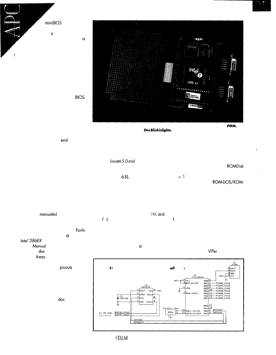
code. Great!
When would it be avail-
able? “In couple weeks.”
It was time for me to do
Bohemian Rhapsody with Freddie
and Queen. If you’re not familiar with
the song, its story line has to do with
murder, lost love, and the fantasy of life. In
the end, nothing in life really matters to
Freddie. (Nothing really matters...hmmm.
Not a bad idea about now.)
DAY SIX
If at first you don’t succeed, read the
manual again. This time, I noticed a
generating company called General Soft-
ware claimed to support my Forth-Systeme
configuration.
After minor phone tag, I found that
General Software’s BIOS is incorporated
into some Forth-Systeme boards-includ-
ing mine! Yahoo!
Problem. I couldn’tgetan
copy. But,
the rep told me he’d E-mail the user manual
and that
the
Grammar
Engine
folks
already
had a workable firmware solution for me.
“Yo, Scott, you got the goods?” Turns
out the General Software rep was right.
DAY SEVEN
The Fed Ex delivery person put a rather
large, heavy package on the porch. Manu-
als! That 0.132” ‘386EX folder just be-
came 3.83” thick-excluding the three
high-quality binders!
But, what’s this? A 32-pin PROM? Can’t
be! I’m about
out by now, so I
take a logical approach to figuring it out as
quickly as possible. I “speed” read.
As it turned out, part of the new
Systeme documentation was reprint of
the
Embedded Microproces-
sor User’s
with the companion
‘386EX folder
in German. April fools!
Naturally,
the first manual I picked
up. You can imagine my panic. At least the
technical descriptions and
were in
English. Does anybody out there know
what an “Entwicklerpaket” is?
Editor’s note: Yes, Fred. It’s a developer’s
package.
Another section contains Datalight’s
ROM-DOS and Card Trick
That leaves
the General Software embedded
BIOS
and DOS sections. So, I’ve eliminated
(through experience) two binders. There’s
still that mystery IC and seven diskettes to
peruse.
photo 3: The
players include the Forth-Systeme Module (shown here) and the
The
expansion board also includes
IT’S ALIVE!
And on the seventh day, he rested.
Whoa! That’s another story.
The diskettes were evaluation copies of
Paradigm
Debug, Datalight
Card Trick and ROM-DOS 6.22, and Gen-
eral Software’s Embedded BIOS 3.0 and
Embedded DOS
Of these, I chose the
DOS/Card Trick suite and General
Software’s BIOS.
There are over 170 configuration op-
tions that cover a wide variety of system
BIOS designs. I could write a couple ar-
ticles just on building up BIOS for this
project.
To generate a working BIOS, simply
read the excellent General Software docu-
mentation and configure two header files.
The BIOS programmer can concentrate on
twoconfigurationfiles,OPTIONS.
CON I
.
I NC, instead of changing parms
in over 50 BIOS source files.
For now, in addition to the normal BIOS
stuff, the serial console redirection and
remote disk-access features make the Gen-
eral Software and Datalight product suite
the ticket for my application.
Generating ROM-DOS and
is an automated process. Datalight includes
a B i d program that walks you through
assembling a working
Disk image. No worries here.
What’s left? There’s a single sheet of
what seem to be instructions with that
mystery IC. Hey, I’ve learned. When in
doubt, read.
Connect a dumb terminal to serial port
Instead, I used a Windows 95 DOS
window running the COMM program that
comes with Datalight’s Developer Kit. This
way, I can show you what happens. Done.
Connect COM2 on the ‘386EX board
to a serial port on the host PC. Instead of a
desktop PC, Teknor’s
embedded PC
Figure Simple, yet effective. You can
hang sorts
of things off a PIC.
58
CIRCUIT
INK APRIL 1991
Remember, there’s
no physical parallel port
on
board. And, I’m
not going to add complexity and
parts when can accomplish the task
with resident hardware and software.
With a working DOS, can write a
driver in C or any other high-level language
to interface with the
controller. This
controller
standard micro programmed
to interface eight
to the second
‘386EX serial port.
Here’s how it fits together. The C pro-
gram monitors the
controller via the
with a full complement of disk peripherals
is the host. After all, I’m writing for the
section. Done.
Run the REMSERV program included on
the binary image diskette. Of course, be-
fore you do all this, install the included
PROM in the EPROM socket on the
Systeme module. (You know, this process
brings another song to mind, “Won’t get
fooled again” by The WHO.)
In goes the EPROM. On goes power. A
General Software BIOS banner and
DOS is initializing. Photo 1 appears. If Scott
were here, I’d kiss him. Well, maybe not.
Notice the
A
prompt. This is the
image. Photo 2 is a directory
listing of the Flash-Disk designated as drive
B. Yea, flash at last! Also, there’s a drive C
that equates to the
physical hard
drive.
REMSERV provides a way to redirect
disk-access requests through the
and
Forth-Systeme serial ports. use the
C drive to load the Flash-Disk B drive with
my application.
Thanks to
Trick, I can emulate that flash I was yearn-
ing for with some of the
Finally, I’m where I want to be. A
working General Software BIOS was gen-
erated for the ‘386EX module. A Datalight
em bedded DOS was generated and placed
in ROM address space. And, some tricky
Datalight disk-access code made it all use-
ful.
Just for grins, I copied the PROM con-
tents into a binary image and looked at the
whole landscape using
Beautiful.
PUT IT TO WORK
Yeah, yeah. The future’s so bright, I
gotta wear shades. Let’s get on with it.
Some time ago, I bought some modules
that replace standard AC wall switches
with an automatic proximity switch and
timer. When motion is detected, the light
associated with that wall switch activates
and automatically turns off after a certain
time period. Well, I found some of those
sensors in their raw form, and I’m gonna
put them to work.
The sensor is an AMP
(Passive
Infrared Module) that comes as a complete
package including detector, Fresnel lens,
and electronics. The detector and lens
provide a field of 34 horizontal and 30
beams. Output is an active-high
digital signal activated when motion is
detected within 20’.
For you analog heads, there’s also an
analog output offset at 2.5 V. The
uses a standard +5-V
supply drawing
2
max, so a battery supply can be used
if your application requires it. Photo 3
shows the Forth-Systeme modules.
Lots of applications come to mind. Is
someone in a secure area of an office or
lab? Are they playing in the highdollar
parts bin? Is light necessary in this room if
it’s empty? Do I want my coffee pot to turn
on when I enter the kitchen?
The list is endless, so apply the
technology, and you provide the reason.
your source for the most
powered, comprehensive set of
software and hardware development tools for
embedded
development.
1:
Paradigm LOCATE the most popular tool for
embedded C/C++
with
Borland and
compilers; 2: Paradigm
DEBUG the only x86 debugger
RTOS,
language, and full
emulator
support; 3: Paradigm SUPPORT the best technical
s u p p o r t the
to our
customers free
Developing real-time embedded applications doesn’t have to be
time consuming or difficult-you just need to have the right tools.
Paradigm alone has the high performance development
you
need to streamline the embedded system software development
process so your Intel and AMD x86 applications are ready in record
time. Paradigm’s complete suite of tools work with industry standard
C/C++ compilers from Borland and Microsoft, as well as hardware
development tools from Applied Microsystems, Beacon Development
Tools and other popular in-circuit emulator vendors.
Call us at 800-537-5043 today and Let take care of all your
development tool needs, so you can keep your focus where
you need it-on your application.
l-800-537-504
Rx
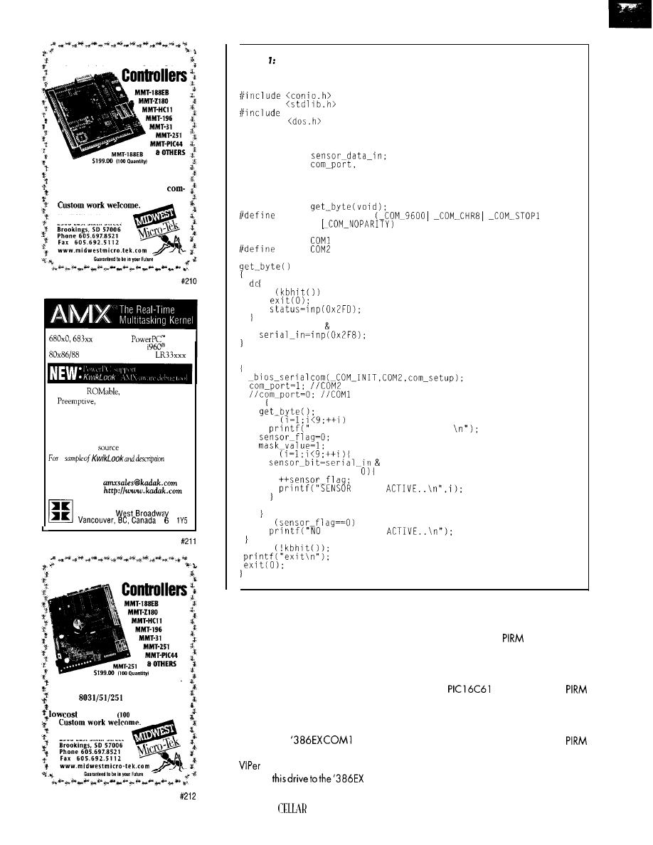
low Cost Embedded
Listing As you see, C is effective in an embedded environment.
If you’re interested in getting the
most out of your project, put the
most into it. Call or Fax us for
plete data sheets and CPU options.
MIDWEST MICRO-TEK
2308 East Sixth Street
80386 protected mode
family
real mode
family
R3000,
80251 Embedded
Midwest Micro-Tek is proud to offer
its newest line of controllers based
on the
architecture.
The 8031 comes in at a surprisingly
of $89.00
quantity).
MIDWEST MICRO-TEK
2308 East Sixth Street
60
l
Compact,
fast interrupt response
l
priority based task scheduler
l
Mailbox, semaphore, resource, event, list,
buffer and memory managers
l
Configuration Builder utility
l
Comprehensive documentation
l
No royalties,
code included
a
of
AMX,
Phone: (604) 734-2796
F a x : ( 6 0 4 ) 7 3 4 . 8 1 1 4
E-mail:
W e b :
KADAK Products Ltd.
2 0 6 - 1 8 4 7
V J
i/include <stdio.h>
#include
<bios.h>
l/include
unsigned char serial-in,
mask-value,
sensor-bit,
unsigned int
sensor-flag,
status,
i;
void
corn-setup
#define
if
while ((status data-ready) != 0x01);
void main0
do
for
for
mask-value;
if (sensor-bit !=
%d IS
mask_value=mask_value << 1;
if
SENSORS ARE
while
‘386EX COM2
serial port. The serial data
received by the program is an eight-bit
word with each bit corresponding to a
sensor. If the bit is 1, the sensor is on.
This program can be embellished to
include things like room numbers or bin
locations per sensor. My program simply
tells the user which sensors are active.
Since the video is routed to a serial port,
these messages appear on the terminal
attached to the
serial port.
The compiled C program is placed on
the
C drive. Just make a DOS copy of
thefilefrom
Bdrive.
CIRCUIT
INK APRIL 1997
From there, kick off the C program as you
would on a desktop PC. Listing 1 tells all.
To most of us, the
controller is an
old friend-a PIC. The type doesn’t really
matter as long as there are enough I/O
pins to accommodate your sensors.
The
I chose for my
controller constantly polls the I/O port
attached to the sensor array.
When a sensor detects motion, that
particular I/O pin goes high and the
controller sends an eight-bit data packet to
the C program. It decodes the bit pattern
and displays a user-defined message.
The data packet is an image of the I/O
port pins. Need more sensors? Add PIC I/O
ports and send more data packets. Figure
1 shows the
schematic.
PAY DIRT
By using some really sweet DOS and
BIOS code modules from General Software
and Datalight, along with the Forth-Systeme
module and one smart Microchip
IC, I’ve transformed my little
evalu-
ation kit into a useful device.
I could have written some
patible C code and embedded it or done it
without any BIOS code. But why?
The headache of embedding applica-
tions is erased by standard
ible tools and code. The Grammar Engine
let me load and test different DOS
and BIOS images with minimal effort. Be-
cause the Datalight and General Software
modules composing the final images are
pretested to a point, I didn’t need to debug.
This application is just a beginning. The
outboard
controller could just as eas-
ily be an array of serially interfaced
or another ‘386EX module running a slave
application. using DOS-compatible hard-
ware and embedding DOS-compatible firm-
ware, I’ve again proven it doesn’t have to
be
to be embedded.
My thanks to Scott
at Grammar
Engine for servicing my spurious interrupts
during production of this article. Also,
thanks again to Jamie
at Datalight
for her sympathetic ears.
Fred Eady has over years‘ experience
as a systems engineer. He has worked with
computers and communication systems
large and small, simple and complex. His
forte is embedded-systems design and com-
munications. Fred may be reached at
SOURCES
1 1838
Plaza Ct.
San Diego, CA 92 128-2414
(6 19) 673-0870
Fax: (619) 673-l 432
Module
B.G.
Micro, Inc.
P.O. Box 280298
Dallas, TX 75228
(972) 2715546
Fax: (972) 271.2462
ROM-DOS V.6.22,
Disk
Datalight
.
188 10 59th Ave. NE
Arlington, WA 98223
(360) 435.8086
.
Fax: (360) 435.0253
.
Embedded BIOS adaptation
.
General Software
320-l 08th Ave. NE, Ste. 400
.
WA 98004
(206) 4545755
Fax: (206) 4545744
Forth-Systeme
Grammar Engine, Inc.
92 1
Dr., Ste. 122
OH 4308 1
(614) 899.7878
Fax: (614) 899.7888
VIPerB06
Microsystems, Inc.
7900 Glades Rd.
FL 33434
(561) 883.6191
Fox: (561) 883-669
4
16 Very Useful
4 17 Moderately Useful
418 Not Useful
O E S Y O U R
B
I G
- C
O M P A N Y
MARKETING DEPARTMENT COME
WITH MORE IDEAS THAN THE
ENGINEERING DEPARTMENT CAN
C O P E
A
R E Y O
U
A S M A
L L
COMPANY THAT CAN’T AFFORD A
FULL-TIME ENGINEERING STAFF
ONCE-IN-A-WHILE DESIGNS?
S
T E V E
C
I A R C I A A N D T H E
D
E S I G N
W
O R K S S T A F F M A Y
SOLUTION. WE HAVE A TEAM OF
ACCOMPLISHED PROGRAMMERS
AND ENGINEERS READY TO
PRODUCTS OR SOLVE TRICKY
ENGINEERING PROBLEMS.
HETHER YOU NEED AN
ON-LINE SOLUTION FOR A
PROBLEM, A PRODUCT FOR A
STARTUP VENTURE, OR JUST
EXPERIENCED CONSULTING,
D
E S I G N
W
O R K S I S
WORK WITH YOU.
UST FAX ME YOUR PROBLEM
AND WE’LL BE IN TOUCH.
connect a keyboard,
monitor/LCD, a disk drive
and your ready to run. Or
forget the drive and boot
directly from a Flash disk.
Add PC/ 104 Modules for
Fax/Modem, SCSI, Ethernet,
and PCMCIA.
Great for Point Of Sale and Wed
Browsers/Servers. Prices start at $200.00 Qty. 1
CPU Selection: 386SX. 486DX. DX2, DX4, 586,
Pentium.
All
have Real Time Clock, Serial. Parallel, IDE, and Floppy.
On Board Watchdog Timer.
BIOS with Power Saving Green Mode.
Wide Bus Selection: PC/ 104. ISA, PCI.
10.4”
super bright LCD Panel Kits.
Hardware and Cable kits included for most boards.
618-529-4525 Fax 457-0110
529-5708
11 EMAC WAY, CARBONDALE, IL 62901
WORLD WIDE WEB:
61
DEPARTMENTS
From the Bench
Joe
Standards for Electromagnetic
Compliance Testing
Immunity and Susceptibility
cussed the
sions tests mandated for
electronic equipment by the FCC and
the European Community (EC). By
limiting the levels of radiated and con-
ducted emissions, these tests set up an
electromagnetic environment for the
coexistence of electronic equipment.
It implies electronic equipment must
be able to withstand a certain amount
of
caused by other electronic
equipment and natural phenomena.
This ability is referred to as immunity
or susceptibility.
In this issue, I look at immunity
standards. Unlike radiated and con-
ducted emissions where the FCC and
the EC are in agreement, there’s no
similarity at all when it comes to im-
munity tests.
The FCC requires no immunity
testing, while the EC requires it exten-
sively. Since the FCC does not mandate
immunity testing for class B digital
devices, it’s up to the manufacturers,
when shipping within or into the U.S.,
to ensure their products can operate
properly in their intended electromag-
netic environment.
This approach has been fairly suc-
cessful with very little government red
tape. Most manufacturers design their
products to meet, and in many cases
62
Issue
April 1997
Circuit Cellar INK@
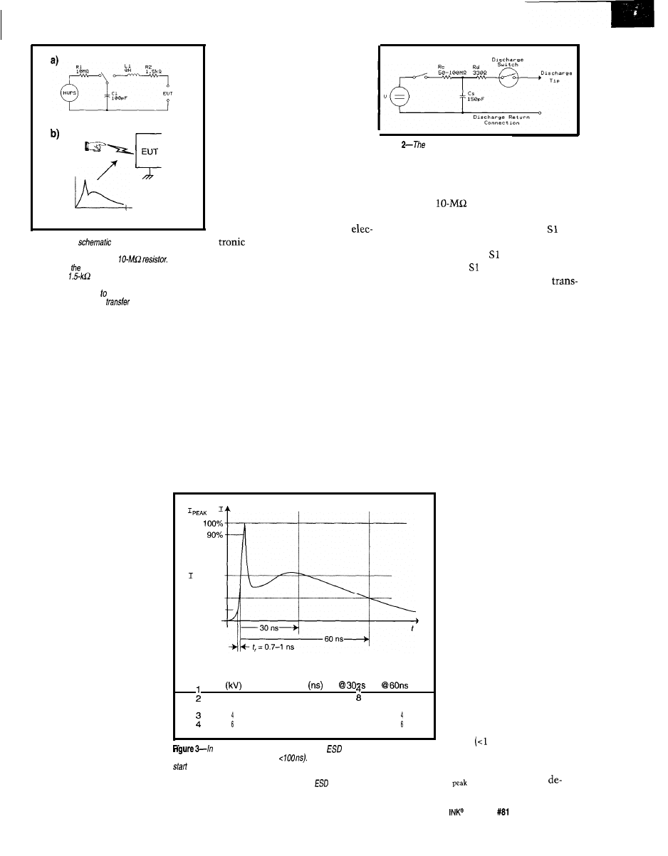
E U T
Time
100 ns
Figure l--This
represents the human body
for ESD events. The charge on the human body is
severity levels along with several
performance criteria. It’s up to
the calling standard to specify
which level of testing is applied.
This allows the IEC series to be
called by a wide range of immu-
nity standards.
ELECTROSTATIC DISCHARGE
Electrostatic discharge (ESD)
Figure
ESD gun used for testing simulates the charge
transfer that occurs between a human and a conducting object.
is
by far the most common transient
by the high-voltage power supply
event that electronic equipment is
(HVPS).
subjected to.
The
resistor charges the
When a person carrying a static
capacitor C 1, which represents the
charge comes in contact with
capacitance of the human body;
equipment, the charge transfer
initiates the charge transfer. In the
To better understand, test, and de-
sign for ESD, the Human Body Model
and potential equalization can cause
(HBM) was developed. The HBM simu-
lates the discharge event that occurs
when a person charged with positive or
negative potential comes in contact
currents in the tens of amperes. These
with electronic equipment. Regulators
use the HBM to determine ESD test
procedures.
currents and their thermal effects
cause traces and components in the
electronic equipment to fail.
Figure
la
shows the equivalent
schematic of the human body for ESD
purposes. The model shows that a large
static potential is built up, represented
is not transferred when the person
physically contacts the electronic
left-hand position, represent a static
equipment. The charge arcs from the
person to the equipment in that very
short time period when the person is
close enough to, but not actually touch-
charge. When is switched to the
ing the equipment.
We’ve all walked across carpet and
touched a metal door knob. Just prior
right-hand position, the charge is
to making physical contact, we get the
familiar shock. But, after we make
physical contact, we feel nothing. Keep
ferred to the EUT.
this in mind since it has bearing on the
ESD test procedures.
As you see in Figure lb, the charge
exceed, the immunity requirements
acquired slow/y through the
However,
set up by the FCC emissions stan-
dards.
charge from human body is released quickly
through the
resistor (a). The charge transfer
between a person and electronic equipment fakes p/ace
in that short time prior physical contact. The current
waveform of the charge
is shown here (b).
Competitive pressures ensure that
most manufacturers do not cut corners
on immunity. However, there are
always some manufacturers that cut
corners to reduce costs or, more com-
monly, do inadequate testing.
As the electromagnetic spectrum
becomes more crowded, the immunity
issue will be much more important.
If products had a higher level of
immunity to radiated and
conducted emissions, many
EM1 problems could be
avoided. This is one of EC’s
main arguments for immu-
nity testing.
For a product to be sold
into the EC, it must meet
both an emissions and an
immunity standard. Each
immunity standard calls
other technical standards to
outline the actual tests.
at 30 ns
I
at 60 ns
10%
The technical standards,
the IEC 1000-4 series of tests,
are quite extensive. 1’11 dis-
cuss the three most com-
mon-electrostatic discharge,
electrical fast transients/
bursts, and radiated electro-
magnetic fields.
Severity Voltage First Peak Rise Time Current
Current
Level
(A)
(A)
(A)
2
2
8
7.5 15
0.7-l 0.7-l
22.5 30
0.7-l 0.7-l
12 16
8
Each IEC 1000-4 series
standard specifies the test
method and gives several
a current waveform produced by an
gun, the charge is transferred
in a very short period of time (i.e.,
The large, extreme/y fast spike at the
of the waveform simulates the initial charge transfer or spark that occurs when a
charged human body comes in contact with a conducting object. The ESD-gun
waveform parameters are established by the
test standard IEC 1000-4-Z.
ESD GUN
An ESD gun tests equip-
ment for ESD and must be
capable of reproducing the
waveform in Figure lb. Fig-
ure 2 shows a simplified
schematic of an ESD gun.
The ESD gun is quite
simple. The storage capaci-
tor Cs is charged through
resistor Rc and discharged to
the EUT via Rd. The switch
is usually a vacuum relay
and is manually operated.
Figure 3 is a detailed
drawing of the ESD current
waveform. Note that the
initial pulse is extremely
short
ns), and the total
waveform time is in the
order of 100 ns. The current
I
in Figure 3 varies
Circuit Cellar
Issue
April 1997
63
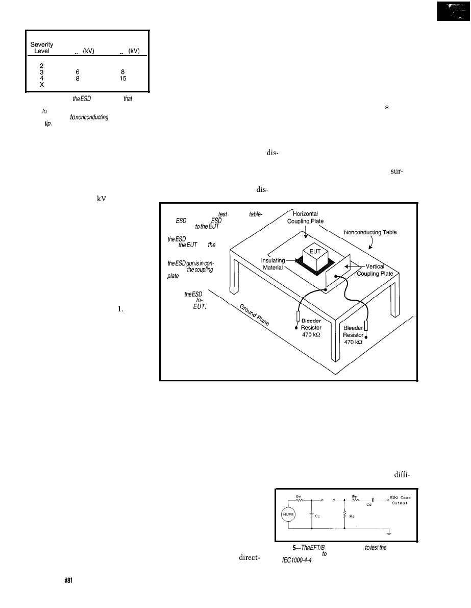
Contact
Air
Discharge Test Discharge Test
Voltaae
Voltaae
1
2
2
4
4
Special
Special
Table l--These are
severity levels
a
calling standard can dictate. Contact discharge is
applied conducting surfaces with a sharp fip, while air
discharge is applied
surfaces with a
rounded
pending on the severity level. These
waveform parameters are given in the
table in that figure.
The ESD gun has two tips-a sharp
tip for contact discharge and a round
one for air discharge. The gun must
provide the waveform in Figure 3 at
voltage levels up to 15
in both posi-
tive and negative polarity. The ESD gun
has a ground strap that’s connected to
the ground plane to provide a return.
ESD TESTS
The standard for ESD testing and
measurement techniques is IEC 1000-4-
2. The ESD test is fairly simple. It con-
sists of applying an ESD to all points on
the EUT that are accessible to an op-
erator during normal operation. The
test levels are given in Table
Contact or direct discharge is the
preferred method of testing. Even
through air, discharge is more represen-
tative of the actual ESD event. Air
discharge is used where direct discharge
cannot be applied (e.g., to nonconduct-
ing surfaces). To simulate an ESD event
close but not on electronic equipment,
indirect discharge is applied.
Figure 4 shows the test setup. The
EUT is placed on a nonconducting
table 80 cm above a ground plane. A
horizontal coupling plane is put on the
table but insulated from the EUT.
A vertical coupling plane is also
used, but it must be movable. The
ground plane on the floor is connected
to the mains ground, and the coupling
planes are connected to the ground
plane via bleeder resistors.
INDIRECT DISCHARGE
When an ESD occurs in close prox-
imity to electronic equipment, the
radiated and conducted emissions
produced can affect the EUT. To simu-
late this, the ESD gun is placed in
contact with the coupling planes and
then discharged.
A minimum of four contact points
for both the vertical and horizontal
coupling planes ensures that full cover-
age can be effected. In the case of the
horizontal coupling plane, it’s a matter
of choosing four points-one on each
of the four sides of the EUT, but no
further than 0.1 m from the EUT.
For the vertical coupling plane, the
contact test is preferred since its re-
sults are repeatable. All conducting
and operating parts of the EUT that a
user can contact under normal condi-
tions must be tested.
The ESD gun is brought into contact
with the EUT, and then the ESD gun is
triggered. Normally 10 discharges are
applied with a minimum of
1
between
ESD triggering. Again, the levels start
out low and work their way up, testing
both polarities.
AIR DISCHARGE
Where direct discharge cannot be
used (i.e., with nonconducting
faces), air discharge is used. The ESD
gun is fitted with the rounded tip.
discharge point is the center of the
plane. This plane is placed no further
than 0.1 m from the EUT and the
charge is applied. All four sides must
be illuminated.
Normally 10 discharges per point
with a l-s minimum between
Figure 4-/n
a typical
setup for
fop
testing, an
gun charge is
transferred
by one of
three ways. Transfer is direct if
gun is in contact
with
and
gun is discharged.
Transfer is indirect if
fact with
and then dis-
charged. Air dis-
charge involves
moving
gun quickly
ward the
simulating normal hu-
man contact.
charges is applied. Test levels start at
the lowest
voltage
level and work up,
testing both polarities.
The indirect-discharge test is almost
always performed first, since it is the
least severe. Failures are normally non-
fatal, consisting mostly of the equip-
ment hanging or resetting.
moved towards the EUT as quickly as
With the trigger closed, the ESD gun is
possible and contact is made with the
EUT.
Such failures contrast with the di-
rect- and air-discharge portions of the
ESD test, where permanent dam-
age can occur. Therefore, until
the equipment passes the indirect
discharge test, it’s unwise to try
the other two parts of the test.
This technique closely simulates
what happens when a person comes in
contact with electronic equipment.
Unfortunately, with this test, it is
difficult to get repeatable results. The
speed and angle of approach are
DIRECT DISCHARGE
Although less representative of
an actual ESD event, the
Figure
generator is used
immunity of
electronic equipment switching-type transients as mandated
by
66
Issue
April 1997
Circuit Cellar INK@
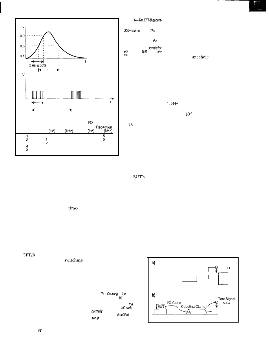
50 ns 30%
15ms
300 ms
Power Supply Ports
Ports
Severity
Voltage Repetition
V o l t a g e
Level
Peak
Rate
Peak
Rate
0.5
3
5 5
0.25 0.5
5
1
5
4
2.5
2
5
Special
Special
cult to reproduce, not to mention the
fact that the equipment tends to get
damaged.
As with the direct and indirect
tests, normally 10 discharges per point
are made. They start with the lowest
voltage level and work up, testing both
polarities.
The ESD test can be quite
consuming. And, since test labs charge
by the hour, this is one test you do not
want to repeat.
FAST TRANSIENT/BURST
The standard for electrical fast tran-
sient/burst (EFT/B) testing and mea-
surement techniques is IEC 1000-4-4.
The
test checks the immunity
of electronic equipment to
transient-type interference. Common
sources are the switching of inductive
loads and relay bounce. The test is
applied to the EUT power and I/O
[data, control, and signal) ports.
A simplified circuit diagram of the
test generator is shown in Figure 5.
The test signal consists of a series of
individual pulses applied in bursts.
Figure 6 shows the waveform of the
individual pulse and the complete test
Figure
for
produces a train of pulses
which last 15 ms during a
frame.
indi-
vidual pulses are we//-defined.
The voltage /eve/ of the applied
voltage V depends on se-
verity/eve/ applied. The calling
standardspecifies
for various voltage
and repetition
rates.
signal. Individual
pulses are quite
short (i.e., -50 ns)
with burst durations
of ms and burst
periods of 300 ms.
Individual pulses
have several repeti-
tion rates depending
on the test level.
The table in Figure 6
gives these as well
as the voltage peaks.
The test signal is directly or indi-
rectly coupled into the
lines.
Normally, for power ports, the signal
is coupled in via a coupling network,
and for I/O lines, a coupling clamp is
used. Figure 7 shows simplified ver-
sions of both coupling techniques.
For a given piece of test equipment,
there could be several different test
setups, so it’s not possible to show a
typical setup. Once a test setup is
established, the application of the test
is quite simple. Each power and I/O
port is subjected to the test signal of
Figure 6.
RADIATED EM FIELDS
The standard for EUT
immunity to radiated elec-
tromagnetic fields (REF)
Figure
of
fast
transient
burst signal either AC or DC
power pork is normal/y done via a
coupling network. Coupling of fasf
transient burst signal to
is
done via a coupling c/amp.
b--Here, you see a
test
testing and measurement techniques is
IEC 1000-4-3. The REF was designed to
test the EUT immunity to radiated
electromagnetic fields.
The test is quite simple. The EUT
is placed on a nonconducting table in a
controlled electromagnetic environ-
ment (e.g., an
chamber). A
transmitting antenna is placed at a
distance from the EUT. The antenna
radiates a field such that at the EUT a
known field strength exists.
Figure 8 shows the test setup. The
antenna is driven by a sine wave in the
frequency range of 80-1000 MHz,
which is amplitude modulated by a
sine wave to an 80% level. The
frequency is swept at a rate no faster
than 1.5 x
decades per second or
stepped at intervals of 1.01 times the
previous step.
EVALUATING TEST RESULTS
Due to the wide variety of electronic
equipment subjected to immunity
testing, result evaluation is done on an
individual basis by comparing test
results to normal operating conditions.
Normal conditions are usually estab-
lished by the manufacturer prior to
testing. They must reflect the normal
operating conditions implied in the
manufacturer’s equipment literature.
The IEC 1000-4 series classifies the
test results as:
l
normal performance within specified
limits
l
temporary degradation or loss of
function or performance which is
self-recoverable
l
temporary degradation or loss of
function or performance which
needs operator intervention or sys-
tem reset
Decoupling Filter _
Test Signal
50
Power Line
Power
EUT
Port
Ground Plane
68
Issue
April 1997
Circuit Cellar INK@
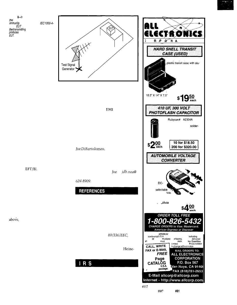
Figure
a simplified test setup
for
radiated-electromagnetic field
test mandated by
3, the
is p/aced at distance
d
from
antenna, which
a known
field strength at fhe
l
degradation or loss of func-
tion which is not recov-
erable due to damage of
equipment or software or
loss of data
A calling standard can use these classi-
fications to evaluate test results or
specify its’own.
The generic standards use perfor-
mance criteria to evaluate test results:
l
A-the equipment continues to oper-
ate as intended. No degradation of
performance or loss of functionality
is allowed during the tests. Criterion
is applied to phenomena that are
continuously present (e.g., REF).
l
B-after the test, the equipment
continues to operate as intended.
During the test, performance degra-
dation is allowed. Criterion is nor-
mally applied to transient tests (e.g.,
ESD or
l
C--during the test, functionality may
be lost. After the test, the equipment
must recover on its own or via the
operator. Criterion is normally
applied to tests that cause interrup-
tions beyond the control of the EUT
(e.g., power-line interruptions).
Prior to starting the test, an evalua-
tion criterion, normally one of the
is selected. The test result is
positive (i.e., pass) if the EUT operates
as intended with respect to the evalua-
tion criteria.
There is some flexibility in evaluat-
ing immunity test results, so to save
time and, of course, money, carefully
select normal operation and evaluation
criteria.
HEADING TO THE LAB
The combination of last month’s
article on radiated and conducted emis-
sions tests and this article on immu-
nity tests gives the minimum test set
that most unintentional radiators are
subjected to.
If you know what to expect, you
can modify designs to increase the
chances of passing
testing on the
first attempt.
Next month, I’ll look at test labs,
how to select a test lab, and what to do
prior to, during, and after the trip to
the lab. Remember that the test labs
normally charge by the hour, so it’s
important to be prepared.
q
l? Eng., has over 15
years’ engineering experience. He
currently works
for
Sensors and Soft-
ware and also runs his own consulting
company, Northern Engineering Asso-
ciates. You may reach
at
sympatico.ca or by telephone at (905)
FCC, Code of Federal Regulations,
Title 47, Parts 15 and 18, 1995.
IEC Standard 1000-4-1, Electromag-
netic Compatibility, Testing and
Measurement Techniques, Over-
view of Immunity Tests, Basic
EMC Publication, 1992.
C. Marshman, The Guide to the
EMC Directive
EPA
Press, Ambo, UK, 1992.
T. Williams, EMC for Product De-
signers, Butterworth and
mann, Oxford, UK, 1996.
419
Very Useful
420 Moderately Useful
421 Not Useful
0
T
I 0 N
Heavy-duty, impact resistant
minum hinges and trim and
metal clasps. Black crinkle
exterior and black carrying
handle. These cases
were used slightly
for moving medical
equipment. They
are in excellent condition.
Exterior dimensions:
CAT # CSE-9
1
0.7” diameter X 1.7” long.
Right angle PC or
leads on 0.25” centers.
CAT# PPC-410
Run audio, communications
and other battery
operated devices
from your car
cigarette lighter.
Regulated
DC converter
supplies
voltages from 1.5
to 12 Vdc at up to 800
milliamps. Adjustable polarity. Includes six dif-
ferent adapter
that fit most eauioment.
CAT # APC-800
TERMS NO
ORDER. Shipping and handling for the
48
$5 00 per order. All others
AK.
HI. PR
Canada
full
All orders
CALIFORNIA
Include local
sales
NO COD
for our
96
Outside the
send $2.00
t
Circuit Cellar
Issue
April 1997
69

Jeff Bachiochi
You Can Take
Finding Your Way,
It With You
Electronically
can’t believe how
wrist radio has
certainly entered the realm of reality
(though it’ll still be a while before we
get teleconferencing on our wrist).
You have to wonder where it will
end up or what will happen to stop it.
For now, I guess we can just ooh and
ahh at new developments.
As a continuation of last month’s
investigation into Precision Naviga-
tion’s Vector 2x compass, I want to
show you how I interfaced this module
to a microprocessor combined with an
LCD and regulated power supply.
I created a portable electronic compass
like the one in Photo 1.
Let’s start with a little background
on how the 2x module creates a bearing
output from the earth’s magnetic field.
RIDING MAGNETIC LINES
Since the earth’s magnetic lines of
force affect a coil like any other mag-
netic field, coils can be used to mea-
sure the force of the earth’s field.
PNI uses the coil as part of an oscil-
lator in their Vector 2x compass mod-
ule. The oscillator’s frequency changes
with the strength of the magnetic field.
The frequency deviation is at its
maximum when the coil aligns parallel
to the earth’s magnetic field and at its
minimum when the coil is at right
angles to the field. North and south
can be easily determined, but east and
west are still a bit nebulous.
Now, duplicate the same circuit,
placing coils at right angles to one
another-one at maximum deviation
and the other at minimum. The out-
puts then vary like the sine and cosine
of a particular angle.
With magnetic compasses, you must
watch your surroundings. Close prox-
imity to metal objects draws the earth’s
lines of force from their natural paths.
Mechanical compasses cannot compen-
sate and are drawn toward the-object.
Although the Vector 2x module
compensates for static magnetic fields
created by hard-iron distortions (e.g.,
the metal frame of your automobile), it
doesn’t have nonvolatile memory to
store this calibration setting. Calibra-
tion is lost along with power.
If you use the module in a situation
where calibration is necessary and don’t
want to manually calibrate it each time
you power up, you must use it in the
Raw mode. The Raw mode calculates
and stores the calibration externally.
One calibration constant is needed
for each axis (x and y). In Raw mode,
the module outputs a 16-bit signed
number for the x-axis followed by a
signed number for the y-axis.
The signed numbers reflect the
relative field strength picked up by
each of the coils. The coils’ output
should be equal but opposite when the
module is rotated 180”.
Under perfect conditions, the lines
of force move in a straight path. But,
when a distortion is present, these
lines move toward the source of the
distortion as shown in Figure This
curve translates into a difference in
measurements between two readings
Compass
Compass Affected
NOT Affected
by Metal Pole
Earth’s Magnetic
Lines of Force
Figure
metal
object can indeed affect earth’s
magnetic lines of force just like
is drawn toward a
black hole.
of the same coil
(180”
from
one another).
To calculate the offset
constant for each axis, use
the formula:
2
where is the offset con-
stant for the x-axis, and
and are the first two 16-bit
signed numbers from each of
the two Raw mode readings
taken
apart.
Similarly, is the offset
constant for the y-axis, and
and are the second two
D3
D O
Function Set
0 0 1 DL high nibble
N F X X
low nibble
where DL: l&-bit mode,,
mode
N:
lines,
F:
x 11 dots/char,
x 7 dots/char
X: don’t care
D i s p l a y O n / O f f
0 0 0 0
high nibble
1
D C B
low nibble
where D: 1
On,
Off
C:
On, O=cursor Off
B:
blink, O=cursor steady
Shift Set
0 0 0 1
high nibble
S I C
X
low nibble
where S/C:
shift, O=cursor shift
R/L:
right, O=shift left
X: don’t care
Entry Mode
0 0 0 0
high nibble
0 1
low nibble
where
, O=decrement
S: 1
shift,
shift
16-bit signed numbers from
each of the two Raw mode readings
taken 180” apart.
These two correction constants can
be stored locally and used to adjust all
future Raw data received while the
module remains at its present location
with respect to the distortion. Each
offset constant must be subtracted from
the Raw data before a bearing can be
calculated using the formulas:
= x
=
where c is the compensated value for
the axis, is the axis raw value, and o
is the axis offset constant.
nibble commands initialize 2 x 8 LCD.
easy access to the battery
without removing screws.
used a simple interface.
Only two control lines are
needed to permanently en-
able the LCD’s enable line.
The
data mode requires
two writes for each charac-
ter, but it’s a good tradeoff
over the
bus width.
Initializing the LCD is a
bit tricky for the 4-bit mode
since the first write is always
in
mode. The
bus
uses bits 4-7 on the LCD.
The first write to the control
register (RS=O) assumes the
interface is 8 bits wide. If the
value 2 (0010) is written on
the nibble bus, it’s read as an
word
(the lower bits are
To calculate the bearing from
don’t care).
use:
This command places the LCD’s
B = tan’
processor into 4-bit mode for the rest
of the command transfers. From now
where the bearing is equal to the
tangent of the compensated x-axis
on, all values must be passed in
or low-nibble format.
value divided by the compensated
Only a few registers need
ing before the LCD can be used. Since
axis value.
most
use the same processor
CHARACTER-CLASS
regardless of their size, the same proce-
Small dot-matrix
usually
dures are appropriate for any of them.
In addition to the control commands
come with a built-in processor for
shown in Table 1, there are also
trolling the dots (segments) and
mands to home the display and cursor
ing control of a
character set.
to location
and to
This eliminates the overhead necessary
for enabling individual
clear the display. Addressable DD (data
display] and CG [character generator)
Photo
electronic compass is
of ifs
enclo-
sure show
LCD and
on fop
compass
module is on
opposite side.
dot
segments, keeping the
interface and commands
to an absolute minimum.
The hardware interface
consists of an or
data bus and up to three
control signals.
The smallest LCD I’ve
seen is the
50448. This 2-line x
character display measures
less than 1.5
that are small
enough to fit into hand-
held enclosures are diffi-
cult to find, but this one
fits well in the
HM-9V plastic box. The
9-V battery compartment
built into the case allows
RAM provide powerful positioning
potentials. Listing 1 shows the com-
mands to initialize this tiny 2
x 8
LCD.
PRESERVING PRIMARY POWER
want this compass to fit in my
shirt pocket, and I’d like to go out for a
week or two and not worry about my
battery dying. To conserve battery life,
picked a regulator with an on/off
control line-Maxim’s MAX833.
When the control input to the regu-
lator is held high, the regulator is on. If
it’s driven low, it goes into shutdown
and draws only 1
from the battery.
Referring to Figure 2, notice while the
power is off, the input is held low with
a
resistor.
To turn the compass on, a push
button connects the battery
Circuit Cellar
Issue
April 1997
71
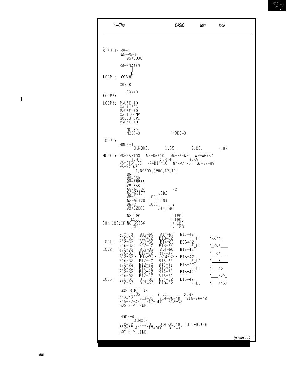
rarily to the regulator’s control input,
which turns on the regulator’s 5-V
output. This 5-V output powers the
three components of the compass-the
LCD, the 2x compass module, and the
processor.
The first thing the processor does is
set an output high which holds the
regulator’s control input high. This
happens before you can remove your
finger from the power switch, allowing
the power to remain on.
PYGMY PROCESSING PROPORTIONS
wanted to use a tiny processor for
obvious reasons. I fully intended to put
a PIC processor directly on the circuit
board. However, I broke down and put
a SIP socket on the circuit board and
wired it to accept a PicStic
1
module,
which already has the crystal and I/O
prewired to SIP pins. This approach
really simplifies the amount of wiring
necessary for the whole project.
The processor initializes the LCD,
asks the Vector 2x compass module for
a bearing, and displays this bearing in
degrees. The LCD uses six output lines
of port B. The first four are data, and
the second two are the control lines.
The data is strobed into the LCD by
the E line. The LCD sees the data as
character or control data depending on
the state of the RS (register select) line.
Of the two remaining bits on port B,
one requests a conversion from the 2x
module and the last bit holds the regu-
lator’s control input high. The PicStic
has two additional bits (port A bits 3
and 4). The compass module has two
outputs which must be read by the
processor, data, and end-of-conversion
outputs. These are wired to the two
bits on port A.
Now all the I/O is used, but two
more functions are needed. It’s time to
share bits.
Since the LCD data is only strobed
into the LCD during an E-enabled
strobe, there’s no problem sharing one
of the data’s output port bits (port B bit
0) with the compass module. This
output bit becomes not only the least
significant bit for the LCD but also the
SCK to the compass that clocks out
the data following a conversion.
The conversion is started by toggling
the P/C line low for
10
ms. The EOC
72
Issue
April 1997
Circuit Cellar INK@
Listing
partial listing shows bow compiled
commands
the main
of fhe electronic
compass program.
LOOP:
IF
THEN SLP
BO=PINS
BO=BO $01
PINS= 0
EPC
'ENABLE VECTOR 2x CONVERSION
PAUSE 10
DPC
CALL CHKEOC
'CHECK END OF CONVERSION
IF
THEN LOOP3
CALL CHKEOC
IF BO=O THEN LOOP2
'GIVE THE VECTOR 2x SETTLING TIME
'GET THE CONVERSION
'DISABLE VECTOR 2x (SLEEP)
CALL CHKSW
'IS THE MODE SWITCH PRESSED
IF
THEN LOOP4
IF
THEN MODE0
IS BEARING MODE
GOT0 MODE1
IF MODE=129 THEN WMODEO
WRITE
WRITE
WRITE
WRITE
:
:
:
'CALC BEARING
READ
: READ
: READ
:
:
:
'GET OLD BEARING
'FIND THE DIFFERENCE
SEROUT
IF
THEN LCD3
'SAME
IF
THEN LCD4
'359
IF
THEN LCD4 '-1
IF
THEN LCD5
'358
IF
THEN LCD5
IF
THEN
'-359
IF
THEN
'1
IF
THEN
'-358
IF
THEN
IF
THEN
'MINUS NUMBER
CHK180: IF
THEN LCD6
GOT0
THEN LCD6
GOT0
LCDO:
LCD3:
LCD4:
LCD5:
:
:
:
:
:
: GOT0
:
:
:
:
:
: GOT0
:
:
:
:
:
: GOT0 LI
:
:
:
:
:
:
:
:
:
:
:
:
:
:
:
:
:
:
:
F-LINE:
READ
: READ
: READ
:
:
:
:
:
GOT0 LOOP
WMODEO:
WRITE
MODEO:
:
:
:
:
:
GOT0
GOT0
GOT0 F LI
GOT0
NE
NE
NE
NE
NE
NE
NE
line drops and remains low until an
EOC occurs. The P/C line may be now
dropped low again to enable the conver-
sion data to be read from the module.
The processor clocks the SCK line
and reads the data the 2x module places
on the
line. When all
16 bits
(32 bits in Raw mode) have been read,
the P/C line is raised, tristating the
output line from the compass.
The reason I mention tristating is
that I share this input with a second
push button. A small pull-up resistor
holds this tristated line high while the
push button isn’t pushed.
Pushing the button pulls down the
line with a smaller but still weak
down so that, if the button is held
down during a compass conversion
read, it doesn’t interfere with the data
driven from the compass.
However, after the compass’s data
has been transferred, the switch can be
sampled for input status because the
compass is no longer driving the line.
This second push button toggles the
compass’s mode. In mode 0, the dis-
play shows the compass bearing. When
Listing
GOT0 LOOP
FOR BO=O TO 7
'8 CHARS TO
LOOKUP
STB
PAUSE 1
STB
'TO LCD
PAUSE 1
NEXT BO
'DO ALL 8
RETURN
LOW 7
GOT0 SLP
'THE CHARS
_CHKEOCCLRF
BTFSC
BSF
GOT0 DONE
GET EOC FROM VECTOR 2x MODULE
_CONV MOVLW
MOVWF
FSR
MOVLW 4
MOVWF
MOVLW 4
MOVWF
CLRF
BCF
PORTB,O
BSF
PORTB,O
; GETS CONV FROM VECTOR 2x MODULE
(continued)
126691
developer kit.... $99.95
l
Low
cost
IBM
PC/XT/AT com-
patible DIO card
l
48
DTL compatible digital
lines arranoed into I-bit
l
Software
for
outputs
l
Emulates 8255 PPI mode 0
Display
136465:
l
4x40 high-con-
trast superlwist
display with unique “big number” mode
prints numerals
l
Pdwer requirement: 5VDC
l
Serial in at 1200,
or 9600
bps
133129:
l
2x16 high-contrast
superlwist display
l
Power requirement: 4.8 to
3mA
l
Serial input: RS232, or inverted CMOS,
at 2400 or
bps
No. Description
136485 4x40 serial LCD display
$159.95
133129 2x16 serial
LCD
Research
14.4
Fax/Data with
Voice
l
V.34 and 14.4 Kbps of data
N
O
.
Price
No. Description
Price
136764
digital
. . . . . . . .
137998
fax/data/voice
FAX:
(Domestic)
FAX:
(International)
E-mail:
EPROM EMULATORS
emulators from $229.00
El
u p t o
E4
up to
l
and 35ns standard access times
l
3V LV models operate at 3V and
l
High-speed downloading
with error checking and correction
l
Loads binary, Mot-S, Intel
l
Power-up emulation
l
Compact size, with protective case
l
Low power design, 5mA max.
l
Software configurable
l
Discounts on
units
Prices
E l - 8 5
$199
$249
E l - 3 5
$229
$ 2 9 9
A - P L C C
$65
SDI
8 0 0 3 5 2
DESIGN
INC.
FAX
i n t e r n e t :
5 2 2 4 B l o w e r s S t . H a l i f a x , N S , C a n a d a
7 4
Issue
April 1997
Circuit
Cellar INK@
Listing l-continued
BCF
BTFSC
BSF
STATUS.0
RLF
DECFSZ
GOT0
MOVF
MOVWF
INDF
INCF
FSR
DECFSZ
GOT0
GOT0
DONE
_CHKSW BTFSS
BSF
B8.7
GOT0
ENDASM
SEE IF MODE SWITCH IS PRESSED
the second button toggles the mode (to
The compass does not have an off
mode the present bearing is stored
switch. Instead, the processor counts
into EEPROM. The display then shows
which direction you must turn to stay
on that particular bearing.
An asterisk alone indicates you are
dead on, and arrows to the right or left
reveal the direction you need to turn
to remain on that bearing. Additional
arrows indicate how far off course you
are. The stored bearing is also displayed
below the arrows.
The processor subtracts the present
bearing from the stored bearing. This
difference determines how many ar-
rows are displayed and in which direc-
tion. A press on the second button
returns you to mode 0, and you again
have a real-time display of the present
conversions and drops the control line
to the regulator, turning itself off if the
second button isn’t pressed within the
time-out period (presently set to several
minutes).
The mode is also saved in EEPROM
when it is switched. This way you can
set a bearing, store it (mode and
romp off toward your first bearing.
Even if the compass shuts off, when
you power it up, you return to the last
mode you were in. You’re immediately
ready to find another bearing point
using the last stored bearing.
FIND YOUR OWN WAY
I hope these articles have started the
bearing.
gears turning in your head. Whether
Figure 2-The four main circuit components include the compass module, processor, display, and power control.
you’re an orienteer, robotics junky, or
just want to build a cool new display
for your car’s dashboard, I think you’ll
have fun with this compass module.
Oh yeah, computations based on
operating current shows this circuit
will run approximately 50 continuous
hours on a standard 9-V alkaline bat-
tery. I think that’s sufficient to get me
wherever it is I’ll need to go-and back
again. Anyone need directions?
q
Bachiochi (pronounced
AH-key”) is an electrical engineer on
Circuit Cellar INK’s engineering staff,
His background includes product
design and manufacturing. He may be
reached at
Vector 2x compass module
Precision Navigation, Inc.
1235 Pear Ave., Ste. 111
Mountain View, CA 94043
(415) 962-8777
Fax: (415) 962-8776
DMC-40448 2 x LCD
America
44160 Plymouth Oaks Dr.
Plymouth, MI 48 170
(313)
Fax: (313) 471-4767
1
microcontroller
Micromint, Inc.
4 Park St.
Vernon, CT 06066
(860) 871-6170
Fax: (860)
Enclosure
8425
Executive Ave.
Philadelphia, PA 19
(215) 365-8400
Fax: (215) 365-4420
MAX833
Maxim Integrated Products
120 San Gabriel Dr.
Sunnyvale, CA 94086
(408) 737-7600
Fax: (408) 737-7194
422 Very Useful
423 Moderately Useful
424 Not Useful
Circuit Cellar
INK@
April1997
75

Not Your
MCU
Tom
easy to overlook the low
end. It’s true that most popular 8-bit
architectures could use a shot of Gre-
cian Formula, so it might appear there’s
not a lot of action to overlook.
I admit desktop machines are fasci-
nating-especially now that high-end
microprocessors, having achieved
supremacy, will be the horses that
carry us beyond the frontiers of com-
puting as we know it.
I’ve heard it said that the PC now
represents 30% of the chip business.
I’m not sure exactly what that means
(e.g., revenue vs. units, just PC boards,
or all the I/O devices as well). But
anyway you cut it, it’s a huge number.
Nevertheless, if 30% is PC, that
means 70% isn’t. And, 8 bits is a big
chunk of that. In fact, though it may
not have the sizzle of the PC biz, I
think the low-end embedded front is
more exciting in many ways.
Whether it’s kinder and gentler air
bags or a self-cleaning kitty box, there’s
no shortage of emerging applications.
However, unless suppliers press on
with ever better chips, it will be hard
to keep up the pace of innovation.
Blessedly for all of us fortunate
enough to work with chips, there’s
always a company able and willing to
prod things along just when a bit-or 8
bits, in the case of the
AVR
family-of excitement is called for.
RISC VS. REALITY
Naturally,
labels AVR a
RISC, a term that has devolved to mean
anything that isn’t an ‘x86 (which itself
is morphing into a RISC anyway).
Nevertheless, AVR adheres to the
original spirit, if not letter, of RISC
more than many. At the same time,
AVR designers weren’t afraid to com-
promise theological purity for the sake
of practicality.
What are the worthwhile lessons to
take away from the RISC revolution?
Here’s my take on the key points and
how AVR measures up.
Much of the impetus for the RISC
was fueled by the desire to move up
from ASM to C. Though I’m not a big
fan of the language, there’s no doubt
that a machine without a C compiler
is hard to sell, so you may as well have
a good one.
This shift, in turn, forced computer
architects to break the ice with com-
piler writers. Lo and behold, the hard-
ware folks discovered all their fancy
instructions and intricate addressing
modes were of little use to a code gen-
erator. Worse, the extra instruction
bloat not only increased the cost of the
chip but limited the speed.
The essential by-product of the new
cooperation between CPU and compiler
designers was the “load/store” machine
with “lots of registers.” These terms
refer to a design in which the only way
to access (slow) memory is by load and
store instructions, while all other
instructions operate only on (fast)
registers, which is why lots of them
are needed.
AVR fully lives up to the basic
tenets of RISC with a load/store archi-
tecture and programmer’s model com-
prising 32 eight-bit registers. For the
most part, the registers are completely
general purpose, one minor exception
being that a few serve double duty as
index registers. Also, operations with
immediates are restricted to the top
half (R1631) of the register file.
Another by-product of the
simple-and-fast philosophy, especially
in the context of pipelining, is that
traditionally featured
length instructions. AVR passes muster
here as well since practically all in-
structions are 16 bits long.
High clock rates and pipelining also
go hand in hand. After all, maximum
CPU clock rate is only as fast as the
quickest pipe stage. However, increas-
ing the pipeline depth and clock rate is
76
Issue
April 1997
Circuit Cellar INK@
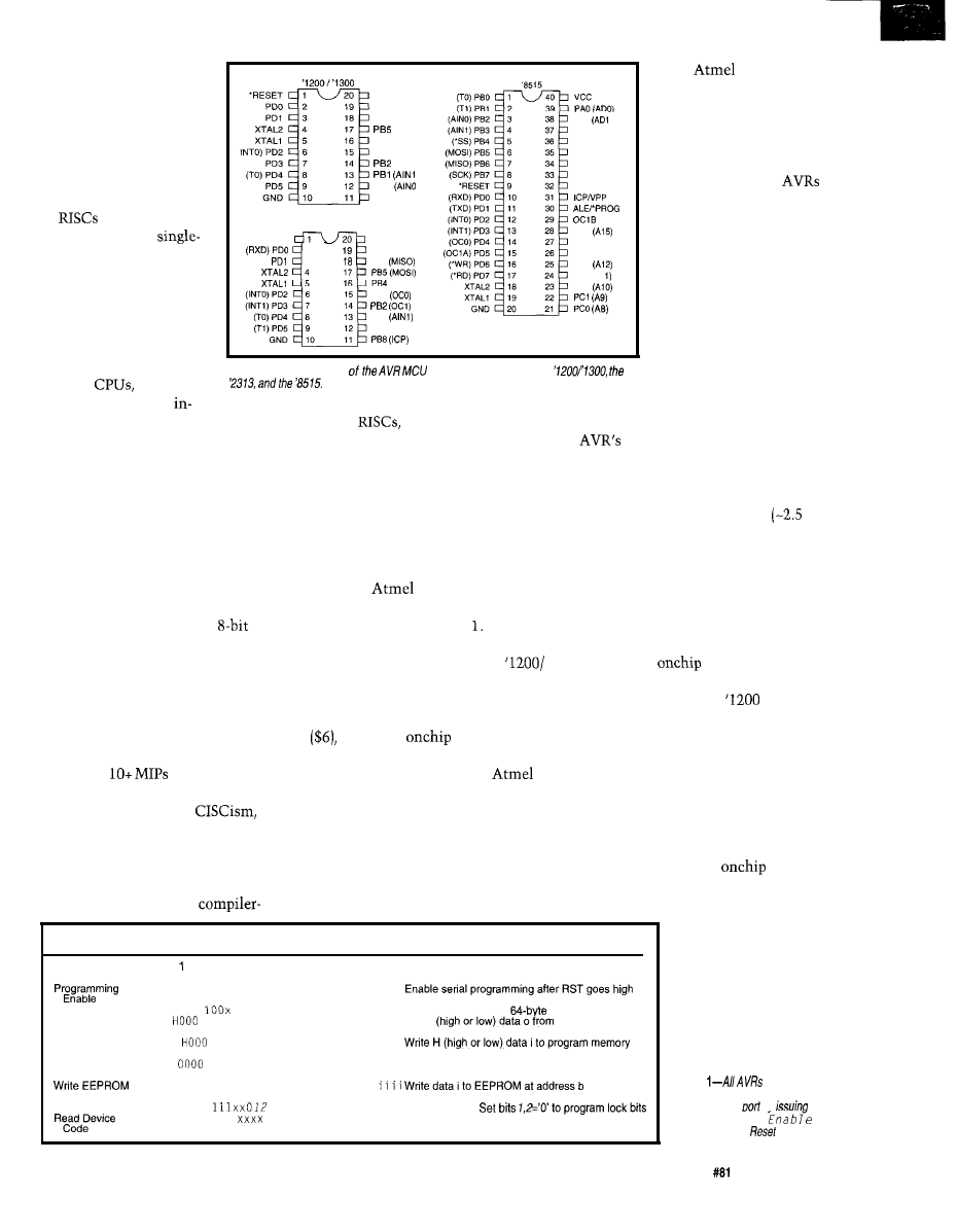
less of a concern (or even a
penalty, given cost and
usability issues) in embed-
ded apps. The AVR com-
promise-a two-stage
pipeline running at up to
24 MHz-seems reason-
able.
are often charac-
terized as offering
cycle instruction execution.
Strictly speaking, this
mainly refers to ALU ops,
with loads and stores,
conditional branches, and
numerics usually taking
v c c
PB7 (SCK
PB6 (MISC
(MOS
PB4
PB3
PBO
PB6
‘2313
‘RESET
VCC
2
PB7 (SCK)
(TXD)
3
PB6
PB3
PBI
PBO (AINO)
PA1
j
PAZ (ADZ)
PA3 (AD3)
PA4 (AD4)
PA5 (AD5)
PA6 (AD)
PA7 (AD7)
PC7
PC6 (A14)
PC5 (A13)
PC4
PC3 (Al
PC2
data,
is one of the
first to offer both. Further-
more, programmability is
accommodated from the
beginning rather than
added on at the end.
For example, all
support both low-voltage
serial programming (see
Table 1) and high-voltage
(12 V) parallel program-
ming. This enables the
designer to combine the
best aspects of in-system
and gang programming,
depending on the particu-
lars of the application.
Similarly, where a
tacked-on EEPROM might
require a slow, complicated driver,
built-in intelligence makes
access easy. The AVR driver is a whop-
ping two instructions long-specify the
EEPROM address and issue a read or
write command. Write timing
ms)
is as simple as polling a bit, while reads
are full speed.
more. Even the fanciest
Figure l--Three versions
have been announced--the
desktop
though able
to dispatch multiple
structions per clock, are hard pressed
centric
which in the interest of
to sustain more than 1 IPC (Instruc-
supporting C, practically force you to
tion Per Clock) for real programs.
use it at all times.
Here, AVR does an excellent job.
With a few minor exceptions, ALU ops
execute in a single cycle, as do untaken
conditional branches. Taken branches
and loads and stores consume two
clocks, with only a handful of instruc-
tions taking more (e.g., the slowest
instruction, RET, is four clocks).
Architecture is well and good, but it
isn’t the only critical factor in typical
embedded applications. Equally impor-
tant are the decisions concerning what
memory and I/O are integrated and
how well they work.
Contrast this with other
chips
penalized by lower clock rates (don’t
forget the marketing megahertz is often
divided down by the time it gets to the
CPU), more (sometimes many more)
clocks per instruction, or both. With
an average instruction probably taking
a mere two clocks or so, AVR delivers
a superior
at full throttle.
Finally, though there’s been a ten-
dency towards creeping
AVR
exhibits admirable restraint in this
regard. The chip has a very straightfor-
ward instruction set that’s notably easy
to program in assembler. The same
can’t be said for desktop
So far,
has announced three
delivery vehicles for the AVR architec-
ture as you see in Figure Given the
CPU’s minimalism, the lineup fittingly
starts with the lean and mean
‘1300 at $1.80 in I k quantities. Adding
a little more memory and I/O gets you
to the ‘2313 for $3. Finally, the ‘8515
puts more
and supports
external memory and I/O expansion.
As with the architecture,
has
done a good job assimilating the best
and brightest memory and I/O features.
In other words, there’s nothing that
hasn’t been done before, but also noth-
ing missing or kludgy.
Though not the first to integrate
flash for program store or EEPROM for
Instruction
Instruction Format
Operation
REDUCED IN SIZE COMPUTER
Photo
1
offers a close look inside
the entry-level ‘1200. Note that the
‘1300 is exactly the same, except it
doubles the
data EEPROM size
from 64 to 128 bytes.
On the surface, the
block
diagram in Figure 2 looks conventional
enough. But, there are more than a few
interesting points worth noting.
For instance, the ‘1200 is more an
in-out than a load-store machine. I/O
functions (including the data EEPROM)
are accessed using separate In and Out
instructions, as shown in Table 2.
Thus, without any
RAM or
external bus, there aren’t many places
to load from or store to. Besides imme-
diate loads, the chip
does support indirect
load and store within
the register file by
Byte
Byte 2
Byte 3
Byte 4
1010 1100 0101 0011 xxxx xxxx xxxx xxxx
Chip Erase
Read Program
1010 1100
xxxx xxxx xxxx xxxx xxxx Chip erase both 1-K and
memory arrays
Memory
0010
xxxx
xxxa
bbbb bbbb oooo oooo Read H
program
memory at word address a:b
Write Program
Memory
0 1 1 0
x x x x x x x a b b b b b b b b i i i i i i i i
at word address a:b
Read EEPROM 1010
xxxx xxxx xxbb bbbb oooo oooo Readdataofrom EEPROM ataddress b
Memory
1 1 1 0 0 0 0 0 x x x x x x x x x x b b b b b b i i i i
Memory
Write Lock Bits
1 0 1 0 1 1 0 0
xxxx xxxx xxxx xxxx Writelockbits.
0011 0000 xxxx
xxxx xxxx oooo oooo Readdevicecodeo
Table
can be
programmed in system via
clocked serial
bv
the
P r o g r a m m f n g
command while
is asserted.
Circuit Cellar INK@
Issue
April 1997
7 7
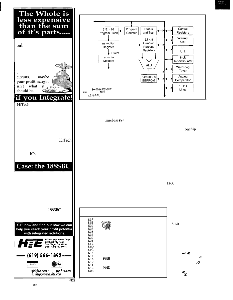
You’re shipping the first systems
the door, the customer is
happy, and you can breath a sigh
of relief now, right? But can you
really afford to relax now?
If that system was
built using many
different boards and
can combine all those
boards and circuits onto a single
board, saving you big money.
Reduce your unit cost with less
inventory and fewer vendors,
faster assembly time, fewer ca-
bles, and even smaller package
size. Built to your specifications,
an integrated board from
can include analog, digital,
FPGA and even custom mixed
signal
all for less money
than your current solution.
One customer needed an x86
class processor with 16 channels
of 12 bit A/D and 8 channels of
12 bit D/A, LCD, Keypad and
Opto-rack interface, two serial
ports, a printer port, real-time
clock, and more. A multi-board
solution would cost around
$1200 each. The
costs
only $749, and includes a power
supply and a custom FPGA!
S i n c e 1 9 8 3
V I A
E-mail: in
Ftp:
We
8-bit Data Bus
Instruction
Register
r
Control Lines
Addressing
Figure
‘1200 combines the
CPU with of code f/ash, 64 bytes of
data
and some handy peripherals.
assigning one register
(R30, also known
However, there are extenuating
as Z) as a pointer to another.
Note the internal oscillator provides
an autonomous
timeout
selections between 16 and 2048 ms) for
the watchdog timer. So, it keeps work-
ing even when the main oscillator is
shut off in power-down mode.
The fact that it runs at 1 MHz seems
like overkill, but it proves handy. The
chip can be configured to run off the
internal clock, eliminating an external
crystal or clock source altogether.
One place the ‘1200 seems to cut a
little deep is the hardware stack. It’s
only three levels, yet it must accom-
modate both hardware interrupts and
CALL and RET instructions. Further-
more, the stack is not accessible via
software (i.e., no PUSH or POP instruc-
tions, not that there’s room to store
much there anyway).
Address Hex Name Function
And, there are only three interrupt
sources-external (INTO, programmable
as
either low-level or positive- or nega-
tive-edge triggered), timer, and analog
comparator. The fact that a ‘1200 pro-
gram is quite small in size (5 12 in-
structions max.) would seem to limit
pressure on the stack as well.
Overall,
I
don’t really have a prob-
lem with the
hardware stack
concept, but
I
wonder if it shouldn’t be
just a few levels deeper. The good news
is the lack of stack activity (only the
PC is saved) translates into a speedy
interrupt response of
only four clocks.
One likely source
SREG Status register
General interrupt mask register
Timer/counter interrupt mask register
Timer/counter interrupt flag register
MCUCR MCU general control register
TCCRO Timer/counter 0 control register
TCNTO
Timer/counter 0 (8 bit)
WDTCR Watchdog timer control register
EEAR EEPROM address register
EEDR EEPROM data register
EECR EEPROM control register
PORTB Data register, port B
DDRB
Data direction register, port B
Input pins, port B
PORTD Data register, port D
DDRD
Data direction register, port D
Input pins, port D
ACSR
Analog comparator control and
status register
of an interrupt is the
timer/counter.
Befitting the minimal-
ist philosophy, the
Table 2
reverts to the
concept of using special and
Out instructions, rather than
memory mapping, for
register access. However, the
instruction set also includes
opcodes set, clear, and
branch on register bits.
circumstances. Most basic is that, with-
out any RAM, there’s no place for a
stack. And, without a stack, a stack
pointer seems superfluous. In fact, the
bigger AVR siblings with
RAM
do have a conventional S P, PUSH, POP,
and so forth.
78
Issue
April 1997
Circuit Cellar INK@
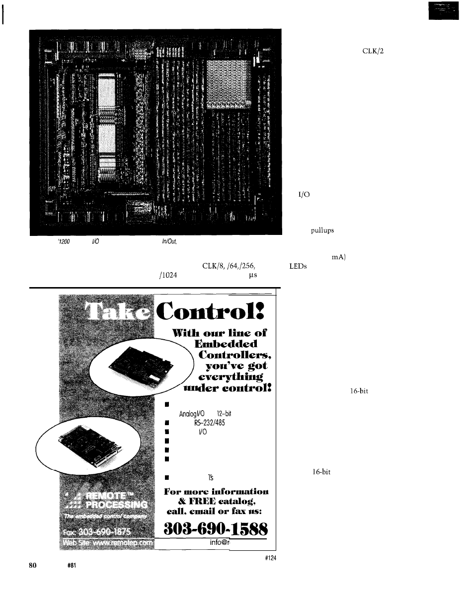
Photo l--The
accesses and memory using separate
rather than load/store, instructions.
unit doesn’t feature a lot of modes and
Internally prescaled clock selections
functions. However, it handles basic
include CLK,
and
duties with speed and versatility.
(i.e., from 50 ns to -50 at
Counter/quadratureencoder inputs
n
8
with
accuracy
Buffered
ports
48 Digital lines
Keypad/display ports
Program with a PC
512K program, 512K data memory
n
Program in C, BASIC, or Assembly
From $195 in
emotep.com
20 MHz]. Alternatively, an external
clock input (with programmable edge
polarity) running up to
can be
connected.
The analog comparator lives up to
its name by comparing the values on
two pins. Its single-bit output can be
read directly or generate an interrupt
when it goes high or low or toggles.
A simple comparator like this can
be coerced into duty as an ADC. One
way is to discharge an RC that ramps a
comparison voltage and measure the
time it takes to trigger the comparator.
Another hack is to generate the com-
parison voltage with a poor man’s DAC
concocted from a PWM output or
external resistor network.
lines not otherwise allocated for
specific use (e.g., comparator, timer,
serial port, etc.) are bit programmable
for direction. In input mode, program-
mable
are offered, as is the
ability to read the output latch or pin.
Rail-to-rail outputs feature high drive
(IOL up to 20
capable of driving
directly.
BIGGER BROTHERS
The ‘23 13 retains the 20-pin form
factor while packing some more mem-
ory and a lot more I/O. Compared to
the ‘1200, both program flash and data
EEPROM capacity are doubled to 2 KB
and 128 bytes, respectively.
The ‘23 13 also includes 64 bytes of
RAM. Besides giving those load and
store instructions something to do, the
appearance of RAM comes with minor
architectural upgrades. These include a
conventional stack,
ADD
and
SUB,
and extra addressing modes (e.g., indi-
rect with displacement, autoincrement,
autodecrement, etc.) which conscript a
few of the general-purpose registers for
x, y, and z index duty.
Besides all the ‘1200 functions, the
‘23 13 goes further on the I/O front by
incorporating some big-ticket peripher-
als. It’s
timer/counter (shown in
Figure 3) has all the options-input
capture (with glitch filter), output
compare, PWM mode, and the like.
There’s also a full duplex UART
with a dedicated baud-rate generator
that can generate standard baud rates
independently of the CPU clock rate.
For instance, the CPU can handle most
Issue
April 1997
Circuit Cellar INK@
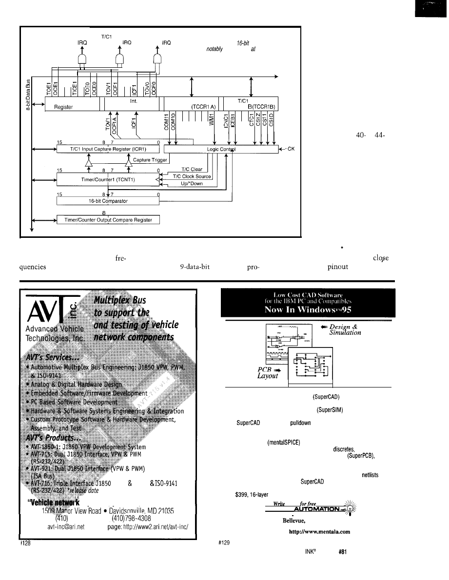
vides a hook for parity
T/Cl Overflow
C o m p a r e
T/Cl Input
Figure
3-Besides a myriad of features, modes,
Match
Capture
and clock options, the
timer/counter on the
checking or multidrop net-
2313 is
fast, running speeds up to the
work addressing, but full
CPU clock rate.
implementation of those
features requires software.
Using the ‘23 13 archi-
tecture and I/O enhance-
ments as a base, the ‘85 15
Timer Int. Mask
Timer
Flag
T/Cl Control
Control
further increases memory
(TIMSK)
Register (TIFR)
Register A
Register
to 8-KB program flash,
256 bytes of data EEPROM,
a
and 256 bytes of RAM.
Switching to a
or
pin (DIP or PLCC) package
enables the larger chip to
support external bus expan-
sion for memory or I/O.
Also, the ‘8515 makes the
SPI (Serial Peripheral Inter-
face) port, restricted to
serial programming duty on
15
7
0
the smaller chips, available
for application use as well.
The bus interface relies
on ALE (Address Latch
standard data rates from 2.4 to
The UART also has false start bit,
Enable) and *RD and WR strobes
115 kbps, at more than a dozen
framing, and overrun detection. It
familiar to 805 1 users. In fact, a
between 1.8432 and 20 MHz.
includes a
format that
look at the ‘8515
shows that it
Products
design
(VPW PWM)
early
1997
expertise, products, and resources”
798-4038
voice,
fax
e-mail:
l
home
l
Easy to use schematic entry program
for circuit diagrams,
only $149. Includes netlisting, bill of materials, extensive parts libraries.
l
Powerful, event-driven digital simulator
allows you to check
logic circuitry quickly before actually wiring it up. Works directly within
the
editor from a
menu and displays results in “logic
analyzer” display window. Starting at $149 this is the lowest cost
simulator on the market. Library parts include TTL, and CMOS devices.
l
Analog simulator
for $149. Allows AC, DC and transient
circuit analysis. Includes models of transistors,
and op amps.
l
Circuit board artwork editor and autorouter programs
starting at $149. Produce high quality artwork directly on dot matrix or
laser printers. You can do boards up to 16 layers including surface mount.
Includes Gerber and Excellon file output. Autorouter accepts
and
placement data directly from the
schematic editor.
l
Low cost combination packages with schematics and PCB design: 2-layer
for
for $649.
or call
demo disks:
M E N T A L
5415 136th Place S.E.
WA 98006
(206) 641-2141
l
BBS (206) 641-2846
Internet:
Circuit Cellar
Issue
April 1997
8 3
can practically plug into an 805 1
socket. This makes sense when you
remember that
has been offer-
ing ‘5
1
derivatives for some time.
The fact the data bus (i.e., ADO-7) is
only eight bits wide may give pause.
However, unlike the ‘5
1,
the ‘85 15
external bus is intended only for data
access, not instruction fetch, somewhat
alleviating bus-bottleneck concerns.
Keep in mind that, also like the
‘51,
the ‘85 15 doesn’t have any WAIT input
or
wait-state generator. Though
it may not be an issue for older, more
leisurely
bus timing is a concern
for ‘85 15s running at higher clock rates.
A memory or I/O chip has to offer an
access time somewhat less than the
CPU cycle time (i.e., under 50 ns for a
20 MHz CPU).
C-U-LATER
There’s always a lag between chip
introduction and broad third-party
support. Meantime,
is covering
the bases with its own emulator and
low-level software tools, as well as a
full-fledged C suite developed by IAR.
Kevword
Description
Function interrupt
monitor
C-task
Variable
sfrb
sfrw
tiny
near
flash
Segment codeseg
constseg
dataseg
Intrinsic
NOP
_LPM
SLEEP
Creates an interrupt function that is called through an interrupt
vector. The function preserves the register contents and the
processor status.
Turns off the interrupts while executing a monitor function
Declares a function as not callable (e.g., main) to save stack
Puts a variable in the
segment (battery-backed RAM)
Maps a byte value to an absolute address
Maps a word to an absolute address
Accesses using 8-bit address
Accesses using
address
Accesses in the program address space
Renames the Code segment
Creates a new segment for constant data
Creates a new Data segment (These are mostly used to place
code and data sections in nonconsecutive address ranges.)
Enables interrupt
Disables interrupt
Inserts NOP instruction
Inserts the opcode of an instruction into the object code
Returns one byte from the program address space
Enters sleep mode
Resets watchdog
Table
addition to
compatibility,
C compiler includes a number of practical extensions as
The tool chain starts with
Windows-based assembler and simula-
tor. The latter gets extra credit for
simulating the operation of interrupts
and
I/O as well as the CPU.
on the company’s CD-ROM
and Web page.
certainly encourages taking a
closer look at AVR with an aggressive
price for these tools-namely, $O!
You’ll find they’re free for the taking
By contrast, the
emulator is
a pricey item intended for
strength development. Based on actual
hardware emulation of the CPU, the
unit delivers hardcore real-time capa-
bilities not found in entry-level tools.
Beyond powerful breakpoint and
RIGEL
Corporation introduces its newest line of boards,
the
Our 8 and
boards
are designed for immediate placement into a
Controller Area Network.
The
features the Siemens SAB
processor, and includes an RS232 serial port, 111
bits,
five 16-bit timers,
system clock, built-in CAN
interface, 4 channels of PWM,
1 MB of
memory
and
of SRAM.
THE RIGEL DIFFERENCE
Assembly,
and Forth.
FOR MORE INFORMATION VISIT OUR WEB SITE
or contact us at
RIGEL Corporation,
PO BOX 90040, GAINESVILLE, FL 32607
Telephone (352) 373-4629
373-l 786
3
PAR (32 BITS MAX)
-32K RAM, EXP 64M
-STANDARD PC BUS
LCD, KBD PORT
BATT. BACK. RTC
IRQO-15 (6259 X2)
6237 DMA 6253 TMR
-BUILT-IN LED
-UP TO 6 MEG ROM
-CMOS NVRAM
USE TURBO
BASIC, MASM
RUNS DOS AND
WINDOWS
EVAL KIT $295
UNIVERSAL
PROGRAMMER
-DOES
6 MEG EPROMS
-CMOS, EE. FLASH, NVRAM
EASIER TO USE THAN MOST
MICROCONT. ADAPTERS
PLCC. MINI-DIP ADAPTERS
-SUPER FAST ALGORITHMS
OTHER PRODUCTS:
8088
SINGLE BOARD COMPUTER . . . . . . . OEM
l 95
PC FLASH/ROM DISKS
16 BIT 16 CHAN ADC-DA
. . . . . . . . . . . . . . . . . . 21 . . . . . 75
C CARD . . . . . . . . . . . . . . . . . . . . .
WATCHDOG (REBOOTS PC ON HANGUP) . . . . . 27 . . . . . 95
‘EVAL KITS INCLUDE MANUAL
BRACKET AND SOFTWARE.
M V S B O X 8 5 0
5
YR LIMITED WARRANTY
FREE SHIPPING
HRS: MON-FRI
EST
a
MERRIMACK, NH
.
(508) 792 9507
84
Issue
April 1997
Circuit Cellar INK@
tion control facilities, advanced fea-
tures include 32 K x 96-bit trace buffer,
time stamp, and software-adjust-
able clock.
Similarly, the C compiler from IAR
is loaded with full ANSI C compatibil-
ity, including IEEE
floating point,
union, enum, bitfield, and so
forth. It costs
for the compiler
only or $2195 with simulator and
source level debugger. DOS and Win-
dows versions are available.
That’s grand, but I suspect I’m not
alone in complaining that it’s often
difficult to figure out how to make C
do simple things [e.g., write an I/O port
or handle an interrupt). Thankfully,
IAR includes a number of handy exten-
sions in this regard, as listed in Table 3.
BEST OF BREED?
Overall, I think it should be clear by
now that AVR is a real dog-and a mutt
to boot! Now, before the folks over at
blow a gasket (or put out a con-
tract), let me deftly extricate myself.
First of all, remember that old say-
ing that a dog is man’s best friend?
Well,
chips are a designer’s best
friend, at least when it comes to whip-
ping up ever-whizzier and more afford-
able embedded gadgets. And from my
experience, a mutt is far more likely to
make a good friend than a persnickety,
bordering-on-psychotic purebred.
Remember that purebreds are, as the
name implies, bred purely for a special
purpose far removed from the owner’s
current application. I mean, how many
sheepdogs actually get to herd sheep?
As well, purebreds all too often seem
to demonstrate the dangers of swim-
ming in a stagnant gene pool.
By contrast, a good mutt combines
the best characteristics of its various
ancestors, while avoiding the worst
excesses. With the speed of a PIC, easy
register-oriented architecture of a
and bit-handling of a ‘5 1, but with none
of these chips’ historical warts, AVR
may be just the doggy in the window
for you.
q
Tom Cantrell has been working on
chip, board, and systems design and
marketing in Silicon Valley for more
than ten years. He may be reached by
E-mail at
by telephone at
657-0264, or by
fax at (510) 657-5441
AVR
Corp.
325 Orchard Pkwy.
San Jose, CA 95131
(408)
Fax: (408) 436-4300
BBS: (408) 436-4309
www.atmel.com
C compiler
IAR Systems
1 Maritime Plaza
San Francisco, CA 94111
(415) 765-5500
www.iar.com
425
Very Useful
426 Moderately Useful
427 Not Useful
l
Robotists and
creations
all over will compete in
this international event
Contestants range
‘college professors&d
rocket
4th
A weekend full of
including a
Robot Fair and Robotics Seminars
Get together
interested people, trade
information,
and HAVE FUN!
Come
for the weekend or come for the
COME AND SEE THE FUTURE!.
For more information and the contest rules,
Mendelssohn at:
or 190 Mohegan Dr., West Hartford, CT 06117
On the Web:
Circuit Cellar INK@
Issue
April 1997
85
INTERRUPT
It’s Win-Win and $10,000
iven my approach to solving design problems, it’s no wonder probably be remembered most for
“My favorite programming language is solder!” While stilt profess it to some extent, the reality
making cost-effective engineering decisions has seriously modified that stance. In fact, these days, it really
o f
gets a
chuckle out of Jeff and Ken when they hear me say, “Just add a little software routine to replace....”
Unless you’ve spent the last 15 years under a rock, you’ve noticed that technology has evolved a couple orders of magnitude.
The simple component-cost tradeoff between using a hardware or software solution isn’t as simple as it once was. Today, the actual
component cost might be secondary to the costs of developing the solution. Everything isn’t as cut and dried as it used to be.
The same is also true of how we choose to cover embedded control designs within the pages of
Just like it would be
remiss of a communications magazine not to acknowledge the significance of cellular technology, we would be ignoring the obvious
not to increase our coverage of PC-based embedded applications.
The reason for the explosion isn’t any conspiracy among programmers. The answer is much simpler. Every engineer has a
PC; it’s only natural to use it.
More and more frequently, the swiftness and cost of development is the primary issue. If asked to quickly produce a I-IO-kHz
sweep frequency generator, hardware people might naturally gravitate toward a couple of hardware oscillators. Software types would
obviously synthesize it using interrupts and counter/timers. Whether they use a PIC or a PC for the latter depends mostly on how
management views delivery and production cost issues. Did I ever tell you about the engineer who was given a day to come up with a
circuit to capture a
serial transmission and store it? He used a
system with
and stored it to flash. The fact that
there might also be a $5 hardware solution (if you have a lot of software-development time available) was considered irrelevant if it
held up delivering the $1.25 million MRI machine for even a day.
Last month,
a new design contest specifically focused on the embedded PC. Probably the most significant
difference between this contest and ones we’ve had before is that there are $10,750 in cash prizes. Even a third-place finish gets you
$2000.
Unlike previous contests, we’ve decided to make this an embedded-PC contest. Picking an
processor (or any of its
variants) as the target platform provides a more even competition. Winning is a matter of design finesse, not complexity. By having
everyone use the same core technology, judges can focus on the merit and scholarship of an entry rather than dealing with the
appropriateness of processor architecture.
The reason this contest has such significant awards is
only due to the support and contributions from the sponsors. They
recognize the significant role Circuit
Cellar
readers are making in the development of computer technology. It is their hope that,
in the process of considering how to take part in this contest, you’ll review their products and perhaps even incorporate them into a
winning entry.
You don’t have to physically build anything to win. Just describe and document the specifics in a way that would enable
someone who had that task to proceed along the proper direction. You don’t have to write the actual code, either. You only have to
describe the logical process and flow required to do it.
This years design contest is a win-win situation. The level of support and commitment invested by contest sponsors is a
declaration of their belief in you as a designer. Successful product designs require efficient engineering. The goal of this magazine, as
always, is to document and promote such accomplishment.
96
issue April 1997
Circuit Cellar INK@
Wyszukiwarka
Podobne podstrony:
circuit cellar1996 04
circuit cellar1991 04,05
circuit cellar2001 04
circuit cellar2002 04
circuit cellar1995 04
circuit cellar1994 04
circuit cellar2004 04
circuit cellar1992 04,05
circuit cellar2000 04
circuit cellar1990 04,05
circuit cellar2003 04
circuit cellar1996 04
circuit cellar1991 04,05
circuit cellar2001 04
circuit cellar1996 04
circuit cellar1992 04,05
circuit cellar1995 04
circuit cellar1997 04
więcej podobnych podstron