
INK
Divide and Conquer
hat’s the best way to approach a large
control or data collection application? You can hit
it with a big hammer and use lots of computing power
in a central location, or you can break the problem into
smaller pieces and spread the load around.
When we designed the Circuit Cellar Home Control System we
opted for the latter approach. We put the burden of deciding when what
happen on one central controller, but we distributed the tasks of
power line interfacing, infrared interfacing, and individual input and output
bits onto other processors spread out around the house.
I’d like to be able to say we purposely followed our Building Automation
issue with a Distributed Control issue because of the HCS II, but I can’t. It
was a coincidence, but a nice one. It gives us the opportunity to point out the
HCS distributed design after having spent an issue talking about its
control capabilities.
THE ISSUE AT HAND
There are many off-the-shelf solutions to distributed control applica-
tions, and Jim Butler gives us a sampling of some of them. Jim has
previously written for
using the nine-bit multipro-
cessor serial format supported by so many of today’s microcontroller chips
In a similar vein, when you have numerous devices that
support
to-point serial communications (usually using
you
often end up with
a jumble of cables and switch boxes that all must be rerouted manually.
Frank Cox shows us how to build an automated switch box using a
conventional chip in a somewhat unconventional way.
Going back to the HCS Steve adds another link to the chain with his
article about the
and its optional people tracking capability. Ed
covers the firmware aspects of the module. I finish up my part of the project
by describing the actual language used to program the system.
In our special section this issue, we talk about the somewhat
ambiguous subject of Embedded Programming. Is that physically program-
ming memory devices for embedded applications, or is it writing code for
embedded applications? We couldn’t decide, so picked articles that cover
both areas
Jeff finishes up his description of the emerging memory card standards
by designing a simple interface that can be used for storing collected data in
harsh environments. Tom gets fuzzy again as we try to decide what he’s
talking about. And, filling in in Practical Algorithms, John Dybowski provides
some hints for making programs that deal with nonvolatile memory more
bulletproof.
The next issue should be dynamite as we look at Real-Time Program-
ming in the feature section and Embedded Sensors and Storage in the
special section.
CIRCUIT CELLAR
THE COMPUTER
APPLICATIONS
JOURNAL
DIRECTOR
Steve Ciarcia
MANAGING
Ken Davidson
Lisa Nadile
ENGINEERING STAFF
Jeff
Ed Nisley
EDITORS
Tom
8 Chris Ciarcia
NEW PRODUCTS
Hat-v Weiner
ART DIRECTOR
Lisa Ferry
STAFF RESEARCHERS:
Northeast
John Dybowski
Midwest
Jon
Tim
West Coast
Frank Kuechmann
PUBLISHER
Daniel Rodrigues
PUBLISHER’S ASSISTANT
Susan McGill
CIRCULATION COORDINATOR
Rose
CIRCULATION ASSISTANT
Barbara
CIRCULATION CONSULTANT
Gregory
BUSINESS MANAGER
Walters
ADVERTISING COORDINATOR
Dan Gorsky
CIRCUIT
INK
4
CT
paid al
CT
additional
U.S.A.
$17.95.
U2.95.
Al
orders
in U.S.
U bank.
orders
PA
a cdl (215) 630.1914.
Cover Illustration by Robert Tinney
to
INK.
P.O. Box
30506,
PA 19396
ASSOCIATES
ADVERTISING
NORTHEAST
SOUTHEAST
Debra Andersen
Collins
WEST COAST
Barbara Jones
(617)
(617) 769-8982
MID-ATLANTIC
Barbara Best
966-3939
Fax:
985-8457
&
Shelley
714) 540-3554
ax: (714)
Nanette Traetow
(908) 741-7744
(708) 7893080
Fax: (908) 741-6823
Fax: (708) 7893082
HST.
2
April/May, 1992
The Computer Applications Journal
14
Embedded Controller Networking Alternatives
by James Butler
22
Infrared Tracking and Remote
Control/Meet the New HCS II IR-Link
by Steve Ciarcia
. .
34
The Frugal Networker/A
Crosspoint Switchboard for RS-232
by Frank Cox
42
Programming the Home Control System II
by Ken Davidson
State Machines in
Software/A Design Technique for Single-Chip Microprocessors
by Peter
Programming the Motorola
by Edward
Editor’s INK/Ken Davidson
Divide and Conquer
Reader’s
INK-Letters to the Editor
New Product News
edited by Harv Weiner
Firmware
Furnace/Ed Nisley
infrared Home Control Gateway
From the Bench/Jeff
Bachiochi
Does it Come With a
Part 2-The Nitty-Gritty
Silicon
Twenty Years of Micros-Now What?
Practical Algorithms/John Dybowski
Writing Code to Support Nonvolatile Memory
from the Circuit Cellar BBS
conducted by Ken Davidson
Steve’s Own INK/Steve Ciarcia
A Night in The Life
Advertiser’s index
The Computer Applications Journal
Issue
1992
Battery Lore Cleared Up
I was just given a copy of
The Computer Applica-
tions
a magazine! In the December 199
January 1992 issue,
contained several
messages addressing camcorder batteries. Boy, what a
mixture of misconceptions! Working in a technical
support position here at Panasonic, I have to answer
these questions day after day. Here are the key points for
the proper care and feeding of your camcorder batteries.
1. Batteries should
following each and
every use! Charge each battery for about 30 minutes past
the point where the charge indicator goes off. No
24-hour
charges!
“Memory” was a condition which supposedly
affected
batteries. Virtually all camcorders today
use lead-acid “gel cell”-type batteries. “Memory” did
have an effect back in the mid 1950s;
technology
has changed drastically since those days. Recently,
several particles have appeared which have basically
written off the entire issue. Battery capacity actually
increased with short cycle discharge/charge cycles.
2. Never store your battery in a partially charged
state. Remove the battery when not in use, as some
camcorders may draw a small amount of power and thus
discharge the battery over time.
3. Exercise the batteries; treat them as you would
your car battery. If you anticipate periods of inactivity,
pop a tape in and let the camcorder run a tape in the play
mode. Recharge the battery immediately after each use!
4. Never discharge the battery to zero. Most
camcorders will shut off at about 10.8 to 11 .O volts. This
is as low as you want to go.
batteries should never
go below 1 volt per cell; going lower will risk cell
reversal and ultimately render the battery useless! Your
camcorder is the best battery
you have-there’s
no need to spend extra money on add-on accessories!
Bob Kozlarek, Secaucus, NJ
How Did She Do It?
I have one question after reading the story of Mr.
Ciarcia’s problem with locking himself out of the house
[The Computer Applications fournal,
issue
How
did Mrs. Picker get over the fence?
I also thought that for systems to be successful, t
hey had to be user friendly. I can assume that Mr.
Ciarcia would have the system activated while he slept.
Did he consider awakening and an emergency run to the
bathroom?
That could be more traumatic than forgetting a key.
But then again, every design has to be tested “in the
field.”
Joe Privitier, Burbank, CA
We’re
talking about a man
who cooks souffle in
dark hooded clothing. We don’t want to speculate on
what his nighttime habits are or, for that matter, those
of his neighbors.
By the way, if you look more closely at the story,
Picker never actually climbed the fence or entered
the backyard. Steve also tells us he‘s already taken
midnight motion by house occupants into
account
in
his system. Editor
Readability Counts, Too
This is a letter that may interest many when it
comes to producing readable code in any programming
language. The first tip describes a method of formatting
equations in programming languages that do not
what you type.
Once an equation is written, it usually becomes
impossible to visualize it. I would like to suggest a
method that I have used to ease the burden of visually
interpreting (and getting the parentheses right when
initially programmed) an equation.
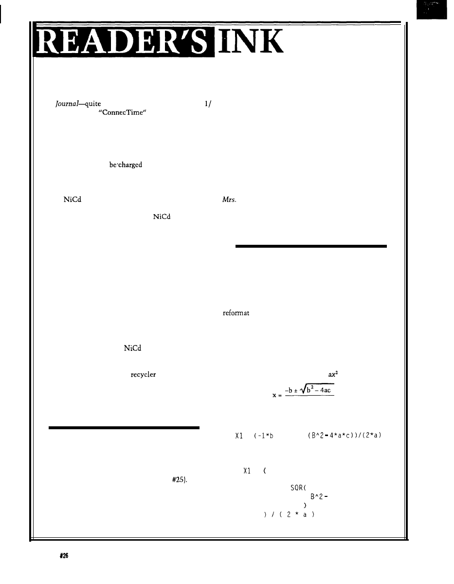
The algebraic form of the equation to find the roots
of the familiar quadratic equation
+ bx + c = 0 is
2a
The usual programming style for one root is
=
+ S Q R
My programming style is
= -b
+
4 * a * c
4
Issue
April/May, 1992
The Computer Applications Journal
Agreed, it uses a lot of white space, but it
doesn’t require a magnifying glass to decipher and
mentally visualize the equation. Note the ease in
which parentheses can be matched.
Another tip is in the use of mnemonic variable
names. Many programmers do not describe what
their short and usually cryptic variable names were
derived from and what their type is. When you are
reading someone else’s program, or your own years
later, it is essential to know the variable type and
the rationale for choosing the name of the variable.
I would like to suggest a comment section in
alphabetical order included in the beginning of the
module that contains the name, type, mnemonic,
and what that mnemonic was derived from. The
alphabetical list allows easy retrieval by the reader.
Example (in FORTRAN):
C
real array
C CURLTH real array
C INIDIA real array
C STAT
integer
of motor)
C
0 stopped
C
1 running
A final thought on comment lines. First there is
the usual style of commenting which includes brief
comments, the description of what the routine does,
and the compiling options. Another style I haven’t
seen used very often can also be useful in some
instances. Describe the current state of affairs at the
instant the comment is read. In other words, what
you have done, instead of what you are going to do.
Information presented this way can sometimes make
it easier for others to modify your code.
Example:
C The routine has now printed
C PROMPT
UNITS
C
where ? was null or the integer VALUE
C if ALDEF was
Ron Dozier,
Wilmington,
DE
Want to Hear from You
readers are encouraged to write letters of praise,
suggestion to the editors of The Computer
Journal. Send them to:
Applications Journal
to the Editor
rk Street
on, CT 06066
16
x
1
3
Characters x
2
line 2 for
40
Characters x
4
line
. . . . . . . . . . . . . . . . . . . . . . . . . . . . . . . . . . . . 32 x 4
. . . . . . . . . . . . . . . . . . . . . . . . . . . . . . . . . . . . . .
24
x
2
line LCD
power
in
BOARD
PC
$79.
dot
entry
7.5
standard telephone interface extension
360 K
Mb
K
1.44 Mb
5.25’
drives
$7
640 200 LCD $29”
he unit is the
the Toshiba
to
o serial
LCD.
POWER SUPPLYS
-5V @
O-O.4 A
@
2
$150.00
Drive
20Mb Hard Drive
40Mb Hard Drive
Non-Enclosed TTL
Comer with
at Amp
Hwhor
15
to do
Black &
7
inch
$29.95
9
inch (Amber) . . . . . . . $29.95
Graphic a Al
hanumeric
Display
Dot
128 Dot, 16 line]
each, or 2 for 20.9
board available $60.00
CONTROLLER CARD BLOWOUT!
pair
IBM
Token network
on. Comes in
kit form
8 0 3 8 7
DC 300 XLP and DC600
These
to
tape cartridges
115.’
125.’
S24.W
Novell Netware
Bar Code
Model HBCR-8300
up
to
60%
off list. Call
version and number of
users you are looking
3Com
$175.00
The Computer Applications Journal
issue
April/May,
1992
5

Edited by Harv Weiner
SOLID-STATE PC FOR
APPLICATIONS
LOW-COST SINGLE-BOARD COMPUTER
The
Solid-State PC
from
Datacom is a
compact, highly reliable device designed specifically for
unattended and embedded applications, such as network
functions, data acquisition, and control.
The Solid-State PC is designed around an AMD 286
processor featuring a clock speed of either 12 or 16
and zero wait states. It features 5 12K of DRAM with
parity, expandable to 4 MB, and provides hardware
support for LIM EMS 4.0. A
flash EEPROM,
expandable to 768K replaces the disk drive.
The Solid-State PC is fully compatible with the IBM
AT bus, but has no conventional keyboard, screen, or
disk drives. The disk drives are simulated by memory,
and a backlit LCD screen plus two general-purpose
button switches are provided for operational use, but can
be disabled if not required. A special BIOS manages the
solid-state facilities, so programs can access them as
standard devices.
A control port and associated DOS software enable a
conventional PC to be attached for software installation,
development, and testing. You can then transfer files
between the conventional disk of the PC and the
state memory. The screen and keyboard of the PC can be
used as if they were peripherals of the solid-state unit.
This feature also allows local or remote monitoring and
of the unit by an appropriate asynchronous device
PC.
In addition to the control port, a standard serial
communication port
and a parallel port
are supplemented by two extra serial I/O ports, which can
operate synchronously or asynchronously. DMA channels
assigned to these ports can provide very fast throughput.
The Solid-State PC features a ruggedized, completely
closed aluminum housing measuring 2.6” x 8.9” x 11.2”.
The absence of a ventilator reduces noise and improves
reliability while permitting use in environments nor-
mally considered unsuitable for a PC. One AT expansion
slot is provided for a card up to 9.4 inches in length.
Optional hardware and software items include a
math coprocessor, ROM DOS, protocol drivers, emula-
tion packages, network adapters, and a communications
coprocessor. The Sold-State PC starts at $1900.
Datacom, Inc.
Peachtree St. N.E., Ste 404
GA 30303
523-l 109
l
Fax: (404) 522-7116
A new single-board
computer, designed for use
as a stand-alone system or as
a user interface to an
existing control system, has
been announced by Applied
Logic Engineering.
The board accommo-
dates a
EPROM for
program storage and a 32K
static RAM for memory
The RS-232 SBC is an
design that
expansion beyond the
includes an on-board 1 x 16
LCD and
keypad to
internal RAM of the
provide you with input and
output capability. The board
Also, the system can be
also includes a full
serial communication port
battery powered by a single
for connections to other
embedded control systems
battery.
or PCs.
Software is provided
on disk for interfacing
with the keypad, LCD,
and RS-232 communica-
tions. A demonstration
program showing the
capability of the board is
included in an EPROM.
Uses for the RS-232
SBC include front ends
for existing control
systems, prototyping,
data collection, testing,
or educational purposes.
The RS-232 SBC is
priced at $109.95.
Applied
Logic Engineering
13008
93rd Place North
Maple Grove,
MN 55369
(612) 494-3704
Fax: (612) 494-3704
moo
8
Issue
April/May,
1992
The Computer Applications Journal
RS232 DATA COLLECTION DIRECTLY
INTO PROGRAM
A program that collects data directly from any
232 serial line, modifies it, and sends it to the keyboard
buffer without affecting normal keyboard functions is
available from Labtronics Inc.
is a TSR that
“tricks” the foreground application program into think-
ing the data was manually entered from the keyboard.
This process takes place transparently in the background
without interfering with the foreground program.
Any
device with a regular data format can be
used.
is especially useful for electronic measur-
ing devices, bar code readers, scales, data loggers, and
portable data storage terminals. Automatically insert
keyboard characters and ASCII codes (macros) before and
after each data field. The effect of these macros is to
press the same keys that would be pressed if the data
were entered manually.
is compatible with any software that
allows data entry through the keyboard. It uses standard
PC serial ports as well as special serial cards. Communi-
cation is bidirectional, allowing commands to be sent to
the instrument for control or to initiate data transfer.
will also run under Windows.
Modify collected data before it is sent to the key-
board buffer or a file.
can use multicharacter
delimiters and filter out nonnumeric data. Data can also
be imported directly from a file. The data will be parsed,
modified, and macros can be added. The data can then be
sent to either the keyboard buffer or another file.
is priced at $145.
Labtronics, Inc.
75
Ave.
Guelph, Ontario
Canada G
(519) 767-1061
SPECTRUM ANALYZER IN A PROBE
The
Model 107 Spectrum Probe from Smith Design converts a standard l-MHz
triggered oscilloscope into a
spectrum analyzer. The probe enables the
scope to display logarithmic amplitude (vertical) versus frequency [horizontal) with a
dynamic range and a selectivity of 0.5 MHz. The scope controls can be used to
provide full zoom facilities on either axis.
The Model 107 Spectrum Probe offers many of the capabilities of a spectrum
analyzer, but at a fraction of the cost. Its usefulness is primarily as a quick diagnostic
and general observation tool in application areas presently requiring use of bench-top
spectrum analyzers and other instruments. Moreover, because the Probe is so small,
you can actually “probe” and explore circuits where you might not do so with a
fledged instrument.
In use, a wide variety of observations can be made. For example, quickly check
amplifier stages for bandwidth, spot undesired resonances, adjust oscillators for
fundamental or overtone operation, probe shielded enclosures or connector
shells for leakage, and test rotating machinery for internal arching.
The Model 107 features a
display range and a low-input capacity, rather than low-Z
input. A
capacitor couples signals to its input, minimizing loading of circuits under test. Maximum input rating is 1000
decreasing to 1 volt at 100 MHz. A
coaxial input adapter is provided. A BNC connector connects the probe to
a scope’s vertical input.
Other specifications include a vertical logarithmic linearity within
a tangential sensitivity of 60
at 50 MHz), with flatness within from 5 to 100 MHz; and low-frequency degradation of about 8
at 1 MHz.
Spurious responses are about -40
with an IF bandwidth of 180
at -3
Horizontal linearity is specified to be
within
The Model 107 Spectrum Probe is priced at $249.
Smith Design
1324
Harris Rd.
Dresher, PA 19025
(215)
Fax: (215) 643-6340
The Computer Applications Journal
Issue
April/May,
1992
9
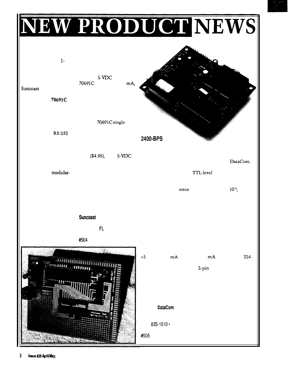
ECONOMICAL 8051 SINGLE-BOARD COMPUTER
A low-cost, 805
based single-board
computer designed for
experimental use has
been introduced by
Technologies.
Completely assembled
and tested, the
computer board contains
the popular 805 1 micro-
controller chip with its
standard 128-byte internal
memory. Also included is
the circuitry for
serial communication
between the 8051 and its
host computer. The
70691 C easily connects to
the host computer’s serial
interface using a standard
four-conductor
type telephone line cord.
The board measures
3.875” x 4.5” and features
a socket for a 2764 8K
outboard EPROM. Four-
teen programmable I/O
ports (sixteen if RS-232
communication is not
required) offer the you a
low-cost computer
engine. The breadboard
area allows customizing
the board for specific
applications.
Operating from a
standard
source, the
draws only 100
allowing the use of the
available prototyping area
for the construction of a
small power supply. An
assembled and tested power
supply is available.
The
board computer is priced at
$38. The unit is available
without the RS-232 inter-
face circuitry for $34.
Options include an interface
cable
and a
power supply ($5.95 without
6-12-V transformer).
Software is available for
writing, assembling, and
converting 805 1 programs,
including a program editor,
assembler, disassembler,
and a hex-to-binary con-
verter.
Technologies
P.O. Box
5835
Spring
Hill, 34606
ON-BOARD
MODEM
A high-speed modem designed for embedded
applications has been introduced by Western
The 224 OEM is compatible at speeds from 300 to 2400
bps, is easy to interface to
serial ports, and is
tunable to support the V.22 and V.21 international
specifications. It features automatic adaptive equaliza-
tion to achieve bit
rates of better than
even
over poor quality lines, and its speed and small size
make it perfect for terminal applications.
The 224 OEM also features FCC-registered direct
connect, DTMF tone or pulse dialing, compatibility with
the “AT” command set, manual or automatic operation,
storage of 32-digit phone number, and originate/answer
operation. Control functions include Abort Timer
Disconnect, Loss of Carrier Disconnect, Long Space
Disconnect, and Failed Call Time-out.
Board placement and connection is simplified with
its compact 3.5” x 2.75” size and power requirements of
volts at 180
(NMOS) or 30
[CMOS). The
OEM DTE interface is a standard 20-pin connector with
standard TTL logic levels. A
0.100” connector is
provided for the telephone line interface. An audio
output is provided if you wish to add an op-amp and
speaker for aural monitoring of the call progress tones.
The 224-OEM Modem is priced at $179. Quantity
discounts are available.
Western
Co., Inc.
P.O. Box 45113
Westlake, OH 44145-0113
(216)
Fax: (216) 835-9146
1992
The Computer Applications Journal
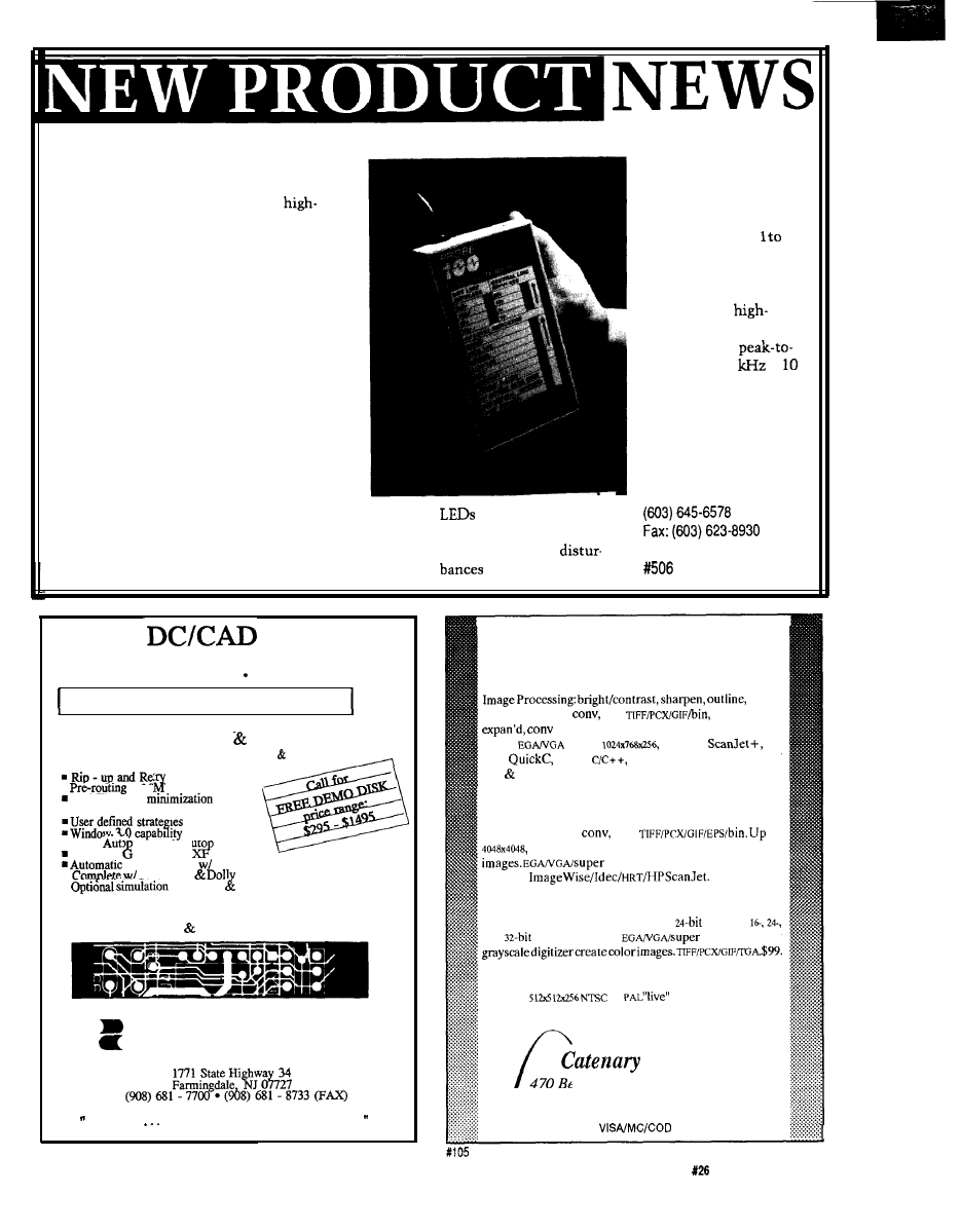
HAND-HELD POWER LINE MONITOR
Random computer
problems such as
software errors, system
hang-ups, rebooting, and
even hardware damage
are often caused by noise
on the AC power line.
Eastern Time Designs
has announced the
availability of the Probe
100, a simple-to-use,
easy-to-understand,
toolbox-sized monitor
that detects and displays
power problems.
The Probe 100
detects a wide range of
power disturbances
including: spikes, sags,
surges, common mode
noise, dropouts, power
failure,
frequency noise,
and wiring
problems. It
reports these
disturbances on an
easy-to-read LED
display.
The Probe 100
is very simple to
use. The unit’s
power cord is
plugged into an
outlet. It immedi-
ately identifies
wiring problems
such as hot and
neutral wires reversed or an
periodically. The
open ground. Then, leave
manual gives a complete
the unit plugged in for 24 to
explanation of the
72 hours, checking the
it can detect.
The Probe 100
detects voltage impulses
on the hot line from 20
to 500 V, and on the
neutral line from
50
V.
Impulses are mea-
sured from their location
on the sine wave. The
sensitivity to
frequency noise on the
hot line is 2 V
peak from 10
to
M H Z .
The
Probe 100 is
priced at $149.95.
Eastern Time Designs, Inc.
2626 Brown Ave.
Manchester,
NH 03103
introducing..
THE TERMINATOR
Super High Density Router
(Complete with Schematic PCB EDITOR)
Features the
following powerful algorithm capability:
.
of S T components
Real-Time via
n
Real-Tie clean up
passes
as DOS
Task
n
1-mil
lacer and Auto arming
Two-way
erber and D
Ground Plane
Cross-Hatching
n
Schematic
Libraries
.
capability protected mode for 386 users
* PCB LAYOUT SERVICE AT LOW COST *
LEASE PROGRAM SITE LICENSE AVAILABLE
Design
Computation
DC/CAD
The focal point of future CAD market
04
IMAGE PROCESSING
Victor Library for C programmers
resize,
overlay, matrix
etc.
use exten’d,
mem, images up to 4048 x 32768 grayscale,
color,
Up to
Lasejet,
for
MSC
,
Turbo
BC++. Includes free copy of
ZIP extensive examples. Source avail. No royal. $195.
ZIP Image Processing software
Bright/contrast, sharpen, outline, noise removal, em-
bossing, matrix
etc.
to
outstanding display and printing of grayscale
VG
A
, LaserJet, dot matrix. Ver-
sions for
Source avail.
ZIP Color-kit
Color reduction software, converts
TIFF
and
and
Targa images to
VGA. Lets any
Frame grabber
Capture
or
video on
V G A
, frame
averaging. With Victor and ZIP Image Processing. $499.
Systems
470
Belleview St Louis MO 63119
Call (314) 962-7833 to order
The Computer Applications Journal
Issue
April/May,
1992
11
REMOTE SERIAL COMMUNICATIONS
CONTROLLER
The Sensor
Modem 500 Series
from
Technology is designed to provide reliable data
acquisition, data logging, or process point control from
a remote location. The unit provides local
485
and wide-area dedicated line, radio, or switched
dial network access for communication with up to 800
digital or analog measurement and control points per
station.
The Sensor Modem is FCC registered,
analog inputs. Expansion I/O modules provide fully
full duplex, and features autoanswering and call progress
isolated I/O in increments of four or eight points, in any
monitoring. DTMF and synthesized voice support used
combination.
both locally and with telephone lines are optional.
The price for the Sensor Modem base unit is $750.
The Sensor Modem is designed around the
Expansion modules run
microprocessor and can address up to 1 MB of memory in
the form of EPROM, static RAM, flash EEPROM,
Technology, Inc.
removable RAM cartridge with battery backup, and OTP
11210
Arrowood Cir.
PROM
program or data modules. The 8.5” x 5.5” x 1.5”
Dayton, MN 55327
base unit requires 12 volts AC/DC at 90
The Sensor
(612)
Fax: (612) 421-9225
Modem comes standard with ten isolated digital inputs,
two relay or driver outputs, and four bipolar
High Performance
Multimegabyte Disk Emulators
NEW MODELS LOWER PRICES
l
Floppy Drive and multimegabyte
emulators for ISA bus computers
l
180K to 14 MB capacities
l
EPROM, Flash or SRAM technologies
l
Autobooting, Single or Dual disk
emulation under PC or MS DOS
l
List prices from $195
CURTIS, INC.
2837 No.
Ave.
l
St. Paul, MN 55113
FAX
PC DOS a trademark of IBM. MS DOS a trademark of
THE POWER OF
Editors Cross Rssemblers Disassemblers
Cross Compilers
l
Data Conversion Utilities
Simulators Serial Communications
R Unique, Universal Development
Communications Environment Supporting
families of
cross-assemblers and compilers.
Communications with your target CPU.
User definable utilities menu.
Pull-down menus with mouse or keyboard control.
PC or compatible.
you can EDIT.
all from mithin ORE,
ERSY
-
TO
-
USE
$99.00 + $2.00 P/H
TO ORDER
LIFE FORCE TECRROLOGY
5477 RUTLEDGE RD.. VR. BERCR. VR. 23464
12
Issue
April/May,
1992
FEATURES
Embedded Controller
Networking Alternatives
James Butler
Infrared Tracking and
Remote Control
The Frugal Networker
Programming the
Home Control System II
Embedded Controller
Networking Alternatives
in
embedded control-
ler networking seems
to be growing rapidly,
perhaps because of the increasing
number of ways an embedded control-
ler network can be implemented. In
this article, I describe several methods
for adding networking capability to
embedded controllers, including
relevant hardware and software
products and standards.
Embedded controller networks,
like office
allow embedded
controllers to communicate with each
other [and potentially with other types
of computers). However, they differ in
their application. Embedded controller
networks are generally used for
distributed control or data acquisition,
whereas office
are used for such
things as file sharing and electronic
mail.
In a typical distributed control
application, each embedded controller
controls a piece of equipment. The
network carries messages containing
controller status information and
level control commands. Frequently,
the source of the control commands
will be some central control station
that constantly queries the status of
the embedded controllers. This central
controller may also allow a human
operator to monitor and control the
entire system.
14
Issue
April/May, 1992
The Computer Applications Journal
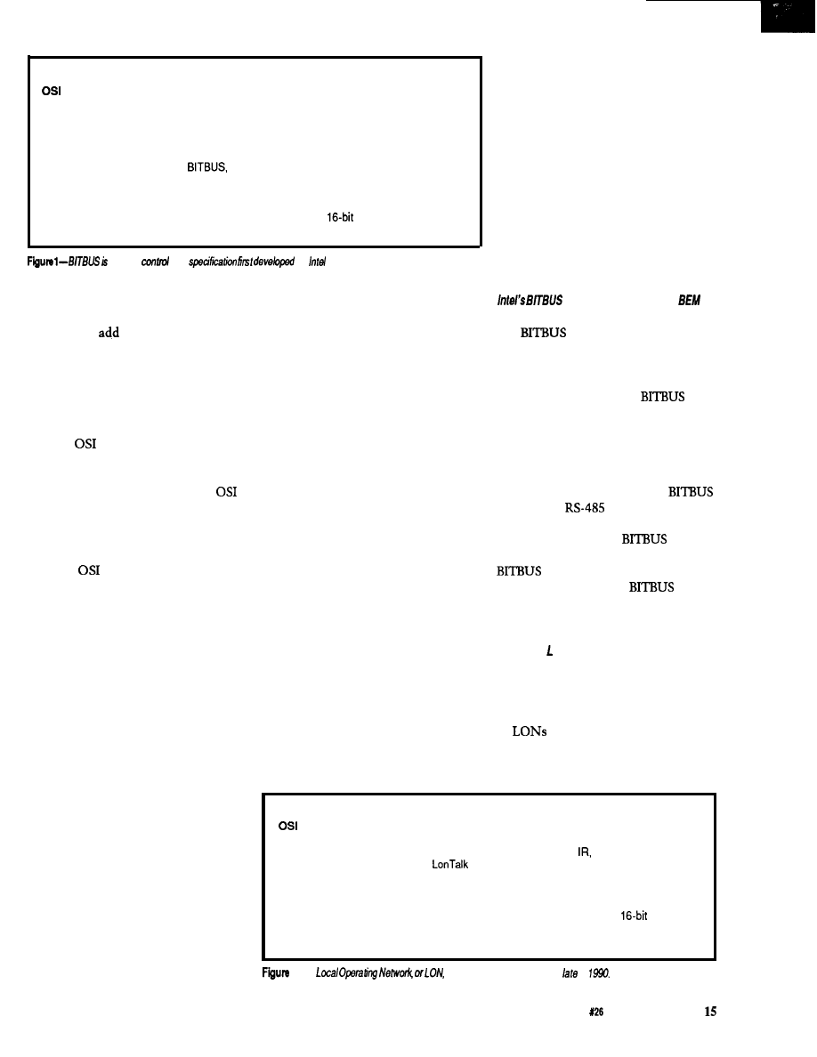
Network nodes:
up to 250 (32 per cable segment)
layers specified:
physical, data-link, application
Electrical specification:
RS-485
cable:
twisted-pair
length:
up to 1200 meters per cable segment
speed:
62.5 kbps, 375 kbps (up to 300 meters), 500 kbps to
2.4 Mbps (up to 30 meters)
Protocol:
based on IBM’s SDLC protocol (open standard)
Transmission:
synchronous serial
Hierarchy:
master/slave
Media access:
controlled by master node
Error detection features:
message acknowledgement,
CRC, sequence count
Application layer features:
data-transfer, task control
a serial
bus
by
in 1984.
METHODS OF NETWORKING
EMBEDDED CONTROLLERS
You can
networking capability
to an embedded controller design using
a variety of methods. Virtually all
require additional hardware and many
also require some software. These
additions implement a network
protocol.
The
seven-layer network
model is often used in the description
of network protocols. Most network
protocols do not specify all seven
layers; for example, Ethernet specifies
only the bottom two layers. Thus,
some network protocols are composed
of two or more protocols that specify
different
layers. Simple networks
may require the specification of only
three layers, which are:
1. The physical layer defines the
physical medium and how message
bits are encoded. It is implemented in
hardware.
2. The data link layer defines
message construction, medium access
control, and low-level error checking
[among other things). It may be
implemented in hardware, firmware,
software, or some combination of
these three.
3. The application layer specifies
high-level network commands as well
as the interface between the network
software and application programs. It
is usually implemented in software or
firmware.
Methods for adding networking
capability to an embedded controller
can be categorized as follows:
1. Use a microcontroller with
built-in networking hardware and
firmware, and add physical medium
interface circuitry.
2. Interface a LAN controller chip
set to the embedded controller, and
add software for the application layer
[and perhaps other upper layers].
3. Make use of serial communica-
tion modes built-in to most
microcontrollers, and add physical
medium interface circuitry and
network software.
4. Interface a serial communica-
tion IC to the embedded controller,
and add physical medium interface
circuitry and network software.
Methods 1 and 2 are hardware
intensive: the network protocol is
primarily or entirely implemented in
hardware and firmware, simplifying
software design. Methods 3 and 4 are
more software intensive, allowing
greater flexibility while keeping
hardware costs to a minimum. Method
3 can often be used to add networking
capability to existing embedded
controllers. I will describe each of
these methods in detail.
MICROCONTROLLERS WITH
BUILT-IN NETWORKING
HARDWARE AND FIRMWARE
The primary advantage of using a
microcontroller with built-in network-
ing hardware and firmware is a greatly
simplified design of embedded control-
ler hardware and software. Unfortu-
nately, there are disadvantages. I am
aware of only two microcontrollers
with relatively complete built-in
network protocols. Also, development
tools for these microcontrollers are
fairly expensive.
solution uses the
8044
microcontroller
is a serial control bus
specification developed by Intel (see
Figure 1). It was first released in 1984,
and has since gained some acceptance
in industrial networking.
nodes generally use an Intel 8044 BEM
microcontroller, which is essentially
an 8051 integrated with a serial
communication controller and
firmware. Each node must also include
an RS-485 transceiver because
specifies an
interface.
Intel offers a wide variety of
development tools for
as well
as distributed control modules.
cards for the PC are available,
allowing the PC to be a
node,
and you can also get board-level
products from other companies.
Echelon’s ON and the Neuron
microcontroller
Echelon [Palo Alto, CA) intro-
duced its Local Operating Network
(LON) in 1990. Echelon suggests that
its
(see Figure 2) could be used
in a wide range of distributed control
environments, such as automobiles,
Network nodes:
many
layers specified:
all
Communication media:
twisted-pair (1.25 Mbps or 78 kbps). RF (4880 bps),
power line (9600 bps), coax,
optical fiber
Protocol:
(proprietary)
Transmission:
serial
Hierarchy:
none (peer to peer)
Media access:
predictive CSMA, optional CD, optional priority
Error detection features:
message acknowledgement (optional),
CRC,
message ordering, duplicate detection
Application layer features:
network variables
2-The
was introduced by Echelon
in
The Computer Applications Journal
Issue
April/May, 1992
Network nodes:
OSI layers specified:
Communication media:
cable length:
Protocol:
Transmission:
Hierarchy:
Media access:
Error detection features:
up to 255
physical, data link
92-ohm coax, twisted pair, optical fiber (2.5 Mbps)
up to 20,000 ft separation between farthest nodes using
standard timings
(open standard)
serial
none (peer to peer)
token passing
message acknowledgement,
CRC
Figure
was
introduced in 1977 by
and has
a de facto standard
factories, and buildings. For a more
complete description of Echelon’s
LON, refer to Ken Davidson’s article
in
Circuit Cellar INK.
The
microcontroller embodiment
of the LON nodes are the
designed Neuron chips (manufactured
by Toshiba and Motorola), which
integrate a microcontroller and data
communication hardware implement-
ing a proprietary seven-layer network
protocol
Transceivers
handle the interface between Neurons
and the communication media.
Neurons are programmed using
Echelon’s Neuron C. Echelon claims
the features of Neuron C (including
network variables), and other
Builder development tools, make the
development of distributed applica-
tions simpler, faster, and cheaper.
Development tools are available
from Echelon, but the price may be a
barrier to some; the
starter
kit costs $17,995 (lease options are
available). Neuron chips cost about
$10 each in large quantity, but the
chip makers project the price will fall
to about $5 in 1993. As of January,
1992,
Transceivers were not
available. Echelon will be selling
media interface modules or they will
provide technical data from which you
can design your own. LON interface
boards for desktop and industrial PCs
are also available.
LAN CONTROLLER CHIP SETS
Another way to add networking
capability to an embedded controller is
to include a LAN controller chip set.
Chip sets are available that interface to
a wide range of microprocessors and
some microcontrollers.
This approach is advantageous
because you can construct a moderate
to high bandwidth network while
using industry-standard protocols. The
main disadvantage is the chip set is
likely to increase the cost of your
controller hardware significantly.
Another disadvantage is, regard-
less of the chip set you choose, you
will probably have to write software
that implements an application layer
(high-level network commands) of
your own design as well as having to
write microcontroller code to talk to
the chip set.
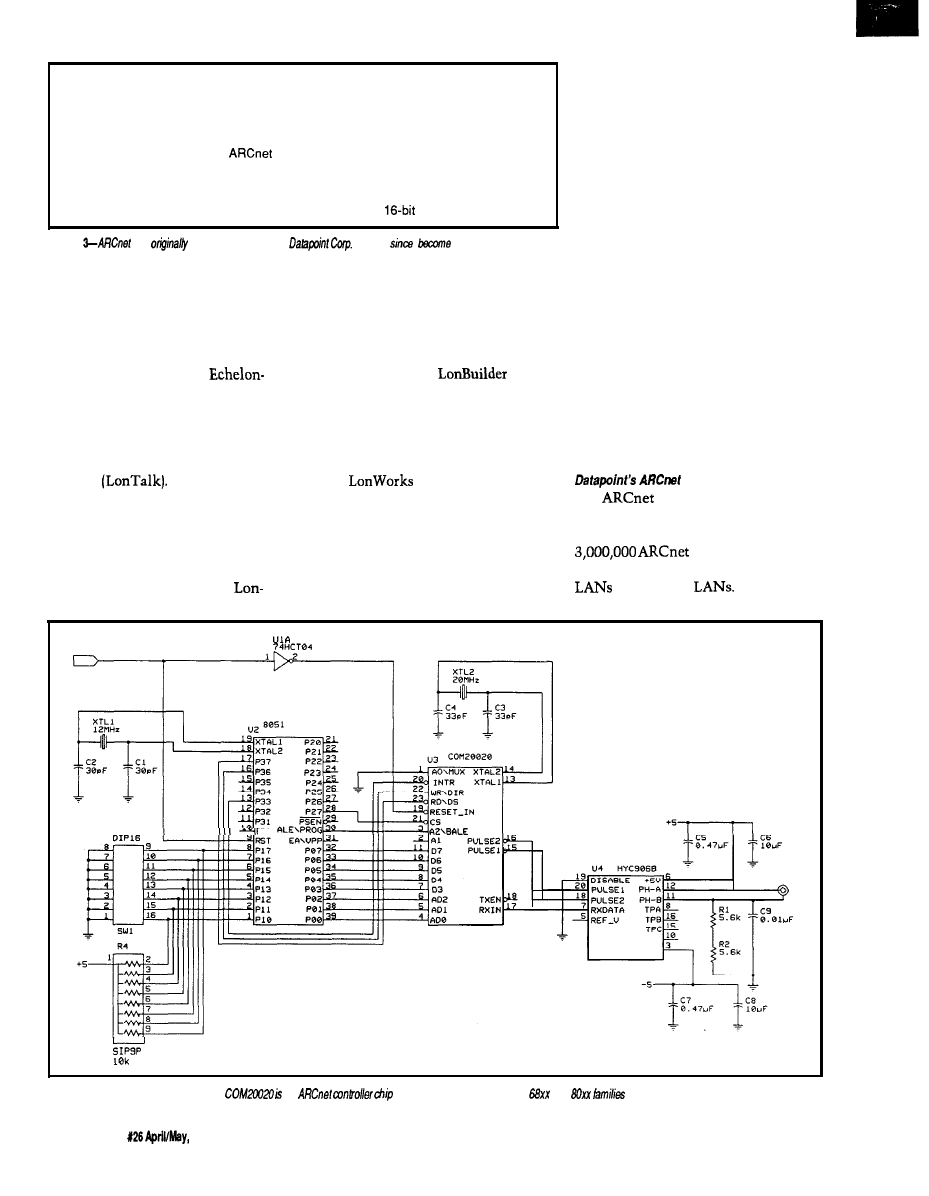
was originally introduced
in 1977 by Datapoint Corp., and has
since become a de facto standard. Over
nodes have been
installed in everything from industrial
to office PC
R E S E T
P 3 0
Figure 4-The
Standard Microsystems
an
designed to interface with the
and
of microprocessors.
16
Issue
1992
The Computer Applications Journal
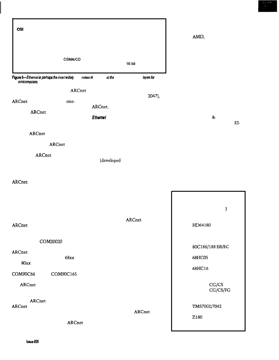
Network nodes:
many
layers specified:
physical, data link
Communication media:
50-ohm coax or twisted pair (10 Mbps)
cable length:
up to 1500 m separation between any two nodes on one
network
Protocol:
Ethernet
Transmission:
serial
Hierarchy:
none (peer to peer)
Media access:
Error detection features:
message acknowledgement (optional),
CRC,
sequence count
used
and
In the office LAN market,
competes with Ethernet. Although
has a data rate only
fourth that of Ethernet, the perfor-
mance of
can be comparable
to or even better than Ethernet in
certain situations. Of particular
interest to embedded systems design-
ers, each
node is guaranteed
access to the network within a known
length of time, and
can out-
perform Ethernet for short messages.
Adding
capability (see
Figure 3) to an embedded controller
design will typically require three
packs: a controller IC, a media inter-
face hybrid, and glue logic. The
controller will handle the
transmission and reception of mes-
sages, but the software running on the
microcontroller will be responsible for
formatting messages to send and
interpreting received messages.
These days, the most active
marketer of silicon-implementing
appears to be Standard
Microsystems Corporation
(Hauppauge, NY). The Standard
Microsystems
($16.23
each in 1000 quantity) is a 24-pin
controller chip designed to
interface with the Motorola
and
Intel
families of processors
[Figure 4 shows an example). The
and the
are
good for Intel 80x86-based designs.
interface cards are
available for the PC, allowing you to
put PCs and embedded controllers on
the same
network. Vendors of
board-level products include
Standard Microsystems and Ziatech
(San Luis Obispo, CA).
Datapoint is working on
Plus, which promises higher speed (20
solution
data-link and physical
PCs
Mbps), longer messages (up to 4096
bytes), and more nodes (up to
as
well as downward compatibility with
Ethernet is perhaps the most
widely used network solution at the
data-link and physical layers for PCs
and minicomputers (see Figure 5).
Ethernet has also been promoted for
factory automation by companies like
DEC. The original Ethernet specifica-
tion
by Xerox, Intel, and
DEC) was used as the basis for IEEE
standard 802.3, which has a slightly
different message format.
Ethernet has the highest data rate
of any of the solutions I describe (10
Mbps), but it may also be the most
expensive solution for you. Ethernet
performs best when transmitting long
messages under light to moderate
traffic loads. Unlike token-passing
protocols, such as
and IEEE
802.4, an Ethernet node can get
immediate access to the network if
there are no messages currently being
transmitted. However, Ethernet is not
deterministic: there is no upper bound
on how long it may take for a network
node to gain access to the network.
Ethernet chip sets are usually
designed to interface with micropro-
cessors rather than microcontrollers.
Adding Ethernet capability to an
embedded controller design typically
requires two or three packs plus
microprocessor bus interface circuitry.
The Ethernet controller will handle
the transmission and reception of
messages, but as with
the
software running on the microproces-
sor will be responsible for formatting
messages to send and interpreting
received messages. Ethernet chip sets
are manufactured by several compa-
nies including Intel, National Semi-
conductor,
Philips-Signetics,
and Standard Microsystems.
Ethernet interface cards are
available for the PC, allowing you to
put PCs and embedded controllers on
the same Ethernet network.
MICROCONTROLLERS WITH
BUILT-IN SERIAL
COMMUNICATION MODES
For applications in which hard-
ware cost must be minimized, you
should consider designing a network
that makes use of serial communica-
tions capability, which is built into
virtually all common and 16-bit
microcontrollers as well as a few
bit devices. A popular communication
medium is twisted-pair cable, to which
the microcontroller is interfaced using
an inexpensive RS-485 transceiver like
the 75176.
This approach has some potential
limitations. The network bandwidth is
moderate, typically 57,000 to 375,000
bps. You have to write or purchase the
software implementation of a network
protocol. Finally, the communication
Microcontrollers with 9-bit
asynchronous serial communica-
tion capability (partial list
Hitachi:
Intel:
805 1 family
8096
Motorola:
family
68HC 11 family
68300 family
National Semiconductor:
COP884
COP888
HPC family
Texas Instruments:
Zilog:
family
Super8
18
April/May, 1992
The Computer Applications Journal
Network nodes:
up to 32
layers specified:
physical (W-485) data link, application
Electrical specification:
(RS-485)
cable:
twisted-pair
length:
up to 1200 meters
speed:
9600 bps
Protocol:
proprietary
Transmission:
asynchronous serial
Hierarchy:
master/slave
Media access:
controlled by master node
Error detection features:
message acknowledgement (optional),
checksum
Application layer features:
data transfer
Figure
the connection
of
and
embedded
boards and a PC.
processing overhead can be significant,
depending on the protocol you use and
the amount of network traffic.
Asynchronous
serial
communication
Most microcontrollers with
in serial communication capability
have
that can be used for
networking.
network protocol that makes use of
bit multiprocessor modes, refer to my
article, “A Simple RS-485 Network,”
Two techniques have been used to
reduce asynchronous serial communi-
in Circuit Cellar INK, issue
cation processing overhead, and most
microcontrollers can make use of at
least one of them. Intel’s
multi-
processor mode reduces communica-
tion processing by using the ninth bit
of each
character to indicate the
beginning of a message, the first
character of which is the node address.
Motorola’s technique uses an idle line
to delimit messages. Of the two
techniques, Intel’s is found in more
microcontrollers, including Motorola’s
more recent parts (see sidebar). If you
are interested in the description of a
Many people who construct
asynchronous serial networks write
their own network software. However,
at least two companies are offering
microcontroller software for asynchro-
nous serial networking. Micromint
Inc. (Vernon, CT) offers network
software that allows the connection of
Micromint’s
and
embedded controller
boards and a PC (see Figure 6).
Cimetrics Technology (Ithaca, NY)
offers software toolkits for embedded
controller networking, which support
several microcontroller families (805 1,
and
and the
PC. Their NSP protocol allows the
master network node to read from and
write to slave node memory and I/O
ports (Figure 7).
Synchronous
serial communication
stop bits for synchronization, instead
Synchronous serial communica-
tion differs from asynchronous serial
communication by not using start and
synchronization information is
extracted from the data stream. As a
result, synchronous communication
Network nodes:
up to 250 (32 per cable segment)
OSI layers specified:
physical (RS-485 recommended), data link, application
Electrical
(W-485)
cable:
twisted-pair
length:
up to 1200 meters per cable segment
speed:
depends on microcontroller, 62.5 kbps typical
Protocol:
NSP, an adaptation of IEEE 1118
Transmission:
asynchronous serial
Hierarchy:
master/slave
Media access:
controlled by master node
Error detection features:
message acknowledgement (optional),
CRC,
sequence count
Application layer features:
data transfer
Figure
7-The
mode
supported by many popular microcontrollers is the basis of
Technology’s
INTERFACE
TO
AR-16 RELAY INTERFACE
89.95
Two channel relay output ports are provided for
control
to
16 relays (expandable to 128 relays
using EX-16 expansion cards). Each relay output port
connects to a relay card or terminal block. A
of
relay cards and relays are stocked. Call for more info.
RS-422 available (distances to 4,000 feet). PS-8 port
selector may be used to control satellite AR-16
interfaces (up to 16,384 relays).
RD-8
REED RELAY CARD (8 relays)
S 49.9:
RH-8 RELAY CARD (IO amp
277
EX-16 RELAY EXPAN. CARD (16
D I G I T A L
BIT
ADC-16
(16
8 bit)
$ 99.95
Input temperature, voltage,
pressure,,
energy usage. energy demand. light levels,
movement and a wide variety of other types of
signals. Inputs may be expanded to 32 analog or 12
status
using the AD-16 or ST-32
cards. 112 relays may be controlled using EX-16
cards. Analog inputs may be configured for
temperature input using the TE-8 temperature input
conversion. RS-422 available. PS-8
selector may
be used to connect satellite ADC-16
(up to
4,096 analog
status inputs and 14,336
relays). Call for info on 10 12 bit converters.
[terminal block and cable sold separately)
ST-32 STATUS EXPAN. CARD (32
Input
status of relays, switches, HVAC
thermostats, security
smoke
and thousands of other devices.
isolators sold separately)
TEMPERATURE INPUT CONV 49.95
Includes 8 linear IC temperature sensors.
Temperature range is minus 78 to 146 degrees F.
TONE DECODER and other serial interfacing
available. Call for free information packet.
FULL TECHNICAL
telephone by our staff. EACH ORDER INCLUDES A
FREE DISK WITH PROGRAMMING EXAMPLES IN
BASIC, C AND ASSEMBLY LANGUAGE. A detailed
reference manual is also included.
. HIGH
for continuous 24
hour
applications. All
socketed.
Use with IBM and
Tandy, Apple and
most other computers with RS-232 or RS-422 ports.
All standard baud rates
protocols may be used
to 19,200 baud).
Use our 800 number to order FREE INFORMATION
PACKET. Technical information (614) 464.4470.
24
HOUR ORDER LINE (800) 842-7714
Visa-Mastercard-Ameiican Express-COO
ELECTRONIC ENERGY CONTROL, INC.
360 South Fifth Street, Suite 604
Columbus, Ohio 43215
The Computer Applications Journal
Issue
April/May, 1992
19
uses network bandwidth more effi-
ciently. Industry-standard protocols
that use synchronous serial communi-
cation include HDLC (IS0 standard
4335) and SDLC.
A few microcontrollers have
synchronous communication capabil-
ity appropriate for networking includ-
ing the Intel 8044 (similar to the 8044
BEM previously mentioned in the
section), the Zilog
18 (a
variant), and the National Semi-
conductor
These chips
have hardware that assists you in the
implementation of the HDLC- or
SDLC-like protocols. Detection of the
beginning and end of messages, address
recognition, O-bit insertion, and CRC
computation are common features.
You will have to implement upper
protocol layers in software, and
depending on the microprocessor you
choose, you may also have to imple-
ment some of the data-link layer.
Microcontroller-peripheral networks
Another common serial communi-
cation feature on microcontrollers is a
clocked synchronous serial communi-
cation subsystem for communication
between microcontrollers and periph-
eral chips over a small area (typically
within a controller or appliance). This
feature can allow chips to communi-
cate using just two or three connecting
wires.
One of the most popular serial bus
specifications is the Philips-Signetics
bus, a two-wire multimaster serial
bus capable of up to 100 kbps. In
addition to
peripherals and
microcontrollers, Philips-Signetics
offers
chips that allow some
PC components to communicate on
an
bus.
SERIAL COMMUNICATION
A few microcontrollers and most
microprocessors lack built-in serial
communication capability. If you
intend to use such a processor, you
may be able to add a serial communi-
cation chip to your design at a cost
significantly lower than adding an
or Ethernet chip set [described
previously].
The use of a serial communication
IC has the same disadvantages as the
use of microcontrollers with built-in
serial communication features.
Namely, this solution requires a
software implementation of a network
protocol.
One feature to look for in serial
chips is the presence of
which
can reduce the probability of lost
characters and reduce communication
processing time. One popular serial
communications controller with both
asynchronous and synchronous
capability is the Zilog 28530 (the
recommended chip for AppleTalk
hardware). For asynchronous commu-
nication, I have had good results with
the National Semiconductor
and Intel 825 10
both of which have
LOOKING AHEAD
At this point, the list of adopted or
emerging standards relevant to
embedded controller networking is
expanding. In addition to the standards
I’ve already described, the four
9
7
Cool. No fan required.
Use it to build:
Embedded video games. process
testing instruments.
controllers,
multi-racked computers. any embedded
or tiny
computers
case
holds floppy hard
disks. this
two halt cards).
Fully functiil
with standard
motherboard peripherals
clack,
included.
External 12V
supply included.
Single evaluation units: S
ea.
Competitive quantity pricing.
Computer Innovations Since
Order
No Risk Satisfaction guaranteed
Tech (214)
FAX (2 14)
13410
Rd., Dallas, TX 75240
20
Issue
April/May,
1992
The Computer
Applications Journal
1111
tioned below may have significant
impact on embedded controller
networking. Industry-specific stan-
dards are also being developed.
CEBus is an emerging home
automation standard that has been
under development for the last several
years. Interested readers can refer to
three previous Circuit Cellar INK
articles for details (see references).
CEBus hardware is beginning to
appear; Intellon Corporation (Ocala,
FL) recently introduced a power-line
modem IC capable of communication
at 10,000 bps.
IEEE 1118 is a recently approved
standard for a serial control bus based
on the
protocol. However, I
am not aware of any products other
than
products that are IEEE
1118 compliant at this time.
General Motors adopted MAP
(Manufacturing-Automation Protocol]
in order to allow the networking of
GM’s numerous
and robots.
Subsequently, MAP was adopted by
several other large corporations. At the
lower protocol layers, MAP was based
on IEEE 802.4 (token bus) and 802.2.
MAP has the reputation of being very
expensive to implement, which has
certainly slowed its acceptance.
is an emerging ISA [and
IEC) serial communication standard
for the networking of low-level devices
in an industrial setting.
IN CONCLUSION...
International standards for
embedded controller networking have
been slow to develop, and some will
eventually have a large impact. But as I
have demonstrated, the large number
of hardware and software components
available make the construction of
practical embedded controller net-
works possible today.
q
Jim Butler is a software engineer at
Cimetrics Technology. He received
B.S. and M.S. degrees in engineering
from M. I. T.
401
Very Useful
402 Moderately Useful
403 Not Useful
The
Interconnect Serial Control
Bus Specification,
Intel Corporation,
1988.
Ken Davidson, “Echelon’s Local Operat-
ing Network,” Circuit Cellar INK, issue
“Connecting with Neurons,” Embedded
Systems Programming,
Sept 1991.
“Choosing a network for local industrial
control,” EDN, Nov 24 1988.
Chip Tackles Real-Time
Embedded Control,” Electronic Design,
Nov 8
1990.
“The deterministic character of
proves ideal for the factory floor,” EDN,
Sep 15 1988.
Token Bus Network: Technical
Overview,”
Trade Association
(Arlington Heights, IL).
“The Return of
BYTE,
Feb
1991.
“Ethernet: Ten Years After,” BYTE, Jan
1991.
David Flint, The Data Ring Main: an
Introduction to Local Area Networks,
Wiley
pub., 1983. Good Ethernet
information; also a good general reference
on networks.
Jim Butler, “A Simple RS-485 Network:
Exploit the Nine-Bit Serial Communication
Modes of the 805 1,
and 2180 Microcontroller
Families,” Circuit Cellar INK, issue
Ken Davidson, “CEBus Update: More
Physical Details Available,” Circuit Cellar
INK,
issue
Ken Davidson,
A New Standard in
Home Automation,” Circuit Cellar INK,
issue
Weiner,
“New Product News:
CEBus Power Line Interface Products,”
Circuit Cellar INK,
issue
“The Best LAN May Be Found off the
MAP,” EDN, Nov 7 1991. Also mentions
Ethernet and
An Emerging Communications
Standard,” Microprocessors and
Microsystems,
1988.
Ken Davidson, “Domestic Automation:
CEBus Goes Coax,” Circuit Cellar INK,
issue
Get Byte-BOS”
and leave
the
MULTITASKING
to us!
Why spend months designing, documenting, coding, and debugging a
multitasking kernel when you can have Byte-BOS, a widely used
multitasking operating system on your desk tomorrow?
Byte-BOS Multitasking Operating System consists of a complete set of
integrated multitasking components including a robust kernel, “add on”
libraries, and development tools that run on a PC.
Only
$995
b ys our multitasking kernel with all these features:
preemptive
scheduling
resource management
task management
application
user
event management
c compiler
message management
royalty c source
timer management
1 year of tech support
Add these multitasking libraries to suit your application:
“on chip”
manager
multiple message buffer manager
manager
multiple timeout manger
block memory manager
dynamic task manager
Develop
and debug Byte-BOS applications on a PC with these tools:
for target
multitasking debugger
Byte-BOS is available for a wide range of microcontrollers and
the PC.
Our technical support is responsive, friendly, and knowledgeable. Call us
today and see how easy multitasking can be with Byte-BOS.
Integrated Systems
PO
Mar
CA
800-788-7288 or
The Computer Applications Journal
Issue
1992
21

Infrared
Tracking
and
Remote
Control
Meet the New
HCSII IR-Link
Module
Steve Ciarcia
ver since I built
(presented in
‘85
one of the improvements I’ve wanted
to incorporate into any new HCS was
an ability to extend control of the
system by remote means. After all,
these days I can sit on the couch with
one IR remote control and command
an entire audio-visual surround sound
entertainment system.
By now you know that the new
HCS II is a reality (see
for more
information). While it contains
noteworthy enhancements over the
original, the physical solution to
producing some of these features was a
far cry from the initial design tech-
nique. IR remote control was a prime
example.
During the design phase I ap-
proached the task of adding remote
control by looking for an off-the-shelf
IR remote control chip that could
easily interface to the HCS. Since IR
remote control chips usually come in
encoder/decoder pairs, I assumed the
proper route would be to use the
encoder chip to make a hand-held
device with buttons (as if you really
needed another IR remote) and use the
decoder chip [with suitable IR recogni-
tion circuitry) wired to the HCS as the
receiver. Press a coded key on the
transmitter and presto, the code is
received by the HCS and acted upon.
Ed, Ken, and I had already speci-
fied the basic configuration of the new
HCS and its networked COMM-Links.
The X- power line controller
(designated the PL-Link) was already
up and running. The IR-Link was to be
the next module on the system.
My initial proposal designated the
Motorola MC 145030 as a suitable
remote control encoder/decoder chip
[see Figure 1). An added bonus was
that the MC145030 contains both an
encoder and decoder, eliminating the
need for two separate chips.
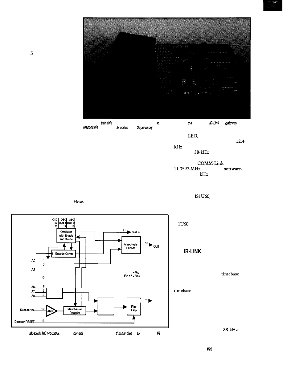
The MC145030 encodes and
decodes 9 bits of information (512
combinations). The chip Manchester
encodes the selected address input and
sends the information (twice) serially
out via the Encoder Out pin (pin 16).
The transmission frequency of this
data is determined by an RC oscillator.
This frequency can be up to 500
but, for reasons Ed and I will explain
later, I chose 12.4
Sending a
command therefore takes 5.16 ms.
I quickly threw together the
circuit in Figure 2 to test the concept.
This simple three-chip circuit takes
the Manchester-encoded serial output
and modulates it with a
square
wave (selection of the modulation
frequency depends on IR receiver
used). This signal then controls a pair
of IR
through a FET. Press
transmit and everything is automatic.
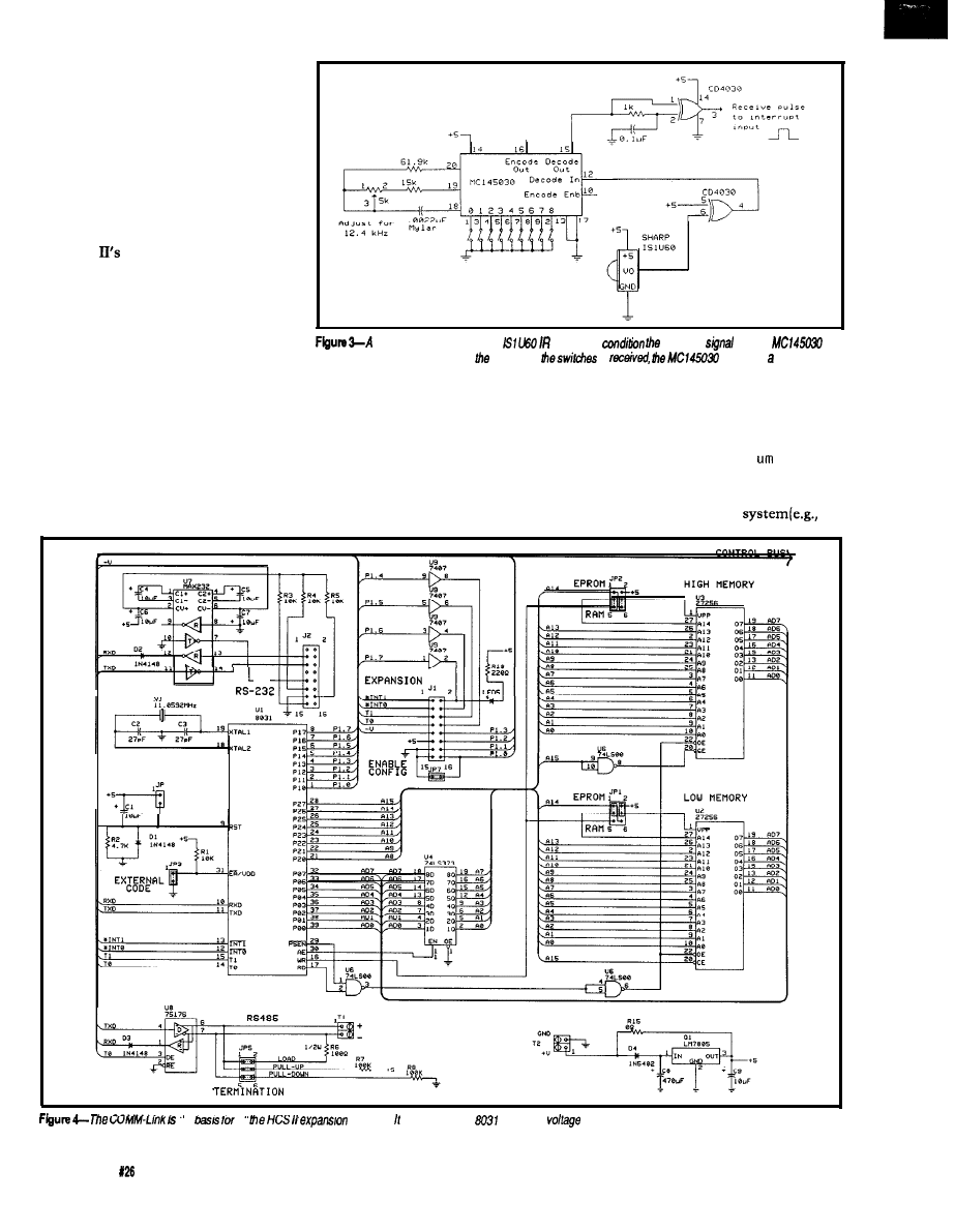
The receiver circuit, shown in
Figure 3, is even less complex. The
IR signal is received and demodu-
lated through a Sharp
IR
receiver chip. Its output is inverted
and connected to an MC145030, which
is configured this time as a decoder.
When the specific
code selected
on its address inputs is received, the
MC145030 generates a “code received”
signal that can be easily connected to a
processor interrupt.
OK, LET’S START THROWING
STUFF OUT
It took about three nanoseconds to
realize that adding a serial decoder
chip to a processor is like putting a
saucer under a coffee cup. You only
need it when you rock the boat.
In computerese, this translates to
mean having the decoder chip is
redundant. Given the low data rate
involved, the decoding function can be
completely simulated in software. All
we need is to connect the
IR
receiver directly to the processor and
add a little fancy “Nisley stuff.” The
added advantage of receiving it totally
22
Issue
April/May, 1992
The Computer Applications Journal
in software is that the 9 bits
transmitted can now be com-
pletely used as data. Rather than
designate a single address confir-
mation, as the hardware unit
does, the 9 bits can be used to
designate 12 codes for ID badges,
optical keys, hand-held remote
corn-mands, and so forth. Any
way you can transmit the
Manchester code, the IR-Link
could now receive and process it.
Back at the transmitting end
we now had a different problem. I
wanted everyone to utilize the
new IR-Link for remote control,
but I had a lot of trouble justify-
ing the fact that we’d have to
supply a costly hardware trans-
mitter to use it.
Photo l-Any
held-held remote may be used send commands to HCS Il. The
is a
for directing
to the
Controller.
While I was mulling
over
this
obvious production problem, testing of
the basic elements continued. To
eliminate changing jumpers every time
I wanted a different code, I bought a
trainable IR controller at Radio Shack
and trained it with a dozen or so codes.
Rather than change jumpers or add a
keypad encoder to the prototype, I now
just used the “trained” remote.
the Manchester-encoded IR signals
without actually using an MC 145030,
then we could use a trainable remote
and eliminate the cost of making a
unique hardware transmitter.
lightning to strike this time. I used a
physical circuit containing the encoder
chip to create the signal source.
ever, if we had some way to simulate
Well, it took four nanoseconds for
an IR LED controlled by a processor
output bit and a software routine.
The obvious answer was that if
Ed and I discussed the possibility
the IR-Link processor could decode the
of indeed reducing the transmitter to
serial data, it could also generate and
encode it. In effect, the transmitter
could be reduced to nothing more than
just an
but some practical
limitations intervened. While a
data rate was easily accommo-
dated, the
modulation fre-
quency was not as easily synthesized.
Because the
uses an
crystal, the
generated 38
could not be pro-
duced exactly on frequency. In fact, it
could be off by as much as 1.5%.
When you look at the specifica-
tion of the
this frequency shift
does not appear to degrade perfor-
mance, but given some of the physical
tests I performed, I think some of their
specifications are optimistic. The
IS
is an extremely good IR
receiver but is also a narrow-band re-
ceiver. As soon as you move off fre-
quency, the sensitivity rapidly drops.
E n c o d e r 1 0
Enable
E n c o d e r
Al
4
A3 5
3
-
r
A4
Address
A 5
, G e n e r a t o r
Pin 14
15
Decoder
Address
T o g g l e
O U T
Comparator
Figure l-The
a remote
encoder/decoder chip
up 512 unique
codes.
THE
HARDWARE
To complicate matters, transmis-
sion frequency is only part of the
equation. A trainable remote also uses
a processor and internal
to
sample and reconstruct IR waveforms.
It is also susceptible to the same
errors described above. If we
synthesize a signal with a certain
error, and then sample and regenerate
it with more error, we could poten-
tially move out of the bandwidth of
the IR receiver again.
To eliminate error sources from
our end, I put a hardware
oscillator on the IR-Link board. The
The Computer Applications Journal
Issue
April/May, 1992
2 3
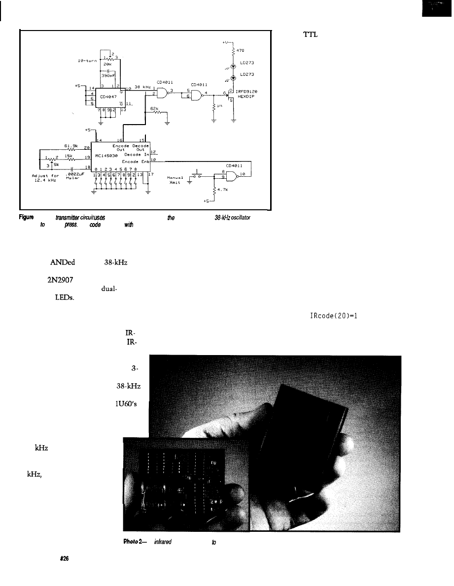
2-A basic
the MC145030
to encode
data and to gale a
in
response a button
The
sent is set
a bank
of switches.
software still encodes and creates the
serialized Manchester data, but from
there it is
with the
signal to produce the modulated
signal. A
transistor pulses a
pair of single-element or a
element IR
The schematic of
the 803 1 -based COMM-Link circuitry
(explained in the last issue) is shown
in Figure 4. Figure 5 outlines the
additional circuitry specific to the
Link. Photo 1 shows an assembled
Link board.
Finally, in viewing the schematic,
some of you might ask why I have a
volt LM317 regulator in the circuit. I
have already suggested that the
modulation frequency is critical. A
shift in frequency affects the IS
receiver’s response, and hence the
distance over which the IR-Link could
receive commands. A remote
control sending a coded signal
at 38
will be received at a
much greater distance than
one sending the same code at
39
for example. After
going through so much effort
to reduce training errors,
frequency shift in the oscilla-
tor itself had to be minimized.
A CD4047 oscillator chip
with polycarbonate or mylar
clock source. However, the major
error-causing influence is the power
supply voltage. Set the oscillator when
the supply is at 4.9 V, then use it at 5.1
V and there will be a frequency shift.
To minimize power supply variations,
the CD4047 chip has its own regula-
tor. Since we can’t know what voltage
will be used to power the IR-Link (5 V,
or 9-12 V, even possibly up to 35 V),
the LM3 17 operates from the 5 V
supplied to the other chips (3 V is still
a valid
switching level]. As a
result of the regulator, the frequency
should stay the same during calibra-
tion or use.
The final IR-Link design did away
with the hardware encoder/decoder
chip and synthesizes the Manchester
codes in software. Ed describes the
command set in his article, so I won’t
duplicate the explanation here other
than to reiterate our design approach.
Like the other HCS II COMM-Links,
the IR-Link is intelligent and designed
for both independent or network
operation. As an independent periph-
eral connected via RS-232, the IR-Link
adds IR code-activated control and
recognition to any PC.
BADGE READERS AND
PEOPLE TRACKING
The
idea behind the IR-Link is to
use a trainable hand-held IR remote
controller like the one you might
already be using with your TV and
have it contain 10 or 20 of these
control codes. Simply aim the remote
at the IR-Link and the code will be
received by the HCS II’s Supervisory
Controller (SC). Within the SC’s event
repertoire, you might have
IF
THEN
Exhaust_Fan=ON
END
or
capacitors is a relatively stable
The
ID badge, the key the people tracking system, is no larger than a small pager
24
Issue
April/May, 1992
The Computer Applications Journal
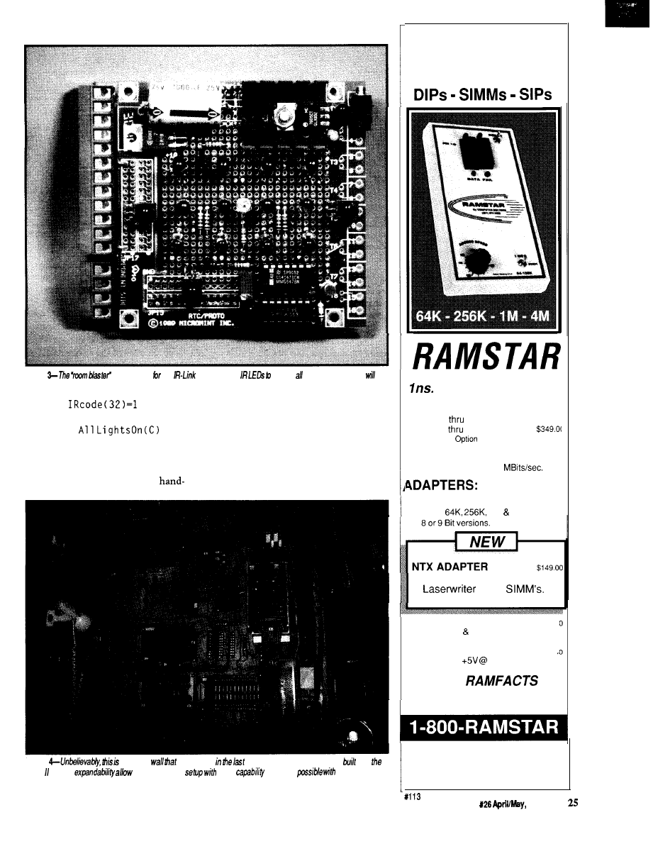
Photo
“interface
the
uses multiple
ensure badges in the mom
hear the transmission regardless of their orientation.
IF
THEN
held remote control can actually do
Alarm_Bell=ON
quite a bit.
As easy as the concept might be to
END
synthesize the IR-Link functions in
software, I still found it difficult to
Given 512 codes and the intelligent
give up soldering something. Having
programming of the SC, your
the ability to network together enough
Photo
the same
was shown
issue. The additional features
info
HCS and ifs
a much cleaner
more
than was
he original
HCS.
FAST COMPLETE
ACCURA TE
DRAM TEST
RESOLUTION
ACCESS SPEED VERIFICATION
80
ns.
180 ns. (Std.)
5249.01
45 ns.
110 ns. (Fast)
4MEG
Add $ 89.01
AUTO-LOOP
Continuous Test 6.25
SIMM/SIP ADAPTER
$189.01
Tests
1 M 4M Devices
Tests 64 Pin Dual-Edge
Type
4 X ADAPTER
$
89.01
Tests 64K 256K By 4 Bit Devices
AC ADAPTER
$
18.0’
Regulated
1 Amp.
FREE
DRAM NEWSLETTER
COMPUTERDOCTORS
9204-B Baltimore Boulevard
College Park, Maryland 20740
MADE IN U.S.A.
U.S. PATENT No. 4.965.79
The Computer Applications Journal
issue
1992
IR-Links to cover a whole house or
office and only use it for IR remote
control seemed especially strange.
Not that I have any great ambi-
tions to deal with a computer as if it
were another person, but home control
system software can be greatly
personalized if the system has a
“special” program that runs when it
“knows” you are there. For example,
the HCS
normal control program
might be simply to turn a table lamp
on in the solarium when someone
enters the room (sensed by a motion
detector). However, if after 5
P
.
M
.
it
identifies that I am the person entering
the room, rather than just turning on
the one lamp, it could make my hard
day at the office a faded memory as it
turns on the table lamp, dims it to
half, and then switches on and dims
the lights over the bar as it queues the
stereo and CD player. All I need now is
the automatic martini maker [a serious
consideration).
basic receiver uses a Sharp
receiver to
incoming
and the
to
decode it When the code matching
one set on
is
generates
pulse.
This scenario can be extrapolated
that a control program can be tailored
even further if we suggest that as long
to an individual person is valid. On the
as the system could identify me and
SC, the event sequence starts with:
which location I am in, it could
channel the music to follow me as I
IF Steve=Sol
ari
roamed about.
Of course, this might seem an
where “Steve” is defined as a specific
extreme example, but the suggestion
IR response code to the
R E S E T
me
all
modules. is based on the
and has a
regulator on the board so can be run from a range of
power supples.
26
Issue
April/May, 1992
The Computer Applications Journal
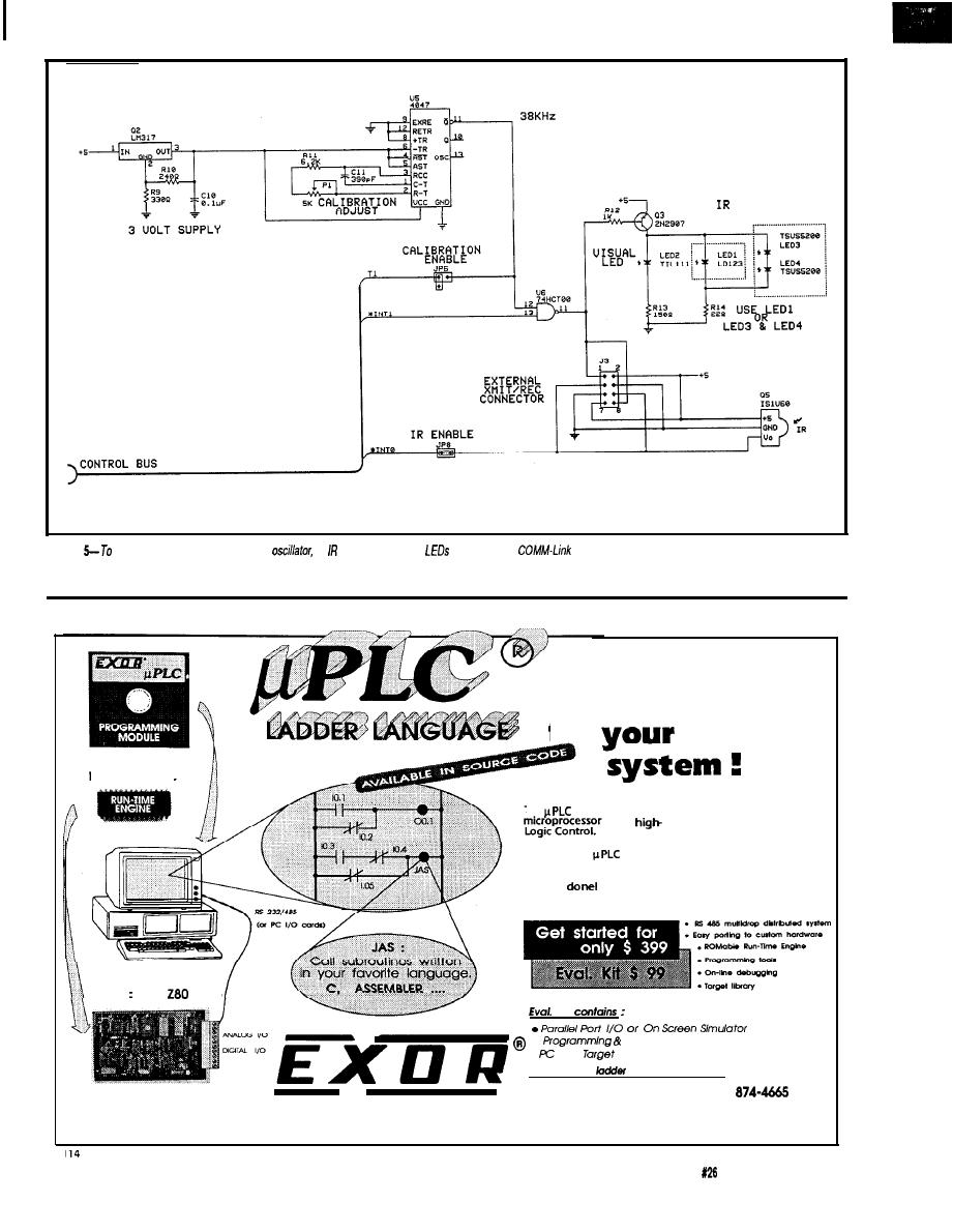
LEDS
IR RECEIUER
Figure
make an /R-Link bard, just add an
an receiver, and some
m
the base
board.
LADDER LOGIC
The basic
building block
for
control
The
operating system kernel trasforms your basic
into a
performance Programmable
CPU’s 8051
8086
YOUR EMBEDDED CONTROL SYSTEM
E L E C T R O N I C
R & D
Just plug the
ROM into your favorite microprocessor
card, load the integrated programmer/debugger onto your
PC, connect a serial cable and begin taking the credit for a
job well
Kit
l
Debugging
modules
.
TSR
Excellent for
language training
FAX (513) 874-3684 CALL (513)
4850 Interstate Dr. Cincinnati, OH 45246
The Computer Applications Journal
Issue April/May, 1992
2 7
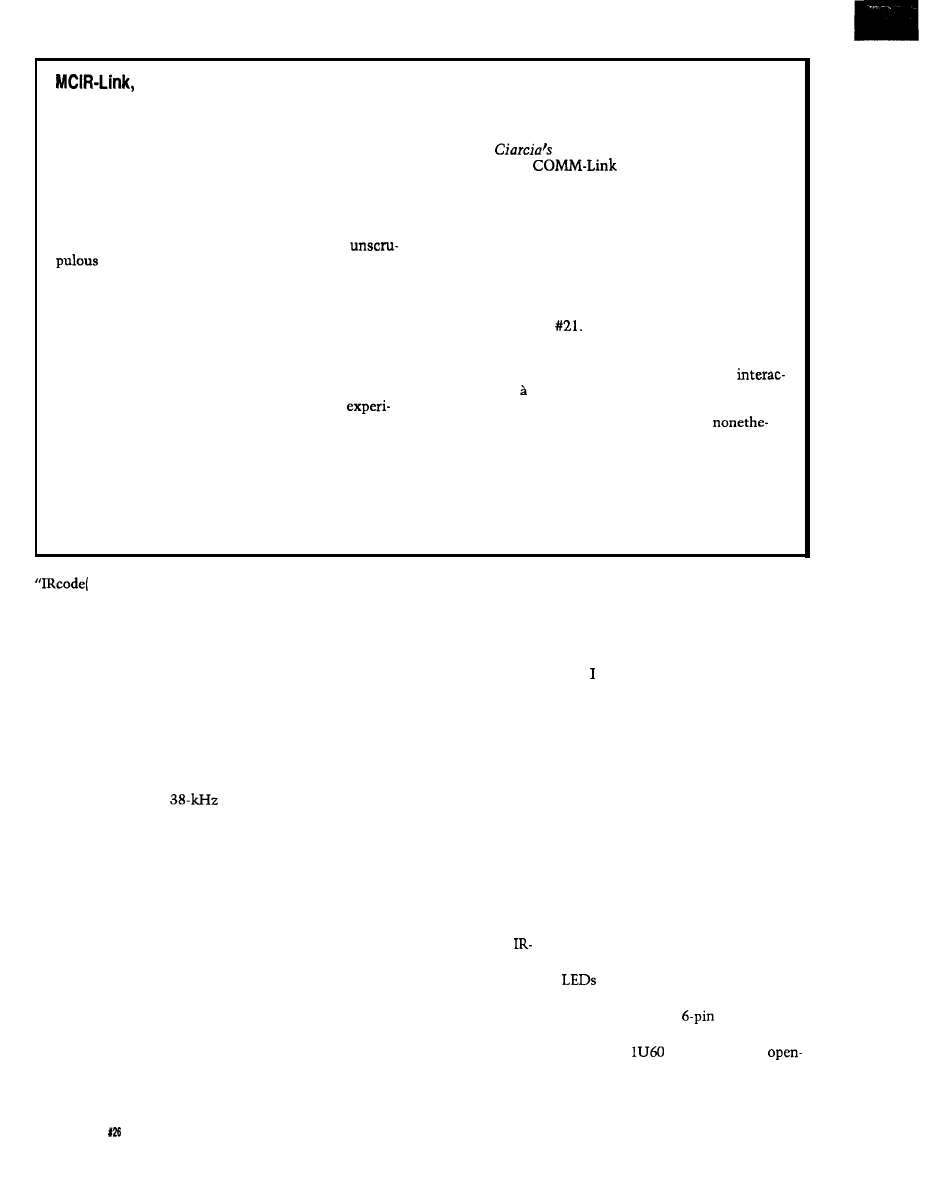
TIM-Link, and...TREK-Link?
Generally speaking, we at
Circuit Cellar INK
like to
First of all, Ed and I are going back and resurrecting
be remembered for our achievements, so we rarely
the Master Controller Trainable Infrared unit (published
speculate and try not to discuss “vapor” hardware or
in
Best of
Circuit Cellar,
chapter 32) and
software. Unfortunately, the immediate success of the
attaching it to a
node. After training the
Circuit Cellar HCS II has caused quite a number of you
Master Controller [using a PC) with all your hand-held
to ask about other COMM-Links beyond those presently
remotes, the Supervisory Controller can then command
available.
any individual or series of stored IR sequences to be
Our policy has always been to design and build
transmitted. This capability makes it possible for the
interfaces before announcing them. Too many
HCS II to, for example, cue up a specific CD or tape and
businesses float “vaporware” before actually
set the appropriate volume in response to you walking
producing anything. However, we are often guilty of
into the room.
sitting on a design until all the pieces are complete
Second, Ken and I want to build an updated version
before we present it.
of the Touchtone Interactive Monitor (TIM) system that
A certain compromise may be in order. The success
I presented in issue
We recognize the need for
of the HCS II deluged our offices with questions about
outside interaction with the HCS, and a more intelligent
pending designs. Our merely answering, “No” to the
and articulate version for TIM is our goal.
potential existence of other COMM-Links could give
Finally, all of us have discussed a true voice
you the impression that the HCS II is a dead-end design,
tive interface, la the
Enterprise’s
computer from “Star
rather than a continuing vehicle for high-tech
Trek.” I still think the concept has more entertainment
mentation among the Circuit Cellar engineering staff.
than control value, but the idea is intriguing
By breaking precedence and telling you our plans, I
less. Unfortunately, this idea is one that is still waiting
risk discussing vaporware in my effort to satisfy reader
for technology to advance to a point where there is a
demands. However, given this caution, combined with
cost-effective solution. How long this module remains
the understanding that any projects I mention here are
on the drawing board depends on such an evolution.
still just ideas and that my describing them does not
So I ask you to bear with us while we take some
mean they will be automatically published as design
time before delivering these designs to you. After all,
projects, let me outline some future plans for HCS II.
we’d like them to work first.
IO)“) and “Solarium” is
system “knows” both the identity and
unfeasible were it not for the unique
defined as the number of the IR-Link
located in the solarium (e.g., “2”).
When the condition is true, a list of
actions will be performed. The only
concern is finding a cost-effective
method to identify an individual.
While possibly suited more for an
office than the home, our solution was
to use an electronic ID badge. We have
already described that the IR-Link’s
primary function is to sit passively and
monitor the ether for
Manchester coded IR transmissions.
Take the circuit in Figure 2, add a
lithium battery, replace the manual
transmit switch with a slow 0.1 -Hz
oscillator, and build it into a small
pocket-clip container. Every 10
seconds this portable beeper transmits
a coded signal just like you were
pressing the button on a hand-held
remote. Provided it is aimed in the
vicinity of an IR-Link (more about
increasing coverage later), the SC will
receive that transmission as it would
any other. By selecting a unique code
for each badge (different from those
reserved for remote control) the
28
Issue April/May,
1992
The Computer Applications Journal
the location of an individual.
Of course, as with any asynchro-
nous transmission method like this
one, if too many badges are in the
same area, there can be message
collisions. The solution is to use an
“intelligent” badge like that shown in
Figure 6. In this circuit, each badge has
a unique code
(1
of 5
12)
set by the
jumpers on the MC 145030. The badge
is designed to transmit only after it
receives its own code.
Using the IR-Link, we “poll” a
particular area by sending out specific
badge codes. When the badge receives
its code, the circuit waits 25 ms and
then sends back the same code. When
the IR-Link receives this return
transmission, the system then knows
the location of that ID badge. The
Link has built-in commands to
facilitate polling an individual badge or
complete ranges of badges.
To prove the concept was feasible,
I built one of these intelligent badges
into a package that is the size of a
small pager (see Photo 2). I will have to
say the entire project would have been
size and capability of the tiny Sharp IR
receivers.
CUSTOMIZED REALITY
want to be careful not to confuse
you at this point. The badge reader
that I built is a prototype and not a
production item. I built it to test both
the IR-Link software and the concept
of a people tracking system.
The basic HCS II IR-Link utilizes
a single IR LED and IR receiver
because it’s supposed to be used with a
trainable hand-held IR remote control.
Unlike a hand-held remote that can be
directly aimed at the IR-Link’s IR
receiver, a badge attached to a pocket
or belt may not be in direct line of
sight with the IR-Link. As a result, to
properly implement the badge tracking
system I’ve described, additional IR
and IR receivers must be
connected in parallel with those on the
IR-Link. There is a
header
designated for this off-board expansion.
The IS
IR receivers are
collector devices that can be directly
connected in parallel but aimed in
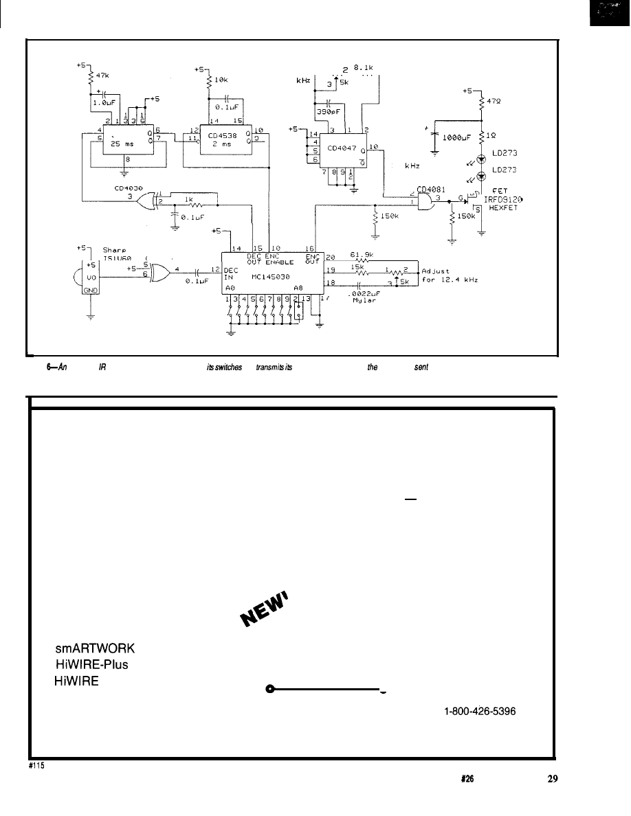
I
,
,
,
A d j u s t
f o r 3 8
CD4538
14 15
C D 4 0 3 0
GEC
3 8
_
A d d r e s s S e t
Figure
intelligent badge has a unique code set on
and
code on/y when it hears
same code
to it
EXPRESS CIRCUITS
MANUFACTURERS OF PROTOTYPE PRINTED CIRCUITS FROM YOUR CAD DESIGNS
TURN AROUND TIMES AVAILABLE FROM 24 HRS
2 WEEKS
Special Support For:
l
TANGO.PCB
l
TANGO SERIES II
l
TANGO PLUS
l
PROTEL AUTOTRAX
l
PROTEL EASYTRAX
l
l
l
II
l
EE DESIGNER I
l
EE DESIGNER III
l
ALL GERBER FORMATS
l
FULL TIME MODEM
l
GERBER PHOTO PLOTTING
l
WE CAN NOW WORK FROM
YOUR EXISTING ARTWORK BY
SCANNING. CALL FOR
DETAILS!
Express
4
Circuits
Quotes:
314 Cothren St., F!O. Box 58
Phone: (919) 667-2100
Wilkesboro, NC 28697
Fax: (919) 667-0487
The Computer Applications Journal
Issue
April/May, 1992
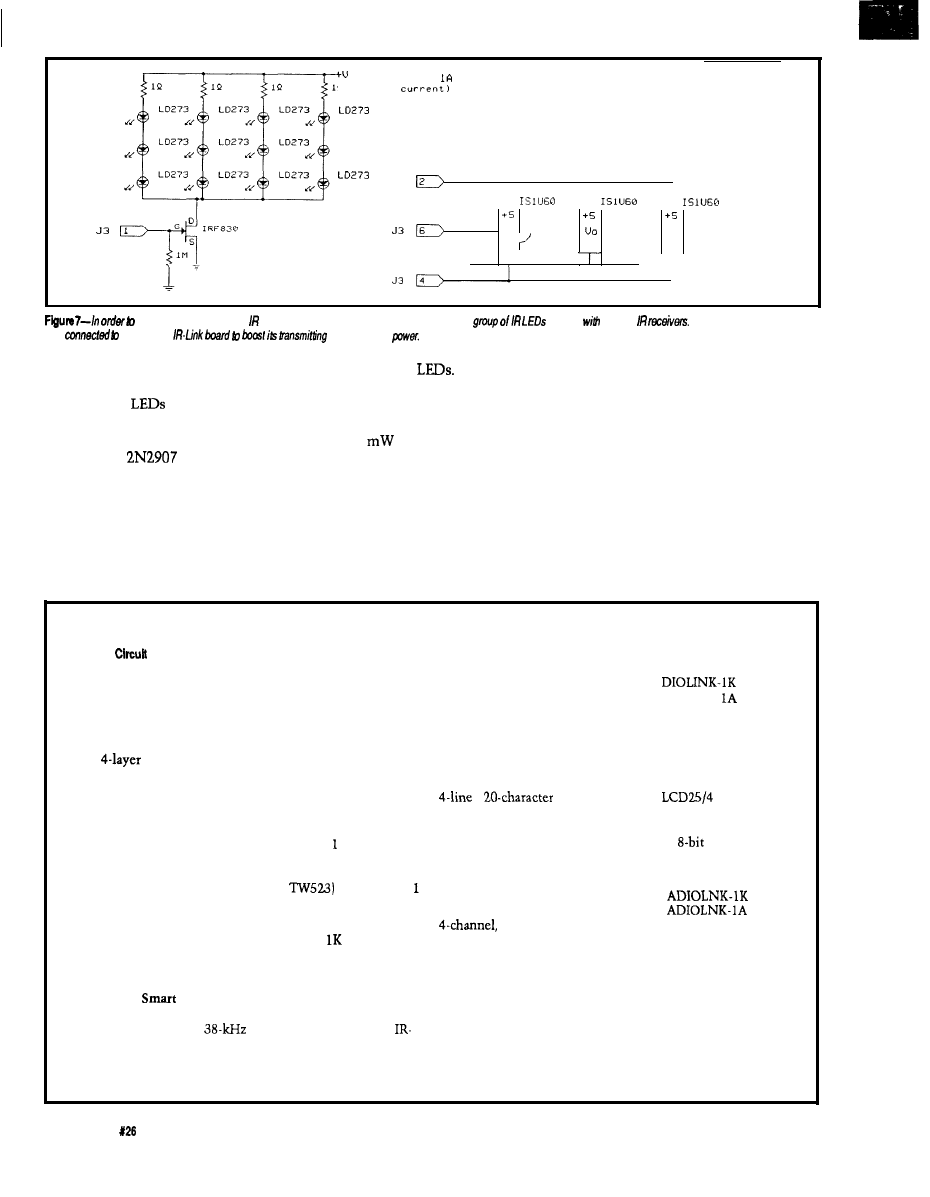
( A d j u s t
for
Q
LED
LD273
J 3
“0
UO
GND
GND
GND
cover a who/e mom with transmissions and receive badge responses, a
is used
several
These extra components
are
the basic
and receiving
different directions to cover a wider
area. However, as a practical matter,
additional IR
should not be
connected in parallel with the LD273
on the IR-Link board because there is
only a single
driver. Instead,
the 6-pin header brings the raw PCM
signal out. This feature should be used
to drive a separate external transistor
or FET.
12 dual-element
Using the
prototype’s own power supply and an
IFR830 FET driver, I was able to
increase the radiant power output from
about 20
(on the single IR-Link
LED) to over 4 watts! A couple
transmitter/receiver “pods” like these
could cover a large office or conference
room quite adequately.
will talk a little more next month
about the remaining links but I’ll be
busy wiring up a storm. If you remem-
ber the picture in the last issue [page
32) of my old HCS, you can compare it
to the new layout here in Photo 4.
Okay, wires are wires.
Showing you this picture will
probably create more questions,
because I took considerable engineer-
ing and poetic license in the physical
assembly of my system. From the very
Photo 3 shows a prototype
IN CONCLUSION
expansion transmitter/receiver that I
Well, this ends my part of the new
built. It contains three IR receivers and
Circuit Cellar HCS II description. Ed
beginning, I have claimed that HCS II
The following is available from:
Cellar Kits
4
Park St.
Vernon, CT 06066
Tel: (203) 8752751
Fax: (203) 872-2204
Hem 1. HCS II Supervisory Controller
HCS II
PC board and all components including HD64180
processor, ADC, real-time clock, battery-backed RAM, IC
sockets, multitasking controller firmware in EPROM, HCS
event compiler on PC diskette, and user’s manual.
Complete kit
order HCSIIK-1
$199.00
Assembled and tested
order HCSIIA-
$269.00
Item
2. PL-Link Smart X-10 Powerline Transmitter/Receiver
PC board and all components (excluding
including 803
processor, RAM, IC sockets, PL-Link firmware in EPROM, and
user’s manual.
Complete kit
order PLINK-
$99.00
Assembled and tested
order PLINK- IA
$159.00
TW523 X-10 power line adapter (not sold separately)
$30.00
Item
3. IR-Link
Infrared Transmitter/Receiver
PC board and all components including 8031 processor, RAM,
IC sockets, infrared LED,
infrared receiver module,
Link firmware in EPROM, and user’s manual.
Complete kit
Assembled and tested
order IRLINK- 1 K
order IRLINK- 1 A
$119.00
$169.00
Item
4. DIO-Link Smart Digital I/O Network Interface
PC board and all components including 8031 processor, RAM,
IC sockets, DIO-Link firmware in EPROM, and user’s manual.
Complete kit
order
$99.00
Assembled and tested
order DIOLINK-
$159.00
Item 5.
LCD-Link Smart 4 x 20 LCD Display Network Interface
PC board and all components including 8031 processor, RAM,
IC sockets, LCD-Link firmware in EPROM, and user’s manual.
Complete kit
order LCDLINK- 1 K
$99.00
x
LCD
order
$59.00
Item
6. ADIO-Link Smart Analog/Digital I/O Network Interface
All components including 8031 processor,
ADC, RAM, 24
bits I/O, IC sockets, ADIO-Link firmware in EPROM, and user’s
manual.
Complete kit
order
$199.00
Assembled and tested
order
$299.00
b-bit DAC upgrade
$35.00
Miscellaneous
12-V modular power supply for link units
Link-Pwr $4.00
5-V 0.9-A modular power supply for HCS II
PS-11
$19.00
All items are shipped FOB Vernon, Connecticut and shipping is
extra. All assembled and tested units come with l-year limited
warranty. A repair service is available to kit builders at an
hourly charge. HCS II, Link designs, and software are available
for commercial license.
3 0
Issue
April/May, 1992
The Computer Applications Journal

was an industrial control system
disguised and downsized as a “con-
sumer-level” home controller (albeit a
consumer with an engineering degree].
Because of my susceptibility to
lightning and general interest in
expanding beyond the basic limits I’ve
described to you, I implemented my
HCS II in its industrial guise so I could
utilize industry-standard isolated I/O.
The large green cards in the center of
the wall contain optoisolators and
relays. They connect by ribbon cable
to a card cage on the right, which
contains the SC and battery-backup
electronics.
I’ll keep you posted on future
developments. I’ve already started
looking at a speech I/O capability for
the HCS II. I’ve selected a fine audio
digitizer that can sound as good as
anything annunciated by the
Enter-
prise’s
computer but I’m having
trouble finding a recognition unit. I
find it hard to believe that no one has
introduced a cost-effective voice
recognition unit beyond the designs I
did using the
chip almost eight
years ago. I suppose if I have to I could
resurrect an old Lis’ner 1000 and nail
an Apple II to the wall. If you manu-
facture a voice recognition board or
know of a workable system, tell me
about it so I can get this project off the
boards.
Steve Ciarcia is an electronics engi-
neer and computer consultant with
experience in process control, digital
design, and product development.
See
the box at the left for the
availability of HCS II modules.
Many of the components used in
this article may be purchased
from:
Pure Unobtainium
89 Burbank Rd.
CT 06084-2416
Voice/fax: (203) 870-9304
404
Very Useful
405 Moderately Useful
406 Not Useful
The
Programming Productivity
3301 Country Club Road, Suite 2214
NY 13760
748-5966
l
FAX: (607) 748-5968
The Computer Applications Journal
Issue
1992
3 1

The Frugal
Networker
Frank Cox
A Crosspoint
Switchboard
for RS-232
id you ever have
one of those prob-
lems that could be
easily solved by buying,
say, $1000 worth of new computer
hardware and software? Well, it hap-
pens to me more often than to most.
But instead of getting out my credit
card, I usually react to these situations
by heating up my soldering iron [not
that I always save money). Sometimes
I come up with something really
useful that more than solves the
problem at hand and that I’ll still use
when I finally do buy a modern
computer. That’s what happened with
the Frugal Networker, a crosspoint
switchboard for the RS-232.
I’m still using a 1980 vintage
80 Model I (and am not ashamed to
admit it!). I also have a serial terminal,
modem, and a few other serial devices,
all of which need to be cross-con-
nected in different ways at different
times. At first I used a bunch of toggle
switches to change connections (and
who hasn’t played the game of swap-
ping cables all over the place?). As I
added new devices, I had to rearrange
my switch setup. There had to be a
better way.
I recently bought a microcontrol-
ler board from New Micros Inc. built
around the
Forth chip,
which is a Motorola 68HC 11 with a
complete Forth language in the chip’s
ROM. The
is an interesting
and powerful chip that has been well
described in several recent Circuit
Cellar INK
articles.
Forth is a minority language.
Some people love it to the point of
fanaticism, or at least that’s what the
people who hate it say. Most don’t
know much about it, and I feel the
latter group is missing out on a useful
tool. In fact, the main reason I still use
my TRS-80 is because it has a good
Forth system. But back to my problem.
The controller board also has an
RS-232 port on it. I started to add some
more toggle switches to my original
network to handle the new serial
device, but the number was getting to
be a bit much. My new board had just
presented me with my next project.
THE GREAT CHIP SWITCH
Chips designed for one purpose
often find homes in other kinds of
applications. I chose the Mite1 Semi-
conductor MT8809 for my project. It’s
an 8 x 8 analog crosspoint switch
designed for use in telephone switch-
ing equipment. I’ll describe using it
with my
but there should be
little trouble adapting it to any system.
The switch contains an array of 64
CMOS transmission gates arranged as
a matrix of eight columns by eight
rows. The columns are called Y
and the rows are called X
(see
Figure 1). A corresponding set of 64
latches acts as a control memory for
this array. These latches in turn are
controlled by a
decoder.
When interfacing it to a controller, all
you need to do is treat it much like a
64-byte by l-bit memory device.
Data on the DATA input is
asynchronously written to the latch
selected by the address on AXO-AY2
whenever
l
CS and *STROBE are held
low, and it’s latched on the rising edge
of *STROBE. A
written to an
address turns on the corresponding
switch and a “0” turns it off. Only the
crosspoint switch being addressed at
the time is changed by a given write,
and any combination of X and Y
can be interconnected by giving the
right sequence of write commands.
Bringing the
l
RESET pin low resets all
latches to “0” and turns off all the
crosspoint switches.
One thing to note is that the
control memory is a WOM (for Write
Only Memory). The control latches
can be written but not read. If software
needs to know the state of the
switches, some method of “remember-
ing” all the writes since the last reset
34
Issue
1992
The Computer Applications Journal
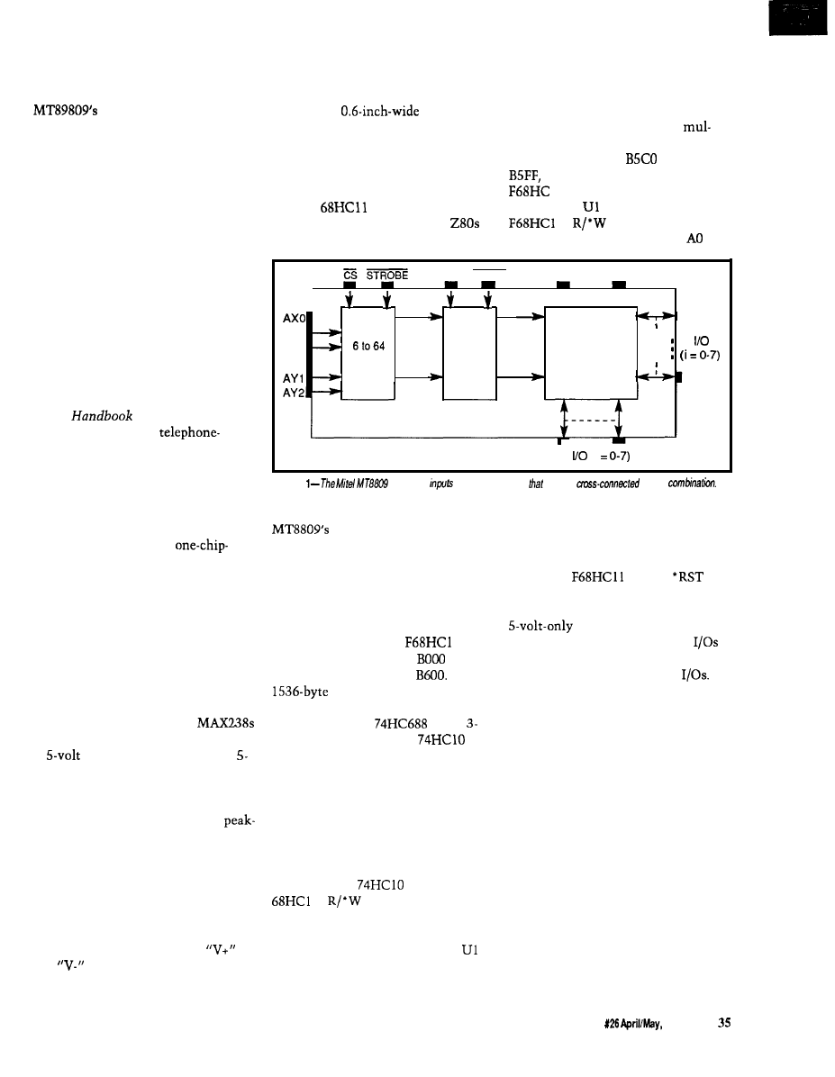
is needed. I’ll talk about some ap-
proaches to this problem later.
Figure 2 lists some of the
specs. Notice the switches
have good frequency response and low
distortion. They should have no
problem handling any speed RS-232
signal. They would also make a good
sound switcher. In fact, other members
of this chip’s family have a third power
supply pm so they can be used with
bipolar analog signals. Designing an
automated sound-mixing board using
this type of chip might be fun.
tion note. Maxim has since come out
with the MAX235, which has these
capacitors inside the package. They
had to use a
package
though, so it wouldn’t save any board
space but it would simplify board
layout and should also increase
reliability. I suggest you try them if
you want to reproduce this design.
The
doesn’t separate
memory and I/O spaces like on
and Intel chips, so I needed to find a
generate
l
CS for U3 and ‘MEMDIS for
the controller. Changing the jumpers
on the B inputs of U2 will move this
block to the upper or lower 64 bytes of
any memory segment that is a
tiple of 256. This block of memory
starts at hex address
and ends at
the last byte before the
1 l’s EEPROM. The remaining
two gates in
combine the
l’s
and E signals to
create a data *STROBE for U3.
Another interesting application
shown in the Mite1 handbook is a
“Test Equipment Switching System,”
which connects a rack of electronic
test equipment to a number of points
in a circuit under test. You could use
these chips to make an automated test
setup. See Mitel’s Analog
Communi-
cations
for more informa-
tion on this and other
oriented chips.
DATA RESET
VDD
vss
-
1
1
I
A X 1
6 x 6
I
AX2
Xi
LATCHES
A Y O -
DECODER
SWITCH
ARRAY
64
64
Yi
(i
THE DESIGN
Figure
has eight
and eight outputs
may be
in any
My first thought was to run the
RS-232 signals right through the
crosspoint switches. This arrangement
would make a neat little
plus-“glue” design and would work
fine as long as the signals didn’t exceed
the power supply voltage to the
transmission gates. Unfortunately, the
Mite1 devices only handle a maximum
of 12 volts peak-to-peak and an RS-232
can be as much as 30 volts. Also, I
wanted to plug my circuit into the
expansion jack of a microcontroller
board with only 5 volts available.
good place in the memory map for the
64 bytes. The New Micros
board has a
l
MEMDIS pin on the
expansion jack that makes this search
easier. Pulling ‘MEMDIS low disables
RAM, allowing a section of memory to
be “notched out” by an external
device. A neat feature. The New
Micros chip moves the
l’s 64
configuration registers to
and its
5 12 bytes of EEPROM to
The
“island” between them
seemed like a good place to put my
switcher. I used a
plus a
input NAND gate from a
to
build my address decoder, which gives
a lot of flexibility to move the address
around later if I want to.
through A5 go to U3 and select one of
64 addresses, and DATA comes from
the HC 1 l’s DO line.
The *RESET pin of the MT8809 is
tied to the
board’s
line, so the whole system is reset at
once. U4 and U5 are the Maxim quad
receivers and drivers. The
receivers are connected to the X
of the crosspoint switches and the line
drivers are connected to the Y
THE PHYSICAL DESIGN
I decided to use a pair of
so I could run the transmission gates
at
logic level. These are quad
volt-only RS-232 line drivers and
receivers from the wizards at Maxim.
This choice gave me eight receivers
that can withstand a full 30 volts
to-peak and eight line drivers that can
put out a “legal” RS-232 signal using
on-chip “charge pump” DC-DC
converters.
With a decoder giving a ‘CS and
l
MEMDIS signal each time my device
is addressed, all I needed was the
proper *STROBE whenever a write
took place. Using the remaining two
gates from the
to combine the
l’s
and E signals took
care of this requirement.
The New Micros
board uses a
vertical stacking-type connector for
the expansion jack, so it was natural
for me to piggyback my board on top of
theirs. I used modular phone-type
jacks for my RS-232 I/O and found that
eight of these jacks side by side are
exactly the same width as the control-
ler board! These connectors are taller
than the distance between the boards,
so I just hung them over the edge.
A MAX238 needs four external
capacitors for its power supply, so I
used a total of eight in my prototype,
but two chips can share larger
and
caps as shown in the sche-
matic, according to a Maxim applica-
Figure 3 shows the schematic of
the circuit. U2 and one gate from
form the address decoder that responds
to a 64-byte block of memory to
Now when I say “RS-232,” what I
really am describing is the two serial
lines and signal ground. I’ve been
blissfully living my life without ever
using the other signals that are part of
a real RS-232 connection, and I’ve
The Computer Applications Journal
Issue
1992
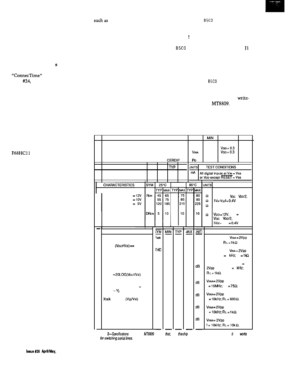
avoided most of the confusion associ-
ated with this messy standard. How-
ever, I realize not everyone can avoid
doing so. I used 4-pin jacks for this
project and just made up the way they
are wired because there is no standard
for wiring RJ- 11 jacks in RS-232
applications. In retrospect, I should
have used 6-pin RJ- 11 just in case I
need the other pins some day. See
in
Circuit Cellar INK,
issue
for a good discussion on the
use of RJ-11 jacks in RS-232 connec-
tions.
I built everything up on 0. 1”-grid
prototyping board with a ground plane
on one side, gold-plated through-holes,
and pads on the other side. It probably
would work without the ground plane,
but I feel safer using it. I wired the
circuit point-to-point.
THE SOFTWARE
As I mentioned previously, the
has a complete language in
8K of on-chip ROM. This New Micros
version of Forth is called Max-Forth.
Like most Forths, it’s an integrated
compiler, interpreter, assembler, and
operating system. I won’t go into its
many features here, but I would
encourage anyone who hasn’t checked
out Forth to do so. Forth is an excel-
lent microcontroller language because
of its power, small size, and ease of
development.
I’ll just present a simple applica-
tion program to show you how the
Frugal Networker works. Although I
suspect most readers don’t know
Forth, I think these examples will be
understandable to most programmers.
If you try this circuit with another
language, I hope the algorithms I
provide will help you.
To begin, I have eight jacks, each
with an incoming and an outgoing
signal line. Normally, I would want to
connect two devices together by
connecting the transmitter of one to
the receiver of the other and vice
versa. But doing so would mean
turning on two switches, and I’ll want
to connect the attached devices
together in different ways to do
different jobs. I don’t want to turn on
and off different configurations of
switches. Being able to type something
"PC modem CONNECT" and
"terminal PC DISCONNECT" would
be nice, as would being able to group
commands. For example,
"WELL"
could mean “connect the terminal to
the modem and also let the computer
listen, then dial the WELL and ignore
all traffic on this line until I tell you to
turn everything off again.” Doing this
sort of thing is easy in Forth, and
having an on-line language system
means you can build commands like
this example as you need them.
I first need to build a few “primi-
tives,” though I’m not sure this
description is the best one for a Forth
word. To turn a switch on and off, I
need to write a “1” or a “0” to the
respective corresponding address. So in
Forth, I could type
HEX
C! <ENTER>
H EX will turn on hexadecimal mode
and C (pronounced “C Store”) will
write an 8-bit value of 1 to hex address
and connect the input of jack
to its output making a loop-back for
anything plugged in there.
Now that the hex arithmetic is set
I can type
0
C!
to turn it off again.
I’ve already mentioned the
only nature of the
One way
around the problem of being unable to
read the state of the switches is to just
turn them all off before each new
setup. I’ll define a Forth word to do
PARAMETER
S Y M B O L
MAX
UNITS
1
Supply Voltage
V
DD
-0.3
15.0
V
vss
-0.3
V
2
Analog Input Voltage
-0.3
V
6
Package Power Dissipation
PLASTIC DIP Po
0.6
W
1 .o
W
CHARACTERISTICS
S Y M M I N
M A X
1
Quiescent Supply Current
1 2 0 4 0 0
1
On-state
V
DD
Resistance
V
DD
V
DD
2
Difference in on-state
resistance between
two switches
70°C
75
65
215
10
TEST CONDITIONS
VSS = OV,
=
Vss 0,
=
Vyjl
3
CHARACTERISTICS
Frequency Response
Channel “ON”
20LOG
-3dB
Total Harmonic Distortion
TEST CONDITIONS
45
MHZ
Switch is “ON”;
sinewave;
0.01
%
Switch is “ON”;
sine wave f 1
R
L
Feedthrough
Channel “OFF
Feed.
‘DT
- 9 5
All Switches ‘OFF”; W
NA
sine wave f 1
Crosstalk between any two
channels for switches Xi Yi
and Xj
= 20LOG
(tall
- 4 5
- 9 0
sine wave
f
R
L
sine wave
f
- 6 5
sine wave
f
- 6 0
sine wave
Figure
for he
show
while
was designed for voice switching, a/so
well
36
1992
The Computer
Applications Journal
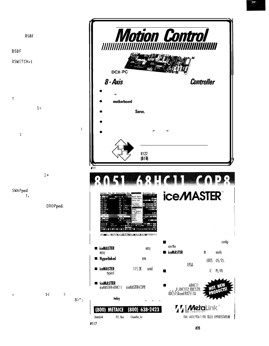
this action, but first I’ll define a
constant named XSWITCH. Thus,
CONSTANT XSWITCH
Recall from the above discussion that
is 1 byte before the first address
of the Frugal Networker. That way
is the first address of my
switcher. Actually, it would be
XSWITCH 1 + because Forth, like a
Hewlett-Packard calculator, uses
stack-oriented “postfix” arithmetic.
Now to define the word
ALL
. 0 FF:
ALL.OFF XSWITCH
40 0 DO
DUP 0 SWAP C!
LOOP DROP
For non-Forthers, I’ll explain that the
and delineate a Forth definition.
Typing in the above code or loading it
from mass storage will compile it into
memory as a word that will execute
whenever called. Invoking the word
A L L
. 0
F F
will zero all 64 crosspoint
switches and turn them “all off.”
The 40 and 0 are the loop indices
in hex. The word increments the
address X SW I
TCH,
which is on the
stack. Then, 0 is put on the stack and
into proper position for the
word C
After performing these steps
64 times, the leftover address, now
XSWITCH + 64, is
I know
this process is a little messy, and you
Forth programmers are thinking I’m
nuts for not using the much faster and
shorter F I
L L
or
ERASE
commands.
Well, I would have used them but the
MT8809, or at least the one I have,
doesn’t seem to want to take the data
that fast.
Now I’ll define some words such
as 1 2 ON, which will let me connect
input 1 to output 2, or something
similar like 1 2
OFF.
But first I
should do a reality check; I can only
allow the numbers 1 through 8. I’ll
make this limit with two words.
RANGE? DUP SWAP 8 OR
A B O R T ’ < n e e d 2 n u m b e r s 1 t o
RANGE? makes a copy of the top of the
stack and if it’s not 1 through 8,
Position and/or Velocity
Programmable Motion
State-of-the-art Digital Muhifunction Controller can be configured in minutes
using off -the-shelf” components
DCX
contains intelligence/memory/firmware and 8 sockets for
“plug-in” Modules
1 to 8 “plug-in” DC
Stepper or Special Purpose Control Modules can
be mixed/matched on same DCX board
Install in any PC/XT/AT compatible, or use “stand-alone” with RS232
and/or IEEE-488 interface Modules
High level interface libraries in C” and BASIC,” with examples and source
code, included
Precision Micro Control
C
O
R
P
O
R
A
T
I
O
N
Engineer Road, San
Diego, CA 92111
5654500
FAX (619) 565-1511
6
Rental And 1 O-Day Trials Available
delivers productivity:
to learn,
to use and fast!
On-line help guides
through the
emulotion process.
is FAST! The
baud
link
keeps
downlood times to under 3 seconds using a
stondord COMM port!
Your
Window
To Emulation
Productivity
is Versatile:
iceMASTER- 51,
and
support most
family derivatives.
Call
for
FREE DEMO DISK!
Call today to ask about FREE 8051
Macro
Assembler!
Flexible user interface: you
ran completely
windows
for size, content, location and color.
is convenient!
connects
to your
PC, requires no disassembly, nor does it take up any
expansion slots. It works on ony PC
or
Micro Channel or
Even laptops!
Supports source level debug
and
and
source level trace. 4K trace buffer with advanced
searching
and
filtering capabilities.
New
Products!
A D E
Corporotion
1329
85244-1329 Phone: (602) 9260797
The Computer Applications Journal
Issue
April/May, 1992
37
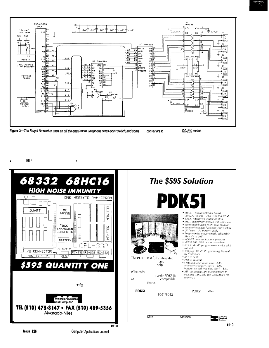
level
make a smart
ABORT” will send the message to the
CHECK will RANGE? the top two
I need to take these two numbers
terminal, empty the stack, and return
numbers on the sack. If either is out of
and make one number that I can add to
to the prompt averting the danger.
range or if there is only one of them,
the base address of our crosspoint
then it’s ABORT” time. If all is well,
switcher to turn on the desired switch.
CHECK
RANGE? OVER RANGE?
then they are left as they were found.
The matrix of numbers I need to add to
Our FOUR layered CPU and I/O boards are
designed for tough factory floor environments.
Custom design and board
available.
Please call for specifics.
33476
Blvd.. Suite 6
Union City, CA 94587
to
8051 System Development
hardware, firmware,
software
system designed to
you develop
your products quickly and cost
All you need to
IBM-PC/XT/AT or
We supply
PLUS
includes everything in the
plus
3 of out
popular BXC51
BASIC compiler-$800.
Call Now! 603-469-3232 or FAX 603-469-3530
q
Binary Technology, Inc.
Street . PO Box 67 .
NH 03770
38
April/May, 1992
The
XSWITCH, or
is, in decimal,
1 2 3
6 7 8
9 10 11 12 13 14 15 16: 2
17 18 19 20 21 22 23 24: 3 o
u
t
27 42 43 44 45 46 47 48: 6
28 50 51 52 53 54 55 56: 7
57 58 59 60 61 62 63 64: 8
and I can use
: CALC
8ROT
15
Looks unfathomable? Nothing to
it really. Remember, I’ll have two
numbers on the stack, 1 through 8,
“in” and “out.”
CALC
multiplies the
out value by 8, leaving 8,
or 64. These numbers make
up the last column on the table. I put
an 8 on top of the stack and ROT the in
value up from third to the top of the
stack and subtract it from 8. Then I
subtract this result from the result of
multiplying the out value by 8 and I’m
done. This math works the same way
in hex, but the table looks stranger.
Let me illustrate what I’ve just
explained.
3 5
8 * 5 is 40
8 ROT
gives 5
40 5 = 35
From the table you can see that 3
in, 5 out is in fact 35. Bingo. Now
you’re ready for
:ON CHECK CALC XSWITCH 1
SWAP C! :
:OFF CHECK CALC XSWITCH + 0
SWAP C!
:
The SWAP is needed to put the address
and value in the proper order for
finicky C
I am now able to type in things
like 1 2 ON and make new words by
SETUP1 ALL.OFF 1 8 ON 8 1 ON
: SETUP2 ALL.OFF 1 5 ON 5 1 ON
1 7 0 N 7 1 0 N :
I’m sure you get the idea. I’ll also
make two other words:
CONNECT
ON SWAP ON
: DISCONNECT
OFF SWAP OFF
1 2
thesameas 1 2 ON
2 1 ON, andsimilarlyfor
N
ECT.
At this point, I can add a few
other features to this little application.
For example, I’ll declare the jacks that
my various devices are plugged into as
constants. Thus,
5 CONSTANT modem 6 CONSTANT PC
7 CONSTANT terminal
8 CONSTANT 100s
That
last
one,
by
the way, is
the
New
Micros “100 Squared” board. The
controller’s RS-232 port can be plugged
into one of the jacks so it can switch
itself around the network. Even
though these are called constants,
their values can be changed later with
the help of the word or TICK.
The
is a versatile
microcontroller
board. It is ideal for quickly developing products,
prototypes or test fixtures.
l
microcontroller
1 compatible)
l
BASIC-52 or MONITOR-52 available
l
Program in C, BASIC or assembly language
l
8 to 92K RAM, EPROM or EEPROM
l
Breadboard area and expansion bus
l
RS-232 port and 12 digital I/O lines
l
$100 for 11 MHz, $145 for 20 MHz
3 9
CP-1128
Combination Programmer
$1295.00
230
and MAX
isp
National Semiconductor’s
-5D -7D
devices ond
devices.
and recommended
AMD.
Lattice.
conductor, Signeticsond others.
Utilizes only manufacturer
proved programming algo-
rithms.
Supports
E P R O M s a n d b i p o l a r
i n c l u d i n g t h e
microwire
devices.
/Supports
conductor
and
DSP320, Micro-
chip PIC
microcontrollers.
Lifetime
FREE
updates available
BBS
and US Mail.
Call for
DEMO
disk
and literature pack.
in the USA
EP-1140
E/EPROM
Programmer
$895.00
The EP-1
s u p p o r t s
Qualified
and
mended by Intel, Signetics,
E P R O M ,
Notional Semiconductor,
1 6 b i t E P R O M s , F L A S H o t h e r s
E P R O M s ,
Lifetime
FREE software up
EPROMs.
dotes available via BBS and
A l l I n t e l , A M D , o n d
US Mail.
Risk-free thirtyday
supported directly.
bock
Made in the USA
With lifetime
FREE software updates, you can’t
go wrong and BP Microsystems offers o thirty-day
money-back guarantee to ensure product satis-
faction. Remember, BP Microsystems is...
The Engineer’s
B
P
-
MICROSYSTEMS
10681 Haddington
l
Houston, TX 77043.3239
(713) 461.9430
l
FAX (713) 461.7413
1991 BP
Inc.
I need one more word before I can
define the word WELL, which I men-
tioned previously. STAND . BY essen-
tially says “do nothing until I tell
BEGIN
I F K E Y 1 8 =
E L S E 0
THEN
UNTIL
This word loops or stands by until it
sees an
18 hex or
CONTROL-X.
So if I want a command that dials
the WELL and sets me up for an on-
line session, I could use
w e l l
100s modem ON
415 332 7398” CR CR
100s modem
OFF
terminal modem CONNECT
pc modem
CONNECT
( f o r
terminal modem DISCONNECT
pc modem
DISCONNECT
terminal 100s CONNECT
You probably recognize that ATDT as a
command to the modem to dial a
number.
Notice these few lines of code that
I’ve shown have already built up a
useful program. You can embellish it
to best fit your application. One
improvement would be a STAND. BY
word that does more than just waste
time looping. Max-Forth allows multi-
tasking as one fancy way of improving
it. Another alternative is to use some
other interrupt-driven scheme. I’ll
leave that as an exercise for you.
Finally, I’d like to cover some
other solutions to the WOM problem I
mentioned earlier. There will be times
when you won’t want to disturb a
connection by using A L L . 0 F F. What
you can do is declare a
variable
to store an image of the crosspoint
matrix. Then you modify 0 N, 0 F F, and
ALL . 0 FF to write to both places. You
could write a neat little routine to
display the results in, say, an 8 x 8
matrix. Another way would be to work
out a compression and decompression
scheme and store an image in only 8
bytes because there is really only 64
bits of data involved. This method is
good if you want to store a lot of
complicated “prerecorded” setups.
I hope you find the Frugal
Networker interesting and that it leads
you to other ideas using the MT8809
family. Also, I hope I’ve convinced you
to use Forth as a small systems
language. Just so I don’t leave you with
the impression that I’m a monomaniac
concerning this subject, let me explain
that I intend to use Pascal and C in
upcoming projects, but as long as I
have the Frugal Networker, I won’t
forget my Forth.
Frank Cox is back as a full-time
student studying science and engi-
neering with an emphasis on electron-
ics after spending many years in
industry.
Software for this article is avail-
able from the Circuit Cellar BBS
and on Software On Disk for this
issue. Please see the end of
in this issue for
downloading and ordering infor-
mation.
Many of the components used in
this article may be purchased
from:
Pure Unobtainium
89 Burbank Rd.
CT 06084-2416
Voice/fax: (203) 870-9304
Mite1 Semiconductor
4320 Stevens Creek Blvd., Suite 225
San Jose, CA 95129
(408) 249-2111
Fax: (408) 249-1635
407
Very Useful
408 Moderately Useful
409 Not Useful
40
Issue
1992
The Computer Applications Journal
Ken Davidson
Programming the
Home Control System II
ave you taken a
good look at what
is on the market
these days for home
automation systems? At the low end is
the X-10
controller. You plug
this box into a PC, set on and off times
for a bunch of X- modules, and
disconnect the PC. While inexpensive,
it is nothing more than an
program timer.
Next is the Enerlogic ES-1400. It
uses a language similar to what I’m
about to describe, but, again, it can
only talk to X-IO modules. Its advan-
tage over the
is its capability to
receive from the power line and base
decisions on what it hears, but it has
no direct inputs or outputs. How do
you connect a motion detector,
level sensor, or temperature sensor to
it? There are X-10 units that send
commands onto the power line based
on motion and light level, but given
the reliability of X- 10 transmissions,
do you really want to trust them?
At the high end of the scale are
the units that start in the $3000 range
and can only be obtained through
“authorized dealers” who must do all
the installation and programming.
What good are these devices to
experimenters who know what they
want to do, and just need some
specialized hardware to do it!
There
are a few low-cost systems
available that allow the experimenter
to add hardware piecemeal and do the
programming, but they are based on
the premise that you don’t mind
leaving your 200-W IBM PC running
all the time to do the controlling. I
wouldn’t want to see that electric bill.
And what happens when your kids
want to play Tetris?
HCS II REVISITED
In
the last issue of
Circuit Cellar
INK,
Steve introduced the new Circuit
Cellar Home Control System II and I
discussed the brains of the operation:
the supervisory controller. The HCS II
is based on a number of separate
building blocks that may be connected
using a network made up of a single
twisted-pair wire and is designed for
people who know what they want to
do and how to do it, but need some
low-cost hardware and software to use
as tools.
The Supervisory Controller
(SC)
is
responsible for determining how the
system operates and when things
happen. It has 24 bits of
I/O
(optionally up to 48 bits of buffered I/O
in addition) and eight channels of 8-bit
analog-to-digital conversion. The
Link module handles all X- 10 power
line communication, including both
transmitting and receiving. The
Link [which Steve and Ed discuss in
this issue) allows you to issue com-
mands with a hand-held infrared
controller. The LCD-Link contains an
LCD display that responds to a subset
of standard ANSI terminal control
sequences and also has four bits of I/O.
The DIO-Link adds eight bits of TTL
I/O, and its cousin, the
includes 24 bits of I/O, eight channels
of
analog-to-digital conversion,
and four channels of 8-bit
analog conversion. Up to 32 of these
modules may be connected to a single
network, although cost will probably
limit system size to fewer than that.
A complete HCS II system can be
as simple as a lone SC, or as compli-
cated as you want to make it.
COMMUNICATE THIS
While the HCS II is made up of
several autonomous building blocks,
42
1992
The Computer Applications Journal
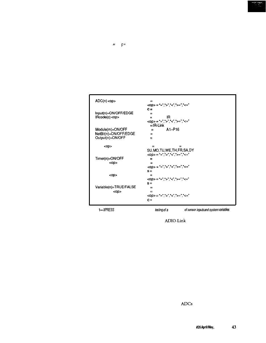
you need some way of interacting with
the system as a whole in order to
program it. In any properly configured
home control system, you should be
able to set it and forget it, so we use an
IBM PC compatible for doing the
“setting,” then disconnect it when
finished to do the “forgetting.”
The program used to communi-
cate with the SC is called HOST. When
run, HOST displays a number of
windows containing such information
as current time and date, current state
of X-10 modules (you decide which
housecodes), current state of local
inputs and outputs, and what network
modules are in use. HOST allows you to
set a new time and date (it actually
reads it from the host PC, so be sure
you’ve set it correctly before running
HOST) and allows you to load a new
program into the SC. I’ll cover where
that program comes from next.
THE LANGUAGE OF
HOMEOWNERS
The
original HCS that Steve
presented about seven years ago had a
simple menu-driven interface and
control scheme. It gave the user
several programming options including
turning an X-10 module or direct
output on and off at specific times, in
response to an input, or after a specific
time period. While that scheme is easy
to use and allows a good degree of
control, it falls well short of meeting
the needs of a more sophisticated
control system that may be applied to
both industrial and home environ-
ments.
Suppose I have an area with two
lights, two motion sensors, and a door
sensor. I want the lights to come on if
either of the motion sensors is tripped,
then go off 15 minutes after no motion
is detected. I also want the lights to
come on if the door is opened and to
stay on as long as the door is open,
regardless of motion. When you have a
system like the old HCS, where you
could only key actions on a single
input, such a scenario is impossible to
realize without additional circuitry to
combine the sensors external to the
HCS. Remember this situation for
later and you’ll see how easy it is to do
with the new system.
The HCS II programming language
is called XPRESS (expandable Pro-
grammable Real-time Event Supervi-
sory System) and is based on what I
call an “event equation.” The equation
consists of an I section, followed
by a "THEN" section. If the I F section
is true, the TH EN section is executed. If
not, the action is skipped. It’s as
simple as that. Much of the power
comes from being able to combine any
number of conditions in the I F
inputs. Network inputs (tested with
portion, and have any number of
the N ETB I T keyword) are those found
actions initiated in the TH EN portion.
on the LCD-Link, DIO-Link, and
a
high state and an edge. A falling edge
is tested by checking for both a low
state and an edge. Inputs are broken
into two categories: local inputs and
network inputs. Local inputs [tested
with the I N P UT keyword) are those
connected directly to the SC and are
the fastest to test. Any device that
needs quick action (like a motion
detector at the top of a flight of stairs)
should be connected to one of the local
c
n
n analog-to-digital channel
constant g-255
n input number O-239
c received cede O-255
Reset
Time
hh:mm:dd
Timer(n)
s
Timer(n)
s
Variable(n)
c
n
module number O-7
m module
n network I/O bit number O-239
n output number C-239
True after reset
hh hour O-23; mm min O-59; dd = day
(daily)
n timer number O-63
n timer number 031
O-65535 seconds
n timer number 32-63
O-65535 minutes
n variable number O-15
n variable number O-15
constant g-255
Figure
condition keywords a/low the
wide range
CONDITIONAL CONTROL
Figure 1 shows a summary of valid
I F statement conditions. I’ve done a
lot of work on the system since the
last article was written, and have
expanded on what was presented there.
I’ll quickly explain how each of the
conditions works. [I know a laundry
list of mostly self-explanatory com-
mands can be dry, so I’ll try to be
brief.) Note as you go through the list
that many systems on the market
allow you to base actions on time or
on inputs, but rarely allow you to
combine the two as we do here.
Inputs may be tested for a high
state [on), a low state (off), or an edge
(either rising or falling). To test for a
rising edge, you simply check for both
modules. Since these
modules must be polled over the
network, system response to a net-
work input is somewhat slower than
to a direct input.
Similarly, the current state of any
output may be tested for either on or
off. As with inputs, there are local
outputs (tested with OUTPUT) and
network outputs (tested, as with
network inputs, with N ETB I T). The
same issue of response time applies to
outputs as to inputs.
Analog inputs may also be tested
using the ADC keyword. A single
keyword is used for both local and
network
because there are far
fewer potential analog inputs than
either digital inputs or outputs.
The Computer Applications Journal
Issue
1992
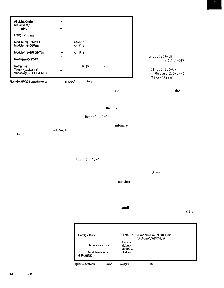
DAC(
Output(n)=ON/OFF
h housecode A-P
h housecode A-P
n digital-to-analog channel
c = constant O-255
n = LCD-Link number O-7
string = any ASCII text string
m = module
m = module
n dim level l-31
m module
n bright level l-31
n = network output bit O-239
n = output number O-239
r = refresh interval
minutes (0 off)
n timer number O-63
n = variable number O-15
give you
plenty
over
your
environment
The
current
state of any X-10
module may be tested for either on or
off using the
MODULE
keyword. There
is no easy way to keep track of a lamp
module’s dimmed intensity, so we
don’t even try. A dimmed lamp simply
shows up as being on.
The current time of day may be
tested in a number of ways using the
TIM E keyword. The typical
and operators may be used to
compare the time with a constant
made up of hour, minute, and day of
week. There isn’t any way to make
comparisons with month or day of
month, but we found little use for
such comparisons and left them out.
There are many situations where
elapsed time must be measured. A
common example is turning a light on
for a certain number of minutes when
motion is detected, then turning it off.
Sixty-four timers are defined for the
HCS II: 32 that time in seconds and 32
that time in minutes. Each timer may
be tested for whether it is on or off,
and may be checked for whether it is
less than, equal to, or greater than a
constant value using the TIMER
keyword. Before you think I’m crazy
for providing 64 timers, keep in mind
who the primary user of this new
system is [Steve) and what his control
requirements must be.
For those cases where a counter
must be maintained or simple true and
false states must be stored, there are
16
S-bit variables available.
When multiple IR-Links are
connected to the system, knowing
which IR-Link received a particular
code or command from the remote
is sometimes necessary. Using the
I RCODE keyword, you can test
On the other side of
coin is the
action list following the THEN state-
ment. Figure 2 lists all the valid
whether a particular code was received
actions. Any number of actions may be
by either a particular
or a
listed, either on separate lines or
range of IR-Links. For example, writing
separated by semicolons. The list is
“I
F I
13
tests whether
always terminated with an END
code 13
was
received by IR-Link
statement. As before, I’ll quickly
number 0. You can
use
the
describe each action, trying not to be
tion to produce different responses
too arid.
based on which room the transmission
Any X-
10
module may be turned
came from. When the IR-Links are
on or off, dimmed, or brightened.
used as part of a people locator system,
Similarly, an “All Lights On” or “All
knowing which IR-Link received the
Units Off” command may be sent out
code tells you where a certain person
to any given housecode.
is located. A statement like
“I F
Outputs may be turned on or off.
I
13
can be used to see if
The same distinction is made between
the code was received by any IR-Link.
local and network outputs as for the
Steve’s article in this issue covers the
I F
tests. Analog outputs may also be
IR-Link in more detail.
set to any
value.
Finally, setting up default states
Timers may be turned on or off.
when the system is reset and
When a timer is turned on, it is cleared
ing from a known condition is often
to zero and starts counting. If you
useful. The RESET keyword tests true
want to clear a timer that is already
just once on the first pass through the
on, simply turning it on again will
event equations after a reset, then tests
clear the count. Turning a timer off
false from then on.
forces all tests on that timer to return
Now that you have all the
a false response.
tions under your belt, it’s time to
Variables may be set to any
combine them into useful tests. Any
value or to true or false. Like many
number of conditions may be com-
bined in a single I F statement using
NOT, AND, OR, and parentheses. A NOT
preceding any of the above conditions
complements the result. AN Ds and 0 Rs
do pretty much as you’d expect. Some
examples of valid conditions might
include
IF
A N D
Modul
o r
IF
A N D
O R
JUST DO IT
!
Begin
n
Define
Display
Start of comment
Start of program
= alphanumeric string up to 32 characters
any valid program statement
X-10 module housecodes
Start and end of global IF
keywords
you
to
your system on he and make programs more readable.
Issue
April/May, 1992
The Computer Applications Journal
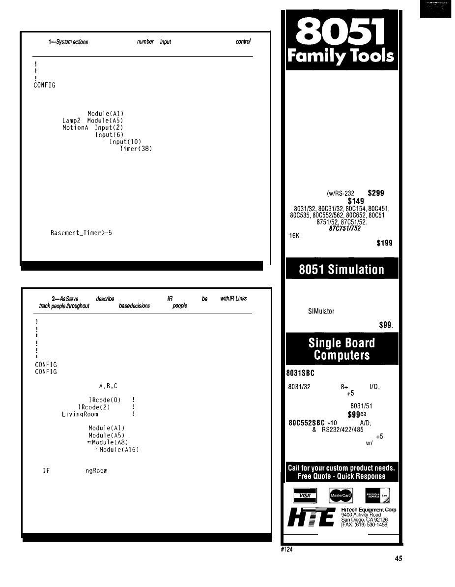
Listing
may be based on any
of
conditions, making complex
scenarios realizable.
Example HCS II Program
PL-Link = 1
DISPLAY Modules = A
DEFINE Lamp1 =
D E F I N E
=
D E F I N E
=
DEFINE Motion6 =
DEFINE Door-Sensor =
DEFINE Basement-Timer =
BEGIN
IF MotionA=EDGE OR MotionB=EDGE THEN
Lamp1 = ON: Lamp2 = ON
Basement-Timer = ON
END
IF Door_Sensor=ON THEN
Lamp1 = ON: Lamp2 = ON
END
IF
AND Door_Sensor=OFF THEN
Lamp1 = OFF: Lamp2 = OFF
Basement-Timer = OFF
END
Listing
and Ed
elsewhere in his issue, badges may used
to
a house and
on where
are located.
Demonstrate use of
I R b a d g e s f o r t r a c k i n g
Be n i c e t o S t e v e . b u t r a z z E d i f h e w a l k s
in t h e r o o m w i t h o u t S t e v e
PL-Link = 1
IR-Link = 3
DISPLAY Modules =
DEFINE Steve =
Badge number 0
DEFINE Ed =
Badge number 2
DEFINE
= 1
IR-Link number 1
DEFINE Lamp1 =
DEFINE Lamp2 =
DEFINE Stereo
D E F I N E A i r - H o r n
BEGIN
Steve=Li vi
THEN
Lamp1 = ON; Lamp2 = ON
Stereo = ON
END
IF Ed=LivingRoom AND NOT Steve=LivingRoom THEN
Air-Horn = ON
Lamp1 = OFF; Lamp2 = OFF
END
In Circuit Emulators
The DrylCE Plus is a modular emulator
designed so you can get maximum
flexibility from your emulator purchase.
The base unit contains all the hardware
necessary to support pods containing
many of the most popular members of the
8051 family of embedded control
microprocessors. Buy one base unit, and
select one or all of the pods you need to
do the job at a much reduced cost. You
get the same great functionality found in
our popular DrylCE 8031 emulator plus
real-time Execute-to-Breakpoint,
Line-by-Line Assembler, and much more.
And the price is (almost) unbelievable!
(Yes, it works with the Mac, too!)
Base Unit
IF) --
Available Pods:
each
FA,
Call about
support
Trace Buffer option: Avail. 2nd Qtr ‘92
Standard 8031 DrylCE -- Still only
Enhanced 8031 DrylCE --
$269
The 8051SIM software package speeds
the development of 8051 family
programs by allowing execution and
debug without a target system. The
8051
is a screen oriented,
menu command driven program
doubling as a great learning tool.
-A fast and inexpensive way to
implement an embedded controller.
processor, parallel
up to
2 RS232 serial ports, volt operation.
The development board option allows
simple debugging of
family
programs.
bit 8 ch.
2 PWM,
1 RS232 2
serial ports,
sockets for 64k ROM, 64k RAM, volt
operation; optional RT Clock battery,
2k EEPROM. Development board version
available. Call for pricing!
(619) 566-1892
The Computer Applications Journal
Issue X26 April/May, 1992
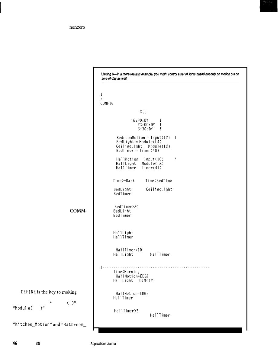
other programming languages, false is
simply zero while true is any
value. Variables may also be incre-
mented or decremented for use as
counters. When a variable reaches
zero, further decrementing has no
effect. Likewise, when one reaches
255, incrementing does nothing. No
other math besides incrementing and
decrementing is supported.
Text messages may be sent to any
LCD-Link in the system. A very useful
subset of the ANSI cursor control
commands has been implemented on
the LCD-Link, and the SC allows you
to send any of these commands to the
display module.
Finally, the PL-Link’s refresh
period may be set. If you’ll recall Ed’s
article in the last issue, the PL-Link
may be set to send out on or off
commands periodically to all modules
it’s referenced since its last reset. That
way, any module accidentally triggered
by garbage on the power line will be
set back to its proper state. Setting the
period equal to zero turns refresh off.
BELLS AND WHISTLES
Besides the basic language build-
ing blocks discussed above, there are
additional commands and features that
are used for configuration or to make
the programmer’s job easier. Figure 3
lists these extra keywords.
The SC must know what
Link modules are connected to the
network so it doesn’t waste its time
polling modules that aren’t there. The
CON FI G keyword is used to define how
many of each of the COMM-Link
modules are out there. If the program
contains no CON FI G statements at all,
the SC simply doesn’t access the
network.
HOST displays the current state of
any X- 10 module, local input, or local
output you ask. The D I SPLAY keyword
is used to define just what housecodes
you want displayed.
programs more readable. Instead of
using keywords like I n p u t 2 and
L3 when writing a
program, DE F I N E lets you give such
keywords descriptive labels like
Light."
After all the definitions, a single
BEG I N is used to denote the start of
the program.
One last keyword used in pro-
gramming is the global I F, or G I F.
“Global” probably isn’t quite the right
word, but it seems to fit the best. GI F
allows a single level of nesting of I F
statements. The G I F keyword is
followed by any valid combination of
conditions. If it evaluates true, then
any number of I F/THEN combinations
following it up to the GE N D are
executed. If it evaluates false, the
whole block is skipped. G I F allows
you to selectively execute or skip
! Practical
example of different system behavior
depending on the time of day
PL-Link = 1
DISPLAY Modules =
DEFINE Dark =
Sunset
DEFINE Bedtime =
Time for bed
DEFINE Morning =
Starting to get light out
DEFINE
Bedroom motion detector
DEFINE
DEFINE
=
DEFINE
DEFINE
=
Hallway motion detector
DEFINE
=
DEFINE
=
BEGIN
GIF
AND
THEN
IF BedroomMotion=EDGE THEN
= ON;
= ON
= ON
END
IF
THEN
= OFF: Ceilinglight = OFF
= OFF
END
IF HallMotion=EDGE THEN
= ON
= ON
END
IF
THEN
= OFF:
= OFF
END
GEND
GIF
THEN
IF
AND HallLight=OFF THEN
=
END
IF
THEN
= ON
END
IF
THEN
Halllight = OFF:
= OFF
END
GEND
Issue April/May, 1992
The Computer
whole portions of a program depending
on some condition. Check out some of
the example programs I present later if
you’re still not clear about G I F.
Finally, comments are preceded by
an exclamation mark All text
following the
up to the end of the
line is skipped.
COMPILE TIME
The
program actually run by the
SC is made up of binary representa-
tions of the keywords I described
above. I presented the basic format of
that binary in the last issue. In order to
translate from the English-like
program developed by the user to the
binary used by the SC, a compiler is
necessary. Simply named C OM P I L E,
the compiler runs on an IBM PC
compatible and takes as input straight
ASCII text entered with any text
editor, does a syntax check, and
generates a file called EVENTS. BIN
containing the raw binary code used by
the SC.
When the user running HOST
presses the “L” key, HOST looks for
EVENTS. BIN, loads it into memory,
and sends it to the SC. The SC imme-
diately starts running the new program
and the HOST screen reconfigures itself
assuming the transfer went all right..
PROGRAMMING
CONSIDERATIONS
A key idea to keep in mind is that
a program is made up of a series of
event equations. The SC continually
runs through the list over and over
again. Any action that takes place near
the top of the program could affect the
evaluation of equations later in the
list, so a certain precedence can be
achieved by where in the list a particu-
lar equation falls.
Input levels and edges stay static
throughout a pass through the list,
changing only after a pass is complete.
An input edge is always cleared at the
end of a pass, but may be tested
multiple times in a single pass.
One concept I’m sure is going to
bite some people is once an equation
evaluates true and its companion
action has been carried out, that action
won’t be executed again until the
equation evaluates false at least once,
then true again. For example, suppose I
when using those commands to avoid
have the statement:
repeat transmissions.
IF
THEN
= ON
END
LEARNING BY EXAMPLE
If were to send out an on com-
mand to module J2 every time the
condition Input 3
evaluated
true, I’d have a very busy power line
until input 3 went off. Executing the
on command just once, then skipping
it until input 3 goes off, then on again
is one way to get around the problem.
I find the easiest way to learn
something new is by practical applica-
tion of the concepts. I’ve listed all the
keywords and rules involved in writing
a program, but a few simple examples
should help clear up some of the haze
in the air.
Another way I get around the
above problem is to be a little smart
about X- 10 commands. Transmitting
an on command to a module if the
module is already on is kind of silly.
Therefore, I check the status table
first, and if the module is on, I don’t
send another command. This check
doesn’t work for bright or dim com-
mands, because the light will likely be
already on when you want to dim or
brighten it to a new level, so you have
to make your program a bit smarter
Let me go back to the scenario I
cited earlier. I have two motion
detectors, two lights, and a door
sensor. Listing
1 shows one way a
program can be written to solve the
control problem. The first equation
looks for an edge on either motion
detector and turns on the lights if it
finds one. It also starts a timer. The
next equation checks the door sensor
and, if the lights haven’t already been
turned on by motion, it turns them on.
The last statement checks the timer to
find out if five minutes have elapsed. If
so, and the door is closed, the lights
are turned off and the timer is stopped.
If the door is open, the lights stay on
The Computer Applications Journal
Issue
April/May, 1992
4 7
until it is closed. Also note that if
motion is detected again before the
timer times out, the timer is restarted
from zero. The result is the lights stay
on for five minutes from the last
detected motion, and not the first.
Since we’re dealing with the
Link elsewhere in the issue, how about
an example of performing one set of
tasks based on the presence of a
particular person, and another if that
person is absent? Listing 2 shows such
code. When Steve walks into the living
room wearing his badge, the system
will be nice and turn on the lights and
stereo. If Ed happens to walk into the
same room, but Steve isn’t there, we’ll
razz him with an air horn and turn the
lights off. If Steve is with him, though,
we’ll be nice again because we don’t
want to subject Steve to all that noise.
For something more practical,
suppose you have a motion detector in
the bedroom and you want the lights
to come on after dark. You really don’t
want the lights coming on during the
night every time you turn over in bed,
and you also don’t want them to come
on when it’s light out. Similarly, you
have a motion detector in the hall just
outside the bedroom and you want the
hall light to come on when it’s dark.
However, if you happen to take a trip
to the bathroom during the night,
you’d like the hall light to come on
and dim down to a tolerable level.
Listing 3 shows how such a setup
might be done. It also points out a
number of programming
that will likely bite novice HCS II
programmers. The first global if is only
executed between the time it gets dark
out and when you go to bed. The
statements are very similar to those in
the other examples, with lights going
on in response to motion, and off in
response to a timeout.
In the second global if, take a look
at the condition. The HCS II time of
day is based on a midnight-to-mid-
night cycle, so the condition responds
as if it were written
IF
AND
THEN
When counting from 0 to
it’s not
necessary to test if the value is greater
Photo 1-A
screen displayed by
10
16
inputs and
SC,
and
time and date. The size of the windows and amount
of
displayed
change
depending the equipment
you
have in your system.
than or equal to it always will be.
The same applies here. Obviously, the
hall lights won’t come on between
bedtime and midnight, but how often
do you get up within the first hour
after you’ve gone to bed? If it’s a
problem for you, just add a bit more
intelligence to the program to fill the
gap.
Next, notice the extra condition in
the first I F statement and the extra I F
statement following it. Remember I
said that if an X-10 module is already
on, I don’t send another on command.
That is why the previous statements
can be written without checks to see if
the light is
it’s done automatically.
If motion is detected after the light is
turned on and before the timer times
out, the timer will be cleared but the
on command is skipped. When you’re
dealing with dim (and bright) com-
mands, though, you have to be
smarter. You may want to intention-
ally dim a light that is already on, so I
can’t block the dim command like I
can the on command. You have to add
an extra condition to check for
whether the light is off, and send the
dim command only if it is. That way
the command is only executed once
and you don’t end up with a light
dimmed all the way to black. The
second I F statement is necessary to
retrigger the timer should more
motion be detected before the timer
times out.
When the conditions in neither
G I F are met, which is true any time
it’s light out, then nothing happens in
response to any of the motion detec-
tors, which is just what we want.
CONTROLLING THE FUTURE
That about does it for version 1.0
of the HCS II. As we get more feedback
from those of you living with the
system, we‘ll be refining it to more
closely meet your needs. Let us know
what you think.
q
Ken Davidson is the managing editor
and a member of the Computer
Applications
engineering
staff. He holds
a
B.S.
in computer
engineering and an M.S. in computer
science from Rensselaer Polytechnic
Institute.
Please see page 3 1 for more
information about the availability
of HCS II components.
410
Very Useful
411
Moderately Useful
412
Not Useful
The Computer Applications Journal
issue
April/May, 1992
4 9
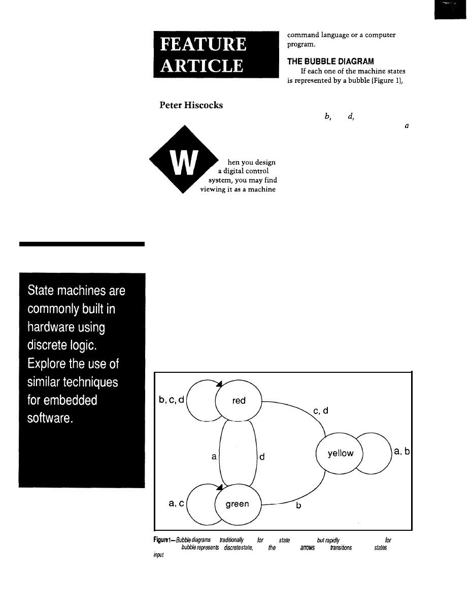
State
Machines
in Software
A Design
Technique for
Single-Chip
Microprocessors
with a number of states useful. The
classic example is a traffic light: it has
a red state, a green state, and a yellow
state. It may also have other states: left
turn, advanced green, flashing, pedes-
trians-only crossing, all stop, and so
forth. The state machine is particu-
larly effective at detecting, preventing,
and signaling errors in input from a
human operator. For that reason, you
should always seriously consider a
state machine as the basis for a user
interface design.
State machines are also very
effective at decoding messages. This
then the transition from one state to
another is represented by an arrow.
Associated with the arrow is input
condition a, c, or which allows
the transition to occur. For example,
might represent the transition condi-
tion stop timer time-out and cause a
transition from the red state to the
green state.
Generally, most assume that the
default condition is for the state
machine to stay in a particular state.
However, showing a transition, with a
condition, looping back into the
current state is sometimes useful. This
representation indicates that the
condition causes the machine to stay
in that particular state.
The outputs from the state
machine are not shown on Figure
1,
but of course they must occur for the
machine to be useful. Outputs are
produced from a state machine during
either a particular state or the transi-
tion between states. For example,
consider the transition from red to
green. I may indicate that the red state
attribute makes them useful in
actuates the red light: an output
communication systems like network
conditional on a particular state.
protocols, and in parsing the text of a
Alternatively, I could indicate next to
are
used small
diagrams,
become unwieldy /age
ones. Each
a
while lines and
show
between
based on
conditions.
52
Issue X26 April/May,
1992
The Computer Applications Journal
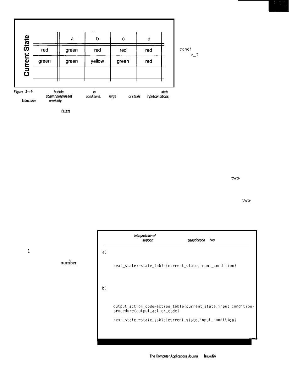
Input Condition
yellow
yellow
yellow
red
red
p/ace
of
the
diagram, a state &b/e sometimes used. The mws represent the current
of
the machine while the
the input
For a
number
and
he
state
becomes
the green-red transition
on red
makes it very easy to debug and to
light, turn off green light.
modify.
THE STATE TABLE
Bubble diagrams like Figure 1 are
useful for small state diagrams, but
rapidly get unwieldy for large ones.
The number of possible transitions
grows as an exponential function of
the number of states, so a state
diagram quickly outgrows small sheets
of paper.
A better approach is to use a
state
table,
an array that usually has the
rows representing the
current stnte
of
the machine and the columns repre-
senting the
input conditions. Thus,
each entry in the state table represents
one possible combination of a current
state and an input condition. This
organization is one of the advantages
of the state table: it forces the consid-
eration of all possible states and all
possible inputs. The state machine
represented by the bubble diagram in
Figure is shown as a state table in
Figure 2.
Again, with a large
of
states and inputs the state table
eventually becomes unwieldy, and you
must eventually resort to a different
approach. One possibility is to break
the single large table into several
smaller tables.
The state table technique is an
example of a
table driven
program: its
behavior is defined by a data structure
rather than by a block of procedural
code. Once the procedure that
inter-
prets
the table is fully debugged, the
system will operate according to the
contents of the state table. This aspect
Each entry of the table has two
parts:
l
the
next state
of the machine
. the
output action
to occur with
this transition
If there is no transition for a given
state, then the next state is simply the
current state. If a particular input does
not occur during a particular state,
then you can choose to have the state
machine ignore the input or generate
an error message. The error message
can be quite informative because a
particular input has occurred in a
particular state (e.g., “Can’t push that
button while the light is red”].
The interpretation of the state
machine, ignoring outputs for a
moment, can be reduced to a five-line
program similar to what I’ve shown in
Listing la. This code says the next
state of the machine is determined by
the current-state and the
i n p u t _
ti on. The
program reads the
s t a t
a b 1 e matrix to determine the
next state, and then sets current_
s t a t e
equal to that value.
Now, how do I handle outputs? In
BASIC and assembly language, I use
two arrays, each two-dimensional,
each addressed by current state and
input condition: a
next stote array
and
an
output action array.
The output
action array contains numbers that are
codes for various output actions. The
processor looks up the action code
corresponding to the current state and
input condition, and then uses it to
determine what action routine it
should call.
The pseudocode I provided in
Listing la now becomes that in Listing
lb. Of course, in assembly language
you don’t usually have instructions to
access entries of an array, and a great
deal of singing and dancing is required
to simulate the effect of a
dimensional storage array with
sequential lists.
If I use C to design the state table
data structure, each entry has a
part structure consisting of a next state
and an output action. The program
enters the table with current state and
input condition, and reads the next
Listing
1-a)
the state machine, ignoring outputs, can be reduced to a five-line
program. b) Adding output
increases the size of he
by
lines.
do
read input-condition
current_state:=next_state
loop
do
read input-condition
current_state:=next_state
loop
April/May,
1992
53
state and output action out of the
structure entry in the array.
A STATE MACHINE IN
PSEUDOCODE
The
code in Listing 2 is the
stoplight state machine, coded in a
sort of high-level pseudolanguage. This
code seems like an awful lot of
program to define the behavior of the
stoplight, but most of it is in defini-
tions. This listing will be eliminated
in the machine code for a compiled
language or assembly language. In
return, you have a very error-resistant
program, which may be easily modi-
fied with the addition of states.
Changing the behavior of the state
machine is a matter of changing the
entries in the two tables.
A STATE MACHINE IN ASSEMBLY
LANGUAGE
Now
I will discuss how a state
machine approach can be used in a
6805 microprocessor. Implementing a
state machine in assembly language on
this type of processor presents some
Listing 2-When the
machine coded in a
high-/eve/
he bulk of
consists
define the size of the next-state array
dimension
dimension
define the array indices
Next States:
yellow:=2
Input Conditions
b:=l
Define the 'next state' array
(continued)
VOICE MODULES
VM-1410A $75
EPROM)
Issue April/May, 1992
The Computer Applications Journal
* Plays natural-sounding voice/sound
* Holds up to 10 messages
* Max. length: 12 seconds 32Kbps
* Built-in
power amplifier
* Single 6 12 VDC operation
* Voice digitization: VP-880 ($495)
* Demostration EPROM available
* Other models available
* For security alarms, P.O.S. promo-
* Includes a CVSD
chip
1870) and a filter module (SF-700)
* Sampling rate is adjustable from 9.6
to 128 Kbps
* Universal
interface
* Advanced CMOS technology
* Single 3 6 VDC operation
* Other models available
* For digital recorders, digital answer-
tions, amusement parks, elevators..
ing machines, PC voice boards..
VOICE
CHIPS
PC VOICE BOARDS
VCS-1870 voice chip set
V-Link/l voice board $145
* Single-line, IBM PC compatible
* Connects to telephone line or PBX
* Records and plays messages
* Automatic answering and dialing
* Touch tone/dial tone detection
* Requires additional programming
* Software developer’s kit ($150) for
Microsoft C, Turbo C and Clipper
* Multi-line models available
* For voice mail, voice response..
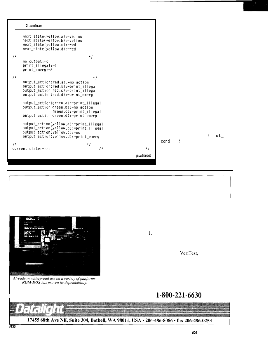
Listing
Define the 'output-action' codes
Define the 'output-action' array
output-action
action
Now. finally, the program:
start in state 0
challenges. The
Motorola 68000
has a
number of instructions that support
this kind of program, but single-chip
micros like the
6805
do not, and you
are forced to use some “ingenious
hacks.”
IMPLEMENTING THE NEXT
STATE
To recap, I wish to store next state
addresses in a two-dimensional array
and access the next state address by
two indices.
Let me discuss how the next state
section of the program would appear in
the 6805 [refer to Listing 3a). To begin,
I will consider how the machinery
works to determine the next state. [In
fact, I actually do the output action
before changing the state, but the
latter is easier to understand, so I’ll do
it first.)
I assume the location n p
i t on
is properly set by external
events. To retrieve the next state from
the next state table, I need some kind
of indexed
LDA
instruction. In 6805
assembler, it is of the form
DOS Where You Want It
-Runs
on Disk, ROM, FLASH
Develop
your programs on a standard PC and run them in
ROM with ROM-DOS, the flexible, affordable operating
system that was designed for embedded applications. Compat-
ible with MS-DOS 3.3 ROM-DOS boots and runs from
ROM, disk, or FLASH memory. Features include: small size
(low as 36K); runs executable files from ROM; FLASH disk
support; remote disk and multimedia support; and a powerful
utility suite. Confirmed compatible by
an independ-
ent evaluator, ROM-DOS is already in widespread use on
multiple system types. Developers Kit-which contains all the
tools and utilities needed to configure ROM-DOS to your
system, and includes license for 20 copies-costs only $495.
ROM-DOS royalty fees depend on quantity purchased, and
range from $3 to $25 per copy.
Free Demo Disk! Call Today Toll-Free
The Computer Applications Journal
issue
April/May, 1992
5.5
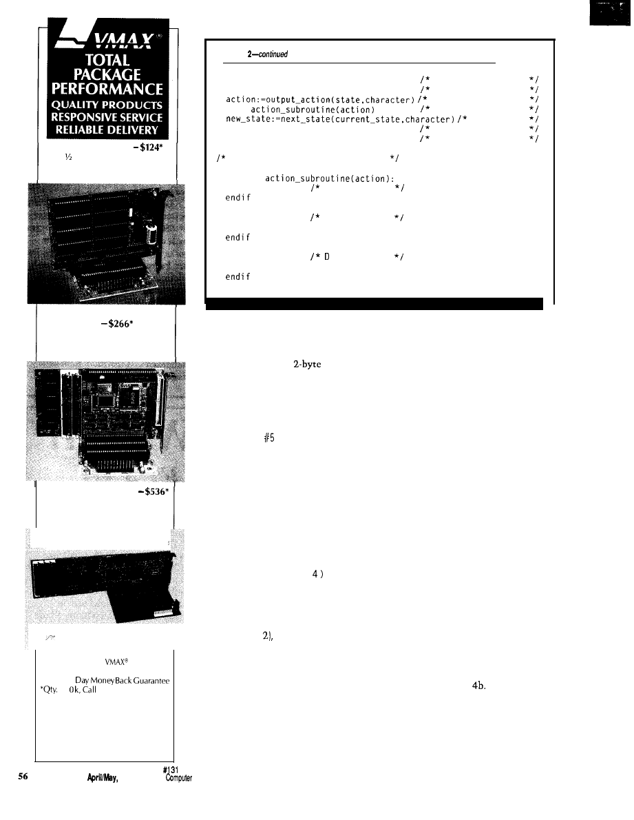
SOLID STATE DISK
Card 2 Disk Emulator
EPROM, Flash and/or SRAM
1 Meg Total, Bootable
TURBO XT WITH FLASH
DISK
2 Serial, 1 Parallel Port
Up to 2 Flash Drives, 1 Meg Total
Software Included, 2 Meg DRAM
20 MHz AT CPU CARD
4 Meg DRAM, 0 to 60 C
2 Serial, 1 Parallel Port
CMOS, Low Power, Surface Mount
All Tempustech
products
are PC Bus Compatible. Made
in
U.S.A.,30
10,
for Quantity
Pricing
TEMPUSTECH, INC.
TEL: (800) 634-0701
FAX: (813) 643-4981
Fax for
fast response!
295 Airport Road
Naples, FL 33942
Listing
do
the main loop
get character
accept input char
get action code
call
do output action
next state
current_state:=new_state
move to new state
loop
end of main loop
These are the action routines
procedure
if action:=0
no output
if action:=1
illegal input
print "Illegal input'
if action:=2
key input
print "Emergency Red"
return
LDA WORD, X
Usually, resolving such an issue isn’t
this simple. Note the X register can
where WORD is some
quantity
and X is the content of the X index
register. The effective address is the
sum of
WORD
and the contents of the X
index register. For example,
LDX
LDA 200. X
would have the effect of loading the
accumulator with the contents of
location 205.
So recognizing that I have four
input conditions in my table, the offset
into the table of a next state will be
given by
(current-state x
+
i n p u t - c o n d i t i o n
For example, if the current state is
GREEN (i.e., 1) and the input condi-
tion is C (i.e., then the table offset
of the desired next state entry is 6.
Using assembly language, I would
retrieve the next state as shown in
Listing 3b.
All well and good. But notice, I
avoid having to use a multiply by
selecting a number of input conditions
that is a power of two. The “multiply”
is accomplished by using left shifts.
Issue 126
1992
The
Applications
Journal
only accommodate 8 bits, which limits
my total table offset to 255 bits
maximum.
THE OUTPUT ACTION
MACHINERY
First, I define the various actions
by numerical codes and construct the
output action table shown in Listing
4a. This time, I have to retrieve an
action code from the table and act on
it. The offsets into the two tables will
be identical because the next state and
action code tables are the same size
and structure. Once the offset into the
next state table is calculated, I can also
use it to retrieve an action code.
Now, I wish to jump to an action
routine based on the value of the
action code retrieved from the table.
The 6805 indexed JSR instruction,
together with a jump table, will
accomplish the task.
I assume that the action code
routines exist somewhere in memory.
(The preface AR_ indicates an action
routine.) See Listing
Why, you may
ask, bother with the no action routine
when all it contains is a
NOP?
Because
if you ever want to add something to
the system, you simply replace the
NOP
in the action routine with the
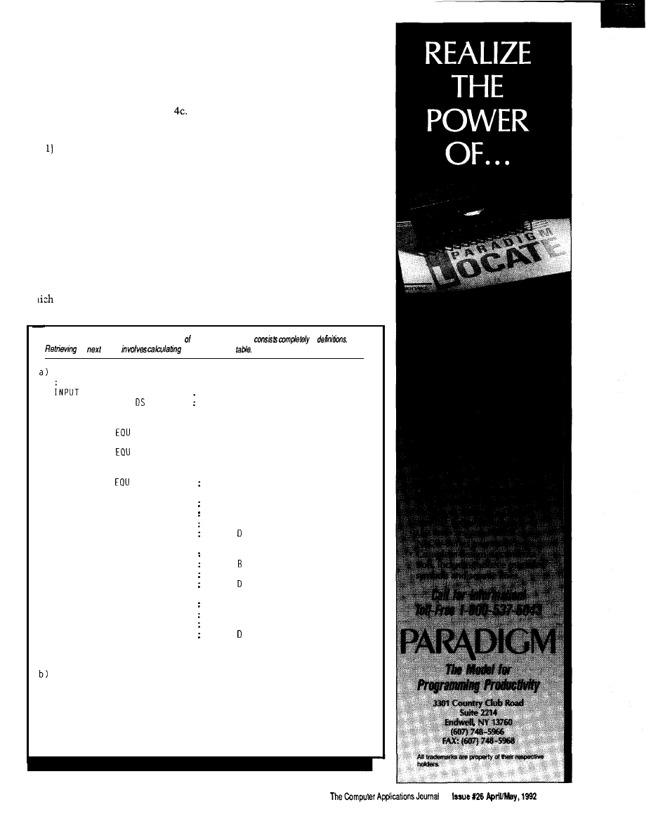
desired code. The routine makes the
system much easier to maintain.
Now, I need to make a jump table
out of the addresses of these routines,
putting them in the order of their
action codes, as shown in Listing
You access the action routine with
a four-step process:
Determine the index into the
action code table the same way as I
determined the index into the next
state table.
jump table is a 3-byte J MP instruction.
4) Set up the offset as an index and
do an indexed J SR through the table,
2) Retrieve the action code from
the table using this index.
3) Multiply the action code by 3 to
get the offset into the jump table
because each entry of the action code
wh
will send the processor to the
appropriate action routine. The action
routine terminates with an RTS
instruction, sending the processor back
to the main interpreter loop. The code
for this setup is shown in Listing 4d.
The JSR JMP_TABLE,X instruc-
tion sends the program to the correct
entry in the jump table, the jump table
entry sends the program to the action
routine, then the action routine does
what’s required and does an RTS back
to the main routine.
THE PUSH AND RTS HACK
instruction. In that case, I’ve included
Some microprocessors do not have
an indexed J SR instruction. The 6502
is one of these, but it does have a PUSH
a useful trick below:
1)
Set up a table containing the
addresses of the action routines
Listing 3-a)
The 6805 implementation the next state section
of
b)
he
state
an offset into the
CONDITION DS 1
CURRENT-STATE
1
:
Next
state
definitions
R
ED
0
GREEN
EQU 1
YELLOW
2
: Next state table:
NEXT-STATE
*
STATE-RED DB
GREEN
DB
RED
DB
RED
DB
RED
STATE-GREEN DB
GREEN
DB
YELLOW
DB
GREEN
DB
RED
STATE_YEL DB
YELLOW
DB
YELLOW
DB
RED
DB
RED
LDA CURRENT-STATE
ASL
ASL
ADC INPUT_CONDITION
TAX
LDA NEXT_STATE,X
STA CURRENT-STATE
Input variable
Current. state variable (in RAM)
Name the start of the table
Input A
Input. B
Input C
Input.
Input A
Input
Input C
Input
Input A
Input B
Input C
Input.
Get the current state
Multiply by number of input
conditions. in this case 4
Add in the input condition
Move table offset. to X register
Next state is now in A
Jump to the next state
5 7
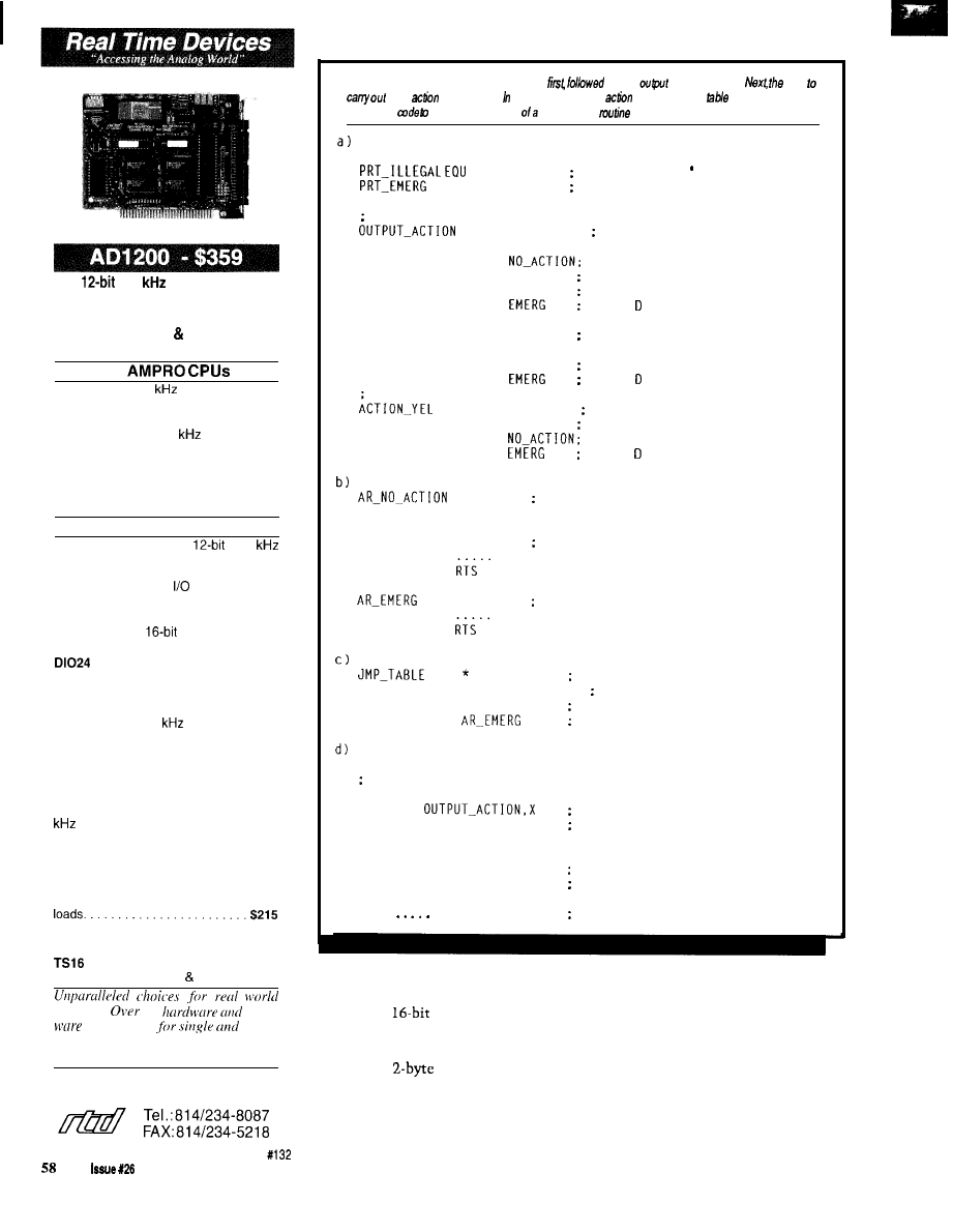
Exciting New Products!
l
125
A/D Conversion
l
16 Analog input Channels
l
3 Timers and 16 DIO Lines
l
Supports DMA Pacer Clock
l
AT Bus Version Available!
for
DM200 12-bit 40
8 channel analog
input board; 8254 timer and 16 digital
I/O lines $295
DM406 12-bit 100
16 channel
analog I/O board; 2 D/A outputs; 8254
timer; 16 digital I/O lines; Supports DMA
and pacer clock. $449
DM806 High current digital I/O board;
8254 timer; opto-22 compatible $195
PC/XT/AT Boards
AD2700 16 channel
150
analog input board; Supports DMA,
pacer clock and programmable gain;
8254 timer; 16 digital
lines; 16-bit AT
bus operation. $525
TC48 Dual Am951 3 Timer/Counters; 24
digital I/O lines;
AT bus operation
w i t h e x p a n d e d i n t e r r u p t s . $ 3 9 8
High current digital I/O board; 24
buffered DIO lines; 8254 timer; Com-
patible with opto-22 equipment $195
AD3110 Super fast 16 channel A/D
board! 12-bit 200
A/D rate; Burst
mode
operation; On board FIFO
memory; Programmable gain; Timers;
DIO lines; Supports DMA and pacer
clock; Optional D/A outputs $665
AD3710 Low cost version of AD3110
with on board FIFO memory and 200
b u r s t m o d e o p e r a t i o n $ 5 2 5
DA810 8 channel 12-bit D/A; Voltage or
current loop output; 8254 timer; 24 digi-
tal I/O lines $589
MR16 110 VAC mechanical relay expan-
sion board; Computer control of 16 AC
0P16 Optoisolated 16 channel digital
input expansion board. $225
16 channel thermocouple expan-
sion board; Supports J K types. $298
c o n t r o l .
50
soft-
p r o d u c t s
O E M
users.
FREE 80 PAGE CATALOG!
Real Time
Devices, Inc.
State College,
PA
USA
Listing
4-a) The action codes are defined
by the
action table. b)
wde
each
is defined. c) order to get to each
routine, a jump
is defined. d) Last
comes the
retrieve he address
given action
and jump to it.
NO-ACTION
EOU 0
: n o a c t i o n
1
p r i n t
‘ i l l e g a l
EOU 2
p r i n t
‘emergency’
O u t p u t a c t i o n t a b l e :
E O U *
N a m e s t a r t o f t a b l e
ACTION-RED DB
DB
DB
DB
ACTION-GREEN DB
DB
DB
DB
D
B
DB
DB
DB
NOP
RTS
AR-ILLEGAL
. . . . .
. . . . .
EOU
I n p u t A
ILLEGAL
Input B
ILLEGAL
Input C
Input
ILLEGAL
I n p u t A
NO-ACTION; Input B
ILLEGAL
Input C
Input
I L L E G A L Input A
ILLEGAL
Input B
I n p u t C
Input
‘ n o a c t i o n ’ a c t i o n r o u t i n e
p r i n t
‘ i l l e g a l
p r i n t
‘emergency’
a c t i o n r o u t i n e s j u m p t a b l e
JMP AR_NO_ACTION
action code 0
JMP AR-ILLEGAL
a c t i o n c o d e 1
JMP
a c t i o n c o d e 2
W e a s s u m e t h e o f f s e t o f t h e a c t i o n c o d e i s i n t h e X r e g i s t e r
LDA
r e t r i e v e a c t i o n c o d e f r o m t a b l e
STA TEMP
m u l t i p l y i t b y 3
ASL
( f i r s t m u l t i p l y b y 2
ADC TEMP
a n d t h e n a d d i t i n a g a i n )
t o g e t t h e j u m p t a b l e o f f s e t
TAX
set up
for indexed jsr
JSR JMP_TABLE.X
: jump to the vector in the table
a c t i o n r o u t i n e R T S r e t u r n s h e r e
somewhere in ROM. Each table entry,
assuming a
address bus, will
consist of a low and high address byte.
2) Index into this table and
retrieve the
address of the
action routine using the action code.
3) Push the 2 bytes of the action
routine onto the stack in the same
order that a subroutine call would do
it.
4) Execute an RTS instruction.
The effect of an RTS
is to
pop the
address off the stack and jump to it. In
effect, this hack gives me the capabil-
ity of a computed jump.
April/May, 1992
The Computer Applications Journal
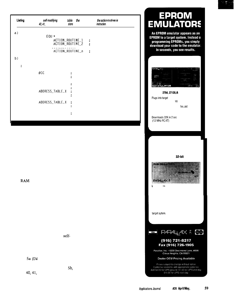
5-a)
To utilize
wde, a
of addresses of
necessary.
b) RAM locations
and 42 are used to
the synthetic jump
ADDRESS-TABLE
DW
Address of routine 1
DW
Address of routine 2
..etc......
DW
Address of routine n
Assume X contains the action opcode
LDA
Store the op code for JMP
STA $40
at location 40 in RAM
LDX ACTION_CODE
Get the action opcode
ASLX
Double it
LDA
Get high byte of action routine
STA $41
and store it in RAM
INCX
LDA
Get low byte of
action routine
STA 642
and store it in
RAM
JSR $0040
Do
a JSR
through constructed
JMP
:
instruction. to action routine
SELF-MODIFYING CODE
The final method, an alternative
for the 6805, is similar to the PUSH and
RTS hack. Rather than do an indexed
J SR though a jump table, I have the
program construct a J M P instruction
with an address that points at the
desired action routine. The address
associated with the J M P will change,
so the instruction must be constructed
in the
area of the processor.
The addresses of the action
routines are set up in a table much like
the jump table. The processor uses the
action code to index into the action
routine address table, retrieves the
action routine address (2 bytes), and
then stores the action code address
[prefixed by the opcode for J MP) in
three locations in RAM. The processor
then does a J SR to the first of these
three RAM locations.
The 6805 code that uses the
modifying code method for vectoring
to an action routine is shown below.
Here, I assume the addresses of the
action routines are stored in a table as
in Listing
is the assembler
operative for define word).
In the code fragment in Listing
locations
and 42 are used to
store the synthetic jump instruction.
COMPARING VECTORING
METHODS
I have examined three different
methods of vectoring to action
routines based on an action opcode.
Which is best for your particular
application?
The advantages of the jump table
method are that it is entirely con-
tained in ROM [does not require RAM
registers) and can be done without
PUSH and POP instructions. The
disadvantage is it requires a jump table
containing 3 bytes for every action
routine.
The PUSH and RTS method has the
advantage of using a shorter action
code routines table and 2 bytes per
action routine. However, the action
code table does require that the
assembler be able to extract the low
and high bytes of an address for each
entry.
The self-modifying code method
has the advantageous PUSH and RTS
method, but it does not require that
the microprocessor have a PUSH
instruction. However, it does require 3
precious bytes of RAM and induces a
slightly queasy feeling in those who
adhere to the tenets of structured
programming.
27256 EPROM EMULATOR
Emulates
27256 EPROMs.
EPROM socket and
connects
to PC parallel port telephone cable.
Loads Intel. Motorola,
binary files.
Reset
outputs
restarttargetafterdownloading.
$ 1 9 9
27010 EPROM EMULATOR
Up to 4 units can be daisy-chained to
emulate consecutive EPROMs and to
support 16 and
systems.
Emulates 2764, 27128, 27256, 27512, and
27010 EPROMs.
Plugs into target EPROM socket and connects
to PC parallel portviatelephone cable.
Reset
outputs
restart
$ 3 4 9
The Computer
Issue
1992
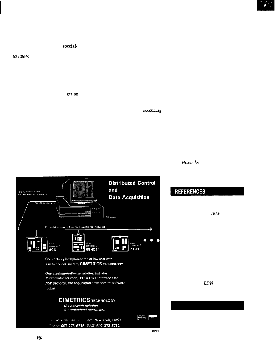
A CASE HISTORY
Comparing the state machine
technique with a more conventional
approach to building a microprocessor
program is interesting. The case
history I describe here is a
purpose terminal, which uses the
microprocessor, containing a
16 x 1 LCD character display and a 4 x
3 keypad. Pressing keys causes the
processor to select or edit displays, or
to send messages out a serial RS-232
port.
I originally wrote the code for this
project using the brute force
input-compare-and-branch approach.
However, the result contained a great
number of conditional and uncondi-
tional branch statements. Alarmed at
what looked like a massive debugging
effort, I then rewrote the code using
the state machine approach.
Both programs required about the
same amount of RAM: 24 versus 25
bytes. The compare-and-branch
method required 1540 bytes of EPROM
for the entire program: tests, branches,
and subroutines. The state machine,
which contained eight states and nine
possible inputs, was 121 bytes smaller.
This decrement is not a great saving,
but it does indicate that a problem of
this magnitude will be smaller if the
state machine approach is used. The
benefit from the state machine method
would probably increase with larger
programs.
The big advantage of the state
machine approach shows in the
number of decision and jump state-
ments. Unlike the load and store
instructions, branches tend to be a
source of error. For example, condi-
tional branch instructions are usually
associated with loops, making it easy
to introduce errors such as
a
loop too many or too few times, or
inadvertently branching past code.
Thus, the number of branch state-
ments can be taken as a very rough
indicator of
code complexity.
In this example, the control logic
of the compare-and-branch method
contained 140 branch statements, but
the control logic of the state machine
method contained 18 branch state-
ments: three in the state machine logic
and sixteen in the action routines
(there are an additional 21 JMP
instructions in the state machine jump
table).
Clearly, the control logic of the
state machine is much less complex
and therefore simpler to debug.
Furthermore, and this point is very
important,
the state machine ap-
proach assumes no defaults.
Every
input condition for every possible state
has an entry in the state and action
tables, and has therefore been ac-
counted for. On the other hand, the
compare-and-branch logic assumes the
default occurs if none of the compari-
son branches occur. Overlooking an
erroneous state and input combination
would be very easy.
Finally, for applications where
speed is critical, the state machine
approach is attractive because it
minimizes the number of tests and
branches required to make a decision
and to produce output.
q
Peter
teaches electronics at
Ryerson Polytechnical Institute in
Toronto and free-lances in electronic
design construction.
Jack V. Landau, “State Description
Techniques Applied to Industrial
Machine Control,”
Computer
(February 1979): 32-40.
G.A.Van den Bout, “Designing A
Command Language,”
BYTE
Magazine (June 1979): 176-l 87.
David E. Cortesi, “Using Finite
State Machines,”
BYTE
Magazine
(October 1979): 70-72.
William E. Hamilton, “State
Machine Models Simplify Software
Development,”
(4
August
1982): 129-134.
.
413
Very Useful
414 Moderately Useful
415 Not Useful
6 0
Issue
April/May, 1992
The Computer Applications Journal
Edward
Programming the
Motorola
0
he latest entry
in Motorola’s stable
of “05” series
microcontrollers is the
The part is becoming
more and more popular because of its
high level of integration, low power
consumption, and reasonabe price
for the windowed version). What has
been lacking is an inexpensive pro-
grammer that supports the part’s
chip EPROM. The only inexpensive
programmer I’ve been able to find so
far is a board Motorola offered as an
incentive to try out the
controller.
Motorola’s board is a stand-alone
programmer with an RS-232 port and a
socket for the chip to be programmed.
You must provide a power supply for
V, 12 V, and Vpp voltages, and
have to manually apply the power and
Vpp and twiddle the reset switch at
just the right times. The board is
further complicated by the number of
programming options supported, such
as copying the contents of an external
EPROM into the chip or downloading
and executing programs from the
chip RAM. Programming the PLCC
version of the processor is supported if
you supply a PLCC socket.
I decided to fill the gap by design-
ing and building the PGMHC05. The
PGMHC05 is a low-cost programmer
designed for the microcontroller
experimenter. To keep the cost down,
it only supports device programming
of the DIP version of the part. Most
will want to use the
DIP version anyway because it is
available in both erasable and one-time
programmable (plastic) versions. The
PLCC version is not erasable and
therefore not useful for development
(although it does take much less space
when surface mounted on a board).
The PGMHCOS is completely
contained and powered by a 9-VDC
wall transformer. An RS-232 connec-
tion to the host PC is the only other
requirement. Vpp is generated on the
board and is automatically switched
on by the programmer after the
supply is stable. The RS-232 interface
is provided by a MAX232 transceiver,
which generates the necessary voltages
for communication with the PC.
Motorola has made two software
packages available on their “freeware”
bulletin board system that were
designed for their programmer. One is
used to send files to the programmer
and other for programming the parts.
Rather than reinvent the wheel, I
simply made the PGMHCOS compat-
ible with both programs. You’ll also
find the programs on the Circuit Cellar
BBS. I’ll discuss the software more in a
bit, but first I’ll cover the hardware.
THE HARDWARE
Many of Motorola’s microcontrol-
lers feature a data loader and program-
ming logic built into ROM on the
chip. Therefore, the “brain” of the
PGMHCOS is the
itself.
The rest of the board is broken up into
five major sections: the
support circuitry, reset circuit, RS-232
interface, Vpp supply, and
supply. Figure 1 shows a complete
schematic for the programmer board.
The
support cir-
cuitry consists of the clock oscillator
and miscellaneous configuration
resistors. The microcontroller has an
internal oscillator that is designed to
operate correctly with either a ceramic
resonator or a crystal. Again to keep
costs down, I use a
ceramic
resonator that is about half the cost of
a crystal and two capacitors. The
62
Issue
126 April/May, 1992
The Computer Applications Journal
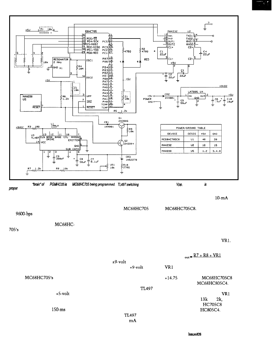
“
I
R S - 2 3 2 G N D
MAX232
.
I
P O 7
PC7
3
PCS
R S - 2 3 2 O U T
P C 4
2 R S - 2 3 2 I N
R I
. . .
4
__
+ __
P C 0 i s -
-
22
39
“ E R I F
P R O G
GREEN
PBS
- 9 u
2
CMPINH FREO
Figure
l--The
the
the
A
regulator is used to generate
while a MAX232 used to generate
RS-232 levels.
accuracy of the resonator is more than
adequate for generating the program-
ming timing pulse and the clock for
the
serial interface.
The configuration resistors are
used to select one of the
many programming modes (see
Table 1). I permanently configure the
programmer for to mode 2 using the
resistor networks connected to pins
3134. Mode 2 allows the PC to load a
program into RAM and execute it.
This function enables the PC to set up
the microcontroller to receive data and
copy it to the internal EPROM.
The
reset line is
controlled by a Maxim MAX698 POR
(power-on reset) chip. This chip senses
the level of the regulated
supply and provides a controlled reset
(active low] output. The reset output is
delayed by an internal
timer
during power up and is immediately
switched to reset during power down.
The timer provides enough time for
easily supply the less than
the programmer’s Vpp voltage to
programming current required by the
stabilize before the
is
brought out of the reset state.
Designing with a switching
The RS-232 interface used for
regulator isn’t always obvious, so I
downloading data uses an inexpensive
thought I’d go over how I came up
MAX232 transceiver chip and four
capacitors. The MAX232 eliminates
two power supplies and regulators
from the design at the expense of the
four small capacitors required for the
internal switching supply. The chip
also provides
outputs for
external circuitry. The
output
is connected to the microcontroller’s
l
IRQ pin to enable the programming
circuitry inside the chip.
To generate Vpp, I use a
switching regulator. While this part
may not be the latest and greatest, it is
inexpensive, easy to find, and requires
only an inductor and some resistors
and capacitors. The
is capable
of supplying up to 500
and can
with the component values I used. The
output voltage is set by the resistor
divider formed by R7, R8, and
The output voltage is determined by
V
1000
provides a limited adjustment of
the voltage, allowing Vpp to be set to
volts for the
or
+ 19 volts for the
If
only one type of part is to be pro-
grammed, the value of R8 and
may be changed to
and
respectively, for the
or to
16k and 5k for the
The
current limiting in the supply is
provided by R6 and serves to limit the
The Computer Applications Journal
April/May,
1992
6 3
inductor current as well as the output
current. Determine the peak inductor
current using
= 21
In the equation above, is the
maximum output current and is set to
10
is the peak inductor
current, and and
the output
and input voltage, respectively. The
value of will be used to determine
the current-limiting resistor. Substi-
tuting 33
for in the equation
that determines the value of R6 yields
R6
0.5 v
0.033 A
The calculated value of R6 is 15 I
then decreased the value of R6 to 10
for a little more margin.
The inductor used in the supply is
a
part from Toko and is
available from Digi-Key. Due to the
light output loading, almost any value
Mode Pin 31 Pin 32 Pin 33 Pin 34
Operating Mode
G N D G N D G N D G N D
Program and Verify from an external EPROM
1
G N D G N D G N D V C C R e s e r v e d
2
G N D G N D V C C G N D
Load Program to RAM and run program
3
G N D G N D V C C V C C
Reserved
4
GND VCC GND GND Verify EPROM against external EPROM
5
G N D V C C G N D V C C
Secure EPROM Verify against external EPROM
6
G N D V C C V C C G N D
Dump Contents of EPROM via RS-232 interface
7
G N D V C C V C C V C C
Secure EPROM and Dump contents via RS-232
8
V C C
N/A
N/A
Execute program in RAM at location $0051
Tabb
l--The
modes,
ty
pins on
high
inductor in the range of SO-500
I chose a value for
to provide
will work. The current handling
an output ripple of less than 50
capability of the inductor should be at
millivolts at a typical load of 10
least 100
to prevent saturating the
To determine the value of
use the
inductor during current peaks.
following:
A
timing capacitor was
chosen to provide an on time of about
32
This standard value is within
T
ON
the operating range of the part. At the
low current the programmer requires,
almost any value of capacitor in the
Assigning a typical load of 10
to
range of 200-2000 should work, but
and substituting the calculated value
the value of
will change based on
of in the equation for the output
the resulting on time.
capacitor yields
MAGNUM OPUS
ELECTRONIC ENGINEERING
SINGLE BOARD COMPUTER
l
includes
RAM -Supports 640K
BIOS R O M
l
4.77 MHz, 8 MHz Operation
l
Parallel Port
l
Clock
8087 Socket
Keyboard Port
l
Model #XT-640R
l
Speaker Port
l
Includes 8 Slot Passive Backplane
C
l
Plugs
into PC, XT, AT
l
BASIC Interpreter
2716-27010 EPROMS
l
RAM,
EPROM
l
Bit EEPROMS
l
On Board EPROM Programmer
. NMOS, CMOS
. Serial
l
Includes Software
l
24 Parallel
Lines
Read, Write, Verify, Copy
. Timers, Interrupts
$195.00 quantity 1
$197.00 quantity 1
Engineering Manufacturing
Analog Digital Microprocessor
Standard Custom Semi-Custom
STRENGTH
SINGLE BOARD COMPUTER
OPTIMUM FEATURES FOR DATA
AND
CONTROL.
DESIGNED AND BUILT FOR TOUGH APPLICATIONS WITH A
2
WARRANTEE AND A DAY
BACK
PROGRAMMING
A
IN EITHER MULTI
-
TASKING
OR
C.
F
E A
TURES
NCLUDE:
*
80PTICALLY COUPLED DIGITAL INPUTS
*
8 HIGH DRIVE BUFFERED DIGITAL OUPUTS
*
PROGRAMMABLE DIGITAL
LINES
*
THIRTEEN BIT ANALOG INPUTS
*
2
OPTIONAL
TWELVE BIT ANALOG
OUTPUTS
*
4 SERIAL
SERIAL PORTS
* 6 TIMER/COUNTERS
*
TO 512K MEMORY
PLUS
E E P R O M
*
E-PAC 3000 G2 COST $389.00
1
inc.
618-529-4525
Fax 618-457-0110
P.O. BOX
2042.
CARBONDALE, IL 62902
The Computer Applications Journal
Issue X26 April/May, 1992
65
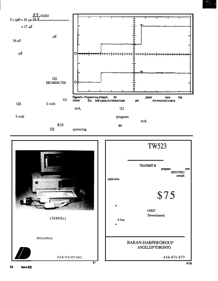
A + 0.010 A
0.05 v
From the equations above, the
calculated value for C8 is 17
I used
a
electrolytic capacitor to ensure
a low ripple under all conditions. In
addition to the electrolytic, I also used
a 0.1
ceramic capacitor on the Vpp
output to provide additional filtering
of any high-frequency switching
transients from the supply.
The Vpp switching is controlled
via the microcontroller’s *RESET line
and a two-transistor switch.
is used
to turn Q 1 on when the
is brought out of reset, which switches
the programming voltage to the
microcontroller. A 3.6-volt zener diode
(CR3) on the emitter of Q2 ensures
and
are off when the
supply
drops below 4 volts. I want to be sure
the programming voltage is off when
the
supply is not in regulation
and when programmed devices are
removed from the programmer.
limits the current through
to about
must applied in sequence during
up. The fop
shows
while the
shows
In
is 5 volts
division and
50 ms par
division.
4
which is enough to force
Power for the board may come
into saturation when it is on. Figures 2
from any wall transformer or power
and 3 show the timing of the
supply capable of providing 9 VDC at
ming voltage with respect to Vcc
150
I put a series diode on the
during power on and power off
board to protect the circuitry against
reverse voltage on the supply line. Do
PC-Based Logic Analyzers
New Prices for 1992
I D 1 6 0
$ 5 9 5
ID161 (100 MHz) $695
*High Speed l 8K Trace Buffer
l
16 timing channels
expandable to 32 state channels *Multi-Level Triggering
*State Pass Counting *Event Timer/Counter l Performance
Histograms *Hardcopy Output *Disassembles S-bit micros
*Supports VGA
*Demo diskette available
30 Day Money Back Guarantee
INNOTEC DESIGN, INC.
6910 Oslo
Circle, Suite 207
Buena Park, CA 90621
Tel: 714-522-1469
X-10
DEVELOPERS KIT!
AT LAST !! Now you can
RECEIVE X-10 COM-
MANDS under control of YOUR application
We supply
with the I-O SOURCE CODE. Be
up and running in
Write your own CLIPPER/BASIC program. We also have
packages. Shipped within 24 hours worldwide.
Phone our BBS for complete pricing and details.
Each
Kit
contains:
X-10 TW523 Transceiver
l
Serial OR Parallel RJ-1
Interface
l
Microsoft/Turbo C I-O
*
cable
Technical Reference Manual
DEALER INQUIRIES WELCOME
a
LOS
VOICE 416-294-6473
B B S
April/May, 1992
The Computer Applications Journal
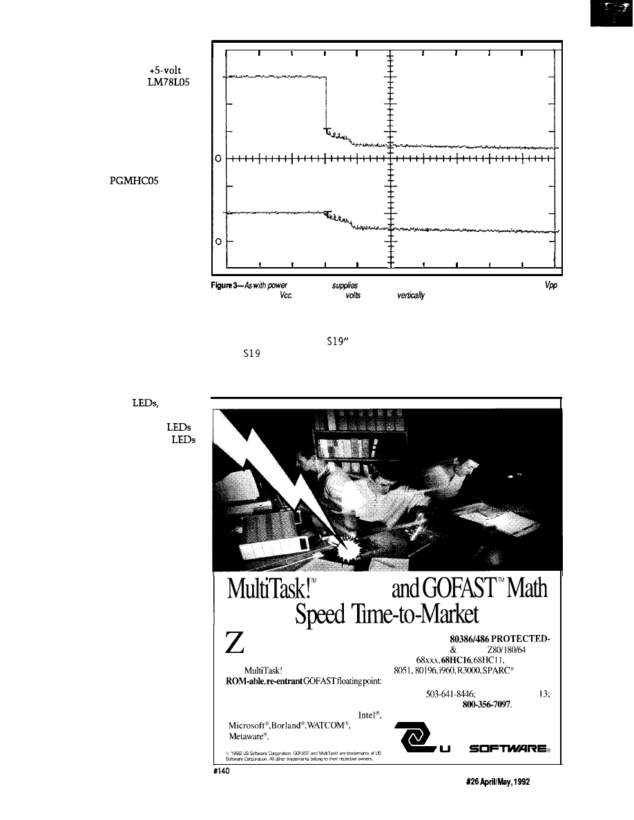
not use a supply over + 12 VDC
because you won‘t be able to properly
adjust the Vpp voltage. The
supply is regulated with an
regulator.
I intended the programmer’s
circuit design to be as simple as
possible. Low-cost and available parts
are used throughout. Most parts,
including the zero insertion force
socket, are available from Digi-Key.
I designed the
me-
chanical layout to simplify the
construction of an enclosure. All
active parts are mounted on what
would be considered the component
side of a two-sided PC board. After
they are soldered in place, the pro-
gramming socket is mounted on the
solder side [I usually mount the
programming socket in a standard IC
socket to get a little extra height above
the component leads protruding from
the board]. This arrangement allows
the board to be mounted in a plastic
enclosure that has a square cutout for
the programming socket and four
mounting holes for the board. A couple
of additional holes for the power
switch, power jack, and
and the
enclosure is complete.
Connections for two status
are provided on the board. These
provide a visual indication of program-
mer operation when the PRO G7
software package is used. They are
provided for compatibility with the
Motorola board and may be left out if
you’d like because the BURN 0 5
program provides programming status
information via the PC display.
THE SOFTWARE
B U R NO 5 is a basic, no-frills
program that will only do device
programming using a PC as the host. It
accepts a standard S-record file as its
input and bums the program into the
microcontroller’s on-board EPROM.
Typical programming time is about 30
seconds with larger files taking
proportionally longer. BURN 0 5 ex-
ecutes from the DOS command line
and requires no switch manipulation
once the board is turned on and Vpp is
applied to the chip (which is done
automatically by the PGMHC05).
When the programming is complete,
up, the
power
must be sequenced during power down. The top trace shorn
and the bottom shows
The scales are 5
per division
and 50 ms per division horizontally.
the verification status is displayed on
execute programs under control of a
the PC. A typical BURN05 command
host PC. The program is cumbersome
would be "BURN05 TEST.
where
to use when programming parts, and
TEST.
is the S-record file.
programming times are significantly
PRO G7 is a fancier, menu-driven
longer than when using BURN05, but
program used to program, load, and
PROG7 has some extra features not
Execs
a p y o u r a p p l i c a t i o n w i t h p e a k
performance using tested code and
expert support. Control real-time scheduling
with
source code executives, or
*Replace 80x87 MATH COPROCESSORS;
*Drop-in IEEE SOURCE LIBRARIES;
*Link-and-Go with C compilers:
Zortech,
and more..
Solutions for
MODE,
80x86 V-Series,
180,
8085,
6801, 6809,
and more.
Call for free information diskettes today.
PHONE
FAX 503-644-24
USA TOLL
FREE
14215 NW Science Park Drive
Portland. OR 97229
S
The Computer Applications Journal
Issue
6 7
found in its little brother. Among
them,
PRO
G7 can transfer the micro-
controller’s EPROM contents to the
PC, which can be useful for comparing
the contents to a data file or for
making copies of the part.
PROGRAM SOME PARTS
Setting up the programmer and
programming parts is easy. First,
connect the RS-232 port to
on
the PC. Make sure the board power is
off and insert the
in the
ZIF socket. Next, turn on the
programmer’s power (the two
may flash momentarily). Type
“BURN05
f i 1 ename.
on
the PC,
where f i 1 ename. ext is the name of
the S-record file to be programmed
into the part. The PC should display
Complete
of parts and assembled
PC
public domain cross-assembler for the
boards are available from:
PC and
BURN05
(copy charge) for $5.
Single Chip Solutions
Box 680
New Hartford,
CT
06057
(203) 496-7794
Add $5.00 for shipping and handling on
Kit or Asy. Connecticut residents add
sales tax.
Kit-includes all parts (less optional
resistors and
wall transformer and
mating connector, DB-25 connector, and
PC board [no enclosure is available) for
$100.
Motorola Freeware
BBS (512) 891-3733
(BURN05
and
PROG7
software)
Asy-Assembled
PC
board
wall
transformer, mating connector, and
25 connector [no enclosure is available)
for $130.
Corporation
701 Brooks Ave. South
P.O. Box 677
Thief River Falls,
56701-0677
(800) 344-4539
Fax: (218)
the status on the screen as each
operation completes (blank check,
program, and verify). When program-
ming is complete, the final status is
displayed on the screen. Board power
must be off prior to removing the
programmed part from the socket.
FINALLY...
The
is a valuable and
inexpensive tool for the microcontrol-
ler designer. It has proven very useful
when developing microcontroller
programs for my projects as well as for
small production runs of programmed
parts. Now many more system
architects can add a new dimension to
their designs.
q
Edward
is a senior design
engineer with Hamilton Standard and
holds a B.S.E.E. from the University of
Connecticut.
416
Very Useful
417 Moderately Useful
418 Not Useful
Cross-Assemblers
from
Simulators
from
Cross-Disassemblers
from
Developer Packages
from $200.00 (a $50.00 Savings)
Make Programming Easy
Our Macro
Cross-assemblers are easy to use. With powerful conditional
assembly and unlimited include files.
Get It Debugged -- FAST
Don’t
wait until the hardware is finished. Debug your software with our
Simulators.
Recover Lost Source!
Our line of disassemblers can help you recreate the original assembly
language source.
Thousands Of Satisfied Customers Worldwide
has been providing quality solutions for microprocessor
problems since 1995.
Processors
Intel
RCA
Intel
8051
Motorola 6805
Motorola
Motorola 6801
Motorola
WDC
Hitachi 6301
Motorola 6809
MOS
Tech 6502
600
Intel
Zilog 280
Hitachi
Mot.
8,
Intel
N e w
For Information Or To Order Call:
Zilog
Zilog Super8
. All
require an IBM PC
compatible.
716 Thimble Shoals Blvd., Suite E
Newport News,
VA 23606
(804) 873-1947
8
Sockets for Fast Gang
and
Completely stand-alone
Programs
1 Megabit DRAM
User
32 Megabit
RS-23.7
Parallel la and
Flash FFPROM easy
upgrades
Pulse Algorithm 127256
in 5 sec. 1
in
17 sec.)
. Made the A
-Complete
-Single
Socket
also
available. $550.00
.
and Shuffle 16
. 100 User Definable Macros 10 User
. Binary,
Hex. and Motorola
to 4 Megabit
New
Programs
10 sec. 256
1 Meg (27010, 011)
in 2
45 sec. 2 Meg
in 5
Internal card with external 40
Reads.
and programs 2716, 32, 32A.
MCM
4
Automatically
sets
Load and save buffer disk
Intel Hex, and Motorola S formats
modules rewired
1 Year warranty
days
back guarantee
. Adapters
for 8748. 49 51, 751, 52.
TMS
and
cards
. Made S A
EMPDEMO.EXE
BBS (916)
NEEDHAM’S ELECTRONICS
more
4539 Orange Grave
-Sacramento. CA 95841
C.O.D.
FAX
April/May,1992
The Computer Applications Journal
DEPARTMENTS
Firmware Furnace
From the Bench
Silicon Update
Practical Algorithms
Ed Nisley
Infrared Home Control
Gateway
ome folks have
problems in places
where most of us
don’t even have places.
Consider the fate of the poor chap who
fixed Steve’s furnace last week: he
didn’t move around enough to keep
the motion-sensing lights turned on.
The house was on manual lighting
control while the repairman was at
work, if you can imagine that.
Now, suppose everybody in
Steve’s house wore a badge that
broadcast a unique ID. The HCS II
could then track each person and
adjust the room lighting, sound system
volume, security defenses, and so
forth, depending on who was where.
Finally he’d have a truly personalized,
automated house that would work
without manual adjustments.
Of course, the system can only
track people (or, I suppose, dogs)
wearing IR badges. But consider what
the HCS II’s response might be should
the basement door open without a
valid badge ID on either side..
The topic this month is the
firmware needed for an IR gateway to
the new Circuit Cellar Home Control
System II. It receives infrared signals
from remote units and passes them to
the Supervisory Controller (SC) for
action, so you can control the HCS II
without leaving your chair, as well as
transmitting IR signals that can poll
70
issue X26
1992
The Computer Applications Journal
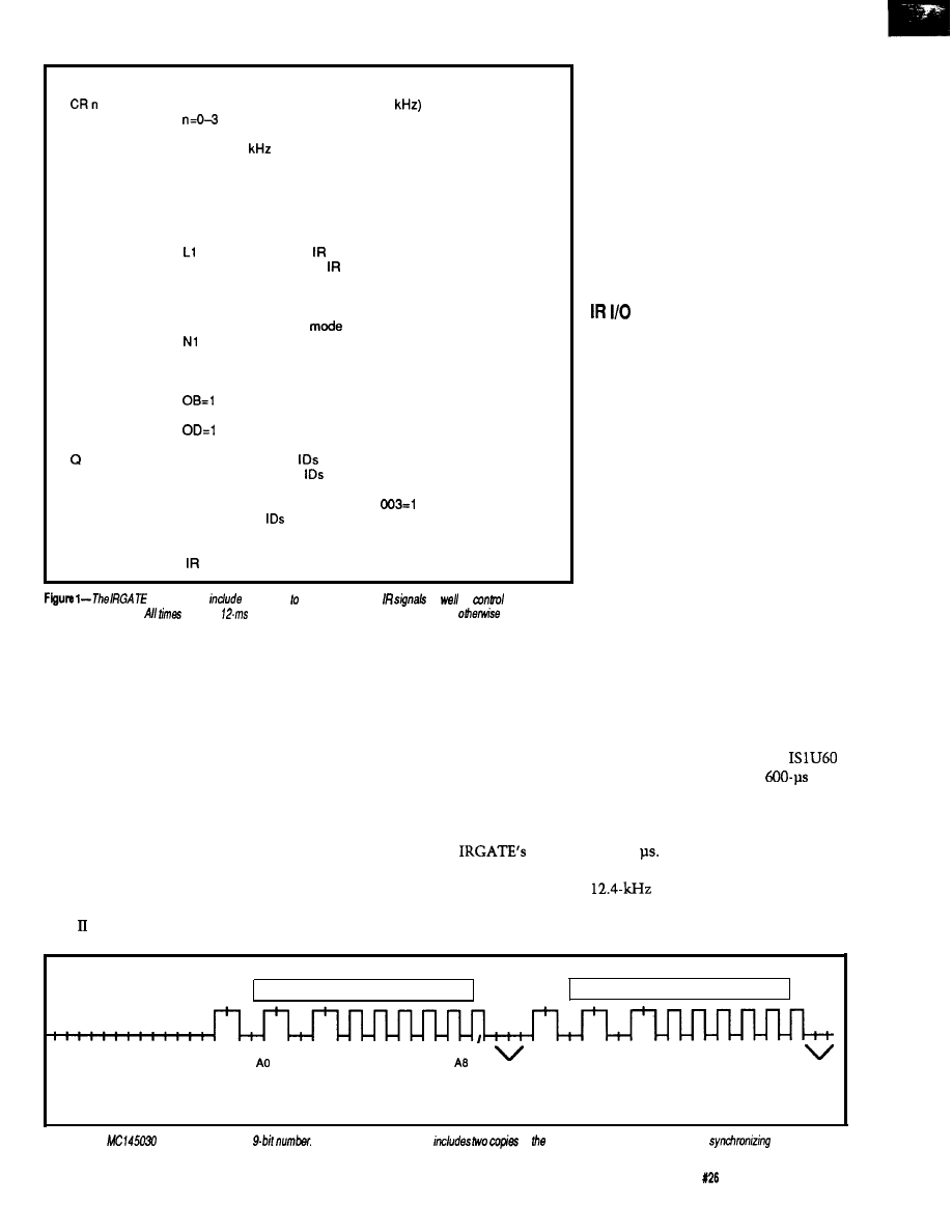
B
Set badge response delay (default 40 ticks)
Calibrate remote
MC1 45030 bit clock (12.4
sets report detail
CT
Calibrate transmitter oscillator
connect 38
output to Tl input
D
Dump program status (debugging use)
E
Show and clear error flags (debugging use)
I n
Set badge polling interval (default 190 ticks)
L n
Set logging mode (bit mapped)
L
report current mode
LO
disable (default)
show received messages
L2
show transmitted messages
L4
show generated polls
N n
Set network/interactive mode
N
report current mode
NO
set interactive
network mode (no error messages) (default)
N2
network mode with command echo
0 x=n
Set output bit x to n
OA=O
set bit A
set bit B
OC=O
set bit C
set bit D
P n
Set number of badges to poll (default 0, no polling)
Query and reset received
a
dump all 512
in hex (130 chars in line)
ID 0 is bit 0 of first byte
Qn
report ID n status in format
On-m
report
n through m in hex bytes
ID n is bit 0 of first byte
RESET
perform power-on reset, must be completely spelled out
S n
Send ID n
commands
functions send and receive
as
as
the
firmware’s operation.
are in 5.
units. and numeric values are decimal unless
noted.
specific “people tracker” badges. An
HCS II system can have up to eight of
these gateways on its RS-485 network,
so you can put a different unit in each
room to ensure adequate coverage.
GATEWAY FUNCTIONS
The overall structure of the IR
Gateway (or IR-Link) firmware
resembles that of the Smart X10
controller (or PL-Link) I described in
the last issue. It receives and transmits
serial information over an RS-485
network, includes a simple decoder to
handle ASCII commands from the
HCS SC, and is written in Micro-C.
I’ve taken a bit of heat for aban-
doning 80.5 1 assembly language in this
column. For the record, about half of
the “Micro-C” source lines for the
Smart X10 and IR Gateway firmware
are actually assembler code, written
using Micro-C’s in-line assembler. As I
continue to point out, C is good for the
overall program logic, but not at all
suitable for high-speed bit banging and
interrupt handlers.
Figure 1 presents
command set. As with the Smart X10
controller, there are commands to send
and receive IR signals as well as
control how the firmware operates.
IRGATE also includes calibration
routines.
Steve’s description of his IR
hardware explains how the various IR
remote units and badges work. He has
the advantage of using the MC145030
chip directly; on the firmware end of
the signal, there is essentially no
hardware at all! As a result, I must
discuss the MC145030 data format in
some detail before explaining how the
firmware transmits and receives it.
Figure 2 shows the MC145030
data format, adapted from the data
sheet. The chip uses Manchester
encoding, which defines two comple-
mentary signals for each data bit;
Motorola calls the pair of signals a “bit
frame” to indicate a single data bit. A
complete message requires 39.5 bit
frame times: 24 frames hold data or
framing bits, while the remainder
provide silent periods before, during,
and after the “real” frames.
Motorola calls the contents of the
message “address” bits because they
think of the MC145030 as a widget to
control a device at a specific address. I
refer to them as “data” bits because
our messages convey information to
the HCS rather than selecting an
address. Fortunately, the bits don’t
care what they are called and do the
same thing regardless of their labels.
Steve chose the bit frame time to
work correctly with the Sharp
receiver, which specifies a
minimum On and Off time. Because a
Manchester-encoded bit frame uses
both states, the minimum frame time
is 1200
Steve picked 1290 us,
which means the MC145030 uses a
oscillator.
Converting an integer (between 0
and 511, as there are only nine data
Massage data
Message data
1
0
1
0
1
0
0
0
0
0
0
0
1
0
1
0
1
0
0
0
0
0
0
0
12
frames of silence
before start of
message bit frames
Sync
Al A2 A3 A4 A5 A6 A7
bits
I
Two frames
1.5 frames
Trailing
of silence
of silence
bit
Figure 2-The
chip sends a sing/e
A complete transmission
of number amid various pauses and
Ms.
The Computer Applications Journal
Issue
April/May, 1992
71
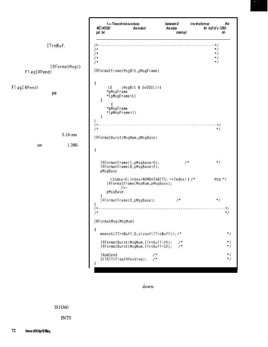
bits available) into a message is
straightforward, as shown by the three
routines in Listing 1. Rather than pack
the output bits into bytes, I squan-
dered 79 bytes of the 8K External RAM
on a C array called
Each
byte holds one bit of the encoded
message, so each array element rep-
resents half of a Manchester bit frame.
Thefinallineof
sets the
ng bit, which is
monitored by a timer interrupt routine
that ticks every 5.16 ms. When it sees
ng set on, it cranks the
timer interrupt to 645 and shovels
bits from the array to the output pin
on each interrupt. After finishing the
message, the interrupt handler resets
the timer interrupt period to 5.16 ms.
The interrupt handler updates
several software timers that count off
intervals of a few seconds. The
motivation for the peculiar
“normal” rate is that it is exactly eight
times the 645 dictated by a
ms Manchester bit frame. After
sending all 79 bits, the code simply
adds 10 counts to the software timers.
This addition keeps the timers
reasonably accurate even if the
firmware sends many IR messages.
Because the interrupt handler
knows nothing about the message
format, the higher-level code can send
any bits it wants. In this application, I
used the MC145030 data format, but
similar code could mimic nearly any
other chip. Such mimicking is espe-
cially valuable when the chip may
change at any time, or when the
requirement becomes “either of these
two remote control chips” after the
first one becomes obsolete.
Sending a message is as simple as
issuing the “S” command to IRGATE
over the serial link. The number after
the “S” must be in the range 0 to 5
11.
The firmware holds outgoing messages
in a ring buffer, so it can accommodate
bursts of commands from the SC or
your program.
BITS FROM THE ETHER
Receiving bits from a remote
MC145030 transmitter is somewhat
more difficult. A Sharp
IR
receiver translates the IR signal into a
‘ITL voltage for the 803 l’s
input
Listing
translate an integer
and 511
required by
chip. Each entry in
array represents
of the
output pin
frame. The entries are transferred to the output by an
handler routine driven by the
chip timer.
Convert argument into Manchester data frame (two
outputs per call)
Uses only low bit of argument to simplify the calls
Output is 1 for "IR On" and 0 for 'IR Off'
unsigned int MsgBit:
BYTE *pMsgFrame:
if ==
= 1:
= 0;
else
= 0:
= 1:
Convert argument into Manchester-encoded burst at ptr
unsigned int MsgNum;
BYTE *pMsgBase:
BYTE Index:
+= 4:
start bits
for
encode
MsgNum
1:
+= 2:
trailing bit
Convert integer into bit pattern in the transmitter buffer
WORD MsgNum:
flush previous bits
first transmission
repeat one time...
= 79:
how many half-frames in buffer
indicate ready to go
pin. The firmware sets up INTO to
when each bit should arrive. The first
produce an interrupt for each
sync bit produces an interrupt in the
going edge, but a little study of Figure
middle of the bit frame that defines
2 will show that the Manchester data
when all of the other bits should
format does not produce an interrupt
occur. The INTO intdrrupt handler sets
for each bit frame.
the hardware timer to interrupt one
The firmware can take advantage
quarter of a bit frame later, in the
of the bit frame timing to anticipate
middle of the last half of the first bit
1992
The Computer Applications Journal
frame, and sets a variable to indicate
that reception is in progress.
The timer interrupt handler then
begins sampling the input and verify-
ing that the data matches the
MC145030 data format. Each sample
must be followed by its complement
(01 or to form a valid bit frame, and
the silent periods (00) must occur at
the right times. During the two groups
of frames holding data bits, the
interrupt handler shifts the second
sample of each frame into a pair of
bit variables.
After the final silent period, the
firmware compares the two variables
to ensure that both data values are
equal. If so, and if all the silent periods
were truly silent, the firmware adds
the data value to the receiver’s ring
buffer for later analysis by the
level C code.
The INTO input continues to
generate interrupts whenever the IR
signal goes on, so the firmware puts
that information to good use. The
timer should be midway in its count to
the next sample at each negative
transition, so the INTO handler reloads
it with exactly one-quarter of the bit
frame time [think about it), which
allows the firmware to track remote
units with slightly off-frequency
oscillators. Timing the interrupts this
way ensures the data samples occur in
the “middle” of each half of the bit
frame, where they are least likely to be
corrupted by noise or timing errors.
Because the receiver and transmit-
ter use the same hardware timer in
different ways, IRGATE cannot receive
while it is transmitting, so, unlike
Smart X10, IRGATB cannot monitor
its own output. The INTO handler
checks the timer handler’s state
variable before clobbering the timer;
the valid state transitions are
and
but
not
or vice versa.
IRGATE records all received codes
in a table that it displays when you
issue the “Q” [query) command over
the serial link. There are several
different formats so you can get the
values you need in the fewest charac-
ters. After sending the table’s contents,
IRGATB clears it so each “Q” reports
only new codes.
BADGE TRACKING
Although
main purpose
is receiving inputs from push-button
remotes to control Steve’s new HCS, I
included all the functions you need to
build a system that can track people
wearing IR badges. Ken’s SC has code
built into it to support active badges
(more in a moment), and allows you
to initiate actions based on what room
a particular badge is in, so the ground-
work is done.
repeat rate to minimize the number of
collisions while not introducing too
much delay in determining when a
new badge enters or leaves the room.
As far as IRGATE is concerned,
there are two types of badges: active
and passive. Active badges are essen-
tially identical to the remote units
described above, except they transmit
their ID code (0 through 5 11) periodi-
cally. Passive badges transmit their ID
only when they “hear” that ID from
another source.
Passive badges, on the other hand,
must include a receiver that is active
continuously, so they will dram their
batteries faster. In addition, IRGATE
must know which badge
to send,
because a passive badge responds only
to its own ID code. While there are no
collisions, IRGATE must poll all
possible badge
to find out which
ones are within range.
I’ll just point out that designing
the badge hardware is not easy and
leave it at that. The receiver and
transmitter hardware used by IRGATB
need the changes Steve describes in his
article to ensure it can cover an entire
room.
Active badges are quite simple,
If your system uses active badges,
because they do not need any receiver
IRGATB needs no changes because it
hardware. However, because each
cannot tell the difference between a
badge transmits without regard for the
remote control unit and a badge. After
others, a room full of badges might
all, there are only 5 12 possible codes
produce no recognizable messages due
and the bits mean whatever you want
to all the collisions. You must pick the
them to. Your controller must poll
Want low power?
Is 10 microwatts low enough?
not for a CPU chip, but for a complete
board in a typical
The automatic
that makes that possible is standard and built-in.)
Fast development?
What
if we write the device drivers for you? And the
low-level
code? And throw in a complete
And a full monitor with source code?
And what if the hardware
all the real-world
you’ll
need, like
buffered digital
and
power switching?
And low cost?
standard board package includes a macroassembler? An
editor? A communications interface? Complete, illustrated technical references
What if the hardware includes a switching supply and even the serial cable?
What if you don’t even need an EPROM programmer?
There a better way.
For
information, call:
(4383282)
(FAX)
A division of
The Computer Applications Journal
Issue X26
April/May,
1992
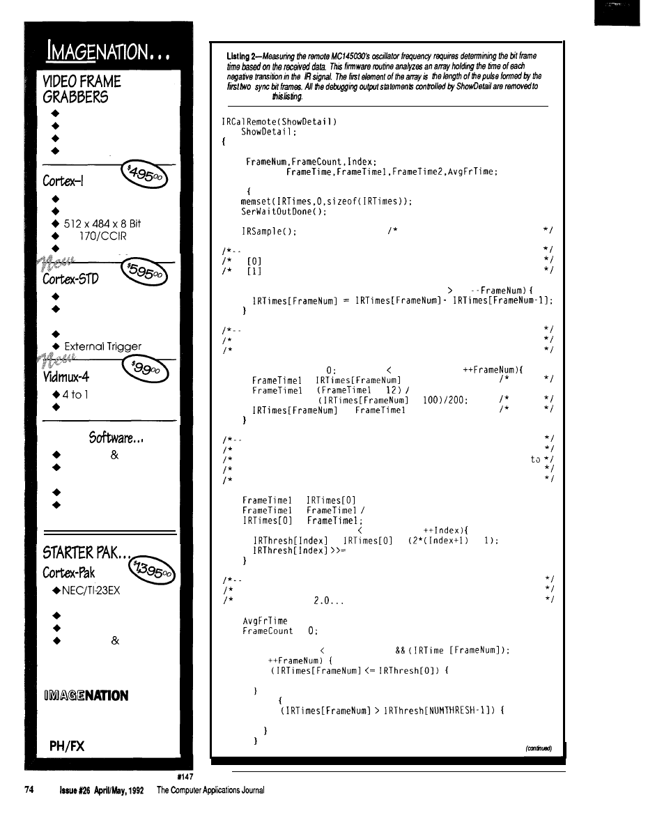
Simplicity
Functionality
Affordability
Accuracy
Real-Time Capture
Half Slot XT/AT
RS-
External Trigger
Dual Video input
Opt. XMS Mapped
l
Low Power Options
STD-80 or 32 Bus
MUX
Half Slot XT/AT
Includes
C Library Source
Image Capture
Utility
Tiff Utilities
“Image” Drive
Ram Disk Emulation
Camera
With Lens
9” Video Monitor
Frame Grabber
Software Cables
OEM PRICING AVAILABLE
CORP.
P.O. Box
84568
Vancouver, WA 98684
(206) 944-9 13 1
save space in
int
BYTE
unsigned int
do
get the IR transition times
get differential time between each sample
is start bit frame time; estimates true frame time
is time since the start. so it is already a delta time
for (FrameNum = MAXIRFRAMES-1; FrameNum 1:
convert times from timer ticks to microseconds
magic number is 1.085 microsecs per timer tick. but we
must do it in two tiny chunks to avoid overflowing 16 bits
for (FrameNum = FrameNum MAXIRFRAMES;
=
* 2:
0.08
=
+
25;
FrameTime =
+
0.005
+=
+ FrameTime2:
1.085
set up initial frame sorting thresholds
this is done in chunks to avoid overflows. too
first frame is special-cased sample. needs 80% derating
real time because the trailing edge is delayed by IR
receiver
=
* 8;
=
10;
=
for (Index = 0: Index NUMTHRESH;
=
*
+
2:
now find the average frame time
determine each interrupt duration
(1.0. 1.5.
bit frame times)
= 0:
=
for (FrameNum = 1;
(FrameNum MAXIRFRAMES)
S
if
continue;
else
if
continue;
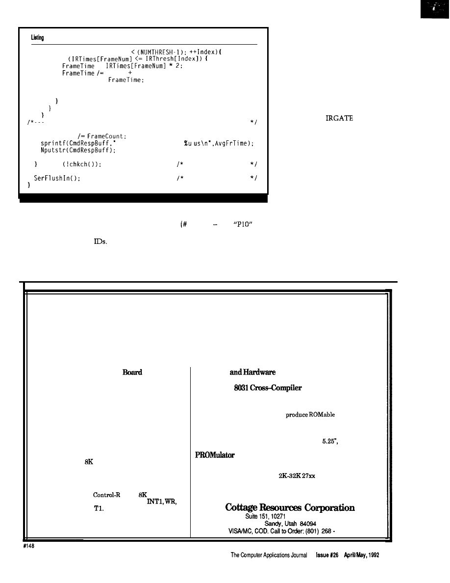
P-continued
for (Index = 1; Index
if
=
Index 1:
AvgFrTime +=
++FrameCount:
break:
figure average frame time and display the result
AvgFrTime
Bit frame time is
while
assume interrupts
discard inputs
IRGATE to determine which ID codes
polling. Polling starts with ID 0 and
have been “seen” since the last poll,
goes up to badges) 1, so
will
and it must also determine how to
poll badges 0 through 9 inclusive. Your
handle new and missing
badges must respond to those ID codes
The “P” command tells IRGATE
for this feature to work!
how many passive badges require
The “I” command sets the polling
polling. The default is “PO,” or no
interval, with the default being two
seconds when polling is enabled. You
should adjust this value to suit your
purposes, taking into consideration
battery life and response time. The
interval is the time between succes-
sive polls, so polling badges 0 through
9 with a 2-second interval would take
20 seconds. The minimum value is 20
ticks, which is about 100 ms.
The “B” command sets the
amount of time
waits for a
badge response after sending an ID
code. The default is 40 clock ticks
[about 200 ms). When polling is not
active, this delay determines the
minimum time between IRGATE
transmissions.
You can use remote control units
as well as badges in the same system if
you choose the ID codes carefully. I
suggest you put all your control codes
in the range 256-511 so the high bit
distinguishes badges from remote
controls and the low byte holds the
entire ID code. If you are using passive
badges, you must allow enough “dead
air” between polls to accommodate
remote control inputs; set the polling
Affordable 8031 Development
Single Board Computers, Assemblers, Compilers,
Simulators, and EPROM Emulators
Control-R Series, Single
Computers
Two
models of Control-R series computers make
prototyping, one of a kind products, or small
production runs easy and economical. Both feature
RS232 compatible serial ports, single 5 volt supply
operation, and direct access to Ports 1 and 3 of the 8031.
Additional features are as follows:
Control-R Model 1 $49.95
Fully populated board with I/O header for Ports 1 and
3, serial port, and
EPROM socket. 3.0” x 4.0”
Control-R Model 2 $79.95
Same features as the
1 plus
of SRAM and
expansion bus with data, address, RST,
RD, PSEN, ALE and
3.5” x 4.5”
Software
Development Tools
Control-C
$200.00
The Control-C 8031 cross-compiler is a full featured K&R style C
development system available at an affordable price. Optimized
for embedded system use, it will
code for any
8051 based system including designs using only the 128 bytes of
internal RAM. Package includes compiler, pre-processor,
assembler, simulator, printed documentation and complete library
source code. Requires IBM PC or compatible.
360K disk.
256 $189.95
An EPROM emulator lets you avoid “Bum and Test” development
cycles. In circuit emulation of
series EPROMs. ABS
Plastic case. Assembled or compiled code is downloaded directly to
the target hardware.
South 1300 East
2875
7 5

interval to
5
or 10 seconds to keep
from clobbering yourself.
CALIBRATION CONSTANTS
Although I describe the signal
as being either “on” or “off” when
transmitting or receiving a message,
that is not quite accurate. The
receiver expects the IR signal to have a
modulation, so an “on” signal
is actually a burst of
IR pulses.
Producing the modulating fre-
quency with firmware isn’t feasible (at
least not while monitoring a serial
network connection!), so Steve added
some hardware to chop the output
signal. But he insisted on a way to
calibrate the oscillator against the
803 l’s
crystal rather
than use a frequency counter or scope.
So IRGATE includes a transmitter
calibration routine that displays the
frequency of that modulating signal.
To use it, just connect the oscillator to
the 8031
input pin, enter the “CT”
command, and tune the frequency.
You even get a simple tuning
graph..
it and see!
Photo
l-The
some time
decide
it is seeing en signal end more time to
that if not
The
shows /he
signal, while
A second calibration routine
again, you’ll see how difficult it is to
sures and displays the remote unit’s
determine this value; remember you
bit frame time. The nominal value is
don’t get an interrupt for each frame
1290 us, but if you study Figure 2
and you don’t know what the data is!
Introducing the Most Expandable 3
Board Available
from $149.95
On Board Options Include:
16 Channels 10 bit A/D
w/S/H
Dallas 1287
Flexible mem config’s: RAM
ROM
KB
RS-232 or 485 -jumper selectable
Watchdog timer
jumper
reset source
Pre decoded external bus for very easy user interface
compatible with other ADS
(see back issues of Circuit Cellar INK)
More I/O modules are
Call for our FREE
today!
(404)
Atlanta, GA 303
18
Issue X26
1992
The
Computer Applications Journal
Basic Compiler._
assembly and C irritation
*Long-lasting relief of time and
budget headaches
*Maximum strength error
handling
Fast integer
BASIC-52 or stand-alone
outstanding technical support.
extensions $149
Assembly Language Toolkit $149
FAX:
76
My first inclination was to
measure the pulse produced by the
first two sync bits, which looks like it
should be exactly one bit frame long.
Unfortunately, the
cannot
switch instantly, because it requires
some time to decide that it is seeing an
IR signal and more time to decide that
it is not. Photo 1 is a magnified view of
a few IR bursts to show the
response time.
I finally realized that the time
between successive negative transi-
tions of the IR signal must be .O, 1
or 2.0 bit frame times, so the code
could extract the frame time without
knowing the data values. The trick is
to use the length of the initial sync
pulse to estimate the frame time, then
classify each transition time and
compute the average frame time. The
code in Listing 2 does just that.
Because Micro-C does not yet
implement long integer
variables, some of the computations
are more laborious than you might
expect. As an exercise, compute the
frequency (near 12400 Hz) from the
average frame time (near 1290 us)
without either overflowing 16 bits or
discarding most of the significant bits.
RELEASE NOTES
The
BBS files this time include
I RGAT . HEX, which is the EPROM
data for the full-function IR gateway
firmware. The source code for
I RGAT E . HEX is available for licensing
from Circuit Cellar Inc.
Also included are the Micro-C
source files needed to create
I RMON . HEX, which is a receive-only,
nonnetworked version of IRGATE. It
will report all the MC145030 codes it
“sees” and includes the calibration
function needed to adjust the remote
unit’s oscillator to 12.4
You can
use this code as the basis for receiving
and decoding other remote control
codes, if you are inclined to use a
different chip.
Next time, a networked Home
Control System LCD panel and
keypad, so the HCS II Supervisory
Controller can show you what it’s up
to and you can give it suggestions.
q
Ed Nisley is a Registered Professional
Engineer and a member of the Com-
puter Applications journal’s engineer-
ing staff. He specializes in finding
innovative solutions to demanding
and unusual technical problems.
Please see page 3 1 for more
information about the availability
of HCS II components.
Software for this article is avail-
able from the Circuit Cellar BBS
and on Software On Disk for this
issue. Please see the end of
in this issue for
downloading and ordering infor-
mation.
419 Very Useful
420 Moderately Useful
421
Not Useful
n
Memory mapped variables
In-line assembly language
option
n
Compile time switch to select
805
1 or
Compatible with any RAM
or ROM memory mapping
Runs up to 50 times faster than
the MCS BASIC-52 interpreter.
Includes Binary Technology’s
1 cross-assembler
hex file
Extensive documentation
Tutorial included
Runs on IBM-PC/XT or
n
Compatible with all 8051 variants
603-469-3232
FAX: 603-469-3530
q
Binary Technology, Inc.
Main Street .
Box 67
l
Meriden, NH 03770
The Computer Applications Journal
Issue
April/May,
1992
7 7
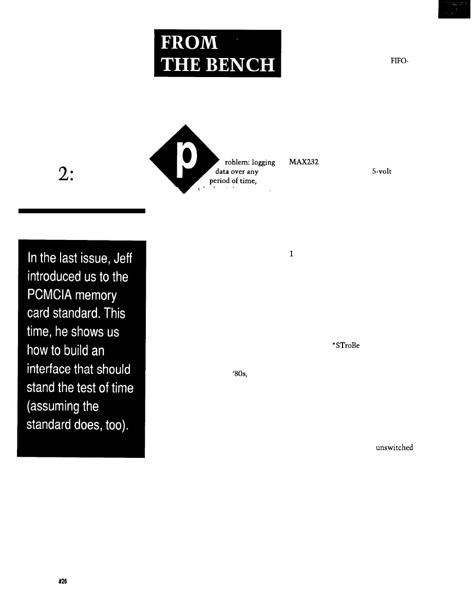
Does It
Come With
a Memory...
Standard?
Part
The Nitty-Gritty
Jeff Bachiochi
whether it be tempera-
ture patterns, device status, or caloric
intake, often requires more storage
space than an inexpensive micro-
controller has to offer. I needed a
simple way to extend the amount of
data I could gather and provide a
semipermanent record of that data.
Solution: Although disk storage is
not rugged enough for many environ-
ments, it does have the advantage of a
removable, semipermanent medium.
Nonvolatile memory devices over-
come the environmental problems
associated with disk storage, yet still
provide “shirtpocket” transportation
and archiving of data.
In my last column, I revealed the
arrival of a new interface standard for
solid-state memory cards. Although it
had its start back in the
this
standard never took off [like it should
have) due to a lack of interface specifi-
cations. After a bit of refinement and
functional diversification, the hard-
ware specifications include I/O devices
as well as the original memory
interface. Software that recognizes and
takes full advantage of attached
devices is still under development at
the upper layers, but using the inter-
face at its lowest levels with assorted
memory cards requires little effort. I
believe that designing with the
PCMCIA interface will extend the life
of any project by ensuring compatible
memory cards do not become obsolete.
A DROP IN THE BUCKET
The term
bit bucket
has come to
mean a place where unused data is
tossed, gone forever, like a write-only
device. However, this project brings
new meaning to the term, allowing
you to retrieve all the data in a
like fashion. The design includes a
micro (8031) with five additional
latches to increase the normal 64K
data space associated with most 8-bit
micros to a possible 64 megabytes. See
Figure
1
for the schematic.
Data I/O is handled in both of the
traditional methods available to most
host systems: serial and parallel. An
RS-232 serial port is supported using a
for level conversion. (This
dual transmitter/receiver
converter replaces a 1488, a 1489, and
a bipolar supply.) Data is transmitted
or received at a predetermined data
rate of 9600 bps [or any other rate of
your choice) with no handshaking
necessary. This rate results in a storage
routine that must be completed within
one character reception time or about
ms (at 9600 bps) or data will be lost.
Also, the host must be able to digest
the data being played back at this rate.
Parallel data transfers have two
advantages. The first is the number of
data paths used. While serial has a
single path or bit stream, parallel has
eight paths or a byte stream. This
difference can mean higher through-
put. The second advantage is hand-
shaking. The
and
l
Acknowledge play a “please and
thank you” game to ensure good data
transfers using two additional control
lines.
Supporting SRAM modules up to
64K is a simple and direct task. Going
beyond the 64K limit of an 8-bit
micro’s address range requires bank
switching. In most bank-switched
applications, only part of the total 64K
data space is switched. An
portion of RAM is used for variable
storage, while the remaining part is
switched; a nice boundary of, say, 32K
might be used. Because this
microcontroller has nothing to do but
store and retrieve data, and the
variables and stack all fit within the
803 1, I can bank switch the total 64K
of (data) space. In fact; an 8751 could
be used, which would eliminate the
need for an external EPROM. The total
code is a few hundred bytes.
78
Issue
April/May, 1992
The Computer Applications Journal
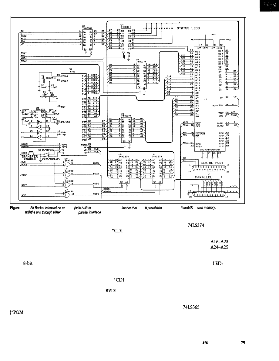
PORT
l--The
8751
EPROM) and several
make
address more
of
Data may be
exchanged
a serial or a
SECRET INGREDIENT
There are no secrets here. The PC
Memory Card International Associa-
tion has the hardware well docu-
mented. The interface to the PCMCIA
card socket consists of 26 address
lines, 16 data lines [I’ve chosen to only
use an
data path), 5 control lines
into the socket, and 6x status lines out
of the socket.
The five control inputs are as
follows:
l
CEl and
l
CE2 are chip
enables (one for the lower 8 bits of data
and the other for the upper 8 bits when
using a 16-bit path].
l
OE is the output
enable and WE is the write enable
for programmable devices).
l
REG is the alternate memory area
normally set aside for device recogni-
tion.
used to indicate when the card is fully
The six status lines are configured
inserted. [Last time, I mentioned the
as follows:
and *CD2 are
unique arrangement of multilength
contacts used in the interface socket.
grounded lines (within a memory card)
The longest pins apply power to the
memory card first, the medium pins
connect all signals second, and the
shortest pins,
and
l
CD2, are
used to signal the card is fully in-
serted.)
and BVD2 indicate the
state of the battery and whether the
data held within the memory card
could be corrupt. WP reflects the
status of the write protect switch on
the card. RDY/*BSY is used by pro-
grammable memory devices to relate
the status of the programming cycle.
space]. Address lines
are held
in the first latch and
in the
Two
8-bit registers are
second latch. The remaining 6 bits of
used as address latches for the address
the second latch are used for LED
status indicators. The
reflect the
lines above the stock AO-A15 (64K
status of the battery in the SRAM
memory module, the write protect
switch, the memory card insertion
detection inputs, the address pointer
(end of RAM), and storage or retrieval
activity. See Figure 2 for an explana-
tion of each LED.
A
6-bit input buffer
reflects the output logic levels from
the PCMCIA’s interface adapter. The
status outputs include battery status,
write-protect switch position, memory
The Computer Applications Journal
issue
April/May, 1992
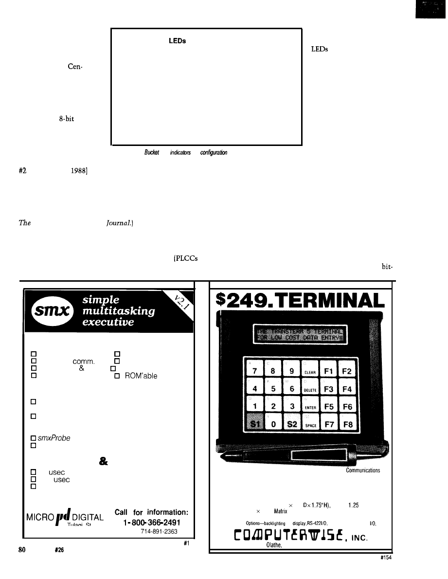
card insertion detection,
and ready or busy for
programmable devices.
The two remaining
latches set up a
tronics-compatible parallel
I/O port. Two external
interrupt lines are used as
handshaking for the port.
(Note: most PC parallel
ports are not
bidirec-
tional. Some discrete ports
can be altered to tristate
the output latch with an
Front-Panel
LED7 On
End of RAM, data transfer halted
LED6 On
Cannot record, card is write protected
LED5 Off
Low battery, system halted
LED4 Off
Data corrupt, system halted
LED3 Off
No memory card installed, system halted
LED2
Toggles with each data byte transferred
easier to work with,
cheaper, and able to drive
directly.
Rear-Panel Switches
Push Button1
Transfer enable
Switch1
Record/Playback mode
Switch2
Serial/Parallel mode
unused chip select. See
Figure
2-M
LED
and
switches.
Circuit Cellar INK,
issue
[March/April
for the printer
port modification used in the all too
famous “Circuit Cellar Neighborhood
Strategic Defense Initiative.” This
“cut and jumper” fix has been used in
a number of projects discussed here in
Computer Applications
If you
have a bidirectional parallel
port, you can handshake data both into
and out of the bit bucket. If you have a
unidirectional port, parallel data can
be saved, but you’ll have to use a serial
connection to “suck” the bits back out
one at a time.
Just about any micro can be used
in this project. I chose to base it on an
803 1 because of its built-in UART and
the availability of a 44-pin PLCC
package. (If you really need to combine
functions for an even smaller design,
there is an 875 1 PLCC version.) The
latches can be replaced with a couple
of 8255s
available here, too),
but I think you’ll find the latches
THE FIRMWARE
If you’ve been follow-
ing this column for a
while, you know my
language of choice is
BASIC whenever possible.
It’s quick to write, easy to
follow (even without
comments), and its
execution speed usually
isn’t a concern. This time
speed is top priority. The
serial reception won’t wait for any
slow code. (Multiple characters will be
received in the time it takes BASIC to
execute one line of code.)
There are only three routines
written for this project. The first is
initialization code to get the 803 1
ready for the task at hand. Here I give
myself some breathing room by
moving the stack pointer up to 21H.
I’m not using all the registers below
the stack, but I do want to use the
FULL FEATURED KERNEL
task manager
intertask
memory manager
error manager
i/o, events, timing resource manager
preemptive
EASY TO USE
libraries for Microsoft C, Borland C/C++,
Zortech C/C++ and assembler
Quick Start, User’s Guide, and Reference
manuals
q standalone, PC, and DOS platforms
task debugger
6 months free support and updates
FAST SMALL
15
max. interrupt latency
150
typical task switch
8 to 25 KB code size
Ask about our $95 evaluation kit.
6402
Tulagi St.
Cypress CA 90630-5630
FAX
Issue
April/May,
1992
The
Computer Applications Journal
Featuring
l
Standard RS-232 Serial Asynchronous ASCII
l
48 Character LCD Display (2 Lines of 24 each)
l
24 Key Membrane Keyboard with embossed graphics.
l
Ten key numeric array plus 8 programmable function keys.
l
Four-wire multidrop protocol mode.
l
Keyboard selectable SET-UP features-baud rates, parity, etc.
l
Size (5.625” W 6.9”
Weight
Ibs.
l
5 7 Dot
font with underline cursor
l
Displays 96 Character ASCII Set (upper and lower case)
for
20 Ma current loop
302 N. Winchester
l
KS 66062
l
913-829-0600
l
800-255-3739
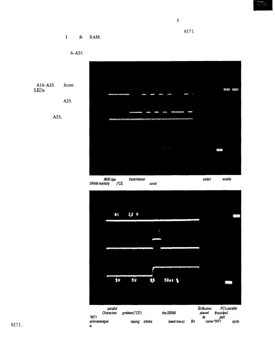
addressable ones starting at byte 20H
for the status information.
The serial port is set up to use an
8-bit data word using Timer in the
bit autoreload mode at 9600 bps. The
internal registers used to reflect the
present state of address lines Al
(bank select) are cleared and the
memory card size registers used for the
end of RAM detection are set up.
Now the first external address
latch is updated from the internal
register with
The
panel status
are on the upper 6
bits of the second external address
latch, which holds A24 and
A
check is made on the status of the
memory card. The appropriate bits are
masked with A24 and
and then
latched into the second external
address latch. If the status is not OK, a
loop is taken back to recheck the
status from the memory card. If all is
well, the transfer enable push button
is checked.
Once the button is pushed, a
check is made on the transfer mode. If
the parallel mode has been selected, a
jump is made to the P-START routine.
If the transfer mode is serial, serial
interrupts are enabled and a check is
made on the function mode. If the
function is record, then jump to
S-START; other wise, the function is
playback, so set the transmit interrupt
(which indicates the transmitter is
empty] and fall into S-START.
S-START
is
an endless loop where code
hangs out while not in the serial
interrupt routine. Setting the TI bit
will cause the serial interrupt to be
entered in the serial playback mode as
will a received character in the serial
record mode.
S-START
(Serial Routine)
A check must be made to deter-
mine the source of the serial interrupt
because there is only one serial
interrupt vector. If it’s from a received
character, then clear the interrupt,
save the character in a temporary
register, and check for the end of
RAM. If the end is flagged, then exit
the interrupt without saving the data;
otherwise, save it to the memory card,
set up the next address, and do a
If the serial interrupt source is
SBU (which will start the serial
from a transmitted character, clear the
transmission), set up the next address,
interrupt and check for the end of
and do a
If the end is flagged, then exit
the interrupt without sending any
P-START
(Parallel Routine)
data; otherwise, retrieve a byte of data
Once thrown into the P-START
from the memory card, place it into
routine, a check of the function mode
Photo 1-A
character
(top trace) is shown in relation to the chip
used to
he
card
bottom trace)
in he
record mode.
Photo 2-The
playback
mode requires hardware handshaking between the
and a
interface.
are
top trace) from
memory card and
info
register.
(middle trace) is lowered, signaling We PC that a character is ready. The PC reads
parallel
and
by lowering and
ifs
line (‘INTO,
The Bucket
and the
repeated for each additional character.
The Computer Applications Journal
Issue X26 April/May, 1992
8 1
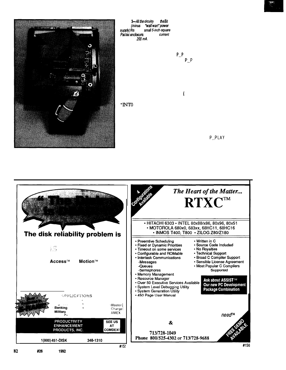
Photo
for
Bucket
he
into a
Operating
is less than
directs execution into the
parallel
record mode
or the
parallel playback
mode.
Like the serial record mode, an
endless loop is entered at P-RECORD
while waiting for a
character. In the parallel
record mode, a character
is ready when the
external parallel port
activates a strobe. The
strobe is tied to the
line on the
microcontroller, which
triggers an external
interrupt. The interrupt
occurs on the falling edge
and a loop is entered that
waits for the rising edge
(an indication of “data
ready”]. If an end-of-RAM
check says “that’s it,” then exit
without saving the data; otherwise, get
and save the data to the memory card
and set up the next memory address.
The
l
INTl line is connected to the
l
ACK pin on the external parallel port.
An acknowledgement signal of at least
5 ms is used to indicate to the PC that
the data has been read prior to RET I .
LAY
(Parallel Play Mode)
LAY is the only routine that
does not use interrupts. This routine
simply checks for the end of RAM and
exits if done. Otherwise, data is read
from the memory card, written to the
parallel output port, and the
l
INTl
line
l
ACKJ is used as the strobe to
signal the external parallel port that
data is available. This time the
external parallel port’s
l
STB line is the
one that acknowledges the data. Once
the *INTO line is seen strobing low,
the
l
INTl line is set [removing the
data available signal). The next address
is set up and the
routine
begins again.
FILLING AND EMPTYING
THE BUCKET
Transferring serial data at 9600
bps requires a fair amount of overhead.
widespread.
There an Alternative!
Dust,
moisture and vibration kill rotating disks every
day. Instant
No
solid state
memories offer extremely high reliability, light speed
access and hermetically-sealed data integrity.
Instant Access is available in
FLASH EEPROM
and NVRAM and is programmable in DOS or
WINDOWS. Rely on Instant A c c e s s - t h e
demonstrably superior No Motion Memory.
Mission Critical Mobile
VISA
High Security
Diskless PC
Hazardous
Environments
Communications
26072 Merit Circle, Ste. 110
l
Laguna Hills, CA 92653
l
FAX (714)
Issue
April/May,
The Computer Applications Journal
Real-Time Multitasking Executive
One Time License Fee From $995
Discounts for Multiple Licenses/Ports
The only real-time kernel you’ll ever
A.T. BARRETT ASSOCIATES, INC.
11501 Chimney Rock, Houston, TX 77035
F A X
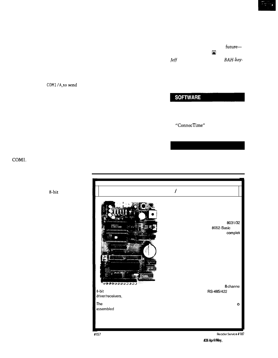
Two additional bits are sent in
addition to the 8 bits of data: a start bit
and a stop bit. Forgetting that this
transmission is in reality 10 bits for
each 8 bits of data is easy to do. At
9600 bps, that’s 960 characters of data
per second or 57,600 characters per
minute. The bit bucket meets these
ideal transfer rates by taking about 68
seconds to transfer a 64K file using a
variety of methods. The simplest is
using a DOS copy command, C 0 P Y
BITBUCK.TXT/B
serial data to the bit bucket. Procomm,
or any similar communication pack-
age, can capture the bit bucket’s serial
output to a file.
A parallel data transfer will be
much faster because data is moving 8
bits at a time. Although handshaking
is employed, and timing depends on
the length of the strobes used, a
transfer rate of 4800 characters per
second can be achieved with the
standard DOS copy command. This
time the file is sent via PRN instead of
Transferring the data from the bit
bucket to the parallel ports requires
two things. First, a bidirectional port
(as discussed earlier) and second, a
routine to make use of the port’s
ability to read back
data. I did not
write an interrupt routine for my PC
to make use of the bidirectional port;
however, I did dedicate 5 minutes to
writing a BASIC program to test the
interface. Transfer was an excruciat-
ingly slow 140 characters per second or
about 8 minutes for the 64K bytes of
data. That’s 13 minutes total to get a
program written and data transferred. I
don’t care how much you may hate
BASIC, if that’s the extent of the task,
it was cost effective. Isn’t that the
bottom line?
FLEXING THE FIRMWARE
Now that you can see the simplic-
ity of the hardware and firmware, you
may wish to take this project to new
heights. A routine to nondestructively
test the amount of SRAM a card
contained could be substituted for the
predefined size selection. Maybe a
two-digit hexadecimal display indicat-
ing the data presently being trans-
ferred. How about the ability to use
other types of memory cards, such as
EPROM, OTP, Flash, or EEPROM?
Each has its own timing and power
supply requirements.
Perhaps you’d like to randomly
place and retrieve data. This aspect is a
tough one for binary transfers unless
your format uses a control word to
define the block of data that follows.
This method could cause problems,
though, if sync is lost between the
control word and the data block. I
would prefer a format in which the
lower nybble holds data and the upper
nybble holds control information. This
way, each byte would pass commands
and data at the same time. Commands
might indicate that the data in the
lower nybble is part of a data byte or is
part of an address to read or write.
The path you decide to take will
depend on your specific application.
Keep in mind, you will end up with a
less universal device if you design a
more complex control format. Univer-
sal is the key word here, no special
transmission codes to interpret, no
special file formats to handle, just
dump your data out and let the bit
bucket do the rest. Once recorded, the
memory card can be write protected
and stored or transported easily from
site to site. I’m betting on the
PCMCIA standard. As for its
well, it’s in the cards.
Bachiochi (pronounced
AH-key) is an electrical engineer on
the Computer Applications Journal’s
engineering
staff.
His background
includes product design and manufac-
turing.
Software
for this article is avail-
able from the Circuit Cellar BBS
and on Software On Disk for this
issue. Please see the end of
in this issue for
downloading and ordering infor-
mation.
.
422
Very Useful
423 Moderately Useful
424 Not Useful
8031 Embedded Controller Development System
A Multipurpose Board for
Embedded Systems or Software
Development
The R-31 board may be used with the
microcontroller or with Intel’s
microcontroller. The R-31 becomes a
development system when used with R-ware.
R-ware consists of an on-board monitor pro-
gram and integrated menu-driven PC-based
host software for edit, assembly, PC-to-board
communications, and debug functions.
Board includes power supply and regulator, up
to 64K of memory using static RAM with batter
back up or EPROM, an EPROM burner (used
with the 8052 basic microcontroller), serial port
up to 12 digital input/output ports, an
analogue-to-digital converter, a battery-backed clock/calendar, 3
line
and a comprehensive manual with circuit diagrams and example software
R-31 is available with various options, with or without R-ware, unpopulated, as a kit,
and tested. Kit prices start at $195.
Rigel Corporation,
P.O. Box 90040, Gainesville, FL, 32607 (904) 373-4629
The Computer Applications Journal
Issue
1992
83
Twenty
Years of
Now What?
Tom Cantrell
t was twenty
years ago today,
the gurus taught the
chips to play, to para-
phrase the Beatles.
Despite my tendency towards
cynicism, I truly give humble thanks
for having been associated with the
micro business. The reason for my
sentiment: the simple bottom-line.
What other business continually offers
more for less?
Consider some analogies compar-
ing various products with the roughly
improvement in microchip
price and performance. How about a
car that goes from 0 to 60 MPH in 1
second, a “four-pounder” burger for 2
cents, or a
foot home for
The cost of “services” is even
more of a joke. For example, today’s
“nonservice” gas station would be
replaced with the real thing-a car
wash, engine rebuild, and shoeshine
while you wait! Need a lawyer or
doctor? Just “buy” one for $100 a year!
I feel sorry for those people who
chose other businesses. Year after year,
they feed their customers apologetic
mumbo-jumbo “justifying” the latest
price increase (the best
whine that your customer is raising
their price, too).
Imagine if I had to approach a
customer with a pitch like, “Here’s the
new 8008x with 0.01 MIPS for only
$10,000.” Ouch!
No, the future looks bright for me
and the micro.
WHO’S ON FIRST?
Currently, the micro is caught in a
custody battle. Who are its rightful
parents?
At the recent Microprocessor
Forum, the ever-entertaining Nick
Tredennick hosted a 20th birthday
“awards” ceremony. Nick is a
known Silicon Valley gadfly, respected
for his blunt (as you’ll see) assessments
of the local high-tech thrills and spills.
If you ever deal with Nick, you’ll
find he is quite an interesting fellow.
First, check out his business card
(Figure
1). Also,
as his signature he
signs the mirror image of his name. All
in all, a real California kind of guy.
Why is Nick this way? I don’t know
and, actually, I’m afraid to ask.
Anyway, the first part of Nick’s
presentation postulates that a “scien-
tific” approach-much like the NFL
quarterback rating system-should be
used to rank the contenders for
“Inventor Of The Microprocessor.”
The foil in Figure 2 pretty much
summarizes his scheme.
is more
your average
consultant.
April/May, 1992
The Computer Applications Journal
Going further (naturally), Nick
highlighted some of the year’s best
headlines:
“U.S.
S
EEKS
W
ORKSTATION
L
IMIT
”
(San
“Pentagon officials,
afraid the computers will be used to
design weapons..
Because the United States is the
leading exporter of weapons, either
this situation is a case of the
government’s right hand not knowing
what its left hand is doing or a
like version of industrial policy. Go
figure.
“P
LAN FOR
MIPS C
ONFUSES
E
XPERTS
”
(New York Times).
Is ACE a Joker? I guess it means
things will work out for MIPS as long
as they don’t confuse beginners (or
themselves).
“W
INDOWS
3, U
SERS
0” (John Wharton,
Microprocessor Report)
Notable quotes of the year were
remembered fondly:
*“We do lots of things with Apple.
We spend billions of dollars on
lawsuits, for example.” (Bill Gates,
speaking at Bay Area Mac Users Group
*“Their last original idea was to
copy Intel.” (Andy Grove, speaking
about the lawsuit between Intel and
*In the
IBM progressed from
the “A:” prompt to the “C:” prompt.
(Jim Canavino at the Agenda ‘92
conference, paraphrased)
Next, the terrified audience (all
fearful they might be singled out for an
“award”) was treated with announce-
ments of:
*Worst-kept Development Secret:
Chips&Tech ‘386
*Time From First Rumor To
Delivery:
*Best Self-induced Setback:
Software Patents (Hey, come on Nick,
it’s not too late for law school)
Finally, he closed with the
perennial favorite:
postulates
that a
should
used to rank the
‘inventor The
Inventor
Ratina System
l
Patents Patent Priority
l
Commercial Products
l
Publications Publication Citations
. Relevant
Experience
l
Professional Acceptance
l
Self Promotion
l
Size of Public Relations Staff
l
Spouse’s Assertiveness
Yesterdav. Today. Tomorrow’s
Technoloav Of Tomorrow
*ward
l
l
l
Optical Storage
l
VHDL
l
CDROM
l
l
Fuzzy
Figun 3-The
of
a moving &get
often hit
much accuracy.
write about 4-bit processors.
*Yesterday, Today, and
I’m glad there is a Nick
row’s Technology of Tomorrow
Tredennick because he has
handedly established a gigantic
(Figure 3)
“irreverence umbrella” under which
minor-league blasphemers can take
shelter from risk-averse editors. I can
Thanks a lot Nick. Now I’ve got
safely “push the envelope” knowing
that Nick has already shredded it,
all my topics for ‘92 and don’t have to
burned it, and spit out the fire.
latest offering; otherwise
you could possibly dismiss it as
bad idea down,” or is there really
another variant of Artificial Intelli-
something more to this fuzzy stuff
gence [AI), which is widely known as
“that which cannot be done by
after all?
computer.”
Let me take a few paragraphs to
explain fuzzy before I delve into
The simplest way to grasp fuzzy
logic is to realize it is quite like the
Boolean logic we know and love,
except that the two values allowed in
that scheme, True and False, are
extended to encompass “multivalues,”
such as Could Be or You’re Ridding.
I’M O.K., YOU’RE FUZZY
“Fuzzy logic” certainly exhibits
some symptoms of a permanent
Technology Of Tomorrow. Two years
ago, I wrote about a fuzzy chip
(Circuit
Cellar INK,
issue
Since then,
little has happened, except that the
company I wrote about apparently
couldn’t wait for the Revenues Of
Tomorrow.
Nevertheless, in the Phoenix-like
way of many high-tech outfits, a new
company-Neuralogix-has risen
from the ashes of the old data sheets.
Is this persistence just another case of
(as Nick might say) “you can’t keep a
That sounds good, but the next
levels of detail, “membership func-
tions,” “singletons,” “alpha cut,” and
so forth, are usually what causes eyes
to glaze over. I’m going to skip all the
theoretical stuff (which is well covered
in the
literature and
academia) and proceed directly to a
real-world example.
Consider the ubiquitous PID
controller. PID, which stands for
Proportional, Integral, Derivative, is a
closed-loop control scheme commonly
used to set a “control output,”
The Computer Applications Journal
Issue X26
1992
8 5
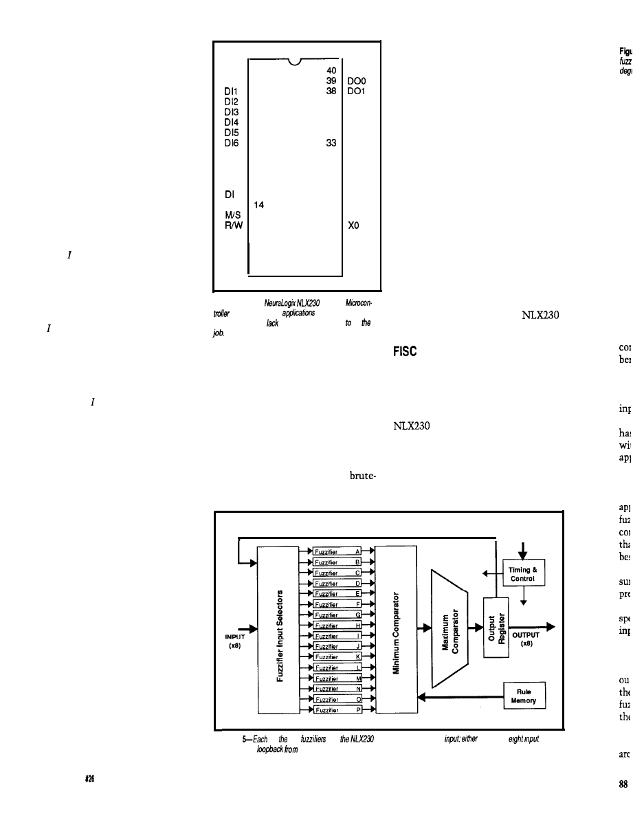
ing on the state of an “error input.”
For example, in a disk drive with an
analog head positioner [i.e., voice coil),
the power applied to the positioner
(control output) is determined by the
error input (i.e., the distance between
the current track and the track being
sought).
PID refers to the three aspects of
the “error” that should factor into the
“output.” They are as follows:
The P term says the output is
simply a function of the current error.
For instance, when using the disk
example, if the track sought is far or
close, apply more or less power to the
head positioner.
The term deals with the “accu-
mulated error” (i.e., area under the
error curve) over time. Imagine your
Brand X drive has some contaminants
fouling the positioner. When it gets
stuck along the way from track A to B,
the term will continually increase
the power until something gives.
RST
1
DIO
2
3
4
5
6
7
8
D17
9
vss
10
SK
11
c s
12
13
DO
15
16
NC
17
NC
18
NC
19
vss
20
VDD
37
DO2
36
DO3
35
DO4
34
DO5
N L X 2 3 0
DC6
32
DO7
31
v s s
30
MAO
29
MA1
28
MA2
27
STB
26
CLK
25
24
Xl
23
NC
22
NC
21
NC
Figure 4-The
Fuzzy
can be
used in
where traditional
microprocessors
the speed or memory do
The D term accommodates
know
“Laplace” isn’t some kind of
“differing rate of change” in the error.
yuppy bar. We whose heads are less
If the head is flying towards track 0
egg-like usually resort to various PID
[perhaps the result of getting unstuck
tuning procedures. Often, in the haste
thanks to the term), the D term will
to get it working, intricate PID tuning
attempt to put on the brakes before
schemes quickly devolve into “play
“terminal overshoot” (i.e., hard drive
around with the dials and see what
seppuku) occurs.
happens.”
PID algorithms are commonly
implemented on micros. Indeed, the
core of a PID loop usually looks
something like
To start understanding the fuzzy
approach to a microapplication like
PID. first consider the ultimate
force approach. Instead of using an
Output = P x (Error) + I x (Error
Integral) + D x (Error Derivative)
where P, I, and D are the “gain”
factors applied to the relevant Error
measure.
Though straightforward, the
software PID approach does have
drawbacks. First, the calculation can
be slow to execute, especially if
floating point is called for. Fortunately,
integer approximation tricks can often
be used, but even then a typical micro
may be limited to a few hundred loops
per second. Second, determining the
optimal gain factors is often nontrivial.
Ideally, the controlled process is
completely modeled to calculate the
required gains; however, this operation
is only feasible for those of you who
algorithm, control is made using a
“look-up table” (i.e., a predefined
memory).
Let me see. Even using only S-bit
integers, I need a memory with 24 bits
of address (8 bits each for the P, I, and
D terms) and an 8-bit output. The bad
news is 16 megabytes of memory is
over $500, even with falling memory
prices. The good news about the look-
up table approach is it is fast-the loop
time is the same as the memory cycle
time (i.e., millions of loops per
second).
The procedure to initialize the
memory with the proper output data
for all 16 million possible input states
is left as an exercise for the reader.
The promise and hope of fuzzy is
to combine the concise representation
of an algorithm with the speed and
simplicity of a look-up table. To see
how it works, take a look the
Fuzzy Microcontroller.
Imagine you had a computer with
an instruction set, including gems like
Branch Maybe and Output Approxi-
mately (should make for exciting
debug sessions!). Fortunately, the
isn’t such a beast, even
though it is named a Microcontroller.
The chip is much simpler than that.
Indeed, it doesn’t have an instruction
set at all. Instead, the NLX230 samples
inputs (eight channels of 8 bits each)
LOOP BACK
INTERLACE
Figure
of 16
on
may be assigned to an
one of he
channels of a
the output.
men
thr
me
64
ass
tin
bit
mc
rul
ma
tht
PA
86
Issue
April/May, 1992
The Computer Applications Journal
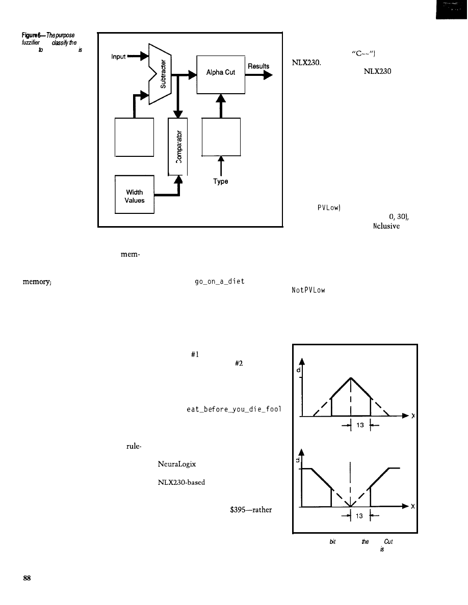
of a
is to
degree which an input a
member of a fuzzy set.
Calculator
Center
Location
Control
Logic
inputs in the same way as rules are
Next comes the minimum
assigned to outputs (i.e., each output
comparator that combines the
has between 1 and 64 rules associated
with it exclusively. One rule can’t
bership info from the fuzzifiers with
apply to more than one output at a
the rules stored in on-chip rule
time).
the NLX230 can hold up to
64 rules. Fuzzifiers are assigned to
Now, assume there are two candidates:
members of a set. For example, say I
1) kind-of-tall, kind-of-wide,
kind-of-heavy
have a rule
IF tall AND wide AND heavy
THEN
2) tall, wide, not-so-heavy
Under the NLX230 max/min scheme,
candidate is the one that should get
like
the message. Of course, may get it
as well, unless there is another rule
IF
tall AND w
THEN
SUCK IT UP
fuzzifier). The remaining 8 bits
comprise the “action value,” the value
that is output from the chip. Actually,
besides direct output, an “accumulator
A rule consists of 24 bits. Sixteen
bits specify which of the fuzzifiers are
mode” allows the output to be the
applied to the rule (each bit specifies a
sum of the action value and the
ide AND not-heavy
previous output. So, each output’s
rules are applied against the the
specified fuzzifiers and their associated
inputs.
Finally, the minimum and
maximum comparators serve to select
the rule whose action value drives the
output. Effectively, this “maximize
the minimum” operation performs a
fuzzy logic sum-of-products (so maybe
they should really call it a “Fuzzy
PAL”?).
Intuitively, what I’m looking for
are the inputs that “least fail” to be
Fortunately, instead of endless air
computing, you can get your hands on
some real hardware and try it yourself.
sells a very nice develop-
ment system (Photo 1) that includes an
PC plug-in board,
download and simulation software,
and excellent documentation. The
whole package is only
a
bargain in my opinion.
So far, I’ve discussed the NLX230
at a machine-language level [i.e., input
selectors, fuzzifier numbers, member-
ship center and width, etc.). A key
portion of the software provided is a
much easier to use “HLL” (maybe
they should call it
for the
An example of an
“program” is one to drive a fuzzy
vacuum cleaner. The goal is for the
vacuum to automatically adjust to
varying operating conditions.
In particular, the vacuum design
monitors three inputs: Pressure, Dirt,
and Texture, and drives five outputs:
Vacuum, Height, Speed, Clean, and
Bag.
The program (Listing 1) starts by
defining 15 of the 16 terms or
fuzzifiers. The format specifies the
input [e.g., Pressure), followed by a
classification name [e.g., Pressure Very
Low
or
associated
with a
center and a width value (e.g.,
and finally, whether an I
or
an Exclusive membership should be
used. Notice how the latter feature
allows easy definition of mutually
exclusive sets. For example, P V L
OW
is
defined as Press u r e with a center of 0
and a width of 30 inclusive, while
isdefinedas Pressure
with a center of 0 and a width of 30
exclusive.
Next, each of the rules associated
with the five outputs is defined. Note
INCLUSIVE
EXCLUSIVE
Figure 7-A type going into Alpha
Calculator
specifies whether he defined fuzzy set considered
inclusive or exclusive.
Issue X26 April/May, 1992
The Computer Applications Journal
that each output can have a different
number of rules; in this example a
total of 25 of the 64 rule memories are
used. The format of a rule is
IF input IS class
input
IS class] THEN output
The first line of each output
definition names the output (e.g.,
V a c u urn), specifies an initial value (e.g.,
and specifies either Accumulate or
I Mmediate output mode for the action
value.
Notice how terms and outputs can
freely allocate fuzzifiers and rules
within the total limits of the chip
(sixteen terms, sixty-four rules]. The
allocation corresponds to the “resolu-
tion” of the input/output. In this
example, Pressure and Dirt inputs are
classified with twice the resolution of
texture (six vs. three fuzzifiers). On the
output side, beater height can be set to
eight levels while the bag-full light is
only on or off (eight vs. two rules).
The NLX230 kit allows you to
simulate operation, download to the
Photo
makes a complete PC-based
system
the
chip for actual execution, or both. As
LET’S GET FRIENDLY
for I/O,
Before fuzzy logic can take off,
digital and digital-to-analog
engineers have to design fuzzy
sion, in addition to digital I/O, are
At least in Japan, from what I
provided.
understand, fuzzy vacuum cleaners,
state-of-the-art in-circuit emulation for
family
processors. Increase your productivity with features like:
l
Symbolic and C Source Level Debugging
l
Pull-Down Menus and Command Line Interface
l
Complete Context-Sensitive Help
l
Real Time Emulation up to 12 MHz
l
Serial Interface works on any PC, even on laptops.
2 1 8 0
H D 6 4 1 8 0
H D 6 4 7 1 8 0
Satisfaction guaranteed with a risk free 15 day trial. Rentals
also available.
or
todav for more information!
We fealure a series of single board computers for
process control applications. Each is available as a
bare printed circuit board, or fully assembled and
tested. Optional development software is also
available. Please contact us to discuss your
requirements and receive a literature package
covering technical specs and pricing.
The Computer
Applications Journal
Issue
1992
8 9
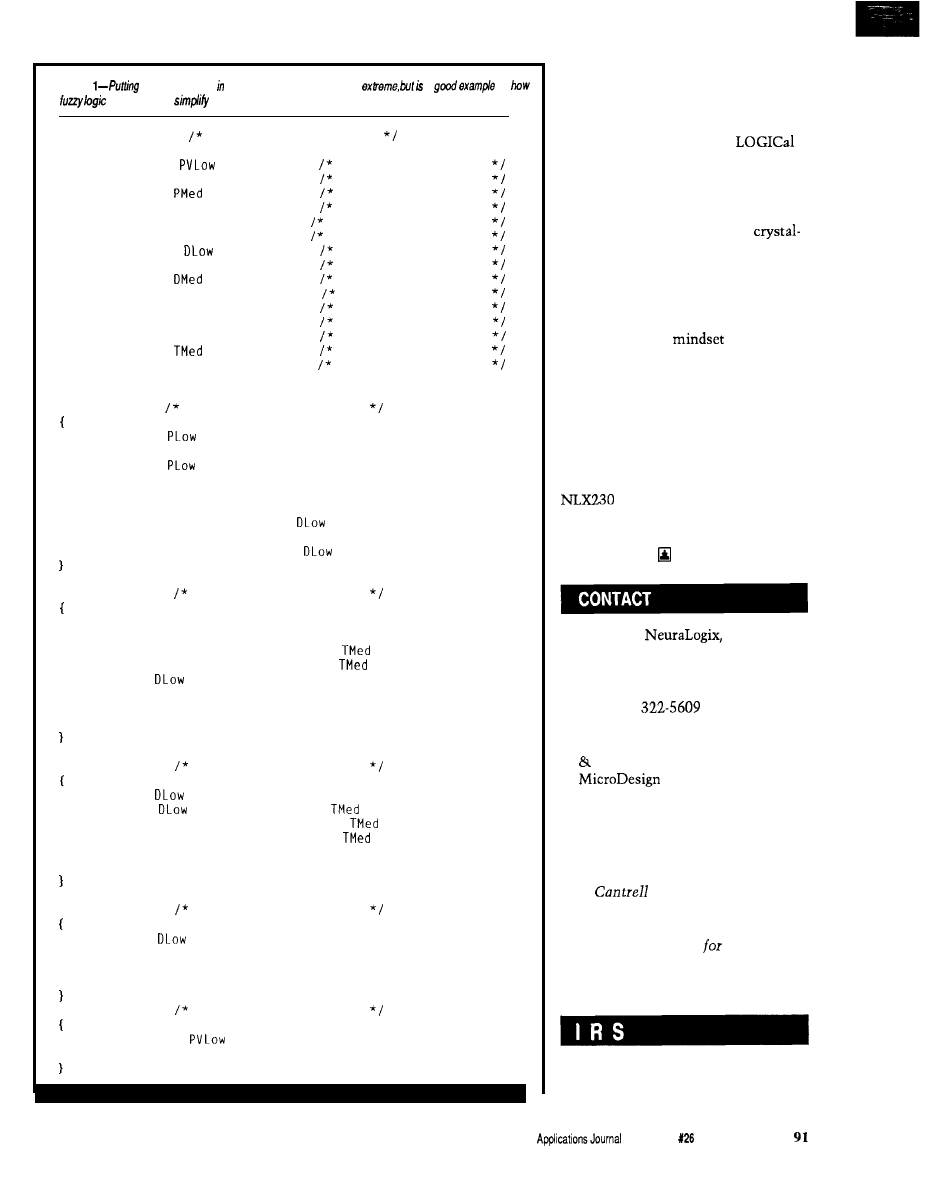
Listing
a microprocessor a vacuum
cleaner
may seem
a
of
can be used to
programming.
NLX230
Vacuum Cleaner Example
TERMS
Pressure
IS
0
30
IN
Vacuum Pressure
Pressure
IS PLOW
40 20 IN
Vacuum Pressure
Pressure
IS
70 20 IN
Vacuum Pressure
Pressure
IS PHigh
90 20 IN
Vacuum Pressure
Pressure
IS PVHigh 135 30 IN Vacuum Pressure
Pressure
IS NotPVLow 0 30 EX Vacuum Pressure
Dirt
IS
0
30
IN
Quantity of Dirt
Dirt
IS DMLow
40 20
IN
Quantity of Dirt
Dirt
IS
70 20
IN
Quantity of Dirt
Dirt
IS DMHigh 100 20 IN Quantity of Dirt
Dirt
IS DHigh
127 20 IN
Ouantity of Dirt
Dirt
IS NotDLow 0
30 EX
Ouantity of Dirt
Texture
IS TSmooth 0
25 IN
Texture of Floor
Texture
IS
30 20 IN
Texture of Floor
Texture
IS TRough 60 30 IN Texture of Floor
OUTPUTS
Vacuum 50 AC Vacuum Control
IF Pressure IS
AND Dirt IS DHigh AND Texture IS TRough
THEN 50
IF Pressure IS
AND Dirt IS DMHigh AND Texture IS TRough
THEN 30
IF Pressure IS PHigh AND Dirt IS DMLow AND Texture IS TSmooth
THEN 10
IF Pressure IS PHigh AND Dirt IS
AND Texture IS TSmooth
THEN 40
IF Pressure IS PVHigh AND Dirt IS
THEN -50
Height 50 AC
Beater Brush Height
IF Dirt IS DHigh AND Texture IS TSmooth THEN 40
IF
Dirt IS DMHigh AND Texture IS TSmooth THEN 30
IF
Dirt IS DMHigh AND Texture IS
THEN 10
IF
Dirt IS DMLow AND Texture IS
THEN -30
IF Dirt IS
AND Texture IS TSmooth THEN -50
IF Dirt IS DMHigh AND Texture IS TRough THEN 20
IF Dirt IS DHigh AND Texture IS TRough THEN 50
IF Dirt IS DMLow AND Texture IS TSmooth THEN -10
Speed
50 AC
Beater Brush Speed
IF Dirt IS
AND Texture IS TSmooth THEN -50
IF Dirt IS
AND Texture IS
THEN -10
IF Dirt IS DMHigh AND Texture IS
THEN 10
IF Dirt IS DHigh AND Texture IS
THEN 20
IF
Dirt IS DMHigh AND Texture IS TRough THEN 30
IF
Dirt IS DHigh AND Texture IS TRough THEN 50
Clean
50 AC
Cleanness Indicator
IF Dirt IS
THEN -50
IF Dirt IS DMLow THEN -10
IF
Dirt IS DMHigh THEN 10
IF Dirt IS DHigh THEN 50
Bag
0
IM
Bag Change Indicator
IF Pressure IS
AND Dirt IS NotDLow THEN 100
IF Pressure IS NotPVLow THEN 0
fuzzy rice cookers, and so on are
emerging.
I think the slow acceptance of
fuzzy logic is inherent in the oxymo-
ron-like nature of the term.
people (i.e., engineers) often don’t
design warm and FUZZY (i.e., friendly)
products.
My coffee maker can automati-
cally turn on at any time with
controlled accuracy. But heaven forbid
if its pot was left in the dishwasher
overnight. No, it doesn’t take a fuzzy
chip to make a coffee maker that
won’t merrily drench the counter. It
does take a fuzzy
on the part
of the designer, though.
Same for the VCRs that take a
Ph.D. to program. The only one I’ve
ever been able to conquer is about 10
years old and features blessedly few
buttons. I think “few buttons” is a key
characteristic of a fuzzy design.
Hopefully, fuzzy chips like the
can speed the availability of
friendly products. Until then, I suggest
you keep a close eye on your appli-
ances-or else!
American
Inc.
411
Central Park Drive
Sanford, FL 32771
(407) 322-5608
Fax: (407)
Microprocessor Report
Microprocessor Forum
Resources, Inc.
874 Gravenstein Hwy. So., Suite
14
Sebastopol, CA 95472
(707) 823-4004
Fax: (707) 823-0504
Tom
holds a B.S. and an
M.B.A. from UCLA. He owns and
operates Microfuture Inc., and has
been in Silicon Valley
ten years
working on chip, board, and system
design and marketing.
425
Very Useful
426 Moderately Useful
427 Not Useful
The Computer
Issue April/May, 1992
Writing
Code to
Support
John Dybowski
Nonvolatile
Memory
flawlessly for weeks.
Now you’ve made the
final code tweaks and you know you’re
going to blow the competition out of
the water. At your presentation,
everyone waits expectantly as you plug
in the new production PROM and
power up the system. Quickly, you
realize that something is wrong. The
system is now making funny noises
and scrolling strange characters across
the display. Sheepishly, you reach over
and reset the system. Same result.
What could be worse? A call comes in
from the computer room, the entire
network is down, choked by a rash of
gibberish from your demo unit. Your
finely tuned, well-crafted creation
resembles some cheap, dime store
novelty. Beads of sweat form on your
forehead as you search your mind for
an explanation.
NONVOLATILE RAM
Used to be, that embedded
systems were simple-minded ma-
chines. They powered up and per-
formed their tasks until power was
removed. Then, reminiscent of some
government officials.. they didn’t
remember. We quickly found that for
many applications, maintaining the
contents of RAM memory in the
absence of power could add features
and open up new applications. Using
the various backup power supply
options available, many people cobbled
up backup protection schemes that
worked reasonably well. More re-
cently, commercial products have been
released that specifically address the
issues of RAM nonvolatility. Close
examination of these RAM
volatizing capabilities indicates many
offer features beyond what can be
attained reasonably using a discreet
approach. Reasonably, that is, in regard
to component count, board space, and
the need for manual tweaking. The
arrival of these reliable, integrated
RAM protection circuits may lull
many people into the belief that the
valuable contents of their
are
secure. Well folks, I hate to rain on the
parade, but it ain’t necessarily so!
Unfortunately, a whole new set of
software considerations exists in a
system that relies on nonvolatile RAM
for its continued successful operation.
Knowledge of the varying levels of
security attainable, and their pitfalls,
are important in the design stages of a
project. All too often, designers
discover the weaknesses in their
systems late in the design cycle when
there is no recourse other than
applying patches to correct the
deficiencies. This solution is usually
difficult because at times problems lay
deep within the bowels of our code.
RAM integrity is compromised in
different ways. An operation may not
run to completion, perhaps only
partially updating some vital control
block. The system can suffer a static
hit or power surge, possibly modifying
some RAM bits. A hit of sufficient
magnitude may even disrupt the
normal sequential operation of the
processor itself, resulting in its
attempt to execute data or to resume
at some arbitrary point of the program.
Should this irregularity happen to be
in the
LEAR
routine, all bets are
off. Obviously, the most desirable
response to such system anomalies is
for some recovery mechanism to put
things straight and for normal opera-
tion to resume. At the very least, you
want the system to detect the error
and either continue to run in a
degraded mode or to remove itself
from operation and possibly issue a
distress call to the host computer.
THE WARM AND COLD OF IT
The first thing you want to
determine early in the power up
sequence is whether the system is
performing a cold or a warm start. On
9 2
Issue
April/May,
1992
The Computer Applications Journal
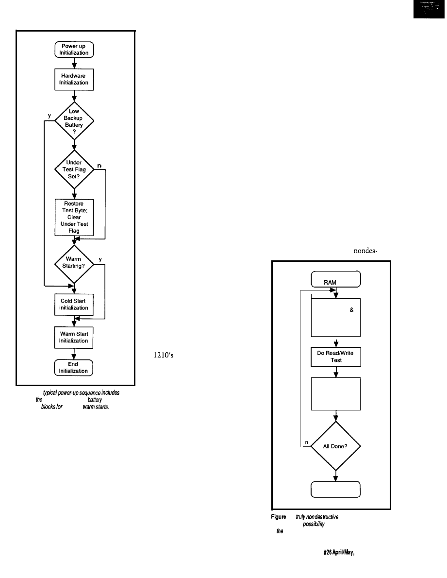
Under
Test Flag
Set?
Warm
Y
Starting?
Figure 1-A
checking status of the backup
and different
initialization
cold and
a cold start anything goes. You can
perform your favorite system diagnos-
tics, go through the rigors of a thor-
ough destructive RAM test, and
initialize the system variables to a
default state before indicating the
system is warm. This denotation may
be accomplished by writing a unique
string to RAM. In some cases, it may
not be performed until receiving the
required configuration information via
download from a host computer or
from some other source.
A warm start is more restrictive.
Most likely you will only want to do a
cursory RAM test and verify the
contents of some critical control
blocks. Of course, it’s a good idea to
check the state of the backup power at
this time. Many nonvolatile RAM
controllers provide a mechanism that
allows easy checking of the backup
battery’s state. The popular DS1210
indicates a low battery condition by
suppressing the second access to the
RAM following power up. What you
actually do when you determine the
backup battery is low depends to a
great extent on the type of backup
power source you’re using. If it’s a
rechargeable unit, then making the
low battery test a part of the cold/
warm determination logic is reason-
able. Of course, if the backup source is
not rechargeable, then you’re dead in
the water and your options are
limited. Figure 1 summarizes what’s
involved in a typical power-up
sequence.
Make sure you don’t overlook the
recovery time parameter when
working with the integrated nonvola-
tile controllers. The recovery time,
implemented in most controller
circuits, is the “dead time” during
which the controller inhibits RAM
access following power up. This pause
allows the system to come under
control before access to the RAM chip
is permitted. For example, the
DS
average recovery time is
specified as 80 ms and can span from a
minimum of 2 ms to a maximum of
125 ms, which is quite a range, and
believe me, you don’t want to be
marginal on this one.
THE NONDESTRUCTIVE,
NONDESTRUCTIVE RAM TEST
In many cases, once a system is
put into service and initialized, it may
run warm for the remainder of its
operating life. Periodically performing
system diagnostics is still highly
desirable, but under such circum-
stances it may not be possible to bring
the system down to do so. Therefore,
diagnostic routines must be devised to
operate unobtrusively and nondes-
tructively. The nondestructive RAM
test, having the right to affect every
byte in RAM, is especially critical. The
general premise behind this test is to
read the contents of a RAM location,
save the contents in a register, perform
some write and read verifications on
the RAM location, and restore the
original data back to its rightful place.
The actual bit patterns used in the
RAM test usually have some special
significance to the programmer.
(Sometimes this preference borders
close to a religious fervor, so I won’t
get in the middle of this one, thanks.)
Of course, the big mistake is to
believe the RAM test will run to
completion! Usually included as part
of the power up sequence, the RAM
test is particularly vulnerable to power
fluctuation problems. Consider a
system dropping in and out of brown-
out. In this case, the RAM test usually
provides a pretty good window on
doing some damage. Thrash a table of
jump vectors or a pointer block and
things rapidly go down hill from there.
For a RAM test to be truly
Nondestructive
Test
Save
Test Pointer
Test Byte;
Set
Under Test Flag
Restore
Test Byte;
Clear
Under Test Flag
RAM Test
C o m p l e t e
2-A
RAM test must
account for he
of
a
power loss in the middle
of test.
The Computer
Applications Journal
Issue
1992
93
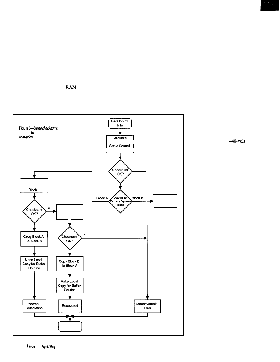
tructive, enough information must be
maintained to allow restoring the right
data to the right location in the event
the test is interrupted before comple-
tion (see Figure 2). This information
may reside in a fundamental RAM
control block and consists of the
address of the location under test, the
value stored at that location, and an
under test flag indicating the location
is indeterminate. For obvious reasons,
you will want to exclude this block
from the area subject to the
test.
The RAM recovery code should be
exercised early in the power-up
sequence by interrogating the under
test flag. Should this flag be set, pick
up the pointer, get the data, and put it
back! You want to do this reset right
after the obligatory hardware initial-
ization, before the cold or warm
determination. After all, you may have
whacked your warm RAM indicator! If
the start happens to be a cold one after
all, this extra step obviously causes no
problems.
THE DIVISIBLE DATA
STRUCTURE
Another problem could occur
when updating fundamental data
structures. Should the processor die in
and redundancy is
one way protect valuable da& against
Checksum over
Block
Calculate
Checksum over
A
Calculate
Checksum over
Block B
Block B
Processing
Complete
the midst of updating a double preci-
sion count or, say, a 16-bit pointer, the
result could be meaningless. The
problem is most aggravated when
using B-bit processors because many of
the elements, such as counters and
pointers, require multiple instruction
steps in their manipulation. Admit-
tedly, the window for such an error is
small. This possibility becomes a real
concern over a large installed base,
especially in the hostile environment
embedded systems seem to find
themselves in and particularly when
doing a lot of data manipulations. A
problem call from the field indicating a
controller once again exhib-
ited some strange phenom-
enon has an unsettling effect
on the current “hot project.”
Of course, they never mention
the guy doing the installation
lashed the thing to a
compressor!
Say you have to keep a
multiprecision running tally
that is critical in nature. One
way to deal with this issue is
implementing dual counters
that are updated in tandem.
You can provide an effective
way of trapping an errant
count by maintaining check-
sums for each counter. The
addition of a flag to indicate
the current primary counter
completes the scheme (see
Figure 3).
This arrangement uses
the following process to
update a count. Calculate the
checksum over the counter
denoted as primary (in
accordance with the current
counter flag). If the checksum
verifies, the count is OK, so
read the counter. (If the
checksum verification fails,
you can fall back to the
secondary counter and try the
same procedure.) Do as you
will to the count and calculate
a fresh checksum. Then store
the count and checksum to
the secondary counter and
mark the secondary counter as
primary. For good measure,
copy the new count and
9 4
X26
1992
The Computer Applications Journal
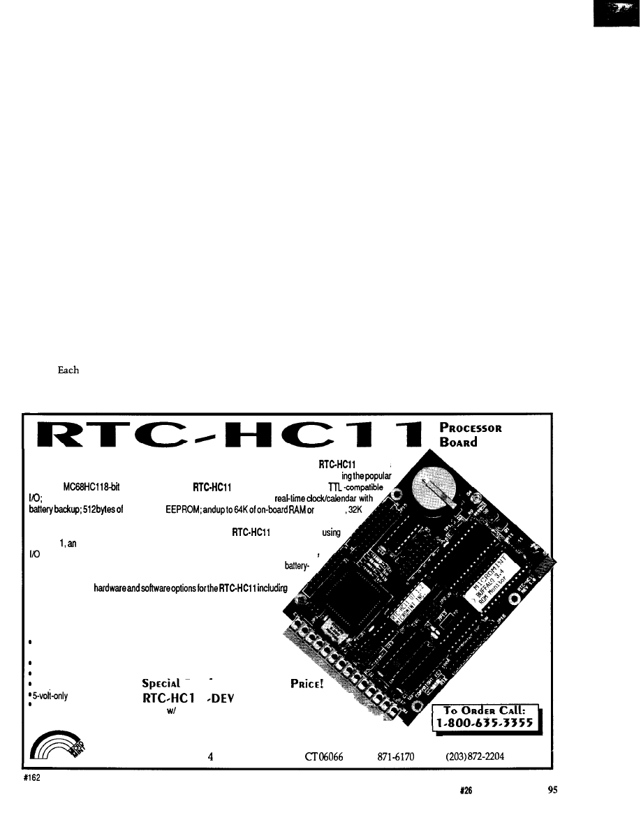
checksum into what is now the
secondary counter in order to have a
valid backup copy.
SECURE RING BUFFERS
Ring buffers are frequently
employed in embedded designs. Often
these are quite large and may hold
collected data that is uploaded to the
host computer either on-line or on
demand. As such, errant operation
may not be restricted to the faulty
system itself, and ultimately may
adversely affect the network commu-
nications and host computer. In a
multidropped environment, the
problem could affect all the attached
controllers as well by disrupting
normal communications. At this
point, I will describe the potential
problem areas and how to safeguard
them.
A ring buffer is implemented by
allocating a linear region of RAM as a
storage area. The bounds of the storage
area are defined by the start and end
pointers.
time a write or read
pointer is incremented, it is checked
against the end pointer. If it has just
incremented past the end pointer, it is
set equal to the start pointer. The
buffer functions in a ring or circular
fashion using these means.
The ring buffer is considered
empty when both the read and write
pointers are equal. For all intents and
purposes, the buffer is full when the
area between the write pointer and the
read pointer is insufficient to hold the
data you wish to store. The success or
failure of the requested operation is
communicated back to the calling
routine via a return code so the caller
can take the appropriate action. The
fundamental operations the ring buffer
must perform are write record, read
record, and remove record. Addition-
ally, an initialization function allows
the buffer to be allocated dynamically
at run time. A check function is useful
to return the empty or full [error)
status of the buffer without actually
doing a read or write operation.
The ring buffer as described
requires two control blocks in order to
operate. First, a static block, written
once at initialization time, that defines
that start point and end point of the
buffer area, the total amount of bytes
available for storage, and the largest
record allowed on a read or write
operation. Second, a dynamic block
that contains the read and write
pointers and the bytes-used counter,
which is modified on each operation
that writes to or removes data from
the buffer.
You can obtain a certain degree of
security simply through the order of
actions you perform when affecting
the ring buffer. For the write operation,
proceed by making a copy of the write
pointer and free space counter, check if
the record will fit, and then move and
delimit the record. The new values are
written into the dynamic control block
once the new value of the write
pointer has been determined and the
free space counter has been recalcu-
lated.
Monkey with the pointers and
other values in the actual control
blocks as little as possible in order to
minimize the amount of time the
block is in an unknown state. There-
fore, all intermediate operations
should be performed on copies of these
Offering exceptional value in a single-board embedded controller, Micromint’s
combines
all of the most-asked-for features into
a
small 3.5’ x 4.5’ package at a reasonable price. Featuri
Motorola
microcontroller, the
gives you up to 21 lines of
an &bit, B-channel analog-to-digital converter; two serii ports; a
nonvolatile
EPROM,
of which can be battery backed.
Software development can be done directly on the
target system
BASIC-1
extremely fast integer BASIC interpreter with dedicated keywords for
port, A/D converter, timer, interrupt, and EEPROM support. In addition, a flexible
configuration system allows a BASIC program to be saved in the on-board,
backed static RAM, and then automatically executed on power-up. Micromint
afsooffersseveral
the full line of RTC-series expansion boards as well as an assembler, ROM
monitor, and C language cross-compiler.
Additional features include:
Asynchronous serial port with full-duplex
RS-232 and halfduplex RS-435 drivers
1 -MHz synchronous serial port
CPU watchdog security
Low-power ‘sleep” mode
D
E V E
L
OPMENT
S
YSTEM
The Computer Applications Journal
Issue
April/May, 1992
operation
RTC stacking bus
1
$300.00
Board B-bit ADC, EEPROM, 32K battery-backed
RAM, Clock/Calendar, BASIC-1 1, ROM monitor, utility
diskette with assembler and complete manual set.
Other configurations also available starting at $239.
MICROMINT, INC.
Park Street
l
Vernon,
l
(203)
l
Fax:
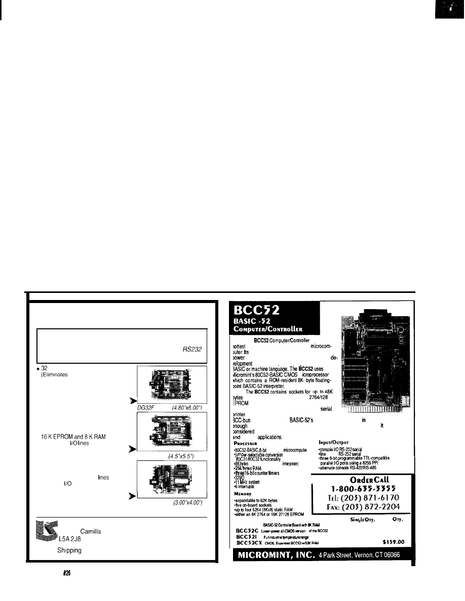
elements. Also, setting a limit on the
As in the simpler data structures,
maximum size for records that can be
written to and read from the ring
you can use dual redundant blocks
buffer is helpful in case the storage
region somehow gets corrupted and
with checksum verification and a
the end of record marks get scrambled.
You don’t want to move a huge block
primary/secondary flag to determine
of data on a read that could overflow
the destination buffer, destroying
whether a block is intact and contains
adjacent areas. This method of han-
dling the ring buffer uses some
valid information. (The implementa-
common sense techniques to reduce
the chance for errors, but further steps
tion details are basically the same as
can be taken to maximize the ring
buffer’s integrity.
for the counter example.) Now you can
incorporate some error traps whereby
problem status can be communicated
to the calling routines by adding more
return codes to the basic buffer
functions.
DATA PREPPING AND ROUTING
At this point, you have reduced
The question now is when the
the likelihood of undetected errors and
provided some redundancy, for fault
data record actually becomes nonvola-
tolerance, in the basic structure of the
ring buffer. Now I will show you how
tile. Consider that the controller has
to structure the code that will actually
deposit and extract the data records.
performed its measurement and now
Consider for my example a hypotheti-
cal system that performs some
has critical data it wishes to dispatch
measurements, writes the measure-
ment data to the ring buffer, and
to the ring buffer. At this time, the
transmits data from the ring buffer to
the host computer on a continual
data is in a work area and if power to
basis.
the system is interrupted the data will
be lost. Worse, the possibility of
insufficient space remaining in the
ring buffer to accept this data record
exists, and I am left with the dilemma
of how to proceed.
One way to handle this situation
is to store the data record in an
intermediate nonvolatile buffer as
soon as it becomes available. A
pending buffer write is then signalled
by the setting of a flag (write pending),
which also resides in a nonvolatile
area in RAM. The write pending flag
can also be interpreted as indicating a
busy condition by the data collection
code, which would inhibit taking more
measurements until the condition
clears. Now the ring buffer manage-
ment code can be centralized in the
mainline loop (or perhaps run as a
task) that polls the write pending flag
and, if set, attempts the write opera-
tion.
After completing a successful
write, the flag is cleared and normal
operation resumes. The simplicity of
this approach handles all write
operations in a clean and consistent
manner. No decision making is
required as to whether I am recovering
from a power interruption, in a buffer
full condition, or just doing normal a
write operation. Actually, a small
PROGRAMMABLE CONTROLLER
803 1
BOARDS
Common features:
l
8031AH CPU,
l
11.0592 MHz clock
speed,
User interface is via a terminal emulator program
running on a host computer and linked through the
Serial Port on the controller board.
K FLASH MEMORY
the need for Programmer
and UV Eraser]
l
16KEPROMand8KRAM
. 32 Buffered I/O lines
Assembled and Tested board $155
Board
l
l
32 Buffered
Assembled and Tested board $129
DG31 Board
l
On board 8 or 16 K EPROM,
8 or 32 K RAM capacity
l
Ports 1 and 3 processor
on 20 pin
headers,
expansion lines on 20 p.
header
Assembled and Tested board $80
EMC32 Board
KITS, Power supplies, Support and Application Software available.
L.S. ELECTRONIC SYSTEMS DESIGN
2280
Rd. Mississauga, Ontario, Canada
Phone/Fax: (416) 277-4893
Terms:
US/Canada $6 Check or
Money Order, Please
The
is Micromint’s
selling standalone single-board
cost-effective architecture needs only a
supply and terminal to become a complete
or end-use system, programmable in
m
of RAM/EPROM, an “intelligent”
programmer, three parallel ports, a serial
erminal port with auto baud rate selection, a
port, and is bus-compatible with the full line of
expansion boards.
full fbating-point BASK: fast ard efficient
for the most complicated tasks, while its cost-effective design allows to be
for many new areas of implementation. It can be used both for development
end-use
CMOS
pat
to
pints
pat
ROM (Ml BASIC
lines
dock
I
To
1 0 0
B C C 5 2
$189.00
5 1 4 9 . 0 0
5199.00
$159.00
5294.00
5220.00
5259.00
96
Issue
April/May,
1992
The Computer Applications Journal
window does exist between the time
the write successfully completes and
the write pending flag is cleared. The
failure mode in this case would not be
a lost record but a duplicate record.
The extraction of data from the
ring buffer is a two-stepped process in
which the read function operates in a
nondestructive fashion and the remove
function must be used to delete a
record from the buffer. Also locating
the outgoing services here is natural
because you have already assigned a
block of buffer management code to
service the incoming data. The process
consists of continually performing
reads on the buffer. If data is returned,
it is posted for transmission to the
host computer and a pending removal
is indicated by setting a flag (remove
pending), which inhibits further read
operations. The remove function is
invoked after the host computer
acknowledges receipt of this data, and
on its completion the remove pending
condition is cleared. Note that for this
process to work properly, the remove
pending flag must always be set to the
cleared state on power up. In other
words this flag must be volatile.
RAM VERSIONS VERSUS
PROGRAM VERSIONS
The situation I described in my
opening remark was intended to be
amusing. However, I must admit it’s
not entirely contrived. While there
weren’t any witnesses, it did happen to
me. Let me explain. The tweaks I
made to the code inadvertently
allocated an extra byte in the RAM
area. This byte was added after the
warm RAM string right in the middle
of system RAM. The RAM, being
initialized, allowed the system to
warm start. Of course, once control
was transferred to the main program,
most RAM references were shifted a
byte and the system got mighty
confused. The only way to get things
back to normal was to force a cold
start in order
to
reinitialize all the
RAM variables to where they were
supposed to be.
Actually the solution to the
problem is fairly simple: make the
warm RAM string the program
number and revision level. Program
revisions will ensure an orderly start-
up. I would also suggest providing an
external means to force the program to
cold start the system in the event of a
catastrophe. This function could be
invoked via a jumper, switch, or by
keyboard from a system configuration
mode. Having a clean way to restart
the system is nice should your defen-
sive coding and elaborate recovery
mechanisms fail. Believe me, you
don’t want to talk your customer
through the procedure of shorting out
RAM power with a paper clip.
Dybowski has been involved in
the design and manufacture of
hardware and software for industrial
data collection and communications
equipment.
428 Very Useful
429 Moderately Useful
430 Not Useful
The Micro-440 is a versatile,
full-featured controller
with an on-board
BASIC interpreter.
Available with
economical
development
packages (includ-
ing
and a wide
range of accessories.
98
April/May,
1992
The Computer Applications Journal
IDEAL FOR HARSH ENVIRONMENTS
Humidity, dust, vibration. shock.
l
4 to 64 Mbytes
l
Seek time. less than 0.2 millisecs
l
Standard AT ISA bus
l
Data retention at least 2 years
l
Fully DOS Compatible
l
Device driver on-board
Business Machine Interfaces Inc.
2 13-05 39th
Ave.,
NY
11361
Canada (4
756-9477
FAX
U.S.
l
800*663+4605
conducted by Ken Davidson
The Circuit Cellar BBS
bps, 24 hours/7 days a week
(203)
incoming lines
Vernon, Connecticut
In installment of
we’re going look at sensing
current in an AC line, the ins and outs of halogen lamps, and some
issues surrounding
You might think sensing current in an AC power line
determine whether a motor is running is a simple matter. Think
again..
From: RICHARD PFEIFFER To: ALL USERS
I am using an RTC52 to control a train horn. I need to
monitor the status of a
1
-HP AC compressor motor. The
AC is always on, but the motor turns off based on the
pressure in the tank. The control switch is a sealed unit and
I cannot get in between it and the motor. What I need is a
way of sensing current in the incoming AC line. I thought
that wrapping a thin wire around one lead in the AC cord I
could sense the current status, but it is too low.
Help. I don’t do op-amps and such. If I were rich I
would just whip out a PC and a GPIB voltmeter and all this
would be simple, but I just need a simple
on/off
signal. If anyone can help I would appreciate it.
From: DALE SINCLAIR To: RICHARD PFEIFFER
There are a few companies that sell items called
“current monitors” for AC power control. I don’t have any
names at my fingertips, but there are plenty of ads in the
trade journals. They work on the same principle you
mentioned, and look like an epoxy donut with wires or pins
coming out of it. They are available in a variety of current
ranges, and some actually have a
output to indicate
current on. Prices are more than you’d think, tens of
dollars, but it’s a good price for what you get.
From: JEFF BACHIOCHI To: RICHARD PFEIFFER
Are there any moving parts on this compressor you can
get at? Use an opto-interrupter or
to sense
movement of the motor shaft, a pulley, or whatever is
available.
From: RICHARD PFEIFFER To: JEFF BACHIOCHI
No,
no accessible moving parts, but a neat idea.
Someone at work suggested I monitor the dam pressure
change, but I’d need a O-200 psi sensor and RTC-IO board.
From: MARC WARREN To: RICHARD PFEIFFER
You might also consider a Hall-effect sensor. These are
solid-state devices that can sense a small magnetic field and
switch on or off depending on the field strength. You could
use it to sense current in the line cord or directly on the
motor if enough field “leaks” out. Sprague and Microswitch
manufacture these
output is available for most
devices.
From: MICHAEL MILLARD To: RICHARD PFEIFFER
What you need is Catalog
from Microswitch
(Honeywell). Their Atlanta number is (404) 248-2565. In
this catalog, you will find exactly what you are looking for.
What is the current range you are looking to measure? (I
may have an extra sample laying around?) Also, do you just
need a comparator output when a preset threshold is
exceeded or do you want a binary output scaled to the
current? Either way, it’s in
Also included are the
Effect devices that others are suggesting.
From: PELLERVO
To: RICHARD PFEIFFER
A word of warning: you may not really benefit from
plain AC current sensing! The current in a motor with an
idle compressor changes very little when the compressor is
loaded. What changes is the phase angle (power factor]. In
other words, there is plenty of current sloshing through the
motor windings even when the compressor is idle, but it is
practically 90 degrees out of phase with the supply voltage.
When the compressor turns on, the phase angle gets much
more in line with the voltage, when real work is being
performed.
The Computer Applications Journal
Issue
X26 April/May, 1992
99
You might need just an old fashioned CT (current
transformer), available from your local electric contractors
or their supply houses for a few bucks. The problem with
them is that they generally produce a
secondary,
while you would benefit from a -ampere or even better
ampere secondary. You can make one yourself. You actually
indicated you have tried, but the missing part was the
magnetic path-a wire alone will not do. And definitely, it
cannot be wound around the motor lead.
What goes around the motor lead is the magnetic core.
Mostly often a toroidal (doughnut) shape, but any closed
path is OK. Then you have a winding of several turns
around that core. In fact, the motor lead can pass the hole in
the core several times as well. What you get is a trans-
former. The ratio depends on the turns just like in any
transformer, but normally you consider the voltages and
then the ratio is direct. In
the ratio is inverse. Let’s say
your primary current is 10 amperes max. Make 10 turns
through the core and you have 100 ampere-turns. Now
make 1000 turns as the secondary. The ampere-turns must
match, so you get 0.1 amperes times 1000 turns to produce
the 100 ampere-turns. Simple?
After the current transformer, YOU MUST HAVE a
load resistor!!! Consider the primary being
V. Your
turns ratio, if there is no load, will produce 23,000 V.
Hardly something you want to happen.
For a 0.1 -A current and normal electronic signal levels
of 5 to 10 VAC, you need a
to
power resistor,
preferably two in parallel, secured directly to the secondary
winding ends, not into some terminal strip far away. You
don’t want the load to ever be opened accidentally.
As to the phase angle detection, you need another
transformer that takes your voltage down to the same or
10-V level. Then you make a zero voltage detector. Finally
you sample the current signal at these zero crossings. It is a
basic principle of it, although an original signal phasing
needs to be provided, but I would need too much space and
some graphics capabilities for all of that.
The
of halogen lamps is increasing every day. Their
benefits over ordinary incandescent
bulbs, including
higher effi-
ciency,
light, and smaller size, add to attraction. how
do they work, and what are some practical issues keep in mind
when using them?
From:
MEYER To: ALL USERS
Here’s a question for you home-control wizards..
I’m using a commercially available photoswitch to
100
The Computer Applications Journal
control an incandescent lamp in my living room (so when it
gets dark outside, the lamp or whatever is plugged into the
switch, is turned on). The lamp I’m using is the type that
takes a 3-way bulb (which may or may not be relevant), but
it seems that at a fairly regular interval, one of the bulb’s
“stages” has burned out and I need to replace the bulb.
(This interval seems markedly shorter than the average life
of the same sort of bulb, so I suspect there’s something
about the way the photoswitch works that is shortening the
life of the bulb.) Can someone explain why this is happen-
ing, and what I can do to prevent it?
Also, I’m thinking of replacing the entire incandescent
lamp with a halogen torchiere, and would like to control it
with the same photoswitch. Are there any reasons why I
shouldn’t use the halogen lamp in this way? And, can I
expect to go through as many halogen bulbs?
From: PAUL PETERSEN To:
MEYER
If your photoswitch is one of the cheap K Mart varieties
you might be stressing the bulb’s filament. I have one in my
kitchen and have noticed in the morning, the light “flick-
ers” a bit just as the sun is coming up and morning twilight
is fading. It’s that very critical crossover point where the
photodetector doesn’t know if it’s dark or light. It only lasts
a couple of seconds but while it’s turning on and off very
rapidly, I can hear the filament in the bulb twanging away.
I’ve wondered if this was good for the filament, but the bulb
is a
20-watt
night light and only burns out after 6 months of
usage...hm...
From: KENNETH SCHARF To: PAUL PETERSEN
I have one of those photoelectric units on an outdoor
porch lamp. It turns the bulb on slowly because the SCR
goes into partial conduction during the period that it isn’t
quite dark yet. Instead of being “digital,” the unit seems to
be “linear,” the photoresistor being part of a divider
network that changes the conduction angle of the SCR. As a
result, the bulb never goes abruptly on or off, and while
going on is “preheated” slowly. I think this extends the life
of the bulb, rather than limits it. (I got over a year out of the
last bulb: a 40-W “bug
So it works both ways...
From: ED
To:
MEYER
The “high” filament has a shorter life expectancy than
the “low” filament, on the assumption that you only turn
up the steam when you need more light. That assumption
is completely wrong for those of us with lights on timers, as
we never touch the lamp switch..
I finally gave up on one of my lights and installed a
standard bulb of the right
works like a champ,
gives off more light, and lasts longer, too. If you’ve got a real
problem, try a rough-duty bulb that will cost more than the
photoswitch...but will continue to work while you pound it
on the floor.
From: KEN DAVIDSON To:
MEYER
Something to be careful of is whether you use a 120-V
or a 12-V halogen lamp. If the photoswitch uses a
to do
the switching, chances are the waveform getting to the
lamp is somewhat chopped. That is fine for a 120-V lamp,
but the low-voltage lamps use a transformer that could be
damaged by the chopped power.
300 K-5.6 micro-ohms/cm
1000 K-24.9
2000 K-56.7
3000 K-92.0
(A ten-fold increase in temperature results in a twenty-
fold increase of resistivity).
We’ve been shopping for halogen lights for our new
This means that at turn-on, the SCR is initially seeing
house and I want to control them with X-10 lamp modules.
a load that more nearly approaches a short circuit. The first
Just the other day it dawned on me that we can’t consider
conduction cycle(s) after turn-on may, therefore, allow a
the low-voltage variety if I want to use the X- 10 module.
very high peak current, which then quickly normalizes in
From: STEVE LANGER To:
MEYER
In
message 1464,
Meyer describes an
unusually high incidence of filament failure when using
bulbs controlled by a “photo switch.” (I assume that’s an
SCR which, in turn, uses a photocell to generate its trigger
signal).
When cold,
a
tungsten filament has a much lower
resistance than when it is incandescent:
The Ciarcia
Design Work
Does
your big-company marketing
department come up with more ideas than
the engineering department can cope w
Are you a small company that can’t
afford a full-time engineering staff
for once-in-a-while designs?
Steve Ciarcia and the Ciarcia Design
Works staff may have the solution
We have a team of accomplished programmers
and engineers ready to design products or solve
tricky engineering problems. Need an infrared
remote controller, multi-channel data logger,
or
drill controller? The team has the talent
to design and manufacture it!
Whether you need an on-line solution for a unique
problem, a product for a startup venture, or just plain
experienced consulting, the Ciarcia Design Works
stands ready to work with you. Just send me a fax
your problem and we’ll be in touch.
Ciarcia design
Call
8 7 5 - 2 1 9 9 Fax
8 7 2 - 2 2 0 4
Develop Real Time Applications
FAST!
Our DCE51 Executive provides:
Preemptive Scheduling
4 Priority Levels
Up to 8 Tasks
Memory Management
Message Passing
Interrupt Management
Dynamic Task Creation
Small, Efficient
(4K)
Monitor Task Available
Iota Systems, Inc.
PH: (702) 831-6302 FAX: (702) 831-4629
POB 8987
166
Incline Village, Nevada 89452
The Computer Applications Journal
Issue
April/May, 1992
101

subsequent cycles as the filament heats up. In an “unlucky”
circuit, the filament can-and does--fail instantly during
that first surge, without ever getting a chance to start
working as intended.
In a three-way lamp, one of the filaments has a lower
resistance to start with; it’s the one that probably would
tend to burn out first during the initial high-current peak. Is
this the effect that’s been observed?
In the case of low-voltage, high-intensity lamps with
compact filaments, the phenomenon is exacerbated. A or
12-V high-intensity lamp can easily burn out instantly
when turned on via a simple SCR controller, whereas it
would not do so if activated via a mechanical rheostat or
variable-transformer arrangement. The failure is caused by
the very high initial current peak allowed by the SCR.
So called “halogen lamps” may or may not be be more
resistant to this kind of failure. On one hand, their fila-
ments are capable of withstanding higher temperatures
without burnout-that is the most important characteristic
of the halogen lamp design, and is also the one that allows
production of higher light intensities and higher color
temperature. On the other hand, most (not all] halogen
lamps are designed as low-voltage, high-current bulbs. This
might militate against long life under SCR control because
it’s precisely this type of low-resistance filament that’s
most vulnerable to the initial current peak.
In Message
Kenneth
correctly stated
that a “linear” (i.e., gradual) turn-on is likely to prolong
filament life, whereas a “digital” [i.e., sudden) turn-on is
likely to shorten it. That is precisely the case.
In a “halogen bulb” (more properly, a
halogen bulb), iodine is usually a component, but not
necessarily the only halogen used. Bromine is often also
added. The function of the halogen is not to condense and
evaporate to/from the filament-that’s quite impossible,
because the filament operates at temperatures that are
immensely higher than the boiling point of any halogen,
including iodine.
What is actually happening is that the tungsten
filament, the halogen vapor, AND the quartz envelope all
form a closed, multiphase, dynamic chemical system.
In a regular bulb, tungsten atoms evaporate from the
hot filament and condense on the
‘walls* of the
envelope. When enough of this action has taken place, the
filament becomes thin at some point, its resistance at that
point increases, as does its temperature there, causing a still
more rapid evaporation. This initiates a vicious circle
which accelerates until severance (burnout) occurs at that
point.
In a quartz-tungsten-halogen bulb, the halogen vapor
combines with the tungsten atoms deposited on the
102
Issue
1992
Computer Applications Journal
envelope wall, forming a volatile tungsten halide and
becomes a “reverse transporter” of tungsten FROM the
(hot) walls of the quartz envelope BACK to the (still hotter)
filament, where the tungsten-halogen compound is decom-
posed by heat with redeposition of tungsten and liberation
of halogen, which is then recycled. This retards the thin-
ning of the tungsten filament, thus giving increased
filament life. The recycling process doesn’t work if the
envelope walls are cold(ish) or if they are not made of quartz
(silicon dioxide).
Increased filament life enables operation at higher
temperatures BY DESIGN, and halogen bulbs indeed
provide a higher color temperature [as well as one hell of a
lot more infrared] than conventional bulbs.
Actually, the higher filament temperature is not only a
possibility, but also a necessity, as is the small envelope
size. Both factors cause the walls to be very hot, which is
needed for the halogen(s) to combine with the tungsten
atoms deposited on the envelope walls); it helps keep the
tungsten redeposition process going at a good rate.
The may have seen lamps with dimmers that seem to
require a higher setting of the variable-intensity control to
turn ON than to turn OFF; a sort of hysteresis. This, too, is
explainable in terms of changes of filament resistance with
temperature. It takes more current to make a cold filament
start producing light than to keep it producing light once it
reaches operating temperature.
From: KEN DAVIDSON To: STEVE LANGER
That
is why I always thought halogen lamps shouldn’t
be dimmed. We learned in physics that in order for the
processes in the halogen lamp to work properly, the lamp
must get very hot. Dimming the lamp, it would seem to
me, would not allow the lamp to achieve the proper
temperature and would greatly shorten its life.
From: STEVE LANGER To: KEN DAVIDSON
Yes, but if the lamp is dimmed only for short periods,
and is allowed to operate at its normal high temperature
most of the time, it should be all right, don’t you think?
I just saw some desk-type lamps with a halogen bulb in
them, and they also had what looked like an SCR dimmer.
Of the three samples on display at the store, two had
nonfunctional dimmers [they would function like a ON/
OFF switches but wouldn’t do any dimming), the third one
was working as intended.. wonder why?
From: KEN DAVIDSON To: STEVE LANGER
I picked up a book on interior lighting and it explained
almost what you just did. Running the lamp dimmed will
indeed allow the inside of the quartz to begin to blacken,
but running the bulb at full intensity every so often will
allow the complete reaction to take place and will “restore”
the lamp.
From: STEVE LANGER To: KEN DAVIDSON
By the way, my source for info on halogen bulbs was
the horse’s mouth
few (hrrrmmpphhh!) years
ago, we were looking to replace a conventional bulb in an
instrumentation light source with a halogen bulb and were
dealing with GE directly. I got to spend a couple of very
interesting hours with two of the fellows on the develop-
ment team that worked on halogen bulb technology there.
are very often used in checking communication data streams
for errors. Might there be more to them than meets the eye?
From: KENNETH SCHARF To: ALL USERS
We use the CRC- 16 polynomial equations to checksum
data on a transmission scheme on several of the products I
work on. From what I have read, this polynomial equation
will produce a unique number for a string of bytes of up to
4096 in length. The idea behind this is there are 32K bits in
4K bytes, and each bit may be a one or a zero. That adds up
to
which is represented in a 16-bit number. The
polynomial is both data and position sensitive, interchang-
ing bytes will produce a different result. Now if this is
true....
If you know the original seed for the polynomial
accumulator, and the length of the byte string [and the
length is less than
can you reconstruct the string from
the CRC result [i.e., work the polynomial equation back-
wards]?
What a hell of a data compression scheme! Can
someone tell me why this won’t work?
From: ERIC BOHLMAN To: KENNETH SCHARF
The contention that a 4-byte CRC will be unique for all
possible
data streams can’t be true. There are 232
possible 4-byte
but
possible 4K data streams.
By Dirichlet’s “pigeonhole” principle, that means at least
one CRC will be associated with more than one data stream
(though it does NOT mean that each CRC will be associ-
ated with EXACTLY 1024 data streams).
The real contention probably was there would be an
almost negligible probability that two 4K data streams that
were almost identical [most transmission errors affect a few
bits, leading to a received data stream that’s almost identi-
cal to, rather than totally different from, the transmitted
one] would share the same CRC. However, by the pigeon-
hole principle above, different data streams will map into
identical
the error-detecting power comes from the
fact that it takes major, rather than minor, transformations
to change one data stream into another one that shares the
same CRC.
From: KENNETH SCHARF To: ERIC BOHLMAN
Well I knew I was missing something. The standard
called for a maximum data length of 4096 bytes for use with
MORE PROJECTS!
The Circuit Cellar Project File, Volume 1 has over 200 pages
of new and expanded
projects and tutorials.
The Computer Applications Journal’s editors have chosen a dozen
of the top
su
from the Circuit Cellar Design Contest,
and topresponse articles to make a book
with something for every interest!
(includes domestic delivery*]
File.
4 Park Street, Vernon, CT 06066
l
Tel:
875.2199 . Fax:
The
Computer
Applications Journal
Issue
April/May, 1992
1 0 3
a 16-bit CRC sum. TANSTAAFL. (There ain’t no such thing
as a free lunch).
From: ED
To: KENNETH SCHARF
Uh,
subject to one of the mathematical heavyweights
giving you the true poop, I’ll venture an opinion..
.
The
CRC can be implemented by a tapped shift
register, into which you feed the data as a serial bit stream
and out of which you get the final CRC value, effectively
“in parallel” at the end of the calculation.
If you started with the final CRC value in the shift
register and shifted it “backwards” you’d also have to stuff
the original data into the register to tell the “inverse”
which bit to “unset” in the right way...or something like
that.
But I like the notion; it’s sort of like the classic trick of
exchanging the contents of two registers without using a
temporary register. I’ve always wanted something like that
for laundry so you could swap a basket full of clothes with a
washer load without either losing socks behind the dryer or
soaking the front of your shirt.
It’s been a long day..
.
From: MICHAEL MILLARD To: KENNETH SCHARF
In
short...no. (BUT IF YOU CAN CODE IT, WE NEED
TO TALK!!!] Because
aren’t perfect (99.998x%), how
would you know that you, as a receiver, were reconstruct-
ing a correct message? Somebody else had a more elegant
way to express this thought, but the gist is there’s a possi-
bility of reconstructing a bogus message.
But I have another thought on this: It would seem to
me that just reconstructing the original bit stream would be
very rigorous for the receiver to do, perhaps greatly exceed-
ing the receiver’s resources.
I’m going out on a limb here discussing the more
common CRC implementation, but the thought should
apply to most other applications: Remember that CRC- 16
(at least as normally defined] is derived from the one’s
complement of the remainder that you get when you
modulo-2 divide the original message (data) by the generat-
ing polynomial. (The equation for which is
+ + +
1.) This looks complicated to do in software (and I wouldn’t
want to code it without a serious math library) but it turns
out to be a very simple thing to do in hardware by
fiddling with a couple shift registers and XOR gates. Like
everything else, it always helps if you know the answer
ahead of time, so knowing the hardware solution would
greatly accelerate the programming approach time.
104
1992
The Computer Applications Journal
Anyway, the idea here is that the reverse bit-fiddling is
not an option. Therefore, the receiver processing overhead
would likely be overwhelming. In the time it might take
the receiver to reconstruct the message [assuming you
could make an accumulator wide enough), you could
probably have just sent the entire message conventionally.
Probably more than once.
But your idea does have some practical uses..
There are some other schemes whereby the receiver
actually does do a little math to (well not quite reconstruct
a message but...) correct a few bits of the transmission. A
good example would be the Motorola Bravo radio pager.
This device uses a coding scheme called
which
is a signaling format designed to correct a few bits in the
pager address field and a couple bits in the data message
field. This is all done without sending the message a second
time. Pretty slick! This format uses a 23rd ordered polyno-
mial as the generating polynomial. POCSAG, another
paging format, uses the same order and operates in a similar
fashion but has a higher radio transmission rate. (And we
just think they’re a nuisance!)
As a final note, it is interesting that not all orders of
generating polynomials allow for easy bit-fiddling as
indicated above. You’ll need to be a math major (as I am
told) to really understand why, though. And since I’ve been
cited before for not providing references, you’ll find a good
description of the
register solution to the
16 problem in the Sept. ‘86 BYTE article on the subject. You
might also check the Sept. ‘90 C Users
We invite you call the Circuit Cellar BBS and exchange
messages and files with other Circuit Cellar readers. It is
available 24 hours a day and may be reached at (203)
1988. Set your modem for 8 data bits, 1 stop bit, no parity,
and 300, 1200, or 2400 bps.
Software for the articles in this and past issues of
Computer Applications Journal
may be downloaded from
the Circuit Cellar BBS free of charge. For those unable to
download files, the software is also available on one 360K
IBM PC-format disk for only $12.
To order Software on Disk, send check or money order
to: The Computer Applications Journal, Software On Disk,
P.O. Box 772, Vernon, CT 06066, or use your VISA or
Mastercard and call (203) 87.52199. Be sure to specify the
issue number of each disk you order. Please add $3 for
shipping outside the U.S.
431
Very Useful
432
Moderately Useful
433 Not Useful

A Night In The Life
ow
that there is considerable water under
A sleepy and somewhat bemused Ken look my call and listened
the bridge, don’t mind telling you I had
to my plight. In between yawns he asked if had disabled automatic
certain trepidations about converting from the
refresh. Disable automatic refresh? didn’t even remember enabling it.
home control system to the new HCS II.
OK, no sleep tonight until this gets fixed.
Granted, I had long ago exceeded the design capabilities of the
Down in the Circuit Cellar I fired up the and booted HOST to
original unit and had resorted to a number of outboard “patch”
talk to the HCS. (How do say, “Cease and desist”?) The X-10 status
systems to compensate for its shortcomings. But the prospect of
table on the screen showed a bunch of modules on that shouldn’t be
replacing an entire
of electronics, even if it would end up
on. I fired up another PC
and a stand-alone PL-link to monitor
considerably smarter, was a genuinely frightening prospect.
the power line. Once in logging mode, started vigorously listing X-10
Because we have a rule about testing what we design,
transmissions that were occurring about every 5 seconds. Say what?
however, the only appropriate way to observe the new HCS II was to
After looking at my XPRESS listing I had indeed not specified
install it and use it for real. Quite understandably, finding volunteers
anything about refresh rate, so I added REFRESH=0 (no refresh) to my
around here willing to wire their homes for “science” was like asking
program. I quickly recompiled and reloaded the HCS.
a Texan to eat sushi for the next six months. The net result was that
I went out to the control board to detach the laptop when I noticed
Ken and I got the “privilege” of being guinea pigs.
that X-10 commands were still being sent once every
seconds or
Of course, one doesn’t just swap an EPROM or switch an
so. Come on, Ken, don’t need bugs like this at 3
A
.
M
.
board when making a great leap in technology. In reality, converting
Considering that this was starting to look like a runaway
from the old HCS to the new one meant walking up to the control
controller, cutting off the output seemed like a logical alternative. In
board, pulling the master power switch, and forcefully applying a
exasperation, I reached up to the PL-Link and unplugged the TW523
crowbar to the majority of electronics on the board.
X-10
transceiver. Disconnecting the HCS from the power line would
After six years of blissful living, I found myself standing in total
stop the transmissions until I could work on it in the morning.
darkness with no idea how to turn the lights back on. I had
One glance at the laptop monitoring the power line told a
to bring a manual X-10 controller and a list of codes, but never
completely different story. X-10 codes were still being transmitted
having been left in the dark before, I forgot the obvious need for a
every
seconds!
flashlight to find a plug. Going for a wall switch was even more trying.
After I pulled the power to the whole PL-Link module and the
When you don’t need wall switches and outlets, they are quite
transmissions still persisted, my thoughts wandered lo a nearby
easy to misplace. I know an outlet was somewhere along this wall six
Browning 12 Gauge Over 8 Under which could be used as a last resort
years ago. What? Who put this bookcase and file cabinet in front of
if logical alternatives failed. At 3
A
.
M
.
I wasn’t going to call Ken and tell
it. I can’t even reach it anymore! Argh!
him we had invented an Immaculate PL-Link.
Eventually I found an outlet, inserted the manual controller, and
This was so absurd it was funny. Fortunately the logic of what
pressed “All Lights On” for the three house codes use. The whole
was happening hit me soon enough to get some sleep after all. It turns
house was lit up like a Christmas tree. At least I wasn’t in the dark
out that smart testing takes smarter human testers. When I put the
anymore.
second PL-Link on the power line to print what it heard, I neglected to
After a few hours of this charade, I remembered why I hated
check its other default conditions. While it was “listening,” it was
manual X-10 stuff and built an automated controller in the first place.
updating its own module status table. The fact that some of these
Guinea pig or not, I was committed to installing HCS II posthaste.
transmissions were logically wrong (later confirmed as a wiring error)
Given the ease of writing the control sequences in XPRESS, I
didn’t mean anything because they were still valid X-10 codes.
had the entire lighting system running in an evening. After all, how
Because I had neglected lo shut off refresh in the second PL-Link (the
difficult is it to write a control equation that actually makes sense (as
default was 5-minute refresh) it was resending the “bad” codes. Since it
opposed to some languages)?
also listens to itself when transmitting, the second PL-Link dutifully
It would be more than an oversight for me to say that first night
reported “hearing” all the same codes continuing to be
of testing went completely trouble free. Al about 2
A
.
M
.,
the driveway
As one night in the life of automated home control comes to an
chime sounded, indicating that someone had just driven in. About 20
end we can only speculate what the next night will bring. I can’t wait for
seconds later it sounded again. Another car? Next, the high-power
the system to have a voice and telephone privileges, too.
blue strobe lights in
driveway started flashing, and the chime
sounded again. What, a motorcycle convention?
I grabbed an X-10 controller and pressed “off” codes for the
strobes. The strobes went on again four minutes later! Hey, Ken?
112
Issue April/May,
1992
The Computer
Journal
Wyszukiwarka
Podobne podstrony:
circuit cellar1991 04,05
circuit cellar1990 04,05
circuit cellar1991 04,05
circuit cellar1992 04,05
circuit cellar1991 04,05
circuit cellar1990 04,05
circuit cellar1996 04
circuit cellar2001 04
circuit cellar2002 04
circuit cellar1995 04
circuit cellar1994 04
circuit cellar2004 04
circuit cellar2000 04
circuit cellar2003 04
circuit cellar1997 04
circuit cellar1996 04
circuit cellar2001 04
circuit cellar1996 04
circuit cellar1995 04
więcej podobnych podstron