It
Just Gets Better
EDITOR’S
INK
Jr.
t must have something to do with a year ending in
“0.” My desktop has disappeared under a deluge of press
releases, product announcements, and data sheets for
products that are new, products that have been updated,
and, I fear, some products that are no more than gleams in
their maker’s eyes.
of the announcements have very
impressive corporate logos embossed on them, but an en-
couraging number bear the names of small, entrepre-
neurial start-up firms. Since we’ve launched into a decade
still young enough to be full of hope and promise, I see the
reemergence of the “garage shop” as a most promising
omen for the future.
The 1980s have been simultaneously held up as the
decade of entrepreneurs and the decade of megamergers.
For
many people,
“The Dream” consisted of
having a
great
idea, starting a small company, and quickly selling out to
a large, multinational conglomerate. During the last six
months of 1989, I read a number of articles which trum-
peted the notion that the only way for a company to
survive in
was for it to have a billion-dollar budget,
a lean, mean staff numbering in the thousands, and a debt
load that would sink most developing nations. According
to this line of reasoning, this world has now become so
complex that only massively organized teamwork can
work to solve problems. I agree that it’s important for our
largest corporations to be healthy, dynamic organizations,
but a thriving class of entrepreneurs and small companies
is vital for economic (and social) well-being in this decade,
and the next century.
Let’s look at just one facet of the situation. There are
several corporations that are able to fund R&D efforts
involving thousands of people and millions of dollars. I
get press releases from some of these programs, usually
touting the latest advancement in the state of basic re-
search. I’m in awe of their capabilities, and they seem to be
making serious progress toward solving some mighty big
problems. The trouble is that they are so much caught up
in big problems, and the mind-set is so oriented toward big
solutions, that they have trouble seeing the small problems
and (hopefully) small solutions that make up much of our
lives. An individual engineer, on the other hand, may well
spend timegetting to know a small problemonanintimate
level, and find a solution that fits perfectly.
If the engineer then goes on to market the solution, our
economy has gained a company that will support one, or
five, or fifty people for many years. It may never have
profits of a billion dollars a year, but then most of us don’t
feel
quite that much to get by. I’mseeingevidence
of more and more people deciding that the income from a
small company, coupled with the emotional fringe bene-
fits of running a small company, are more than enough to
live on. The dynamic nature of these small companies is
crucial to a thriving economy, every bit as important as the
stability and power of the huge corporations.
The ’90s promise to be a decade of dramatic change.
Historically, the decades around the turn of a century are
with social and technical change, and the turn of a
millennium is bound to have enormous psychological
effect on most people. The thousands of small companies
and individuals working to solve practical problems will
give us a technological and economic diversity that will be
part of a strong and
growing
global society. We’re in for an
exciting ride. I’m glad that I’m here to see it.
April/May
1

FOUNDER/
EDITORIAL DIRECTOR
Steve Ciarcia
PUBLISHER
Daniel Rodrigues
EDITOR-in-CHIEF
Franklin, Jr.
PUBLISHING
CONSULTANT
John Hayes
ENGINEERING STAFF
Ken Davidson
Jeff Bachiochi
Edward Nisley
CONTRIBUTING
EDITORS
Thomas
Jack Ganssle
NEW PRODUCTS
EDITOR
Harv Weiner
CONSULTING
EDITORS
Dahmke
Larry Loeb
CIRCULATION
COORDINATOR
Rose
CIRCULATION
CONSULTANT
Gregory
ART PRODUCTION
DIRECTOR
Dziedzinski
PRODUCTION
ARTIST/ILLUSTRATOR
Lisa Ferry
BUSINESS
MANAGER
Jeannette Walters
STAFF RESEARCHERS
Northeast
Eric Albert
w
Richard Sawyer
Robert
Midwest
Jon
West Coast
frank Kuechmann
Mark Voorhees
Cover Illustration
by Robert Tinney
THE COMPUTER
APPLICATIONS
JOURNAL
q
q
Computer-Generated
Holographs
by Dale Nassar
Holography is a method of encoding
realistic 3-D images on standard photo-
graphic film. Using a
you can
simulate holographic interference pat-
terns, with results that can be more
impressive than laser holography!
Digital Signal Processing
Part 2 DSP Applications
the
by Dean McConnell
In Part 1, we looked at theories and general cases. Now, it’s time to get to
work. Programming the DSP for specific functions, and replacing a pile of
discrete components with a single processor are what it’s all about.
Editor’s INK
It Just Gets Better
1
by
Jr.
Reader’s
to the Editor
6
NEW Product News
Visible
to the INK Research Staff
12
Firmware Furnace
BASIC Radioactive Radoms
True Random Numbers from Mother Nature
by Ed
58
From the Bench
Honey, I Shrunk the...
New Uses Abound for the Smallest AT-Clone Yet
by Jeff Bachiochi
70
2
CELLAR INK
Modulating Laser
Diodes
The
for the
Perfect Drive way
Sensor
by Steve Ciarcia
From CD players to SDI, infra-
red lasersare becoming part
of the technological land-
scape. Steve Ciarcia has
been working with compact
infrared laser diodes, and
shares the secrets of success-
ful applications in this article.
15
Build a Simple
thing Interface
Take Advantage of the
to
Your Designs
by Jim MacArthur
SCSI is, without a doubt, one of the
hottest buses on the small computer
scene. If you know the
you can
shift processing load from hardware to
software and save time, space, and
money on your SCSI application.
Advertiser’s Index
73
Silicon Update
Whither Zilog?
A Roller Coaster on the Back of the
by Tom
78
from the Circuit Cellar BBS
Conducted by Ken Davidson
82
Domestic Automation
Comes One Step Closer to Reality
by Ken Davidson
85
Steve’s Own INK
The Home Computer Revolution is Over
by Steve Ciarcia
88
Circuit Cellar BBS-24
Hrs.
bps, 8
bits, no parity, 1 stop bit,
(203) 871-1988.
The schematics pro-
vided in Circuit Cellar INK
are drawn using Schema
from Omation Inc. All pro-
grams and schematics in
Circuit Cellar INK have
been carefully reviewed
to ensure that their per-
formance is in accor-
dance with the specifica-
tions described, and pro-
grams are posted on the
Circuit Cellar BBS for elec-
tronic transfer by subscrib-
ers.
Circuit Cellar INK
makes no warranties and
assumes no responsibility
or liability of any kind for
errors in these programs or
schematics or for the con-
sequences of any such
errors. Furthermore, be-
cause of the possible vari-
ation in the quality and
condition of materials and
workmanship of
assembled projects, Cir-
cuit Cellar INK disclaims
any
for the
safe and proper function
of reader-assembled proj-
ects based upon or from
plans, descriptions, or in-
formation published in
Circuit Cellar INK.
CIRCUIT CELLAR INK
08968985) is pub-
lished bimonthly
by Circuit
Cellar
Street,Suite 20,Vernon. CT
06066 (203) 875-2751.
Second-class postage
paid at Vernon, CT and
additional offices.
year (6 issues) subscription
rate U.S.A.
and possessions
14.95, Canada/Mexico
$17.95, all other countries
$38.95air.
All subscription orders pay-
able In U.S. funds only, via
international
postal
money order or check
drawn on U.S. bank. Di-
rect subscription orders to
Circuit Cellar
tions, P.O. Box 2099,
hopac, NY 10541 or call
(203) 875-2 199.
POSTMASTER: Please
send address changes to
Circuit Cellar INK, Circula-
tion Dept., P.O. Box 2099,
Mahopac, NY 10541.
Entire contents copy-
right 1990 by Circuit Cellar
Incorporated. All rights re-
served. Reproduction of
this publication in whole
or in part without written
consent from Circuit Cel-
lar Inc. is prohibited.
April/May 3
Letters to the Editor
READER’S
INK
AN ISSUE OF ACCURACY
that there are packages out there, like Autosketch, that can
be purchased
in this price range.
I don’t want to start a semantic argument, but “Steve’s
you
could provide a program at a discount for
Own INK” in
INK
pulled my chain.
subscribers to the magazine. This could very possibly set
The proliferation of high-technology Tinker Toys has, at
an electronic software standard. If the package is accepted
times, caused a lot of grief. The perception that the display
by your readers, and they are used to using it, they will
of many digits means awesome accuracy is a serious
probably want to use the same package at their place of
problem.
work.
If I were to calculate the value of as 2.94159268, the
result would be reasonably precise, but totally inaccurate.
Of what value is this great precision when few devices can
be calibrated to an accuracy greater than
I hope there is one magazine out there that is willing to
step into the computer age, rather than just write about it.
We live in a world of illusion. Please don’t perpetuate
our ignorance by confusing precision with accuracy. My
gross error in the calculation of is only 6.5%: not very
good, but close enough for some applications. I must agree
with Steve’s plea that common sense must prevail.
Wayne R. Anderson
Smyrna, GA
Robert C.
Bay Springs, MS
Letters such as yours
fuel the conflict between what we
would like to provide for our readers, and
reality
allow
us
to provide. We have been discussing, for some time, a way to
put schematics on the Circuit Cellar BBS. Problems arise when
we to
readers, and the work habits of our
In order not to slight subsets of our
we would need
Atari ST,
and (heaven help some sort of
Next, we
would have to takeschematics from Schema, which
ing staff refuses to give up, and
them to the new format.
MAKE SCHEMATICS MORE USEFUL
I have been reading electronics and computer maga-
zines for many years now, both before and after the com-
puter revolution. In the last few years, almost all of these
magazines have established bulletin boards for down-
loading data connected with the projects in the magazine,
but I don’t think anyone to date has put schematics and
printed circuit board layouts from an affordable program
on their BBS. All magazines print this information in the
pages of their magazine, but due to errors in reprinting,
and paper and original printing flaws, this data is some-
times less than perfect.
We are constantly searching for new ways to make
C
ELLAR
INK more valuable to the
Increasing the
usefulness of the Circuit Cellar BBS is certainly high on our list,
but it is unlikely that
magazine will be able to
a cheap, full-function EE-CAD
program in the near fu ture.
ABOUT THOSE PARTS...
Why hasn’t one of these magazines taken a giant step
forward and adopted a software package to do schematics
and printed circuit board layouts, from one to four layers?
This package would need to be cost effective for most
readers, and be priced in the
range. If it cost much
more, it would be out of reach for many readers. I know
Ever since the advent of the IBM PC there seems to
have been a steady erosion in the quantity and quality of
hardware-oriented books, magazines, and articles. I
thought it was all over for serious computer experiment-
ers. One figure carried on and even progressed. I would
like to commend Steve Ciarcia
and C
IRCUIT
C
ELLAR
6
CIRCUIT
CELLAR INK
Issue was a gem. Every article was outstanding
The two articles on neural networks (“The
Learn-
ing Neuron” by Scott Farley and “A Neural Network Ap-
proach to Artificial Intelligence” by Christopher Ciarcia)
are examples. These articles were better than many books
and articles that I have read on the subject.
Lately I have been finding it more difficult to build
some of the construction articles. The “high-end” chips are
hard to find in small quantities, if at all. One distributor
even told me I was ineligible to buy anything. Am I
missing something?
Alan Land
Pittsburgh, PA
I am not much on writing “fan mail” but I just wanted
to tell you that I think
C
ELLAR
INK is great. I have
worked on computers
since “way before BYTE” and was
very glad to see, once again, a magazine devoted to the
serious hardware folks. I am also a “pro” (whatever that
means), and am pleased to tell you that I found more useful
ideas and information in my first issue than in a year’s
worth of several other magazines I get.
As far as feedback goes, I like what you’re doing just
the way you are doing it. I would appreciate an on-line or
disk-based cumulative index. An index that I could search
by keyword or combinations would be a great help.
Another interesting service you might consider is
printing data sheets on new and interesting
“Silicon
Update” addresses much of this need, but it sure would be
nice to have a tear-out sheet that you could put into a
standard three-ring notebook. I would suggest getting
some of your parts-house advertisers to stock the “chip of
the month.”
Finally, you’ve inspired me: Please send an Author’s
Guide. I have an idea or two I’d like to submit.
Carl K. Zettner
San Antonio, TX
Thanks to both of you for your kind words. It’s nice to get
an occasional pat on the back.
Nothing is morefrustrating than not
able
apart
you need. Wearegoing to ty
this
along with construction articles. There will be some exceptions,
but it should generally be possible for individuals to purchase
parts for all of our projects in single quantities.
Anyone can get a
C
IRCUIT
C
ELLAR
INK
Author’s Guide by
writing and requesting one. The address is:
Circuit Cellar INK Author’s Guide
4 Park Street
Vernon, CT 06066
A
Division
of
MING E&P Inc.
EXCLUSIVE ITEMS,
GOOD PRICE.
UNIQUE ITEMS,
BETTER PRICE
POPULAR ITEMS,
BEST PRICE.
l
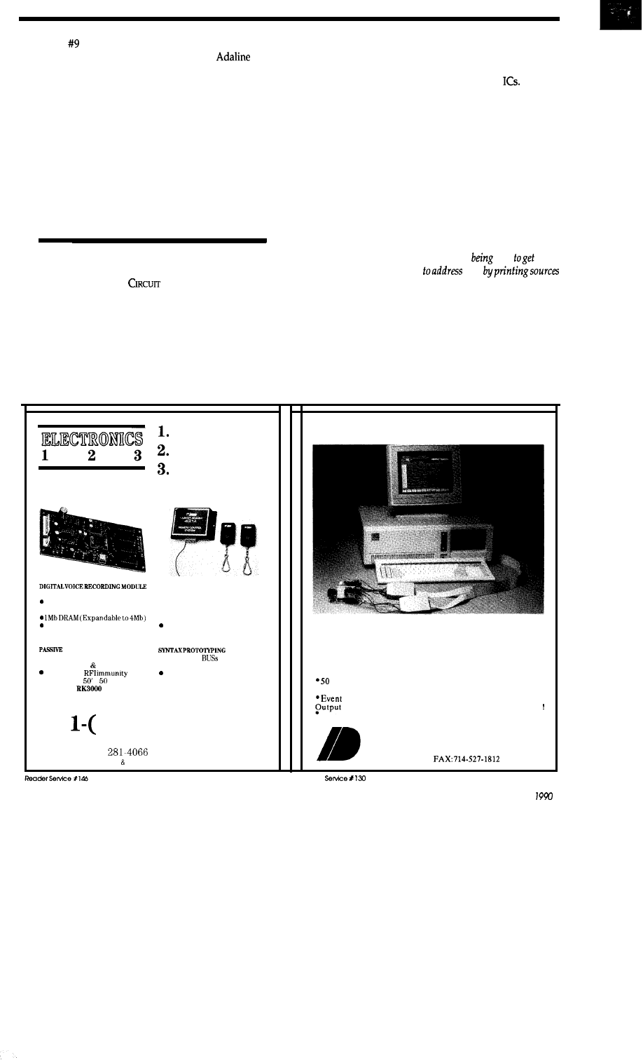
Long recording up to 2 mins
10 bit A/D, 32 Kbps
. Auto repeat feature
Applications are unlimited
MING DVM-58
$49.99
INFRARED DETECTOR
l
Security industry quality
l
Very compact reliable
SMT w/best
l
Cover area
x
ROKONET
$49.99
RF REMOTE CONTROL SYSTEM
l
4096 Digital coded
number
l
2
tiny transmitters
l
Receiver has dry contact relay
output
Confirming signal output
ZEMCO SA432
$49.99
PCB
l
All types of
l
High quality FR-4 material
Get your job done quickly
Please Call for Free Catalog
800)
669-4406
977 S. Meridian Ave., Alhambra, CA 91803
Tel: (818)
Fax: (818) 576-8748
VISA MASTER CARD ACCEPTED
PC-Based Logic Analyzers
Sophisticated Logic Analysis
a’, Unsophisticated Prices
ID160 (50 MHz) for $695
*ID161
(100 MHz)
for $895
MHz or
100
MHz
Sampling l 8K Trace Buffer
l
32-channel
Operation *Multi-Level Triggering *State Pass Counting
Timer/Counter
l
Performance Histograms
l
Hardcopy
*Disassembles popular E-bit micros *and much more
30 Day Money Back Guarantee
INNOTEC DESIGN, INC.
6910 Oslo
Circle,
Suite 207
Buena Park, CA 90621
Tel: 714-522-1469
Reader
April/May
7
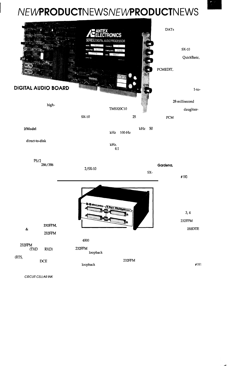
FOR PC
Systems integrators and
PC users can now add
performance digital audio
functions to their systems
and application programs
with a new board from Antex
Electronics Corporation. The
Series
SX-10 digital
audio processor features
multichannel ultra high
fidelity,
sound
sampling and reproduction
for IBM PCs and compatibles.
The unit is designed to
fit into an expansion slot of
any IBM AT,
Model 30,
or any compatible
computer and allows the user
to receive both analog and
digital audio signals from a
variety of sources including
natural voice, CDs, DAT
players, and other digital
devices. The
can
digitize two audio channels,
converting the stereo sound
into digital input that can be
stored on a hard disk or CD
ROM. Once stored, the user
can manipulate the audio
data and perform mixing
editing, and archiving tasks.
The SX-10 can record and
playback simultaneously, so
“overdubbing” using a PC
becomes a simple process.
The Series
is a
full-length board designed
around the Texas
Instruments
digital
signal processing
chip running at
MHz. Sampling rates are
software programmable, and
can range from 6.25
to
in
steps. Resolu-
tion is 16 bits, and audio
bandwidth is 20 Hz to 20
The board also allows
for
ADPCM (Adaptive
Differential Pulse Code
Modulation) data compres-
sion for decreased disk
storage requirements.
An on-board digital
input interface allows the
10 to be connected directly to
CDs,
and other digital
sources. Programmers can
achieve direct-to-disk
recording and playback by
using an optional Series 2
driver to call the
from a
high-level programming
language such as
Pascal, Turbo Pascal, and C.
An editing program,
is also available to
allow viewing and manipu-
lating up to three audio files
on-screen.
The SX-10 requires an
IBM AT or higher with a
1 interleave factor disk
controller, a hard disk with a
maximum
access time, and DOS 2.0 or
greater. A special
board is also available to
allow
digital output to
optical disk drives, DAT
machines, and other digital
recording devices.
The price of the SX-10 is
$1995.00 and the optional
daughterboard is $450.00. A
one-time fee for the software
driver is $750.
Antex Electronics Corp.
16100 South Flgueroa Street
CA 90248
(213) 532-3092
Reader Service
FOUR-PORT MULTIPLEXER
Combining the signal
and handshaking lines from
four different RS-232 cables
and sending them up to 4000
feet on a single cable is
possible with the four-port
multiplexer, Model
from B B Electronics. At
the far end, another
separates them into the four
different cables. Each port of
the
supports two
data lines
and
and four handshaking lines
CTS, DTR, and DSR)
and is wired as a
port.
A typical application would
be to connect a small cluster
of terminals and printers
located up to
feet away
from their host computer.
The
also
features a built-in
mode to test for installation
problems. It automatically
falls into the
mode
if the two-pair interconnec-
tion wiring is broken, or if the
power is off at the far end.
The interconnecting wire
should be a two-pair twisted
telephone cable for best
results.
The
can handle
baud rates up to 9600 bps
with any combination of bits,
parity, and so on. Converters
are available to change the
DCE port configuration to
DTE. These DCE-to-DTE
converters cross RS-232
connector pins 2 to
to 5,
and 20 to 6 and 8.
The Model
sells
for $149.95 including power
supply. The Model
DCE-to-DTE convertor sells
for $15.95.
B & B
Electronics
4000 Baker Road
P.O. Box 1040
Ottawa, IL 61350
(815) 434-0846
Reader Service
a
“PLUG AND RUN” PORTABLE
BACK-UP SYSTEM
A
portable hard
disk back-up
system that
operates
through the
serial
port of any
PC
has been
announced by
Analog
Digital Periph-
erals Inc.
The Easi
Tape is a self-contained,
x
x
mini-car-
tridge tape system that
emulates a large floppy disk.
No special interface cards
are required, so the unit is
truly a “plug-and-run”
device that can be moved be-
tween computers as required.
Through the use of an
included proprietary MS
DOS compatible software
driver, Easi Tape accepts
standard DOS commands,
such as COPY and XCOPY,
and can back up 32 mega-
bytes of data. Reed
ECC error checking is incor-
porated for virtually
free back-up.
The Easi Tape system
can also be used in data
logging applications to pro-
vide 32 megabytes of storage
over RS-232, GPIB-488,
422,
current
loop, or
bidirectional
parallel interfaces. The unit
can be controlled either
manually or from the host, so
it can accommodate both
“smart” and “dumb” devices.
Baud rates from 110 to
are available, and the unit can
be used for CAD/CAM
archival or active storage.
Other applications with
MSDOS-based computers
include: disk capability for
single-board computers,
downloading and uploading
part information for CNC
machines, direct reading and
writing of
formats
on 3.5-inch-based laptops,
and external storage for
hand-held PCs.
The Easi Tape system is
available with case and
power supply for $1295.00.
The system with LED display
and manual controls is
available for $1495.00, and
the system with an LCD
display and manual controls
is available for $1595.00. All
prices reflect single quanti-
ties, and multiplequantity
discounts are available.
Analog & Digital
Peripherals, Inc.
251 South Mulberry St.
P.O. Box 499
Troy, OH 45373
(513) 339-2241
Reader Service 192
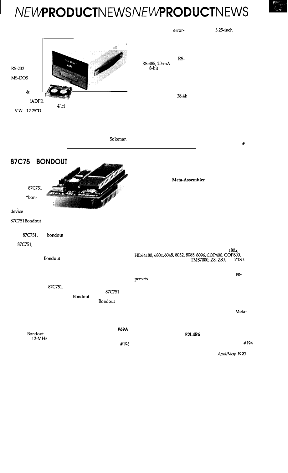
BOARD
A special
version of the
Signetics
microcontroller,
called a
dout,” has been in-
coruorated into a
1
to aid in writing and
debugging software. The
Board from
Parallax Inc. plugs into a
socket normally occupied by
a DIP
The
is functionally equivalent to
the
but its program
resides in an external EPROM
rather than in the microcon-
troller itself. The
Board accepts a 2764 or 27128
as the external EPROM.
The external EPROM
allows faster and less costly
programming and erasing
than with an actual
The external EPROM Board
can also be used with a ROM
Emulator, such as the
Parallax 2764 ROM Emulator,
to reduce normal program-
ming, testing, and erasing
cycle time from 2040
minutes to two seconds or
less.
The
Board
provides a
clock and
power-on reset. The Parallax
ROM Emulator, if used,
plugs into the board’s
EPROM socket and connects
to the parallel port of an IBM
PC or compatible. When
used with the ROM Emula-
tor, the system features com-
mand line software, which
can be run from batch files,
for automatic downloading
after assembly; a full-screen
editor for program modifica-
tion; and a tristate reset
output to restart the target
system after downloading.
The Parallax
Board is available
for $219. The
Board
and 2764 ROM Emulator may
be purchased together for
$348.
Parallax, Inc.
6200 Desimone Lane,
Citrus Heights, CA 95621
(916) 721-8217
Reader Service
UNIVERSAL CROSS-ASSEMBLER
A table-based cross-assembler that compiles programs for
many different target processors on any MS-DOS computer
has been announced by Universal Cross-Assemblers. Version
2.00 of the Cross-16
allows the user to
assemble source code from over 20 different microprocessors,
microcontrollers, and digital signal processors, using the
original manufacturer’s mnemonics. The program reads the
assembly language source file and a corresponding assembler
instruction table, and writes a list file and an absolute hexa-
decimal machine file in binary, Intel, or Motorola formats.
This hex file can then be downloaded to most EPROM pro-
grammers, EPROM emulators, and in-circuit emulators.
The two-pass (a third pass if a phase error occurs) assem-
bler supports arithmetic operators and integer constants
identical in form and precedence to the ANSI C programming
language, as well as several common assembler conventions.
Informative error messages identify the exact row and column
in which syntax errors occur, and are compatible with many
programming editors. Processor families include:
6502,
NSC800, TMS32010, TMS370,
and
The Cross-16 User’s Manual includes full directions for
writing new, and modifying the existing, processor tables.
Since many new processor instruction sets are merely
of one of the supplied processors, this can be as simple
as adding lines to an existing table. This feature prevents the
assembler from becoming obsolete. The manual also includes
an example source file for each processor on disk.
The Cross-16 will run on any system that uses MSDOS
Version 2.0 or later, at least 256K of RAM, and a 3.5” 720K or
5.25” 360K floppy disk drive. The program is not copy
protected. The suggested retail price for the Cross-16
Assembler is $99.00, including airmail shipping and handling.
Universal Cross-Assemblers
P.O. Box 6158
Saint John, N.B. Canada
(506) 847-0681
Reader Service
9
NEWPRODUCTNEWSNEVVPRODUCTNEWS
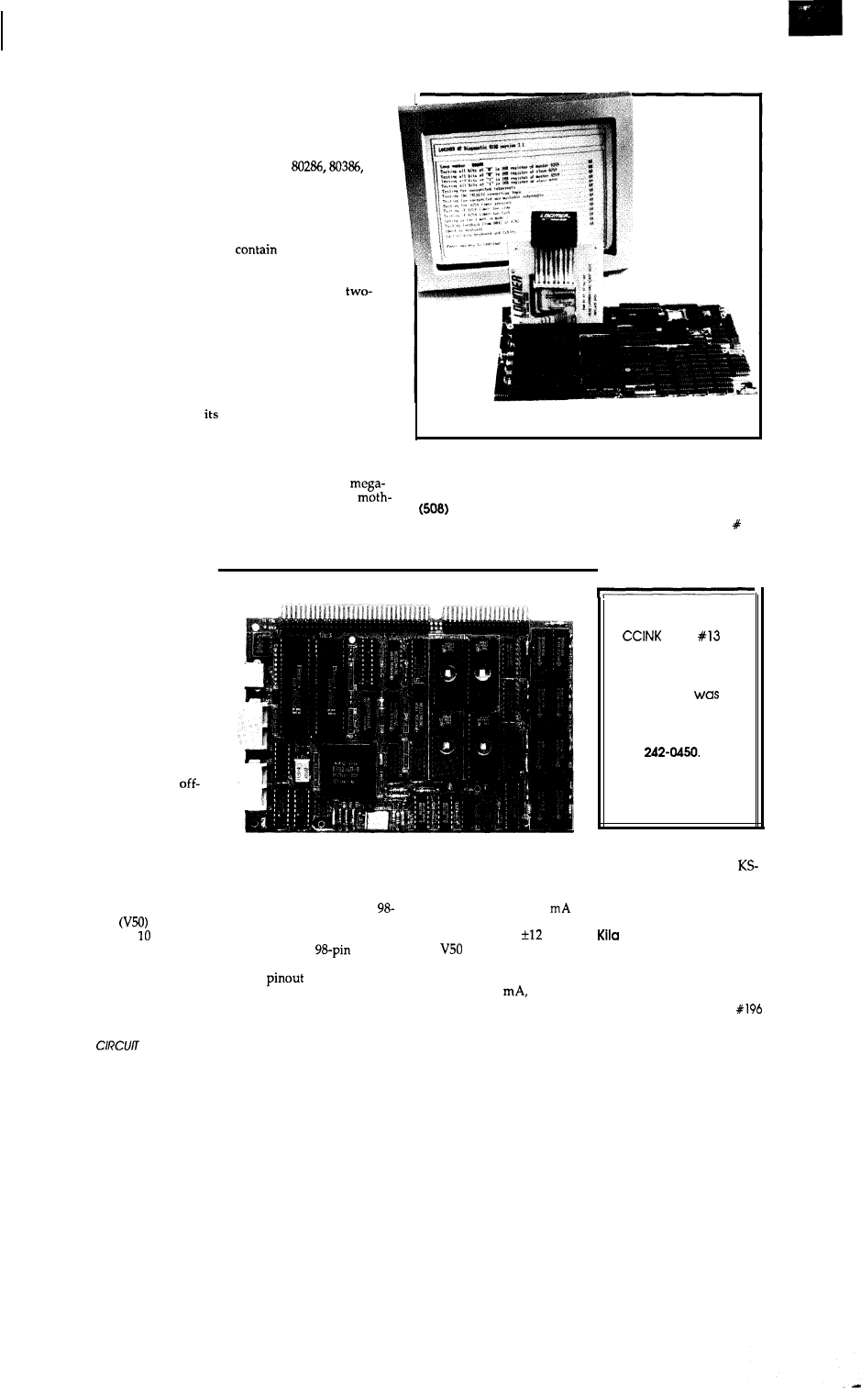
IN-CIRCUIT DIAGNOSTIC SYSTEM
FOR PC
r
A diagnostic system designed to facilitate the trou-
bleshooting and repair of IBM PC/XT, AT,
and
compatible system boards has been announced by Total
Power International Inc. The LOGIMER
system
consists of a
hardware/firmware add-on board that contains diagnostic
codes. It comes with three ROM chips and plugs into any
expansion slot. The ROM chips, which are installed in place
of the existing ROM BIOS chips,
a program that
makes more than
a
thousand tests in less than one minute,
and displays setup instructions and error messages on-screen.
In the event of a computer screen malfunction, a
digit alphanumeric display on the card will display hexadeci-
mal error codes. The user’s manual and supplementary disk-
ette provide additional diagnostic information.
LOGIMER has the capability for detecting intermittent
breakdowns. It will still initialize both displays, perform its
diagnostic tests, and relay useful information about the
system under test with many intermittent controller, timer,
and memory chips. It also can carry out loop tests to allow
testing during burn-in, and
results may be output to a
printer or screen.
The LOGIMER card can locate the exact number of a
defective chip, and shows defective RAM chips on a screen
error map to allow easy replacement. It performs complete
Total Power International, Inc.
memory diagnostics including EMS memory up to 16
418 Bridge Street
bytes, and locates up to 70% of real breakdowns on the
Lowell, MA 01850
erboard.
453-7272
The LOGIMER card is priced at
$399.00.
Reader Service 195
ROM-BASED CPU
CARD
A controller card from
Kila Systems makes diskless
stand-alone or embedded ap-
plications easy to design. The
KS-5 is a ROM-based CPU
card that is configured for an
IBM PC/AT bus. Using a
passive backplane and
the-shelf PC/AT-compatible
cards, a user can run existing
applications and MSDOS
directly from EPROM. MS
DOS takes up 83K of the
256K total ROM space,
leaving 173K available for ap-
plication programs.
The card features the
NEC 70216
CMOS CPU
running at 8 or MHz with
zero wait states. From 512K
to 1 megabyte of dynamic
RAM is available, but usable
RAM excludes the ROM
space, which can be up to
Correction:
In
Issue
“New Product News.”
the telephone number
for
Macrochip
Research Inc.
Incorrect.
The correct number is
(214)
We are sorry for any
inconvenience this may
have caused.
256K. Five RS232 serial
ports are available at pro-
grammable baud rates up to
38.4 kilobaud. The card’s
pin edge fingers are designed
for insertion into a passive
backplane. A
I/O
expansion connector with the
same
as the PC/AT
bus is available for piggyback
cards to interface printers,
floppy drives, SCSI, and key-
board.
The card is 4.5” wide and
6.9” long and draws 400
at 5 volts. An on-board
converter provides
volts.
The
also features a
power-down mode, and an
all-CMOS version, which
draws only 200
can run
off of a battery or solar cell.
The base price of the
5 is $299.00 and significant
quantity discounts are avail-
able.
Systems
655 Hawthorne Avenue
Boulder, CO 80304
(303) 444-7737
Reader Service
10
CELLAR INK
Letters to the
INK Research Staff
VISIBLE
INK
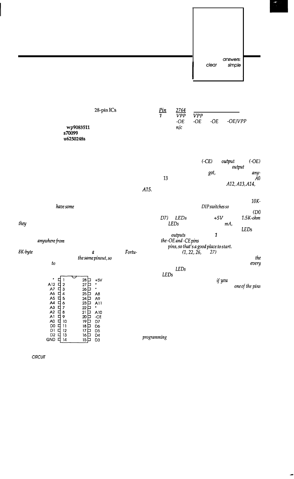
MYSTERY CHIPS
The pins marked with asterisks have thesefunctions:
Recently, I was given several
with the
following printed on them:
27128 27256 27512
V P P A l 5
i
22
26
27
AZ3
A13
Al3
-PGM -PGM Al4
Al4
They all have a UV PROM-type window on them in
addition to the writing. I would like to know if you can tell
me what they are.
I would also like to know if there is software available
for an AT-compatible 80386 computer that performs math
operations like the HP-28C calculator does.
P.L. Robertson
Suffolk, VA
Because those chips are most likely already programmed,
you can wire up a test circuit to read out the data and see what
you’vegot. The EPROMs require an address to select one of the
stored bytes, plus chip enable
and
enable
control
lines toactivate the infernal circuifyand
drivers.
Depending on which chip you’ve
you must provide
wherefrom to 16 address lines; the least-significant line is
and the most-significant one will be either
or
You obviously
house-marked EPROMs, but the
markings don’t provide any indication of the size or family.
You’ll need to do a little electrical exploring to determine how
work; there are not that many choices, so a few evenings
should suffice.
Unless you‘ve got something really weird, the EPROMs
may have
64K to 512K bits, with corresponding
type numbers from 2764 through 27512. The smaller ones are
devices, while the largest have full 64K bytes.
nafely, they
all
usemoreor less
fhereareonly
a handful of pins test.
The generic pinouf is:
Wire
up power and ground to pins 28 and 14, respectively.
The remaining inputs can come from DIP switches with
ohm pull-up resistors; wire the
that theyground
the inputs when closed.
You can monitor the outputs
through
on
connected to
through
resistors; the
will be dim with only 2
but you won’t
need to wire up driver circuits. Remember that the
are
OFF when the
present a logic or are disabled!
Both
must begrounded fogefanydafa
onfheoufpuf
Makesurefhaf
the four “odd” pins
and
are high, then vay the
other address lines to see whether you’regeffingany data on
outputs. A blank EPROM will have FF hex stored in
location, so if the
remain
off
that’s
the most likely reason.
If the
blink in interesting patterns, you‘re in luck!
Now start testing the “odd” pins to see
get different data
foreachposifion;if fheoufpufs don’t changewhen
is low, if‘s not an address line. Simple trial and error will hone
in
on the right answer fairly quickly.
Once you know the EPROM size, you can erase them and
fy programming new data. Space doesn’t let us go info the
details here, but once you
know the EPROM family there are
only a few choices for the programming method. Data sheets for
some known EPROMs (available from the usual mail-order
suppliers)
and a little head-scratching will show you that the
can
be done quite easily; you can probably wire up
a simple circuit using your ‘386 clone and a few latches!
12
CELLAR INK
and
The2764
project may
serve as inspiration; that was written up in volume
of
“Garcia’s Circuit Cellar.“ You will need
moreaddress
bits
if your EPROMs are bigger, the programming voltages may be
different, and the programming algorithms are much more
intelligent, but it’s all possible with software.
rummaged around in his pile
of
diskettes and came up with a
public-domain program that will
on the Circuit Cellar
BBS long before you
this. Dial us up and t y it out!
LONG-DISTANCE X- 10
A couple of questions about the X-10 system:
The Heath-Zenith #SL-5320 outputs an X-10 signal
when its infrared detector is activated. If the detector is at
a neighbor’s house, I want to receive the signal at my home
(neighborhood watch scheme).
How far back up the power line will communications
take place? My guess is up to the first power transformer.
Please verify that a
240-V capacitor connected
across the two “hot” lines of the usual house wiring system
will allow signals on one leg to operate equipment on the
other leg as well.
Bob Fabris
San Jose, CA
You aren’t alone in wondering just how far “up the power
line” your X-20 signals will
but you may be the first
person we’ve encountered who actually wants your neighbor to
receive your
There is no simple way to predict whether the X-20 carrier
will make it to a given point in your own home, let alone out to
thepoleand back
building. Znfact, we
X-IO outlet or switch controller mysteriously “stop working”
for a few hours, days, or weeks, then start up again as though
no thing was wrong.
The rule of thumb is that the signals will not pass through
the distribution transformer on the pole, so if your neighbor’s
house is on a different transformer you “can’t get there
here” no matter how much you want to.
ZOO
which may be a little high for houses with very low line
impedance, so you may need a
cap to punch the signal
between the circuits. any event, the capacitor voltage rating
should be two or three times the expected line voltage, so a
or
AC capacitor is the minimum you should use. A
volt capacitor
give you much leeway when the power
company jacks up the voltage by percent!
you build such a unit, you should include a small safety
fuse and mount the unit in a grounded or well-isolated box.
Unlikemostprojects, thisonemaykill you
aren‘t careful about the details.
LASERS
HELIUM NEON KITS
consist of a He Ne Head and matching Power Supply. FDA approved.
l
1
Kit with 12 VDC Power Supply $110.00 with 110 VAC Power Supply $135.00
l
Kit with 12 VDC Power Supply
with 110 VAC Power Supply $220.00
HELIUM NEON TUBES HEADS
Hard Seat units,
l
Tubes $35.00
l
3
Tubes $75.00
l
Heads $50.00
l
1
Tubes $50.00
l
5
Tubes $100.00
l
5-7
Heads $125.00
HELIUM NEON LASER POWER SUPPLIES
High Voltage Switch-mode Regulated Factory made units
l
9 VDC input micro supply for 1
units only,
$75.00
l
12 VDC input adjustable output supply for l-7
units $75.00
l
VAC input adjustable output supply for
units $95.00
LASER DIODES DRIVERS
l
New
visible 670 nm, 3
diodes $100.00 New L.D. Drivers $35.00
l
New
800 nm, 3
diodes $50.00 Adjustable
$25.00
LASER ACCESSORIES-optics, Holography
Kits, Scanners,
Light Show Equipment, Books, Hardware and more.
FREE CATALOG-call
or
write today for
our latest catalog or to place a C.O.D. order.
April/May
13
A FEW WORDS FROM THE STAFF
ingan
American dining room suite, or preparing
a
to
run the Baha 1000, when you progress
“foolingaround” to
Dear Readers:
serious, professional-quality projects you have to have the right
We get
a lot of letters this:
tools for the job.
Admittedly,
scope will set you backabout a kilobuck,
I’m having trouble getting my project running and
but that’s the cost of
to the game. We don’t want to
need your help. I am
a 32-bit microprocessor with 45
discourageyoufrom experimenting with electronics, but
interrupt sources, an ADC and DAC updated by
don’t want to encourage you to waste your time tying to do
driven firmware, and DMA circuitry for my
something that simply can’t be done.
signed hard disk controller. My tools include a soldering
iron, diagonal pliers, and a continuity checker, but I do not
have an oscilloscope or a logic probe.
In Visible INK, the Circuit Cellar Research Staff answers
folks, we are not magicians here! Just as you
microcomputing questions from
readership. The
wouldn’t attempt to
play pro football without a helmet and full
representative questions are published each month
as space permits.
pads, you shouldn’t expect to debug high-speed digital electron-
ics without
tools.
For example, if that microprocessor doesn’t start up, you’re
going to have to verify that the clock is running, that the control
signals arefunctional, that the bootstrap EPROM is delivering
the right data, and so forth. You don‘t need a $20,000 logic
analyzer
that, you will
.a
logic probe won’t cut the mustard.
Send your inquires to:
INK Research Staff
c/o Circuit Cellar INK
Box 772
Vernon, CT 06066
Ail letters and photos become the property of
and cannot returned.
Understand, there’s quite a lot of electronic experimenta-
tion you can do with
y
Above
a
certain level of
complexity, however, you simply have to make the commitment
201 Very Useful
to
obtaining theproper tools. This fact is not unique to
202 Moderately Useful
Whether you’re
designing a single-board controller,
203 Not Useful
WEATHER STATION
USED BY RADIO AND TV METEOROLOGISTS.
NOW ONLY $285
We’ve sold
Digitar
Weather Master weather stations to radio and
TV stations from Bangor, Maine to central Borneo because we
offer sophisticated, professional-quality weather monitoring at
an incredibly low price. Our state-of-the-art microcomputer
technology gives you unprecedented ability to monitor, record
and compute weather data.
Weather Master
a
computer, electronic barometer, remote precision wind direction
vane, wind speed sensor, external temperature sensor, pro-
grammable alarms, mounting hardware and 40’ of cable all
for
only
$2851
Features include:
(w/memory)
Record
Altimeter (w/alarm)
l
Wind Speed
Rain’
l
Wind
Time of Day
l
Windchill Factor
Elapsed Time
Four-Year Calendar
Temp.
. Metric
and Standard
Outside
Temp.
Programmable
Temp. Record
l
LCD
WEATHER MASTER WEATHER STATION ONLY
ORDER TODAY:
MONEY
I-YEAR
Self-emptying rain
Add
CA residents add sales tax.
F
AX
l
VISA
l
3465 DIABLO AVE. . HAYWARD, CA 94545
STOMP OUT
EPROM
. . . . . .
The PROM KING emulates EPROMS saving
both time and money during your
cycle. Programmable in seconds via your PC
printer port or any computer RS232 port, it can I
emulate most
devices.
bit devices
8-256 bit downloads
High speed download:
Easily expandable:
-Universal RS232
-4 EPROMS per unit
-PC printer port
-Up to 8 units
Menu driven software
Also programs like
Battery backup
a real EPROM
$599 for 150nS units with
bits
Ask for pricing of other options
Made in USA by:
Box 239
NY
516-737-5147
14
CIRCUIT CELLAR INK
Build A Simple
SCSI-to-Anything Interface
Take Advantage of the
to
Your Designs
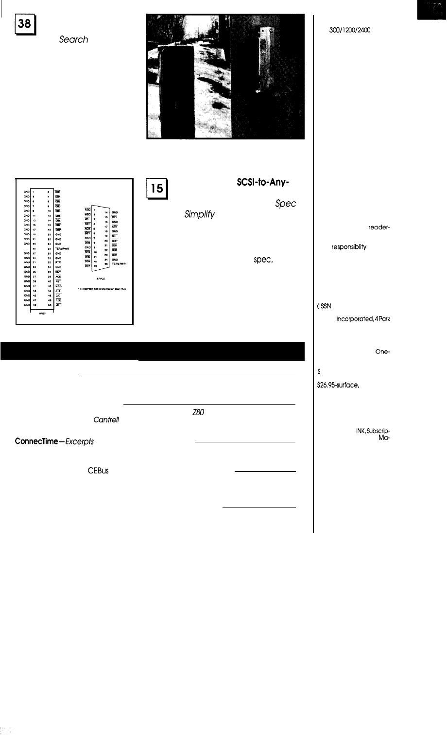
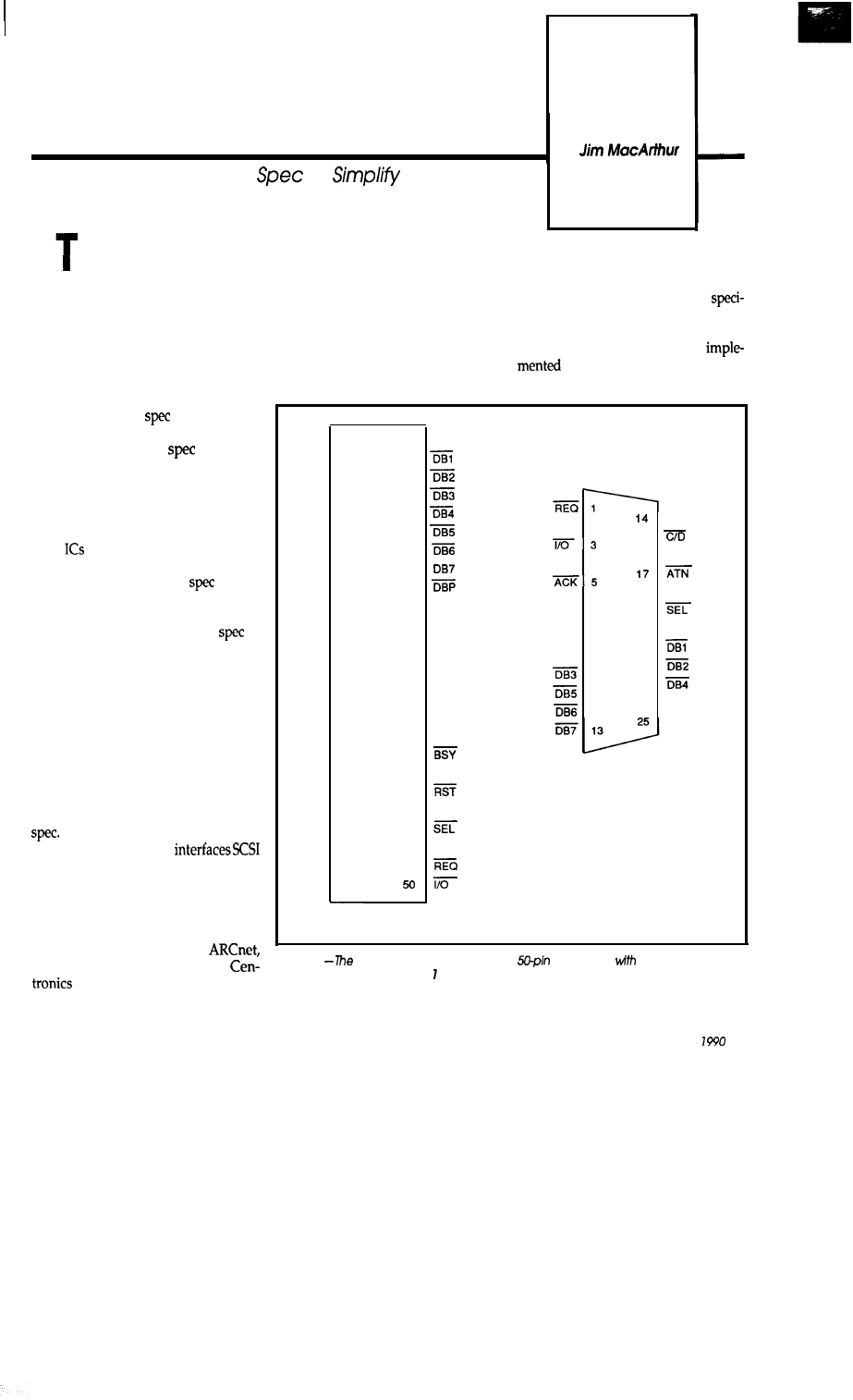
he SCSI (Small Computer
System Interface) bus, as envisioned
by the ANSI committee, is a parallel
bus intended to connect small com-
puters to intelligent peripherals. Be-
cause of SCSI’s high degree of “polite-
ness” (error recovery procedures,
message passing, etc.), it is impossible
to design a peripheral which fully im-
plements the SCSI
without some
kind of microcontroller. This fact, plus
the complexity of the
itself, has
kept hackers from taking full advan-
tage of the bus.
driver to interface a Macintosh to the 50 lines. It is typically implemented as
circuit.
a 50-conductor flat ribbon cable, or as
25 twisted pairs. The maximum
THE SCSI INTERFACE
fied length is six meters. In the mis-
guided interest of saving space, Apple
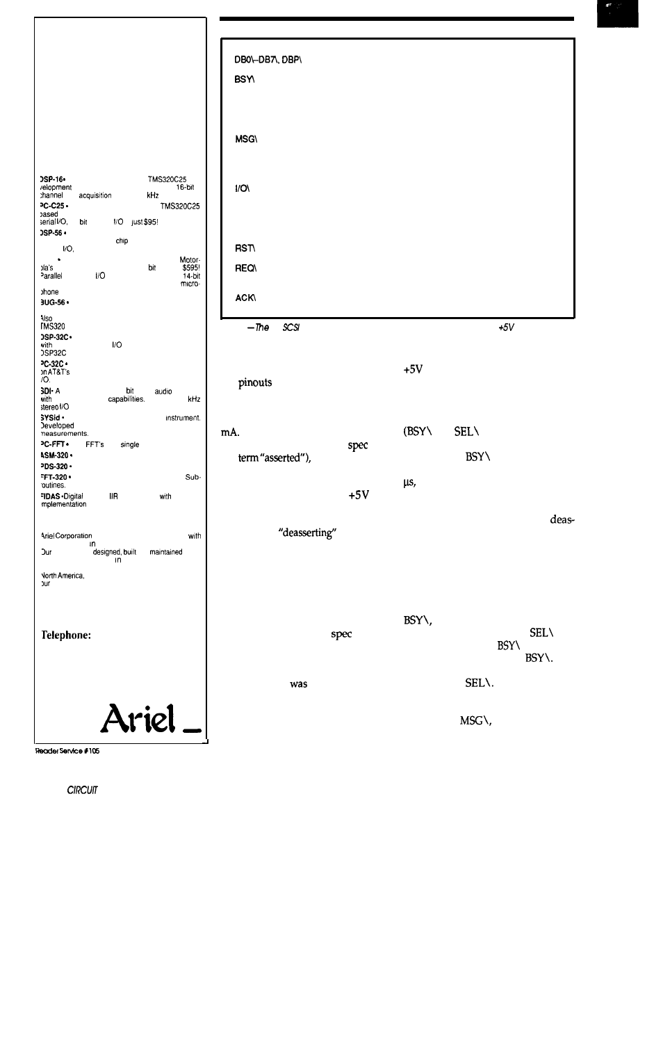
SCSI is an 8-bit parallel bus with removed 25 ground lines and
18 signal lines, one termination power
the SCSI interface as a DB-25
line, and 31 ground lines, for a total of connector, thereby restricting the
However, it is possible to design a
circuit which can interface SCSI to
virtually anything, using as few as
eight (buffers and gates only) and
no microcontroller. The trick is to
implement enough of the
so that
the circuit doesn’t interfere with “le-
gitimate” SCSI devices, while fla-
grantly violating the rest of the
in
the name of hardware simplicity.
Of course, there is a tradeoff: It is
necessary to write a special SCSI driver
for thecomputer tocommunicate with
the interface circuit. Because the cir-
cuit uses a very simple protocol,
however, writing the driver is far less
difficult than writing SCSI firmware
for an intelligent peripheral.
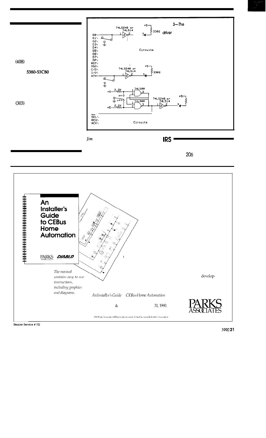
GND
1
G N D 3
G N D 5
G N D 7
G N D 9
GND 11
GND 13
GND 15
GND 17
GND 19
GND 21
GND 23
25
GND 27
GND 29
GND 31
GND 33
GND 35
GND 37
GND 39
GND 41
GND 43
G N D 4 5
GND 47
GND 49
2
DBO
4
6
8
10
12
14
16
18
20
GND
22
GND
24
GND
26
TERMPWR
28
GND
30
GND
32
ATN
34
GND
36
38
ACK
40
42
MSG
44
46
C/D
48
MSG 2
15
RST 4
16
18
BSY 6
19
G N D 7
20
DBO 8
21
G N D 9
1 0
22
1 1
23
1 2
24
GND
GND
GND
DBP
GND
TERMPWR
APPLE
The first part of the article will
give a quick overview of the SCSI
Then follows
a
description of the
basic hardware, which
to a generic 8-bit data-address bus.
From this circuit, one can design an
interface to virtually any parallel bus
or controller IC. Possibilities include
interfaces to the PC bus, STD bus,
Metrabus, CAMAC, A-bus,
A/D converters, GPIB, RS-232,
ports, and so on. The remain-
der of the article will present a simple
l
TERMPWR not connected on Mac Plus
ANSI
Figure 1
SCSI specification
calls for a
connector
18
signal lines. one
termination
power line, and3 groundlines. In designing the Macintosh, Apple removed
25 ground lines,
saving space in the connector, but limiting the maximum length for a
reliable cable.
April/May
15
FOR THE IBM PC
Digital
Signal
Processing
DSP Development Tools and
Standalone Systems from Ariel
From the IBM PC:
A complete TMS32020 or
De-
System on a single board, with
2
data
of up to 50
per channel.
The lowest cost full speed
card available. Just $595 with parallel and
14
analog
IS
Integer DSP development system based on
he Motorola 56000 DSP
with two channel 16 bit
analog
compatible with Ariel’s Bug-56.
K-56 A new, low-cost DSP card based on
fast DSP56001. Full speed 24 DSP for
and serial
standard. Available with
analog ND, NeXT compatible DSP port and
preamp.
Fast, efficient symbolic debugger for the
‘C-56 and DSP-56. Macros, windows, the works.
available: Assembler/Simulator, C Compiler and
Code Converter.
Floating Point DSP development system
true 16 bit analog
based on AT&T’s 32 bit
chip.
Low cost floating point coprocessor based
DSP-32C standard with parallel and senal
complete, 2 track 16
digital
recorder
advanced editing
Real-time 50
using any PC.
Comprehensive acoustic test
by Bell Labs for quick and accurate
Fast
on a
card.
The fastest TMS320 Assembler.
Deluxe TMS320 Program Development.
256 and 1024 point TMS320 FFT
Real-time demo program too.
FIR and
Filter Design
real time
on the DSP-16.
For You:
is dedicated to providing you
he best values high performance DSP products.
products are
and
in the
J.S. The best support the industry
IS
always at
land. Ariel’s products are sold directly throughout
and are available worldwide, through
international dealer network.
4riel Corporation
133 River Road
Highland Park, NJ 08904
201-249-2900
Fax: 201-249-2123
Telex: 4997279 ARIEL
DSP BBS: 201-249-2124
16
CELLAR INK
8 data
lines
plus odd parity.
Busy, asserted by initiator or target to gain control of the
bus. Whoever is asserting BSY owns the bus.
SEL\
Select, asserted by initiator to establish communication
with
a
target.
CID\
Message, asserted by target to indicate message phase.
Command/Data, asserted by target to indicate command
phase.
In/Out, asserted by target to indicate data direction is
toward initiator.
ATN\
Attention, asserted by initiator as a request to send a
message to the target.
Reset, asserted by initiator to reset the bus.
Request, asserted by target to start transfer of one byte
of data.
Acknowledge, asserted by initiator to complete transfer of
one byte of data.
Table 1
18
signals. A nineteenth signal. TERMPWR, supplies
to the pull-up
resistors in the terminators.
maximum length for reliable opera-
tion to six feet or so. The differences in
the
for the two implementa-
tions are shown in Figure 1.
Signals are driven by open-collec-
tor drivers that must be able to sink 48
All signals are active low. When
not being driven (the SCSI
uses
the
signalsarepulled
high by terminators at both ends of
the bus. The terminators consist of a
220-ohm resistor to
(or
TERMPWR) and a 330-ohm resistor to
ground for each signal. In addition to
their role of
signals, the
terminators reduce ringing on the bus
by absorbing signals that reach the
end of the cable, rather than reflecting
them.
SCSI allows up to eight devices to
be physically attached to the bus. Each
device is assigned a unique bus ID
from 0 to 7. The SCSI
divides
devicesintoinitiatorsand targets. With
few exceptions, host computers are
initiators and peripherals are targets.
Although SCSI
carefully designed
to allow multiple initiators, the vast
majority have only
one.
Therefore, our
first simplifying assumption is that
there is only one initiator on the bus.
The 18 SCSI signals are shown in
Table 1. A nineteenth “signal” is
TERMPWR, which is connected to the
supply (through a rectifier1 of
each device on the bus. It supplies
power to the pull-up resistors in the
terminators.
Starting from a Bus Free phase
and
deasserted), an ini-
tiator arbitrates for control of the bus
by asserting
and the data bus
line corresponding to its ID. After 2.2
the initiator inspects the data bus.
If no data lines higher than its own are
asserted, it gains control of the bus by
asserting SEL\. Otherwise, it
serts BSY\ and waits for the next Bus
Free phase.
Once on the bus, the initiator
chooses which device it wishes to
communicate with by asserting the
data bus with the logical OR of its ID
and that of the target. It then deasserts
thus entering the Selection
phase. When a target sees
and
its ID\ asserted and
deasserted,
it responds by asserting
The
initiator completes the selection by
deasserting
The target now
owns the bus.
The target then manipulates the
phase lines
C/D\, and I/O\
to send and receive data, commands,
and messages to and from the initia-
tor. When the command is finished,
the target gets off the bus by
serting BSY\. We won’t get into ex-
actly what the target does once it has
the bus, because that’s the part of the
we’re going to ignore.
THE HARDWARE
Now let’s look at the problems of
designing a device that only partially
conforms to the SCSI
The first
problem is that we want our interface
to be invisible to the initiator when it
is running its normal SCSI drivers.
This is important because the host
computer often initializes the bus by
selecting every device ID to see what’s
out there. If it selects a device that
requires a special driver, the initiator
will probably hang. Our solution is to
modify the selection protocol so that
our interface will respond to selection
only if the initiator asserts SEL\ and
the target’s ID, but not the initiator’s
ID. In order to simplify the hardware,
we assume that the bus has only one
initiator, and that it is located at ID 7.
Once our target has gained con-
trol of the bus by asserting BSY\, we
are free to play with the SCSI signals
any way we want, with the following
exceptions: BSY\ must remain as-
serted, and SEL\ and RST\ must
remain deasserted. As long as these
rules are followed, there is nothing
the initiator or target can do on the bus
that will affect the other targets. That
gives us a pretty free rein with the re-
maining six control signals.
Before we go hog-wild,
we
should
consider any constraints imposed by
the initiator’s hardware. On
the
tosh, and in many other small com-
puters, the SCSI interface is handled
by a single-chip SCSI controller, the
NCR 5380. While it can assert all six
control lines, it can’t assert them all at
the same time. When configured as an
initiator, it can only assert ATN\ and
When configured as a target, it
can only assert MSG\, C/D\, I/O\,
and
Because target mode gives
us twice as many lines to play with,
we will reconfigure the initiator as a
target when talking to our interface.
The 5380 uses the I/O\ line to
control the direction of its transceiv-
ers, so I/O\ is forced into service as a
write/read line. The initiator is pre-
tending to be a target, so “in” now
means towards our interface. Assert-
ing I/O\, therefore, indicates a com-
mand which writes to the interface.
The phase lines
and C/D\ are
natural candidates for the addresses,
and
is used as the strobe line.
This leaves
free as an
driven interrupt line.
can be
used asaninterface-drivendata ready
or wait line.
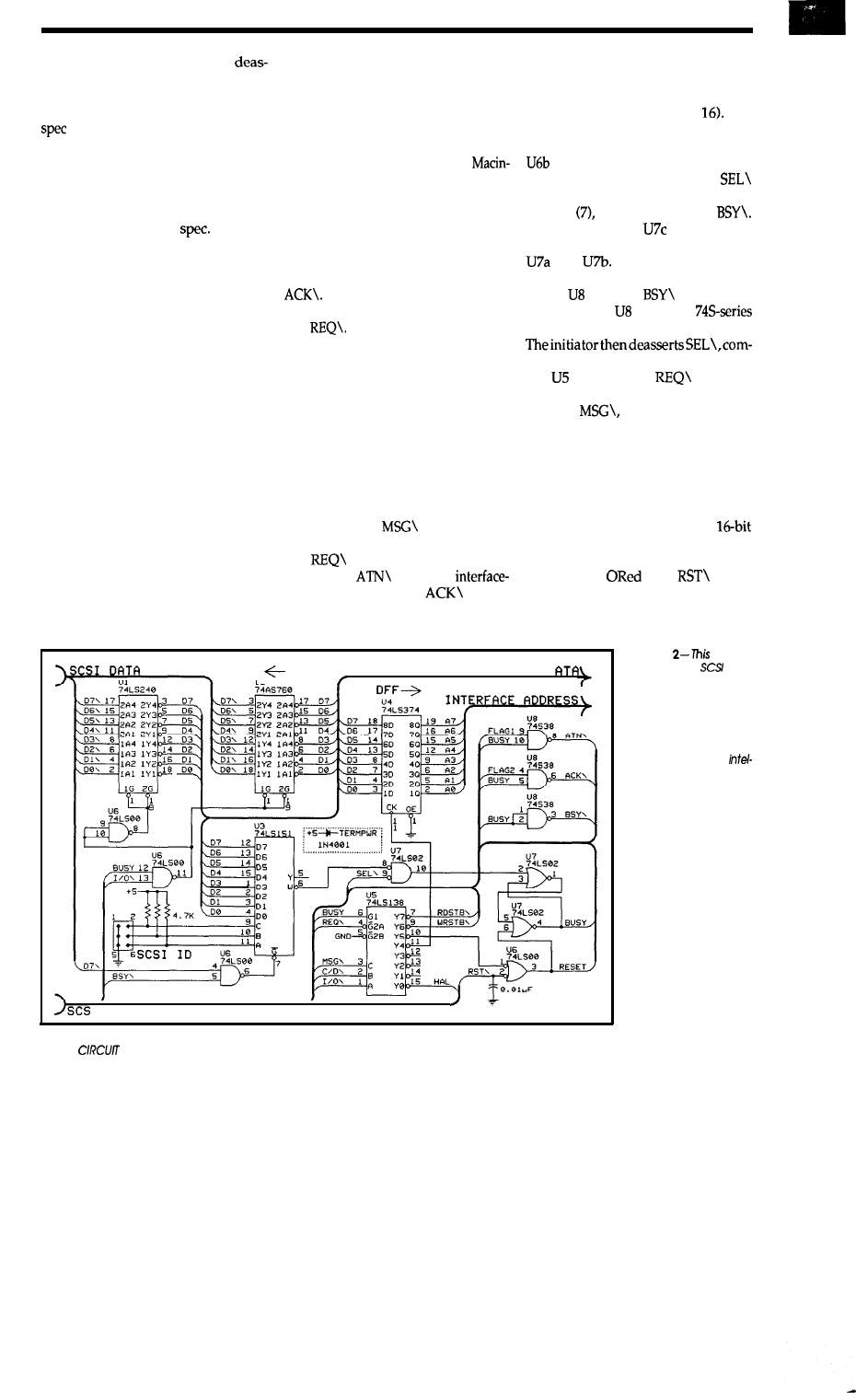
INTFRFACE D
“2
Figure 2 illustrates these tech-
niques with an interface to a generic
bus with eight data lines and eight ad-
dress lines (expandable to
The
selection process is implemented by
one-of-eight selector U3, along with
and U7. When the initiator wants
to select the interface, it asserts
along with the interface ID, but
not
its
own ID and then deasserts
When this occurs,
will go high,
setting the S-R flip-flop formed by
and
This sets BUSY high,
which causes open-collector NAND
buffer to assert
on the SCSI
bus. Note that must be a
part in order to properly drive the bus.
pleting the selection.
decodes the
line into
eight strobe signals according to the
states of
C/D\, and I/O\. All
of the even-numbered strobes (I/O\
asserted low) are writes, and all of the
odd strobes are reads. Strobes 7 and 6
are the primary read and write strobes.
Strobe 4 writes the address into octal
flip-flop U4. Strobes 3 and 2 can be
used as high-byte strobes in
systems. Strobe 0 can be used to latch
eight additional address lines.
Strobe 5
with
resets
the BUSY flip-flop, removing the in-
terface from the SCSI bus. The capaci-
tor on the RST\ line prevents glitches
Figure
circuit
Interfaces
to a
generic bus with eight
data lines and eight
address lines (expand-
able to 16). The design
trades simple hard-
ware and custom soft-
ware for the more
ligent hardware and
‘standard’ software of
traditional SCSI.
I CONTROL
18
CELLAR INK
The following defines are the addresses of the internal registers
of the NCR 5380 SCSI controller in the Mac Plus, SE, and II.
#define
SCSIBase68000 0x580000
#define
SCSIBase68020
#define
0x00
#define
0x01
#define
#define
0x11
#define
0x20
#define
0x21
#define
0x30
#define
0x31
#define
0x40
#define
0x50
selects the target specified by
this routine is called, you must: not perform any "normal"
;SCSI operations until you call scuzzy-deselect.
;On entry,
contains expanded target ID, e.g., if ID = 2,
= 00000100.
contains base address of 5380.
;On return,
DO contains error
code:
0 =
no error,
1 = SCSI bus occupied, 2 = target not responding
scuzzy select:
bus phase to free.
move.b
,
target mode.
should be free, BSY off
if bus free
else is on bus, set
bra
@restore_scsi
error code
1 and return.
will reselect, bus is all ours.
move.
b
;Set bus phase to free.
move.b
data bus.
move. b
target ID on bus.
move.
b
SEL
up DO as timeout counter
select lp:
for BSY asserted
bne
@selected
if it is
dbra
;If not, loop up to 10 times
timeout:
;If timed out,
set error code
to target not responding.
bra
@restore_scsi
selected:
move.b
SEL, data
bus
rts
Target on
bus
write-address updates the
interface address
register
with the 8-bit address passed in DO.
;On entry,
contains base address of 5380.
write address:
b
C/D on, MSG
off
m o v e . b
10x1,
d a t a b u s
out to scsi bus
move.b
#OxB, WrTargCmd
REQ
;Deassert REQ
move.b
;Deassert data bus
rts
*Subroutine
write-data writes the El-bit data in
DO to the
; interface.
entry,
contains base address of 5380
write data:
b
on, C/D MSG off
move.b
data bus
move.b
out to scsi bus
listing 1
five assembly routines shown here are the special drivers required to com-
pensate for the simple hardware of this interface.
written for the
in the Apple
Macintosh, the software should be easily transported to any system using a
for the
SCSI interface.
PC
Data Acquisition
and Control Cards
paying a small fortune for
PC data acquisition and control
interfaces!
AD1000 $295
Real
Time Devices, Inc. designs and manufactures
lowest cost
interface cards
for the
bus. Our commitment is to offer
Interfaces not cheap
imports. All
cards are
backed by a one year warranty, 30 day NO
return
policy, and free technical support!
hold; three
timer/counter; 24
digital
VO
lines.
$295
AD200 4 channel
125
three
resistor
configurable
gains;
24 digital
VO
lines.
$259
AD500 8
integrating
gain
10, 100.
Extremely stable
accurate.
$239
Single channel, differential input,
integrating
B-bit D/A output; gains of
10, 100.
Plus
10 digital
VO lines.
$215
25
S-bit
D/A, 24
digital
VO
lines.
$239
DA600
Fast
in-
ternal
double buffering.
line
compatible
digital
VO
cards; 10 MHz.
Optional
buffers and pull-ups.
$951274
TC24 Five 5 MHz timer/counters; uses power-
ful AM9513 chip. Also 24 digital lines.
$218
FREE
CATALOG
today for your copy of the latest
catalog and price list for
line of
PC
bus data acquisition, control,
ex-
tender cards, technical books and accessories!
Custom/OEM designs on request!
Real Time Devices, Inc.
State College,
PA 16664
April/May 1990
19
REQ
move.b
move.b
data bus
rts
read data reads the B-bit
the intexface
to DO.
:On entry,
contains base address of 5380
read data:
C/D, MSG
REQ
move.b
DO
in from scsi bus
move.b
REQ
rts
scuzzy-deselect removes the interface from the
scsi bus,
and returns the bus to normal operation.
entry,
contains base address of 5380
return,
DO contains error code:
0 = no error, 3 = target stuck on bus.
deselect:
return error to 0
move.b
MSG off, C/D on
move.b
move.b
BSY
ne to
get off the bus
nop
btst.b
;BSY still asserted?
@restore scsi
-----
if it is not
stuck on bus
restore scsi:
move.b
5380 registers
move.b
rts
. . . .
on
(the bane of SCSI) from reset-
ting the interface. To avoid bogging
down RST\, do not use a higher value
than 0.01
If a power-on reset signal
is available, it should also be
with
and Strobe 5, so that the
interface doesn’t crash the SCSI bus
when it is turned on.
I/O\, gated with
BUSY, controls
the bus direction by enabling and dis-
abling
and U2. The
is a
good choice for bus receiver because
of its hysteresis (note that the
doesn’t have hysteresis.) As for driv-
ers, keep in mind that you need to sink
48
and that either open-collector
or tristate drivers may be used. If you
can’t find any
try
buffer
through the remaining
gate of U7, and use it as an address
line.
This
comes
in handy, for example,
when interfacing to a 12-bit ADC with
an 8-bit data bus and an address input
line. By sending
to that address
input, one can extract both bytes from
the ADC by simply doing two data
reads, one with MSG\ high, and one
with
low, which is faster than
updating the address latch with each
read.
THE SOFTWARE
Two application-specific user
flags are available to serve as inter-
rupt or ready lines.
and
gate
the flags with BUSY, and drive
and
on the SCSI bus.
One possible modification to this
circuit would be to pull U5 pin 3 high,
As mentioned earlier, this
crouslysimplehardwaredesigncomes
at the expense of having to write a
special driver to interface to it.
ever,even thisisn’tasbadasit sounds.
Listing 1 shows the five assembly
languageroutines:
write
a d d r e s s , w r i t e d a t a ,
r e a d
The subroutines were
for the
Macintosh, but it should be easy to
port them over to other machines
which use a 5380 for the SCSI inter-
face.
In order to keep things simple, we
will make one more assumption about
the SCSI bus: targets are not allowed
to disconnect from the bus until they
have completed their commands. This
means that when the bus is free, the
only device that will be arbitrating for
it is the initiator, so arbitration is
unnecessary. This saves a few lines of
code in
scuzzy select
and speeds
up access to the
The current
Macintosh SCSI driver does not sup-
port disconnection, so this shouldn’t
present a problem for most users. If it
does, the user must add arbitration
code before selecting the interface. The
other subroutines can stay the same.
The drivers do not support the
two application-specific flags. The
flags
monitored by reading the
5380’s Bus and Status Register
ACK\ is bit 0 and ATN\
is asserted.
SCSI TEST BOX
The easiest way to test SCSI hard-
ware and software is with a SCSI test
box, such as the one shown in Figure
3. This is simply a collection of
bounced switches and
but you
will be amazed at how handy it will
be. It can be used to test both the inter-
face hardware and the driver soft-
ware, and with a bit of practice, you
will find yourself whizzing through
SCSI commands in a matter of sec-
onds. A word of advice: don’t skimp
on the switches. Use high-quality
toggle or rocker switches, or your fin-
gers will wear out after the first dozen
commands.
I hope that this article has helped
to strip away some of the mystery
surrounding SCSI. It is my fond wish
that experimenters will soon be sub-
jecting SCSI to the same kind of abuse
they’ve heaped on the IBM
port. Once you’ve mastered the art of
scuzzy interfacing, you will never
again think of the Macintosh
as
a
closed
architecture.
REFERENCES
Inside Macintosh Volume IV
Apple Computer, Inc.
20525 Mariani Avenue
Cupertino, CA 95014
996-1010
NCR
SCSI Inter-
face Chip Design Manual
NCR Microelectronics Division
1635 Aeroplaza Drive
Logic Product Marketing
Colorado Springs, CO 80916
596-5612
Small Computer System
Interface (SCSI), ANSI
X3.131-1986
American National Standards
Institute
1430 Broadway
New York, NY 10018
Figure
SCSI
Test Box can be used
to
test
both
interface hardware and
software.
High-qualityswitches will
save wear and tear on the user’s fingers!
1 4 I d e n t i c a l
330Q
4 I d e n t i c a l
“Squint” MacArthur is a data acquisition
engineer at Acoustic Technology, Boston,
204 Very Useful
Mass. His nonprofessional interests include
all forms of musical expression except indoor
205 Moderately Useful
Not Useful
bagpipe music.
Hands-on info for CEBus automation.
Emphasizes the new CEBus’” standard!
This manual provides detailed instruction on the backbone
wiring that will interconnect the electronic home of the 90s
For installers of all types, and for all
applications.
Emphasizes CEBus and its application for security,
entertainment, lighting, telecommunications, and
energy management. Designed for on-site use, with
clear, easy-to-use instructions, including graphics and
diagrams. Written by Diablo Research, it reveals “insider”
information on how to wire for current and future automa-
tion products and services.
Includes a free update.
To be released in late 3Q 1990, a free update will include the last
minute changes to the CEBus standard and other new
ments. If necessary, a later update will be provided.
Order for a special price of $99 through March 1990.
to
(delivery
April 1990) is available for the prerelease price of $99,
plus shipping handling until March
To order,
call Parks Associates at (214) 369-5581, fax (214) 369-5582.
April/May
Computer-Generated
Holographic Images
Using a PC to Generate Affordable Holograms
[Editor’s Note: This article is a
practical tutorialonmethods togeneratea
hologram using an
MS-DOS computer
with a VGA screen, a 35mm camera, and
a
laser
the
hologram).
Dale Nassar has written a large
manuscript covering laser basics, light
theo y, and the fundamentals of general
holography. This article, while a practical
tutorial, is an excerpt from the larger
work.
If you would like to purchase Dale’s
complete work, send $7.50 to: Computers
and Holography, 4 Park St., Vernon, CT
06066.1
H
olographyisaphotographic
process which, unlike ordinary pho-
tography, does not record an image of
the scene photographed, but encodes
the emanating light rays themselves.
The resulting optical record is called a
hologram and can instantly recon-
struct the recorded light rays. Holo-
grams
an
illusion of the origi-
nal scene in three-dimensional space
that is remarkably life-like.
The beautiful images created by
this unique recording process are
made possible by the coherent light of
the laser. However, because a holo-
gram can be considered an array of
many bits of information, I decided to
investigate the practicality of compu-
terized hologram synthesis. In this
article I will demonstrate, without
complex analysis, how holographic
synthesis can be accomplished in the
computer room with no special opti-
cal materials or holographic lab. The
laser’s role in conventional hologram
formation is completely emulated by
22
and in some very crucial
situations the computer outperforms
the laser.
The synthesizing method I use is
straightforward and is designed to
be easily understood and inexpen-
sively applied with standard photo-
graphic and computer equipment. On
a more advanced level, a parallel
processing environment also lends
itself to the application as the holo-
graphic bits are mutually independ-
THE SINUSOIDAL GRATING
A thorough understanding
of the
process of optical interference can
easily be had by assuming light to be
made up of sinusoidal waves of en-
ergy (hence the expression “light
waves”). Figure 1 illustrates a sinu-
soidal waveform and the key ele-
ments of its structure as defined in
physical optics.
It is important to be aware of the
fact that light waves are traveling
waves; that is, the contour of the
waveform of Figure 1 should be con-
sidered
toward the right at
the speed of light. To get a mental
picture of what this means, consider
a particle on the time axis in Figure
that is allowed to move only verti-
cally in response to the amplitude of
the passing light wave. Then the
effect the wave has on the particle is
a very rapid sinusoidal vertical mo-
tion (vibration) about a fixed point on
the horizontal axis. It is obvious that
the frequency of a light wave is ex-
tremely high, visible light has a fre-
quency of the order of
Hz (100,000
FEATURE
ARTICLE
Dale Nassar
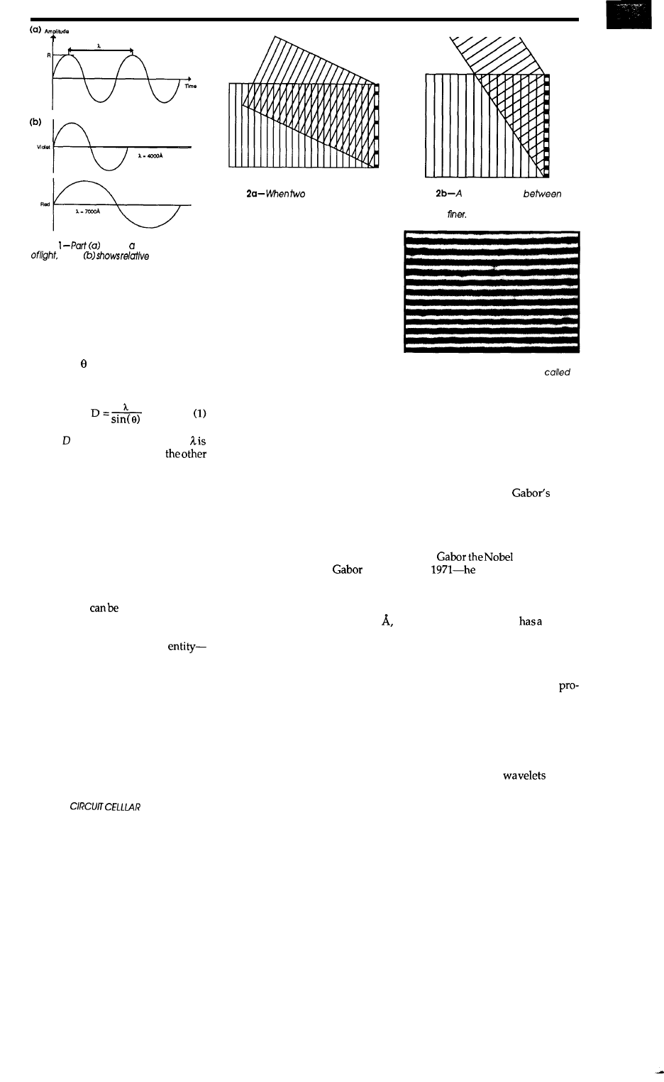
These important quantities arc
related by the very simple (and obvi-
ous) expression
where is the
frequency in Hz, c is the velocity of the
wave in m/s (3 x
for light) and
is the wavelength in meters. The
period of the wave, is the reciprocal
of the frequency. represents the
time required for one wavelength to
pass a given point. Mathematically,
the energy of a wave is a measure of i ts
intensity, which is proportional to the
square of itsamplitude. Thisencrgy is
what does the work responsible for
exposing photosensitive film.
When two plane waves
at
the surface of a film, as shown in a
cross-sectional view in Figure
interference
pattern
recorded
consists
of a series of parallel line fringes (in
the diagram the lines are
lar to the page). This is called a photo-
graphic grating and appears as in
Photo 1. Figure 2b depicts the same
situation but with a larger angle be-
tween theinterferingbeams. As illus-
trated, the
effect of increasing the angle
between the two beams causes the
fringe spacing to become finer.
3
theamplitude transmis-
sion across the surface of the grating
of Photo 1.
There are no abrupt
changes in the transmission-the
variation is sinusoidal with the fre-
quency of the waveform
the spatial frequency of the grating.
In Fourier analysis it is shown
that a wave with very sharply chang-
ing shape such as a square wave can
be
broken
down
into many sinusoidal
components, while a sinusoidal wave
is the
purest formpossible. In the case
of the abruptly changing amplitude
transmission of the grating, the result
Figure
shows basic waveform
while
wavelengths
of the extremes of the visible spectrum.
is
many
orders of diffracted beams.
Each diffraction order consists of two
beamsdeflected at equal angles meas-
ured above and below the zero-order
(straight through) beam. The angle of
deflection of the diffracted beam is
calculated from the standard grating
equation:
where is the fringe spacing and
the wavelengthinvolved. On
hand, the sinusoidal grating
produces
only one diffraction order.
THE ZONE PLATE:
HOLOGRAM OF A POINT
From a holographic point of view,
an object consists of many tiny surface
points or resolution elements. When
light is reflected from such an object
onto the film, each resolution element
of the object
treated as if it were
a point source of light generating a
coherent spherical wavefront. Figure
4a is is a hologram of a basic
a resolution element (smallest resolv-
able point) of the object. Let’s define
the axis of the system as the line pass-
ing through the object point and cen-
ter of the film.
Symmetry
exists
around
this axis, and the microscopic pattern
recorded on the film will have the
form of concentric circles as shown in
Photo 2. Notice that the fringe spacing
is relatively coarse at the center of the
Figure
plane waves meet,
an interference pattern consisting of a se-
ries of parallel line fringes is recorded.
system, but becomes finer, approach-
ing one wavelength, as the waves
move radially outward from the cen-
ter of the film. This pattern of alter-
nately light and dark circular fringes
is called a zone plate and is the general
appearance of a hologram of a single
point.
Figure 4b shows what happens
when theprocessed filmisilluminated.
The fringes diffract the light waves as
if they were coming from the location
of the point source, forming a virtual
image of the point. A set of converg-
ing waves forming a real image of the
point on the opposite side of the holo-
gram is also formed. If this were the
actual object wave used in the record-
ing process in place of the diverging
point source, exactly the same inter-
ference pattern would have resulted.
The certain amount of error present in
the system is desired to give the mathe-
matical points physical dimension.
The first holograms were made in
1948 (12 years before the invention of
the laser) by Dr. Dennis
of the
Imperial College of London with the
light from a mercury arc lamp which
had a coherence length of only about
0.1 mmand a bandwidth of about 1
which is low coherence by the stan-
dards of the laser. Because of the poor
sources of coherent light available at
the time, these were on-axis type holo-
grams and the object was restricted to
two-dimensional transparencies with
opaque lettering. These conditions
greatly reduced the coherence require-
ment. The light was shined directly
through the transparency onto the
film. The light passing through the
clear areas served as the reference
Figure
larger angle
the
Interfering beams causes the fringe spac-
ing to be
Photo 1 -When recorded on film. the inter-
ference pattern shown above is
a
photographic grating.
beam and the light diffracted by the
edges of the lettering served as the
object beam. At this time the concept
of off-axis holography was unknown.
Around 1961 Emmett Leith and Juris
Upatneiks of the University of Michi-
gan, in an attempt to separate the real
and virtual images of
holo-
gram, made off-axis holograms with
the gas laser. The discovery of holog-
raphy, or wavefront reconstruction as
the technique was called at the time,
earned
prize
in phys-
ics in
died in 1979.
THE FASCINATING FRESNEL
A Fresnel zone plate
striking
similarity to the interference pattern
of the hologram of a single point. We
use the properties associated with the
Fresnel zone plate in many of the cal-
culating procedures required to
ducecomputer-generated holograms.
In deriving the structure of a Fresnel
zone plate we make use of Huygen’s
principle which simply states (and can
be proven) that each point on a
wavefront may be regarded as a new
source of secondary
(of the
24
INK
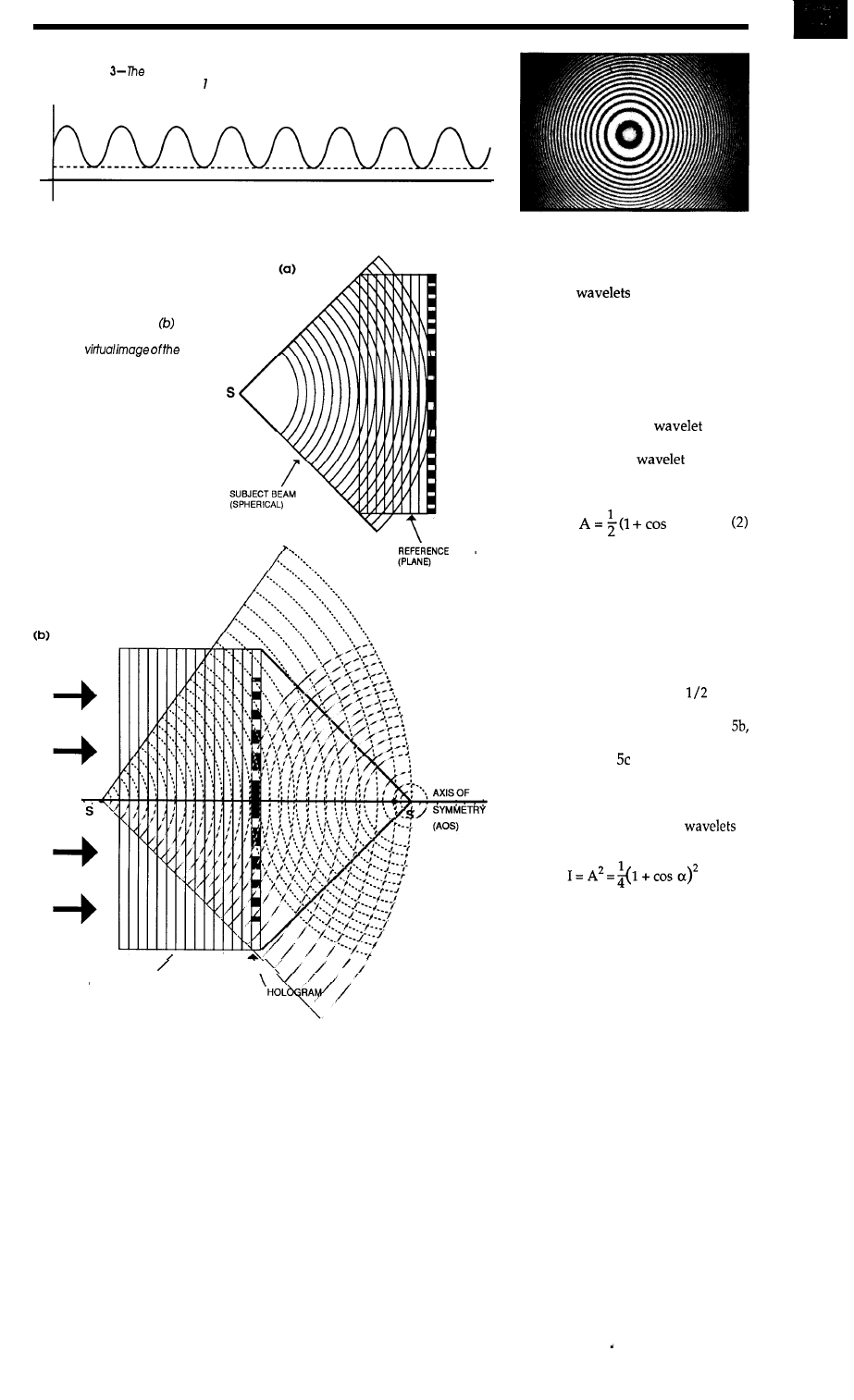
Figure
frequency of the amplitude transmission across the surface
of the grating in Photo represents the spatial frequency of the grating.
Photo 2-A
hologram of a point consists of
concentric circles on the film.
Figure
4-_(a) A hologram of a
single point consists of alternately
light and dark circular fringes and
is called a zone plate. When
the processed hologram is illumi-
nated, a
origi-
nal point is formed.
BEAM
ILLUMINATING
\
BEAM
same wavelength) and the interaction
of these
is responsible for
interference effects observed. Figure
5a illustrates the principle. Here a
plane wave illuminates an opaque
screen with a pinhole in it. The pin-
hole acts as a new source of spherical
waves as shown by the segments of
circular arcs. The small circle repre-
sents a secondary
of the
spherical wavefront. The amplitude
of this secondary
is not the
same in all directions but varies ac-
cording to:
a)
where A is amplitude and a is the
angle at which the radiating ampli-
tude is to be calculated. This equation
is known as the obliquity factor. The
obliquity factor has a maximum value
of 1 which occurs when
a =
0, corre-
sponding to the direction of travel of
the source. At 90 degrees the obliq-
uity factor gives a value of
and at
180
degrees
the obliquity factor is zero
indicating that, as shown in Figure
there is no wave in the backward di-
rection. Figure is a polar graph of
the amplitude and intensity distribu-
tion as predicted by the obliquity fac-
tor. It follows from Equation 2 that the
intensity of the secondary
is
given by
In this respect we can ignore the
light source once the coherent
wavefront isdefined at the diffracting
aperture(s). The Fresnel zone plate is
a patternof concentric transparent and
opaqueringsdesigned tofocusabeam
of plane wavefronts incident upon it
April/May 1990 25
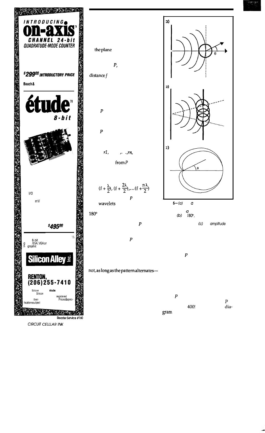
4
Acquires and displays position infor-
mation from optical encoders. Resolu-
tion is four times the encoder. Com-
plete with demo software and driver
source code.
(add $150 for optional connector to
Lomb “glass scales”.)
25 MHz
ANALOG-TO-OIGITALCONVERTER
Based on the TRW THC1068 hybrid
flash converter, its high signal-to-noise
ratio yields excellent accuracy at the
Nyquist limit.
n
4 KB of cache SRAM or to host as
converted at DMA speed
n
or DMA data transfer
n
10 MHz full-power bandwidth
n
3.92
resolution
n
Factory calibrated
n
16 jumperselectable base addresses
n
External clock and trigger inputs
TTL compatible
n
Software source code included
P R I C E :
Each product requires PC compatible
length
expansion slot. DOS 2 11 or
reater
Herculesdisplayneeded
or
representation of data.
P.O. BOX 59593
WA 96956
01990
Alley Inc.
and on-axis are
trademarkof
Alley Inc. Other brand or prod-
uct names are trademarks or
trade-
marks of
respective holders.
to change.
much like a magnifying lens. To de-
rive some very important properties
of the Fresnel zone plate we will di-
vide a plane wavefront into the vari-
ous zones as shown in Figure 6. We
can assume that the entire flat surface
of
wavefrontconsistsof tiny
point sources of light, each emitting
spherical wavelets. Now consider
some point illuminated only by
light from the wavefront, located a
past the wavefront as illus-
trated. We now will divide a portion
of the wavefront into zones such that
there is a maximum concentration of
light produced at point P. This is
done by allowing only the portions of
light emitted from the wavefront to
reach that would interfere construc-
tively with any other light from the
wavefront reaching P. Referring to
Figure 6, consider the perpendicular
from to the plane wavefront. The
intersection with the wavefront is
denoted by 0. We now divide the
plane wavefront into series of circles
of radii
r2, r3 .
centered at 0
such that each circle is a half wave-
length
further
than the preced-
ing one. We now can see that the
circles, beginning with the innermost
circle, are at distances
from
P.
The phases at of any secon-
dary
from any given circu-
lar zone will not differ by more than
(one half wavelength). If we go
from one zone to the next, the ampli-
tude of the wave reaching changes
sign. Therefore, if we block every
other zone, only constructive inter-
ference will occur at (considering
only the portion of the wavefront
encountering the zone plate). The
result of thisconstructionist Fresnel
zone plate. It does not matter if we
start by blackening the center zone or
remember, intensity is proportional
to the square of the amplitude.
This discussion should also sug-
gest that the performance of a holo-
gram is unaffected if its
dark and light
areas are interchanged. This is in-
deed the case-a hologram does not
produce negatives. It is informative
Figure
As plane wave illuminates
an opaque screen with a pinhole, the pin-
hole acts us new source of spherical
waves. At
the obliquity factor is
zero. indicating that there is no wave in the
backward direction. The
and
intensity distribution as predicted by the
obliquity factor is plotted on a polar graph.
to look at some actual magnitudes in-
volved with the zone plate. For only
the first zone, it can be shown that the
intensity at is increased four times.
This is rather
surprising for the case of
an opaque center zone since this im-
plies that there should be a bright spot
in the center of the shadow cast by an
opaque circular obstacle. This is in-
deed the case and the placement of
such a single disk increases the inten-
sity at by four. For a zone plate with
only 20 zones, the intensity at is
increased by
Looking at the
of Figure 7, we see that a series of
26
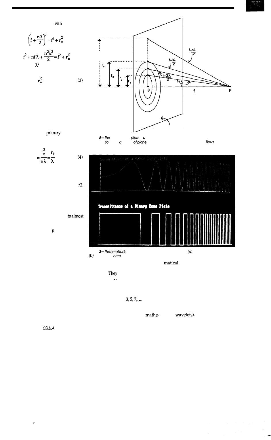
right triangles are formed. For the
triangle formed by the
radius, we
have, from the Pythagorean theorem:
Eliminating since this value is neg-
ligible for light:
= nfh
We now have a simple formula
for constructing a Fresnel zone plate
with desired properties. For example,
if the above-mentioned zone plate of
20 zones were to focus the light from a
He-Ne laser at 10 cm, the entire zone
plate would have a radius of only
about 1 mm. If we solve the zone plate
equation for f, the
focallength,
a very convenient and useful formula
is obtained:
2
f
We will make much use of this
relationship. Consideragainthepoint
P
when the plane wave is encounter-
ing a single opaque zone of radius
As previously stated, the intensity is
four times as great as that which re-
sults from the plane wave alone. Now
if the radius of the opaque disk is
expanded to cover the first two Fresnel
zones, theintensityat Pdrops
zero. If we continue this process of
increasing the radius of the opaque
disk, the intensity at goes through a
series of maxima and minima as the
number of zones included according
to the formula becomes even or odd.
The result is the same if an open aper-
ture is used allowing only increasing
circular areas of the plane wavefront
to emerge while blocking the rest.
Because of the abrupt changes
between transparency and opacity in
the Fresnel zone plate, there will be re-
gions of secondary concentrations of
light. A series of secondary foci along
the axis between the primary focal
point and the zone plate are readily
observed if a white card is moved
along the area. These foci are fainter
PLANE WAVEFRONT
Figure
Fresnelzone
is pattern of concentric transparent and opaque rings
designed focus beam
wavefronts incident upon it much
magnifying
/ens.
Photo
transmissions of a Gaborzone plate and a Fresnelzone plate
are shown
than the point at
P
and progressively
diminish as the zone plate is ap-
proached.
are
found at distances
f/3, f/5, f/7,.
If you give the above
discussion a little extra consideration
you will realize that these secondary
foci are produced by single zones
acting in groups of
There also exist various light
concentrations at points off the axis of
the Fresnel zone plate. The
analysis of these off-axis
maxima and minima are very com-
plex, the results of which verify the
presence of concentric circular fringes
centered on the axis. These secondary
foci do not occur in the holographic
zone plate. The sinusoidal variations
in the opacity of fringes causes cancel-
lation of these higher order diffrac-
tions (by superposition of the secon-
dary
Photos 3a and 3b
28
CIRCUIT
R INK
illustrate respectively the amplitude
transmission of a
zone plate
and a Fresnel zone plate. A sinusoidal
zone plate is also called a
zone
plate. It should be interesting to
compute the concentrations of light
produced by a
zone plate by
using as parameters the secondary
wavelets, obliquity factor, and sinu-
soidal transmission of the film.
To make a distinction between
diffraction and interference, diffrac-
tion refers to the situation
very
large number of tiny
of a
wavefront, such as the Huygen secon-
dary wavelets, are summed (inte-
grated) to produce a the pattern while,
interference refers to the interaction
(simple addition) of a smaller number
of beams. Briefly, the hologram inter-
ference pattern will be calculated by
summing all of the sinusoidal waves
emitted from each point of the object
and calculating the resultant phase
and amplitude at the hologram sur-
face and then assigning either trans-
parency or opacity at that point. This
summation is done for each point.
PRELIMINARY CONSIDERATIONS
The procedure used to produce
the computer-generated holograms
willconsistofthefollowingthreesteps:
An optical interference pattern
of a mathematically represented scene
is computer calculated by digital ap-
proximation. This interference pat-
tern is of the type produced by an
axis holographic recording process.
The pattern is then reduced
photographically thus becoming a
transmission hologram designed to
be viewed with laser light.
This pattern is then drawn on a
screen or plotter producing a mono-
chromatic output.
Consideration of the standard
recording process of an off-axis trans-
mission hologram reveals some diffi-
culties that will be encountered in
reproducing the process by artificial
means. We have seen that this proce-
dure produces an extremely fine in-
terference pattern. Specifically, Equa-
tion 1 implies that, when the angle
between the two recording beams
approaches
the fringe spacing
approaches that of the wavelength of
the light involved, which for a He-Ne
laser corresponds to about 1600
pairs/mm. Such large angles are
required because it is desirable for the
off-axis scene to be near the film, thus
permitting a large angular viewing
range. This necessitates an extremely
high resolution film such as the Kodak
649F Spectroscopic emulsion which is
capable of resolving a maximum of
7000 line-pairs/mm. A x 5-inch
hologram with a maximumdeflection
angle of 60” will be required to record
about 132 billion dots.
The hologram also records a gray
scale. If 64 levels of gray are assumed,
the effective data content exceeds 8
trillion
(These
calculationsareveryconservative. To
prevent aliasing errors, the resolution
in each direction should be at least
doubled, and preferably quadrupled.)
The size of the hologram is significant
because the observer moves his head
during viewing to exploit parallax.
The dimensions of the hologram
should thus be considerably larger
than the separation of one’s eyes.
The calculation time of the com-
puter-generated holograms will be
decreased by reduction of the follow-
ing four parameters:
Now consider the time required
to numerically calculate the data con-
tent for a hologram of a typical (small)
object consisting of 1 million resolu-
tion elements. This means that there
would be
calculations re-
quired foreachof the 132billionpoints
of the hologram. Although the laser
would produce this data instantly on
a photographic emulsion (the highest
information storage material known),
the process would take a computer,
working at a rate of one million calcu-
lations per second, over 4000 years!
size-The holograms
will be no larger than the standard
frame size of the popular 35mm film
(36 mm x 24 mm).
Quantify of resolution elements of
subject-The subject will be a simple
geometrical shape such as a circle con-
sisting of only a few pixels.
Angles between object and reference
maximum angle here will
SAVE Development
and Debugging Time
of Embedded
Microprocessor Systems!
l
INTROL-C Cross-Compilers
l
INTROL-Modula-2
Cross-Assemblers-
COMPILER PACKAGES INCLUDE:
Compiler
l
Assembler
l
Linker
l
library, including
a multi-tasking executive
l
Support utilities
l
Full year’s
maintenance
TARGETS SUPPORTED:
l
l
6809
l
l
l
AVAILABLE
FOLLOWING
HOSTS: VAX and
Apollo; SUN; Hewlett-Packard;
Macintosh; Gould
Node; IBM-PC, XT, AT, and
compatibles
CROSS-DEVELOPMENT
SYSTEMS are proven, accepted
and will
save
time, money,
and effort with your develop-
ment. All
products are
technical support.
for facts NOW!
9220 W. Howard Avenue
Milwaukee, WI 53228
FAX:
April/May
29
be minimized for a given fringe spac-
ing of the hologram.
Gray
will be no gray
scale. The hologram will consist of
only transparent or opaque areas.
There is a very mysterious and little
known property of holograms that is
of great significance in this applica-
tion: The gray scale of the subject is in-
dependent of the gray scale of the
hologram. One may deduce that if the
hologram is of binary form, then the
reconstructed image must also be
binary in nature. This is not the case.
The reconstructed image may have a
continuous gray scale regardless of
the binary nature of the film. Any
level of brightness that is assigned to
any pixel in the recording process is
stored in its relative proportion in the
wave summation over the entire holo-
gram area.
HARDWARE CONSIDERATIONS
Holographic patterns will be
drawn using the following three types
of output devices:
A standard VGA display of 640 x
480 dot resolution and hologram reso-
lution (640 x 427).
A pen plotter with an effective
plot area of 864 mm x 546 mm and
mm resolution with a 0.3-mm tip di-
ameter pen giving a hologram
A multihead laser plotter with an
effective plot area of
resolution giving a holo-
gram resolution of 48000 x 32000
x
The effective plot area of each
device is shown in parentheses
to obtain a width-to-height ratio of
that equal to the standard 35mm film
frame
This clipping represents
a
significant time savings when the
reduced pattern is to be of maximum
size (36 mm x 24 mm).
I used technical pan film to photo-
graph the holographic interference
patterns since this
able and can resolve up to 400
pairs/mm at various contrast levels.
This film is also ideal for applications
involving a He-Ne laser as it has a
high sensitivity to light in the red
portion of the spectrum. Ektagraphic
HC slide film might also be used be-
cause of its 750 line-pair/mm resolu-
tion.
REDUCTION METHOD
Because we are creating a holo-
gram artificially by imitation of the
actual process on a large scale and
then reducing it for illumination with
the light from a He-Ne laser, we must
consider what effect reduction of the
pattern as well as reduction of the re-
cording wavelength has on the final
image. Keeping in
mind that
in the
plotting process, a large wavelength
(imaginary, of course) can be associ-
ated with the recording pattern, we
will look at the effect, on the recon-
structed image, of reducing the holo-
gram pattern as well as the recon-
structing wavelength.
To simplify matters for illustra-
tion, suppose that the object consists
of a single point A as illustrated in
Figure 7. We know the values of the
EXPRESS CIRCUITS
MANUFACTURERS OF PROTOTYPE PRINTED CIRCUITS FROM YOUR CAD DESIGNS
TURN AROUND TIMES AVAILABLE FROM 24 HRS
2 WEEKS
Special Support For:
l
TANGO.PCB
l
TANGO SERIES II
l
TANGO PLUS
l
PROTEL AUTOTRAX
l
PROTEL EASYTRAX
l
l
l
EE DESIGNER I
l
EE DESIGNER III
l
PADS PCB
l
OTHER PACKAGES ARE
NOW BEING ADDED
l
FULL TIME MODEM
l
GERBER PHOTO PLOTTING
Express
Circuits
314 Cothren St., PO. Box 58
Wilkesboro, NC 28697
Quotes:
l-800-426-5396
Phone: (919) 667-2100
Fax: (919) 667-0487
30
CELLLAR INK
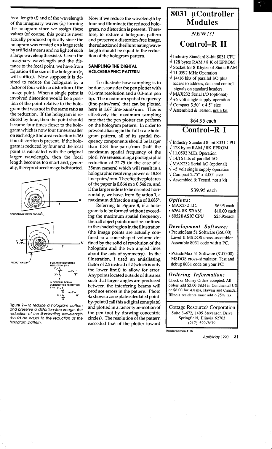
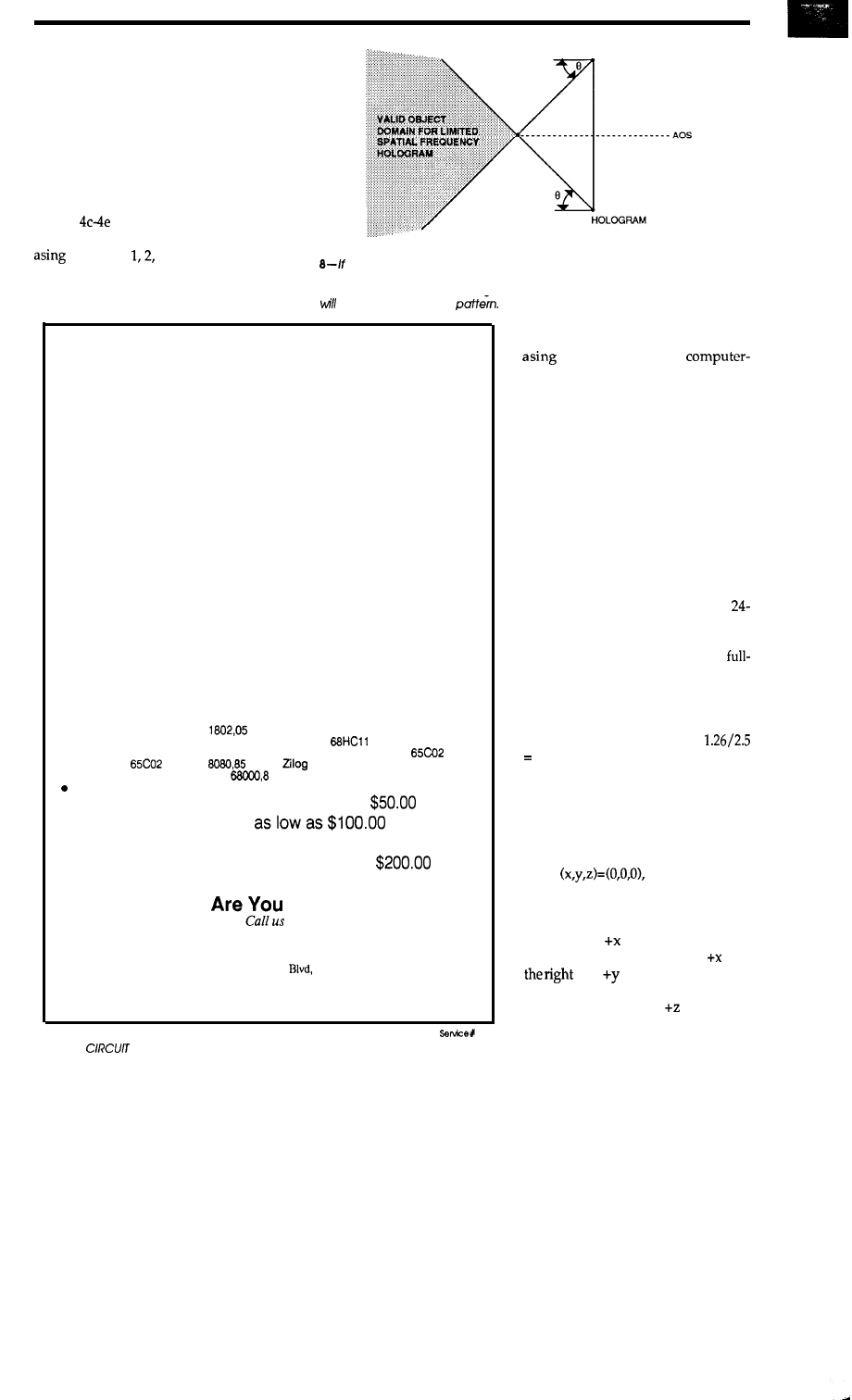
the
edges of the plot. Notice how the
jagged edges arrange themselves to
produce several families of secondary
zone plates. When this pattern is illu-
minated with laser light, each of these
secondary zone plates has a focusing
effect, and the error emerges as a
matrix of concentrations of light (sec-
ondary foci) about the primary center
focal point as shown in Photo 4b.
Photos
illustrate zone plate for-
mation on a VGA screen with antiali-
factors of
and 3. As can be
seen,
the aliasing error decreases (less
Figure
a hologram is to
be formed without exceeding the maximum spatial
secondary zone plate contrast) as the
frequency, then all object points must be confined to the shaded region.
Any points
located outside this area such that larger angles are produced between the interfering
antialiasing factor increases. From
beams
produce errors in the
GET TO WORK!
A New Project
Our line of macro Cross-assemblers are easy to use and full featured,
including conditional assembly and unlimited include files.
Get It To Market--FAST
Don’t wait until the hardware is finished to debug your software. Our
Simulators can test your program logic before the hardware is built.
No Source!
A minor glitch has shown up in the firmware, and you can’t find the
original source program. Our line of disassemblers can help you
re-create the original assembly language source.
Set To Go
Buy our developer package and the next time your boss says “get to
work”, you’ll be ready for anything.
Quality Solutions
PseudoCorp has been providing quality solutions for microprocessor
problems since 1985.
BROAD RANGE OF SUPPORT
.
Currently we support the following microprocessor families (with more in
development):
Intel 8048
RCA
Intel 8051
Intel 8096
Motorola 6800
Motorola 6801
Motorola
Motorola 6805
Hitachi 6301
Motorola 6809
MOS Tech 6502
WDC
Rockwell
Intel
280
NSC 800
Hitachi HD64180
Motorola
Motorola 68010
All products require an IBM PC or compatible.
Cross-Assemblers
as low as
Simulators
Cross-Disassemblers
as low as $100.00
Developer Packages
as low as
(a $50.00 Savings)
So What
Waiting For?
PseudoCorp
Professional Development Products Group
716 Thimble Shoals
Suite E
Newport News, VA 23606
(804) 873-1947
this data, I decided to use an antiali-
factor of 2 for the
generated holograms.
SYNTHESIZING A HOLOGRAM
Let’s start
our example by calcu-
lating the interference pattern for a
hologram of a computer-generated
curve (a three-leaved polar rose). Here,
the situation for the VGA display (640
dots horizontally by 480 dots verti-
cally) is used. These displays are
usually about 10” x 7.5”. Because the
width/height ratio is lightly different
than that of a 35mm camera, when
photographing with a 36-mm x
mm viewfinder, simply fill the area
vertically. Ideally there will be a small
vertical strip along one edge of a
scale (36 mm x 24 mm) hologram, but
all pixels will be used. The spatial fre-
quency of a VGA display is about 1.26
line-pairs/mm. We will divide this
value by 2.5 to prevent error:
0.504 line-pairs/mm. I will conser-
vatively round this value to 0.5 in
actual calculations.
The hologram plane is defined in
a three-dimensional Cartesian coor-
dinate system as illustrated in Figure
9. The origin of the system has coordi-
nates
with the coordi-
nate signs assigned as implied by the
drawing. The hologram plane coin-
cides with the xy plane with its top
edge on the axis and upper-left
corner at the origin. Note that is to
and isdownward to match
the native coordinate system of the
computer display. The direction is
32
CELLLAR INK
Reader
155
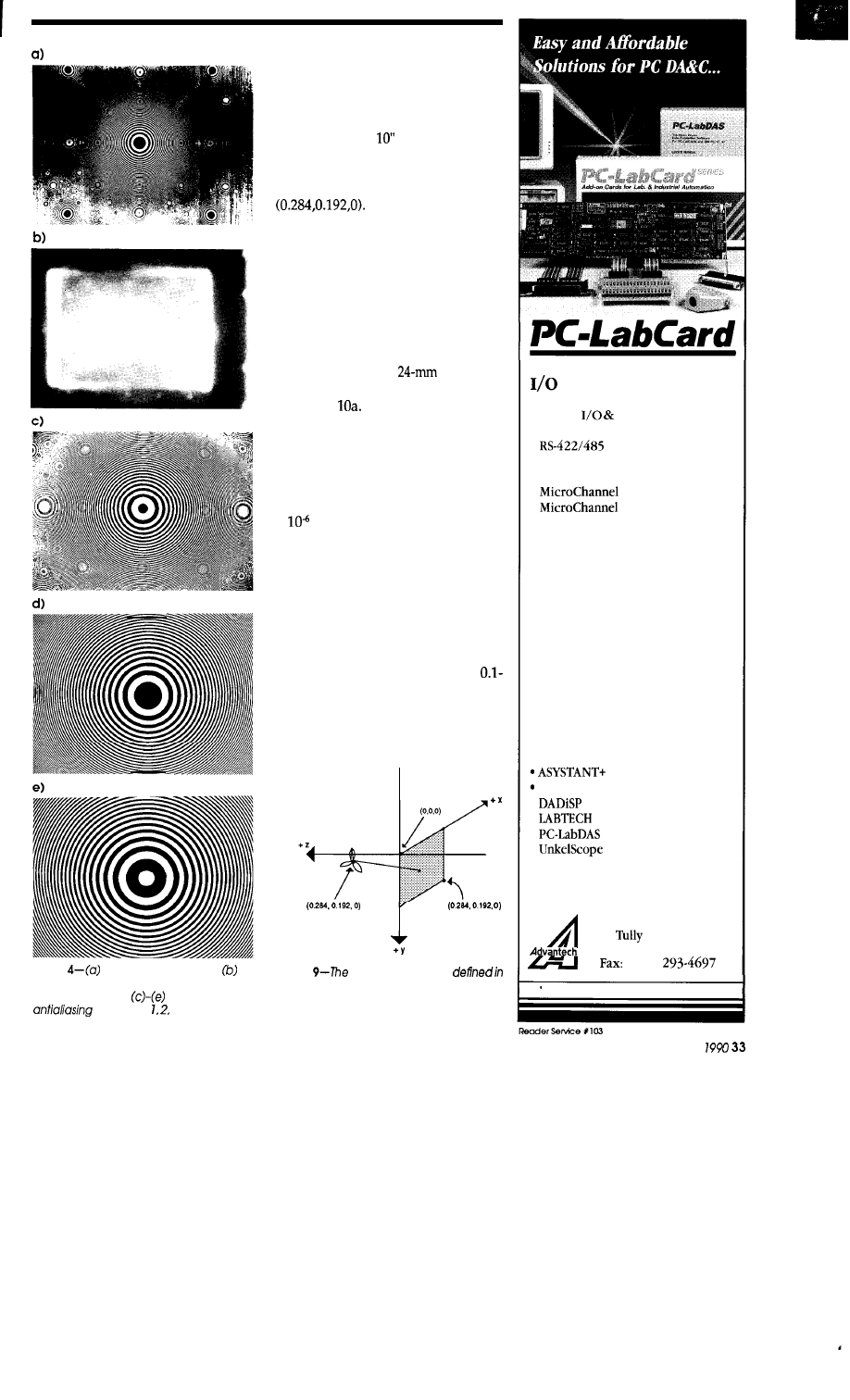
Photo
A typical zone plate. The
maxtrix of dots are errors caused by secon-
dary zone plates.
Zone plates with
factors of and 3.
toward the rear looking through the
hologram plane. The coordinates of
the lower right corner of the hologram
extent have VGA coordinates
(639,479). The screen size photo-
graphed will be (0.254 m) by 7.5”
(0.192 m). The position, in three-di-
mensional space, of the lower-right
corner of the hologram is located at
Let’s give the rose a
radius of 0.1 m and let it consist of
about 41 (I incremented the full polar
rotation of pi by0.075) equally spaced
pixels of equal intensity (more on in-
tensity assignments shortly).
We will now consider how close
the reconstructed
image
can
form from
the hologram plane. If the
entire
screen
of 0.254 m x 0.192 m is to be reduced as
to just fill a 36-mmx
film frame
then the reduction factor is 8, as shown
in Figure
This will result in the
0.500 line-pairs/mm of the plot to be-
come about 4 line-pairs/mm in the
final hologram. We also know that the
synthetic wavelength should be eight
times that of the reconstruction (he-
lium-neon laser) wavelength, or 5.0624
x
m. Equation 4 tells us that the
maximum angle that the hologram
can deflect the reconstruction beam is
about 0.146”. This corresponds to a
minimum object distance (on the plot
scale) of about 63 m if the maximum
hologram radius is, using the diago-
nal, 6.25”. Notice that an additional
39.52 m must be added to the mini-
mum object distance if the entire
m rose is to be recorded. Since it
would be desirable for the image to be
somewhat closer to the hologram, let’s
look at a reduction twice as great.
CENTER
Figure
hologram plane is
a three-dimensional Cartesian coordinate
system and is shown as the shaded region.
Cards:
l
A/D, D/A
l
Digital
Counter
l
IEEE-488 Interface
l
Comm.
l
Stepping Motor Control
l
Prototyping
l
Digital I/O
l
GPIB Interface
Daughter Boards:
l
Amplifier/Multiplexer
l
Wiring Terminal
l
Opto-Isolated D/I
l
Relay Output
l
SSR Output
Industrial Computer:
l
Industrial Computer Chassis
l
Computer Card Cage
l
Slot Extension Kit
l
CPU Card
l
RAM/ROM Disk Card
Software Support:
l
AMS (Strip Chart Recorder)
ASYSTANT GPIB
l
l
NOTEBOOK
l
l
CALL FOR FREE CATALOGS!
(408) 293-6786
American Advantech Corp.
A
1460
Road, Suite 602
San
Jose, CA 95122-9967
(408)
Dealer and OEM Inquiry Welcome
April/May
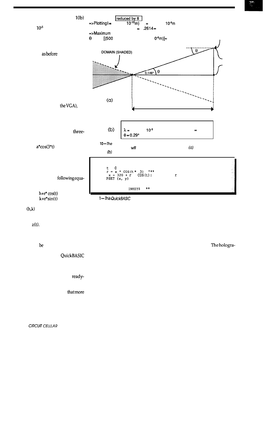
A reduction of 16 (Figure
corresponds to a synthetic wavelength
of 1.0125 x
m and a maximum
deflection angle of 0.29“. This brings
the minimum large-scale image dis-
tance down to 31.5 m. However, we
now have only one quarter of the
hologram area
(when photo-
graphed, the image seen through the
camera’s viewfinder should occupy
one quarter of thearea). After review-
ing the parameters for reductions by
24 and 32, I decided to use 16.
When writing the graphics rou-
tines, it would be much more conven-
ient to work in units of pixels rather
than meters-since 0.254 m corre-
sponds to 640 pixels (for
we
have the relationship 2520 pixels/m.
Now we can simply multiply any
meter value by 2520 to work directly
in graphics mode.
The polar equation of the
leaved rose is:
r =
where r is the dependent variable, f is
the independent variable, and a is the
radius of the rose. The transformation
from polar to Cartesian coordinates is
accomplished with the
tions:
x(t) =
y(t) =
where
is the center of the rose.
We could tilt the figure out of the
xy plane by adding a sinusoidal
function
However, because in
thisexamplethe hologramisrelatively
course and the object is small and
distant from the hologram plane, this
tilt would not very noticeable in the
reconstruction.
Listing 1 is a simple
program that will allow the user to
define and edit a holographic image
before it is processed by the program
of Listing 2, which draws the
to-photograph holographic interfer-
ence pattern on the high-resolution
graphics screen. Remember
points in the image means longer
drawing time. With a math coproces-
sor in a 286 machine running at 12
MHz, the rose plot takes about 12
34
INK
VGA plot to be
(6328 x
(8) 5.0624 x
maximum spatial frequency 1
0.315 line-pairs/mm
deflection angle:
= sin-’
line-pair/m) (5.0624 x 1
0.146’
VALID OBJECT
HOLOGRAM
0.161 m
63 m
(OBJECT DISTANCE)
VGA Reduction by 16:
1.0125 x
object distance 31.5 m
Figure
amount ofreduction used when making the hologram affects how close
the reconstructed image be to the hologram plane. Part shows a reduction factor
of 8, while shows a factor of 16.
SCREEN 12: COLOR
4: pi = 3.1416: a = 12.5
FOR = TO 1 *
pi
STEP 0.02
PLACE ANY FUNCTION HERE **
*
y = 240 + * SIN(t)
NEXT t
DO: LOOP WHILE
=
listing
program allows the user to define and edit a holographic
image before it is processed.
hours to complete.
Without the
coprocessor, it takes several days.
In defining the interference pat-
tern, each point of the rose is consid-
ered to be emitting light, thus illumi-
nating the hologram plane with radia-
tion of the synthetic wavelength. Each
point emits light with a specified ini-
tial phase and reaches each point of
the hologram plane with a specific
phase. For each point in the hologram
plane, the sum of the waves from each
point of the circle is calculated and the
point is assigned to be either transpar-
ent or opaque depending upon the
result of the summation. There is also
a phase value present at the hologram
plane. For simplicity, I assigned a
phase value of zero at the hologram
plane and let all points on the rose
start emission with a sine wave (0
initial phase angle and increasing
amplitude) of unit amplitude. At the
hologram plane opacity was assigned
if the wave summation at that point
was greater than or equal to zero and
transparency otherwise.
pher can choose any trigger level
desired. Also, different points of an
object can be assigned various ampli-
tudes for a proportional intensity in
the reconstructions.
Another consideration in the re-
construction of the image of a binary
hologram is the formation of extrane-
ous images due to higher order dif-
fractions. From the experiments per-
formed here, these higher order dif-
fractions were so dim that they were
unnoticeable. However, Equation 1
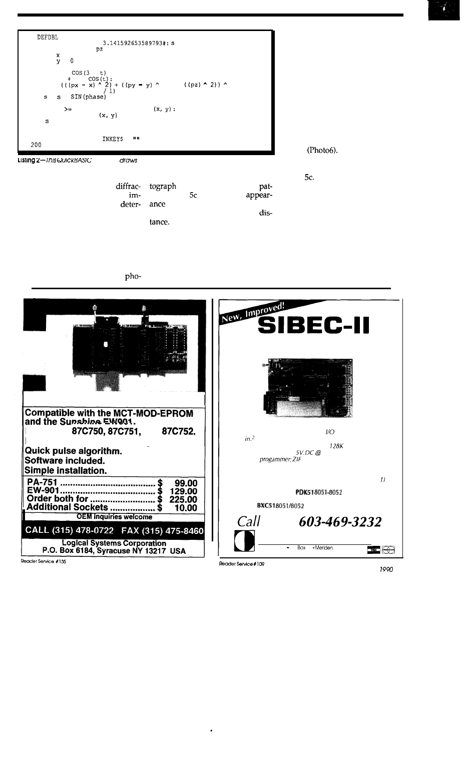
5
A-Z
10 SCREEN 12: pi =
= 0: CLS
20 1 = 0.0255145:
= 129528: h = 320: k = 240: a = 252
30 FOR = 0 TO 639
40 FOR = TO 479
50 FOR t = 0 TO 1 * pi STEP 0.075
55 r = a *
*
60 px = h r *
py = k t r * SIN(t)
70 d =
2) t
0.5
80 phase = (2 * pi *
d
9 0 = +
100 NEXT t
110 IF s
0 THEN COLOR 7: PSET
GOT0 130
120 COLOR 0: PSET
130 = 0
135 NEXT y
140 NEXT x
150 DO: LOOP WHILE
=
END
program
the ready-to-photograph holographic interfer-
ence pattern on the high-resolution graphics screen.
may be used to calculate the
of the actual interference
tion angles of the second-order
tern. Photo illustrates the
ages in the reconstruction to
of the reconstructed real image
mine an object size (or fringe spacing)
projected at the predicted focal
to ensure distortion-free images.
VGA-RESOLUTION HOLOGRAMS
Observation of the pattern of the
on-axis hologram has a somewhat
AND RECONSTRUCTIONS
fuzzy outline of the rose, and one may
think that the image is formed by light
Photo 5a shows the subject of the
rays passing straight through the
first hologram and Photo 5b is a
film-this is not the case as can be
easily shown in several ways. First,
the pattern is not sharp and can’t
produce the observed bright points of
light by projection. Secondly, if the
image is viewed between the holo-
gram and the focal point, only a blur
appears.
For a more dramatic illustration, I
cut the hologram into quarters and the
full image was reproduced in each
piece. To illustrate this further, I plot-
ted a small offset segment of the holo-
gram having none of the rose-shaped
outline
When illuminated,
this (now offset) hologram fully re-
produces the rose as illustrated in
Photo Also, the distant virtual
image of the rose can be seen by look-
ing through the hologram toward the
illuminating laser.
The hologram
shows off-axis properties with less
than one-third of VGA resolution!
Photo 6 can be photographed and
used as a hologram. If this is done, the
final image making up the fringes
should be 0.32” x 0.25”. It should be
photographedwithalightbackground
which will become a dark outline for
876751 ADAPTER
Programs
and
No need to remove from programmer.
The ideal solution for embedded control
applications and stand-alone development.
l
Intel 8052AH BASIC CPU
l
Serial printer output and 5, 8 bit
ports
l
5
prototyping area
l
Memory: 8K RAM, expandable to
. Power requirements:
300 ma. only
l
PROM
socket for 2764 or 27128 EPROM
. interrupt handling capability
l
Built to exacting standards and warranteed
l
Still only $228.00 including documentation (quantity
Inquire about our
product
development kit for the
IBM-PC/XT/AT: $595.
Our
BASIC compiler: $295.
now!
Binary Technology, Inc.
Main Street PO
67
NH 03770
A p r i l / M a y
3 5
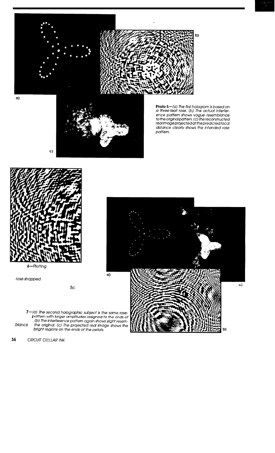
Photo
a small offset of
the interference pattern shown in
Photo 5b eliminates any hint of the
outline. When i//u-
minuted, the projected real im-
age is identical to that in Photo
Photo
shapped
the petals
to
expected
blocking extraneous laser light when
viewing the hologram. It appears that
any type of black-and-white film can
be used for the VGA holograms.
I also plotted the negative of the
pattern simply by reversing the pixels
(turning blank pixels on and turning
lighted pixels off). The negative pro-
duced results identical to those just il-
lustrated.
For the next hologram, I assigned
a higher brightness to a few of the
pixels making up the rose. Pixels
making up three small segments of
the rose were assigned larger ampli-
tudes (all others are normally unity).
Photo 7a illustrates the rose with sev-
eral brighter pixels. Photo 7b shows
the resulting holographic pattern and
Photo is its reconstruction. The sets
of two, three, and four bright pixels
were assigned amplitudes of three,
four, and five, respectively.
The experiments presented here
show that in holography the
mentsof coherence, stability, and
resolution recording media are not as
strict as many people believe.
THE FUTURE
Holographic display devices may
have a bright future. The nature of
such a device will operate on drasti-
cally different principles than the CRT
(pixels emit incoherent light),
blyusinga sort of supercomputer (par-
allel processor) to calculate an inter-
ference pattern in a reasonable span of
time. There will
a great change
in the manner in which graphics im-
ages are created on these devices.
Obviously, no image is drawn on any
surface-only an interference pattern.
The entire image will be present or
not-nowhere in between. A feasible
construction would be a display ma-
trix consisting of liquid crystal “shut-
ters” that could be toggled open or
closed. The matrix would be illumi-
nated by spread (no eye hazard) laser
light from behind. The shutters need
not cover the entire display surface
since their purpose is only to direct
light. Several cluster arrangements,
each consisting of shutters of close
spacing, would be suitable.
Full-color holographic displays
can be produced by use of illuminat-
ing lasers of the primary colors. Color
holograms are calculated by assign-
ing each pixel three synthetic wave-
lengths, each corresponding to one of
the primary colors. The waves would
be of amplitude characteristic of the
object point. The monochrome inter-
ference pattern is then capable of
producing the scene in full color.
like
special thanks to
ing people for their patience and
in
this project: May Lou Nassar, Maria Palmer,
Joe Lombardo, and Charles Palmer
Dale Nassar has a B.S. in physicsfrom South-
eastern Louisiana University
His
hobbies include gymnastics (university team)
and springboard diving.
IRS
207
Very Useful
208 Moderately Useful
209 Not Useful
AND
EMULATORS
The
and
are low-cost real
time in circuit emulators for the Motorola
and
families of single chip microcomputers. Any host
computer with a serial port and terminal emulation
software can be used with these emulators. Complete
development system software is included for MS-DOS
based computers. The base prices are $1195 for the
HC05 and $995 for the
1.
/NC.
BOX 8C
l
Barton,
05822
Phone (802) 525-3458
l
Fax
(802) 525-3451
Turn you PC into a powerful imaging workstation
with a Video Frame Grabber
h Res Technolo
Take
Choice
of Four
NTSC (U.S.) PAL (European)
compatible
Output Look Up Table
on
purchase in
first year return of old
and
just pay
Software library of image analysis
routines,
demo and
utilities all included free
Free
upgrades to
registered
how
can get results for
Talk to an
specialist
today.
HIGH RES TECHNOLOGIES
P.O. Box
76
l
Lewiston. NY
14092
Phone:
(416) 497-6493
l
Fax:
April/May
37
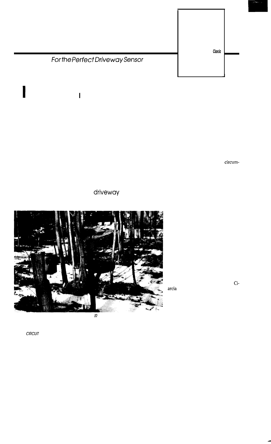
FEATURE
Modulating Laser Diodes
ARTICLE
Steve
The
Search
t all started when bought one of those Radio
Shack infrared doorway detectors and tried to use
i t a c r o s s m y d r i v e w a y t o t e l l w h e n s o m e o n e a p -
proaches the house. It’s not that I don’t like sur-
prises, it’s just that any good home control system
should be aware of its perimeter property as well. At
least, that’s what I tell people who see the array of
sensors and devices lining the driveway. In actual-
ity, most of it is now an electronic graveyard con-
taining the remnants of many attempts to make a
no-fault organic/inorganic
sensor. Let me
explain.
The Circuit Cellar driveway
sensor
farm includes motion, modulated and unmodulated
interrupted beam.
and pneumatic
sensors.
38
CELLAR INK
Unlike the average colonial or
saltbox house you’d expect in New
England, I live in one of those strangely
shaped California contemporaries
more befitting a reclusive personality.
It affords spacious living and I don’t
have to see any neighbors. Unfortu-
nately, I can’t see my BOO-foot drive-
way either. When I go down in the
Circuit Cellar and turn on the stereo I
might as well be on another planet as
far as anybody pounding on the front
door is concerned.
A half dozen years ago
stancesmademe reevaluate ignorance
of above ground events. One time
while I was buried (figuratively) in a
project in The Cellar, a large truck
pulled into the
driveway and dumped
14,000 lbs of crushed stone. Later,
another truck dumped 8 cubic yards
of top soil. I just happened to go
upstairs in time to see a third truck
backing in with a load of landscaping
timbers.
I practically had to throw my body
across the hood of this truck to stop it
from being dumped next to the other
piles. Believe me, it was a real fight.
From the driver’s perspective I was in
the wrong, of course; after all, there
were two piles of stuff already on the
driveway. This had to be the right
place.
Shortly after that I decided the
only way to avoid similar situations in
the future was to apply the typical
response: massive intervention
of electronic countermeasures. To
keep a closer eye on ground level and
perimeter events, I installed a closed
circuit video systemand put monitors
in strategic locations. If I heard some-
thing or wanted to
check on outside
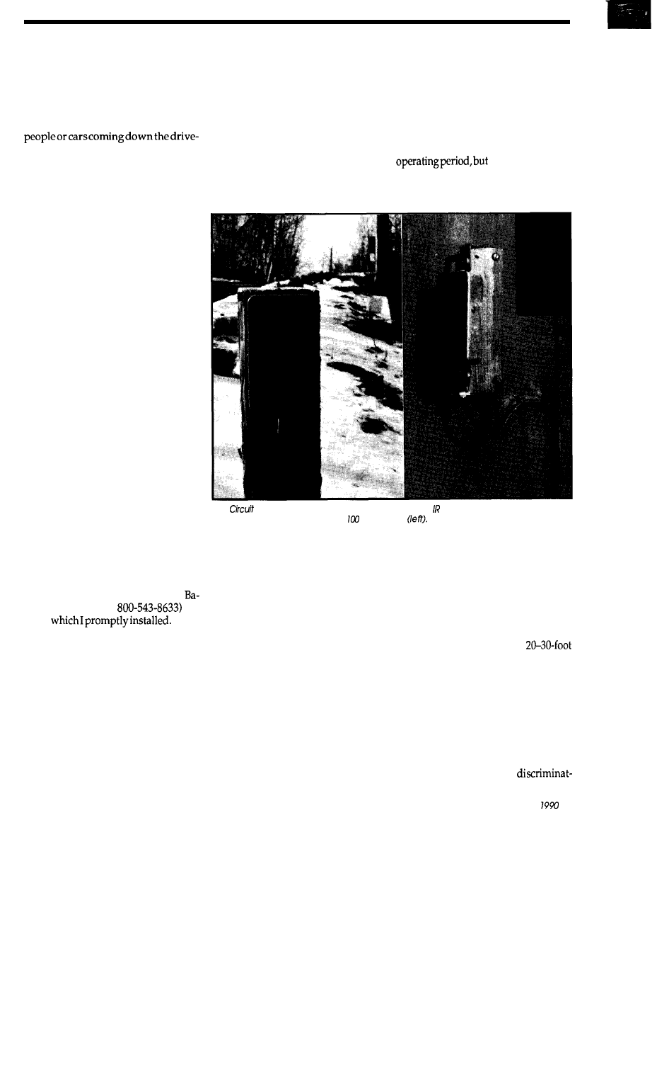
conditions without leaving my desk, I
merely looked at a monitor and
switched to an appropriate camera.
As a refinement to the system, I
installed devices in the driveway and
around the perimeter that triggered
control events when they sensed
way.
Without resorting to esoteric
“military budget” solutions involv-
ing strain gauges under the pavement
and hidden microphones with DSP
“signature-detection” electronics in
the bushes, or low-light-level CCD
cameras with video pattern recogni-
tion, I decided to attempt a more eco-
nomical perimeter intrusion detector
(I am working on a video digitizer/
DSP analyzer “seeing” detector as the
ultimate solution to this problem but
that is a future project).
A relatively simple combination
ofinfraredmotionorbeamsensorand
a magnetic coil sensor mounted in the
same physical location seemed to of-
fer a quick solution. A large steel
vehicle (inorganic) passing the sense
point would trigger both the infrared
and magnetic sensors (the magnetic
sensor is a coil of wire under the drive-
way with the electronics of a classic
metal detector; simple but effective).
A person (organic) passing the sense
point would trigger only the infrared
sensor. Simple binary logic and you
have both a people sensor and a ve-
hicle sensor.
Being a pessimist, I expected to
have a real problem building the
underground metal detector. Fortu-
nately, I found a off-the-shelf mag-
netic field “vehicle” sensor in a
Sporty’s catalog (Clermont Ave.,
tivia, Ohio 45103,
for
$159
Since
it worked like a charm with little
modification (provided you don’t
drive in on a lawn mower), I focused
my attention on the easy chore of
making an infrared driveway sensor.
After all, how difficult could it be? Go
down to your local Radio Shack and
buy one of those infrared door entry
sensors and mount it across the drive-
way? Or, how about a motion detec-
tor like the ones that trigger outside
lights?
TRUTH IN ADVERTISING
The first thing you should know
about practically all low-cost commer-
cial infrared sensors is that they’re ba-
sically good for nothing when used
outdoors. Spend a little time watch-
ing one of those IR motion detectors
when it is raining and see how many
times it triggers falsely. Or, drive
a
car
that has been sitting at ambient tem-
perature a few hours past a sensor
while the engine is still cold (what
enclosure (heated and cooled) and
perfectly aimed at an appropriate re-
flector across a driveway. Unfortu-
nately, in my experience, they lack the
signal-to-noise discrimination to deal
adequately with the dynamics of
bright daylight and seasonal changes.
Adding black tubular sun shields in
front of the lens extended the useful
there were times
when the ambient light completely
swamped the reflected signal and there
was no output (false-negative error>.
The
Cellar laser driveway sensor consists of an laser transmitter on the garage
(right) and a receiver on a post
feet away
car?). Of course, if the only repercus-
sion is that the porch lights are left on
for a couple extra minutes, we hardly
notice. Even when the light stays on
continuously we frequently don’t care.
(While I had some success with nar-
rowly aimed IR motion detectors, I
was never satisfied with the number
of false-positive errors).
In a world of real control applica-
tions, however, if such a detector trig-
gered several lighting control actions
in the house or opened/closed the
garage door, you’d notice false trig-
gering and errors immediately.
Indoor-use interrupted-beam
sensors hold a little more promise.
Withalittleworktheycanbemounted
in an environmentally conditioned
Instead of more efficient mirrors,
and so on, the solution to increasing
signal-to-noise ratio is to eliminate the
passive reflector and actively trans-
mit a bright modulated beam from the
opposite side of the road. This is, in
fact, the design basis of most indus-
trial IR beam sensors. Unlike the
indoor-use units that have
ranges using a reflector at the oppo-
site sense point, industrial interrupted
beam sensors generally use separate
IR transmitters and receivers and can
have ranges of hundreds of feet.
A CHALLENGE IN THE MAKING
Creatingbothasufficientlybright
IR source (signal) and a
April/May
39
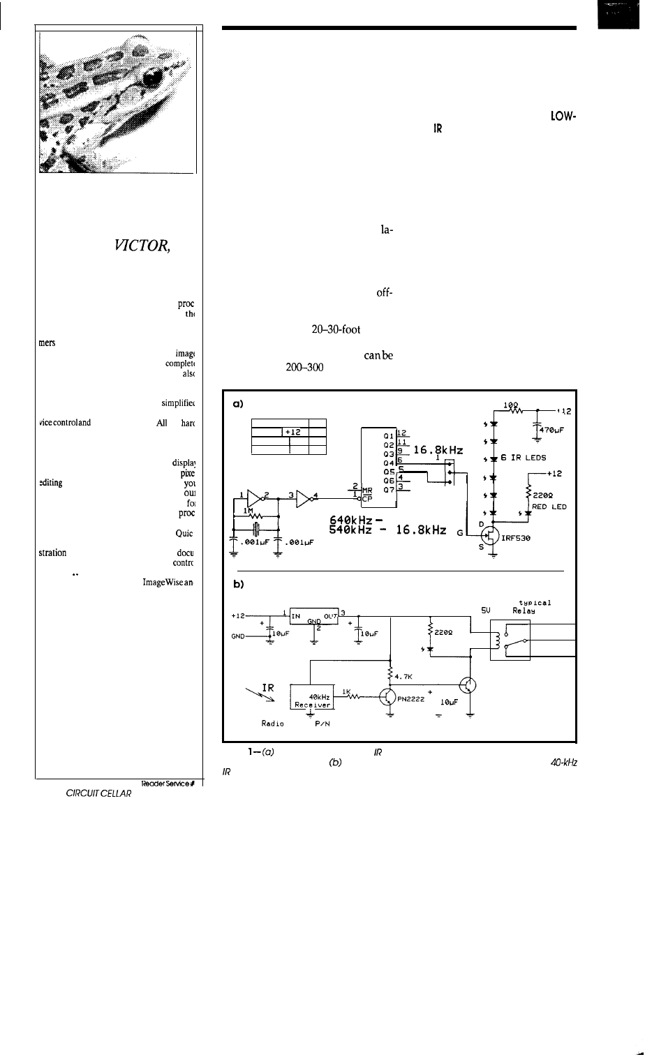
Develop powerful
image applications
quickly and easily
Introducing
the
video capture and image
processing library
VICTOR, the video capture and image
essing library, is the latest product from
developers of ZIP Image Processing software
Victor is a library of functions for C program
that simplifies development of scientific
imaging, quality control, security, and
database software. Victor gives you
control of your video frame grabber and
includes image processing, display, and TIFF
PCX file handling routines.
Application development is
because we’ve taken care of the details of de
image processing.
the
low level coding has been done -- and you car
concentrate on your application.
Yoursoftware can have features such as
live video on VGA, pan and zoom,
multiple images with text and graphics,
and image processing. And, to get
up and running quickly, we’ve included
popular Zip Image Processing software
rapid testing and prototyping of image
essing and display functions.
Victor supports Microsoft C and
C, and includes over 100 functions, demon
and prototyping software, full
mentation, and source code for device
routines.
all for only $195.
Victor and Zip support
other popular
video digitizers.
VICTOR LIBRARY $195
includes ZIP Image Processing
ZIP Image Processing $79
please specify digitizer
Video
frame grabbers are also available.
Call (314) 962-7833 to orde
VISA/MC/COD
CATENARY SYSTEMS
470 BELLEVIEW
ST LOUIS MO 63119
(314) 962-7833
4 0
INK
ing receiver which works under all
ambient lighting conditions (noise) is
no easy task, but it was a challenge. I’d
like to say that all my attempts were
successful, but they weren’t. Distance,
point-to-point elevation differences,
and weather all played a part in mak-
ing a simple proposition into a monu-
mental task (have you ever tried to
accurately aim a light beam, that you
can’t see, at a target 160 feet away?).
It would be a waste of article space
if I didn’t tell you that I was ultimately
successful. I did indeed create a brute
force industrial-strength infrared
serbeam sensor suitable for use across
hundreds of feet of open space in a
hurricane. Along the way, I devised a
couple of useful circuits for expand-
ing the capabilities of the low-cost
the-shelf IR beam sensors should you
havelessdemandingapplications. For
example, while the
indoor
Radio Shack units are not suitable for
outdoor use, their indoor range
extended to
feet using an
active IR transmitter instead of the
passive reflector. This make them
potentially suitable for grocery stores,
warehouses, long garages, and so on.
EXTENDING THE RANGE OF
COST SENSORS
The typical single-unit IR beam
sensor consistsof a modulated IR LED
and lens which directs a focused IR
beamacross the area of detection (this
beam may diverge to a 3-foot circle at
20 feet). At the detectionend point we
place a reflector that reflects the
modulated beam back to another lens
which focuses the received signal onto
a photodiode.
The receiver circuit
analyzes this signal for intensity and
proper modulation frequency and
closes a relay contact if it is correct.
When the signal beam is present the
relay closes; when the beam is inter-
rupted, it opens. Such systems are
effective until you reach a round-trip
distance where the light reflected back
P o w e r T a b l e
4 0 2 4
G N D
4069 14 7
+
4024 14 7
4 0 6 9
4 0 6 9
GND
4 0 k H z
X T A L
4 0 k H z
L M 7 8 0 5
GORDOS 832A
DIP
- 2
NO
4
5
COM
3
1
N C
SHARP
P N 2 2 2 2
IR
I
S h a c k
2 7 6 - 1 3
Figure
A powerful modulated transmitter can be built with two chips and a
handful of discrete parts.
A companion receiver is easily made with a Sharp
receiver module.
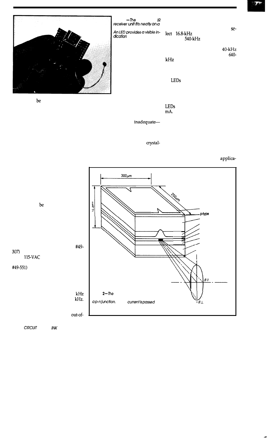
Photo 1
modulated
with crystal reference. The two-chip
circuit typically operates on 12 V but
small piece of perf board.
will tolerate 6-14-V supplies. To
of
when
the reiay is
a
modulation frequency
energized.
you use a
ceramic resonator
and the Q4 pin on the CD4024 binary
divider chip. To select a
modulation frequency you use a
ceramic resonator and the Q5
output pin. The resulting clock fre-
quency is used to switch the gate of a
power FET and six series-connected
IR
(the red LED is there just to
tell you something is happening).
With each diode dropping about
is too low to accurately sensed above
the background light levels.
Unbundling the transmitter and
receiver extends the usable range.
Since the receiver is tuned to a specific
modulation frequency, it makes sense
that any source of this frequency
would trigger the relay in the same
way as a reflected beam would. Fur-
ther, if this substitute source could be
collimated into a tight beam it could
actually be located hundreds of feet
from the receiver and still trigger the
relay if it were the right modulation
and sufficient intensity. When you
considerhowlittlelightactuallycomes
back from an internal LED reflecting
off something 20 feet away it is no
wonderthatsubstitutingamodulated
IR source makes a big difference. This
difference can translated two ways:
a bright detection point source allows
extended range for a given receiver
sensitivity, or it can increase the relia-
bility of detection at shorter distances
by improving the signal-to-noise ratio
with lower receiver sensitivity.
Radio Shack sells two off-the-shelf
IR beams sensors. One (model
is a stand-alone unit with an in-
ternal
power supply, buzzer,
and relay. The second unit (model
is smaller and requires an ex-
ternal 12-V supply. Interestingly,
while these units serve the same func-
tions and are sold by the same vendor,
they operate at different modulation
frequencies. The first one uses40
while the second operates at 16.8
My experiments indicated that
these two units are very selective and
don’t have a lot of tolerance for
42
CELLAR
band signals. Even a very bright IR
source only 400 Hz off frequency will
be ignored. Because they are so selec-
tive, simple RC or 555-type oscillator
circuits are generally
especially if the application involves
large ambient temperature swings.
The proper design for long-term op-
eration should incorporate a
controlled frequency reference.
Figure 1 and Photo 1 show a simple
high-power infrared LED modulator
1.7 V and the IRF530 having an on
resistance of about 0.18 ohms, the IR
are being pulsed with about 200
This is very bright and will work
in most ambient conditions.
LASERS: LIGHT SHOW OR
COMMUNICATION?
It’s one thing to be challenged, it’s
quite another to succeed. While the
circuitry just described might sound
adequate for virtually any
Al Electrode
Electrode
Substrate
Current Blocking Layer
Cladding Layer
Active Layer
Cladding Layer
Cap Layer
,
n-type Electrode
Figure
laser diode is a block of
semiconducting material containing
When
Radiation Pattern
through
the junction, energy is re-
leased as light and heat.
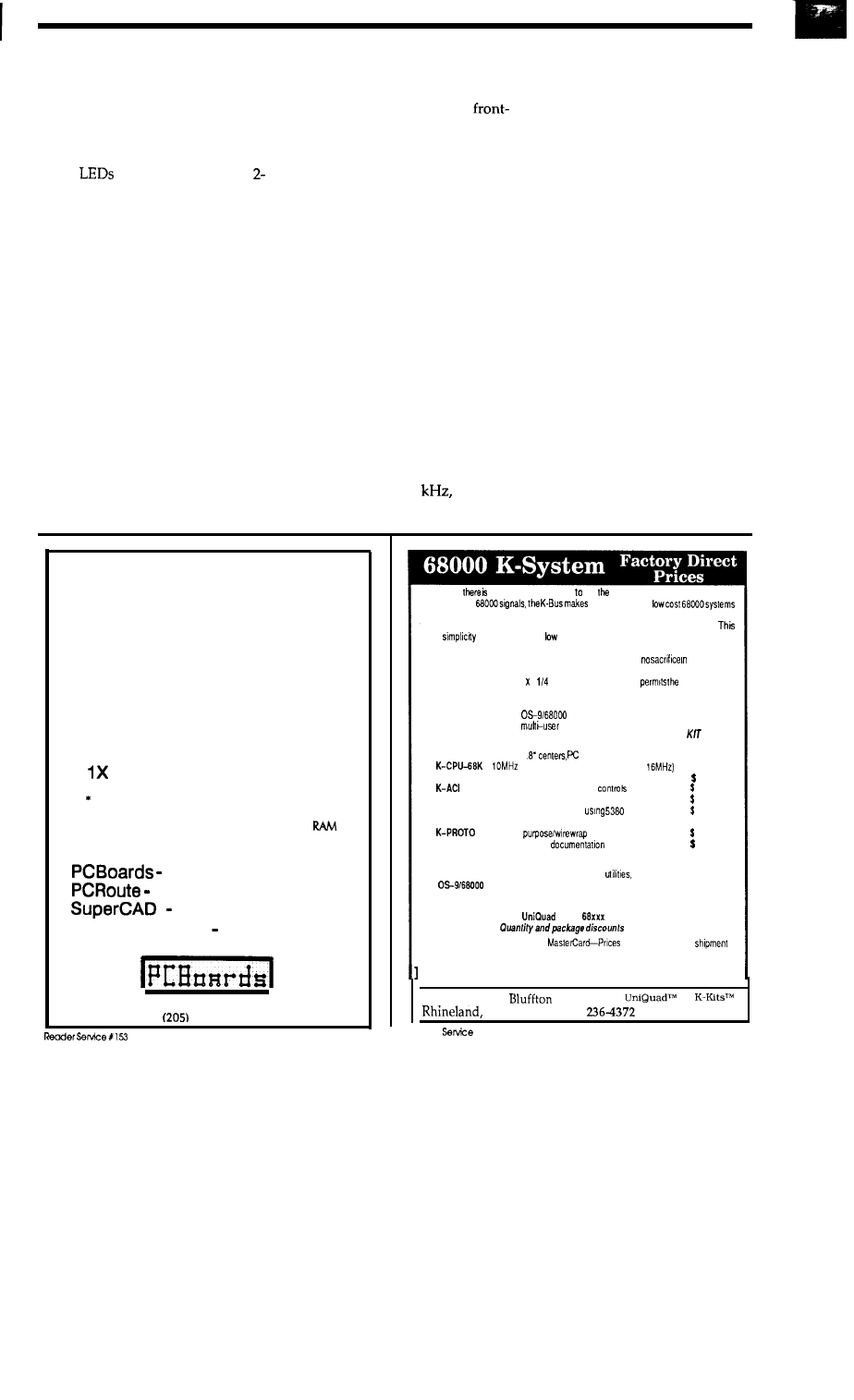
tion, the realities of signal-to-noise in
my specific outdoor application is a
bear. Out there every leaf, snow flake,
and rain drop becomes a potential
false-positive detection error.
Using the previous circuit only
solved part of the problem. Bundling
the six
together and adding a
pound, 4-inch-diameter lens provided
an error-free signal for the 15 feet across
one part of the driveway. Unfortu-
nately, I still had a one-hundred-foot
span to cover that seemed an insur-
mountable objective.
Rather than jack hammer the
pavement
installing pressure
transducers, or stake out a pit bull
with a walkie-talkie, I concluded that
the only high-powered light source
that could go the distance and stay
collimated would be a laser. Initially
I had rejected them because of the cost
and complexity of use, but I was get-
ting desperate. A simple experiment
convinced me that this was indeed the
answer.
Since I had done a previous article
on modulating a He-Ne laser, I had all
the necessary experimental hardware
at hand.
As dusk approached, I
mounted the laser on a tripod next to
the garage and aimed it at a
surface mirror about 100 feet away.
The mirror in turn reflected the beam
along
another
sensing
path, through a
kitchen window, onto the lens of the
receiver (considering that the envi-
ronment and weather played such a
role, if it could be detected through
the window then I wouldn’t have to
deal with heated enclosuresand other
weatherproofing headaches). I con-
nected a table lamp through the re-
ceiver relay so that I could monitor
results from outside.
Turning the laser on cast a faint
red spot on the mirror and window
pane but the laser still projected a
bright spot that covered the whole
receiver lens. Even after a distance of
about 150 feet the spot was only about
three inches in diameter. I turned on
the modulation oscillator and slowly
increased the input frequency to the
laser. As I passed 39.6
the table
lamp came on. Using my hand to
interrupt the beam, it shut off in re-
sponse. Success at last?
Well beyond dusk now, I walked
back toward the house to check the ar-
rangement once again. Satisfied that I
might have solved the problem at last,
I glanced over my shoulder toward
my handiwork. Egad! It looked like a
carnival light show! Red laser beams
projected all over the place.
The bright red beam extended
across the driveway from the laser to
the mirror. The mirror reflected from
its front surface, back surface, edges,
dust, scratches, you name it. It could
hardly have been more noticeable if I
had mounted a red flood light in place
of the mirror. Where the beam passed
through the kitchen window, the situ-
ation was repeated. The various re-
flected beams were much weaker but
in the darkness they were quite pro-
nounced and had the appearance of
multiple starbursts.
Well, it was obvious that this in-
trusion detector had a few bugs. The
laser had the proper intensity and
sufficient signal-to-noise ratio, but
P-C-B ARTWORK
MADE EASY !
Create Printed Circuit Artwork
on your IBM or Compatible
* MENU DRIVEN
* HELP SCREENS
* ADVANCED FEATURES
* EXTREMELY USER FRIENDLY
* 1X and 2X PRINTER ARTWORK
*
HP LaserJet ARTWORK
HP and HI PLOTTER DRIVER optional 49.00
REQUIREMENTS: IBM PC or Compatible, 384K
DOS 3.0 or later.
layout program 99.00
auto-router
99.00
schematic pgm. 99.00
D E M O 10.00
Call or write for more information
2110 14th Ave. South, Birmingham, AL 35205
933-l 122
Now
a bus that makes it easy use entire family of 66000 components.
Utilizing native
ilpossbletocreale
in a straightforward manner. The simplicity inherent the K-System concept allows the sys-
tem designer the ability to concentrate on meeting the demands of the applications.
same
combined with its
cost makes the K-System ideal for applications
ranging from personal use through educational and laboratory applications up to industrial
control and systems development. All of this is accomplished al
performance
or reliability.
The convenient size (4 5 inch) of the K-Bus boards
optimal division
of system functions thus simplifying system configuration. The motherboard incorporates
integral card guides and compatible power connectors which minimizes packaging require-
ments. Both SKDOS and
are fully supponed allowing efficient system
utilization in both single and
applications.
Boards currently in production:
A V A I L A B L E I N
F O R M
K-BUS
K-MEM
K-FDC
K-SCSI
K-DMA
K-xxx-BB
Software:
SKDOS
12 Slots,
type power connectors
$129.95
66000 CPU, 2 ROM sockets (12 or
$129.95
256K static RAM or 27256 type EPROMs (OK installed) 59.95
2 serial ports with full modem
(68661)
99.95
Floppy disk controller (up to four 5 t/4 drives)
99.95
Full SCSI implementation
chip
99.95
2 channel DMA controller using 68440 chip
$129.95
General
board
39.95
Bare board with
for above
39.95
Single user, editor, assembler,
BASIC
$150.00
Multi-user. editor, assembler, SCRED, utilities BASIC,
C, PASCAL. FORTRAN are available
$300.00
Inquire about our
line of
Single Board Computers.
available
Terms: Check, Money Order, Visa,
Include UPS ground
in
continental U.S.
Hazelwood Computer Systems
Highway 94 at
MO 65069
l
(314)
Reader
X127
A p r i l / M a y 1 9 9 0 4 3
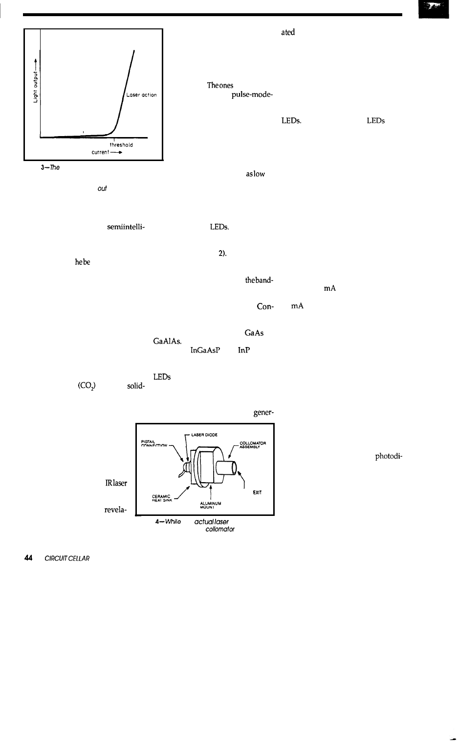
LED operation
Laser
Drive
Figure
laser
diode’s drive current must be
carefully regulated near the laser threshold so it is
high enough to be above the threshold, but low
enough to avoid burning
the diode.
using a visible laser was impossible.
What seemed barely visible in day-
light was now quite spectacular in
darkness. Certainly no
gent door-to-door salesman would
allow himself to be detected by a sys-
tem that he could merely step over or
around. Should
closely followed
by some eco-phreak protesting laser
irradiation of the neighborhood and
innocent children, I could also have a
bunch of crazy radicals on my hand. I
had to be more clandestine about such
activities. Invisibility was the only
answer.
INFRARED LASER DIODES
I had had more experience with
them. Laser diodes have been
around for years for use in fiber-
optic communications, but they
have been extraordinarily ex-
pensive and complicated to
modulate.
I had previ-
ously used were
only devices that were hardly
applicable.
Fortunately, im-
proved manufacturing tech-
niques and higher production
volumes have changed the situ-
ation entirely. With millions of
lasers in CD players and print-
ers, it’s possible to find continu-
ous-output devices for
as
$5 apiece from surplus houses.
The more cost-effective invisible
lasers emit in the infrared range. The
most common types of these are car-
bon dioxide gas
and LED
state lasers. CO, lasers tend to be a bit
large and on the powerful side. Of
course, if one’s intention is deterrence
as well as detection, setting fire
to a salesman’s sample case as
he passes through the beam will
certainly do that. All humor
aside, however, CO, lasers are
much too costly and dangerous
for anything less than high-heat
applications or starwars.
diodes are really the better way
to go.
Laser diodes are similar in struc-
ture to standard
The laser di-
ode is a block of semiconducting
material containing a p-n junction just
like an LED (Figure When current
passes through the junction, energy is
released as light and heat. The color of
theemitted light dependson
gap energies of the materials used,
and the amount of waste heat depends
on the conversion efficiency.
tinuousoutputdouble-heterojunction
laser diodes, typically used in CD
players, are made from
or
They radiate at 720 to 900
nm. New
and
lasers
emit in the range of 1150 to 1600 nm.
From a structural standpoint,
and laser diodes are very simi-
lar. The only important difference is
that in a laser diode two of the edge
faces (or facets)
are
cleaved
and coated
so that they reflect part of the
CONNECTION
This was not a new
DIODE DYNAMICS
tion, unfortunately. I would
have used a laser diode instead
Figure
the
diode is quite
of an IR LED in the first place if
small, the heat sink and
assembly are
necessary for proper operation.
LIGHT
light back into the semiconduc-
tor. The reflected light stimulates the
emission of other photons. The stimu-
lated emission also tends to produce
the strongest amplification at narrow
wavelengths rather than across a broad
range like an LED.
Of course, there is a price to be
paid for all this. Laser diodes operate
at much higher drive currents than
At low currents,
and
laser diodes behave the same. At
slightly higher currents, the laser di-
ode becomes a superluminescent di-
ode but does not have sufficient gain
to produce laser oscillation. Only
when the operating current is equal to
or greater than the laser diode’s
“threshold current” will the diode
operate as a laser. Figure 3 shows a
typical threshold curve.
This threshold curve is very im-
portant to laser diode operation and
figures prominently in driver circuit
designs. The threshold point of a laser
diode is a dynamic value which de-
pends greatly on case temperature.
Special care should especially be taken
at low temperatures. A laser diode
that takes 80
to operate when the
temperature is 60°C might only take
50
at 0°C for the same light out-
put. Unless the current is reduced as
the temperature decreases, excessive
drive current will burn up the diode.
The lifetime of a laser diode de-
creases sharply with higher operating
temperature and output power. In-
creasing the operating temperature
causes threshold current to rise and
efficiency to drop. The lost efficiency
creates more heat again. Left un-
checked, such a condition can cause
thermal runaway of the laser diode.
To facilitate proper operation,
laser diodes incorporate an integral
photodiode (usually mounted on the
rear facet) which directly monitors
the light output. Using this
ode in a closed-loop controller allows
a system to set a specific light inten-
sity regardless of ambient tempera-
ture. In combination with a simple
heat sink to remove excess heat dur-
ing operation, virtually all worry of
thermal runaway is eliminated.
Once you’ve got the diode run-
ning you might think that a tight beam
INK
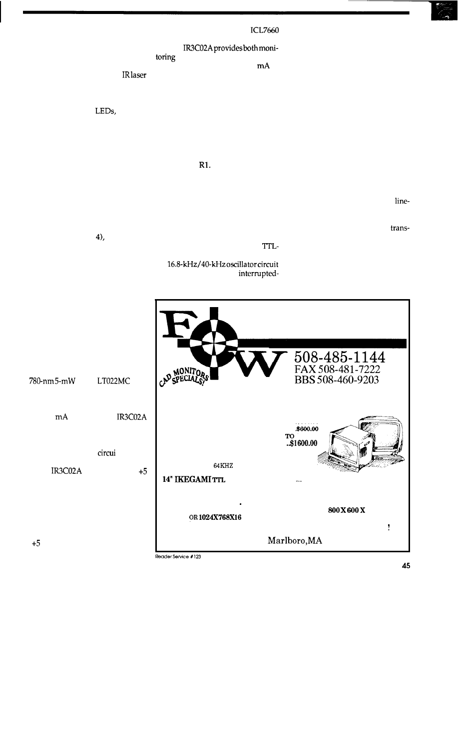
of light is automatically emitted from
the laser’s quartz window and you
can project a spot on the wall, right?
Guess again. Like an LED, the beam
spreads out in an elliptical pattern
from the diode. For the typical
diode, the beam spreads out at a 35”
angle perpendicular to the junction
and 10” in the plane of the junction.
Just like regular
laser di-
odes rely on external optics and hous-
ings to redirect the light. Laser diodes
generally use stacked lenses called a
collimator to tighten the beam into
circular form and concentrate the
energy. In my experience, trying to
use a laser diode without a collimator
is like running a car without gas: it has
a lot of potential but goes nowhere.
When you
purchasea laserdiodemake
sure it has a collimator if your inten-
tion is to have a laser “beam.” Like the
laser diode used in my prototype
demonstrates (Figure this collima-
tor and diode combination need not
be particularly large.
MODULATING LASER DIODES
Diode lasers require no warm up
and can be modulated directly by
varying the drive current. However,
whatever the modulation technique,
the laser’s specified operating enve-
lope must be maintained below its
maximum operating limits.
Figure 5 is the schematic of the
closed-loop laser diode modulator
pictured in Photo 2. The laser diode is
a
Sharp
laser
diode with attached collimator which
I bought from Meredith Instruments
for $15. Its threshold current is nomi-
nally 50
at 25°C. The
chip is a special closed-loop laser diode
controller chip made by Sharp. It
includes all the current averaging,
driver, and comparator
ts needed
to operate and protect a laser diode.
The
chip operates on
V and -5 V. Because my particular
control system uses a common 12-V
bus to power remote peripherals, I
added power supply circuitry to the
modulator that allows it to operate
from a single 9-24-V supply input.
This supply
voltage
is
regulated down
to V with a 7805 three-terminal reg-
ulator and inverted with an
DC-to-DC converter to produce -5 V.
The
and feedback control to the laser
diode and provides up to 170
of
drive current. The laser diode is con-
nected between pins 1 and 2 with a
series current-limiting resistor. The
laser’s photodiode monitor is con-
nected between pins 2 and 3.
When current is turned on, the
controller chip ramps the power to the
laser diode. As power is applied, the
laser’s output is compared to a preset
maximum power level determined by
the settingof
If theoutputexceeds
the setting, the chip automatically
lowers the current to compensate.
External modulation is applied
through a separate transistor which
provides additional drive current to
the laser. The collector resistor limits
this additional drive current to be
within protectable limits. The base of
the transistor connects to any
level modulation source. You can use
the
from Figure 1 to make an
beam sensor or you can send any form
of digital data.
SEEING IS BELIEVING
The good news about using a
modulated infrared laser as an inter-
rupted beam sensor is that you can
use it for hundreds of feet. The bad
news is that it is impossible to aim
without considerable effort.
Twenty-foot reflected-beam sen-
sors project a very large irradiation
pattern. A little trial and error holding
the reflector until you happen upon
the right “spot” to trigger the beam is
a relatively easy task. At 20 feet, simple
eyeballalignment techniquesarequite
adequate.
Using an infrared laser at a dis-
tance of 200 feet is quite another mat-
ter. Commercial units usually incor-
porate sighting scopes for direct
of-sight alignment. Like sighting a
hunting rifle, one simply sets the re-
ceiver in the crosshairs of the
mitter’sscopeand tumson the switch.
Unfortunately, once we add any kind
of an angled reflector into the laser
beam’s path, visible alignment is com-
plicated by an order of magnitude.
Still, like the visible He-Ne laser,
there is no real substitute for seeing
COMMUNICATIONS
LOWBUDGETSPECIALS
19” COLOR SUPER VGA
MONITOR
LIKE NEW 6 MONTH WARRANTY . . . . . . . . . . . . . . . . . . $800.66
USED 3 MONTH WARRANTY . . . . . . . . . . . . . . . . . . . . . . . . . . .
USED WITHOUT CASE . . . . . . . . . . . . . . . . . . . . . . $300
$660.06
19” COLOR SONY 1280 X 1024 . . .
THESE SONY TRINITRONS HAVE A FULL 6 MONTH
WARRANTY PARTS AND LABOR.LIMITED QUANITY
16” IKEGAMI
1280X1024 NEW . . . . . . . . $899.00
16” PANISONIC
64KHZ USED . $599.00
VGA CHASIS . . . . . . . . . . . . $249.00
NEW WITH 1 YEAR WARRANTY
19” PHILLIPS 1024X800 48 KHZ GRAY SCALE . . . . . . . . . . . . . . . . . . $350.00
NEW 1 YEAR WARRANTY MAY BE ORDERED FOR VGA AT NO EXTRA CHARGE.
WHEN USED IN VGA MODE THE MONITOR WILL RUN
256 GRAY
SCALE
GRAY SCALE ONLY
CALL US ABOUT OUR LARGE VARIETY OF GRAPHIC CARDS
194 Main ST.
01752
April/May 1990
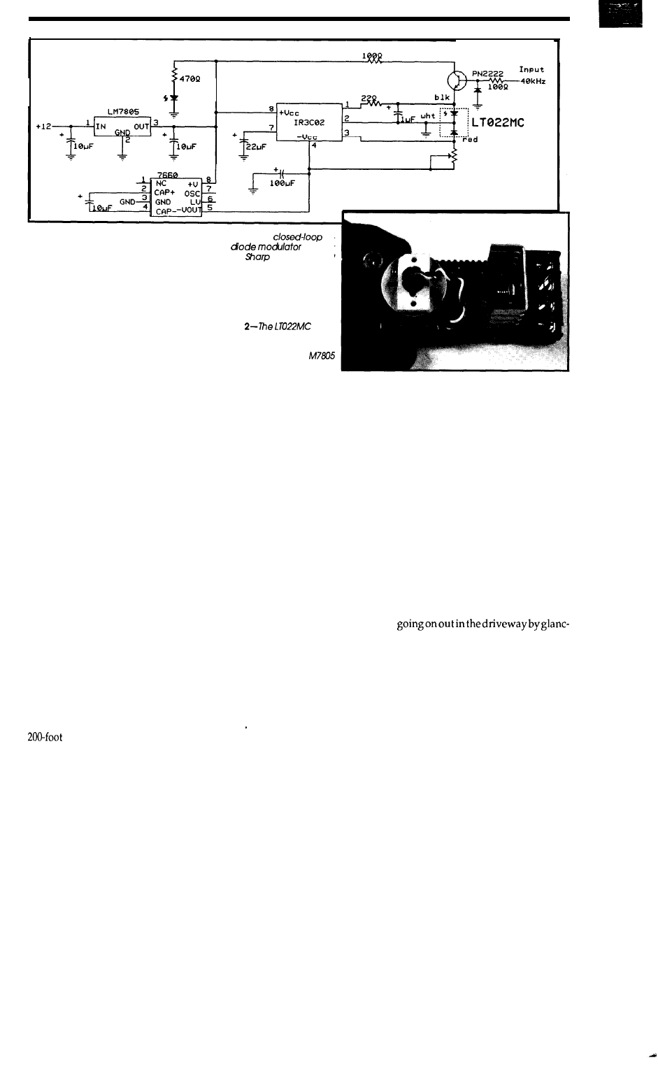
Power
Modulated
where the beam is actually going. Are
we receiving the true incident beam or
a secondary reflection? Is the receiver
set in the center of the projected spot
or at the edge? Just how bright of a
signal is this after bouncing off two
reflectors anyway? How do I know I
don’thavesomedangerousreflections
pointed directly at my eyes while I’m
working on this? Questions like this
can only be answered if we actually
“see” the infrared laser beam.
While infrared radiation is invis-
ible to the humaneye,itisquitevisible
to “electronic eyes.” A video camera
or camcorder which incorporates a
CCD (charge-coupled-device) video
sensing element “sees” infrared light
the same as visible light. If you aim a
CCD camera at a blank wall and point
the average hand-held IR remote
control at it, it will appear like you
have a flashlight aimed at the wall. In
fact, these invisible sources of light
look surprisingly bright once you can
see them!
The correct and safe way to ex-
periment with and align an IR laser
device is to do it entirely with a CCD
camera. While wearing IR safety
glasses, view the operating laser on a
video monitor. That way you can see
exactly where it’s going and measure
relative intensity as well.
Of course, this can all appear a bit
Rube Goldberg to the neighbors. In
the dark of night I loaded the video
monitor, camera, tools, and assorted
test gear into a wheel barrow with a
extension cord. I attached the
transmitter to the side of the garage
and pointed it toward a piece of white
46
CIRCUIT CELLAR INK
Figure 5-The
la-
ser
circuit
uses a
chip designed
specifically for the purpose.
Photo
laser
diode can be seen on the left
side
of the prototype of the
circuit in Figure 5. The L
is attached to the heat sink.
posterboard about 100 feet away.
Using the CCD camera, I easily cen-
tered the three-inch spot on the mir-
ror. Using the cardboard again al-
lowed me to find and position the
beam at a convenient location on the
side of a post. I centered the receiver
in the beam pattern and the relay in-
stantly pulled in. Success!
OUT OF ISOLATION
Unfortunately, a good design
tends to multiply. One little laser on
thecomerofthegaragehasbeenjoined
by one across the front deck and one
between the house and small garage.
Next, I suppose1 have to add one from
the small garage to the big garage, one
across the rear deck and, I suppose,
across the other driveway entrance
(What? I failed to mention that one?).
Monitoring the perimeter could get a
little out of hand. Eventually I could
have this giant web of infrared sens-
ing energy encircling the whole
place..
Enough! See what happens when
you make a little LED flasher that
works!
Inactuality, thisinterrupted-beam
sensor design is only part of an inte-
grated network of environmental
monitoring and control. I view these
sensors as positive verification that
other more esoteric devices are actu-
ally working correctly. It is quite true
that a web of IR beams is a total solu-
tion in itself but this involves a lot of
hardwiring and physical placement
of sensors. Considering that the latter
is done primarily with a posthole
digger, I continue to look for less
strenuous sensing alternatives.
being down in the Circuit Cellar
is no longer like being in a hole (actu-
ally, this cellar is better than most
people’slivingrooms). Icanseewhat’s
ing at a video monitor with automatic
camera switching (see
C
IRCUIT
C
ELLAR
INK
issues 1 and 2 for the design of
this video multiplexer). My next de-
sign objective is to totally dispense
with the perimeter sensors and use a
processor with the cameras to directly
do motion sensing and pattern recog-
nition.
Yes, I know that such systems
supposedly exist. I already have a
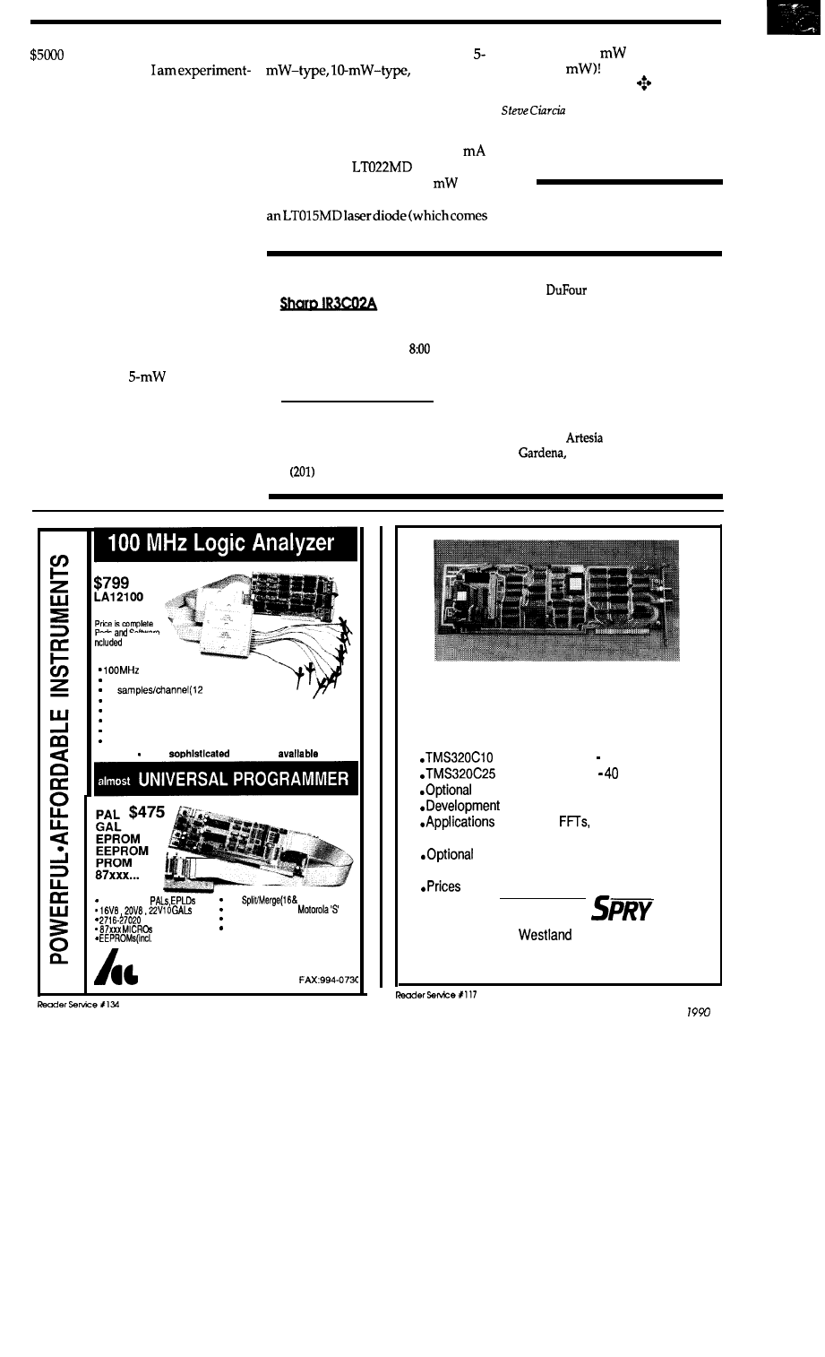
Sony video
motion detecting
systeminstalled that
ing with, and
there are
many PC-based
units offered as well. Unfortunately,
like the IR beam sensors I just finished
discussing, these units won’t work
outside either. The dynamics of out-
side lighting causes too many errors.
So,
I have an infrared laser/mag-
netic loop sensor that tells me that
something is there. The next objective
is for the control system to decide who
or what it is. Stay tuned; it’s only a
matter of time!
CAUTION
If you choose to experiment with
lasers, especially invisible ones, I can’t
caution you enough about safety.
Admittedly, the
unit I chose to
use poses little hazard unless placed
against your eyeball, but I approached
the whole technology with respect.
Since many of the laser diodes avail-
able to experimenters come via the
surplus market, they
often
come with-
out complete manufacturer specs or
guarantees. In fact, most are sold as
and so on,
with
virtually
no
real specifications or
ideas of what they may be using as
substitute parts. At the very worst, it’s
quite possible to end up with a wolf in
sheep’s clothing. Applying 85
current to an
laser diode
typically produces about 3
out-
put. If you apply the same current to
in the same physical package) it pro-
duces about 30
(and can go as
high as 50
Who knows what’s
in the bag? Be careful!
(pronounced “see-ARE-see-ah”)
is an electronics engineer and computer con-
sultant with experience in process control,
digital design, and product development.
IRS
210 Very Useful
2 11 Moderately Useful
2 12 Not Useful
SOURCES
Available prepaid from Marshall
Industries. Call (800) 522-0084
between 9:00
A
.
M
.
and
P.M.
EST for pricing and delivery.
Lasers and laser diodes
Sharp Corp.
Electronic Components Division
Sharp Plaza
Mahwah, NJ 07430
529-8757
Gott Electronics
2227
Ave.
Redondo Beach, CA 90278
(213) 370-6287
Meredith Instruments
6403 N. 59th Ave.
Glendale, AZ 85301
(602) 934-9387
Timeline, Inc.
1490 W.
Blvd.
CA 90247
(800) 872-8878
(213) 217-8912
Pods
Software
sampling rate(12 channel)
24 Channels(50 MHz), Timing and state
2K
Channel mode)
24 Bit trigger word
TTL threshold level
Internal and External Clocks
Menu driven software
FREE software updates on BBS
More
units also
20 and 24 pin
Byte
32 bit)
JEDEC, INTEL HEX,
files
EPROMs
Dallas NVS RAM programming
PC/XT/AT COMPATIBLE
6 pin serial)
l
FREE software updates on BBS
Call-(201)994-6669
Link Computer Graphics, Inc.
4 Sparrow Dr., Livingston, NJ 07039
PC BASED DIGITAL SIGNAL
PROCESSING AND
DATA
ACQUISITION
based Model 10 25 Mhz
based Model
25
Mhz
12 Bit, 110 Khz A/D and D/A
Software, including Debugger
Software:
Spectral Analysis
Program
Continuous, No Gap sampling to/ from
disk at high rates
start at $650.00
D
ALANCO
89
Avenue
Rochester, NY 14618
(716) 473-3610
A p r i l / M a y
4 7
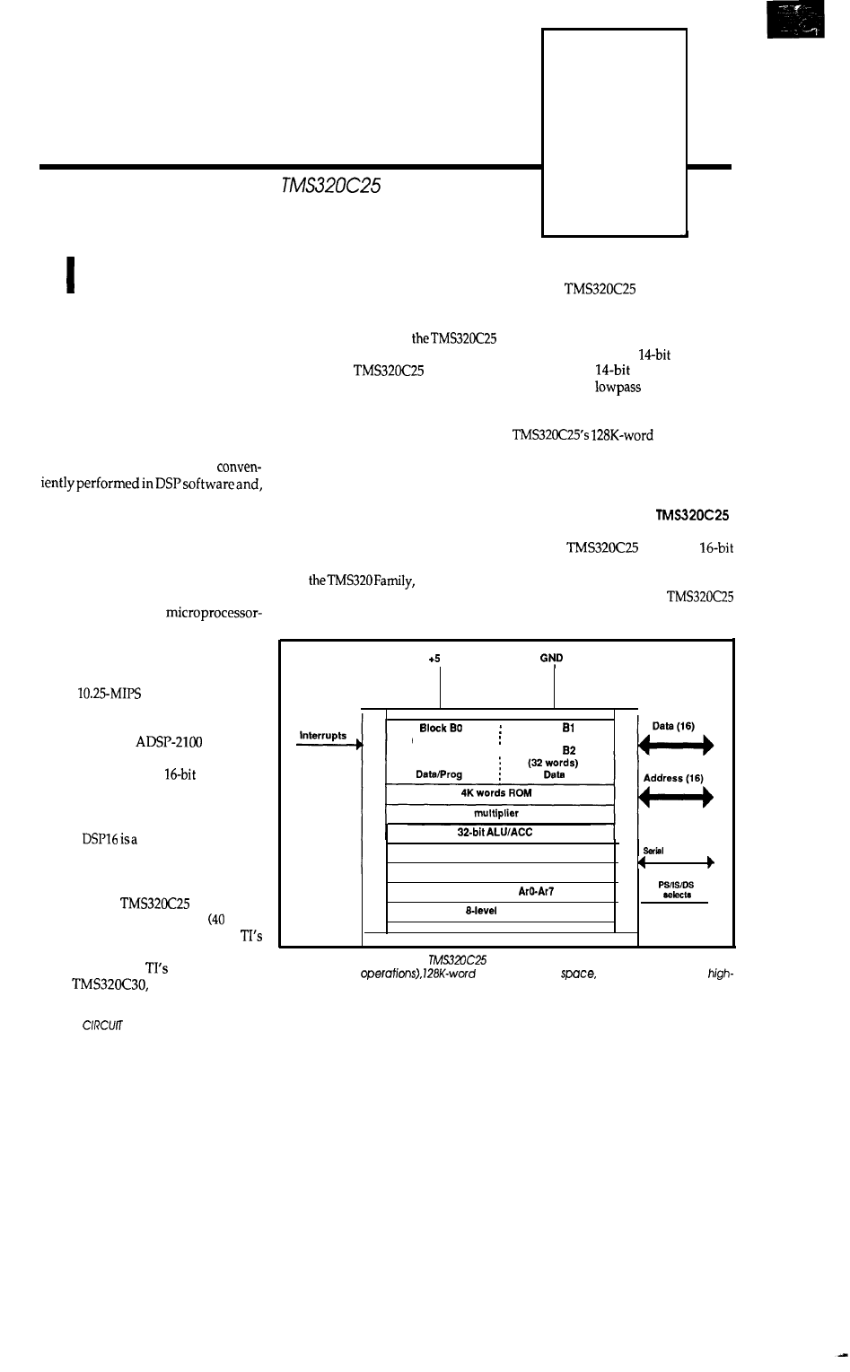
Digital Signal Processing
PART 2
Dean McConnell
DSP Applications with the
n the previous article, we dis-
cussed fundamental Digital Signal
Processing concepts. Concepts were
illustrated with BASIC language rou-
tines running on a PC/XT with EGA
graphics. These demonstration pro-
grams implemented DSP functions
such as digital filtering, correlation,
and Fourier transforms. We also
showed that common analog func-
tions (comparators, peak clippers,
rectifiers, and so on) could be
thus, replace analog circuit compo-
nents.
For real-time digital signal proc-
essing, however, a PC alone is not
capable of performing the high-speed
sum-of-products operation required
by digital filters and correlation.
Many excellent
like DSP chips have been unveiled by
various manufacturers such as Texas
Instruments, Analog Devices, AT&T,
and Motorola. The Motorola 56001, a
24-bit
DSP chip which has
two separate X and Y data memories,
is featured within Steve Jobs’ NeXT
computer. The
DSP chip
(manufactured by Analog Devices)
provides 10 MIPS of
processing
power and an assembly language in-
struction set which is almost like an
HOL (high-order language). The
AT&T
fixed-point DSP chip
(like all of the previously mentioned
processors) while the DSP32 is a 32-bit
floating-point DSP chip. The Texas
Instruments
DSP chip is
an enhanced CMOS version MHz)
of the popular TMS32020 chip,
second-generation member of the
TMS320 family.
latest offering,
the
is a 32-bit, 33-
4a
CELLAR INK
MFLOPS floating-point DSP which
Out of all the possible DSP chips
recently went into full production.
on the market, I chose
as the basis of a PC-hosted DSP card
design. The
offered me
the following benefits:
The TMS32010, (the first genera-
tion of the TMS320 family) is source
code compatible with newer genera-
tions of the TMS320 family, which
allowed me to reuse my existing
TMS32010 routines.
TI provides extensive support via
hotline, newsletters, BBS, and pub-
lished applications articles and re-
ports. An excellent reference is “Digi-
tal Signal Processing Applications
with
Vol. I” (avail-
able from Prentice Hall, Englewood
Cliffs, NJ).
band DSP experiments (10 MIPS). It is
compatible with the TLC32044 Ana-
The
provides
log Interface Chip, a
D/A con-
more
verter and a
A/D converter
than enough performance for
(with built-in
antialiasing fil-
ter) which interfaces with the C25 via
voice
a high-speed serial port.
The
totaladdress
space provides plenty of room for user
applications, and its price is moderate
as far as DSP chips go (about $80).
AN OVERVIEW OF THE
The
DSP is a
fixed-point microprocessor optimized
for digital signal processing opera-
tions. Key features of the
include:
v
Interrupts
Block
(256 words)
(256 words)
Block
shifters
timer
auxiliary registers
stack
Interface
-
-
-
Figure
l-Key features of the
include on-board high-speed RAM (used in
digital filtering
data/program
and a synchronous
speed serial port.
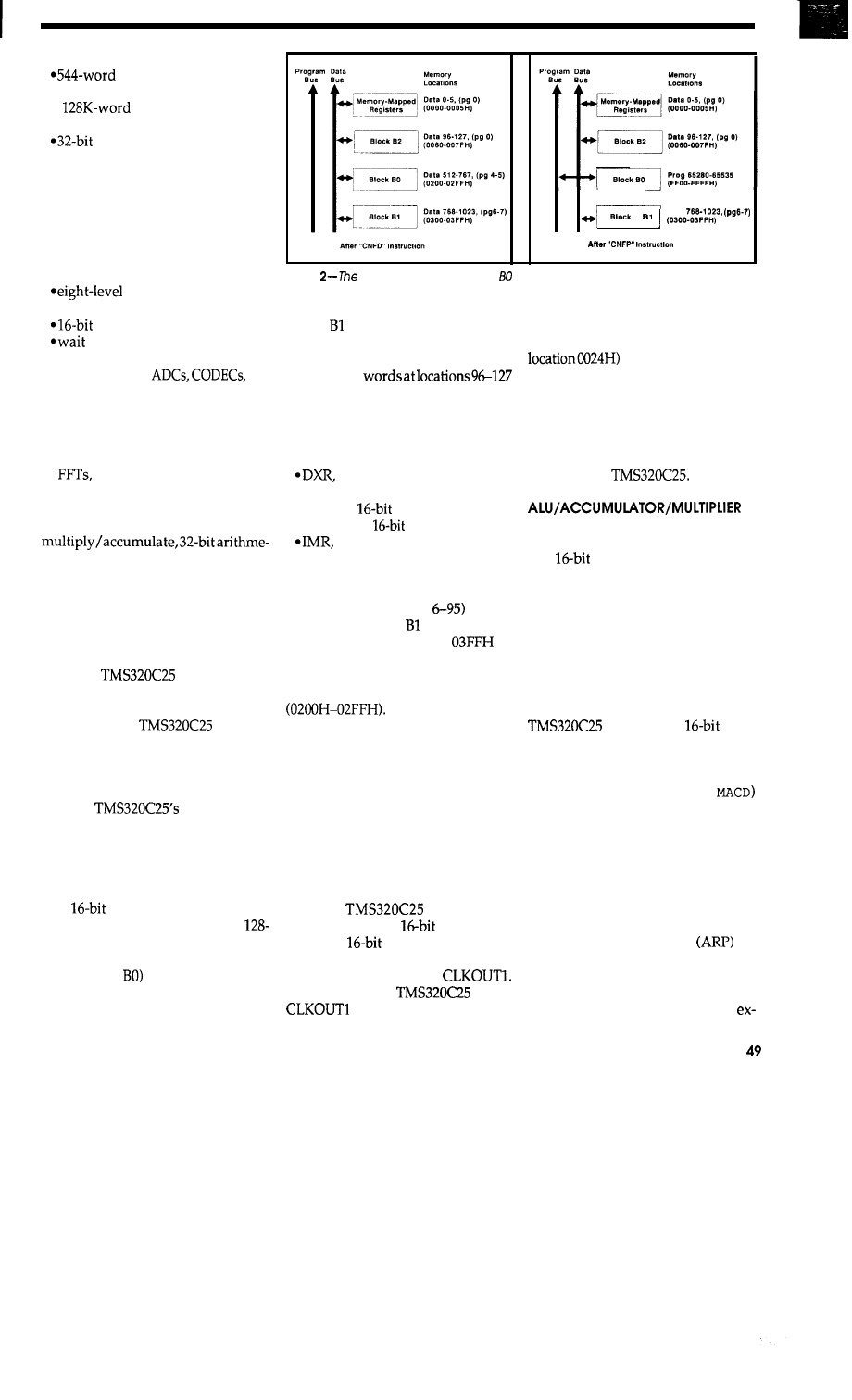
l
lOO-ns instruction cycle
programmable on-chip
data RAM
l
total data/program
memory space
ALU/accumulator
*16x16-bit parallelmultiplier with
32-bit product
*repeat instructions for efficient
memory and processor use
l
block moves for data/program
management
eon-chip timer
*eight auxiliary registers
hardware stack
*sixteen input and output ports
parallel shifter
states for slower off-chip de-
vices
l
serial port for
or
high-speed communications
*global data memory interface
*source code compatibility with
TMS32010, first-generation DSP
*instructions for adaptive filtering,
and extended-precision
arithmetic
*CMOS technology
Features such as single-cycle
tic unit, large auxiliary register file,
and fast on-chip RAM, make the de-
vice a natural choice for digital signal
processing applications. However,
due to the large address spaces, mul-
tiple interrupts, wait states, timer,
serial port, and multiprocessor inter-
face, the
is also a good
choice for high-speed general-purpose
micro designs. Let’s examine the key
elements of the
architec-
ture, as shown in Figure 1.
MEMORY MAP
The
memory map
hasitsprogrammemoryseparatefrom
data memory, thus implementing a
standard Harvard architecture. A to-
tal of 64K words of program memory,
64K words of data memory, and six-
teen
I/O ports are addressable.
Data memory is partitioned into
word pages. There are 544 words of
on-chip O-wait-state RAM, 256 of
which (Block
can be configured as
data memory or program memory,
selectable under software control.
I
_
_
_
D a t a
Figure
on-board 256-word block RAM can appear in the data map or written
program space through the software instructions
CNFD and CNFP.
Blocks and B2, the remaining 288
words of on-chip RAM, are always
configured as data memory. Block B2
consistsof 32
in page 0. The first five words are re-
served for on-chip memory-mapped
registers, and include:
l
DRR, the serial port receive regis-
ter
the serial port transmit reg-
ister
*TIM, the
timer register
l
PRD, the
period register
the interrupt mask register
*GREG, the global memory alloca-
tion register.
The remaining memory locations
of Block B2 (locations
are re-
served by TI. Block resides in data
memory from 0300H to
or
pages 6-7. Block BO, when configured
as data RAM (via the
CNFD
instruc-
tion), a p p e a r s i n p a g e s 4 - 5
When configured as
program memory (via the
CNFP
in-
struction), Block BO appears at
FFOOH-FFFFH in program memory
space (see Figure 2). The
on-chip
RAM
is used in conjunction with special
multiply/accumulate instructions to
perform the convolution operation
required by digital filtering.
ON-CHIP TIMER
The
provides a
memory-mapped
timer regis-
ter and a
period register. The
timer is a continuously clocked down
counter which is fed by
For a 40-MHz
DSP,
is 10 MHz. The period reg-
ister, PRD, holds the starting count for
the timer. A timer interrupt (vector
occurs when the count
goes to zero. The timer is reloaded
with the PRD value after a decrement
to zero. By programming the PRD
register from 1 to 65,535, a timer inter-
rupt, TINT, can be generated at inter-
vals ranging from 200 ns to 6.5536 ms
on a 40-MHz
The 32-bit accumulator is split into
two
segmentsforstorageindata
memory: ACCH (high 16 bits) and
ACCL (low 16 bits). The
SACL
dma
instruction stores the low accumula-
tor in the designated data memory
address while the
SACH
dma
instruc-
tion stores the high accumulator in
datamemory. Shiftersattheoutputof
the accumulator allow a left shift of
from zero to seven bit positions. The
utilizesa 16 x
two’s
complement multiplier which can
compute a 32-bit product in a single
machine cycle. Two multiply/accu-
mulate instructions
(
MA
C
and
provide the basis for sums-of-prod-
ucts operations used in filtering.
AUXILIARY REGISTERS
Eight auxiliary registers are used
for indirect addressing of data mem-
ory or for temporary data storage. The
auxiliary register pointer
se-
lects one of the eight auxiliary regis-
ters. Subsequent indirect addressing
instructions will use the auxiliary
register pointed to by ARP. For
April/May 1990
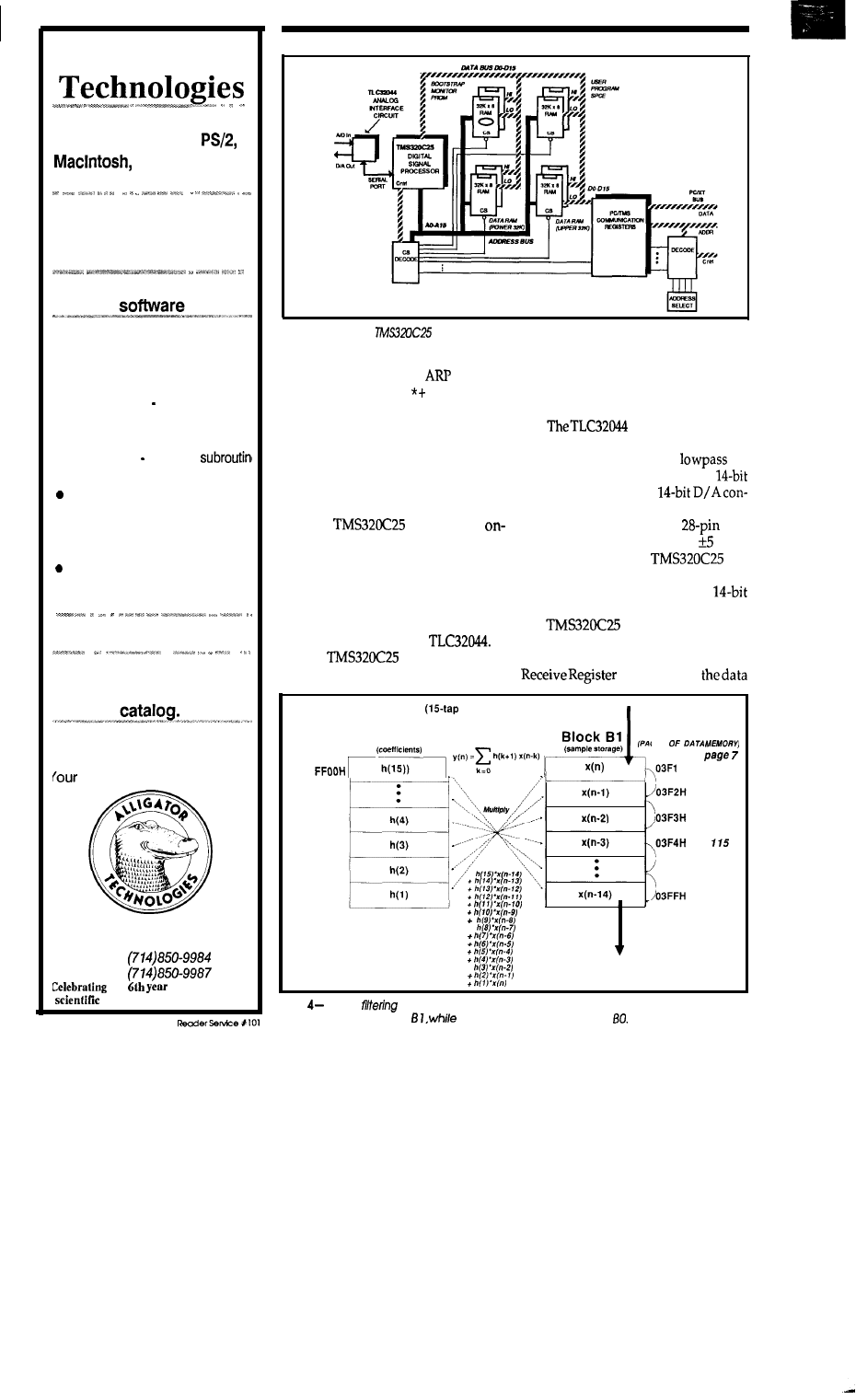
Alligator
High Performance interface
cards for the PC,
VAX, Sun, and
Apollo
l
A/D and D/A
Data Acquisition
l
Video Image Capture
l
Array Processing
l
IEEE 488
Powerful DSP and FFT
l
Menu driven and Subroutine
Figure
3-A typical
system design incorporates EPROM, RAM, and a TLC3204
libraries
for analog interfacing.
l
Data Acquisition and control
l
Extended analysis with Fourier
Perspective II Menu driven
advanced DSP
l
Prime
Factor FFT for
1
or
2
dimensions Callable
library
Extensive Image Processing
software
TLC32044 ANALOG INTERFACE
CIRCUIT
ample,
if the contents of
is 2, then
theinstruction
SACL
will store the
lower 16 bits of the accumulator in the
data memory address pointed to by
AR2 followed by an incrementing of
the AR2 auxiliary register.
SERIAL PORT
l
Publication Quality Scientific
Graphics software
Compilers and general
programming tools
l
Books and Technical
support
All at Affordable Prices
OEM’s
ask about our quantity pricing.
CALL, WRITE, or FAX for
your copy of our latest
The
includes an
chip full-duplex synchronous serial
port capable of operation to 5 MHz.
Uses of the serial port can include
high-speed synchronous data links,
interprocessor communication, and
connection to serial interface A/D con-
verter chips such as the
A
typical
design is shown
in Figure 3.
AIC (Analog Inter-
face Circuit) simplifies the task of
providing an antialiasing
fil-
ter, a sample-and-hold circuit, a
A/D converter, and a
verter. All of the AIC functions are
packaged within a single
DIP
or an LCC which runs off of volts
and connects to the
via
the 6-line serial port interface. When
an A/D sample is ready, the
sample is transmitted from the AIC to
the
causing a serial re-
ceive interrupt, RINT. The received
word is then read through the Data
(location0 in
FIR Filter Example)
New Samples
Please
tell us about your application. Our
staff of experts will provide you with the
best solution for your computing needs.
satisfaction is GUARANTEED!
P . O . B o x 9 7 0 6
Fountain Valley, CA 92708
V o i c e :
F a x :
our
of service to lhe
and engineering community.
Block BO
PROGRAM MEMORY)
N-l
Block
(PAGE 7
H
112
713
FFOBH
114
FFOCH
FFODH
FFOEH
+
Old
Samples
127
+
Figure
Digital
is made easy with the RPTK and MACD instructions.
Input
samples
are
p/aced
in block
coefficients are placed in Mock
5 0
CIRCUIT CELLAR INK
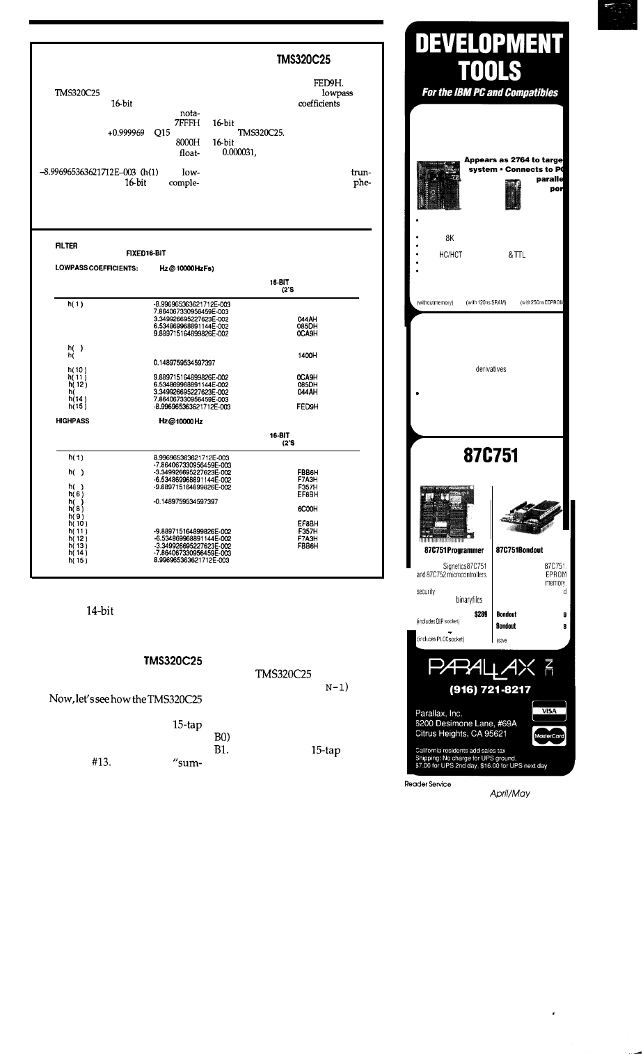
FIXED 16-BIT FRACTIONAL ARITHMETIC FOR THE
The
first step for implementation on
the
is to convert the floating-
two’s complemented to get
Shown
in the tables below are the
and
point numbers to a
two’scomplement
highpassfloating-point
from
the
representation. In two’s complement
tion, the largest positive number is
first article’s FIR filter examples and their
(which represents
in
format)
two’s complement counterparts used
and the most negative number is
by the
It is worth noting that
numbers have a minimum resolution
(which represents -1).
To
convert a
of
so we must round
any floating-
ing-point coefficient, for example
point coefficient to thenearest millionths.
in the
In very high-precision digital filters,
pass filter example), to
two’s
ment Q15 representation, we multiply by
cation of coefficients leads to Gibb’s
the maximum value available in 15 bits
nomenon, a “rippling” effect seen in the
(32,768). The resultant product, -294.8, is
stop band of the frequency response.
COEFFICIENTS
FLOATING-POINT AND
REPRESENTATION
(312.5
COEFFICIENT
FLOATING-POINT
NUMBER
VALUE
h ( 2 )
h ( 3 )
h ( 4 )
h ( 5 )
h ( 6 )
0.1295655647516251
7
0.1499759534597397
6)
0.15625
h(S)
0.1265655647516251
13)
COEFFICIENTS: (1250
Fs)
REPRESENTATION
COMPLEMENT)
FEDSH
0102H
1075H
1312H
1312H
1075H
0102H
COEFFICIENT
NUMBER
h ( 2 )
3
h ( 4 )
5
7
FLOATING-POINT
VALUE
-0.1265655647516251
0.64375
-0.1469759534597397
-0.1295655647516251
REPRESENTATION
COMPLEMENT)
0127H
FEFEH
ECEEH
ECEEH
FEFEH
0127H
memory map). To output to the DAC,
the desired
code is written to
data memory location 1 of page 0,
DXR, the serial port transmit register.
FILTERING WITH THE
DESIGN
can be programmed to perform real-
time digital filtering. Recall the
Finite Impulse Response (FIR) filter
from Part 1 of this article, in C
IRCUIT
C
ELLAR
INK
It required a
of-products” operation of the current
and 14 most recent past input samples
multiplied by 15 special coefficients
(each sum-of-products operation was
required with each new sample in-
put).
The
provides a re-
peat instruction
(
RPTK
which,
when coupled with a
MACD
instruc-
tion, performs a looped sum of prod-
ucts of coefficients (placed in Block
with data samples stored in Block
In the case of the
filter, the
argument to the
RPTK
instruction
2764
ROM EMULATOR
Plugs into target ROM socket and connects to PC
parallel port via modular telephone cable
Accepts x 8 SRAM or EEPROM (non-volatile)
I-state reset restarts target after downloading
Uses
logic for CMOS
compatibility
Loads Intel Hex, Motorola S, hex, and binary files
Command line software can be run from batch
files for automatic downloading after assembly
$139
$149
$159
8051 .
FAMILYASSEMBLER
l
Works on all 8051
l
Supports standard Intel syntax
l
Allows local labels and include files
Labels may be up to 32 characters
l
Generates assembly listings
l
Outputs Intel Hex
$ 5 9
Quick
l
Dependable
l
Clean Operation
DEVELOPMENT TOOLS
Board
Programs
“Mini-ICE” for the
Provides external
Handles EPROM, key, and
socket for program
bits. Loads Intel Hex,
Very useful when combine
ASCII hex, and
with ROM emulator
Programmer-DIP
Programmer PLCC
$329
Board
$23
Board and
$35
2164 ROM Emulator
$20)
X151
1990
5 1
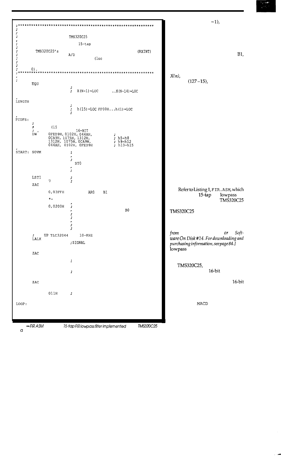
FINITE IMPULSE RESPONSE FILTER PROGRAM
For the
Digital Signal Processor
This program implements a
FIR Low-Pass filter. It
assumes that a TLC32044 Analog Interface Circuit is connected
to the
serial port.
A receive interrupt
occurs with every new
sample and is read through the
receive serial port register,
DRR
0 of data page 0).
Outputs to the D/A converter are performed through writes to
the serial data transmit register,
DXR (location 1 of data
page
PAGE 7 VARIABLES
XN
113
; STARTING LOCATION IN PAGE 7 WHERE
INPUT SAMPLES ARE STORED
114 .
127
YN
EQU
112
E
Q U
14
BOCOFS EQU
OFFOOH
BEGINNING OF BLOCK BO FILTER COEFF.
FFOEH
TMPO
EQU
112
used for temporary storage
FIR FILTER COEFF. FOR A 0.03125 Fs Low-Pass Filter
N = 15
taps)
015 FORMAT (FIXED
TWO'S COMPLEMENT)
085DH
hl-h4
DW
1400H
DW
085DH
DW
LDPK
LALK
SACL
LST
LALK
SACL
LDPK
LARP
LRLK
RPTK
SACL
CNFD
LRLK
RPTK
BLKP
CNFP
LDPK
LACK
SACL
EINT
0
OEOOH
TMPO ;
TMPO
03FOH
TMPO ;
TMPO
0
;
LENGTH ;
SET OVERFLOW (SATURATION) MODE
SELECT PAGE 0
INITIALIZE
TO
OEOOH
INITIALIZE
ST1 TO
03FOH
SELECT PAGE 7
POINT
TO
CLEAR INPUT BUFFER
LENGTH .
FCOFS,*+
0
020H
IMR
MAKE BLOCK BO DATA RAM
POINT TO BO DATA RAM ADDRESS
READ COEFFICIENTS INTO
LOAD FILTER COEFFICIENTS
NOW, CONFIGURE BO AS PROGRAM MEMORY
SELECT DATA PAGE 0
ALLOW ONLY TXINT
STORE IN INTERRUPT MASK REGISTER
SE
T
TO
A
SAMPLING
RATE
3
SACL
LALK
IDLE
EINT
IDLE
EINT
LALK
SACL
LALK
DXR
SECONDARY COM
32028
; set Fs TO 10280 HZ
; WAIT HERE UNTIL TXINT
WAIT HERE UNTIL TXINT
3
DXR
SIGNAL SECONDARY COM
1400H
; 16638
; WAIT HERE UNTIL TXINT
IDLE
IDLE
LACK
SACL
EINT
B
TINT:
SACL
EINT
RET
IMR
LOOP
DXR
; WAIT HERE UNTIL TXINT
ENABLE RXINT ONLY
; STORE IN INTERRUPT MASK REGISTER
(continued)
listing 1
illustrates a
with a
DSP
and TLC32044 AIC.
52
CIRCUIT CELLAR INK
would be set for (15 or 14, itera-
tions. Let’s look at Figure 4 for an il-
lustration of how the input samples
and FIR coefficients must be stored in
memory for the filter to work prop-
erly. First of all, the input sample
buffer must be stored in Block
with the oldest sample (greater than
15 delays old) stored at the top of the
block, or at location 127 of page 7.
the current input sample, is
stored at
or location 112, of
page 7.
The coefficients are placed within
the main body of a filter program in
the form of data statements. These
statements are assembled and placed
in program memory. Before the filter
can operate, we must place the filter
coefficients located in program mem-
ory into Block BO. We do this by
configuring Block BO as data RAM
with the
CNFD
instruction. Then we
move the block of coefficients stored
in program memory to the Block BO
data RAM locations with the block
move statement,
BLKP
.
After moving
the coefficients, we configure BO as
program memory appearing at loca-
tions FFOOH-FFFFH with the
CNFP
instruction.
illustrates the
FIR
fil-
ter implemented with a
DSP, TLC32044 AIC design (the
is the CPU and the
TLC32044 is the A/D and D/A con-
verter). [Editor’s Note: Software
for
this article is available for downloading
the Circuit Cellar BBS on
The
filter coefficients we used in
the last article’s BASIC implementa-
tion used floating-point numbers. For
the
however, the coeffi-
cients must be in a
two’s com-
plement representation. For a descrip-
tion of this format, see “Fixed
Fractional Arithmetic” on page 51.
As each new sample arrives from
the A/D converter, we execute the
RPTK
14
and
FFOOH,*-
i n -
structions.
The
MACD FFO OH, *-
in-
struction performs the following se-
quence for each pass:
*the previous product is added to
the accumulator
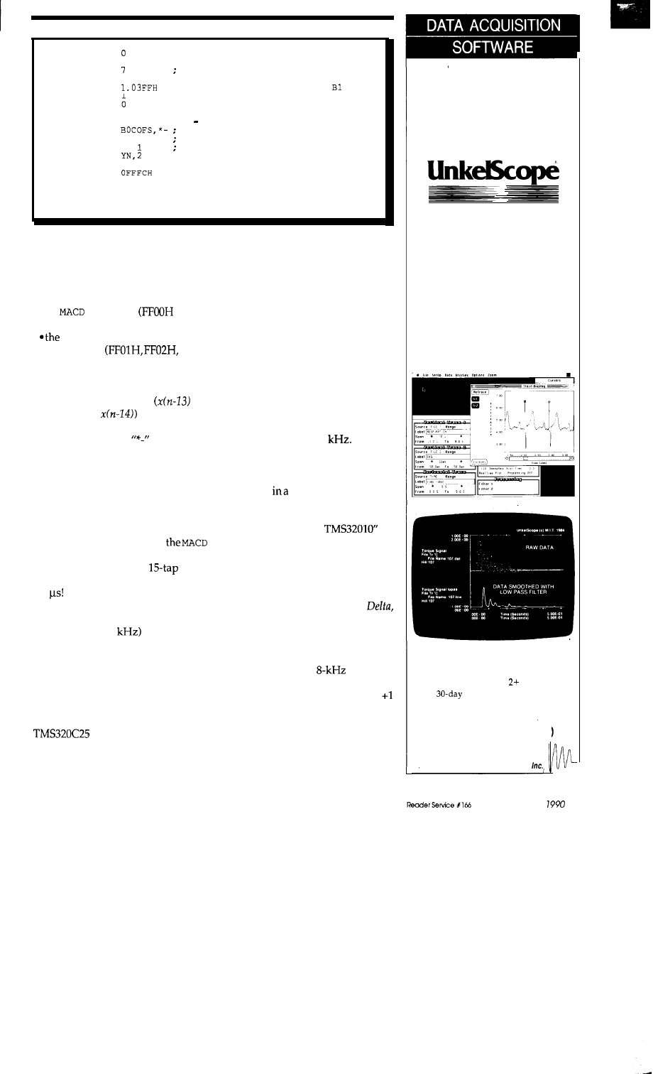
RINT:
LDPK
LAC
LDPK
SACL
LRLK
LARP
MPYK
ZAC
RPTK
MACD
APAC
SACH
LAC
LDPK
ANDK
SACL
EINT
RET
END
DRR
XN
LENGTH
YN,
0
DXR
; SELECT DATA PAGE 0
; READ INPUT SAMPLE FROM A/D
SELECT DATA PAGE 7
; STORE LATEST SAMPLE IN XN
; POINT AR1 TO BOTTOM OF BLOCK
; CLEAR P REG
; CLEAR ACCUMULATOR
; N 1 FILTER STAGES
MULTIPLY FILTER STAGES BY COEFFICIENTS
ACCUMULATE FINAL PRODUCT
STORE OUTPUT IN YN
; GET OUTPUT OF FILTER IN ACCUM
; SELECT DATA PAGE 0
; MASK OFF BITS
O-l FOR AIC
; OUTPUT TO D/A
Listing
1
-continued
. the data memory location pointed
to by the selected auxiliary regis-
ter is multiplied by the program
memory
location
specified within
the
instruction
start-
ing address)
program memory pointer is
incremented
etc.)
l
thedatamemorylocationpointed
to by the selected auxiliary regis-
ter is copied into the next higher
data memory location
is
copied into
*the selected auxiliary register is
decremented (the
within the
instruction
performs
this function)
When the MACD instruction is
placed after a
RPTK
N- 1 instruction,
the sequence shown above is repeated
N times.
As
discussed in the previous
article’s FIR filter example, this se-
quence is repeated 15 times. When
placed within the
RPTK
loop,
instruction requires a single cycle (100
ns at 40 MHz). So, for a
filter,
the sum-of-products loop takes only
1.5 To check out the operation of
the filter, you could sweep a function
generator signal (approximately 2 V
p-p from DC to 5
into the ADC
input while viewing the output (from
the D/A converter) on a dual-trace
oscilloscope.
SINE WAVE GENERATION
The high-speed nature of the
The program shown in Listing 2
makes it a natural for the
generates a standard telephone dial
generation of sinusoidal waveforms.
tone, which is the sum of 350-Hz and
Using a ROM look-up table which
440-Hz sinusoids.
ALP350 and
holds 128 entries of sine values from 0
DEL350 are variables used in the
to 360 degrees, we can generate a sine
wave of any frequency (within the
audio band) by stepping through the
table at a constant rate with a constant
step size. Of course, the accuracy of
the sine wave generated depends on
the number of points stored in the
table. But for our purposes, 128 table
entries will do.
The frequency of the sine wave
depends on the time interval between
output samples and the step size with
which we index into the sine table. To
simplify things, we will use a constant
output rate of, say, 10
The fre-
quency of the output waveform will
then depend only on the step size. The
step index must wrap around the end
of the table
“modulo 128” fashion.
See Listing 2,
DIAL
.
ASM
, an adapta-
tion of “Precision Digital Sine-Wave
Generation with the
by
Domingo Garcia, Texas Instruments
(found in “Digital Signal Processing
with the TMS320 Family, Volume I”).
Alpha
is
a variable which serves as a
modulo 128 counter/index which
cycles through the sine table.
the step size, is added to
Alpha each
time the routine is called.
In this
adaptation, the sine wave generation
subroutine will be called via a timer
interrupt set for an
rate. The
sine table entries are in two’s comple-
ment representation ranging from
to -1.
We’ll never
leave you
without
a trace
UnkelScope is an easy-to-use,
menu-driven software package
that will always leave you with
a clear, accurate trace. Whether
you’re in a laboratory or on
an oil rig in the North Atlantic,
UnkelScope will get the job done.
l
Full hardware speed
l
Real-time X-Y plots
l
Graphical Editing
l
Data Processing
l
Experiment Control
l
Plus much more
MAC Version
PC Version
UnkelScope JUNIOR
$125
UnkelScope for MAC
$149
UnkelScope Level
$549
money-back guarantee
(617) 861-0181
FAX (617) 861-1850
Unkel Software
62
Bridge Street, Lexington, MA 02173
A p r i l / M a y
5 3
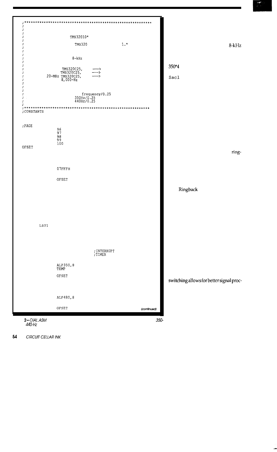
DIAL.ASM
This program generates a dial tone (350 Hz + 440 Hz).
It is an adaptation of:
"Precision Digital Sine-Wave
Generation with the
by Domingo Garcia, Texas
Instruments found in "Digital Signal Processing
Applications with the
Family, Volume
This program also demonstrates the use of the timer
interrupt.
We want a timer interrupt to occur every
125 microseconds (an
rate).
The PRD, period
register,
determines the number of clock cycles which
are counted down prior to a timer interrupt.
For a 40-MHz
PRD
1250,
For
a
36-MHz
PRD
1125,
For a
PRD
625,
to yield an
timeout rate.
The tone variables, Ton350 and Ton440, determine the
frequency of the resulting sine waves by the
formula:
tone = desired
For example:
Ton350 =
= 1400
and,
Ton440 =
= 1760
PRDVAL EQU
1125
TON350 EQU
1400
TON440 EQU
1760
0 VARIABLES
; value for 350 Hz
; value for 440 Hz
DEL350 EQU
ALP350 EQU
SIN350 EQU
TEMP
EQU
MASK
EQU
EQU
ALP480
EQU
DEL480 EQU
SIN480 EQU
TMPO
EQU
STRT:
LDPK
LALK
SACL
LALK
SACL
ZAC
SACL
SACL
LALK
SACL
LALK
SACL
LALK
SACL
LST
LALK
SACL
ZAC
SACL
LACK
SACL
LALK
SACL
LACK
SACL
EINT
LOOP: B
TMRINT: LAC
SACH
LAC
ADD
TBLR
LAC
ADD
AND
SACL
LAC
SACH
LAC
ADD
101
102
103
104
105
0
MASK
SINE
ALP350
ALP480
TON350
DEL350
TON440
DEL480
OEOOH
TMPO
TMPO
03FOH
TMPO
TMPO
TEMP
1
TMPO
PRDVAL
PRD
008H
IMR
LOOP
TEMP
SIN350
ALP350
DEL350
MASK
ALP350
TEMP
TEMP
;SET STATUS 0 REG
;SET STATUS 1 REG
;SET PRD REGISTER
;FOR A 8KHZ TIMEOUT
MASK FOR
INTR ONLY
RATE
generation of the 350-Hz sine wave
while
ALP
4 4 0
and
DEL4 4 0
are used
in the generation of the 440-Hz sine
wave.
TONE1
and
TONE2
are con-
stants to which the Delta variables are
initially set, respectively. At an
sampling rate, the constant equals the
desired frequency multiplied by four.
For example, the constant for 350Hzis
or 1400. Just prior to sending the
output to the D/A converter via the
DXR
instruction, the two sine
waves are scaled and added together.
Connecting the DAC output to an os-
cilloscope would show how the two
signals add together to form an envel-
oped waveform. Or, you could con-
nect theoutput to an audio amplifier/
speaker (such as the Radio Shack 277-
1008) to hear the dial tone.
GOING
FURTHER
We
could continue with the sine
wave table look-up theme to include
DTMF generation, busy tone,
back tone, error tone, and many oth-
ers. All it takes is a few calculations of
the Delta table index constants and
timing loops. For instance, a busy
tone is the
sum
of 480-and 620-Hz sine
waves pulsed on/off at a half-second
rate.
is the sum of 440 Hz
and 480 Hz waves turned on for one
second and turned off for three sec-
onds.
With constants having been cal-
culated for mark/space frequencies
along with the proper bit period tim-
ing, one could develop a simple FSK
modulator. At each bit boundary, a
mark or space frequency would be
selected depending on the next bit’s
value. Inherent in the look-up table
scheme, a transition from a mark to a
space (or vice versa) results in a change
of the table step size, providing a
phase-continuous waveform at bit
boundaries. Phase-continuous FSK
essing on the opposite end of the
modulation process (demodulation).
An analog FSK modulator which
switches between two free-running
oscillators (one for space, one for mark)
doesn’tprovidephasecontinuitysince
the two oscillators are asynchronous
with each other.
listing
generates a standard telephone dial
tone, which is the
sum of
Hz and
sinusoids.
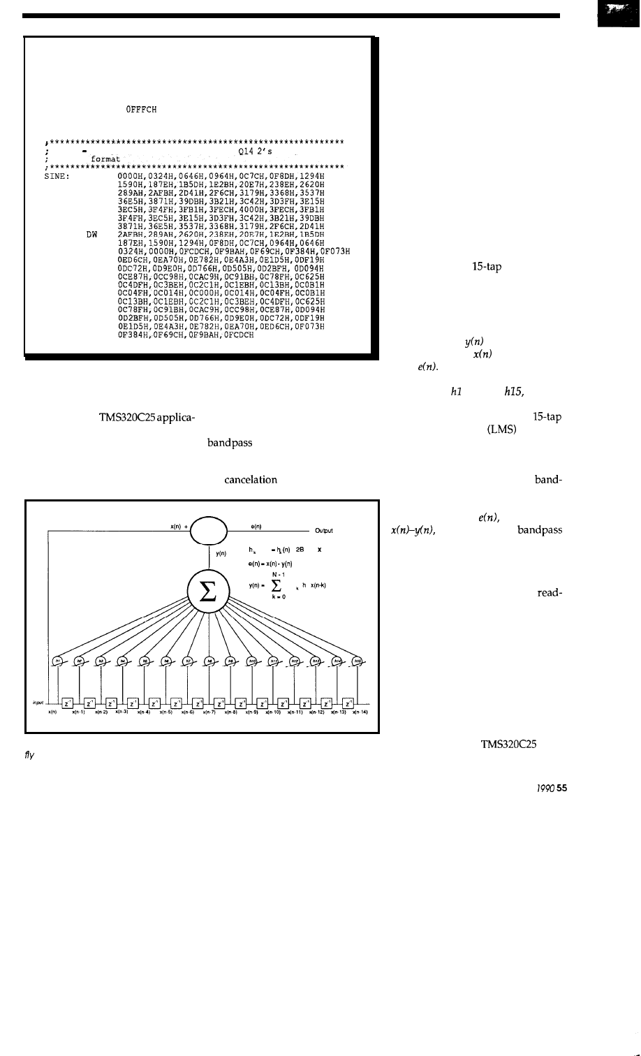
TBLR
SIN480
LAC
ALP480
ADD
DEL480
AND
MASK
SACL
ALP480
LAC
SIN350
ADD
SIN480
ANDK
SACL
DXR
EINT
RET
SINE 128
points of a sine wave in
complement
DW
DW
DW
DW
DW
DW
DW
DW
DW
DW
DW
DW
DW
DW
DW
DW
DW
DW
DW
END
Listing
2-continued
ADAPTIVE FILTERING
adapts or changes in real time to
minimize an error attribute. In the
In our last
case of the example that follows, the
tion, we will examine a fascinating
filter adapts its coefficients to form a
form of filters which actually adjust
filter which tracks periodic
themselves in real time. This form of
(sinusoidal) signals seen at its input.
filter is called an Adaptive Filter. It is
One use for an adaptive filter is
given the name “adaptive” because it
the
of unwanted periodic
(n-1)
+
e(n) (n-k)
Figure 5-A sump/e application is this adaptive filter which adjusts its coefficients on the
to cancel sinusoidal signals at its input.
signals (periodic noise). For instance,
an annoying 60-cycle hum corrupting
an audio signal, background motor
noise drowning out a speaker’s voice
over a telephone line, or an enemy
CW (continuous wave) jammer bury-
ing a weak friendly signal are all ex-
amples of
where adaptive
filters could
be applied.
You might ask why a notch filter
couldn’t be used? Well, notch filters
would be fine as
long
as
the frequency
of the interfering noise is known be-
forehand and doesn’t vary with time.
However, when the frequency is
unknown and/or varies with time,
the adaptive filter provides the best
solution.
In Figure 5, a
adaptive fil-
ter
is
shown.
Notice the arrow through
each of the fifteen coefficients indicat-
ing variable adjustment. Each time a
new input enters, the filter performs
its basic sum-of-products operation
yielding a new
output which is
subtracted from
to provide an
error,
With the error, adaptation
constant (Mu), and past x values, the
coefficients, through
are up-
dated.
An implementation of a
Least Mean Square
adaptive
filter,
ADAPT
.
ASM
,
can be found on
the Circuit Cellar BBS. Very quickly
after start of execution, this program
adjusts its coefficients to form a
pass filter matching periodic spectra
seen at its input. The output of the
adaptive filter,
is equal to
the output of the
subtracted from the input sequence.
To test the filter, one could feed a sine
wave into the ADC input and watch
the output of the DAC on an oscillo-
scope. Notice that after rapid
justmentsofthegenerator’sfrequency,
the DAC output diminishes to a low
level in a matter of milliseconds. The
adaptive filter automatically adjusts
itself to attenuate any sinusoid seen at
its input.
AND INTO THE FUTURE
In this article, we have provided
application examples featuring the
Texas Instruments
Digi-
tal Signal Processor. Other exciting
April/May
areas in the field of digital signal proc-
essing include speech voice coding
speech synthesis, speech
recognition, signal demodulation, and
spread spectrum communications, to
name a few. I believe that in the fu-
ture, digital signal processing will
replace many traditional analog cir-
cuit functions with software. DSP will
also make its way into “smart,”
effective sensors which will not only
detect the movement of a warm body
into or
out of a room, but will deter-
mine if the object is a dog, cat, child, or
adult. With this type of detailed sen-
sor information,
a master home com-
puter/controller could determine if
turning on or turning off room lights
is appropriate.
In the near term, general-purpose
DSP will likely
be applied to primarily
low-frequency audio band applica-
tions. As future generations of
and A/D converters increase in speed
and performance, digital signal proc-
essing will find widespread accep-
tance beyond the audio range and into
the VLF, LF, and HF RF
To facilitate experimentation in DSP applications, “DXP-25,” a PC-based
DSP development system is now being offered through:
571 Responsive Way
TX 75069
(214) 548-8503
Fax: (214) 548-1521
The $529 DXP-25 package includes a full-length PC/XT DSP card based on
a 36-MHz
DSP design, a resident monitor in EPROM (with associ-
ated PC host monitor control program), 8K words of l-wait-state user program
RAM,
words of l-wait-state data RAM, an
PC/DXP-25 communication
port, an
read/write I/O register block for PC/DXP-25 communication, a
TLC32044
ADC and DAC with programmable sampling rates up to 19.2
a
assembler, download utilities, and demonstration pro-
grams. Options include O-wait-state RAM, expansion RAM (up to 128K bytes
data RAM and 64K bytes program RAM), and a FIR filter design program.
Dean McConnell is a Senior Software
for
Rockwell International, Richardson,
Texas, where is
involved
with development
2 13
Very Useful
of
real-time computer-controlled
2 14 Moderately Useful
tion systems for the
215 Not Useful
Complete your
reference
library-
You
cannot
miss an issue of Circuit
INK
Issues through
(January/February 1988 -No-
vember/December
are available as a Bound
Offset Reprint of the First Year of Circuit Cellar INK.
Don’f miss ouf on the current
of this popular
technical resource! (Issues through are only
available in the reprint book, but issues
and
are
also available separately.) To order your copy of the
First Year of Circuit Cellar INK, send $20.00 ($24.00
foreign U.S. funds only) to:
Circuit Cellar INK First Year Reprint
4 Park Street
l
Vernon, CT 06066
or call
for immediate delivery!
For individual back issues
and
through
(January/February 1989 February/March
send $4.00 (check, VISA or
ac-
cepted) for each issue to:
Circuit Cellar INK Back Issues Sales
4 Park Street
l
Vernon, CT 06066
or call
875-2199
(NOTE: Issue
June/July 1989 is sold out.)
56
CELLAR INK
C
E
LL
AR
INK
C
ONTEST
is
4 , 1 9 9 0 .
entry by
5 : 0 0 EST
on
for consideration.
Mail all entries to:
C
E
LL
AR
INK
C
ONTEST
S
TREET
,
V
ERNON
, CT 06066
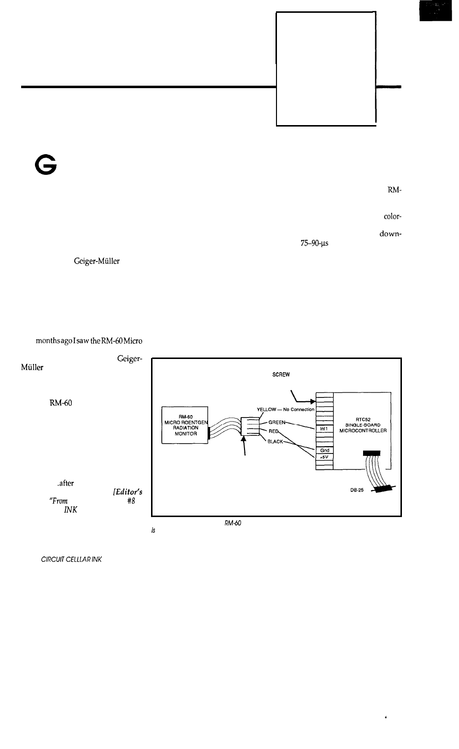
BASIC Radioactive
Randoms
FIRMWARE
FURNACE
Ed Nisley
enerating random num-
bers is a perennial-computer maga-
zine topic, but the articles always seem
to discuss the linear congruential or
software shift register implementa-
tions. While pseudo-random (pro-
nounced “fake random”) numbers
may be OK for computer science types,
Real Engineers get Real Random
Numbers by timing nuclear disinte-
grations with a
detec-
tor. When you want random num-
bers, why settle for less than the best?
The problem has always
been
that
you had to build a radiation detector
from scratch, adapt one from the sur-
plus market, or pay far too much for a
heavy-duty chunk of electronics with
far more features than you need. A
few
Roentgen Radiation Monitor from
Aware Electronics. It is a
tube that connects to a PC’s
parallel or serial port, with the cir-
cuitry drawing power from a single
interface pin.
The
costs under $100 in
onesies and comes with some reasona-
bly well-done software that turns your
PC into a Geiger counter, strip-chart
recorder, and data logger. All that is
well and good, but as soon as I saw the
gadget I realized that Real Random
Numbers were now within reach! All
I needed was an RTC52 and a little
firmware..
all, who wants to tie
up a PC to count fissions?
Note: See
the Bench” in issue of
C
IRCUIT
C
ELLAR
for
the design of the
RTC52 single-board controller.1
Although the RM-60 is interest-
ing, I thought this would provide a
good excuse to explore grafting as- make sure that the bits are actually
sembly language programs onto the arriving at the right ports. Figure 1
BASIC-52 interpreter. Measuring time shows the interface between the
intervals is a common industrial prob- 60 and an RTC52 board; while you can
lem and I have never met anyone who
certainly usedifferent computer hard-
wrote a BASIC program that ran fast ware, it’s hard to mess up three
enough.
coded wires.
I’ll start with a pure BASIC im-
plementation and wind up with a
BASIC language extensiondevoted to
returning random numbers. Along
the way you’ll learn more about the
innards of the BASIC interpreter than
ever showed up in the manuals.
The RM-60 produces a
going
pulse each time it de-
tects a radioactive decay particle. It is
sensitive to alpha, beta, and gamma
particles, but the output pulse is iden-
tical for all three because the detector
tube operates in Geiger mode. The
maximum count rate is thus over
10,000 counts per second...at which
point you have more than just a radon
problem in your basement.
BASICALLY RANDOM
Regardlessof how trivial the hard-
ware interface appears, you should
always write a simple test program to
The background radiation in my
office provides about 10-15 counts per
TERMINAL
CONNECTORS
MODULAR
PHONE
CONNECTOR
SERIAL
CONTROLLER
Figure
1
--Interfacing the
Micro Roentgen Radiation Monitor to a microcomputer
as easy as three wires.
58
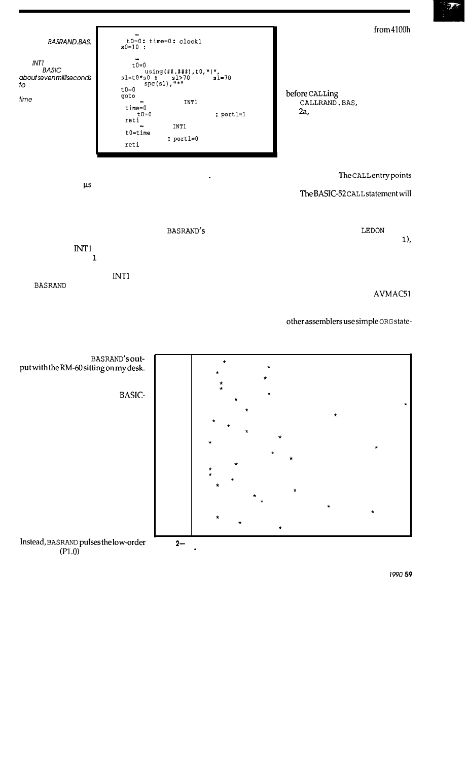
Listing
1 -This
BASIC-52
program,
measures the time inter-
val between pulses on
the
input pin. Be-
cause
requires
handle each interrupt,
it cannot resolve short
intervals.
100 rem set up things
110
120
rem scale factor
130 onexl 9010
200 rem reporting loop
210 if
got0 210
220 print
222
if
then
224 print
226
230
210
9000 rem beginning
pulse
9010
9012 if
then onexl 9110
9014
9100 rem ending
pulse
9110
9112 onexl 9010
9114
minute, with the time between counts
ranging from 100 to over 45 sec-
onds: after all, nuclear disintegrations
are random events. The firmware
should be able to cope with the short-
est possible interval, which, as we will
see, can be a problem with pure BA-
SIC code.
I chose the
input because
BASIC-52 has an
ONEX
statement that
branches to a specific line number
when a pulse occurs on the
pin.
The
program
shown
in List-
ing 1 uses a pair of interrupt routines
to measure the interval between two
successive pulses; the one at Line 9000
sets the
TIME
value to zero when the
first pulse occurs, while the one at
Line 9100 records the
T
IME
value at
the second pulse.
Figure 2 shows
Because the code requires two pulses
for each time interval, it can record at
most half the intervals. While
52 is a fast interpreter, it lacks the
speed for timing millisecond-length
events. The BASIC interrupt response
time is about 2 ms and the interrupt
handlers require about 5 ms each.
BASRAND cannot detect pulses oc-
curring during those times and will
return incorrect values.
The RTC52 board has an LED on
the 8052’s TO output (also known as
Port 3, Bit 4). While it would be com-
forting to blink the LED when the
program detects a pulse, the RTC52
was not designed to allow control of
that bit from a BASIC program.
bit of Port 1
which I watched on
an oscilloscope.. rest assured that the
remaining programs will blink the
LED!
CALLING THE COUNTER
peccadilloes may be
acceptable in some applications, but
there are others where returning the
wrong answer can be fatal. The solu-
tion is to capture the pulses using an
assembly language routine.
The CALL statement provides a
convenient way to invoke an assem-
bly language routine from BASIC.
CALL takes one argument, which may
be an integer from 0 through 127 or
any other unsigned 16-bit quantity.
The interpreter converts a value in the
first group into an address
through 41FEh and branches to that
location; values in the second group
are treated as exact branch addresses.
BASIC does not look before it leaps, so
it is your responsibility to have the
assembly language code in place
it.
shown in List-
ing uses the first method to
CALL
three routines.
CALL
0
and
C
ALL
1
turn that silly LED OFF and ON, re-
spectively, so the BASIC program can
indicate when it gets a pulse without
yourneedinganoscilloscope.
CALL
2
accesses the code that measures the
pulseintervals.
between 3 and 127 are not used.
not accept a variable as the parameter,
so you must code an integer. I favor
enumerated constants rather than
obscure digits (
CALL
would
be easier to decipher than CALL
but in this case it makes little differ-
ence.
The method you use to put your
assembly language code at the right
addresses dependson your assembler
and linker. The Avocet
macro assembler includes “segments”
thatcanbestartedatspecificaddresses;
ments to set the address. Despite the
bad reputation hardware segments
1.740
4.025
1.380
3.850
1.535
1.540
4.135
2.310
11.415
2.950
7.715
1.010
1.860
2.865
4.735
0.895
9.860
4.395
5.265
2.330
0.985
0.995
2.020
1.315
5.535
3.350
3.615
7.350
9.630
1.390
2.450
4.630
Figure
BASRAND displays the measured time interval and also converts the value info
a ‘bar chart. The intervals have a resolution of 5 milliseconds.
A p r i l / M a y
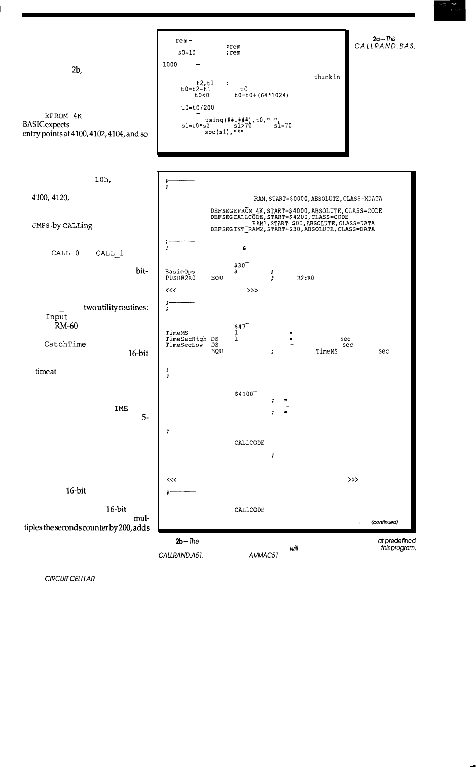
have gained from the IBM PC’s con-
voluted programming, software seg-
mentation is actually not a bad idea.
As you can see from CALLRAND.
A5 1 in Listing
much of the source
establishes the correct addresses for
code and variables in the BASIC inter-
preter. The critical addresses are the
three
AJMPS
starting at address 41OOh
in the
segment. Because
to find successive CALL
on, the two-byte
AJMP
instruction is
just what’s needed.
Of course, there is no reason why
the three routines couldn’t be accessed
using CALL 0, CALL
and CALL
2 0
h,
which would put the
entry points
at
and 4140, respectively
and eliminate the need for any
JMPS
at
all. You could also use three-byte
L
only even-num-
bered routines at the cost of one un-
used byte between successive
LJMPS
.
The
and
proce-
dures are only a few bytes long, as
they use the 8052’s S
ETB
and CLR
banging instructions to twiddle the
LED output. The listing omits the
latter routine to save space.
CALL 2 uses
Wait
stalls until the input bit
from the
matches the FO flag
and returns with interrupts disabled,
while
converts the (fro-
zen) BASIC
TIME
value into a
integer. The assembly code records
the
which two
successive
pulses
occur, leaving it to the BASIC pro-
gram to convert the values into a time
interval.
BASIC-52 provides a
T
func-
tion that returns the current time in
millisecond increments. The
CLOCK
1
and
CLOCK
0 statements start and
stop the clock, respectively, and the
current time is recorded in three bytes
in the 8052’s internal RAM. One byte
counts from 0 to 199, with one count
every 5 ms, while the remaining two
bytes are a
counter of whole
seconds.
To get
a consistent
value
from those three bytes, the code
the fractional seconds, and uses the
low-order 16 bits of the result.
The
result can time up to 327.68 seconds
60
INK
100
setup
110 call 0
turn
LED off
120
chart scale factor
130 clock 1
: rem start the clock
rem capture starting 6 ending times
1010 call 2
1020 call 1
: rem
turn
LED on while
1030 pop
rem t2 = stop, tl = start
1040
: rem
=
elapsed time
1050 if
then
:
1060
2000
2010
2020
2030
2100
2110
rem
fix 16 bit wrap
: rem
convert back to seconds
rem print a chart line
print
:
if
then
print
call 0
: rem turn
LED off again
got0 1000
listing
code,
CALL
S
three assem-
bly-language rou-
tines to time the
pulses and turn an
LED on and off. BA-
SIC is better at for-
matting the output,
while
assembler
handles the timings
and bit-banging with
aplomb.
Define segments
DEFSEGBAS
DEFSEGBAS-ROM,START=$OOOO,AESOLUTE,CLASS=CODE
DEFSEGINT
BASIC entry points constants
SEG
BAS
ROM
ORG
EQU
BASIC operations entry point
154
push
to arq stack
some code omitted
BASIC internal RAM variables
SEG
INT RAM2
ORG
DS
; 47 TIME value, 5 ms counter
; 48 TIME value,
(high byte)
1
; 49 TIME value,
(low byte)
MS-TICKS
200
number of
ticks per
.
-
-
I
BASIC CALL vectors
Must use 2-byte AJMP instructions to fit vector spacing!
SEG
EPROM 4K
ORG
AJMP
CALL 0
0 turn LED OFF
AJMP
CALL-
; 1 turn LED ON
AJMP CALL-2
2 return next random interva
.
-
,
Turn LED OFF
CALL-0
SEG
PROC
SETB
LED
LED OFF when output is high
RET
CALL-0
ENDPROC
CALL 1 is similar code that turns the LED ON
; Return next random interval
CALL-2
SEG
PROC
listing
BASIC CALL interface requires assembly code and variables
addresses. You can specify where your code wind up by using segments;
uses Avocet’s
macro assembler syntax.
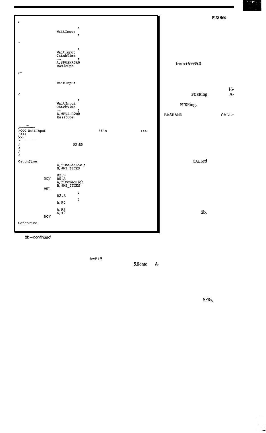
The assembly code
the
time at which the starting and ending
pulses occurred onto the A-stack, us-
ing a BASIC-52 routine that converts a
16-bit value into an equivalent float-
ing-point number. The times appear
to BASIC as values ranging from 0
through 65535.0, and the difference of
two such floating-point numbers can
range
through-65535.0
with no trouble: a timer wrap pro-
duces a negative value, which the code
corrects by adding 64K.
The whole process of capturing
the current time, converting it to a
bit value, and
it onto the
stack takes about 1 ms, most of which
is spent
While this is much
better than 7 milliseconds for the
interrupt handler,
RAND can still miss a pulse while it’s
busy and report the wrong time inter-
val.
Before going into the third pro-
gram, a digression is in order: how do
you get assembly language routines
working in the first place? After all,
BASIC’s built-in debugging facilities
are useless for
routines. The
answer involves some software, some
hardware, and some firmware.
ADDRESSEE UNKNOWN?
The first step, of course, is to co-
erce your assembler into producing a
hex file with instructions at the right
addresses. Whetheryouusesegments,
as shown in Listing or
ORGS
, as you
might withanotherassembler,theend
product is a hex file you burn into an
EPROM and stick into a socket on
your 8052 board.
But, more likely than not, when
you turn the power on and run that
first version, the CPU will lock up and
die. How do you find out what’s
wrong?
The first, and cheapest, line of de-
fense is a software simulator that runs
on your PC, reads the hex file (and
perhaps the linker’s MAP file), and
simulates the action of the 8052 CPU
while running your code. Because the
simulator displays all of the internal
registers, RAM, and
you can be
very confident that your program will
actually do what you intend. And,
-- ensure no
input pulse right now...
SETB FO
ON = inactive
CALL
SETB EA
turn interrupts back on again
-- wait for starting pulse and capture current time
CLR FO
OFF = active
CALL
CALL
SETB EA
allow interrupts now
MOV
LCALL
make sure pulse has gone away
SETB FO
; ON = inactive
CALL
SETB EA
-- wait for ending pulse and capture time again
CLR FO
ON = inactive
CALL
CALL
SETB EA
allow interrupts now
MOV
LCALL
RET
CALL 2
ENDPROC
routine omitted because
pretty obvious
it returns with interrupts disabled to allow time capture
,
Capture current time in
Convert time to linear count as
(seconds * counts/second) + counts
Interrupts must be OFF to ensure that time doesn't change!
PROC
MOV
form
low partial product
MOV
MUL AB
MOV
; save it
MOV
;
form high partial product
MOV
AB
ADD
A, R2
combine high part of low partial
MOV
MOV
A,TimeMS
combine with ms counter
ADD
MOV
RO,A
MOV
ADDC
R2.A
RET
ENDPROC
END
Listing
before wrapping, and the wraps are
easy to detect in BASIC.
Although some assembly routines
(such as the LED control procedures)
don’t return any data, ones like
C
ALL
2
pose
a
problem. BASIC stores
variables as 6-byte packed BCD float-
ing-point numbers, quite different
from the one- or two-byte integers
with which you are familiar. How do
you convert between formats?
The solution is the BASIC-52
Argument Stack, which BASIC uses
during expression evaluation. The
interpreter parses a statement such as
by pushing the values of
variable B and constant
the
stack, calling a routine that adds the
top two elements, then popping the
result into the location of variable A.
The PUSH and
POP
statements give
you direct control over the contents of
the A-stack,
and utility routines acces-
sible from assembly language allow
you to POP and PUSH floating-point
numbers, integers, and suchlike.
62
CIRCUIT CEL LLAR INK
because the simulator doesn’t depend
on the actual 8052 hardware, your
program can’t crash the system by
doing something really stupid.
Simulatingyourcodeisone thing,
but how can
sure that you have
all the interfaces between it and the
BASIC interpreter correct? The an-
swer is easy, but not obvious: simu-
late the whole BASIC interpreter along
with your (teeny) program!
The key is to get the interpreter
code as a hex file that you can feed
into the simulator. To do so, you can
actually extract the code directly from
whatever processor chip you’ve got.
Without going into the grim details,
this program fragment will dump the
entire contents of the internal ROM
on the console:
FOR i=O to lfffh
: NEXT i
Of course, you must wrap a bit of
code around that core to output the
data in
standard Intel hex format, then
capture the console output to a PC
disk file, but the process is not particu-
larly difficult and serves as a good
learning experience. Hint: you need
to write a routine that converts a vari-
able into two or four hex digits and
displays the results on the console. As
you’ll find out, the
PH
0 statement
pends a blank and appends an “H”
character, making it useless for pre-
cisely formatted output.
And a caveat: the interpreter is
both copyrighted and
mask
registered,
so you need to be careful about mak-
ing duplicates.
Anyhow, once you have loaded
both BASIC-52 and your code into the
simulator and fired it up, you can, no
kidding, type BASIC code directly into
the (simulated) serial port! It runs
rather slower than real time, but works
precisely like the real system. You can
set code breakpoints and single-step
right through the interface. After you
have done this a few times, you can be
quite sure that your code will work
the first time in real hardware.
Al though you can bum your hex
file into an EPROM, you may want to
use an EPROM emulator instead. I’ve
been using the Parallax 2764 EPROM
emulator for a few months and find it
to be an invaluable tool. You’ve seen
the picture in ads, but the real charm
of the device is that it uses
mount components on a circuit board
that is only slightly larger than the
2764 EPROM it replaces.
The board connects to the parallel
port on your PC through a modular
phone cable. The
program trans-
fers a hex file through the cable to the
emulator hardwareand-poof!-your
program is available to the 8052 as if
you had burned an EPROM. EM64
has several other useful tricks up its
sleeve, but the hex file loader gets the
most use. The gadget is an example of
clean, simple, dedicated design that
does one job and does it well.
It would nice to have a full
circuit emulator to provide hardware
breakpoints, true single-stepping,and
suchlike when the program is
Featuring
l
Standard RS-232
Serial Asynchronous ASCII Communications
l
48 Character LCD Display (2 Lines of 24 each)
l
24 Key Membrane Keyboard with embossed graphics.
l
Ten key numeric array plus programmable function keys.
l
Four-wire multidrop protocol mode.
l
Keyboard selectable SET-UP features-baud rates, parity, etc.
Size (5.625” W x 6.9” D 1.75” H). Weight 1.25
l
5 7 Dot Matrix font with underline cursor
l
Displays 96 Character ASCII Set (upper and lower case)
Options-backlighting for
RS-422 20 Ma current loop
302 N. Winchester
l
Dlathe, KS 66062
l
800-255-3739
A rugged
CASE? lined
with
plenty of foam for
your equipment can
TAKE A LOAD OFF YOUR MIND
when you’ve got to travel.
TAKE A LOAD OFF YOUR BACK
with our exclusive tilt-wheels
and extension handle option.
UNLOAD ON US!
Call or write to tell us about your
shipping or carrying problems
WE HAVE SOLUTIONS!
CABBAGE CASES, INC.
1166-C STEE
ROAD
OHIO
(614) 486-2495
FAX (614) 486-2788
(800) 888-2495
A p r i l / M a y
63
Xl 14
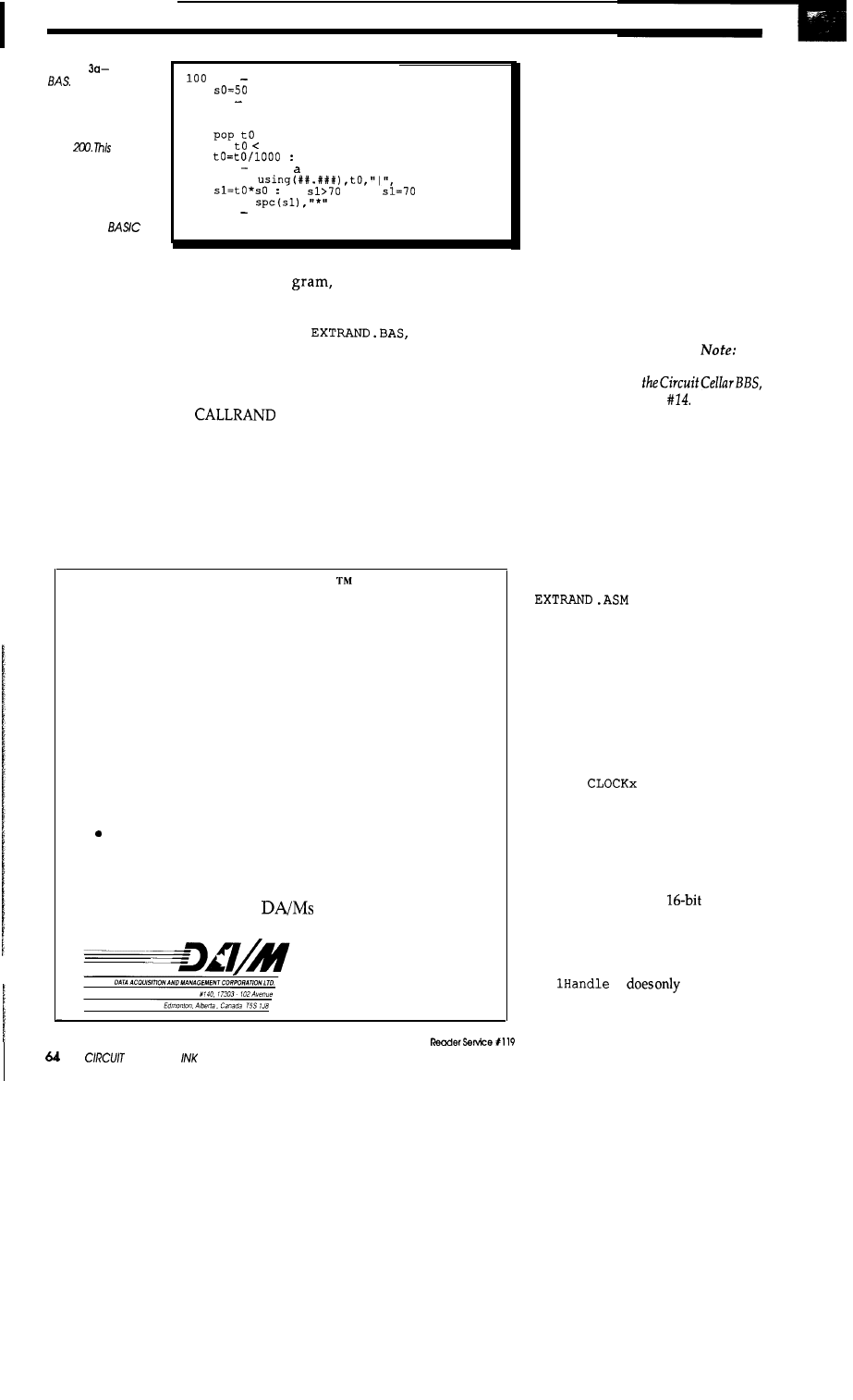
Listing
EXTRAND.
A cleaner way
to add functions to
BASIC-52 uses the
built-in language ex-
tension feature, as in
Line
example
adds a single
key-
word, but more com-
plex code can have
additionaiarguments
that may include
complete
ex-
pressions.
110
200
210
220
230
240
300
310
320
330
400
410
rem setup
rem
get the next interval, spin if not
available
random
if
0 got0 210
rem convert to milliseconds
rem print chart line
print
if
then
print
rem back to the top
got0 200
ning on the real hardware, but I find
that the combination of a software
simulator, an EPROM emulator, and
some careful coding work nearly as
well for the problems I need to solve.
KEY WORDS
But, for all of that,
can still miss an occasional pulse while
it’s pushing values on the A-stack
because two pulses may occur faster
than the code can absorb them. The
solution is to put all of the pulse tim-
ing into an assembly routine and leave
the console output to the BASIC pro-
which
is just what
EXTRAND
.
BAS
in Listing 3a does.
If you take a close look at Line 210
in
you’ll see the
keyword
RAN
DOM
,
which you won’t
find in your BASIC-52 manual.
RAN
-
DOM
,
as you might guess, puts the next
random time interval from the assem-
bly language routine on the A-stack,
ready for the
POP
in Line 220.
Admittedly, the
CALL
interface
from
CALLRAND
.
BAS
would work as
well for this code, but I find that the
slight extra effort required to integrate
new functions right into the language
pays off handsomely.
RAN
DOM
makes
The DA/M
The Lowest Cost Data Acquisition System
Our DA/M can solve more of your data acquisition
problems at a lower price than any other product on the
market. DA/M’s are used for:
l
Military meteorological stations.
. Building management.
l
Automated hydroponic farming.
l
Industrial process control.
Your application
In fact, DA/M’s can be used whenever you can’t afford
to use any one else’s product.
Made in North America,
are available NOW!
Phone
l-403-486-3534
Fax
l-403-486-3535
much more sense thananopaque
C
ALL
2, particularly after a few months on a
different project.
Although the BASIC keyword
interface is somewhat more complex,
the bulk of the code in
EXTRAND
.
ASM
is due to its improved capabilities.
EXTRAND
records times to the nearest
millisecond, can’t missaninput pulse,
and blinks the LED automatically...
what more can you ask?
TIME FOR A BUFFER
Unfortunately, the full listing for
EXTRAND
.
ASM
won’t fit in the pages
Curt gives me, but you can download
it from the BBS.
[Editor’s
The
software for this article is available for
downloadingfrom
or on Software on Disk
See page 84
for information on downloading and or-
dering all the software from this issue.]
For our purposes here, there are two
sections of interest: the interrupt rou-
tine that captures the pulse timing
and the BASIC keyword interface.
Before that code can do anything
useful, though, the code must repro-
gram some of the 8052’s hardware.
BASIC-52 passes control to a “user
reset” after a power-on reset, so
can set the serial bit
rate, set Timer 0 to count l-millisec-
ond ticks, define a handler for Exter-
nal Interrupt 1 that gets control on
down-going edges, and performother
housekeeping functions with no
trouble at all.
Because Timer 0 runs at five times
the normal rate,
EXTRAND
.
ASM
also
includes an interrupt handler to incre-
ment the variables BASIC uses for the
TIME
and
functions, but only
every five ticks. In effect, the BASIC
program behaves as though
CLOCK1
were always in effect, so you can’t
turn off the clock without disturbing
the
EXTRAND
interrupt handler. In
addition,
EXTRAND
increments
Elapsed, a separate
counter,
every millisecond.
The code shown in Listing 3b gets
control whenever the RM-60 detector
produces an
output pulse.
Ext
r
three things:
copy thecurrent contentsof Elapsed
into a ring buffer, clear Elapsed to
CEL LLA R
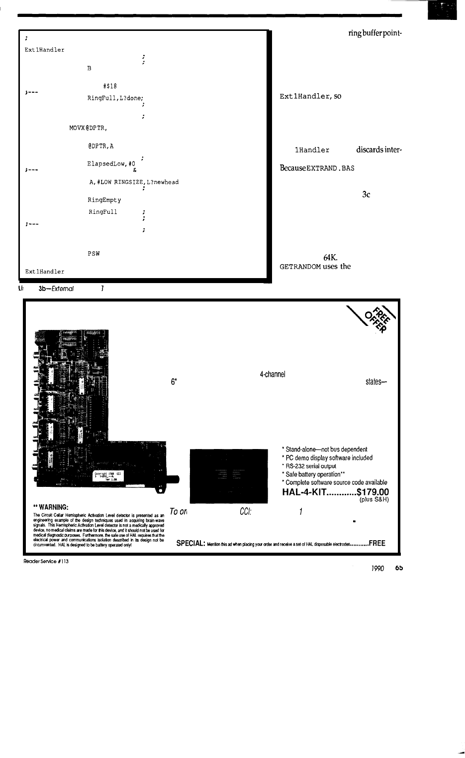
PSW is pushed by BASIC interrupt handler code
SEG EXTCODE
PROC
CLR LED
mark an incoming pulse
PUSH ACC
save bystanders
PUSH
PUSH DPH
PUSH DPL
ORL PSW,
; select bank 3
capture current time in ring buffer
JB
skip if full
MOV DPH,RingPaqe
get ring head pointer
MOV DPL,RinqHead
CLR EA
ensure time stands still
MOV A,ElapsedHigh ; transfer to ring
A
INC DPTR
MOV A,ElapsedLow
MOVX
INC DPTR
MOV ElapsedHiqh,#O reset counters
MOV
update ring head pointer check for full
MOV A,DPL
CJNE
CLR A
reset to start of buffer
L?newhead
MOV RingHead,A
CLR
;
have at least one entry!
CJNE A,RingTail,L?nohit ; head = tail means ring full
SETB
so mark it
L?nohit
SETB EA
timer ticks OK now
return to interrupted code
L?done
POP DPL
restore bystanders
POP DPH
POP B
POP ACC
POP
; restore this one
SETB LED
; turn off marker
RET1
ENDPROC
sting
interrupt handler routine.
zero,andupdate the
ers. As I’ve discussed ring buffers in
previous columns, there isn’t much to
say about this function. One “gotcha”
is that BASIC catches External Inter-
rupt 1 first and pushes the 8052 PSW
register onto the stack before calling
whatmayappear
as an unbalanced
POP
just before the
RET
is actually a required statement.
The ring buffer is 256 bytes long,
so it can hold up to 128 two-byte time
interval entries before overflowing.
Ext
simply
rupts that occur when the ring is full.
hasnotrouble
keeping up with the average pulse
rate the buffer never fills up.
The code in Listing removes
entries from the ring buffer and re-
turns them on the BASIC argument
stack. It uses the BASIC routine that
converts a 16-bit integer into a float-
ing-point number and pushes the
result, which can return values from
zero through
If the ring is empty,
PUSHFPC
r o u -
tine to push the floating-point value
-1 .O directly onto the stack.
Build Steve Ciarcia’s
HAL-4
EEG Biofeedback Brainwave Analyzer
\
Ever wanted to build a brainwave analyzer; one that wasn’t a toy; one with graphic display
capability? Circuit Cellar is proud to introduce Steve Ciarcia’s new Hemispheric Activation Level
detector (HAL, for short).
The HAL-4 kit is a complete battery-operated
electroencephalograph (EEG) which
measures a mere x 7”. HAL is sensitive enough to even distinguish different conscious
between concentrated mental activity and pleasant daydreaming. HAL gathers all relevent alpha,
beta, and theta brainwave signals within the range of 4-20 Hz and presents it in a serial digitized format
that can be easily recorded or analyzed.
HAL’s operation is straightforward. HAL samples four channels of analog brainwave data
64
times per second and transmits this digitized data serially to a PC at 4800 bps. There, using a Fast
Fourier Transform to determine frequency, amplitude, and phase components, the results are
graphically displayed in real time for each side of the brain.
der please call (203) 875-275
Circuit Cellar Inc.
TELEX: 643331
4
Park St. Suite 12
FAX: (203) 872-2204
Vernon, CT 06066
April/May
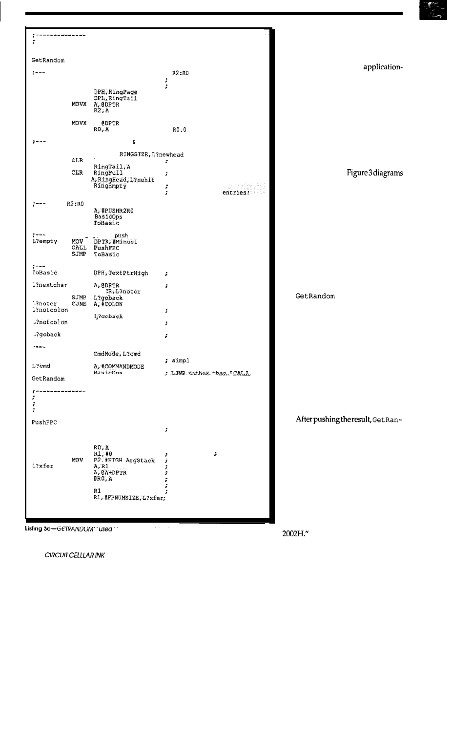
Return next random number from ring
SEG
EXTCODE
PROC
extract the current ring entry to
JB
RingEmpty,L?empty
CLR EA
ring empty?
MOV
can't change ring now
MOV
MOV
; R0.2
INC
DPTR
A,
MOV
;
INC
DPTR
tick ring tail pointer check for empty
MOV
A,DPL
CJNE A,#LOW
A
reset to start of buffer
L?newhead MOV
at least one empty slot
CJNE
; head = tail: ring empty
SETB
so mark it
L?nohit
SETB EA
OK to add new
push
on BASIC's Argument stack
MOV
LCALL
SJMP
ring is empty,
so
return value = -1
step BASIC's text pointer to the end of the line
MOV
MOV
DPL,TextPtrLow
set up BASIC text pointer
MOVX
at CR?
CJNE A,#<
at colon?
SJMP
INC
DPTR
nope,
continue
SJMP
L?nextchar
MOV
TextPtrHigh,DPH
MOV
restore BASIC text ptr
TextPtrLow,DPL
if in command mo de, restart the interpreter's READY mode
JB
RET
e RET in RUN mode
MOV
LJMP
ENDPROC
Push floating-point number at DPTR in code space to Argument
stack.
Number is stored with exponent at first byte to
simplify addressing.
PROC
MOV
ADD
MOV
MOV
MOV
MOV
A,ArgSP
make room on arg stack
A,#-FPNUMSIZE
ArqSP,A
; ptr to strt of stack slot
byte offset counter
page in Extexnal RAM
byte offset
MOVC
MOVX
DEC
INC
CJNE
RET
get byte from code space
drop onto stack
RO
tick target addr downward
tick offset
do for all bytes
?ushFPC
ENDPROC
IS
To remove entries from
BASIC.
the ring buffer andreturn them to
66
NEW WORDS
Unlike most computer languages,
BASIC-52 allows you to add new
keywords to perform
specific tasks. The interface between
the BASIC interpreter and your code
is quite clean, but you have to get all
the steps correct or it just won’t work
right.
You can think of the process as an
intelligence test for your code: during
the power-on reset, the BASIC inter-
preter makes sure that your code ex-
ists and can respond to requests. After
it’s qualified, BASIC skips the tests
and callsitdirectly.
everything you need to know to set
this up; the source code is available on
the BBS.
BASIC needs to know two things
about each new keyword: the ASCII
text of the keyword and the addressof
the code that carries out the function.
Both of these are stored in tables, so,
once you get a single keyword func-
tioning, it’s easy to add more. There is
an upper limit of 16 new keywords,
but each of those can provide
multiple
functions.
doesn’t require any
parameters, but your routines can
examine the rest of the BASIC line and
extract other information. BASIC
includes functions
to interpret expres-
sions and return a value, so the BASIC
source can include any valid BASIC
variables, constants, or expressions.
If your new keyword needs to
return a value, you can push it on the
stack or store it in a known address
above
MTOP.
Of course, if your rou-
tine has only “side effects” it doesn’t
have to return anything at all.
dom must adjust BASIC’s text pointer
variables to the end of the source code
line and return control to the inter-
preter. These functions are required
at the end of the routines that add new
keywords to the BASIC-52 language,
so you’ll have to include them in your
code regardless of what else it does.
Now, here’s another gotcha. Ac-
cording to the manual, “when MCS
BASIC-52 enters the command mode
it will examine code memory location
Guess what happens if the
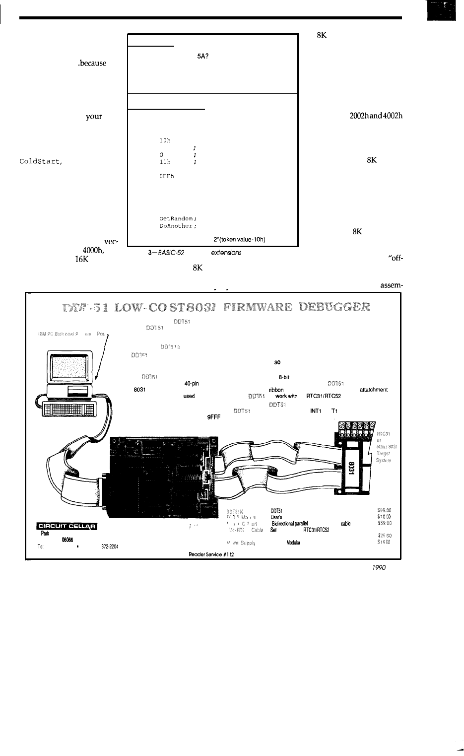
initialization code detects a
valid BASIC program in
EPROM?
During startup
an
EPROM emulator, as I
do.
Exactly right..
the
interpreter doesn’t enter com-
mand mode, it never calls your
routines that enable the new
keywords, so the keywordsare
not valid, so BASIC-52 reports
a
SYNTAX ERROR at
first
new keyword!
Fortunately, the solution
is trivial: if you set that bit
during your reset code (in
forexample), the
extensions will be enabled.
Your reset code must check for
the program in EPROM and
set the BASIC program point-
ers appropriately.
Code address 2002 =
No-extensions are not in effect
CALL routine at 2048
If it sets bit 25.5 hex, extensions are in effect
During
BASIC execution
CALL routine at 2078
Sets DPTR to address of token/keyword table:
DB
; first token value
DB
"RANDOM"
first new keyword
DB
separator
DB
second token value
DB
"ANOTHER";
second new keyword
DB
; table terminator
On the RTC52 boards,
you need to install the jump-
ers that specify a 2764
EPROM, then two jumpers
that select address ranges
2000h and 4000h. The EPROM
is selected for both ranges, so
references to
refer to the same address and
return the same value. As the
EPROM must be in code
space, only socket U8 fills the
bill; U9 holds an or 32K
RAM in data space.
The Parallax ROM Emu-
OVERLAID CODE
If keyword is found in table,
lator software includes an
CALL routine at 2070
“offset” value that specifies
Sets DPTR to address of routine vector table:
the EPROM’s starting address
DB
address of RANDOM routine
in the target system. The pro-
DB
address of ANOTHER routine
gram transfers only the hex
values within bytes of that
CALL address at table entry
starting address, so you must
Figure
keyword
make two passes through the
file with two different
code space. However, because it uses
into a single EPROM as long as it
set” values. If you needed to do this
only a few hundred bytes, all of the
responds to both address ranges. This
on a regular basis, it would make sense
BASIC-52 vectors and code will fit
trick comes in handy if you have only
to tinker up some conditional
EXTRAND .A51 uses
torsnear 2000h and
so it
should require
bytes in
The Circuit Cellar
takes 3031 firmware development out of the stratosphere and down to reality! Simply
connect the
between your IBM PC and a target 8031 board and you can: download firmware into RAM on your
8031 board, single-step or breakpoint your code, examine and change the ALU registers, and directly troubleshoot
application firmware on your 13031 board without leaving your PC. Once you have fully debugged code, simply save it
to EPROM on the
built-in EPROM programmer.
is a complete kit that provides the essential functions you need to get your code working! We provide the
source code for both the PC debugger and the 8031 firmware kernel,
you
can tailor the system to match your unique
requirements. We even include
a
shareware 3051 cross-assembler so you can get started immediately.
The
connects to any IBM PC parallel printer port which is
bidirectional (we have them if yours is just
printer output compatible). A
ribbon cable “DIP-Clip” adapter (user supplied) from the
simply clips on top
of the
chip in the target system. Alternatively. a straight
cable connector-to-connector
(optionally available) can be
to directly interface the
and
the
as a target system.
Ofcourse. infiniteflexibilty is the realm of high-priced brands.
may not be compatible with all possible 3031
boards, but new designs can easily accommodate
if you give it access to the
and
pins, and allow it use
of RAM addresses between 8000 and
hex. It’s straightforward as well as cost-effective.
4
Street
Vernon, CT
(203) 8752751 Fax: (203)
full kit w/manual. programs, and source code
manual only
port board and
of DDT51 to
ribbon cable
connectors and jumper header
DDT51
Power Supply
April/May
67
Col Program
1
BASRAND 0.005
2
0.005
3 EXTRAND 0.001
4 EXTRAND 0.001
1 2
-
-
0.765 0.020
0.165 0.500
0 . 8 7 0 0 . 1 3 0
0.625 0.495
2.310 0.780
1.060 0.540
0.295 0.530
0.735 0.170
0.535 0.315
0.255 0.030
1.505 0.830
1.140 0.945
1.015 0.890
0.755 0.100
0.905 0.320
0.525 0.365
Comments
Radium watch on top of
RM-60 detector tube
Radium watch on top of
RM-60 detector tube
Radium watch in front of
RM-60 detector window
Background radiation
3
4
-
-
0.037
9.213
0.020
4.947
0.017
3.226
0.057
0.397
0.259
6.255
0.016
6.921
0.142
4.721
0.051
1.187
0.024
1.362
0.011
17.738
0.033
3.768
0.207
1.092
0.042
1.229
0.031
2.535
0.005
3.114
0.011
10.772
in the text.
time intervals are in sec-
onds. The downloadable file includes
numbers in each set.
statements
to shuffle the segments
around and get a single 8K hex file
with all the code in the “wrapped” ad-
dresses.
IS IT RANDOM OR IS IT HOOEY?
Volume 2 of Knuth’s
The Art of
Computer Programming
contains an
extensive summary of tests to sepa-
rate random number generators into
the good, the bad, and the awful. As
he points out, the tests are mostly of
use to people who are determined to
put someone else’s generator in the
latter category..
I collected four sets of 1000 con-
secutive random numbers using the
three programs under various condi-
tions and ran a few simple tests using
the Excel spreadsheet (see Figure
The raw data are recorded in a file
available for downloading from the
Circuit Cellar BBS; you can run more
extensive tests if you feel the need to
discredit my technique!
A histogram shows that the ran-
dom intervals are not uniformly dis-
tributed; there is a definite peak
around an “average” value,but you’ll
find all values betweenzero and huge.
The “average” value depends on the
radiation level, so dropping a radium
watch on the detector will certainly
change the characteristics of the ran-
dom numbers.
From what little I remember from
my courses in probability theory, the
curve resembles a Poisson distribu-
tion. A quick thumb check of the text
confirmed a suspicion I’ve had for
awhile: I was considerably smarter in
my younger days. If any of you have
current experience with this stuff, do,
please, take a look at the data and see
if it makes any sense!
However, one thing is clear from
my observations: unlike the fake ran-
dom number generators you find in
the other articles, Real Radioactive
Randoms won’t repeat no matter how
long you wait... and that counts for
something!
Ed
is a member of the Circuit Cellar
INK engineering staff and enjoys making
gizmos do strange and wondrous things. He
is, by turns, a beekeeper, bicyclist, Registered
Professional Engineer, and amateur racon-
teur.
IRS
2 16
Very Useful
217 Moderately Useful
2 18 Not Useful
tive,
projects
a touch-tone interactive
message system...the world’s
smallest
modem...a
turnkey bulletin board
audio and video multiplexer...an ana-
log to digital converter...a serial Eprom
programmer.
much more.
256 pages, 100 illustrations.
CIARCIA’S
CIRCUIT CELLAR
Volumes
I-VII $21.95 each
GLS Generic Logic Simulator
brings powerful logic simulation techniques and unique capabilities a
Very low cost. With internally supported bus architectures,
takes
simple gate-level designs to programmable arrays,
o memory-based systems
to
control and computer ALU implementations, to serial
data processing... and beyond, in the fast lane. Now you can pu
ogether, not just simple logic circuits, but complex digital
just a few minutes. That’s SIMULATION POWER at your
GATES
ADDERS
FLIP-FLOPS
431 Hidden Meadow Dr
COUNTERS
7
VA 22033
DECODERS
68
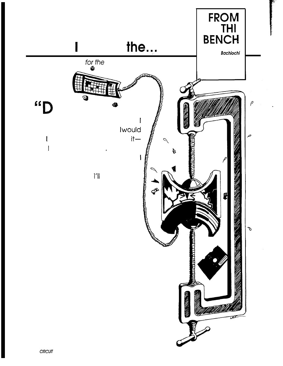
Honey, Shrunk
New Uses Abound
Smallest AT-Clone Yet
on’t you dare bring another
piece of equipment into this house!”
knew those were the words
hear. wouldn’t even chance
Unless, could somehow.. ‘Naw, that
couldn’t possibly work, or could it?”
mumbled to myself. It certainly was
worth a try. Let’s see, start with this
old Model I, The covering of dust
which had settled like a blanket on my
old friend was an indication of the last
time I’d seen the TRSDOS sign-on mes-
sage. “Look at all these single-sided
diskettes,” I thought. “I could put ten
of these on one high-density floppy
now.”
I called to one of my sons for help,
“Dan, help me carry this stuff out of
here, OK?” I instructed him to use the
front door and load the car. After
complaining that the car was much
closer to the back door, I explained
there was a method to my madness.
‘If you use the front door Mom will see
you.” ‘So what?” Dan argued. “She’s
Jeff
70
CELLAR INK
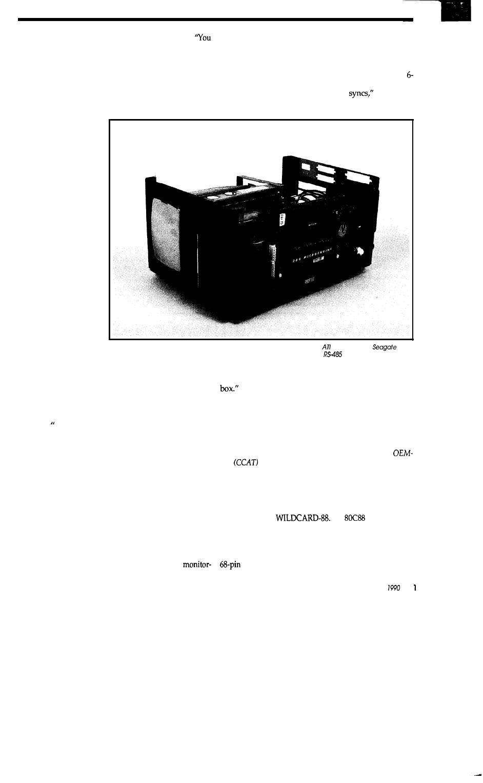
sure to wonder what we’re doing,” I answered back.
see,” I continued, “I don’t think she’s ever seen any equip-
ment going out! It’s sure to spark her curiosity.”
I returned to the scene of the yet-to-be-committed
crime and viewed the now-empty void, nestled right
between the XT and the oscilloscope. This was practically
the only free space left in the house. You see, we are about
to add on to this crackerbox, since space is at such a pre-
mium.
ing system which is compact yet powerful enough to allow
software development and program maintenance. Rum-
maging through my flea market leftovers was easy; not
much was left. It seems it’s getting tougher and tougher to
find good junk, er, equipment nowadays. I did find a
inch monitor in the heap, but it’s not even composite video.
“It’ll need horizontal and vertical
I thought.
“Humph, no enclosures. Wait, the TRS-80 I just removed
“This old vacuum
should do the trick,” I
thought to myself. As I
switched it on, a puff of
something blew out the
back, like starting a car
that was badly in need of
a ring job. The roar was
deafening. I went right
to work cleaning up what
was left behind. You
know the kind of stuff
I’m talking about: bits ‘n
pieces of the cosmos.
Even God couldn’t ex-
plain how it got there.
It didn’t take long for
the curiosity to build to a
level of investigation.
“Wh...on... hmmf,” I
heard as my wife poked
her head around the cor-
ner. I powered down the
01’ sucker and asked
“What?” as a final puff
blew out of the vacuum,
like a dying gasp. ‘You
killed it,” she gleamed,
The Home Monitoring System is made up of a Mitsumi 286 Microengine, EGA Wonder,
ST-02
floppy/hard disk controller, 3.5’ floppy drive, 3.5’ hard drive, Metrabyfe
serial interface. and an
Audiotronics 5-inch monitor. all in an lntegrand enclosure.
certifying the need for a new one.
I knew this was it, time for that costly phrase. “Yeah,
I guess you can start shopping around for a new one.” Her
face paled, as if hypnotized. “By the way,” I added, “This
is where I’m going to install our new Home Monitoring
System.” That’s nice,” I heard her say, but I knew she
meant, “Where’s the checkbook?” We were both happy
now.
ONE FOR ALL AND ALL IN ONE
The Home Monitoring System will take years to
complete. In fact, it is one of those projects that just keeps
on growing. Adding the extra wiring necessary for home
monitoring is much easier to accomplish during the fram-
ing stage of building. Now is the time to prepare, before
construction of the addition actually begins. Did I say
addition? This is more like adding a house to an already
existing garage.
Cramming things into small spaces has become the
norm at our house. So naturally I’d like a home
had two full-sized floppy drives mounted in an external
I carefully smuggled the appropriate equipment back
into the house. Upon ripping out the old drives, I smiled
as I noticed its built-in power supply. “Look at that, the
monitor even fits.” Now with a four-slot PC-style passive
backplane, yeah, and 3.5-inch drives, that’s it.
That’s not it. There is no room for any full-length PC
boards
like
the OEM-286. Rats! [Editor’s Note:The
286
was presented in ‘Garcia’s Circuit Cellar” in the
September/October 1987 issues of BYTE.1
THE BIG SQUEEZE
Intel entered the miniaturized computer market in
1988 with their
An
PC/XT-com-
patible motherboard on a small 2x4-inch form factor. Un-
fortunately, DRAM and DRAM drivers were left off, mak-
ing it fairly useless without a considerable amount of
additional system design. The module uses a high-density
SIMM socket as an expansion connector.
April/May
7
Could size reduction of this scale be accomplished
using today’s technology to produce a complete 80286 en-
gine?
ENTER, THE JAPANESE-SPONSORED AMERICANS
Here’s a role reversal for you: A Japanese company,
Mitsumi Electric, creating a California-based subsidiary,
Mitsumi Technology Inc. or MTI, to employ Americans
experienced in computers, software, and telecommunica-
tions. Their job: to develop new technology and products
for the U.S. marketplace.
Upon visiting Japan, MTI was enlightened by the
parent company’s ability to produce miniaturized elec-
tronics. With this information, they set out to shrink the
today’s popular powerful computersinto a package
which could be embedded into industrial and consumer
devices.
HYBRID SUBSTRATE FALLOUT
Integrated hybrid circuits consist of multiple semi-
conductor chips placed on the same substrate. This is
similar to surface mounting chips without all the plastic
and leads which normally surround each device. The final
substrate, which can contain many individual chips, is
then enclosed as one hybrid circuit. Each individual semi-
conductor chip, as it stands prior to bonding, can only be
guaranteed for a 95% reliable yield. That’s a 5% rejection
rate. Not great, but it’s only the beginning. The worst-case
scenario would be something like this (assuming a 5%
rejection rate): Build 100 substrates. If each substrate has
one device on it you end up with five bad ones. If each
substrate has two devices and the 10 possible bad devices
are all on different substrates, you end up with 10 bad sub-
strates out of 100. If each substrate has 20 devices on each
and all bad devices are on different substrates, all the
substrates will be bad. Notice how the problem
pounds
itself.
These devices are not like
where you can
simply take the bad ones out of their sockets and replace
‘em.
In order to achieve a better yield, pretested devices are
necessary. Since pretested devices are also prepackaged,
their size is limited by the number of leads and the lead
spacing. Fifty-thousandths of an inch lead spacing is
standard on most surface mount components. That’s
twenty leads per inch, or 68 leads in a l-inch-square 80286
processor.
To produce products without using the hybrid ap-
proach at the substrate level, some special techniques are
needed. In addition to multilayer glass epoxy boards
using double-sided surface mounting techniques, special
packaging to house some of the standard VLSI chips must
be developed. This reduces package size but retains
pretest and replacement criteria. With the new package
size, some VLSI chips now require only one quarter of the
LEARN MULTITASKING
COLLEGE KIT $95
The
smx College
Kit allows you to learn and to
experiment with multitasking. It includes demo
source code, a tutorial
User’s Gulde, a
Reference Manual,
and help files everything
you need to try out multitasking! The CK is a
reduced version of our
It runs at full speed and is
Use it with MS-DOS or stand-alone. Works with
the 80x86 family and
Microsoft or Turbo C
and
assembler. The full version of
smx
is available
for $1495 with no royalties.
MICRO
l-800-366-2491
CYPRESS, CA
Cross-16
Assembler
Table based absolute cross-assembler using the
manufacturer’s assembly mnemonics.
Includes manual an
assembler disk
with tables for
ng processors:
1802
Intel, or M
O
Free worldwide
and handling.
Check, Money
or P.O.
VISA, Mastercard
Canada CNS119.00
Universal Cross-Assemblers
POB 6158, Saint John, NB
C a n a d a
Voice/Fax:
72
CELLAR INK
C
IRCUIT
C
ELLAR
INK’s
ADVERTISER’S INDEX
Reader Service
Number
101
102
103
104
105
106
107
108
109
110
111
112
113
114
115
116
117
118
119
120
121
122
123
124
125
126
127
128
129
130
131
132
133
134
135
136
137
138
139
140
141
142
143
144
145
146
147
148
149
150
151
152
153
154
155
156
157
158
159
160
161
162
l
163
164
165
166
167
168
169
Advertiser
Page
Number
Alligator Technologies
50
Alpha Products
11
American Advantech
33
Andratech
77
Ariel Corp.
Avocet
Berry Computers
41
Big Bang Software
80
Binary Technologies
35
Cabbage Cases
63
Catenary Systems
40
Ciarcia Design Works
86
Ciarcia’s Circuit Cellar
68
Circuit Cellar
67
Circuit Cellar
65
Computerwise
63
Cottage Resources
31
Covox Inc.
77
Dalanco
47
Davis Instruments (DIGITAR)
14
Industrial (DA/M)
64
Emerald Microware
57
Engineers Collaborative
37
Express Circuits
30
F&W Communications
45
Gott Electronics
27
Grammar Engine
80
GTEK
c 4
Hazelwood
43
High Resolution Technologies
37
Information Modes
87
lnnotec
7
Corp
29
Komputerwerk
87
Microsystems
84
Link Computer Graphics
47
Logical Systems
35
LS Electronics
83
LS Electronics
87
Magnum Opus
87
Meredith Instruments
13
Micro Dialects, Inc.
74
Micro Digital
72
Micro Resources
84
Micromint
17
Micromint
61
Micromint
69
Ming Engineering (Electronic 1 2 3)
7
Electronics
81
Nisley Micro Engineering
87
NOHAU Corp
81
Paradigm Systems
75
Parallax, Inc.
51
Parks Associates
21
PC Boards
43
Peripheral Technology
74
32
D Electronics
75
Real Time Devices
19
Ryle Design
Sierra Systems
Silicon Alley
26
Inc.
68
Tinney
69
Traxel Laboratories Inc.
14
Universal Cross Assemblers
72
University of Pittsburgh
87
Unkel Software
53
URDA, Inc.
87
Associates
87
Wytec
69
ASSOCIATES
NATIONAL ADVERTISING SALES
REPRESENTATIVES
NORTHEAST
Lisa
Tel:
769-8950
Fax:
769-8982
MID-ATLANTIC
Barbara Best
Tel:
741-7744
Fax:
741-6823
SOUTHEAST
Collins
Tel:
966-3939
Fax:
985-8457
MIDWEST
Nanette Traetow
Tel:
789-3080
Fax:
789-3082
WEST COAST
Barbara Jones Shelley Rainey
Tel:
540-3554
Fax:
SUBSCRIPTION
PROBLEMS?
have problems with your
subscription (delayed or miss-
ing issues, change of address,
or questions on renewals), call
the Circuit Cellar INK Sub-
scriber Service Line at (914)
628-0885 or write:
Circuit Cellar INK
Subscriber Service Dept.
P.O. Box 2099
Mahopac, NY 10541
IRS
INK Rating Service
How
useful is this article?
At the end of each article and some
features there are 3-digit numbers by
which you can rate the article or fea-
ture.
Please take the time to let us, at Circuit
Cellar INK, know how you
our ma-
terial rates with you.
Just circle the
numbers on the
card.
A p r i l / M a y
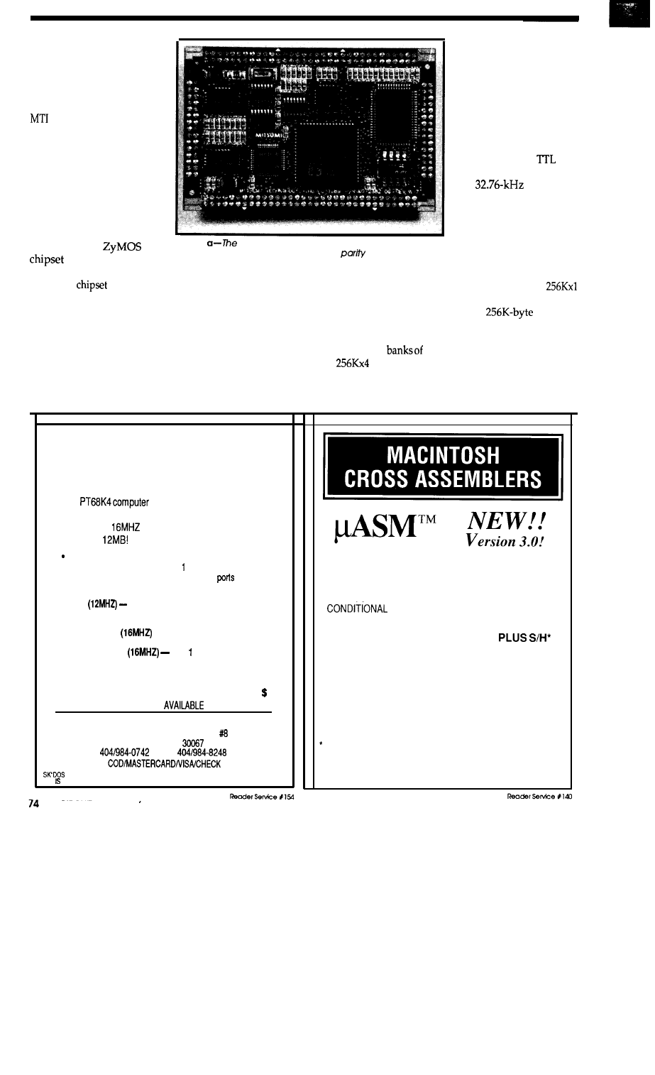
previous board space. Addi-
tional space is gained by us-
ing gate arrays.
Within three years of the
initial investigations of
manufacturing techniques,
released the “286 Micro-
engine” shown in Photos la
and lb. The Microengine
contains all the major com-
ponents of an 80286 mother-
board, including 512K of
DRAM, compressed into a 4
x 2.6-inch module. What’s
most interesting is that it is
totally manufactured in the
U.S. using a
AT
and Award’s AT
BIOS.
Although another
Photo 1
top side of the 286 Microenglne shows the 80286
processor, half of the ROM BIOS, DRAM
bits, and assorted
glue logic.
BIOS and
may be used in the future, the end prod-
uct will always be electrically compatible with the original
module.
Photo la shows the top surface of the 286 Microengine.
The 80286 CPU is mounted on the top side of the module.
It is the largest chip because it is used in its standard J-lead
package. To the right of the processor is the only other
component used in its original package: the digital delay
line. Above the delay line, in the upper right corner of the
board, is a custom VLSI
chip holding the odds and
ends logic of the system,
such as RAS and CAS
generation. It uses 0.040”
lead spacing. To the left of
this VLSI and above the
CPU is a standard surface
mount 512x8 PROM.
Three standard
sur-
face mount packages and
the
crystal for
the real-time clock func-
tion reside to the upper left
of the CPU. To the imme-
diate left of the CPU is one
of the BIOS ROMs
mounted in special pack-
aging with 0.033” lead
spacing. On the extreme left of the module are two
surface-mount DRAM memory devices. These are used as
the parity bits for the system’s two
banks of
DRAM.
Photo lb shows the bottom surface of the Micro-
engine. The two
DRAM are located on the far left.
Four
surface mount DRAM
S
comprise the 512K
bytes of
system memory. The second
BIOS ROM is the
upper chip located next to the DRAM
S
. The Award BIOS
16 MHZ
68000
SINGLE BOARD COMPUTER
The new
board has all the features of the K2
series plus extra benefits. It is available in 2 speeds- 12MHZ
and a super fast
-with increased memory capacity to
a maximum of
4 RS232 pork
l
Floppy disk controller
l
7
XT
expansion slot
l
Real-time clock
l
Memory expansion slot
l
2 Parallel
l
Optional operating systems
BASIC
KIT
4
layer board, processor, Humbug monitor,
4K SHAM, 2 serial ports
$220
K4 COMPLETE KIT
-with 512K of DRAM
$545
ASSEMBLED BOARD
with MB DRAM
$649
PROFESSIONAL OS9 with compiler:
only valid if purchased with board
$299
SK’DOS OPERATING SYSTEM:
60
COMPLETE INFORMATION
UPON REQUEST
PERIPHERAL TECHNOLOGY
1710 CUMBERLAND POINT DR.
MARIETTA, GA
l
FAX
IS A TRADEMARK FOR STAR-K SOFTWARE SYSTEMS
OS9 A TRADEMARK OF MICROWARE AND MOTOROLA
*TEXT EDITOR, CROSS ASSEMBLER, AND
COMMUNICATIONS FACILITY IN A COMPLETE
INTEGRATED DEVELOPMENT ENVIRONMENT
l
MACROS
l
ASSY
l
LOCAUAUTO LABELS
us
$149.95
l
SYMBOL TABLE CROSS REF
EACH
l
S
OR HEX FILE OUTPUT DOWNLOADS
TO MOST EPROM PROGRAMMERS
AVAILABLE FOR MOST 8-BIT MICROPROCES-
SORS. CALL OR WRITE FOR TECHNICAL
BULLETIN. 30 DAY MONEY BACK GUARANTEE.
MCIVIAE.
PER
SHIPMENT:
$4 CONTIGUOUS USA
$8.50 CANADA AK. HI
Micro Dialects, Inc.
DEPT. C, PO BOX 30014
CINCINNATI, OH 45230
$15 INTERNATIONAL
(513) 271-9100
CIRCUIT CELLAR INK
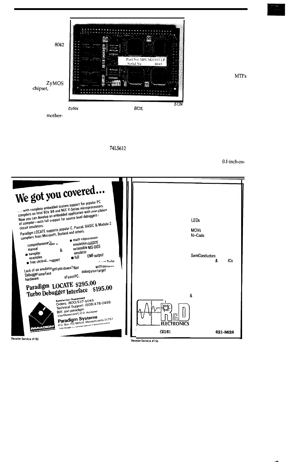
includes the setup rou-
tines necessary for config-
uring the system without
the need for a setup disk-
ette. Below the second
BIOS ROM is the
keyboard controller, again
in a special package to
reduce real estate. Next to
these devices are what has
to be the most impressive
job of packaging I’ve ever
seen.
T h e
POACH
which
consists of four VLSI
chips, contains the logic
functions of all the micro-
processor peripherals on
a standard AT
Photo 1 b--The
bottom side of the 286 Microengine contains
of DRAM. the second half of the
the keyboard control-
ler, and supporting POACH chips.
board. POACH 1 includes two 8259As (master and slave
programmable interrupt controllers), an 82284 (clock gen-
erator and ready interface), a 6818 (real-time clock), an
82288 (bus controller), plus miscellaneous control and
interface logic. POACH 2 includes an 8284A (clock genera-
tor), an 8254 (programmable interrupt timer), a
(memory mapper), two 8237s (byte and word DMA con-
trollers), plus refresh, timing, and parity check logic. The
two remaining POACH chips are identical. POACH 3 is a
buffered interface chip ca-
pable of driving the AT-style
expansion bus. One chip is
used for the data and associ-
ated control lines and the
other for the address and
associated control lines. On a
standard AT clone mother-
board, these four chips take
up about nine square inches
of board space. Using
special packaging, these chips
take up about two square
inches, mostly due to super
dense, 0.020” lead spacings.
The lead spacing (and space
between leads) here is 0.010”.
It gives me a sense of scale
when I remember that a hu-
man hair is about 0.001” in diameter.
The 286 Microengine has a total of 192 pins, giving the
designer access to all of the internal buses as well as the
connections needed for AT simulation, such as AT bus,
keyboard, speaker, and so on. The module can be soldered
directly to your embedded controller circuit board or
plugged in using two 2x15 and two 2x33 standard strip
sockets. This is the same spacing as standard
center square-pin headers. The entire module is enclosed
and
in-
,
startup code
,
Intel
a problem
option. N
OW
You can
from the comfort
R&D ELECTRONIC SURPLUS, INC.
Has been in business since 1946 selling NEW
surplus electronics and electromechanical parts.
Send for our FREE 40 page catalogue detailing:
Batteries
Cables
Capacitors
Lugs
Clocks
Connectors
Power Devices
Digital Timer/Controllers
Diodes
many Power Supplies
Displays
Relays
Enclosures
galore
Fans
Stepper Motors Driver
Fitters
Speakers
Heat-Shrinkable tubing
Many Switches
Heatsinks
Telephones and components
Transformers
Integrated Circuits
Ultrasonic Transducer Board
Lamps 8 Lights
Zeners
many more items
.
1224
Prospect Avenue
Playhouse Square
Cleveland, OH
44115
Telephone:
621-1121
l
Fax:
(216)
April/May 1990
7 5
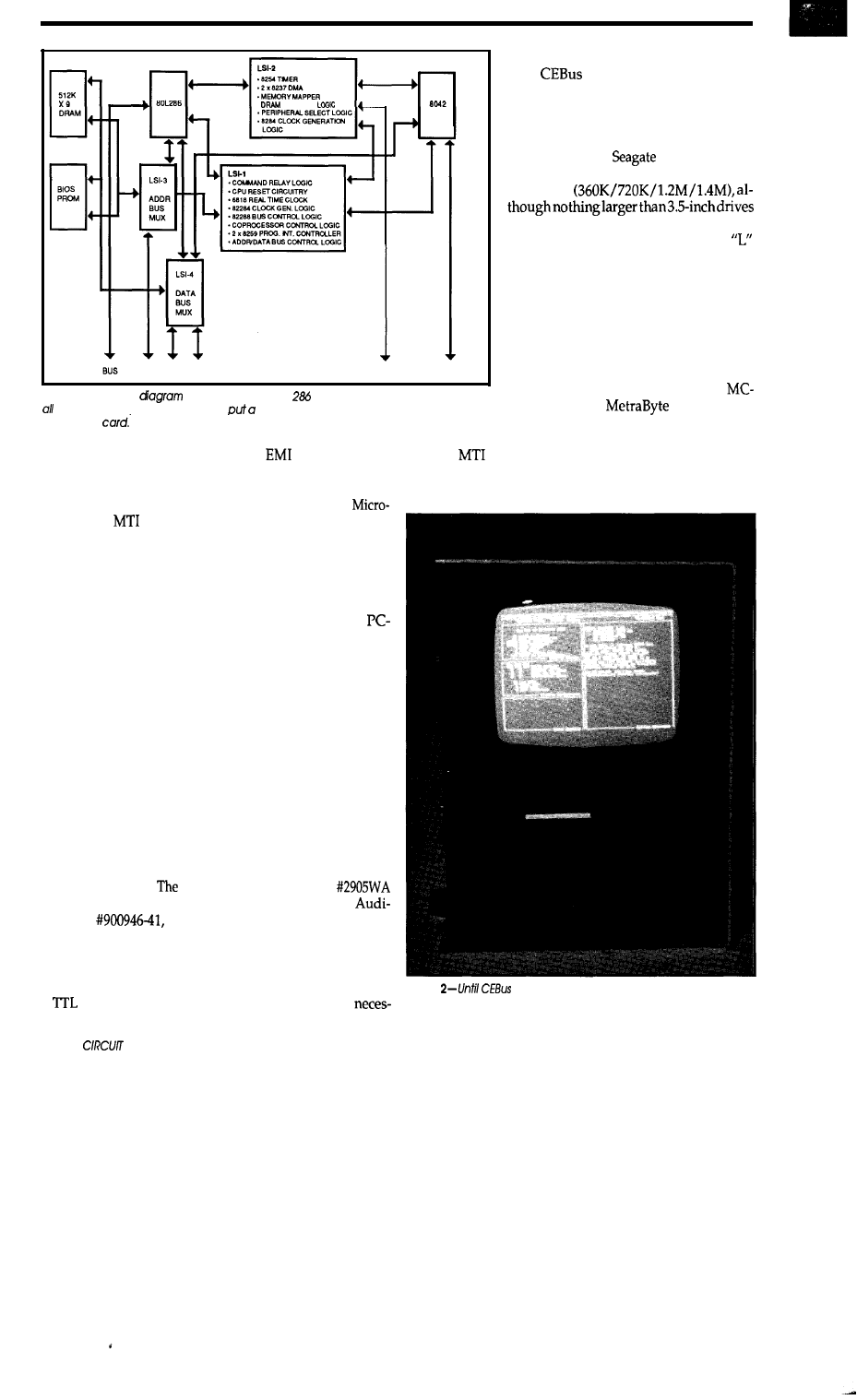
.
REFRESH
sary to run MC-Net. As it stands now,
until
becomes a bit more estab-
lished, the plan is to use MC-Net for the
Home Monitoring System.
One of the smallest implementations
of a combination floppy/hard disk con-
troller card is the
ST-02. This will
support two SCSI hard drives and two
floppies
fit here. The floppy drive is mounted to
the opposite side of the monitor’s
bracket, which allows the monitor and
floppy to be installed as one unit. The
bracket is made out of sheet aluminum
which makes a good electrical and me-
chanical connection with the enclosure,
eliminating
interference between the two
devices.
SPEAKER
KEYBOARD
Figure 1
-A block
of the Microengine
shows that the module contains
the necessary components to
complete AT motherboard on a half-size
expansion
The
Evaluation card completes the hardware
necessary for this transportable AT. Although it probably
won’t be moved, it will establish a firm base for the Home
Any serial port card would do as an
interface to an RS-485 adapter for
Net. However,
Corp. comes
in with one of the smallest serial port
cards that has RS-485 output.
BUS 80287 BUS
within a metal container to contain
and offer some
heatsinking to the 80286 processor. Figure 1 shows a block
diagram of the 286 Microengine.
To help engineers feel comfortable with the 286
engine, the
engineering team has a half-size Evalu-
ation Card. This card contains AT-bus edge connectors
and the necessary jumpers and clocks to simulate a com-
plete IO-MHz 512K l-wait-state AT motherboard. The
half-size card can drive an AT passive backplane just like
the full size OEM-286 processor board.
Applications for the 286 Microengine such as
based workstations, laboratory control, and data acquisi-
tion equipment will be springing up left and right. Mod-
ules containing other functions such as video, serial, and
parallel I/O are already under development. The 286
Microengine is competitively priced at $500 in single
quantities. The evaluation card adds an extra $100. The
286 Microengine consumes less than 5 watts at 5 volts and
its lower-power sibling uses less than 3 watts.
JUST THE RIGHT SIZE
As you can probably guess by now, I had an immedi-
ate application for the 286 Microengine. My choice of en-
closures and desire to include an internal monitor capable
of displaying EGA (for use with MC-Net; see Photo 2) de-
termined the need.
enclosure
is similar to the
from Integrand Research Corp. The display is an
otronics
a 5-inch 12-volt monitor. The moni-
tor is attached to an “L” bracket which bolts to the enclo-
sure where a disk drive would normally go. A standard
monochrome display card would drive the monitor fine,
but I had to use an EGA Wonder card because it can drive
a
monochrome monitor with the EGA video
76
CELLAR INK
Photo
becomes
a bit more established, the plan is
to use MC-Net for the Home Monitoring System.
Monitoring System. All of the half-size cards fit easily into
the old double disk drive enclosure. Bring on the carpen-
ters!
Now I will be able to run MC-Net and up to thirty-one
independent microcontroller nodes to implement the dis-
tributed Home Monitoring System. Or, let’s see, maybe
embed the 286 Microengine module as an RTC286 proces-
sor
board. This is like playing with building blocks all over
again!
Jeff Bachiochi (pronounced “BAH-key-AH-key”) is a member
of the
Circuit Cellar
staff.
His background includes work in
both the electronic engineering and manufacturingfields. In his spare
time,
his family, windsurfing, and pizza.
SOURCES
MC-Net
Enclosures
Micromint, Inc.
Integrand
4 Park St.
8620 Roosevelt Ave.
Vernon, CT 06066
Visalia, CA
(203)
(209) 651-1203
286
Microengine
Mitsumi Technology, Inc.
3295 Scott Blvd.
Santa Clara, CA
(800) 980-5400
Intel Literature
Dept. W-472
Santa Clara, CA
(800) 548-4725
RS-485 Serial Card
Corp.
440 Myles Standish Blvd.
MA 02780
(617)
ST-02 Hard Disk
Technology
920 Disc Drive
Valley, CA
(408)
Correction to “Prom the Bench”
“Building an LED
Moving Message Display”:
The following items are available from
Circuit Cellar Kits
P.O. Box 772
CT 06066
(203) 875.2751
1. Blank PC board, manual, and demo software on 5.25” 360K
PC-format disk. SD-1
2.
Sprague
driver chips. SD-2. . . . . . . .
3. Eight
red 5x8 LED array modules. SD-3
$50
please add shipping and handling in U.S.; $8 elsewhere.
IRS
219 Very Useful
220 Moderately Useful
221 Not Useful
MS-DOS EPROM
PROGRAMMING SYSTEM
NEEDS NO INTERNAL CARD
E P R O M S
2708
2564’
28256’
0742’
8744H’
‘Socket Adapter
Required
CONNECTS TO YOUR SYSTEM’S
SYSTEM SOFTWARE COMMANDS
.
PROGRAM EPROM(S) . SAVE EPROM S OR
FROM DISK FILE
BUFFER TO
.
. COPY EPROM S)
FILE INTO . PROGRAM EPROM(S)
ERASED
FROM BUFFER
. BUFFER EDITOR
INTO . COMPARE EPROM(S)
l
SELECT DEVICE TYPE
WITH BUFFER
. DEVICE CHECKSUM
BUFFER
HAS 18 BYTE
LEVELCOMMANDS FOR DETAILED OPERATIONS
S Y S T E M I N C L U D E S : P R O G R A M M I N G U N I T , P O W E R P A C K ,
C O N N E C T I N G C A B L E , O P E R A T I O N M A N U A L S O F T W A R E
$239
SOFTWARE AVAILABLE ON 3
OR 5
DISK
TO ORDER SEND CHECK. MONEY
OR CALL.
ANDRATECH
P.O. BOX 222
MILFORD, OHIO 45150
(513) 831-9708
GIVE A NEW DIMENSION TO PERSONAL COMPUTING
The
Kay
adds
command up to
keyboard
CAD, desktop
word
Spread sheet, game programs Fully
TSR and
less than
Instant response
and
accuracy
are
A
SPEECH RECORDING SOFTWARE
record
own speech. sound.
to
and
Kay
of a
card,
durable
headset,
and manual
Card any
and volume controlled output sockets High quality
and
ONLY $149.95
ONLY
FOR
TANDY
MODELS
SOFTWARE
TANDY BRAND
COMPLETE
ELECTAET MICROPHONE.
HOTLINE:
Monday-Friday.
5 PM
company checks. money orders,
accepted Personal
checks subject to 3 week
delay.
computer type and
5%“) when
Add
charge for
USA and Canada
contact
C
DAY MONEY BACK GUARANTEE IF NOT COMPLETELY SATISFIED ONE
YEAR WARRANTY ON HARDWARE.
CALL OR WRITE FOR FR
EE
PRODUCT CATALOG
SILICON
Whither Zilog?
UPDATE
Tom
A Roller Coaster on the Back of the
T
he heroes and villains of Silicon
Valley sometimes seem to be drawn
from the pages of a fairy tale.. a
soap opera. The only difference is the
source of the wealth that drives the
intrigue: Instead of the Golden Goose
or oil wells, it all starts with sand.
Zilog is just one story in the “Valley of
the Heart’s Delight.” But, over the
course of the company’s history we
get to see all the ups and downs that,
like earthquakes, make life around
here interesting.
IN THE BEGINNING
Zilog was founded in the mid-70s by a couple of Intel
guys
and Ralph
with a
better idea. They scratched together some venture capital,
made a foundry deal with Mostek and
was
born.
The chip was an instant hit. It combined the software
popularity of Intel’s 8080 with the
single-chip (no
clock generator, bus controller, or interrupt controller
required) advantages of Motorola’s 6800.
The company quickly followed on with the necessary
peripheral
SIO, PIO,CTC, and so on.
chips were
quick winners too. In fact, many who weren’t convinced
of the merits of
CPU
were often swayed by the ca-
pabilities of these peripheral
with which it worked. It
was a high-tech version of the proverbial tail wagging the
dog.
By the end of the
Zilog had become, along with
the much bigger Intel and Motorola, a powerhouse in the
microprocessor world.
CIRCUIT CELLAR INK
TROUBLE IN PARADISE
In retrospect, what befell Zilog in the early 1980s was
as much bad luck as a bad business decision. At the time,
despite the ongoing shipment of millions of 8-bit
Intel, Motorola, and Zilog all adopted the conventional
wisdom that the 8-bit world was dead, and that all existing
customers would quickly move to the new 16-bit chips (the
Motorola 68000 and Intel 8086). So began the
16-bit wars, a bitterly fought campaignbetween the giants.
Arguably, the 28000 was a good chip. Some say it lost
because it was a little late. Others point to the competitors’
marketing strength. I think the main problem was the
premise that everyone needed a
chip. In fact, until
the emergence of the PC and Mac, there was little
business for anybody.
Meanwhile, Zilog, under the tutelage of former inves-
tor and then owner Exxon, continued to lose focus (and
money) dabbling in everything from
to UNIX boxes.
Too late, the company tried to retrench in the 8-bit
world with the infamous
The chip was intended to
offer a high-performance alternative for existing
cus-
tomers. Unfortunately, management and personnel
over had reached the point that completing the design
became impossible. New engineers would leave even
before they got up to speed on what the previous engineer
had done. The final straw was the conclusion late in the
game that the
should be a CMOS, not NMOS part.
Back to the drawing board again.. .
The mid-80s were not a happy time at Zilog, with
semiconductor market slow-downs, little28000 business,
management turmoil, and the 2800 faux pas. If the story
stopped here, the title of this article might be “Remember
Zilog?”
Package
Lines
RAM
ROM
18 pins
14 lines
124 bytes
2K bytes
18 pins
14 lines
124 bytes
4K bytes
28 pins
24 lines
236 bytes
4K bytes
40
44 pins
32 lines
236 bytes
4K bytes
40
44 pins
32 lines
236 bytes
OK bytes
Figure
1
-2ilog’s
new CCP chips
in pin count, number
of lines. and amount of on-board memory.
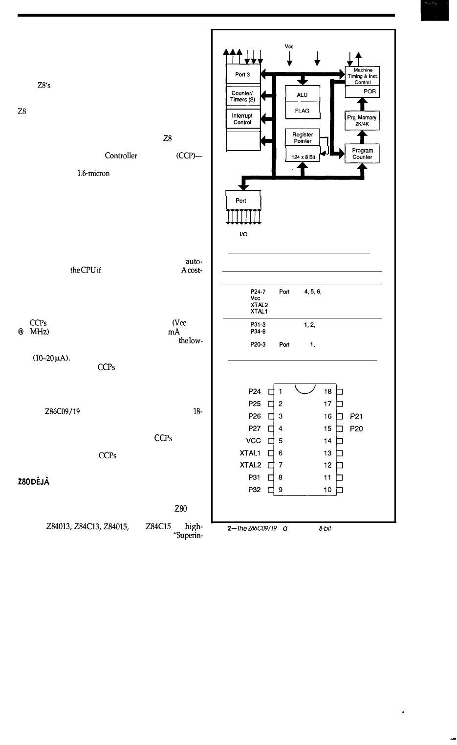
CONTROLLERS FOR THE MASSES
One semibright spot during the dark days was the
development of the Z8 8-bit single-chip computer. As so
often is the case for Zilog, the part itself was a competitive,
if not arguably superior, design. However, independent
of the
merits, Zilog had to swim upstream in the face
of the earlier, dominant Intel (8051) and Motorola (6801)
single-chips. To the company’s credit, they stuck with the
through the tough times and managed to build a
respectable business.
GND
XTAL
WDT,
Now, coincident with the departure of Exxon, the
newly “privatized” Zilog has combined the architec-
ture with their latest CMOS process to make a lineup of
controllers-the Consumer
Processors
that are notable for their low cost and minuscule power
consumption. The
CMOS process is a life saver
for Zilog, since it is apparent that one cannot hope to be a
major player in the embedded control market without its
low power and reliability.
2 Analog
Comparators
Register File
As shown in Figure 1, the differentiation between the
CCP family members is largely one of package size, ROM
(sorry, no EPROM yet), and RAM (more accurately, regis-
ter banks). Otherwise, all members share a common set of
I/O functions including two 8-bit counter/timers, two
analog comparator channels (two pins’ voltages com-
pared with a third), and a watchdog timer (which
maticallyresets
thingsdon’tseemright).
saving feature is the ability to choose between various
clock generation alternatives. Less expensive circuits in-
cluding RC, LC, and ceramic resonator may be used in-
stead of a crystal.
2
(Bit Programmable)
Pin Identification
Pin No.
Symbol
Function
Direction
The hallmark of CMOS is low power consumption and
the
fill the bill. Active power consumption
= 5V
8
for the lineup ranges from 10 to 20
(more
pins translates to more power), while thelowest of
power modes (STOP mode) consumes a thousand times
less
Carrying the virtues of CMOS to the
extreme, Zilog specs the
to operate with Vcc as low
as 2.75 V, which further cuts power consumption and is
great for battery-driven applications. However, check to
make sure the CCP low-Vcc I/O levels meet your needs.
l-4
2 pin
7
In/Output
5
Power Supply
Input
6
Crystal Oscillator Clock
output
7
Crystal Oscillator Clock
Input
8-10
11-13
14
GND
15-18
Port 3 pin
3
Fixed Input
Port 3 pin 4, 5, 6
Fixed Output
Ground
Input
2 pin 0,
2, 3
In/Output
I find especially intriguing the smallest family mem-
ber (the
shown in Figure 2). It comes in an
pin DIP! Best of all, the parts have tiny prices too: As low
as $1.50 in high volumes.
With this packaging and pricing, the
are truly
targeted at consumer markets (I mean toasters and toys).
Watch out 4-bitters, the
are breathing down your
neck.
VU...
P23
P22
GND
P36
P35
P34
P33
The latest Zilog offerings come full circle. Will they
bring the success of the heady days when the
was
king?
The
and
are
Figure
is complete
microcontroller in an
integration chips which combine, using Zilog’s
Id-pin DIP package.
April/May 1990
79
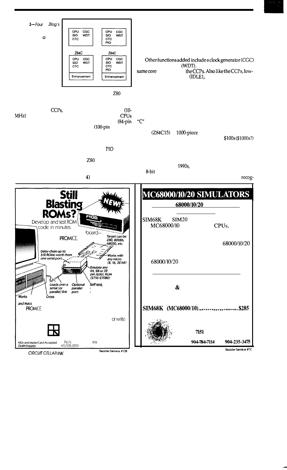
Figure
of
new
high-integration
chips include a whole lot
more
than just
micro-
processor.
284013
2840 15
13
15
tegration” standard cell design technology, the
CPU
with other standard peripheral functions. In addition to
the quality of their design, there’s good news in the fact
that they, like the
take advantage of Zilog’s fast
low-power CMOS process. Furthermore, the
exploit modern high pin-count packaging: PLCC
Plastic Leaded Chip Carrier) and QFP
Quad Flat
Pack).
The advanced design, manufacturing, and packaging
skills yield the lineup of chips shown in Figure 3. The four
new parts are permutations of two features:
(parallel
I/O in the “15s”) and enhancements (in the “Cs”).
Most of the core function-the
CPU, SIO, CTC,
and (for the 15s) PIO- work exactly the same as the earlier
nonintegrated (and very popular) chips of the same name.
In fact, the block diagram (Figure shows that the new
Superintegrated chips are just like multichip system de-
signs of old (note the on-chip address, data, and status/
control buses) shrunk onto a single die. Besides making
the
chip design easy, another advantage of this straightfor-
ward approach is that software drivers written for older
multichip systems port easily to
the newly integrated
equivalents.
and watchdog timer
The watchdog timer is the
thatisusedin
power operation modes
IDLE2, and STOP) are
provided.
The enhancements embodied in the “C” versions
encompass a variety of add-ons such as power-on reset,
wait state generator, two chip-select lines, and 32-bit CRC
hardware for the SIO. Together, they serve to slash TTL
from, and boost performance of, a minimal system. For
most applications, the enhancements probably justify the
version’s 20% higher asking price.
Speaking
of
prices, the family ranges from $9 (284013)
to $13
in
quantities. Not bad at all
considering that these days you can blow
for a RISC chip set and still end up short of cache!
BACK TO THE FUTURE...
As we enter the
Zilog’s sales level, profitability,
and
focus are much the same as 10 years ago. A key
difference is that now everyone, including Zilog,
without leaving your key
-with our
diagnose
up-load, down-load
hex or binary data
with most
development
PCs, Unix systems tools also
available
The
is an Intelligent Micro-Controller based
unit having optional Analysis Interface for Firmware
Debugging Support For more information, call
Grammar Engine, Inc.
3314
Morse Road
Columbus, Ohio 43231
6141471-1113
In
and Mountain
zones
Welcome
DEBUG
PROGRAMS
ON YOUR PC
and
are software simulations of
the
and MC68020
designed
to run on the IBM PC and compatibles with DOS
2.0 or higher. No additional hardware required.
They accept files generated by a
assembler. They are complete debugging tools,
providing access to registers, flags, and memory.
All
instructions, addressing modes
and condition codes are supported.
l
Load/Dump Facilities
l
Disassembler
l
Single-Step Fast Execution
l
Breakpoints
l
Interrupts
l
Terminal I/O Support
l
Symbolic Debugging
l
Execute Batch Files
SIM20 (MC68020) . . . . . . . . . . . . . . . . . . . . . . . . . . . . $345
BIG BANG SOFTWARE, INC.
W. Hwy.
98,
Suite
286
Panama City Beach, FL USA 32407
Phone
Fax
8 0
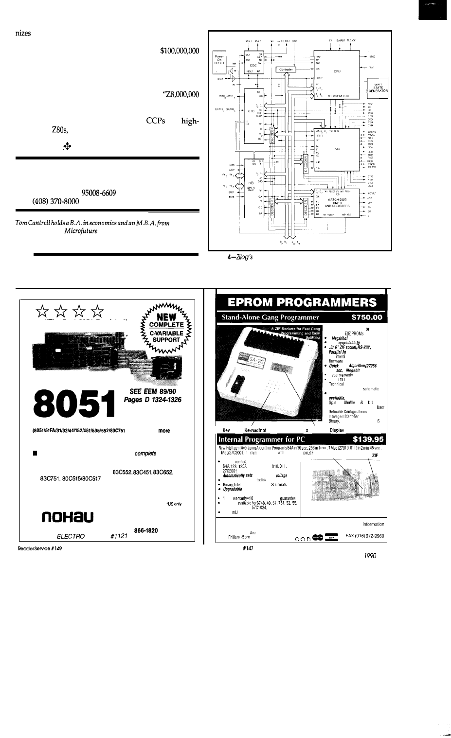
8 bits will live forever. Zilog gets another chance, as
if the ’80s were just a bad dream.
Make no mistake, it won’t be easy for a
company like Zilog to compete with today’s billion dollar
class giants. In particular, they must have the means and
the will to match the leaders’ R&D and manufacturing
investments. This time around, Zilog had better stay
focused on meat-and-potatoes products; no
targeted at the projected-to-be-exploding Personal Main-
frame market.”
Based on the strength of the new
and
integration
I say that Zilog will not only survive, but
has a good chance of making a
strong
comeback.
The story
isn’t over yet..
Contact
Zilog, Inc.
210 Hacienda Ave.
Campbell, CA
UCLA. He
owns and operates
Inc., and has been in Silicon Valley for
10 years involved in chip, board, and system design and marketing.
IRS
222 Very Useful
223 Moderately Useful
224 Not Useful
Figure
new Superintegrated chips are just like multichip
system designs of o/d shrunk onto a single die.
“The Best 8051 Emulator”
5 ft.
cable
PC
based emulators for the 8051 family
+ C M O S +
.
n PC plug-in boards or RS-232 box.
n Up to 20 MHz real-time emulation
Full Source-level Debugger including
C-variable
support.
n 48 bit wide, 16K deep trace, with “source line trace”
n “Bond-out” pods for 8051,
Prices: 32K Emulator 8031 $1790: 4K Trace $1495’
CALL OR WRITE FOR FREE DEMO DISK!
Ask
about our demo VIDEO
51
E. Campbell
Avenue
Campbell, CA 95008
C O R P O R A T I O N
FAX (408) 378-7969
(408)
SEE US AT
BOOTH
Completely stand-alone PC driven
Programs
1
DRAM
User
32
Megabit
and Out
32K
Flash EEPROM for easy
upgrades
Pulse
in 5
1
in 17 sec.)
2
Made S A
support by phone
Complete manual and
Single
Sock.9 Programmer also
$550.00
and
16
32
100 User Definable Macros 10
Intel Hex. and Motorola
20
Tactile
membrane)
20 4 Line
LCD
2
5
Internal card
external 40
Reads,
and programs 2716. 32, 32A. 64
256 512. 513.
301.
MCM 66764 2532
2 ft. Cable
40 pin
l
programming
Load and save buffer
Hex. and Motorola
lo 32 Meg EPROMs
l
No personality modules required
year
day money back
Adapters
TMS 7742.27210,
and memory cards
Made S A
NEEDHAM’S ELECTRONICS
Call
for more
4539 Orange Grove
*Sacramento. CA 95841
(916)
924-8037
M o n
PST
Reader Service
April/May
8 1
TIME
Excerpts from fhe
BBS
The Circuit Cellar BBS
bps
24 hours/7 days a week
8 7 1988
Four Incoming Lines
Vernon, Connecticut
Conducted by
We
have just one message thread this issue, so we’ll make
it a good one. Telephone circuits always seem to be
popular, and detecting call-progress tones is something
many applications require. There are numerous methods
that can be used to accomplish the goal, some better than
others.
From: DAWN R. BANKS To: ALL USERS
I’ve been trying to put together a circuit to do telephone call
progress monitoring. So far, I’ve bought a
chip at
the local Radio Shack, and that gives me digits. Next, I wired up
four 567s to give me dial tone, ringback, and busy. After this, I
start running down a
First, I see that if I want to detect
that loud “you left the phone off hook” noise, I’m going to have
to detect four simultaneous frequencies, which don’t seem to
overlap anywhere with those that I’m already looking for. After
that, I also find that if I want to listen for that “bodo-weep” for
an out-of-service phone number, I’m running into still more
frequencies to detect.
Before I get done with this, I can see having a whole room full of
each detecting one of the frequencies, and each incorrectly
detecting two or three of the others. The question that this leads
up to is: Is there really any better way of doing this? Is there some
off-the-shelf
that
adapt to myneeds,oram
I completely out of luck here? I would happily accept any other
constructive suggestions, including those that indicate that I’m
wasting my time completely. Keep it simple, because I’m not
really a hardware type, and this project is just me pretending that
I am. Thanks.
From: NATHAN ENGLE To: DAWN R. BANKS
Call progress is one of those sorts of things that gets harder to do
as your requirements get closer to never giving you an error.
Part of the problem if you’re trying to design a product that is
going to be sold all over the place know you’re not, but just bear
with me) you find that
central offices tend to use a very wide
variety
of cadences, and so on for different call progress tones. So
trying to squeeze that last
error condition out of
your design can be really hard.
82
CIRCUIT CELLAR INK
One tactic that you might want to consider is to
from the
idea of trying to detect the “phone left off hook” tone, and just use
a timer to hang up the phone after a given wait. I have to admit
that it isn’t a lot of good if you’re doing something like an
automated telemarketing box that has to know when the dis-
gusted party at the other end of the line has cut your sales pitch.
From: DAVE EWEN To: DAWN R. BANKS
If this system is based on a PC or something with computational
ability, you might consider an ADC to sample the tones and then
take the data and perform an
to convert to the frequency
domain.
From: DAWN R. BANKS To: NATHAN ENGLE
Thanks for the ideas. Yes, it will be connected to something with
some computing power (a
so the ADC is a point worth
considering.
Question: Am I going to get into some kind of hairy
when
I’m detecting something that’s more than one tone (such as
DTMF, dial tone, etc.)? The next question I have concerns call
completion; that is, what do I listen for? Do I get a “wink” on the
phone line, or is there something more involved? As a related
question, how do I differentiate this “call disconnection” signal
from the “call waiting” signal? (I ask this because other devices,
such as phone answering machines and other RS boxes, seem to
have difficulty with this distinction.)
From this, I guess I’ll just stick with the basic four-tone decode
that gives me dial tone, ringback, and busy. I should probably see
a dial tone before I see the “phone off hook” noise anyway.
Thanks again (suggestions still happily accepted).
From: KEN DAVIDSON To: DAWN R. BANKS
Or you could just use a call-progress-tone detector chip. Teltone
makes a few (M-980, M-981, M-982, and M-984). Silicon Systems
second sources most of them as the SSI 980, SSI 981, and SSI 982.
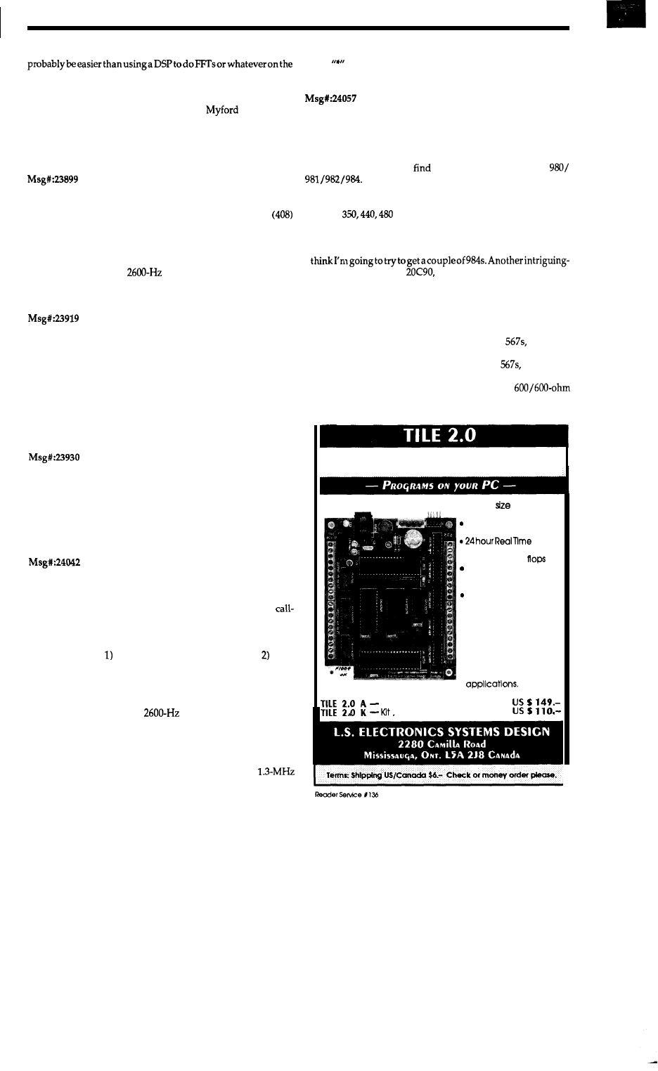
Contact the companies and get data for the chips. I think it’ll
incoming signal...
Teltone Corp.
P.O. Box 657
10801120th Ave. N.E.
Kirkland, WA 98033-0657
(206) 827-9626
Silicon Systems, Inc.
14351
Rd.
Tustin, CA 92680
(714) 731-7110
From: BOB PADDOCK To: DAWN R. BANKS
Mite1 also makes call progress parts. Try (619) 2763421,
249-2111, or (312) 574-3930, whichever is closer.
If you’re trying to find out if the other end of a long-distance call
has hung up, maybe you can detect the short ‘beep“ you hear at
the end of the call. It is a
tone, called “line idle.” Problem
would be to not have voice detected as this tone.
From: DAWN R. BANKS To: KEN DAVIDSON
Thanks. This is exactly what I was hoping someone would
suggest (just didn’t know what to ask for).
Since my sources here in New England for electronic parts seem
to be a bit limited, any suggestions as to where I could obtain a
couple of these (assuming that I’ve successfully laid hands on the
documentation)? Mail order sources?
From: KEN DAVIDSON To: DAWN R. BANKS
It’s not likely you’ll find either Teltone, SSI, or Mite1 at any
surplus mail order place. About the only way to proceed is to
contact each company directly and find out where the nearest
distributor is, then ask them about getting some.
From: ERIC BOHLMAN To: DAWN R. BANKS
Teltone is pretty good about giving out engineering samples; in
fact, I was able to get an M-982, which is a pretty good
progress detector chip. I think they run about $12 in small
quantities.
Signals to indicate when a call has been connected and when
the party on the other end has hung up are far from standard.
Folk wisdom says that the polarity of your line reverses briefly
when the other
party
answers;
my experience has been that that’s
true only if you’re on a step-by-step exchange. You also can’t
count on getting a burst of
at the end of a connection,
since that’s an artifact of using trunks with SF signalling, and not
all connections are routed over such trunks.
One further note: if you’re just interested in detecting dial tone,
try using a DTMF detector like the SSI 202, but use a
crystal instead of the usual 3.58. Dial tone should then show up
as the
output from the detector.
From: DAWN R. BANKS To: ERIC BOHLMAN
Thanks for the input. I was just looking at an “IC Master,” which
seems to be the only reference source I can find for any of this
stuff. Obviously, I can get this information from the manufac-
turer, but I was hoping to
the differences between the
From the sound of things, the 982 does pretty
much what my set of four 567s does, albeit in a much smaller
package, and probably better. (That is, the IC Master said it
detected
and 620.) The short description for the 984
said it also detected other frequencies, although there wasn’t any
description of which.
I
looking chip is the SSI
which purports to be a DTMF
transceiver with call progress indication. Again, this is all I know
about the chip.
The most recent reason I’m so hot on using one of these chips is
that although
I can detect most of what’s advertised with my little
breadboard of a DTMF decoder and those four
I can hear
one of the chip’s oscillators on the phone line it’s plugged into. I
didn’t start hearing it until I started adding the
so I suspect
it’s just shoddy design on my part, and not the SSI 202 DTMF
decoder chip. I have the phone line isolated with a
transformer (with DC-blocking capacitor on input, and the 567s
8031
B A S E D
PROGRAMMABLE CONTROLLER
l
Board
4.5 x 5.5
l
Requires 5 V dc supply
20 inputs, 16 outputs
. 24 virtual bits
Clock
with 8 timers
l
8 set/reset flip
4 timing pulses
. 8 one-shot timers
l
stack architecture
2 file spaces up to 256
Instructions each
. Uses PC for operator
interface
. Program storage
on disk
. English like commands
. Easy to program
l
Ideal for testing, moni-
toring and automation
Board and Manual
all parts and manual
April/May 1990 83
are behind a
cap on the other side). I’m hoping that a chip
designed for this isn’t going to bother me with as many of these
problems.
As for call termination status: I’m not really looking for a general
solution here that’11 work everywhere. In fact, all I’m interested
in is something that’11 work on the phone exchange here at home.
To that end, I’ve been meaning to put a scope on the phone line
and watch what happens at the end of a phone call.
From: ERIC BOHLMAN To: DAWN R. BANKS
You ought to get hold of the databooks from Silicon Systems and
Teltone. The SSI
has
a limited call progress detector;
it just gives you an output when
energy is present in the
to
640-Hz band. I’m not quite
sure of
the
differences between
the
981 and M-982; they seem to be pin compatible. The 984 is
optimized for detecting the special tones; it can’t discriminate
between dial tone, ringback, and busy. Oh, I just found out the
difference between the 981 and 982: the 982 can detect 620 Hz,
whereas the 981 replaces that channel with 400 Hz.
From: DAWN R. BANKS To: ERIC BOHLMAN
Well, it would seem that I’m not going to find a one-stop solution.
I had already found the differencesbetween
and 982.
I was kind of hoping that the 984 would be a
of the 982,
but I guessed wrong. Oh well...982 it is, I suppose.
Total control
with
for Programming Professionals:
an expanding family of compatible,
performance compilers for microcomputers
For Development:
Interactive Forth-83 Interpreter/Compilers
for MS-DOS,
and the 80386
l
and
implementations
l
Full screen editor and assembler
l
Uses standard operating system files
l
500 page manual written in plain English
l
Support
for
point, native code generation
For Applications:
Forth-83 Metacompiler
l
Unique table-driven multi-pass Forth compiler
l
Compiles compact
or disk-based applications
l
Excellent error handling
l
Produces headerless code, compiles from intermediate states,
and performs conditional compilation
l
Cross-compiles to
8086, 68000, 6502,
V25, RTX-2000
l
No license fee or royalty for compiled applications
Laboratory Microsystems Incorporated
Office Box 10430, Marina
Cd 90295
Phone Credit Card Orders to: (213)
FAX: (273)
The Circuit Cellar BBS runs on a IO-MHz Micromint
OEM-286 IBM PC/AT-compatible computer using the
version
of
The Bread Board System
and currently has four modems connected. We
invite you to call and exchange ideas with other Circuit
Cellar readers. It is available 24 hours a day and can be
reached at
871-l 988. Set your modem for 8 data bits,
stop bit, and either
or 2400 bps.
IRS
225
Very Useful
226
Moderately Useful
227 Not Useful
SOFTWARE and BBS AVAILABLE on DISK
of charge from the Circuit Cellar BBS. For those unable to download files, they are
also available on one
5.25” IBM PC-format disk for only $12.
Circuit Cellar BBS on Disk
Every month, hundreds of information-filled messages are posted on the Circuit
Cellar
BBS by people from all walks of life. For those who can’t log on as often as
they’d like, the text of the public message areas is available on disk in two-month
installments. Each installment
on three
5.25” IBM PC-format disks
and costs just $15. The installment for this issue of INK (April/May 1990) includes
all public messages posted during January and
To order either Software on Disk or Circuit Cellar BBS on Disk, send check or
money order to:
Circuit Cellar INK Software (or BBS) on Disk
P.O. Box
772, Vernon,
CT
06066
or use your
or Visa and call (203)
Be sure to specify the
issue number of each disk you order.
ARE YOU FED UP?
l
Simulation too w?
Target
hardware not
l
Write your
68000
program on any
PC/AT or Clone.
l
Cross assemble with the included support software.
l
Download at high speed through the I/O channel.
l
cost
l
ACIA allows two-terminal
debugging of
complex code
l
Use
two or more boards for multiprocessing
(software support available)
l
Uses
8
MHz 68008, 64K
SRAM; three
sockets for up to 128K of EPROMs.
with Absolute XASM
. . . . . . . . . . . . . . . . . . . . . . .
Debug EPROM . . . . . . . . . . . . . . . . . . . . . . . . . . . . . . . . . . . . . . . . . $75
C Cross Compiler . . . . . . . . . . . . . . . . . . . . . . . . . . . . . . . . . . . . . . . . . . . . . . . . . $395
68000 Linking Cross Assembler . . . . . . . . . . . . . . . . . . . . . . . . . .
$175
I
.
or
SO SOUTH
STREET,
PA 17837
717-523-0777
CELLAR INK
CEBus Comes One Step
Closer to Reality
DOMESTIC
AUTOMATION
Ken Davidson
A
nyone following the home automation
dustry has no doubt heard of CEBus. Well, after over
five years of work, we’re finally about to see
thing official come down the line. I recently got
back from the November EIA/CEG CEBus
mittee meeting in Sunnyvale and have some
interesting events to report.
First of all, we should dispense with all
thistalkabout
Automation Standard” (as it will
always correctly be referred to)
will be known to the public at
large as
(assuming it
gets through the trade-
mark search; the backup
is “Harmonet”). After
extensive research by
both EIA and an out-
side consultant
ducedalistofadozen
o r s o p o t e n t i a l
names for the stan-
dard, EIA settled
on this one. No, it
doesn’t stand for
physical layer details.
groups
exist for the other physical media
plus conformance, publicity, and so
In charge of all the working
groups is the Technical Steering
Committee
The TSC
sees the entire
ing process, sets
policy guidelines,
and has the final say in any
ter regarding the
Once a working group has a
portion of the specification that
anything. It’s easy to say, conveys an aura of high tech
with the
at the end, and should be just what the
marketing boys are looking for. Please forgive me if I
continue to refer to the standard as CEBus for the time
being.
they feel is ready for public comment, they present it to the
TSC for approval. Once approved, the proposed
is
published and goes out for a comment period. During the
comment period, anybody who would like to review the
proposed
and make comments on it is free to do so.
The intention is to get the
into the hands of engineers
who work for companies that are members of the commit-
tee, but haven’t necessarily been able to attend
meetings.
However, anybody who takes the initiative to obtain a
copy of the
may comment. Positive comments are
always welcome, but don’t affect any final decisions.
Negative comments must be accompanied by supporting
arguments, and may also include altema tive ideas.
tivecommentswithoutsupportingargumentsareignored.
Each comment is acknowl-
edged by the
though
they are under no obligation
to take action on the com-
ment.
The long-anticipated event, though, was the official
release of several portions of the CEBus specification for
comment. Before getting into exactly what was released,
let me explain
procedure for releasing a specifica-
tion,
EIA STANDARDS MAKING
When the committee was first put together, several
working groups were established to hammer out the de-
tails of individual portions of the
For example, the
language Working Group
is responsible for the
upper network layers including CAL. The Power Line
Working Group
is responsible for the power line
Once all comments have
been received and acknowl-
edged,
any significant
changes that the
makes
to the
as a result of the
comments are sent out for
comment (rather than the
whole
This cycle con-
tinues until everyone is
happy
with thespecification.
At that point, the document
becomes a interim EIA
April/May
that companies can be comfortable in using to put
together product.
At the November committee meeting, the LWG and
PLWG hammered out several last minute details and
submitted the power line physical layer
the data
link layer (which is made up of the node medium access
control
[MAC] and the node logical link control
the node network layer, the node applica-
tion layer, and CAL to the
for approval. The
gave
such approval, so the power line physical layer and all the
other network layers have gone out for comment.
The current schedule calls for the initial comment
to close at the end of April, at which time the
committee will take a careful look at all the comments and
make any necessary changes.
Once the CEBus
has graduated from being a
proposed
to an interim
it will be known as
Once
adopted as an official specification, it will be
To get your own copy of the proposed CEBus specifi-
cation and have the opportunity to influence the future of
homeautomation, see theinformationboxat
of the
column. EIA is encouraging engineers to scrutinize the
proposed
and make constructive comments. I’m sure
they’d love to hear from you.
MORE CEBUS HARDWARE
I described in my CEBus overview ar-
ticle two hardware implementations
of CEBus that are available for
neersinterested in
embedding CEBus
in an upcoming product. Texas In-
struments has developed a pair of
chips that make implementing a
CEBus interface much easier and have a new-generation
evaluation board available that uses those chips. The
(I talked about the
in the overview ar-
ticle) uses
new
CEBus controller chip and
the
powerline modem chip to implement a
complete
CEBus interface that can be attached to
switches, lights, or a processor for smarter control. They
also have software available that allowsmonitoringof net-
work traffic, and sending and receiving of packets. Con-
tact TI for more information.
OVERSEAS
In developments overseas, the Eu-
ropean community is about to officially
announce
to the world.
is an
international standard for control and
communication for audio/video devices.
Expect to see stereos and VCRs starting
to show up in the trade shows in the
months ahead sporting
interfaces.
WRAP UP
Electronics Show
Though I
didn’t see as much as I’d hoped aimed
at the home control market, there was
enough to be interesting. In the com-
ing months, I’ll be going into more
detail about what I saw and where the
market seems to be headed. And, of course, as soon as we
get our hands on some hardware, especially actual chips,
we’ll be putting it through its paces and showing it
in these pages. Stay tuned...+
EIA CEBus
EIA Standards Sales Dept.
1722 Eye St. NW
Washington, DC 20006
SEM300
Texas Instruments, Inc.
Box 809066
Dallas, TX 753804957
Ken Davidsonis themanagingeditoranda
M.S. in computer
science
from
Rensselaer Polytechnic Institute.
IRS
228 Very Useful
229 Moderately Useful
230 Not Useful
Steve
has assembled a team of engineers,
designers, and programmers to produce the products
that have made Circuit Cellar famous. Now you can put
the Ciarcia team to work for you.
Steve Ciarcia and his staff have designed products
ranging from communications and networking compo-
nents to multiprocessing computers. Current capabili-
ties include every phase of design and production, from
initialconcept through packaging
of
the finished
product.
Whether you need an on-time solution for a unique
problem, complete support for a startup venture, or
experienced design consulting for a Fortune 500 com-
pany, the Ciarcia Design Works stand ready to
you.
Remember.. .a Ciarcia design works!
INK

The Home Computer
Revolution is Over
O W N
INK
remember the early days of The Revolution. There
weren’t many small computer systems, there were even
fewer magazines about them, but there was an almost
evangelical fervor about how these “toy” computers were
going to change our lives. Of course, in the years since
then, the computers have changed, and our expectations
have changed along with them. I’m not going to go into
what computers have done for our business lives, but I
think it’s time for a quick peek at the corpse-littered trail of
the home computer market.
In the late ’70s and early
you couldn’t read a
technology-oriented magazine or newspaper article with-
out seeing several paragraphs about how every home
would soon have a personal computer occupying a posi-
tion of honor and importance. Dad would bring home
work from the office and keep the family checkbook in
order, Mom would search a voluminous recipe database
and work budgeting miracles to rival the Pentagon’s, and
little Buffy would churn out Ph.D.-level term papers and
learn with joy, havingreplaced
with the
friendly warm glow of her CRT.
Now, we know that, with the possible exception of
both Mom and Dad bringing home work from the office,
very little of that scenario has come to pass. Most people
don’t want to complicate their lives with a new system. A
four-function calculator provides as much computing
horsepower as most folks can cope with, and costs about
the same as a box of Twinkies. Generally, the media and
general population have written off the home computer
along with the home
and personal hovercraft.
It’s not that
best
of American industry didn’t try to
make the home computer as much a part of the residential
landscape as the television. Apple, IBM, TI, Sinclair,
Commodore, Coleco, and others gave it their best shots,
but came away without much to show for their efforts
(unless you count excess inventory tax credits as “some-
thing to show.” Listen to any computer industry pundit
and they’ll tell you: Home computers are about as com-
mon as the black-footed ferret. The only problem with the
industrygurusisthat they’reabsolutely,irrefutablywrong.
Whileeveryone had theirattentionglued to the “glam-
our toy” versions of home computers, a serious clandes-
tine movement was beginning. At the same time that
families across America were just saying no to computers,
CIRCUIT CELLAR INK
they were embracing microwave ovens like long-lost rela-
tives. Nearly all of
the microwave
ovens carried microcon-
trollers or microprocessors into the homes of the heart-
land. Meanwhile, the energy crisis was making more
people think about improving their home climate control
system. In most cases, better control meant a microproces-
sor of some flavor. The tide swept onward, with VCRs,
televisions, stereos, telephones, coffee makers, and other
common household items flooding American homes with
little computers. Ever hear of Nintendo? Yes, it’s a
rhetorical question. Every time a wild-eyed adolescent
plugs into the Super Mario Brothers, he or she is booting
a computer.
Now that most people are more comfortable with
digital electronic technology, marketers are starting
oh, so cautiously-introduce computer-like appliances. In
Japan, there are keyboards and storage devices that plug
into Nintendo systems. Several digital televisions would
need a minimum of add-ons to start functioning as
quality data terminals. (If you have trouble with that
concept, just remind yourself that Sears owns a large
chunk of Prodigy.) More than all of that, however, the
trend-watchers are telling us that “home offices,” com-
plete with computer, fax machine, photocopier, and shred-
der, are going to be all the rage in the 1990s.
Thesimpletruthis that, while weal1 hadourhandsfull
of microwave popcorn, the “home computer revolution”
was fought and won by microprocessors and embedded
microcontrollers. The home office, stuffed to the gills with
computing and communications gear, wouldn’t be pos-
sible if millions of people had not become comfortable
with the idea of computers through microwaves, video
games, and VCRs. The barricades are down: It’s time to
move forward.
Now if we can just figure out a way to start sneaking
home robotics in though the back door..
Wyszukiwarka
Podobne podstrony:
circuit cellar1991 04,05
circuit cellar1992 04,05
circuit cellar1991 04,05
circuit cellar1992 04,05
circuit cellar1991 04,05
circuit cellar1990 04,05
circuit cellar1996 04
circuit cellar2001 04
circuit cellar2002 04
circuit cellar1995 04
circuit cellar1994 04
circuit cellar2004 04
circuit cellar2000 04
circuit cellar2003 04
circuit cellar1997 04
circuit cellar1996 04
circuit cellar2001 04
circuit cellar1996 04
circuit cellar1995 04
więcej podobnych podstron