IEEE TRANSACTIONS ON EDUCATION, VOL. 44, NO. 2, MAY 2001
165
Using MathCad in Understanding the Induction
Motor Characteristics
Khalid A. Nigim, Member, IEEE, and Ronald R. DeLyser, Senior Member, IEEE
Abstract—Computer-aided
multimedia
education
is
in-
creasingly popular within the classroom and laboratory. The
applications of market-ready mathematical and database pro-
gramming software for teaching engineering course outline is
well appreciated. This article shows how MathCad can be used to
introduce electrical machine characteristics simulated at different
possible control modes. The undergraduate students require
minimum knowledge of a programming language. The examples
presented in the article show how MathCad software can be used
to simplify some of the characteristics of the three-phase and
one-phase induction machine. The result of introducing math
software as a teaching tool at the third- and fourth-year level have
been accepted and are now used as part of the practical sessions
for the electrical machine and other credited courses at Birzeit
University, West Bank and Gaza in the Palestine.
Index Terms—Computer application in education, electric ma-
chines, MathCad application.
I. I
NTRODUCTION
C
URRENT mathematics software packages are equipped
with highly interactive displays, signal processing, proto-
typing, three–dimensional (3-D) plots,
–
graphs, word pro-
cessing and data layering to enable rapid interpretation and pre-
sentation of results and trends. The direct use of this type of
software is a major advancement in simplifying simulation pro-
cedures for many practicing engineers as well as for undergrad-
uate engineering students [1]–[3]. The integration of the motor
and electronics to adjust the inherent motor characteristics make
it difficult for the tutor to simplify and present the subject to un-
dergraduates without the assistance of some kind of simulation
tools. A successful simulation tool requires time, energy, and
skills in computing languages and general knowledge of the op-
erational characteristics of the electrical machine and its perfor-
mance.
To keep sustainable interest in the education process and
with many students enrolling in colleges with some computer
literacy, it is essential to reinforce the engineering education
curriculum with computer-aided teaching tools that are interac-
tive as well as educational. For these reasons a mathematical
package was introduced to initiate the changes in teaching
methodology at the author’s engineering college.
Manuscript received October 20, 1999; revised October 31, 2000.
K. A. Nigim is with Birzeit University, Electrical Engineering Department,
Birzeit, Palestine (e-mail: kldngm@excite.com).
R. R. DeLyser is with the Department of Natural Science, Mathematics
and Engineering, University of Denver, Denver, CO 80210 USA(e-mail:
rdelyzer@du.com).
Publisher Item Identifier S 0018-9359(01)01769-1.
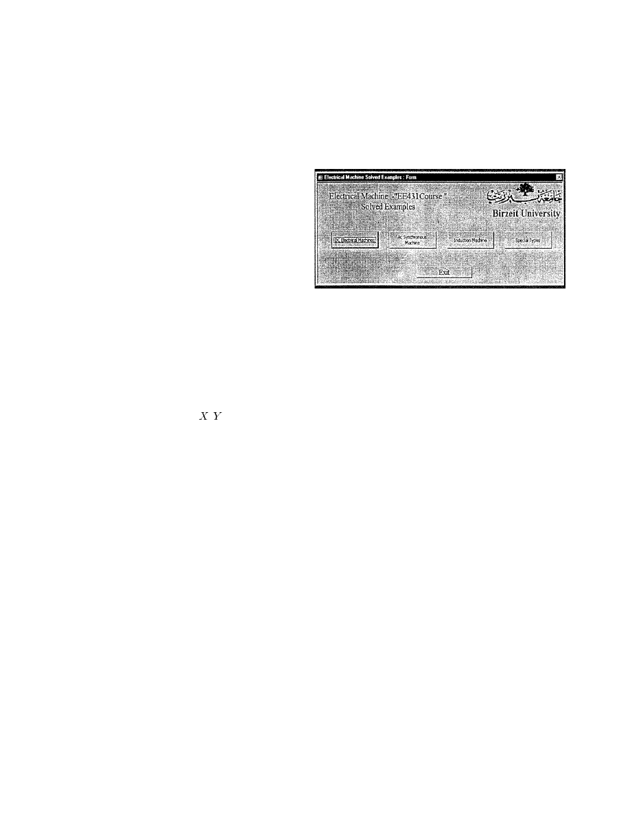
Fig. 1.
The electronic handbook main menu designed with MS-Access tool.
II. M
ATH
S
OFTWARE AS AN
E
DUCATIONAL
T
OOL
F
OR
E
LECTRIC
M
ACHINE
C
ASES
The early versions of software to simulate motor performance
are presented in references [4]–[6]. The work introduces the ba-
sics of teaching electric machines using programmable routines
and was dedicated to a few aspects of the phenomena of electric
machines using the DOS environment and interactive graphics
software. In early 1994, the electrical engineering department
at Birzeit University used MathCad in the teaching classrooms
and PC laboratory on a trial basis in order to enhance interactive
teaching and learning. Equation solution of the electrical motor
and drives performance is straightforward once the basic fea-
tures of MathCad software are learned [7].
Of course, MathCad software is widely used for many sci-
entific and engineering principles and is not the only package
available [8], [9]. It is easy to use and has many built-in functions
that facilitate its use in many textbook applications. The next
sections will demonstrate the versatility of adopting MathCad
in evaluating the characteristics of three-phase and one-phase
induction motors under variable input conditions. Study cases
1 and 2 present the steady state characteristics of the three-
phase induction motor under varying input conditions, while
case 3 presents the one-phase motor characteristics. The exam-
ples were presented to and accessed by the student through the
creation of an interactive electronic handbook page created by
MS Access software as seen in Figs. 1 and 2. The multiple-
choice menu given to the student is used to navigate through
solved examples as the syllabus developed.
A. The Presentation of the Electric Motor Characteristics by
MathCad
In electrical motors, the electrical energy input and the me-
chanical energy output can be presented in mathematical form,
after presenting the physical operation of the motor with the
equivalent electric circuit shown in Fig. 3. The electric circuit
0018–9359/01$10.00 © 2001 IEEE
166
IEEE TRANSACTIONS ON EDUCATION, VOL. 44, NO. 2, MAY 2001
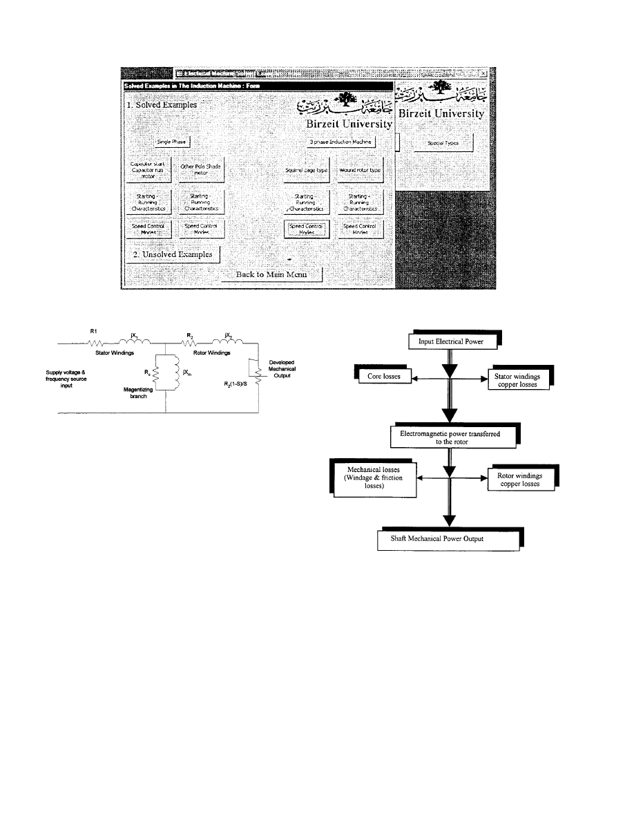
Fig. 2.
MathCad induction motor solved examples menu.
Fig. 3.
The three-phase induction motor equivalent circuit.
is used to facilitate the calculation of the current once the values
of the resistive and inductive motor windings components are
given at the base frequency and supply voltage. The values could
be evaluated experimentally by conducting the running light
(no-load) and locked rotor tests on the motor if that is possible;
otherwise, the manufacturer should be contacted for the infor-
mation.
The power flow, shown in Fig. 4, within the motor is tracked
by balancing the input and the output taking into account the
heat and magnetic power losses. The losses are quantified by
performing several standard tests on the motor. The current
flowing in the motor can be calculated using the equivalent cir-
cuit representing the motor physical elements. The steady-state
developed torque and power that are a function of the motor
current and speed are then evaluated and plotted to reveal the
motor characteristics. The expected efficiency of those par-
ticular parameters can also be plotted. Almost every textbook
presents the induction motor by its per phase equivalent circuit
and shows how steady-state current and power are estimated.
In many cases, the iron and mechanical losses are ignored to
simplify the procedures.
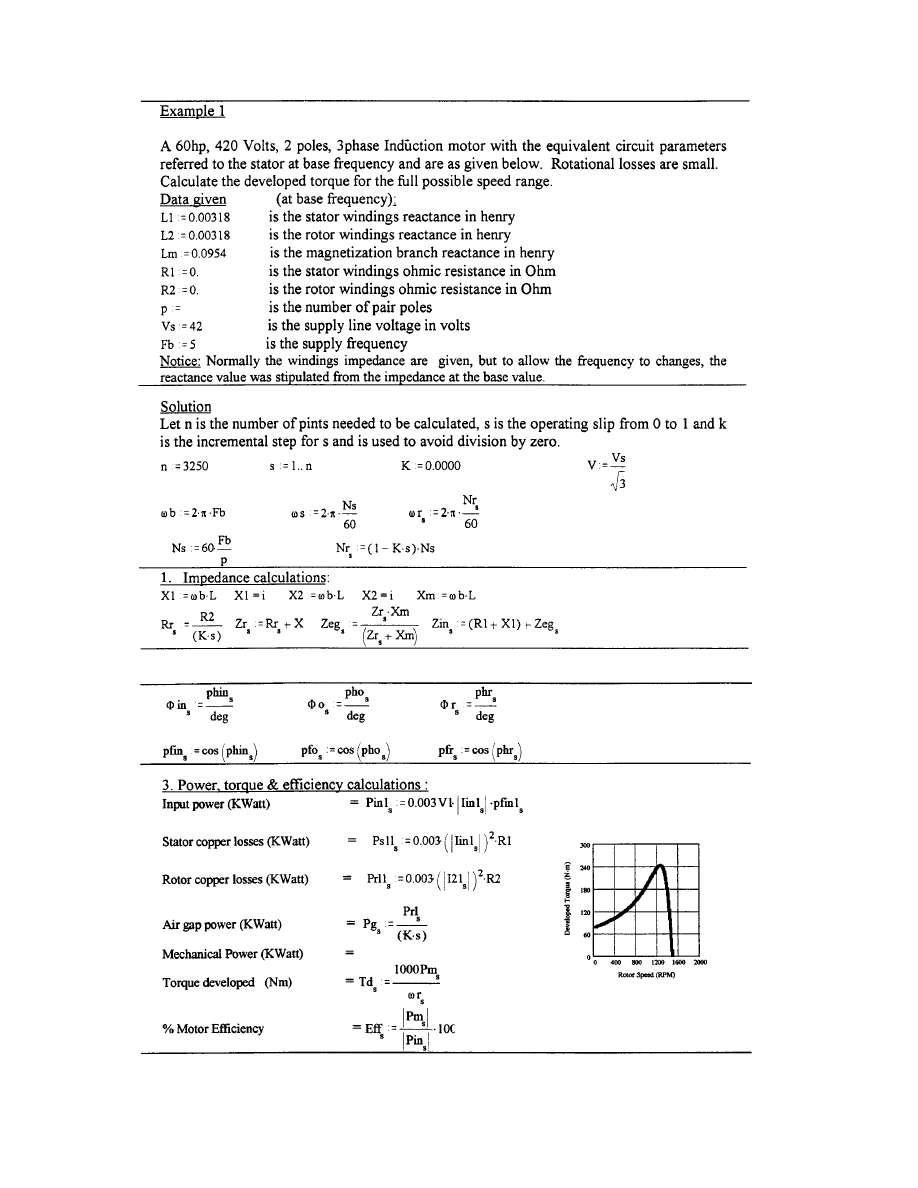
In many textbook examples, the induction motor current can
be estimated with fairly acceptable accuracy using the above
methodology. Example 1 (shown in the Appendix) presents the
standard steps to determine the current, the developed torque
and power using the equivalent circuit for squirrel-cage induc-
tion motor.
Fig. 4.
The three-phase induction motor power flow diagram.
B. The Student Interaction with the Software
At the beginning of the electric machine course, the student
receives a hand out showing the key features of the software and
how the MathCad main built-in features work with the course
material. The practicality of using MathCad software instead of
using the handheld calculator for the student is that it will be
possible to input various configurations of variables without any
programming knowledge. The use of the built-in functions of
MathCad in an interactive and easy way to generate the com-
plete motor characteristics over the entire speed range rather
than one operating point will be more informative for the stu-
dent. This is one of the advantages over the numerical examples
normally presented in the textbook. Therefore, the student can
verify all the possible operating points along the motor char-
acteristics. The examples stored for the student in the electronic
handbook database of the course generate complete characteris-
NIGIM AND DELYSER: USING MATHCAD IN UNDERSTANDING
167
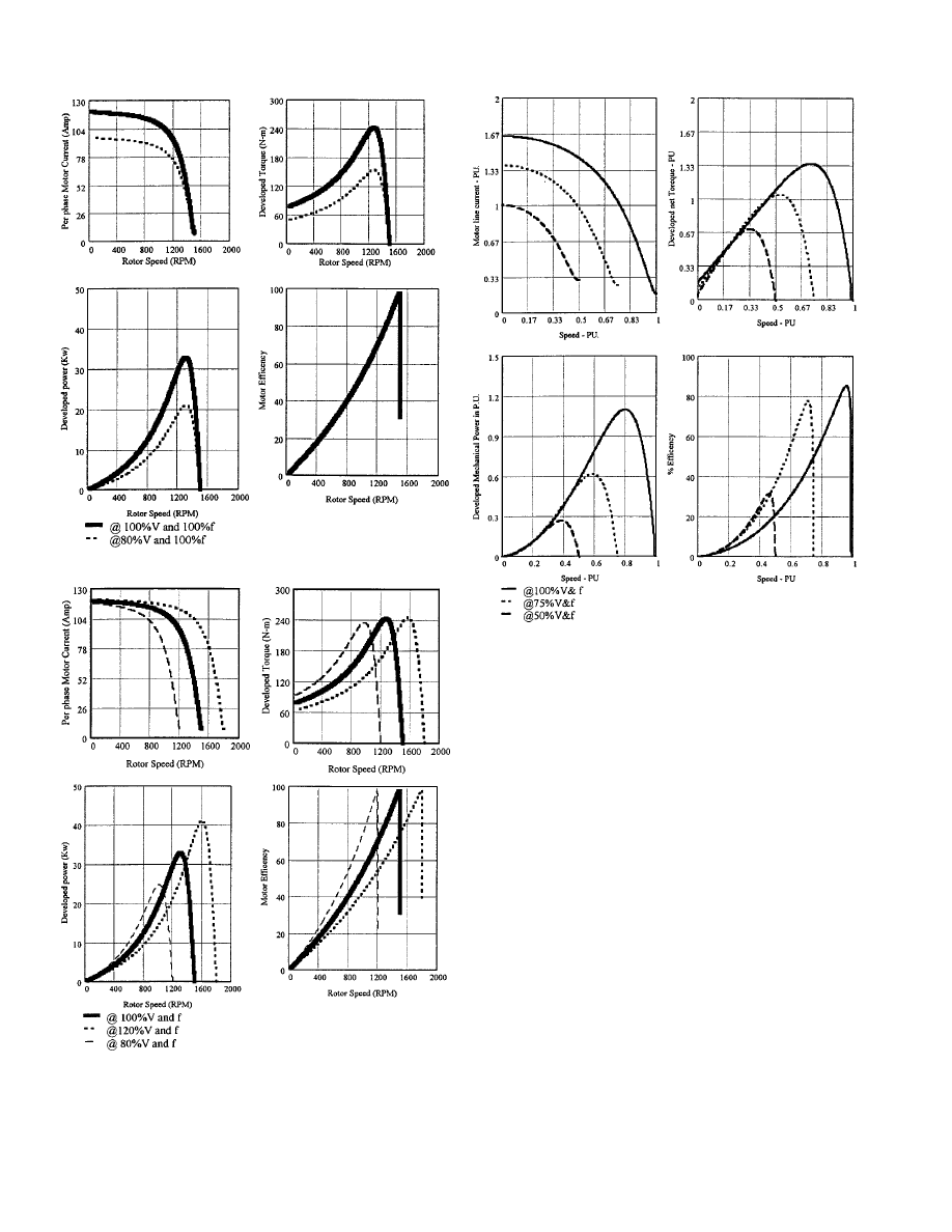
Fig. 5.
Case 1. Studies of the effect of drop in the supply voltage by 20%.
Fig. 6.
Case 2. A look at the effect of maintaining constant magnetic field by
maintaining constant voltage to frequency ratio
v=f 0 k.
tics over the whole speed range allowing the student to examine
the shape and verify different operating points. To produce a
family of curves on one plot only requires the keying in of vari-
able definitions, data and the formulas acceptable to MathCad,
Fig. 7.
Case 3. A look at the effect of maintaining constant magnetic field by
maintaining constant voltage to frequency ratio
v=f 0 k for permanent split
capacitor-start capacitor-run, one-phase induciton motor.
as shown in Example 1. The second step is to verify numerically
the solution by comparison with the textbook result. The numer-
ical values of the calculated variables can be checked using the
MathCad built-in calculator. It is possible to generate a number
of plots representing different operating conditions such as the
variations of voltage and frequency by using “cut and paste” of
the main keyed-in variables and data.
The copied section is pasted on to an empty area in the docu-
ment as many times as required and each time a new subscript
for the variables have to be labeled.
For the tutor, the example should be laid out in a way to be
as close as possible to the text presented in the textbook so as
to assist the student in following the solution procedures. Later
on, the students will be capable of creating their own routines
needed to represent the operating characteristics of the motor
numerically and graphically in a short time without the need of
any programming tool. Furthermore, the software can be used
for verifying laboratory experiments after entering the labora-
tory motor data and the operating conditions using data import
facilities incorporated in MathCad. The recorded test results for
the laboratory machines could be compared for further verifica-
tion between theory and practice.
III. S
IMULATION
C
ASES
To investigate the motor characteristics under varying con-
ditions the following cases were presented and included in the
168
IEEE TRANSACTIONS ON EDUCATION, VOL. 44, NO. 2, MAY 2001
electronic handbook as examples for the student to search in
and alter the input conditions to examine the resulting effect
(some parts of the examples cannot be modified “using the
lock area facility”). Only the graphical format is presented
here as the variables and equations are based on Example 1
data.

NIGIM AND DELYSER: USING MATHCAD IN UNDERSTANDING
169
The three cases of this section (Cases 1 and 2 regarding the
three-phase motor, and Case 3 for the single-phase induction
motor). The three phase motor input current, developed torque,
developed mechanical power and the efficiency for variable
input conditions for the motor used in Example 1 are listed. The
data and input conditions presented by the equivalent circuit
(for the three-phase motor) were varied to investigate the motor
characteristics under different possible control modes:
Case 1, where the supply voltage is reduced by 20%. The
Supply frequency is kept unchanged. The mode is known as
the variable voltage constant frequency operation. The voltage
is reduced either by resistance or autotransformer connected
in series with the supply voltage. Recently phase controlled
thyristors configurations have been used to vary the supply
voltage instead of the autotransformer in many applications.
In this method of speed control, the developed torque per
ampere of input motor current is reduced as the stator voltage is
reduced. Therefore, for constant load torque characteristics, the
motor input current increases as the speed decrease, resulting
in more copper losses (heat) and causes the motor insulation to
deteriorate. This method is well suited for cubic torque-speed
characteristics (such as air blowers and fans).
Case 2, where both voltage and frequency was varied to main-
tain constant magnetic flux. The technique is well adopted in
all ac drives to control the speed and torque of the induction
motors. Since the motor is operated at a constant air gap flux
(the motoring speed range below the synchronous speed), the
torque per ampere is high permitting fast transient response of
the drive system. An another advantage of this type of control
is the capability of starting the motor at the maximum torque. It
is also possible to drive the motor above the synchronous speed
by reducing the voltage and increasing the frequency of what is
known as flux weakening mode (constant power mode).
Case 3, for the one-phase permanent split capacitor induction
motor in which the supply voltage and frequency were main-
tained constant. The motor base supply voltage and frequency
are 110 V at 60 Hz. The control technique is well adopted in
all ac drives to control the speed and torque of the three-phase
induction motor, but has constraints when applied to one-phase
since the motor developed torque decreases below 50% of the
speed due to the inherited one-phase motor characteristics [7].
IV. C
ONCLUSION
MathCad is a good tool to introduce an easy way to evaluate
the steady-state characteristics of the induction motor. The soft-
ware has a high potential for the analysis of system performance
and can be used in simulation techniques effectively. The use
of the built in functions of the software in an interactive and
easy way to generate the complete motor characteristics over
the entire speed range rather than one operating point is more
informative for the student. This is one of the advantages over
the numerical examples normally presented in the textbook. As
computing languages are not essential, the undergraduate engi-
neer can investigate the motor characteristics quickly and easily.
A
PPENDIX
The following shows the result of simulating the motor
characteristics under normal operating conditions for full speed
range. The text was copied from MathCad and inserted in
this document using “cut and paste” through the Windows
clipboard. The example solution procedures were sectionalized
for clarity. The equations were presented in the format that
normally appears in the textbooks.
R
EFERENCES
[1] G. Bengu and W. Swart, “A computer aided, total quality approach to
manufacturing education in engineering,” IEEE Trans. Educ., vol. 39,
Aug. 1996.
[2] K. Foster, “Abstract math made practical,” IEEE Spectrum, Nov. 1993.
[3] G. Kaplan, “Math, visualization and data acquisition,” IEEE Spectrum,
Nov. 1993.
[4] R. Krishnan, A. Bharadwaj, and P. Materu, “Computer aided design of
electrical machine for variable speed applications,” IEEE Trans. Ind.
Electron., vol. 35, no. 4, Nov. 1988.
[5] S. Linke, J. Torgeson, and J. Au, “An interactive computer-graphics pro-
gram to aid instruction in electric machinery,” IEEE Comput. Applicat.
Power, July 1989.
[6] S. E. Zocholl, “Motor Analysis for Protection Engineers,” IEEE
Comput. Applicat. Power, Oct. 1993.
[7] K. A. Nigim, “PC Based Single and Three Phase Induction Motor Drive
Performance Simulation,” in 7th Mediterranean Electrotech. Conf., An-
talya, Turkey, Apr. 1994.
[8] R. Delyzer, “Using MathCad in electromagnetic education,” IEEE
Trans. Educ., vol. 39, pp. 198–209, May 1996.
[9]
MathCad version 6 user manual.
Khalid A. Nigim (M’85) was born in Gaza in 1955. He received the B.Sc. de-
gree in electrical engineering from Zagazig University, Egypt, in 1979. He re-
ceived the Ph.D. degree from the University of Leicester, U.K., in 1983.
He has been an Assistant Professor of Electrical Engineering at Birzeit Uni-
versity, West Bank, since 1983. He was granted several honarary research grants
in the United Kingdom, Germany, and the United States. His research interests
include induction motor speed controllers, solar and wind energy controllers,
FACTS, and microcontrollers for the control of industrial equipment.
Ronald R. DeLyser (S’74–M’75–SM’87) received the B.S. degree from the
University of Florida, Gainesville, in 1974, the M.S. degree from the University
of New Mexico, Albuquerque, in 1978, and the Ph.D. degree from the University
of Colorado, Boulder, in 1991, all in electrical engineering.
As a member of the United States Air Force between 1965 and 1986, held a
teaching position at the United States Air Force Academy, served as a Develop-
ment Engineer at the Air Force Weapons Laboratory at Kirtland AFB in New
Mexico and was the Requirements Officer for the Nellis AFB Ranges in Nevada.
He is currently an Associate Professor of Engineering in the Engineering De-
partment of the University of Denver, where he has been on the faculty since
1986. His research areas include pedagogy, outcomes bases assessment, the
study of periodic gratings used as antennas and in antenna systems, high power
microwave interactions with large complex cavities, anechoic chambers, and
anechoic chamber absorbing materials.
Wyszukiwarka
Podobne podstrony:
2793 artykul 7 id 31748 Nieznany
2892 artykul 1 id 32057 Nieznany
artykul (1) id 69658 Nieznany
Bobath Artykul id 91128 Nieznany
artykul 5 id 69654 Nieznany (2)
finanse artykuly id 172227 Nieznany
m2 artykul 1 id 275067 Nieznany
artykul 4 id 69537 Nieznany
artykul1 id 69679 Nieznany (2)
artykul 3 id 69652 Nieznany (2)
neurologia artykul 2 id 317511 Nieznany
Artykul 5 id 69561 Nieznany (2)
Bunkier Krysia Artykul id 9530 Nieznany (2)
ZKI artykul id 590848 Nieznany
artykul 4 id 69653 Nieznany (2)
2793 artykul 7 id 31748 Nieznany
2892 artykul 1 id 32057 Nieznany
artykul (1) id 69658 Nieznany
artykul profilaktyka cz2 id 695 Nieznany (2)
więcej podobnych podstron