
2002 CAMRY (EWD461U)
3
HOW TO USE THIS MANUAL B
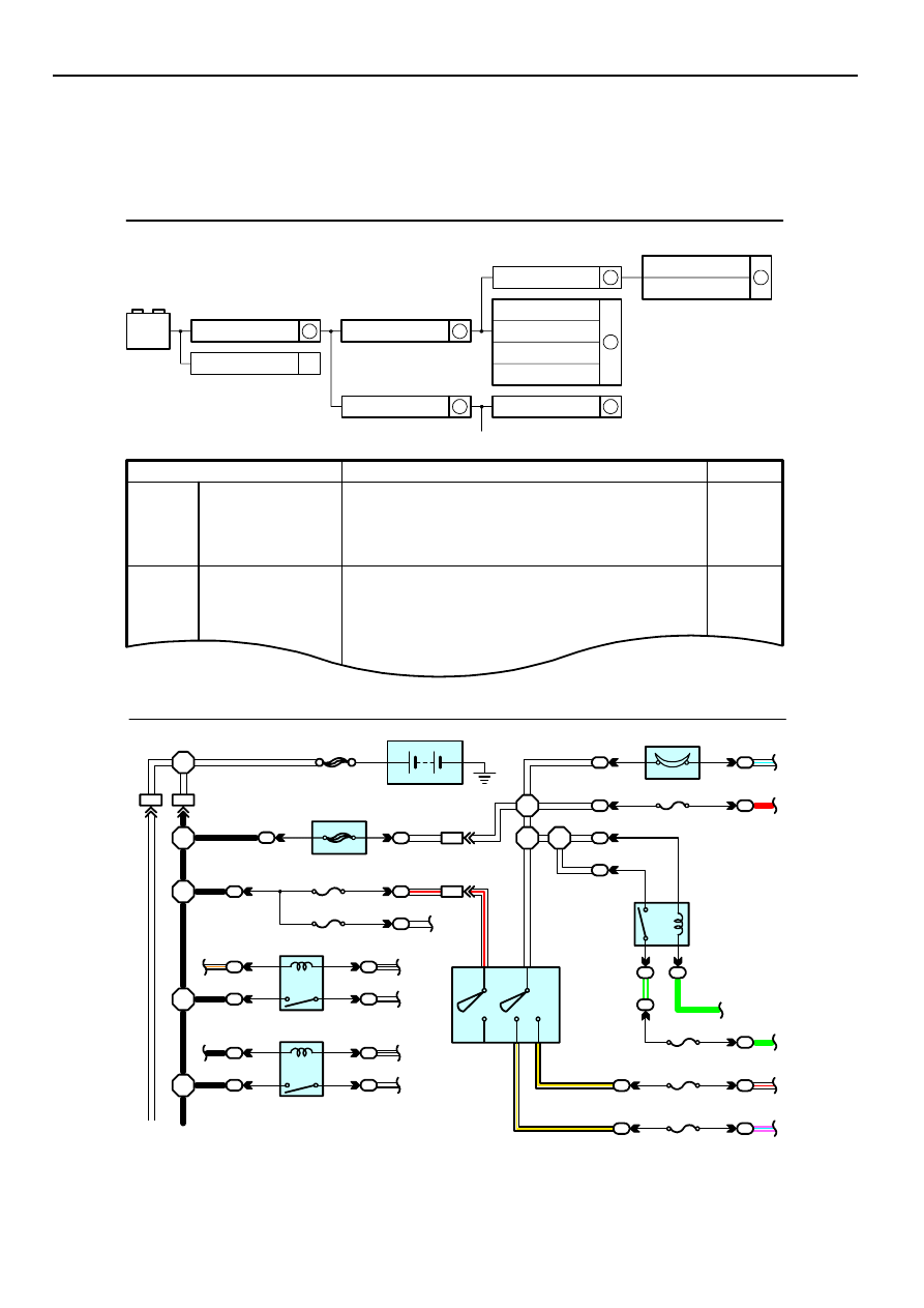
This manual provides information on the electrical circuits installed on vehicles by
dividing them into a circuit for each system.
The actual wiring of each system circuit is shown from the point where the power
source is received from the battery as far as each ground point. (All circuit
diagrams are shown with the switches in the OFF position.)
When troubleshooting any problem, first understand the operation of the circuit
where the problem was detected (see System Circuit section), the power source
supplying power to that circuit (see Power Source section), and the ground points
(see Ground Point section). See the System Outline to understand the circuit
operation.
When the circuit operation is understood, begin troubleshooting of the problem
circuit to isolate the cause. Use Relay Location and Electrical Wiring Routing
sections to find each part, junction block and wiring harness connectors, wiring
harness and wiring harness connectors, splice points, and ground points of each
system circuit. Internal wiring for each junction block is also provided for better
understanding of connection within a junction block.
Wiring related to each system is indicated in each system circuit by arrows
(from__, to__). When overall connections are required, see the Overall Electrical
Wiring Diagram at the end of this manual.
[A]
[B]
[H]
[D]
[F]
[E]
[ I ]
[L]
[M]
[J]
[K]
[G]
[C]
1
2
IB
IB
3
4
4
7
2
1
11
13
4
1
2
6
3
1
2
B18
BL
R L
GR
B18
G R
3
4
Rear Combination Light RH
R 7
Rear Combination Light LH
R 6
High Mounted
Stop Light
H17
Light Failure Sensor
Stop Light SW
ABS ECU
S 6
Combination
Meter
C 7
BV1
1
W B
(Shielded)
BV1
1
I 5
G W
IB
2
IB
1
IE1
14
BO
50
8
L 4
15A
STOP
7.5A
GAUGE
From Power Source System (See Page 66)
Stop Light
GR
WB
WB
WB
WB
GB
YG
YG
R
GR
WR
GW
WB
GW
W/
G
)
(S/D
)
L
L
(
(S/D
)
Stop
Stop
Rear
Lights
2002 CAMRY (EWD461U)
4
B HOW TO USE THIS MANUAL
∗
The system shown here is an EXAMPLE ONLY. It is different to the actual
circuit shown in the SYSTEM CIRCUITS SECTION.
2002 CAMRY (EWD461U)
5
B
[A] : System Title
[B] : Indicates a Relay Block. No shading is used and
only the Relay Block No. is shown to distinguish it
from the J/B
Example: Indicates Relay Block No.1
[C] : ( ) is used to indicate different wiring and
connector, etc. when the vehicle model, engine
type, or specification is different.
[D] : Indicates related system.
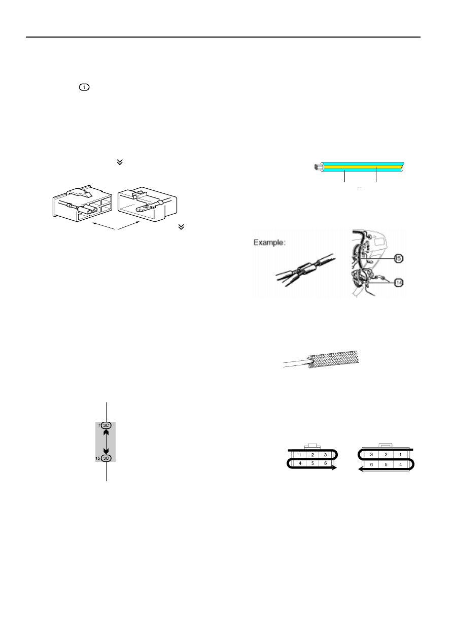
[E] : Indicates the wiring harness and wiring harness
connector. The wiring harness with male terminal is
shown with arrows ( ).
Outside numerals are pin numbers.
Female
Male ( )
The first letter of the code for each wiring harness
and wiring harness connector(s) indicates the
component’s location, e.g, ”E” for the Engine
Compartment, ”I” for the Instrument Panel and
Surrounding area, and ”B” for the Body and
Surrounding area.
When more than one code has the first and second
letters in common, followed by numbers (e.g, IH1,
IH2), this indicates the same type of wiring harness
and wiring harness connector.
[F] : Represents a part (all parts are shown in sky blue).
The code is the same as the code used in parts
position.
[G] : Junction Block (The number in the circle is the J/B
No. and the connector code is shown beside it).
Junction Blocks are shaded to clearly separate
them from other parts.
3C indicates that
it is inside
Junction Block
No.3
Example:
[H] : Indicates the wiring color.
Wire colors are indicated by an alphabetical code.
B
= Black
W = White
BR = Brown
L
= Blue
V
= Violet
SB = Sky Blue
R
= Red
G = Green
LG = Light Green
P
= Pink
Y
= Yellow
GR = Gray
O
= Orange
The first letter indicates the basic wire color and the
second letter indicates the color of the stripe.
Example: L – Y
L
(Blue)
Y
(Yellow)
[I]
: Indicates a wiring Splice Point (Codes are ”E” for the
Engine Room, ”I” for the Instrument Panel, and ”B”
for the Body).
The Location of splice Point I 5 is indicated by the
shaded section.
[J] : Indicates a shielded cable.
[K] : Indicates the pin number of the connector.
The numbering system is different for female and
male connectors.
Example: Numbered in order
from upper left to
lower right
Numbered in order
from upper right to
lower left
Female
Male
[L] : Indicates a ground point.
The first letter of the code for each ground point(s)
indicates the component’s location, e.g, ”E” for the
Engine Compartment, ”I” for the Instrument Panel
and Surrounding area, and ”B” for the Body and
Surrounding area.
[M] : Page No.
[N]
[O]
[P]
[Q]
[R]
[S]
[T]
[U]
2002 CAMRY (EWD461U)
6
B HOW TO USE THIS MANUAL
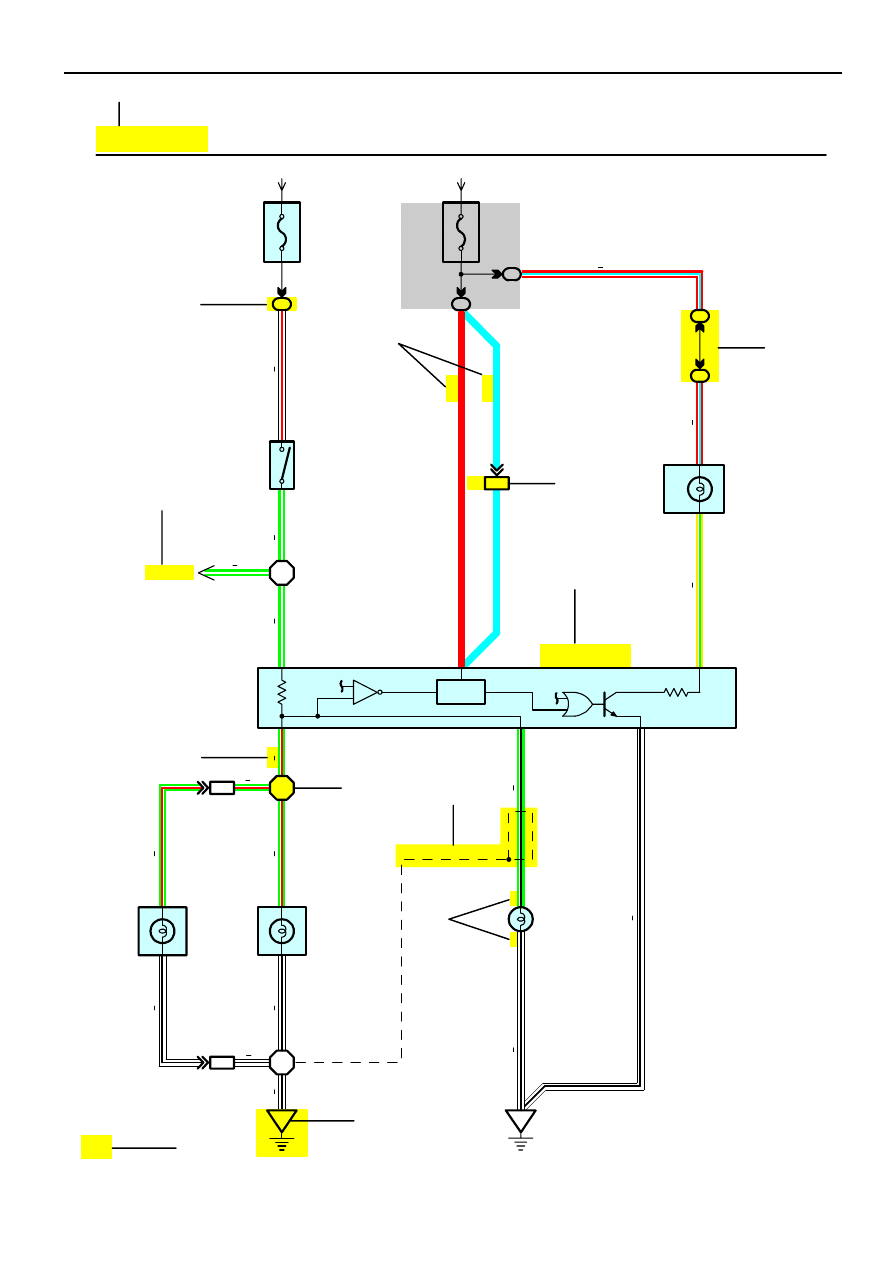
Current is applied at all times through the STOP fuse to TERMINAL 2 of the stop light SW.
When the ignition SW is turned on, current flows from the GAUGE fuse to TERMINAL 8 of the light failure sensor, and also flows
through the rear lights warning light to TERMINAL 4 of the light failure sensor.
Stop Light Disconnection Warning
When the ignition SW is turned on and the brake pedal is pressed (Stop light SW on), if the stop light circuit is open, the current
flowing from TERMINAL 7 of the light failure sensor to TERMINALS 1, 2 changes, so the light failure sensor detects the
disconnection and the warning circuit of the light failure sensor is activated.
As a result, the current flows from TERMINAL 4 of the light failure sensor to TERMINAL 11 to GROUND and turns the rear lights
warning light on. By pressing the brake pedal, the current flowing to TERMINAL 8 of the light failure sensor keeps the warning
circuit on and holds the warning light on until the ignition SW is turned off.
S6 Stop Light SW
2–1 : Closed with the brake pedal depressed
L4 Light Failure Sensor
1, 2, 7–Ground : Approx.
12
volts with the stop light SW on
4, 8–Ground : Approx.
12
volts with the ignition SW at
ON
position
11–Ground : Always continuity
: Parts Location
Code
See Page
Code
See Page
Code
See Page
C7
34
L4
36
R7
37
H17
36
R6
37
S6
35
: Relay Blocks
Code
See Page
Relay Blocks (Relay Block Location)
1
18
R/B No.1 (Instrument Panel Brace LH)
: Junction Block and Wire Harness Connector
Code
See Page
Junction Block and Wire Harness (Connector Location)
IB
20
Instrument Panel Wire and Instrument Panel J/B (Lower Finish Panel)
3C
22
Instrument Panel Wire and J/B No.3 (Instrument Panel Brace LH)
: Connector Joining Wire Harness and Wire Harness
Code
See Page
Joining Wire Harness and Wire Harness (Connector Location)
IE1
42
Floor Wire and Instrument Panel Wire (Left Kick Panel)
BV1
50
Luggage Room Wire and Floor Wire (Luggage Room Left)
: Ground Points
Code
See Page
Ground Points Location
BL
50
Under the Left Center Pillar
BO
50
Back Panel Center
: Splice Points
Code
See Page
Wire Harness with Splice Points
Code
See Page
Wire Harness with Splice Points
I5
44
Cowl Wire
B18
50
Luggage Room Wire
System Outline
Service Hints

2002 CAMRY (EWD461U)
7
B
[N] : Explains the system outline.
[O] : Indicates values or explains the function for reference during troubleshooting.
[P] : Indicates the reference page showing the position on the vehicle of the parts in the system circuit.
Example : Part ”L4” (Light Failure Sensor) is on page 36 of the manual.
∗
The letter in the code is from the first letter of the part, and the number indicates its order in parts
starting with that letter.
Example : L 4
Á
Á
Parts is 4th in order
Light Failure Sensor
[Q] : Indicates the reference page showing the position on the vehicle of Relay Block Connectors in the system circuit.
Example : Connector ”1” is described on page 18 of this manual and is installed on the left side of the instrument
panel.
[R] : Indicates the reference page showing the position on the vehicle of J/B and Wire Harness in the system circuit.
Example : Connector ”3C” connects the Instrument Panel Wire and J/B No.3. It is described on page 22 of this
manual, and is installed on the instrument panel left side.
[S] : Indicates the reference page describing the wiring harness and wiring harness connector (the female wiring
harness is shown first, followed by the male wiring harness).
Example : Connector ”IE1” connects the floor wire (female) and Instrument panel wire (male). It is described on
page 42 of this manual, and is installed on the left side kick panel.
[T] : Indicates the reference page showing the position of the ground points on the vehicle.
Example : Ground point ”BO” is described on page 50 of this manual and is installed on the back panel center.
[U] : Indicates the reference page showing the position of the splice points on the vehicle.
Example : Splice point ”I5” is on the Cowl Wire Harness and is described on page 44 of this manual.
2002 CAMRY (EWD461U)
8
B HOW TO USE THIS MANUAL
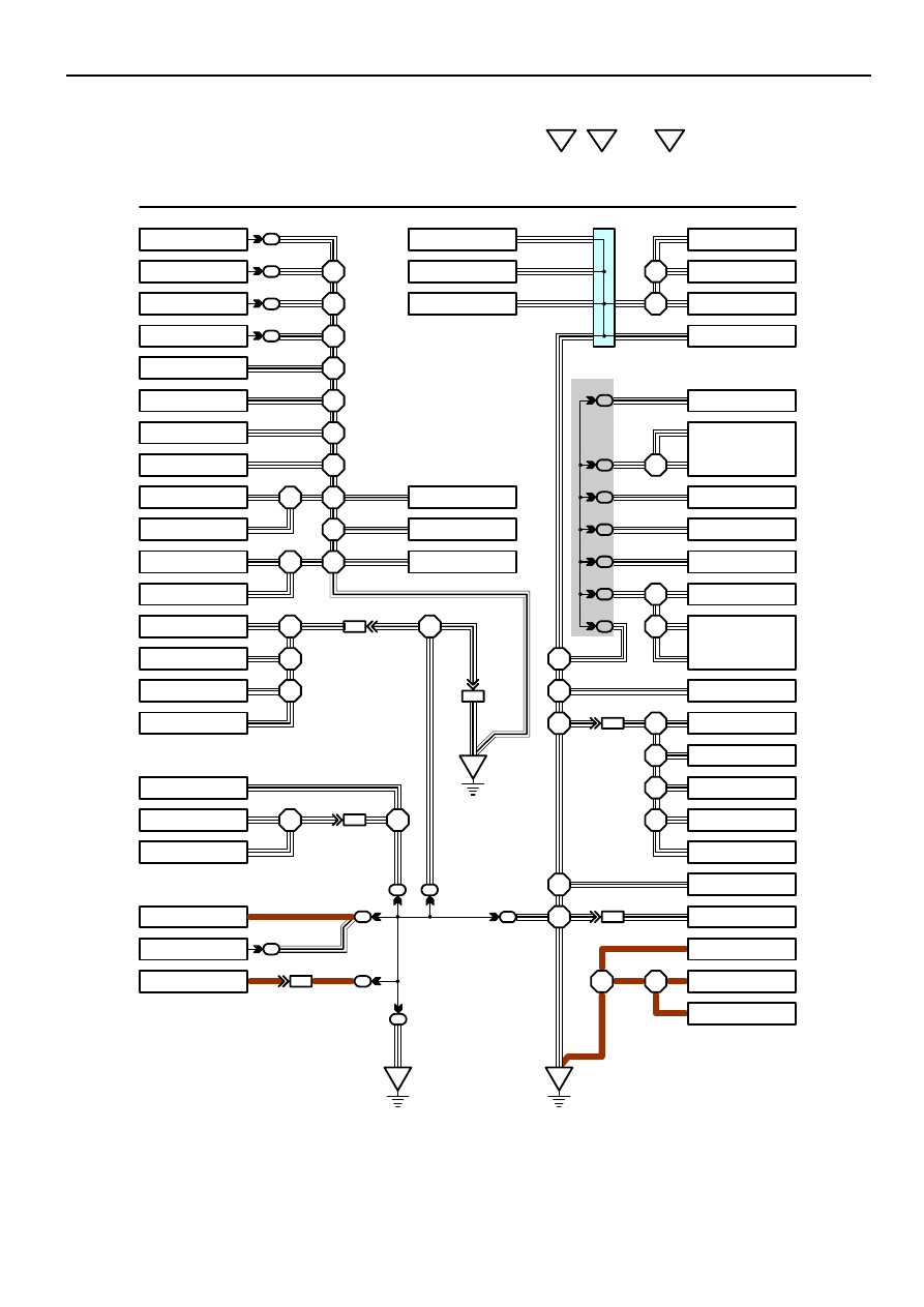
The ground points circuit diagram shows the connections from all major parts to the respective ground points. When
troubleshooting a faulty ground point, checking the system circuits which use a common ground may help you identify
the problem ground quickly. The relationship between ground points (
EA
,
IB
and
IC
shown below) can also be
checked this way.
5
5
5
5
4
4
4
4
4
BA1
5
IB1
8
EA2
ID1
15
IC3
3
IA1
2
E 3
W–B
W–B
W–B
W–B
W–B
W–B
W–B
W–B
W–B
W–B
W–B
W–B
W–B
W–B
W–B
W–B
W–B
W–B
W–B
W–B
W–B
W–B
W–B
W–B
W–B
W–B
W–B
W–B
BR
W–B
BR
BR
W–B
W–B
W–B
W–B
W–B
W–B
W–B
W–B
W–B
W–B
W–B
W–B
W–B
W–B
BR
W–B
BR
BR
BR
W–B (4A–GZE)
W–B
W–B
I 2
I 2
B 5
I 5
I 5
I 5
B 5
B 5
B 5
I 5
I 5
I 3
I 3
E 3
E 3
E 3
E 2
E 4
E 5
E 4
E 5
E 6
E 4
E 4
B 4
EA
I 4
B 4
B 4
I 4
I 8
IB
IC
4
4
3E
5
3E
6
3G
13
3F
3
3D
1
3B
7
W–B
W–B
W–B
W–B
W–B
W–B
W–B
W–B
W–B
W–B
W–B
W–B
W–B
W–B
W–B
I 6
I 6
I 2
3C
7
10
A
A
A
A
A
A
Junction
Connector
J 1
W–B
W–B
W–B
W
–B
BR
W–B
W–B
W–B
W–B
W–B
W–B
I GROUND POINT
FAN MAIN Relay
FAN MAIN Relay
A/C Relay No.2
A/C Relay No.3
Radiator Fan Motor
Headlight Cleaner Relay
Headlight LH
Headlight RH
Front Fog Light LH
Brake Fluid Level SW
Front Fog Light RH
Front Turn Signal Light RH
Front Clearance Light RH
Front Turn Signal Light LH
Front Clearance Light LH
Door Lock Control SW
Door Courtesy SW RH
Door Lock Motor RH
Door Lock Control Relay
Blower Resistor
Idle–Up SW
A/C Amplifier
Radio and Player
HEATER Relay
Auto Antenna Motor
A/C Control Assembly
Blower Motor
Blower SW
Parking Brake SW
Combination Meter
Combination SW
Cruise Control ECU
Remote Control Mirror SW
Turn Signal Flasher
Defogger SW
Unlock Warning SW
Power Window Master SW
Power Window Control
Relay
Door Courtesy SW LH
Door Lock Control SW
Door Lock Motor LH
Fuel Control SW
Woofer Speaker Amplifier
Combination Meter
Combination Meter
Fuel Sender
Cigarette Lighter
O/D Main SW
Clock
Combination SW
∗
The system shown here is an EXAMPLE ONLY. It is different to the actual circuit shown in the SYSTEM CIRCUITS SECTION.
2002 CAMRY (EWD461U)
9
B
The ”Current Flow Chart” section, describes which parts each power source (fuses, fusible links, and circuit breakers)
transmits current to. In the Power Source circuit diagram, the conditions when battery power is supplied to each system
are explained. Since all System Circuit diagrams start from the power source, the power source system must be fully
understood.
ACC
S 2
6
6
5
2
2
2
Battery
30A AM2
Starter
Short Pin
100A ALT
Fusible Link Block
60A ABS
10A ECU–B
7.5A DOME
15A EFI
10A HAZARD
20A RADIO NO.1
10A HORN
20A
10A
Fuse
Page
214
230
112
122
194
187
180
166
210
ABS
Cigarette Lighter
Combination Meter
Key Reminder and Seat Belt Warning
Light Auto Turn Off
Theft Deterrent and Door Lock Control
ABS and Traction Control
Cruise Control
Electronically Controlled Transmission
Multiplex Communication System
STOP
System
DOME
Headlight
Interior Light
3 EA2 1 EA1
E 6
E 7
E 7
2
2
2
2
2
2
2
2
INJECTION Relay
STARTER Relay
B
B
B
B–O
1
1
2
2
3
4
3
4
W–B
W–B
B–W
B–W
E 7
E 7
B
B
W
1.25B FL MAIN
50A MAIN
7.5A AM2
15A HAZ–RADIO
2
2
2
2
2
W
W
EB1
EB1
7
6
W–R
I 2
I 2
I 2
W
W
W
W
W
1
1
1
1
40A DOOR LOCK CB
7.5A DOME
1
W–L
R
1
1
2
4
3
1
1
1
1
1
1
1
G
G
W–R
15A TAIL
20A DEFOG
B–Y
8
4
3
2
Ignition SW
I 8
B–Y
1
1
P–L
Battery
15A RAD CIG
2
TAIL
Relay
Power Source
J POWER SOURCE (Current Flow Chart)
Engine Room R/B (See Page 20)
2
W
W
B
B
B
B
B
W–R
WW
W
G–W
AM2
AM1
IG2
IG1
W
W
The chart below shows the route by which current flows from the battery to each electrical source
(Fusible Link, Circuit Breaker, Fuse, etc.) and other parts.
∗
The system shown here is an EXAMPLE ONLY. It is different to the actual circuit shown in the SYSTEM CIRCUITS SECTION.
Black
[D]
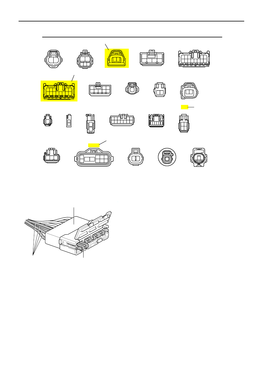
K CONNECTOR LIST
J4
K1
K2
L1
L2
L3
L4
M1
M2
M3
M4
N1
N2
O1
O2
Dark Gray
Gray
Dark Gray
Black
Gray
Gray
A B B
A A B C C C
D D
D D
A
A
A
A
A
A
A A
1
1 2
1 2
1
1
2
1
2
1 2 3
6 7 8 9 101112
4 5
7
1
2
3 4 5 6 8
4
3
2
1
1
2 3
2
3 4
8
9 10
5
6
1
7
1
2
1
1
[A]
[C]
[B]
J3
1
2
1
2
6 7 8
1 2
A
A
A
A
A
A
A B B
A A B C C C
D D
D D
I14
I15
I16
J1
J2
Dark Gray
Gray
Black
2002 CAMRY (EWD461U)
10
B HOW TO USE THIS MANUAL
[A] : Indicates connector to be connected to a part. (The numeral indicates the pin No.)
[B] : Junction Connector
Indicates a connector which is connected to a short terminal.
Junction Connector
Short Terminal
Same Color
Junction connector in this manual include a short terminal which is
connected to a number of wire harnesses. Always perform
inspection with the short terminal installed. (When installing the
wire harnesses, the harnesses can be connected to any position
within the short terminal grouping. Accordingly, in other vehicles,
the same position in the short terminal may be connected to a wire
harness from a different part.)
Wire harness sharing the same short terminal grouping have the
same color.
[C] : Parts Code
The first letter of the code is taken from the first letter of part, and the numbers indicates its order in parts which
start with the same letter.
[D] : Connector Color
Connectors not indicated are milky white in color.
A 1
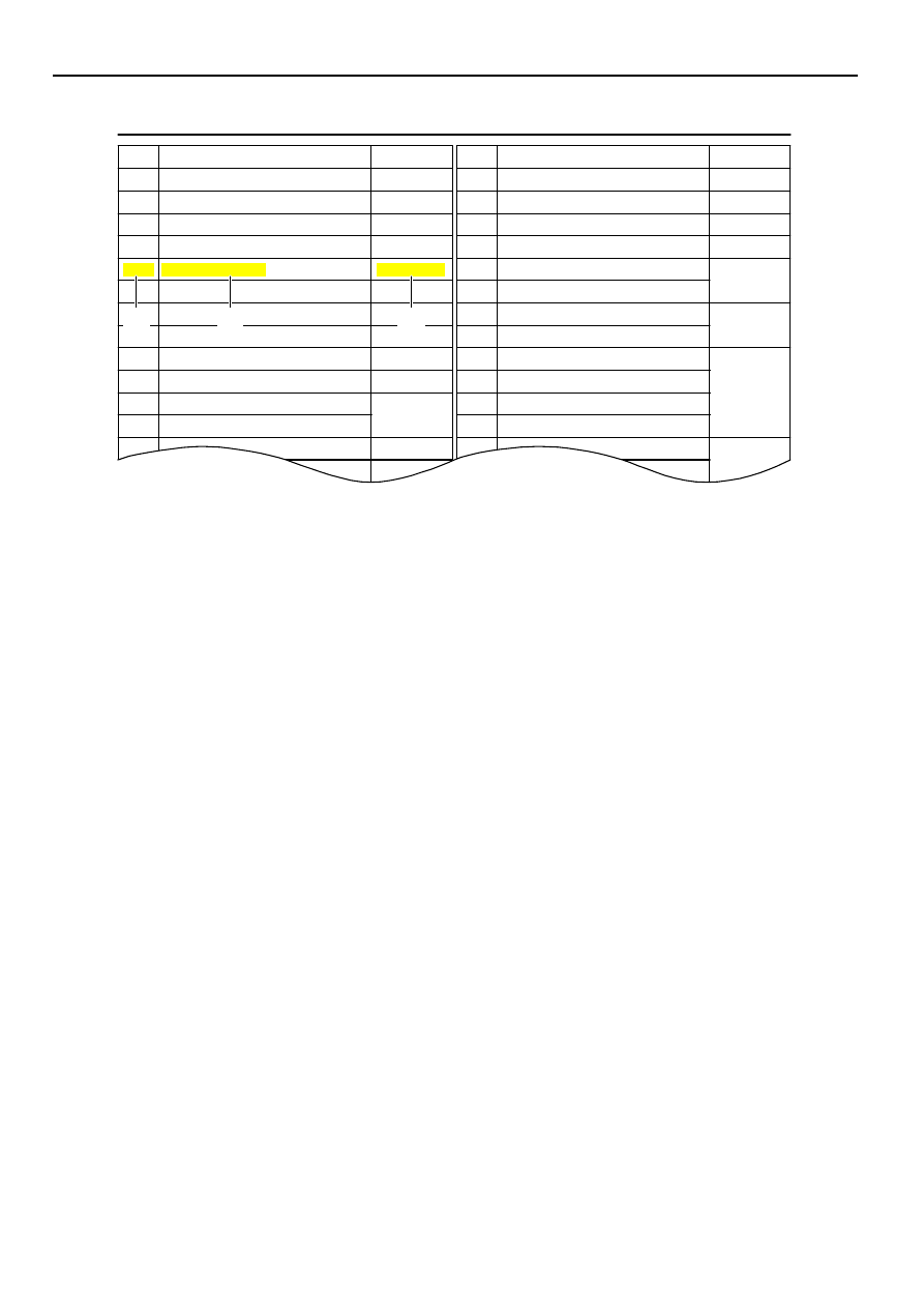
L PART NUMBER OF CONNECTORS
A/C Ambient Temp. Sensor
Code
90980–11070
Part Number
D 4
Diode (Courtesy)
Code
90980–11608
A 2
A/C Condenser Fan Motor
90980–11237
D 5
Diode (Interior Light)
90980–10962
A 3
A/C Condenser Fan Relay
90980–10940
D 6
Diode (Moon Roof)
90980–11608
A 4
A/C Condenser Fan Resistor
90980–10928
90980–11271
D 7
Door Lock Control Relay
90980–10848
A 5
A/C Magnetic Clutch
90980–11413
D 8
Door Lock Control SW LH
90980–11148
A 6
A/T Oil Temp. Sensor
90980–11151
D 9
Door Lock Control SW RH
A 7
ABS Actuator
90980–11009
Door Courtesy SW LH
90980–11097
A 8
ABS Actuator
90980–10941
Door Courtesy SW RH
A 9
ABS Speed Sensor Front LH
90980–11002
Door Courtesy SW Front LH
ABS Speed Sensor Front RH
90980–11856
Door Courtesy SW Front RH
90980–11156
Airbag Sensor Front LH
Door Courtesy SW Rear LH
Airbag Sensor Front RH
Door Courtesy SW Rear RH
A10
A11
A12
A13
Airbag Squib
90980–11194
Door Key Lock and Unlock SW LH
90980–11170
90980–11070
D10
D11
D12
D13
D14
D15
D16
D17
Door Key Lock and Unlock SW RH
Part Number
Part Name
Part Name
[A]
[B]
[C]
2002 CAMRY (EWD461U)
11
B
[A] : Part Code
[B] : Part Name
[C] : Part Number
Toyota Part Number are indicated.
Not all of the above part numbers of the connector are established for the supply. In case of ordering a connector
or terminal with wire, please confirm in advance if there is supply for it using
“
Parts Catalog News” (published by
Parts Engineering Administration Dept.).
Wyszukiwarka
Podobne podstrony:
EWD How to Use this Manual
How to Use the Overall EWD
How to Use Linked In
how to use toyota lexus smart key programmer
How to Use the Electrical Wiring Diagram
How to Use RGB LEDs Backlight o Nieznany
How to use blush, Moda-Uroda
how to use fvdi fwdownloader fiat
How to use software of Ethernet packet?pture to?pture WAN port packets
how to use the flash tool for Xperia
How To launch a liferaft manually
! Martial Arts How To Use Tai Chi As A Fighting Art (Erle Montaigue)
How to Use a Graphic LCD id 206 Nieznany
how to use fgtech with bdm function
How to use Award WinFlash utility
więcej podobnych podstron