W.Kucewicz
Podstawy Elektroniki
1
Ćwiczenie 1
Ćwiczenie 1
Ćwiczenie 1
Ćwiczenie 1
Budowa
Budowa
sterownika do
sterownika do
wyświetlacza
wyświetlacza
7-segmentowego
7-segmentowego
przy użyciu
przy użyciu
bramek
bramek
W.Kucewicz
Podstawy Elektroniki
2
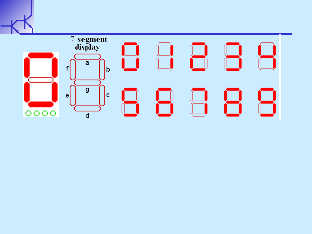
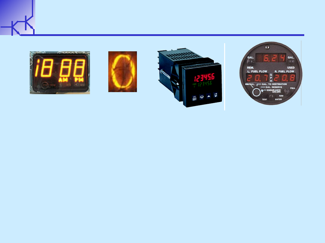
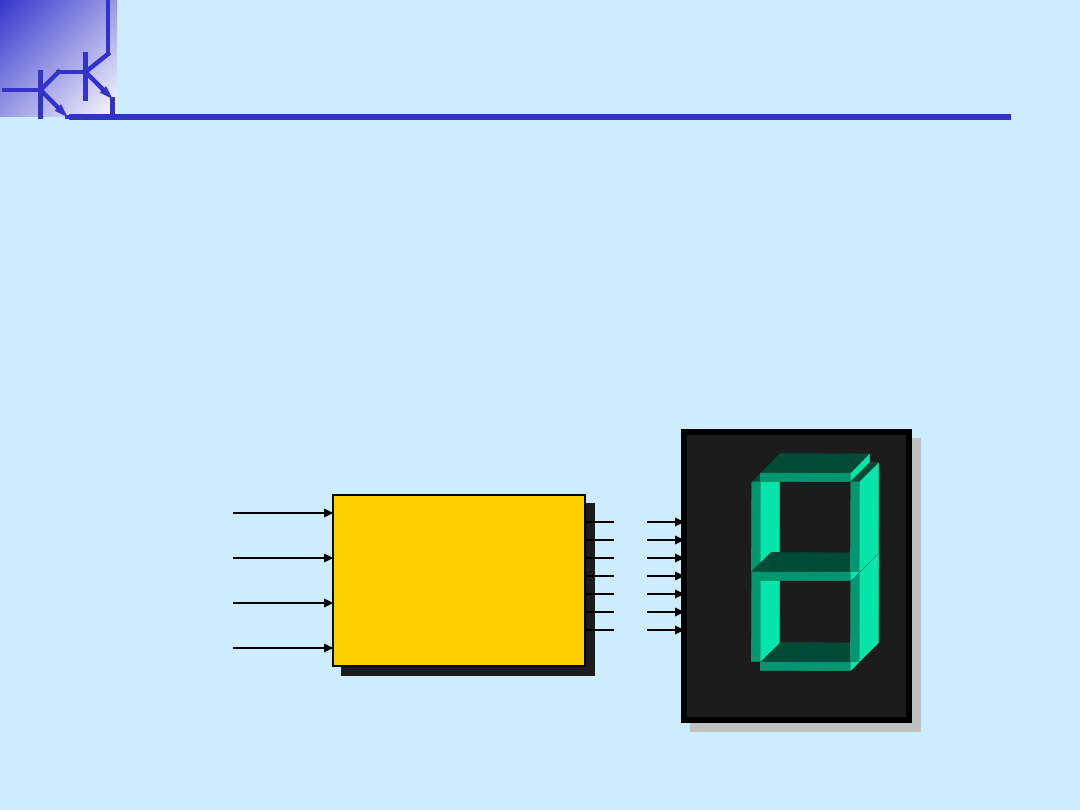
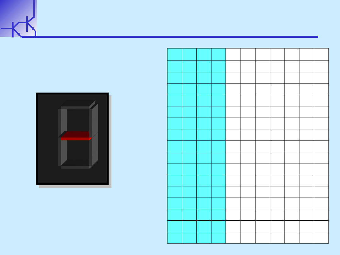
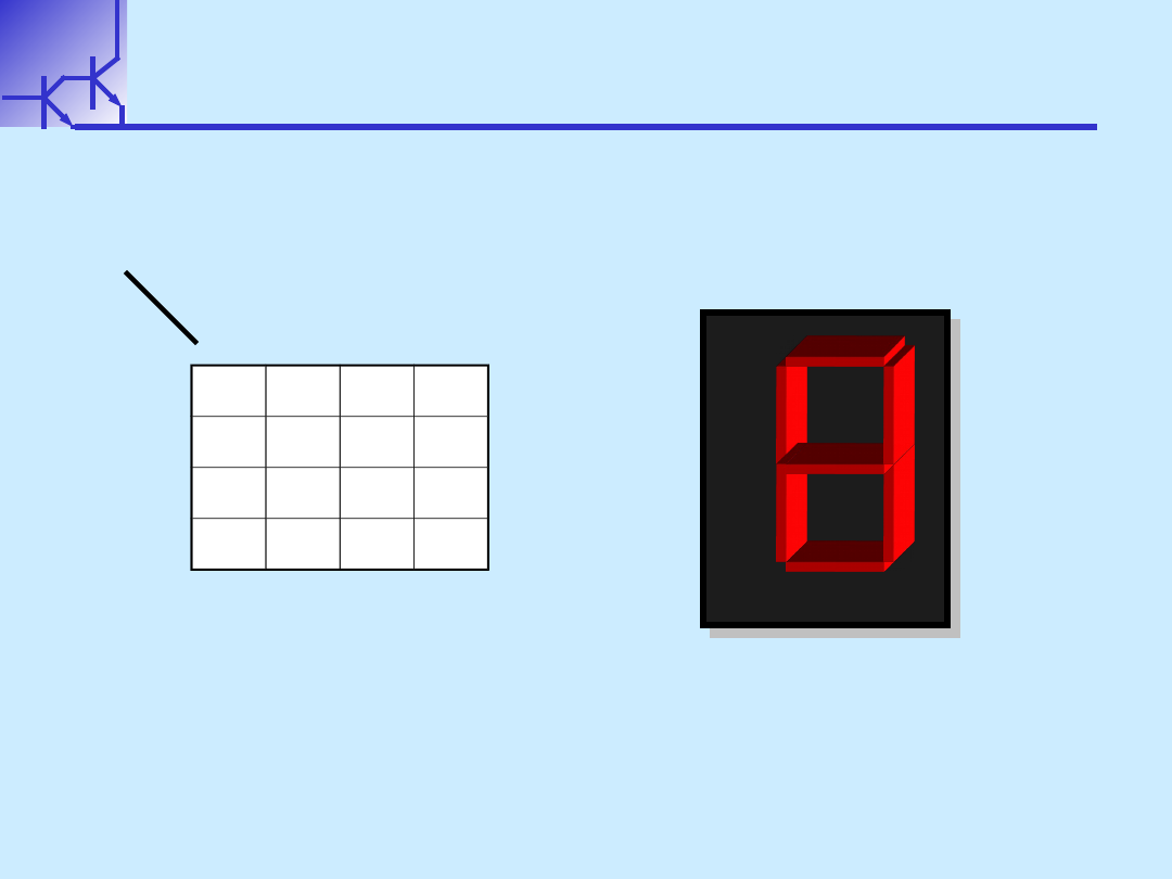
7 Segment Displays
7 Segment Displays
Binary inputs are converted to a decimal number
Binary inputs are converted to a decimal number
display by turning on a set of 7 LEDs
display by turning on a set of 7 LEDs
W.Kucewicz
Podstawy Elektroniki
3
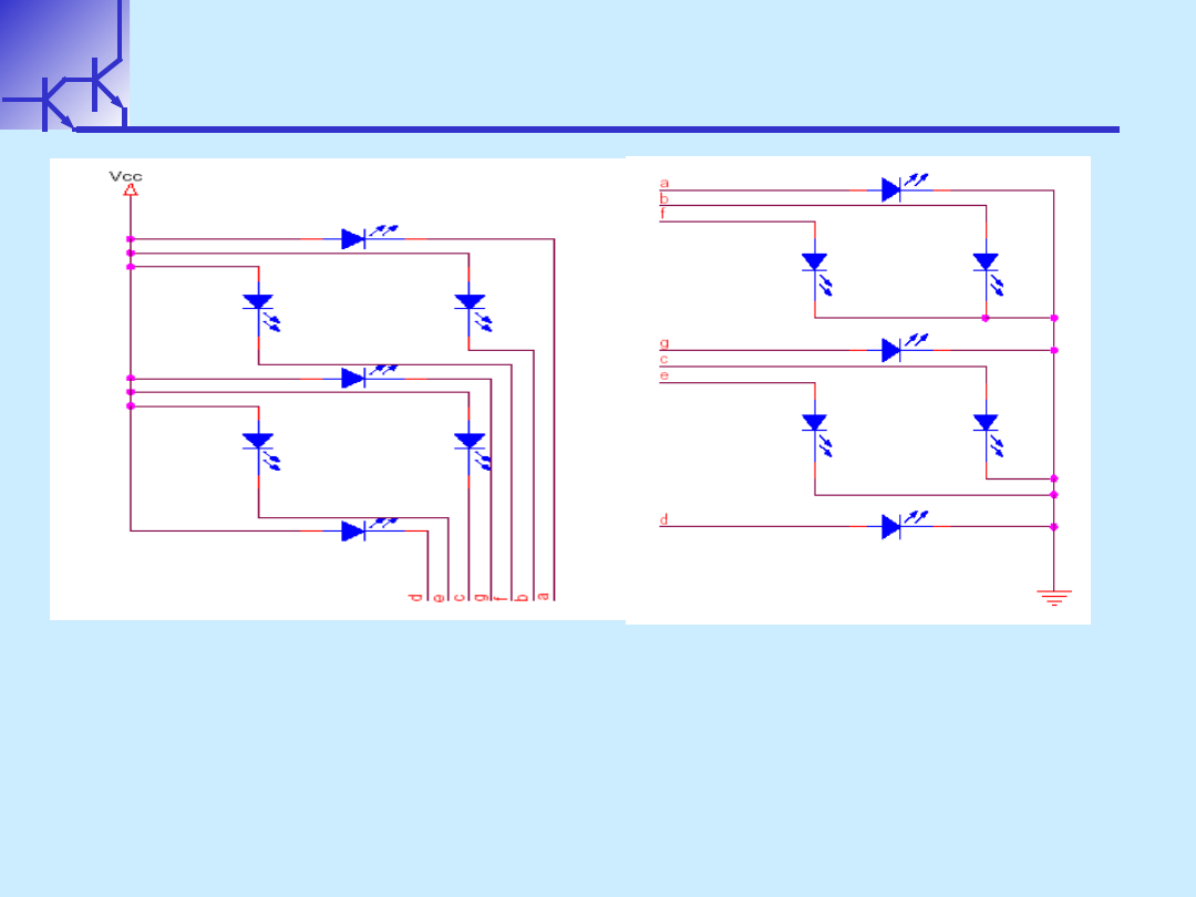
7 Segment Displays
7 Segment Displays
Common cathode at the right and common
Common cathode at the right and common
anode at the left
anode at the left
W.Kucewicz
Podstawy Elektroniki
4
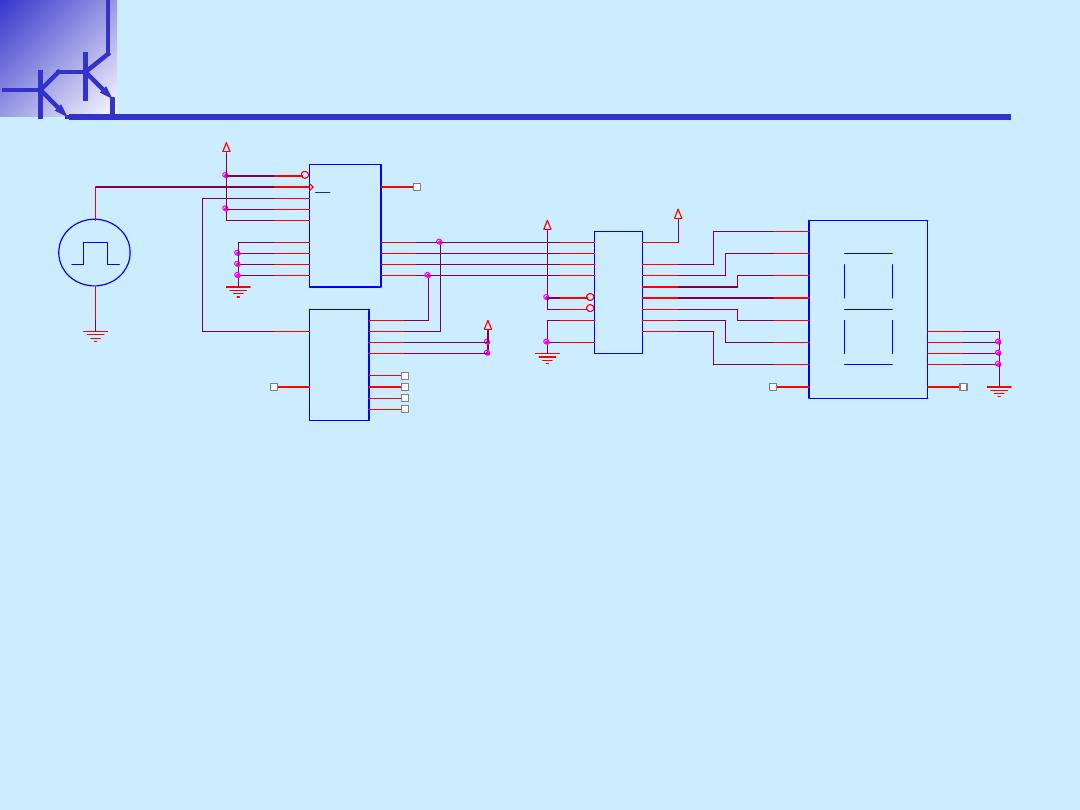
7 Segment Displays
7 Segment Displays
This is the 0-9 counting circuit you will be
This is the 0-9 counting circuit you will be
building in the lab.
building in the lab.
Note that it has to count and then
Note that it has to count and then
convert the binary to show decimal
convert the binary to show decimal
5V
5V
VCC
VCC
14161
3
4
5
6
7
10
9
2
1
14
13
12
11
15
P1
P2
P3
P4
PE
TE
LD
CLK
CL
Q1
Q2
Q3
Q4
CO
14012-chip
2
3
4
5
9
10
11
12
1
13
1A
1B
1C
1D
2A
2B
2C
2D
1Y
2Y
MC14511-b
1
2
3
4
5
6
7
8
9
10
11
12
13
14
15
16
B
C
LT
BI
LE
D
A
GND
e
d
c
b
a
g
f
Vcc
SEVSEG-b
1
2
3
4
5
6
9
10
11
12
13
14
16
a
f
CAT1
e
CAT2
LDP
RDP
d
CAT3
c
g
b
CAT4
1
2
+
-
0-9 circuit
W.Kucewicz
Podstawy Elektroniki
5
Displays Applications
Displays Applications
7 Segments are excellent for displaying
7 Segments are excellent for displaying
simple alphanumeric information –
simple alphanumeric information –
multimeters, clocks, etc.
multimeters, clocks, etc.
More complex displays are needed to
More complex displays are needed to
show images – computer displays,
show images – computer displays,
televisions, etc.
televisions, etc.
W.Kucewicz
Podstawy Elektroniki
6
Sterownik
Sterownik
Sterownik
Sterownik
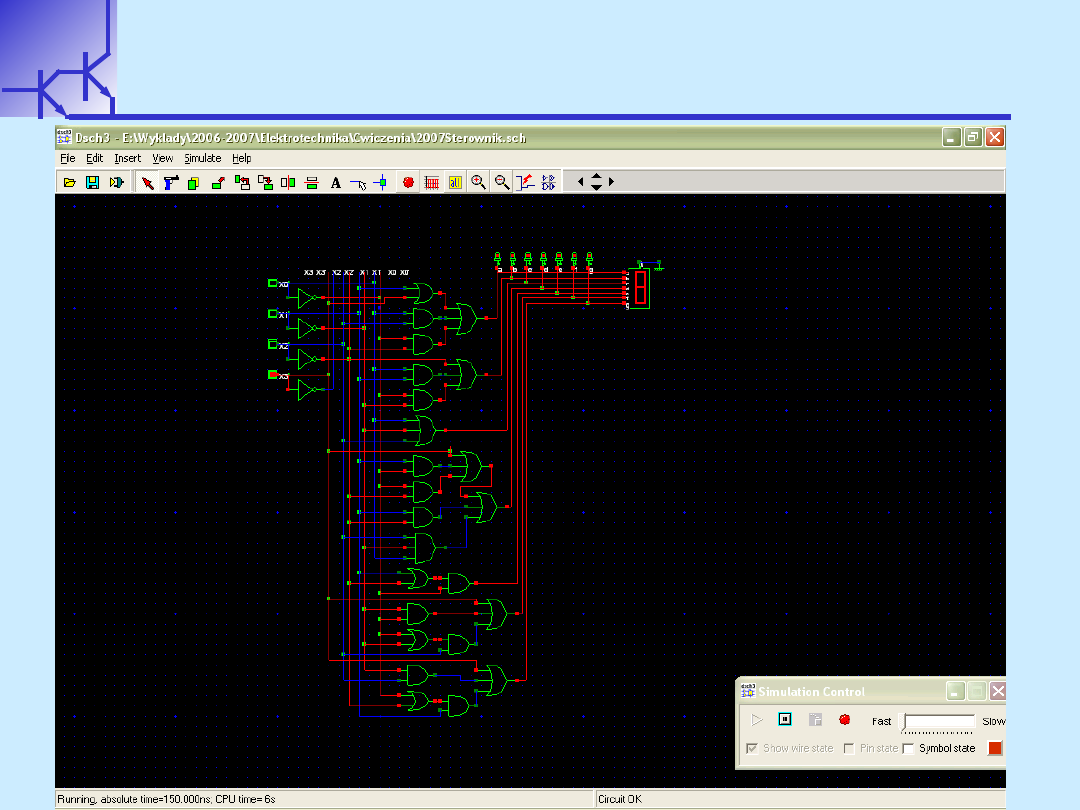
1.
1.
Zdefiniować funkcje logiczne dla sterownika 7-
Zdefiniować funkcje logiczne dla sterownika 7-
segmentowego
segmentowego
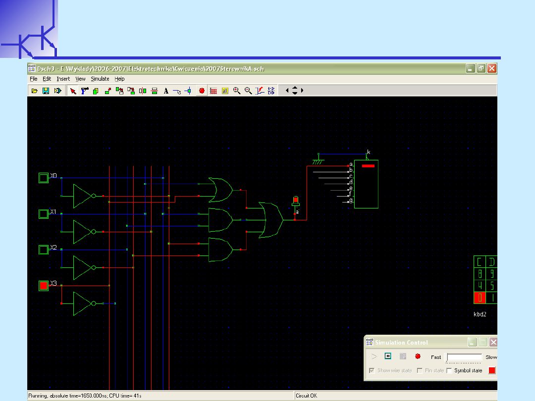
2.
2.
Zbudować model sterownika 7- segmentowego przy
Zbudować model sterownika 7- segmentowego przy
użyciu programu DSCH2
użyciu programu DSCH2
Decoder
Decoder
BCD to 7 segm
BCD to 7 segm
Decoder
Decoder
BCD to 7 segm
BCD to 7 segm
x
x
0
0
x
x
1
1
x
x
2
2
x
x
3
3
c
c
d
d
e
e
f
f
g
g
b
b
a
a
A
A
B
B
C
C
D
D
E
E
F
F
G
G
W.Kucewicz
Podstawy Elektroniki
7
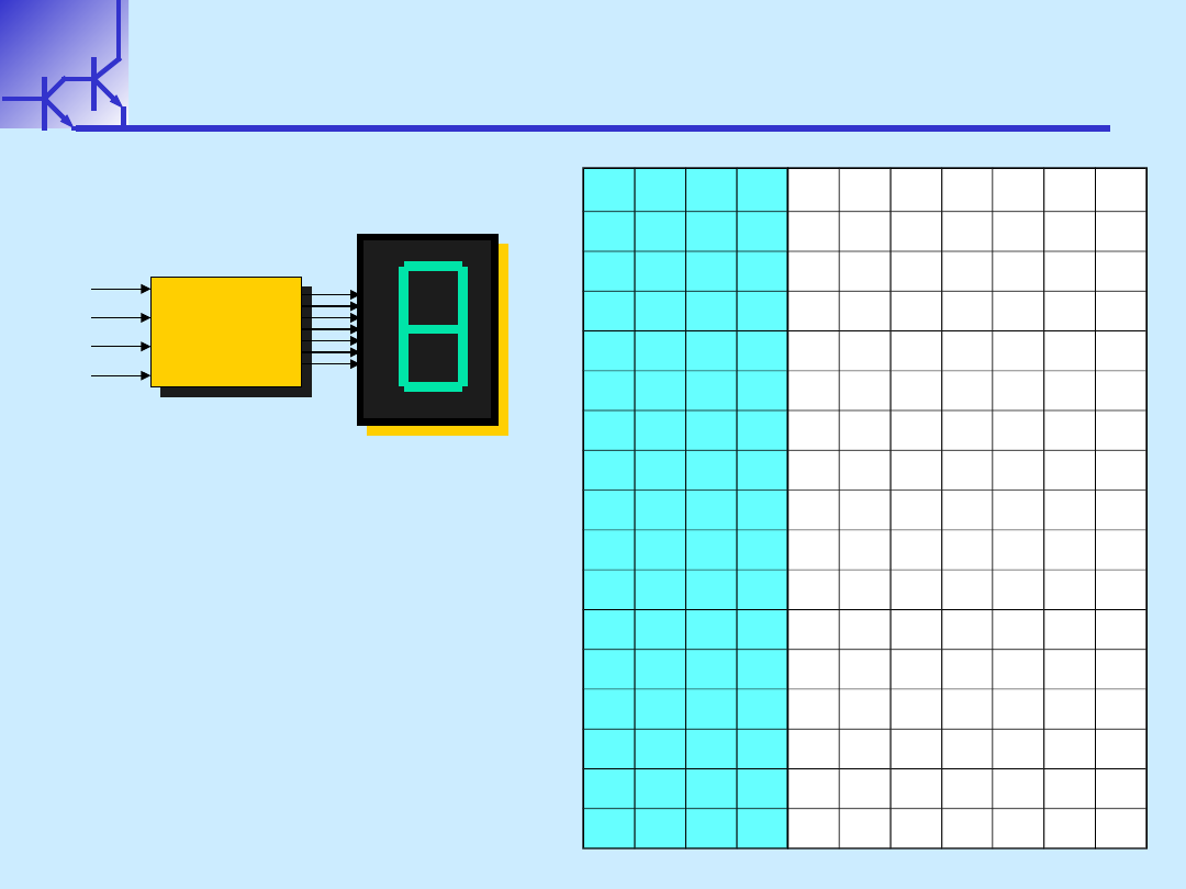
Tablica prawdy
Tablica prawdy
Tablica prawdy
Tablica prawdy
1
1
1
1
1
1
1
1
1
1
1
1
0
0
1
1
1
1
1
1
1
1
1
1
1
1
0
0
Decoder
Decoder
BCD to 7 segm
BCD to 7 segm
Decoder
Decoder
BCD to 7 segm
BCD to 7 segm
x
x
0
0
x
x
1
1
x
x
2
2
x
x
3
3
b
b
c
c
d
d
e
e
f
f
a
a
g
g
1.
1.
Zbuduj tablicę prawdy
Zbuduj tablicę prawdy
x
x
3
3
x
x
2
2
x
x
1
1
x
x
0
0
a
a
b
b
c
c
d
d
e
e
f
f
g
g
0
0
0
0
0
0
0
0
0
0
0
0
0
0
1
1
0
0
0
0
1
1
0
0
0
0
0
0
1
1
1
1
0
0
1
1
0
0
0
0
0
0
1
1
0
0
1
1
0
0
1
1
1
1
0
0
0
0
1
1
1
1
1
1
1
1
0
0
0
0
0
0
1
1
0
0
0
0
1
1
1
1
0
0
1
1
0
0
1
1
0
0
1
1
1
1
1
1
1
1
0
0
0
0
1
1
1
1
0
0
0
0
1
1
1
1
1
1
0
0
1
1
1
1
1
1
1
1
1
1
1
1
1
1
1
1
1
1
1
1
0
0
0
0
1
1
1
1
0
0
0
0
0
0
0
0
1
1
1
1
0
0
1
1
1
1
0
0
1
1
1
1
1
1
1
1
1
1
0
0
0
0
1
1
0
0
1
1
1
1
0
0
0
0
1
1
1
1
1
1
0
0
1
1
1
1
0
0
1
1
1
1
1
1
0
0
1
1
1
1
1
1
1
1
1
1
1
1
1
1
1
1
0
0
0
0
0
0
0
0
1
1
1
1
1
1
1
1
1
1
1
1
1
1
1
1
1
1
1
1
1
1
0
0
1
1
1
1
x
x
x
x
x
x
x
x
x
x
x
x
x
x
x
x
x
x
x
x
x
x
x
x
x
x
x
x
x
x
x
x
x
x
x
x
x
x
x
x
x
x
x
x
x
x
x
x
x
x
x
x
x
x
x
x
x
x
x
x
x
x
x
x
x
x
x
x
x
x
x
x
x
x
x
x
x
x
x
x
x
x
x
x

W.Kucewicz
Podstawy Elektroniki
8
Tablica prawdy
Tablica prawdy
Tablica prawdy
Tablica prawdy
Decoder
Decoder
BCD to 7 segm
BCD to 7 segm
Decoder
Decoder
BCD to 7 segm
BCD to 7 segm
x
x
0
0
x
x
1
1
x
x
2
2
x
x
3
3
b
b
c
c
d
d
e
e
f
f
a
a
g
g
1.
1.
Zbuduj tablicę prawdy
Zbuduj tablicę prawdy
x
x
3
3
x
x
2
2
x
x
1
1
x
x
0
0
a
a
b
b
c
c
d
d
e
e
f
f
g
g
0
0
0
0
0
0
0
0
1
1
1
1
1
1
1
1
1
1
1
1
0
0
0
0
0
0
0
0
1
1
0
0
1
1
1
1
0
0
0
0
0
0
0
0
0
0
0
0
1
1
0
0
1
1
1
1
0
0
1
1
1
1
0
0
1
1
0
0
0
0
1
1
1
1
1
1
1
1
1
1
1
1
0
0
0
0
1
1
0
0
1
1
0
0
0
0
0
0
1
1
1
1
0
0
0
0
1
1
1
1
0
0
1
1
0
0
1
1
1
1
0
0
1
1
1
1
0
0
1
1
1
1
0
0
1
1
1
1
0
0
1
1
0
0
1
1
1
1
1
1
1
1
1
1
0
0
1
1
1
1
1
1
1
1
1
1
1
1
0
0
0
0
0
0
0
0
1
1
0
0
0
0
0
0
1
1
1
1
1
1
1
1
1
1
1
1
1
1
1
1
0
0
0
0
1
1
1
1
1
1
1
1
1
1
0
0
1
1
1
1
1
1
0
0
1
1
0
0
x
x
x
x
x
x
x
x
x
x
x
x
x
x
1
1
0
0
1
1
1
1
x
x
x
x
x
x
x
x
x
x
x
x
x
x
1
1
1
1
0
0
0
0
x
x
x
x
x
x
x
x
x
x
x
x
x
x
1
1
1
1
0
0
0
0
x
x
x
x
x
x
x
x
x
x
x
x
x
x
1
1
1
1
1
1
0
0
x
x
x
x
x
x
x
x
x
x
x
x
x
x
1
1
1
1
1
1
1
1
x
x
x
x
x
x
x
x
x
x
x
x
x
x
W.Kucewicz
Podstawy Elektroniki
9
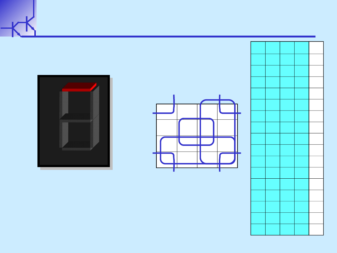
a
a
a
a
1.
1.
Utwórz tablicę Karnaugh dla
Utwórz tablicę Karnaugh dla
sterownika diody
sterownika diody a
a
x
x
3
3
x
x
2
2
x
x
1
1
x
x
0
0
a
a
0
0
0
0
0
0
0
0
0
0
0
0
0
0
1
1
0
0
0
0
1
1
0
0
0
0
0
0
1
1
1
1
0
0
1
1
0
0
0
0
0
0
1
1
0
0
1
1
0
0
1
1
1
1
0
0
0
0
1
1
1
1
1
1
1
1
0
0
0
0
0
0
1
1
0
0
0
0
1
1
1
1
0
0
1
1
0
0
x
x
1
1
0
0
1
1
1
1
x
x
1
1
1
1
0
0
0
0
x
x
1
1
1
1
0
0
0
0
x
x
1
1
1
1
1
1
0
0
x
x
1
1
1
1
1
1
1
1
x
x
c
c
d
d
e
e
f
f
g
g
b
b
a
a
x
x
3
3
x
x
2
2
x
x
1
1
x
x
0
0
00
00
01
01
11
11
10
10
00
00
01
01
11
11
10
10
1
1
0
0
1
1
1
1
0
0
1
1
1
1
1
1
1
1
1
1
X
X
X
X
X
X
X
X
X
X
X
X
a = x
a = x
1
1
+ x
+ x
3
3
+ x
+ x
0
0
x
x
2
2
+
+
x’
x’
0
0
x’
x’
2
2
W.Kucewicz
Podstawy Elektroniki
10
a
a
a
a
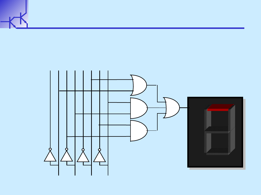
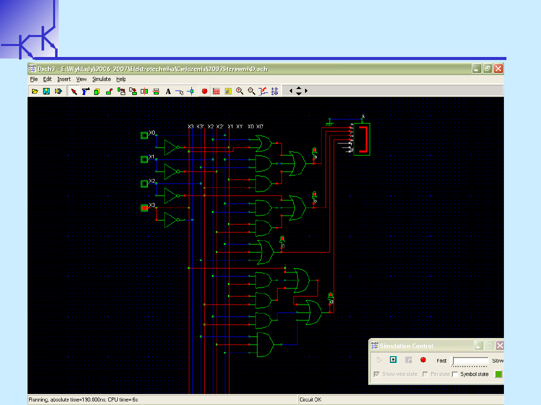
1.
1.
Narysuj schemat układu logicznego dla sterownika
Narysuj schemat układu logicznego dla sterownika
diody
diody a
a
c
c
d
d
e
e
f
f
g
g
b
b
a
a
a = (x
a = (x
1
1
+x
+x
3
3
) + x
) + x
0
0
x
x
2
2
+ x’
+ x’
0
0
x’
x’
2
2
x
x
3
3
x
x
2
2
x
x
1
1
x
x
0
0
W.Kucewicz
Podstawy Elektroniki
11
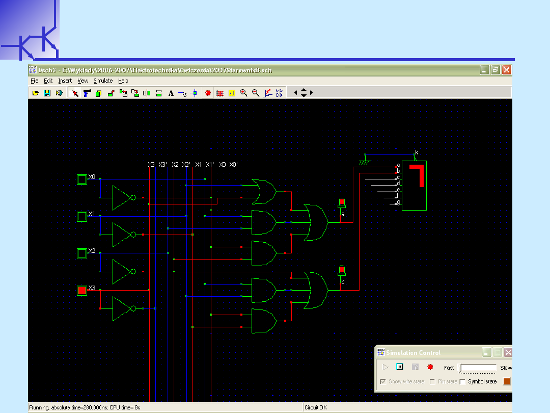
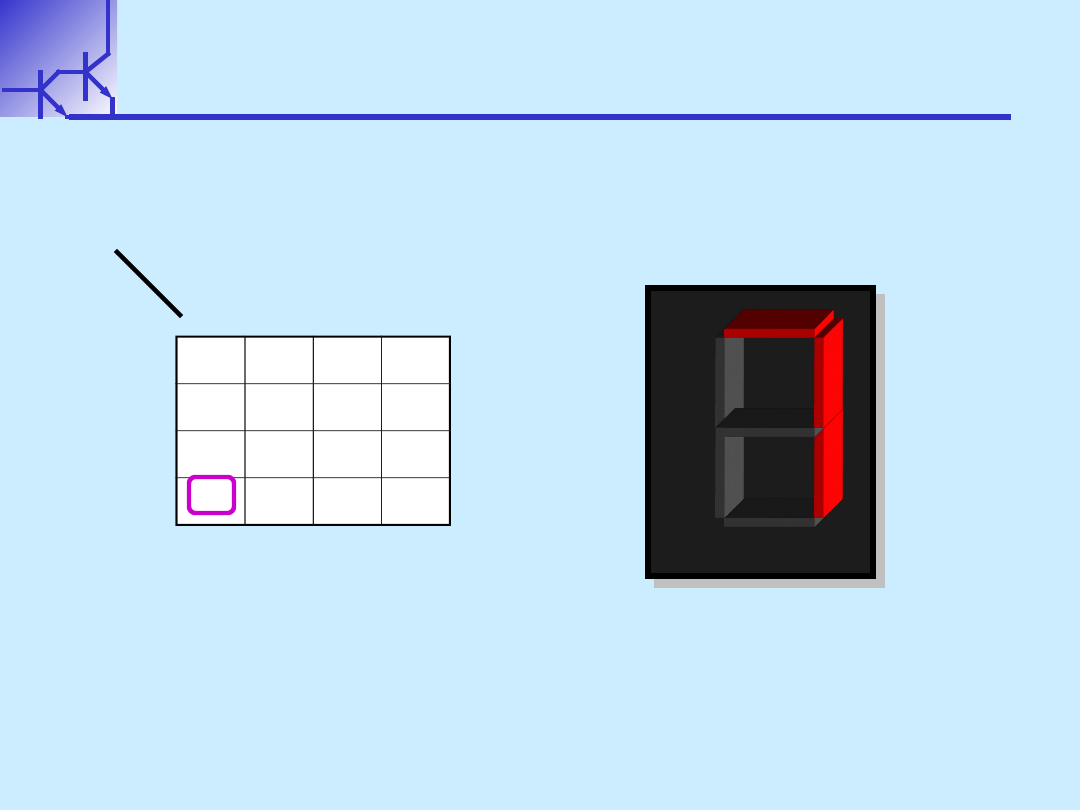
a
a
a
a
W.Kucewicz
Podstawy Elektroniki
12
b
b
b
b
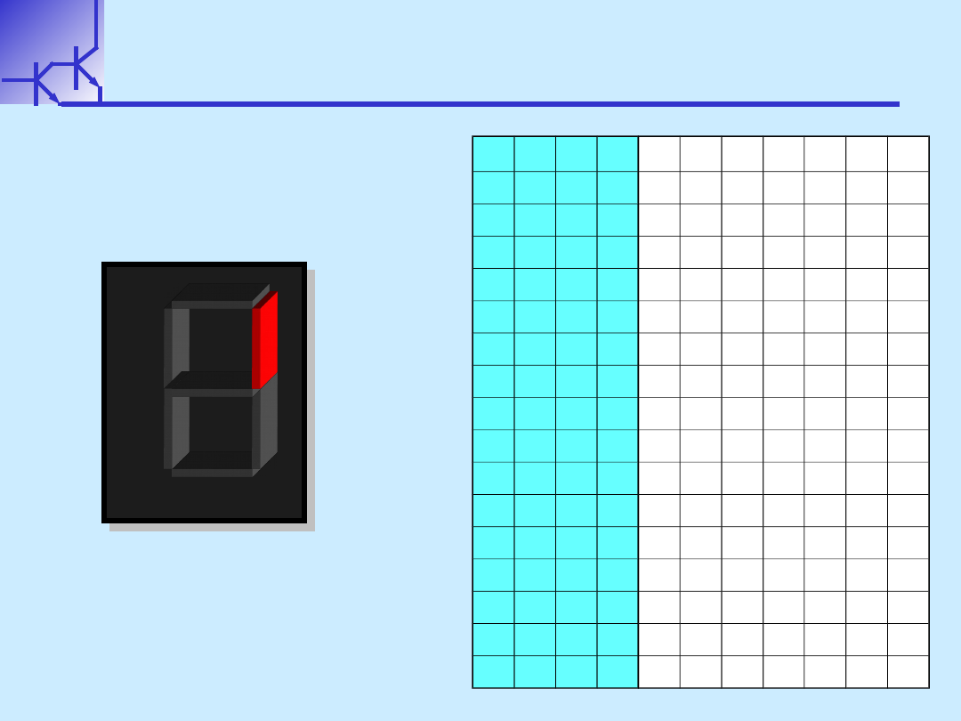
1.
1.
Utwórz tablicę
Utwórz tablicę
Karnaugh dla sterownika
Karnaugh dla sterownika
diody
diody
b
b
x
x
3
3
x
x
2
2
x
x
1
1
x
x
0
0
b
b
0
0
0
0
0
0
0
0
1
1
0
0
0
0
0
0
1
1
1
1
0
0
0
0
1
1
0
0
1
1
0
0
0
0
1
1
1
1
1
1
0
0
1
1
0
0
0
0
1
1
0
0
1
1
0
0
1
1
0
0
0
0
1
1
1
1
0
0
0
0
0
0
1
1
1
1
1
1
1
1
1
1
0
0
0
0
0
0
1
1
1
1
0
0
0
0
1
1
1
1
1
1
0
0
1
1
0
0
x
x
1
1
0
0
1
1
1
1
x
x
1
1
1
1
0
0
0
0
x
x
1
1
1
1
0
0
0
0
x
x
1
1
1
1
1
1
0
0
x
x
1
1
1
1
1
1
1
1
x
x
c
c
d
d
e
e
f
f
g
g
b
b
a
a
W.Kucewicz
Podstawy Elektroniki
13
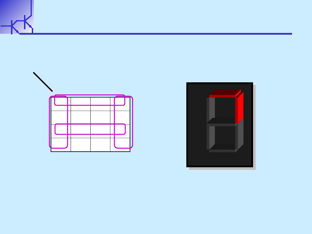
b
b
b
b
x
x
3
3
x
x
2
2
x
x
1
1
x
x
0
0
00
00
01
01
11
11
10
10
00
00
1
1
1
1
x
x
1
1
01
01
1
1
0
0
x
x
1
1
11
11
1
1
1
1
x
x
x
x
10
10
1
1
0
0
x
x
x
x
b = x’
b = x’
2
2
+ x
+ x
1
1
x
x
0
0
+
+
x’
x’
1
1
x’
x’
0
0
2
2
.
.
Wyznacz funkcję logiczną i narysuj schemat układu
Wyznacz funkcję logiczną i narysuj schemat układu
c
c
d
d
e
e
f
f
g
g
b
b
a
a
1.
1.
Utwórz tablicę Karnaugh dla sterownika diody
Utwórz tablicę Karnaugh dla sterownika diody
b
b
W.Kucewicz
Podstawy Elektroniki
14
b
b
b
b

W.Kucewicz
Podstawy Elektroniki
15
c
c
c
c
x
x
3
3
x
x
2
2
x
x
1
1
x
x
0
0
c
c
0
0
0
0
0
0
0
0
1
1
0
0
0
0
0
0
1
1
1
1
0
0
0
0
1
1
0
0
0
0
0
0
0
0
1
1
1
1
1
1
0
0
1
1
0
0
0
0
1
1
0
0
1
1
0
0
1
1
1
1
0
0
1
1
1
1
0
0
1
1
0
0
1
1
1
1
1
1
1
1
1
1
0
0
0
0
0
0
1
1
1
1
0
0
0
0
1
1
1
1
1
1
0
0
1
1
0
0
x
x
1
1
0
0
1
1
1
1
x
x
1
1
1
1
0
0
0
0
x
x
1
1
1
1
0
0
0
0
x
x
1
1
1
1
1
1
0
0
x
x
1
1
1
1
1
1
1
1
x
x
c
c
d
d
e
e
f
f
g
g
b
b
a
a
1.
1.
Utwórz tablicę
Utwórz tablicę
Karnaugh dla sterownika
Karnaugh dla sterownika
diody
diody
c
c
W.Kucewicz
Podstawy Elektroniki
16
c
c
c
c
x
x
3
3
x
x
2
2
x
x
1
1
x
x
0
0
00
00
01
01
11
11
10
10
00
00
1
1
1
1
x
x
1
1
01
01
1
1
1
1
x
x
1
1
11
11
1
1
1
1
x
x
x
x
10
10
0
0
1
1
x
x
x
x
c = x
c = x
0
0
+x
+x
1
1
’+x
’+x
2
2
c
c
d
d
e
e
f
f
g
g
b
b
a
a
1.
1.
Utwórz tablicę Karnaugh dla sterownika diody
Utwórz tablicę Karnaugh dla sterownika diody
c
c
2
2
.
.
Wyznacz funkcję logiczną i narysuj schemat układu
Wyznacz funkcję logiczną i narysuj schemat układu
W.Kucewicz
Podstawy Elektroniki
17
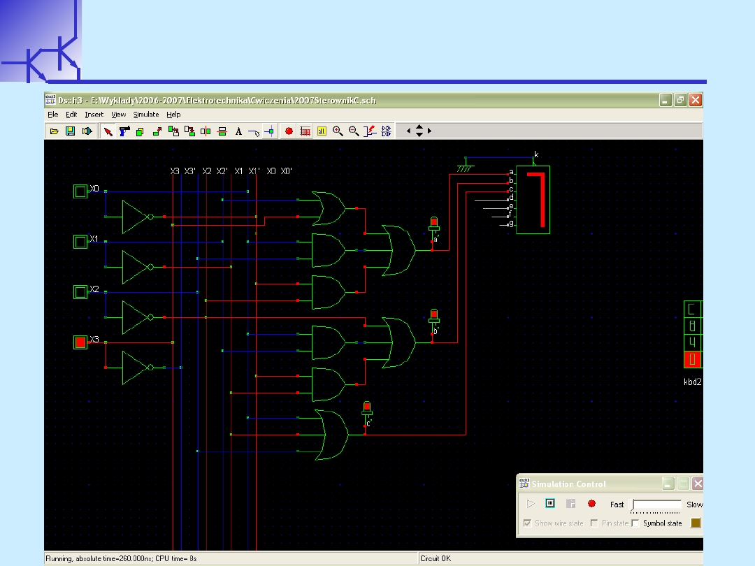
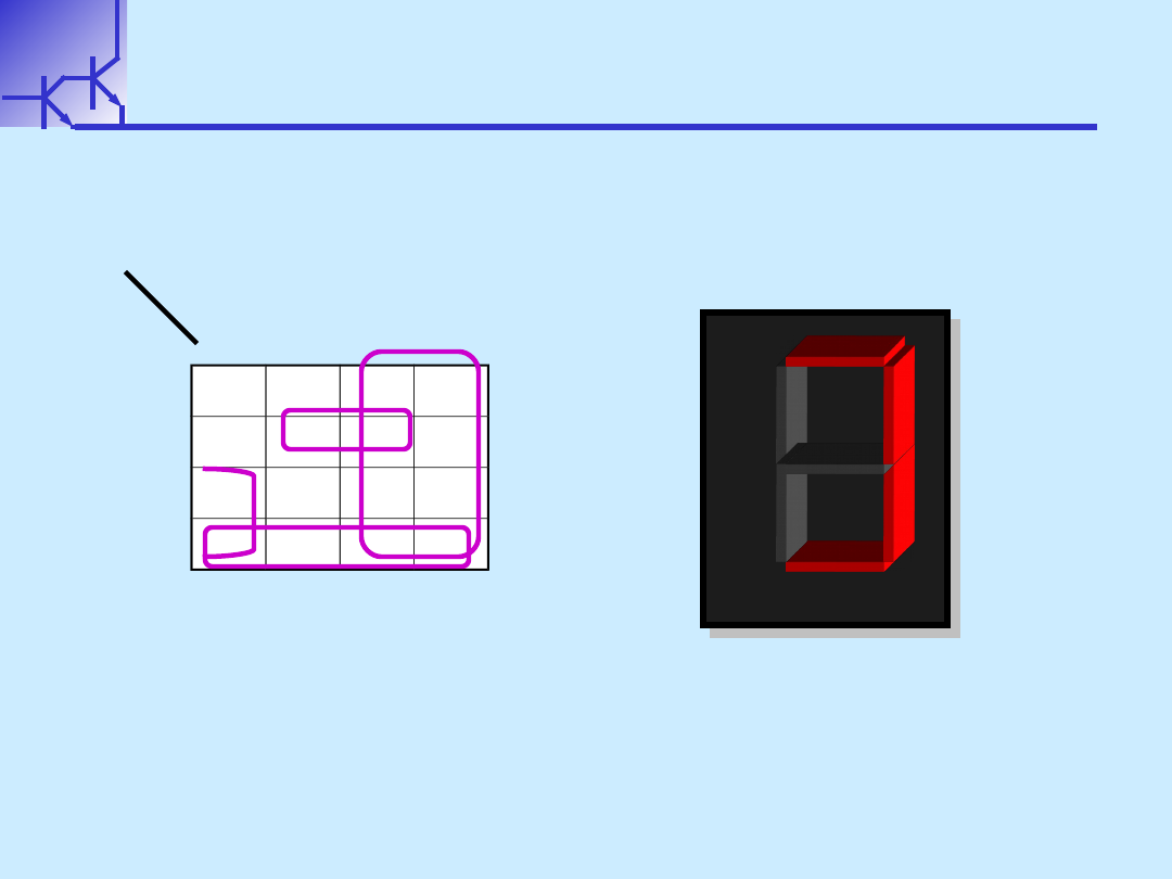
c
c
c
c

W.Kucewicz
Podstawy Elektroniki
18
d
d
d
d
x
x
3
3
x
x
2
2
x
x
1
1
x
x
0
0
d
d
0
0
0
0
0
0
0
0
1
1
0
0
0
0
0
0
1
1
0
0
0
0
0
0
1
1
0
0
1
1
0
0
0
0
1
1
1
1
1
1
0
0
1
1
0
0
0
0
0
0
0
0
1
1
0
0
1
1
1
1
0
0
1
1
1
1
0
0
1
1
0
0
1
1
1
1
1
1
0
0
1
1
0
0
0
0
0
0
1
1
1
1
0
0
0
0
1
1
1
1
1
1
0
0
1
1
0
0
x
x
1
1
0
0
1
1
1
1
x
x
1
1
1
1
0
0
0
0
x
x
1
1
1
1
0
0
0
0
x
x
1
1
1
1
1
1
0
0
x
x
1
1
1
1
1
1
1
1
x
x
c
c
d
d
e
e
f
f
g
g
b
b
a
a
1.
1.
Utwórz tablicę
Utwórz tablicę
Karnaugh dla sterownika
Karnaugh dla sterownika
diody
diody
d
d
W.Kucewicz
Podstawy Elektroniki
19
d
d
d
d
x
x
3
3
x
x
2
2
x
x
1
1
x
x
0
0
00
00
01
01
11
11
10
10
00
00
1
1
0
0
x
x
1
1
01
01
0
0
1
1
x
x
1
1
11
11
1
1
0
0
x
x
x
x
10
10
1
1
1
1
x
x
x
x
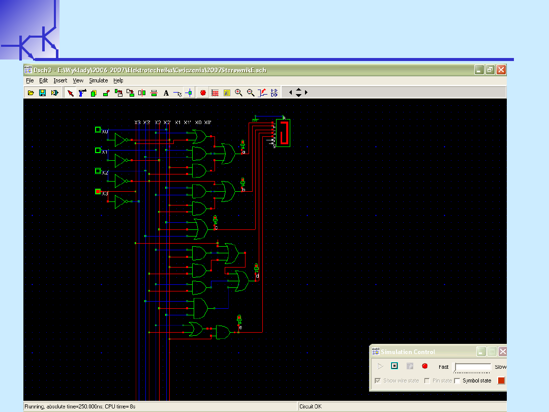
d = x
d = x
3
3
+x
+x
1
1
x’
x’
0
0
+x
+x
1
1
x’
x’
2
2
+x’
+x’
0
0
x’
x’
2
2
+x
+x
0
0
x’
x’
1
1
x
x
2
2
c
c
d
d
e
e
f
f
g
g
b
b
a
a
1.
1.
Utwórz tablicę Karnaugh dla sterownika diody
Utwórz tablicę Karnaugh dla sterownika diody
d
d
2
2
.
.
Wyznacz funkcję logiczną i narysuj schemat układu
Wyznacz funkcję logiczną i narysuj schemat układu
W.Kucewicz
Podstawy Elektroniki
20
d
d
d
d

W.Kucewicz
Podstawy Elektroniki
21
e
e
e
e
x
x
3
3
x
x
2
2
x
x
1
1
x
x
0
0
e
e
0
0
0
0
0
0
0
0
1
1
0
0
0
0
0
0
1
1
0
0
0
0
0
0
1
1
0
0
1
1
0
0
0
0
1
1
1
1
0
0
0
0
1
1
0
0
0
0
0
0
0
0
1
1
0
0
1
1
0
0
0
0
1
1
1
1
0
0
1
1
0
0
1
1
1
1
1
1
0
0
1
1
0
0
0
0
0
0
1
1
1
1
0
0
0
0
1
1
0
0
1
1
0
0
1
1
0
0
x
x
1
1
0
0
1
1
1
1
x
x
1
1
1
1
0
0
0
0
x
x
1
1
1
1
0
0
0
0
x
x
1
1
1
1
1
1
0
0
x
x
1
1
1
1
1
1
1
1
x
x
c
c
d
d
e
e
f
f
g
g
b
b
a
a
1.
1.
Utwórz tablicę
Utwórz tablicę
Karnaugh dla sterownika
Karnaugh dla sterownika
diody
diody
e
e

W.Kucewicz
Podstawy Elektroniki
22
e
e
e
e
x
x
3
3
x
x
2
2
x
x
1
1
x
x
0
0
00
00
01
01
11
11
10
10
00
00
1
1
0
0
x
x
1
1
01
01
0
0
0
0
x
x
0
0
11
11
0
0
0
0
x
x
x
x
10
10
1
1
1
1
x
x
x
x
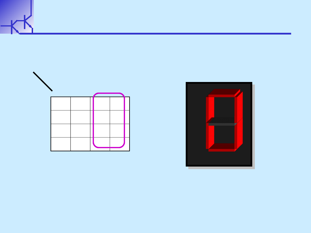
e = x
e = x
1
1
x’
x’
0
0
+
+
x’
x’
0
0
x’
x’
2
2
= x
= x
’
’
0
0
(x
(x
1
1
+ x
+ x
’
’
2
2
)
)
c
c
d
d
e
e
f
f
g
g
b
b
a
a
1.
1.
Utwórz tablicę Karnaugh dla sterownika diody
Utwórz tablicę Karnaugh dla sterownika diody
e
e
2
2
.
.
Wyznacz funkcję logiczną i narysuj schemat układu
Wyznacz funkcję logiczną i narysuj schemat układu
W.Kucewicz
Podstawy Elektroniki
23
e
e
e
e

W.Kucewicz
Podstawy Elektroniki
24
f
f
f
f
x
x
3
3
x
x
2
2
x
x
1
1
x
x
0
0
f
f
0
0
0
0
0
0
0
0
1
1
0
0
0
0
0
0
1
1
0
0
0
0
0
0
1
1
0
0
0
0
0
0
0
0
1
1
1
1
0
0
0
0
1
1
0
0
0
0
1
1
0
0
1
1
0
0
1
1
1
1
0
0
1
1
1
1
0
0
1
1
0
0
1
1
1
1
1
1
0
0
1
1
0
0
0
0
0
0
1
1
1
1
0
0
0
0
1
1
1
1
1
1
0
0
1
1
0
0
x
x
1
1
0
0
1
1
1
1
x
x
1
1
1
1
0
0
0
0
x
x
1
1
1
1
0
0
0
0
x
x
1
1
1
1
1
1
0
0
x
x
1
1
1
1
1
1
1
1
x
x
c
c
d
d
e
e
f
f
g
g
b
b
a
a
1.
1.
Utwórz tablicę
Utwórz tablicę
Karnaugh dla sterownika
Karnaugh dla sterownika
diody
diody
f
f
W.Kucewicz
Podstawy Elektroniki
25
f
f
f
f
x
x
3
3
x
x
2
2
x
x
1
1
x
x
0
0
00
00
01
01
11
11
10
10
00
00
1
1
1
1
x
x
1
1
01
01
0
0
1
1
x
x
1
1
11
11
0
0
0
0
x
x
x
x
10
10
0
0
1
1
x
x
x
x
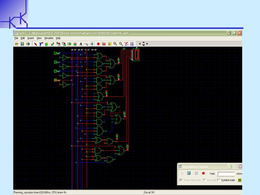
f = x
f = x
3
3
+ x’
+ x’
0
0
x’
x’
1
1
+
+
x’
x’
1
1
x
x
2
2
+
+
x’
x’
0
0
x
x
2
2
=x
=x
3
3
+
+
x’
x’
0
0
x’
x’
1
1
+
+
x
x
2
2
(x’
(x’
1
1
+
+
x’
x’
0
0
)
)
c
c
d
d
e
e
f
f
g
g
b
b
a
a
1.
1.
Utwórz tablicę Karnaugh dla sterownika diody
Utwórz tablicę Karnaugh dla sterownika diody
f
f
2
2
.
.
Wyznacz funkcję logiczną i narysuj schemat układu
Wyznacz funkcję logiczną i narysuj schemat układu
W.Kucewicz
Podstawy Elektroniki
26
f
f
f
f
W.Kucewicz
Podstawy Elektroniki
27
g
g
g
g
x
x
3
3
x
x
2
2
x
x
1
1
x
x
0
0
g
g
0
0
0
0
0
0
0
0
0
0
0
0
0
0
0
0
1
1
0
0
0
0
0
0
1
1
0
0
1
1
0
0
0
0
1
1
1
1
1
1
0
0
1
1
0
0
0
0
1
1
0
0
1
1
0
0
1
1
1
1
0
0
1
1
1
1
0
0
1
1
0
0
1
1
1
1
1
1
0
0
1
1
0
0
0
0
0
0
1
1
1
1
0
0
0
0
1
1
1
1
1
1
0
0
1
1
0
0
x
x
1
1
0
0
1
1
1
1
x
x
1
1
1
1
0
0
0
0
x
x
1
1
1
1
0
0
0
0
x
x
1
1
1
1
1
1
0
0
x
x
1
1
1
1
1
1
1
1
x
x
c
c
d
d
e
e
f
f
g
g
b
b
a
a
1.
1.
Utwórz tablicę
Utwórz tablicę
Karnaugh dla sterownika
Karnaugh dla sterownika
diody
diody
g
g
W.Kucewicz
Podstawy Elektroniki
28
g
g
g
g
x
x
3
3
x
x
2
2
x
x
1
1
x
x
0
0
00
00
01
01
11
11
10
10
00
00
0
0
1
1
x
x
1
1
01
01
0
0
1
1
x
x
1
1
11
11
1
1
0
0
x
x
x
x
10
10
1
1
1
1
x
x
x
x
g = x
g = x
3
3
+ x
+ x
1
1
x’
x’
0
0
+
+
x’
x’
1
1
x
x
2
2
+
+
x
x
1
1
x’
x’
2
2
=
=
x
x
3
3
+ x’
+ x’
1
1
x
x
2
2
+
+
x
x
1
1
(
(
x’
x’
0
0
+
+
x’
x’
2
2
)
)
c
c
d
d
e
e
f
f
g
g
b
b
a
a
1.
1.
Utwórz tablicę Karnaugh dla sterownika diody
Utwórz tablicę Karnaugh dla sterownika diody
g
g
2
2
.
.
Wyznacz funkcję logiczną i narysuj schemat układu
Wyznacz funkcję logiczną i narysuj schemat układu
W.Kucewicz
Podstawy Elektroniki
29
g
g
g
g
Document Outline
- Slide 1
- Slide 2
- Slide 3
- Slide 4
- Slide 5
- Slide 6
- Slide 7
- Slide 8
- Slide 9
- Slide 10
- Slide 11
- Slide 12
- Slide 13
- Slide 14
- Slide 15
- Slide 16
- Slide 17
- Slide 18
- Slide 19
- Slide 20
- Slide 21
- Slide 22
- Slide 23
- Slide 24
- Slide 25
- Slide 26
- Slide 27
- Slide 28
- Slide 29
Wyszukiwarka
Podobne podstrony:
3 ćwiczenia BADANIE asfaltów
Ćwiczenie7
Cwiczenia 2
Ćwiczenia V
metody redukcji odpadów miejskich ćwiczenia
Ćwiczenia1 Elektroforeza
cwiczenia 9 kryzys
Ćwiczenia 1, cz 1
Ćwiczenie 8
9 ćwiczenie 2014
Ćwiczenie 2 Polska w europejskim systemie bezpieczeństwa
11 CWICZENIE 1 SEMESTR LETNIid 12747 ppt
więcej podobnych podstron