
ARMY
TM
5-813-4
AIR FORCE AFM
88-10, VOL. 4
WATER SUPPLY, WATER STORAGE
DEPARTMENTS OF
THE
A R M Y A N D
T H E A I R F O R C E
20 SEPTEMBER 1985

This manual has been prepared
by or for the Government and is
public property and not subject
to copyright.
Reprints or republications of
this manual should include a
credit substantially as follows:
“ J o i n t D e p a r t m e n t s o f t h e
Army and Air Force USA, Tech-
nical Manual TM 5-813-4/AFM
88-10, Volume 4, Water Supply,
Water Storage.
T
ECHNICAL
M
A N U A L
No.
5-813-4
A
IR
F
ORCE
M
ANUAL
No. 88-10, V
OLUME
4
F
IGURE
1-1.
2-.
2-.
HEADQUARTERS
DEPARTMENTS OF THE ARMY
AND
THE AIR FORCE
W
ASHINGTON
, DC, 20 September 1985
WATER SUPPLY, WATER STORAGE
Paragraph
1-1
1-2
2-1
2-2
2-3
DETERMINATION OF CAPACITY REQUIREMENTS
3-1
3-2
3-3
DESIGN AND CONSTRUCTION OF WATER
4-1
4-2
4-3
4-4
4-5
Ôñ}
FIGURES
1-1
1-1
2-1
2-1
2-1
3-1
3-2
3-2
4-1
4-1
4-1
4-1
4-1
A-1
B-1
1-3
2-2
2-3
*This manual supersedes TM 5-813-4/AFM 88-10, Chap. 4, 2 July 1958.
i

1-1. Purpose
This manual provides design criteria for water
storage requirements at military facilities, gives a
typical design analysis for tanks and reservoirs,
and provides guidance on the procedures to be fol-
lowed in selecting sites for such storage works.
The manual covers requirements for treated water
storage in the distribution system, but not the
storage requirements for raw water supplies or
fire deluge systems. This manual is applicable to
all elements of the Army and Air Force planning
and designing water storage facilities at fixed in-
stallations.
1-2. Objectives of Storage
a. Flow requirements. Storage should meet peak
flow requirements, equalize system pressures, and
provide emergency water supply. The water supply
system must provide flows of water sufficient in
quantity to meet all points of demand in the distri-
bution system. To do so, the source must produce
the required quantity and quality, pressure levels
within the distribution system must be high
enough to provide suitable pressure, and water dis-
tribution mains must be large enough to carry
these flows. It is usually inefficient and uneco-
nomical to construct the treatment plant and
pumping stations sufficiently large to meet the
largest anticipated water demands. A water treat-
ment plant is less efficient if flow rates through
the plant are rapidly varied. Water storage facili-
ties are constructed within a distribution network
to meet the peak flow requirements exerted on the
system and to provide emergency storage.
b. Cost. At times it is desirable to know the cost
of constructing water storage for fire protection. In
such cases only the actual fire flow for the fire
period will be used in establishing the proportion-
ate share of the total cost of storage. Cost of that
portion of the storage required for concurrent do-
mestic, industrial, or special demands that cannot
be curtailed during the fire period will not be
charged to fire protection.
c. Meeting peak flow requirements. Water supply
systems must be designed to satisfy maximum an-
ticipated water demands. The peak demands usu-
ally occur on hot, dry, summer days when larger
than normal amounts of water are used for water-
ing lawns and washing vehicles and equipment. In
addition, most industrial processes, especially
those requiring supplies of cooling water, experi-
ence greater evaporation on hot days, thus requir-
ing more water. The water treatment plant can
operate at a relatively uniform rate throughout
the day of maximum demand if enough storage is
available to handle variations in water use. The
necessary storage can be provided in elevated,
ground, or a combination of both types of storage.
d. Distribution system pressures.
(1) System pressure requirements.
(a) Minimum pressures. Water distribution
system, including pumping facilities and storage
tanks or reservoirs, should be designed so that
water pressures of at least 40 lb/in
2
at ground
level will be maintained at all points in the
system, including the highest ground elevations in
the service area. Minimum pressures of 30 lb/in
2
,
under peak domestic flow conditions, can be toler-
ated in small areas as long as all peak flow re-
quirements can be satisfied. During firefighting
flows, water pressures should not fall below 20 lb/
in
2
at the hydrants, in new systems. This require-
ment does not constitute justification for changing
existing storage facilities solely for the purpose of
increasing residual pressures to 20 psi. Refer to
TM 5-813-6/AFM 88-10, Vol. 6 for additional
guidance on minimum residual pressures for fire
flow.
(b) Maximum pressure. Maximum water
pressures in distribution mains and service lines
should not normally exceed 75 lb/in
2
at ground
elevation. Static pressures up to 100 lb/in
2
can be
tolerated in distribution systems in small, low-
lying areas. Higher pressures require pressure re-
ducing valves on feeder mains or individual serv-
ice lines to restrict maximum service pressures to
75 lb/in
2
.
(c) Multiple pressure levels. If an extensive
area has pressures higher than 75 lb/in
2
or lower
than 40 lb/in
2
under a single pressure level config-
uration, it may be appropriate to divide the system
into two or more separate areas, each having dif-
ferent pressure levels. Within each level, pressures
within the distribution system should range from
40 to 75 lb/in
2
at ground elevation.
(2) Pressure distribution with elevated storage.
(a) Elevated storage within the distribution
system permits distribution pumps at the treat-
ment plant to operate at uniform rates.
1-1

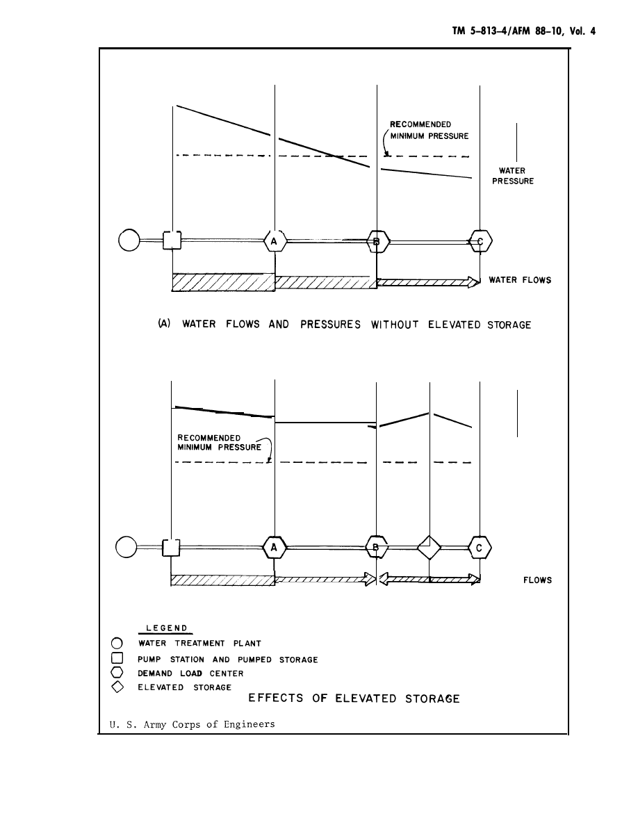
(b)
The usefulness of elevated storage is
shown in figure 1-1. The system illustrated in
figure 1-1 (A) (without
storage at the plant
system demand rates in
tion rate, assuming the
elevated storage) requires
sufficient to provide for
excess of the plant produc-
plant is operated at a uni-
form rate. The pump station forces water into the
service main, through which it is carried to three
load areas: A, B, and C. Since all loads on the
system are met without the use of elevated stor-
age, the pump station must be capable of supply-
ing the peak rates of water use to Areas A, B, and
C, simultaneously, while maintaining the water
pressure to Area C at a sufficient level. The mini-
mum recommended pressure in the distribution
system under peak nonemergency flow conditions
is 40 lb/in
2
. Figure l-l(B) assumes the construc-
tion of an elevated storage tank on the service
main between Areas B and C, with peak loads in
Area C and part of the peak load in Area B being
satisfied from this tank. The elevation of the tank
ensures adequate pressures within the system. The
storage in the tank is replenished when water de-
mands are low and the pump station can fill the
tank while still meeting all flow and pressure re-
quirements in the system. The figure 1-1 (B) ar-
rangement reduces required capacity of the distri-
bution pumps.
(c) Most elevated storage
the distribution system. That is,
tanks “float” on
the elevated tank
is hydraulically connected to the distribution
system, and the volume of water in the tank tends
to maintain system pressures at a uniform level.
When water use is high and pumping facilities
cannot maintain adequate pressures, water is dis-
charged from elevated tanks. Conversely, when
water use is low, the pumps, which operate within
a reasonably uniform head-capacity range, supply
excess water to the system and the elevated stor-
age is refilled.
e. Provision of emergency water supplies.
(1)
Firefighting flows. This demand can occur
at any time, but may well coincide with other
large water demands on the system. Necessary
flows for firefighting purposes are as given in TM
5-813-6/AFM 88-10, Vol. 6, and TM 5-813-7/AFM
88-10, Vol. 7. Storage and distribution facilities
will include capacity for required firefighting flows
at adequate pressures at any point of the installa-
tion.
(2) Other emergencies. Water storage must pro-
vide an emergency supply of water in the event
the water treatment plant, distribution pumps, or
. .
a principal transmission main is out of service.
The amount of emergency storage required de-
pends on the reliability of the system and the
extent of other safeguards incorporated into the
system, i.e., finished water interconnections with a
municipality (for either normal or emergency use).
1 - 2
I
( B ) W A T E R F L O W S A N D P R E S S U R E S W I T H E L E V A T E D
WATER
PRESSURE
WATER
STORAGE
1 - 3

2-1. General
Required storage capacity at military installations
is met by use of elevated or ground storage. Ele-
vated storage, feeds the water distribution system
by gravity flow. Storage which must be pumped
into the system is generally in ground storage
tanks. Clearwell storage, which is usually part of a
water treatment plant, is not included in comput-
ing storage unless sufficient firm pumping capac-
ity is provided to assure that the storage can be
utilized under emergency conditions, and then
only to the extent of storage in excess of the 24-
hour requirements of the treatment plant. Clear-
well storage is used to supply peak water demand
rates in excess of the production rate, and to pro-
vide a reservoir for plant use, filter backwash
supply, and water supply to the system for short
periods when plant production is stopped because
of failure or replacement of some component or
unit of treatment.
2-2. Ground Storage
a. General. Ground storage is usually located
—
remote from the treatment plant but within the
distribution system. Ground storage is used to
reduce treatment plant peak production rates and
also as a source of supply for repumping to a
higher pressure level. Such storage for repumping
is common in distribution systems covering a large
area, because the outlying service areas are
beyond the range of the primary pumping facili-
ties.
b. Type. Ground storage tanks or reservoirs,
below ground, partially below ground, or con-
structed above ground level in the distribution
system, may be accompanied by pump stations if
not built at elevations providing the required
system pressure by gravity. However, if the ter-
rain permits, this design location of ground tanks
at elevation sufficient for gravity flow is preferred.
Concrete reservoirs are generally built no deeper
than 20-25 feet below ground surface. If rock is
present, it is usually economical to construct the
storage facility above the rock level. In a single
pressure level systems, ground storage tanks
should be located in the areas having the lowest
system pressures during periods of high water use.
In multiple pressure level systems, ground storage
tanks are usually located at the interface between
pressure zones with water from the lower pressure
zones filling the tanks and being passed to higher
pressure zones through adjacent pump stations.
2-3. Elevated Storage
a. General. Elevated storage is provided within
distribution system to supply peak demand rates
and equalize system pressures. In general, elevated
storage is more effective and economical than
ground storage because of the reduced pumping re-
quirements, and the storage can also serve as a
source of emergency supply since system pressure
requirements can still be met temporarily when
pumps are out of service.
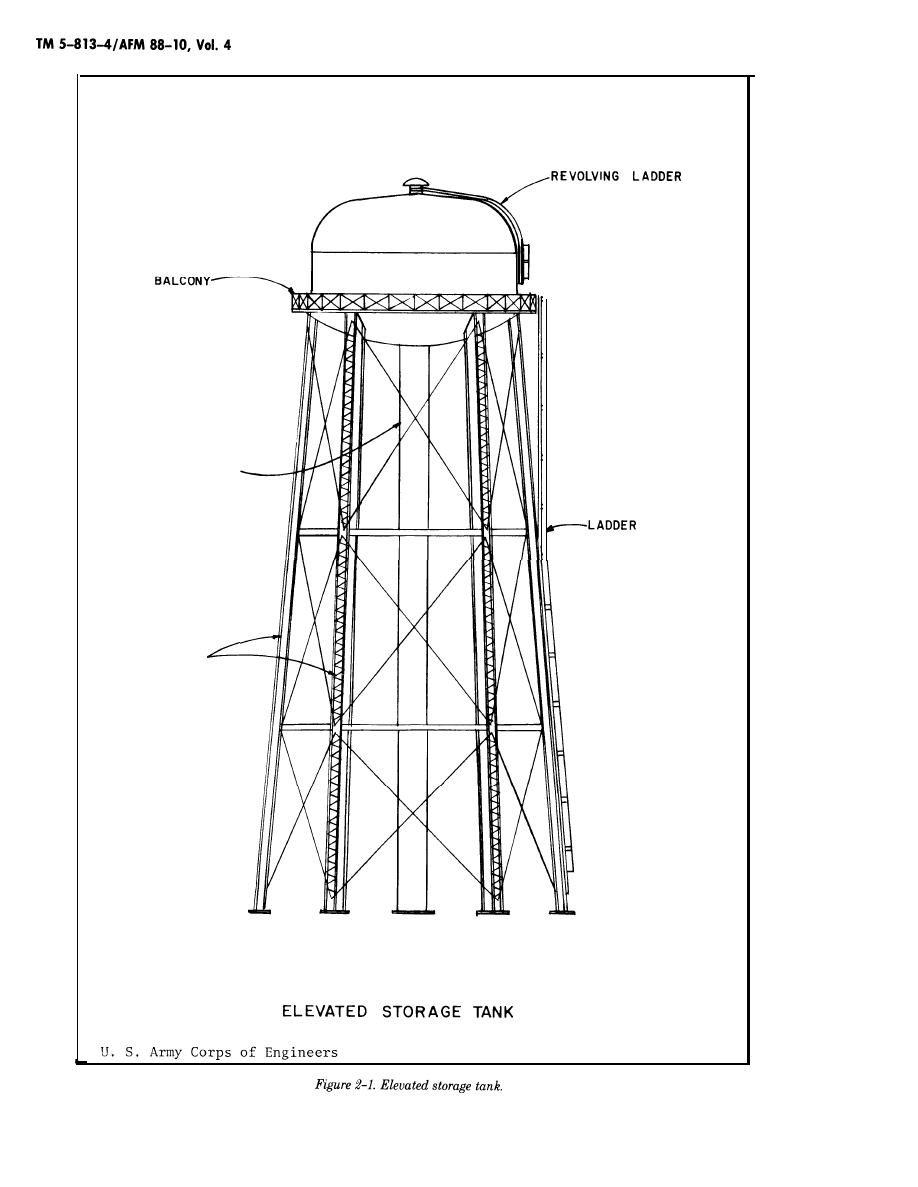
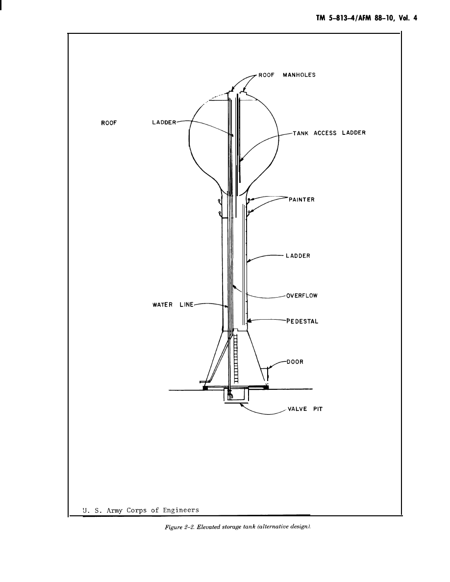
b. Type. The most common types of elevated
storage are elevated steel tanks, and standpipes.
An example of a conventional elevated steel tank
is given in figure 2–1. In recent years, elevated
tanks supported by single pedestals, such as shown
in figure 2–2, have been constructed where esthet-
ic considerations are an important part of the
design process. (See American Water Works Asso-
ciation D100, Standard for Welded Steel Tanks for
Water Storage (app A).)
c. Standpipe. A standpipe is a tall cylindrical
tank normally constructed of steel or reinforced
concrete. Only the portion of the storage volume of
a standpipe that meets the requirements of d
below is considered useful storage for pressure
equalization purposes. The lower portion of the
storage acts to support the useful storage and to
provide a source of emergency water supply.
d. Elevated storage. Elevated storage tanks
should be located in the areas having the lowest
system pressures during intervals of high water
use to be effective in maintaining adequate system
pressures and flows during periods of peak water
demand. These are those of greatest water demand
or those farthest from pump stations. Elevated
tanks are generally located at some distance from
the pump station(s) serving a distribution pressure
level, but not outside the boundaries of the service
area, unless the facility can be placed on a nearby
hill. Additional considerations for siting of elevat-
ed storage are conditions of terrain, suitability of
subsurface soil and/or rock for foundation pur-
poses, and hazards to low-flying aircraft. Elevated
tanks are built on the highest available ground, up
to static pressures of 75 lb/in
2
in the system, so as
to minimize the required construction cost and
heights.
2-1
R /SER
2-2
ACCESS
s’
u
RINGS
PIPE
ELEVATED STORAGE TANK
(ALTERNATIVE DESIGN)
2 - 3

DETERMINATION OF CAPACITY REQUIREMENTS
3-1. Total Storage Requirements
The amount of water storage provided will con-
form to the requirements set forth herein. Request
for waivers to depart from these requirements will
be forwarded to HQDA (DAEN-ECE-G) WASH DC
20314 for Army projects and to HQ USAF/LEEEU
WASH DC 20332 for Air Force projects.
a. All military installations. In general, total
storage capacity, including elevated and ground
storage, will be provided in an amount not less
than the greatest of the following items (para. 3-
2).
Item 1: Fifty percent of the average
total daily domestic requirements plus all
industrial requirements. This will provide
minimum operational storage needed to
balance average daily peak demands on
the system and to provide an emergency
supply to accommodate essential water
needs during minor supply outages of up
to a one-day duration. For the purposes of
this item, essential water needs do not in-
clude the fire demand.
Item 2: The fire demand. The fire
demand is the required fire flow needed to
fight a fire in the facility (including water
required to support fire suppression sys-
tems) which constitutes the largest re-
quirement for any facility served by the
water supply system (calculated IAW TM
5-813-6/AFM 88-10, Vol. 6); plus 50 per-
cent of the average domestic demand rate
plus any industrial or other demand that
cannot be reduced during a fire period.
This amount will be reduced by the
amount of water available under emer-
gency conditions during the period of the
fire (TM 5-813-l/AFM 88-10, Vol. 1).
NOTE
The fire demand quantity must be main-
tained in storage for fire protection at all
times except following a fire fighting opera-
tion when the fire demand quantity would
be depleted. It is recognized that during
daily periods of peak consumption due to
seasonal demands, the amount of water in
storage will be less than full storage ca-
pacity; however, conservation methods
will be instituted to prevent drawdown of
water in storage below the fire demand
quantity. Water storage greater than the
amount determined by the largest of
Items 1, 2, or 3 may be required because
of appropriate adjustments for emergency
water quantity or other applicable factors;
however, this must be substantiated by
actual data on a repeated annual basis
documenting the low storage levels occur-
ring during normal peak demand.
Item 3: The sum of Items 1 and 2
above, that is, the sum of fifty percent of
the average total daily domestic require-
ments, all industrial requirements for an
average day which cannot be shut off
during emergency conditions, and the re-
quired fire demand. The sum of the above
items will be reduced by the amount of
water available in 24 hours under emer-
gency conditions. This will provide maxi-
mum storage where emergency water
supply is a minimum over a 24-hour
period or a supply main outage would sig-
nificantly affect overall supply conditions.
The most economical alternative for meet-
ing the water storage requirements will
be selected in all cases. Installation of ad-
ditional emergency pumping facilities, ad-
ditional water supply connections, drilling
additional wells or other modifications to
the water system which will be more cost
effective than increasing storage capacity
will be developed.
b. Special considerations. The amount of storage
required for plant and special projects will be
based on industrial, domestic, and fire-protection
requirements. Each project will be considered on
the basis of specific need. Hospital storage facili-
ties will be designed in accordance with the latest
edition of the Joint Commission Accreditation
Manual for Hospitals, American Hospital Associa-
tion.
c. Amount of water available under emergency
conditions.
(1)
The amount of water available under emer-
gency conditions is considered to be that available
from auxiliary-powered pumps during electric-cur-
rent outage, from electric-motor-driven pumps
with the largest pump out of service, from one or
more supply mains with the main of greatest ca-
3-1

pacity out of service, or from the water-treatment
plant with one filter out of service. Normally the
capacity of the clearwell storage at the treatment
plant will not be considered part of the required
storage.
(2)
Where the water supply is obtained from
wells, all of which are equipped with standby
power and located within the distribution system,
the emergency supply will be considered as the
quantity available from all but one of the wells.
Where one well has a capacity greater than the
others, that one will be assumed out of service.
Where only 50 percent of the wells have standby
power, the emergency supply will reconsidered as
the quantity available from the wells having
standby power.
(3) Where the project is supplied from a de-
pendable existing source, such as a municipal
system with adequate storage and standby facili-
ties, through supply lines not subject to damage by
floods, high pressure, or other unusual conditions,
the amount of water available under emergency
conditions is that obtainable with the largest con-
nection inoperative.
(4) Where the supply is delivered through a
single supply main, the maximum amount of stor-
age as determined in paragraph 3-la will be pro-
vided.
(5) Where the peak demand for water is avail-
able at adequate residual pressure through two or
more lines while the line having the greatest ca-
pacity is out of service, no storage will be required.
(6) Where the peak demand for water is avail-
able through two or more lines but is not available
if the line having the greatest capacity is out of
service, storage will be required. The quantity of
water available under emergency conditions with
the line of greatest capacity out of service will be
considered in calculating the amount of storage re-
quired.
d. Irrigation requirements. Where irrigation re-
quirements, are justified in arid or semi-arid re-
gions, such irrigation quantities will be included as
an industrial requirement of Items 1, 2, and 3 of
subparagraph 3-la and not as a domestic require-
ment. Water requirements may be increased above
those indicated in TM 5-630 for Army installations
provided that the increased rates can be substanti-
ated by a local or regional Soil Conservation Serv-
ice or recognized local authority as the minimum
rate to sustain lawn-type turf. Irrigation require-
ments for Air Force installations should be sub-
stantiated by a local or regional Soil Conservation
Service or recognized local authority as the mini-
mum rate to sustain lawn-type turf.
3-2. Elevated Storage Capacity
The total elevated storage capacity at all military
installations, except plant and special projects,
should not be less than the amount determined in
paragraph 3-la Item 2, nor less than 50 percent of
the total required storage, unless special condi-
tions prevail which would negate the need for such
storage. For projects with design populations of
10,000 or less, consideration will be given to pro-
viding all elevated storage where the storage will
result in an economical and reliable system. For
projects such as storage depots or aircraft hangers
with deluge sprinkler systems, ground storage res-
ervoirs with booster pumps will generally be the
more economical method of supplying large vol-
umes of water for fire protection. Elevated tanks
will normally be provided for initial sprinkler
demand in storage warehouses. Water storage can
be most economically provided by constructing
ground storage reservoirs on high ground. Howev-
er, in the absence of suitable terrain, elevated
tanks will be required.
3-3. Economic Analyses
a. General. Economic analyses of storage re-
quirements could guide decisions on the imple-
menting or postponing of expenditures for new
transmission mains, the constructing of booster
pumping facilities to increase transmission main
capacities instead of adding new mains, the in-
creasing of the quantity of storage within a distri-
bution system, and the providing of elevated stor-
age or ground storage with booster pumping facili-
ties.
b. Distribution storage. Distribution storage is in-
tended to meet peak flow requirements or emer-
gency needs, maintain system pressures, and thus
reduce the required capacities of the treatment
plant and pump stations. The design of storage fa-
cilities, in accordance with paragraphs 3-1 and 3–
2, will be determined by feasibility studies which
take into account all engineering, economic,
energy, and environmental factors. Analysis will
be in accordance with AFR 178-1 for Air Force
projects and AR 11-28 for Army projects.
3 - 2

DESIGN AND CONSTRUCTION OF WATER STORAGE FACILITIES
4-1. Reservoir Covers
All treated water reservoirs must be covered to
prevent contamination by dust, birds, leaves, and
insects. These covers will be, insofar as possible,
watertight at all locations except vent openings.
Special attention should be directed toward
making all doors and manholes watertight. Vent
openings must be protected to prevent the entry of
birds and insects; and vent screens should be kept
free of ice or debris so that air can enter or leave
the reservoir area as temperature and water levels
vary. All overflows or other drain lines must be
designed so as to eliminate the possibility of flood
waters or other contamination entering the reser-
voir. Reservoir covers also protect the stored water
from sunlight, thus inhibiting the growth of algae.
Further prevention of algae growth or bacterial
contamination, due to the depletion of the chlorine
residual, can be obtained by maintaining sufficient
flow through the reservoir so that water in the
reservoir does not become stagnant. Minimal flows
through the reservoir also help to prevent ice
buildup during cold periods.
4-2. Altitude Valves
All storage tanks will be provided with altitude
valves to prevent overflows. These altitude valves
will be installed in concrete pits having provision
for draining either by gravity or pumping. Drains
will not be connected to sanitary sewers. Every
precaution will be taken to prevent the collection
of water from any source in valve pits.
4-3. Instrumentation and Control
Storage measurements are used for monitoring, in-
ventory, and system controls. Elevated and ground
storage measurements will be made by pressure
sensitive instruments directly connected by static
pressure lines at points of no flow. Underground
storage measurements will be made by air bubbler
back pressure sensitive instruments or by float ac-
tuated instruments. The direct pressure measure-
ments of elevated tanks will be suppressed to read-
out only the water depth in the elevated bowl.
High and low level pressure sensitive switches will
be used for alarm status monitoring and for pump
cut-off controls. Intermediate level switches, pres-
sure or float actuated, will be used for normal
pump controls. Metering, monitoring, and pump
control requirements at some point remote from
storage must use level telemetering instruments.
Telemetering over local direct wire communica-
tions facilities will use 15 second time duration or
impulse duration telemetering equipment. Teleme-
tering over leased telephone lines often requires
the introduction of a tone transmitter and receiver
keyed by the time-impulse telemetering equip-
ment. High storage level will initiate the shut-
down of supply pumping units and actuation of an
overflow alarm in that order. Low storage level
will initiate startup of supply pumping or well
pumping units or distribution pumping unit shut-
down.
4-4. Disinfection
Potable water storage facilities, associated piping,
and ancillary equipment must be disinfected
before use. Disinfection will be accomplished fol-
lowing procedures and requirements of American
Water Works Standard D105. In no event will any
of the above equipment or facilities be placed in
service prior to verification by the supporting med-
ical authority, by bacteriological tests, that disin-
fection has been accomplished.
4-5. Design Analyses
The design analyses will set forth the basis by
which storage capacities and locations have been
determined. Except where standard specifications
for tanks or towers are used, the analyses will
show the method by which the structural adequa-
cy of the unit has been determined.
4 - 1

A-1. Government Publications
a. Department of the Army.
AR 11-28 . . . . . . . . . . . . . . . . . . . . . . . . . . . . . . . . . . . . . . . . . . . . . . . . . . . . . . . . . . . . . . . . . . . . Economic Analysis and
source Management.
TM 5-630 . . . . . . . . . . . . . . . . . . . . . . . . . . . . . . . . . . . . . . . . . . . . . . . . . . . . . . . . . . . . . . . . . . . Repairs and Utilities,
Land Management.
b. Department of the Air Force.
AFR 178-1 . . . . . . . . . . . . . . . . . . . . . . . . . . . . . . . . . . . . . . . . . . . . . . . . . . . . . . . . . . . . . . . . . Economic Analysis and
source Management.
c. Departments of the Army and Air Force.
TM 5-813-l/AFM 88-10, Vol. 1 . . . . . . . . . . . . . . . . . . . . . . . . . . . . Water Supply: Sources
Program Evaluation for Re-
Ground Maintenance and
Program Evaluation for Re-
and General Considerations.
TM 5-813-5/AFM 88-10, Vol. 5 . . . . . . . . . . . . . . . . . . . . . . . . . . . . Water Supply: Water Distribution Systems.
TM 5-813-6/AFM 88-10, Vol. 6 . . . . . . . . . . . . . . . . . . . . . . . . . . . . Water Supply: Water Supply for Fire Protection.
TM 5-813-7/AFM 88-10, Vol. 7 . . . . . . . . . . . . . . . . . . . . . . . . . . . . Water Supply: Water Supply for Special Projects.
A-2. Nongovernment Publications
Joint Commission on Accreditation of Hospitals, 875 N. Michigan Avenue, Chicago, Illinois 60661
Accreditation Manual for Hospital, 1979
American Water Works Association Standard, (AWWA) American Water Works Association, 6666 W.
Quincy Avenue, Denver, Colorado 80235
Standards:
D100 . . . . . . . . . . . . . . . . . . . . . . . . . . . . . . . . . . . . . . . . . . . . . . . . . . . . . . . . . . . . . . . . . . . . . . . . . . . . Welded Steel Tanks for Water Storage.
D105 . . . . . . . . . . . . . . . . . . . . . . . . . . . . . . . . . . . . . . . . . . . . . . . . . . . . . . . . . . . . . . . . . . . . . . . . . . . . Disinfection of Water Storage Facilities.
A-1
B-1. General
The following typical design examples illustrate procedures to be followed in the determination of total
capacity requirements for water storage facilities at Army or Air Force installations.
B-2. Example No. 1: Communications base; permanent construction
a. Effective population.
b. Water source. Wells on post; average yield 150 gal/rein each.
c. Treatment. Chlorination.
e. Well requirements.
Total well yield: Assuming 24-hour/day well operation, one well has sufficient yield to meet the required
daily demand rate of 130 gal/rein. However, for firm production capability, it is necessary to have two
wells, each capable of 130 gal/rein.
Minimum pump requirement: The dependable
output
of the source of Supply, i.e. the two wells, must be
equal to, or greater than, the required
daily demand. ‘l?hus, each well Should be
equipped with a 150-gal/
pump. Two reliable sources of electric service should be provided, or one pump should be equipped with
both an electric motor and standby internal combustion engine. The size and number of distribution
pumps required are related to the type, size, and location of storage facilities. Provisions of elevated stor-
age will reduce the required pump capacity.
f. Storage requirement.
.
B-1
g. Water main sizes. The water distribution system will have mains of adequate size to meet peak domes-
tic demand (see TM 5-813-l/AFM 88-10, Vol. 1) and pressure requirements at all locations. General design
criteria for water mains is given in TM 5-813-5/AFM 88-10, Vol. 5.
B-3.
a.
b.
c.
d.
Example No. 2: Permanent camp.
Effective population.
Nonresident: Negligible
Resident: 20,000
Water source. Surface supply from river.
Treatment. Coagulation, flocculation, sedimentation, filtration, and chlorination.
Required daily demand and fire flows.
e.
B - 2
B-4. Example No. 3: A barracks, Type 1, Fire resistive construction unsprinkled facilities, floor area 125,000 sq. ft.
B - 3

B - 4

BIBLIOGRAPHY
American Iron and Steel Institute. Steel
Tanks for Liquid Storage. New York, New York:
American Iron and Steel Institute (no date given).
American Water Works Association.
AWWA Manual M8, A Training Course in Water
Distribution. Denver, Colorado: American Water
Works Association, 1962.
Brock, Dan A. “Determination of Opti-
.
mum Storage in Distribution System Design.”
Journal of the American Water Works Association
(1963) 55:1027.
Clark, J. W., Warren Viessman, Jr., and
M. J. Hammer. Water Supply and Pollution Con-
trol. 2nd ed. Scranton, Pennsylvania: International
Textbook Company, 1971.
Fair, G. M., J. C. Geyer, and D. A. Okun.
Elements of Water Supply and Wastewater Dispos-
al. New York, New York: John Wiley & Sons, Inc.,
1971.
Lorenz, J. B. “Storage Considerations for
Water Distribution Systems,” a paper presented at
the Engineering Institute for Water Storage Facili-
ties. Madison, Wisconsin: University of Wisconsin-
Extension, October 16, 1965.
Proudfit, D. P. “Storage Consideration in
Relation to Source, Capacity and Peak Demands,”
a paper presented at the Sanitary Engineering In-
stitute. Madison, Wisconsin: University of Wiscon-
sin, March 1, 1965.
Proudfit, D. P. and J. B. Lorenz. “Param-
eters for Determining Adequacy of Storage Capac-
ity for Large and Small Systems on the Basis of
Peak Demands and Fire Flow Requirements,” Pro-
ceedings AWWA 95th Annual Conference, Minne-
apolis, Minn., June 9-12, 1975, Paper No. 7-3.
Denver, Colorado: American Water Works Associa-
tion, 1975
0
Twort, A. C., R. C. Heather, and F. M.
Law. Water Supply, 2nd ed. New York, New York:
American Elsevier Publishing Company, Inc., 1974.
—
B-5
The proponent agency of this publication is the Office of the Chief of Engineers,
United States Army. Users are invited to send comments and suggested improve-
ments on DA Form 2028 (Recommended Changes to Publications and Blank Forms)
direct to HQDA (DAEN-ECE-G), WASH DC 20314-1000.
By Order of the Secretaries of the Army and the
Air Force:
Official:
ROBERT M. JOYCE
Major General, United States Army
The Adjutant General
Official:
JAMES H. DELANEY, Colonel, USAF
JOHN A. WICKHAM, JR.
General, United States Army
Chief of Staff
CHARLES A. GABRIEL, General, USAF
Chief of Staff
Director of Administration
-
Distribution:
Army: To be distributed in accordance with DA Form 12-34B, requirements for TM 5-800 Series: Engi-
neering and Design for Real Property Facilities.
Air Force: F.
B - 7
Wyszukiwarka
Podobne podstrony:
tm5 814 1waste h2o pump stat
operator urzadzen przemyslu szklarskiego 813[02] z2 07 n
812 813
operator urzadzen przemyslu ceramicznego 813[01] z2 07 u
operator urzadzen przemyslu szklarskiego 813[02] z2 03 u
operator urzadzen przemyslu szklarskiego 813[02] z2 05 n
operator urzadzen przemyslu ceramicznego 813[01] o1 05 n
operator urzadzen przemyslu szklarskiego 813[02] z2 05 u
operator urzadzen przemyslu szklarskiego 813[02] z2 01 n
conceptual storage in bilinguals and its?fects on creativi
operator urzadzen przemyslu ceramicznego 813[01] z1 01 n
operator urzadzen przemyslu ceramicznego 813[01] z2 06 n
operator urzadzen przemyslu ceramicznego 813[01] o1 06 n
Shed plan storage
TM5 90szlif
tm5
operator urzadzen przemyslu ceramicznego 813[01] z2 08 u
operator urzadzen przemyslu ceramicznego 813[01] z2 08 n
więcej podobnych podstron