
Initial Print Date: 01/09
Table of Contents
Subject
Page
Unlocking and Locking the Vehicle . . . . . . . . . . . . . . . . . . . . . . . . . . . . . . .5
Central Locking System Circuit Diagram . . . . . . . . . . . . . . . . . . . . . . . . . . .8
Unlocking/locking the Vehicle . . . . . . . . . . . . . . . . . . . . . . . . . . . . . . . . . .12
Functional Procedure . . . . . . . . . . . . . . . . . . . . . . . . . . . . . . . . . . . . . . .13
Central locking button . . . . . . . . . . . . . . . . . . . . . . . . . . . . . . . . . . .14
Mechanical Key/Spare Key . . . . . . . . . . . . . . . . . . . . . . . . . . . . . . . . . .15
Driver’s-door lock barrel . . . . . . . . . . . . . . . . . . . . . . . . . . . . . . . . . .15
Locking Button on Vehicle Doors . . . . . . . . . . . . . . . . . . . . . . . . . . . . .16
Car Access System 4 . . . . . . . . . . . . . . . . . . . . . . . . . . . . . . . . . . . . . . .16
Junction Box Electronics Module . . . . . . . . . . . . . . . . . . . . . . . . . . . .16
Exterior trunk button . . . . . . . . . . . . . . . . . . . . . . . . . . . . . . . . . . . . .17
Interior trunk button in the A-pillar . . . . . . . . . . . . . . . . . . . . . . . . .18
Closing the trunk . . . . . . . . . . . . . . . . . . . . . . . . . . . . . . . . . . . . . . . .18
Automatic locking (personal profiles) . . . . . . . . . . . . . . . . . . . . . .18
Unlocking after a crash . . . . . . . . . . . . . . . . . . . . . . . . . . . . . . . . . . .18
Selective unlocking . . . . . . . . . . . . . . . . . . . . . . . . . . . . . . . . . . . . . .18
Central Locking Button . . . . . . . . . . . . . . . . . . . . . . . . . . . . . . . . . . . . .19
Components of the Central Locking System . . . . . . . . . . . . . . . . . . . . .20
Car Access System 4 . . . . . . . . . . . . . . . . . . . . . . . . . . . . . . . . . . . . . . .20
F01 Central Locking System
Revision Date:

Subject
Page
Junction Box Electronics Module . . . . . . . . . . . . . . . . . . . . . . . . . . . . .20
Driver’s-door lock barrel . . . . . . . . . . . . . . . . . . . . . . . . . . . . . . . . . .22
Trunk locking barrel . . . . . . . . . . . . . . . . . . . . . . . . . . . . . . . . . . . . . .22
Center-lock button . . . . . . . . . . . . . . . . . . . . . . . . . . . . . . . . . . . . . . .23
Central Locking Drive Units . . . . . . . . . . . . . . . . . . . . . . . . . . . . . . . . . .23
Central locking drive units in the doors . . . . . . . . . . . . . . . . . . . . .23
Trunk central locking drive (trunk lock) . . . . . . . . . . . . . . . . . . . . .23
Automatic soft-close drive for the trunk . . . . . . . . . . . . . . . . . . . .24
Fuel filler flap central locking drive . . . . . . . . . . . . . . . . . . . . . . . . .24
Manually releasing the fuel filler flap . . . . . . . . . . . . . . . . . . . . . . .24
Manually Unlocking the Ttrunk . . . . . . . . . . . . . . . . . . . . . . . . . . . . . . .25

Subject
Page
BLANK
PAGE

4
F01 Central Locking System
Central Locking System
Model: F01/F02
Production: From Start of Production
After completion of this module you will be able to:
• Locate and identify components of the central locking system
• Understand the operation of the central locking system

Unlocking and Locking the Vehicle
The central locking system makes it possible to unlock or lock the vehicle. It is fitted as
standard equipment and relates to all vehicle doors, the fuel filler flap and the trunk.
The central locking can be operated via the following components:
• ID transmitter
• Driver’s-door lock barrel (door lock)
• Central-lock button
• Trunk lock barrel
• Exterior trunk button
• Interior trunk button in the A-pillar
• Outside door handle * (outside door handle electronics/Car Access System)
• Central locking button in the trunk lid *.
* Component of the Comfort Access option.
The central locking system in the F01/F02 is based on the central locking system as it is
already known in, for instance, the E90 or E70. The function of the central locking
system is basically divided between three control units.
The Car Access System has overall control. The Car Access System is aware of the sta-
tuses of the central locking system. Therefore it is the Car Access System which causes
the unlocking, locking and central locking of the vehicle.
The junction box electronics module executes the request to unlock or lock the vehicle.
Note: The Car Access System is now entering its fourth control-unit genera-
tion and contains the functions of its predecessor.
With Car Access System 4, Comfort Access functionality is now also
integrated into this control unit. This means that, on the F01/F02 there
is no separate control unit for Comfort Access.
It is possible to unlock and lock the vehicle actively or passively.
• Active means that the vehicle can be opened after it has been unlocked by a press
of the button on the ID transmitter. The vehicle can be locked by pressing the Lock
button after the doors have been closed.
Note: The vehicle can only be locked with the driver’s door closed.
5
F01 Central Locking System
Introduction

Passive locking and unlocking requires the option Comfort Access.
• Passive means the vehicle is unlocked when the outer door handle is grasped,
provided the ID transmitter is located within a radius of no more than approxiamately
1.5 meters from the vehicle. The locking function is triggered by pressing on the
sensitive area on the outer door handle.
The trunk is fitted with the automatic soft-close function as standard. With the automatic
soft-close function, it is sufficient to gently press the trunk into the trunk lock. As soon as
the locking pawl reaches the pre-locking position, automatic soft-close fully closes the
trunk. The locking pawl is then located in the main locking position.
An alternative is automatic soft-close, the automatic soft-close function is available for all
vehicle doors. When equipped with the automatic soft-close function, the vehicle door
needs only to be gently pulled or pushed into the lock. The automatic soft-close function
then completely closes the door.
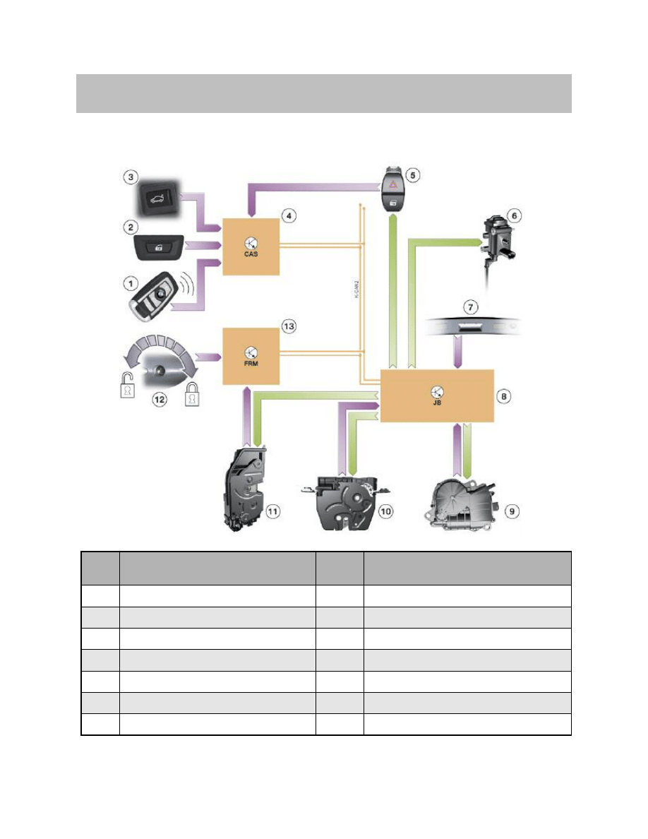
The Car Access System (4) evaluates the signal from the ID transmitter (1) and requests
the unlocking or locking of the vehicle. The junction box electronics module (8) executes
the requests.
The lock barrel (12) in the driver's door is used for mechanically unlocking or locking the
door. The footwell module (10) evaluates the movement (status of Hall sensors) of the
lock barrel and the status of the door contacts.
6
F01 Central Locking System
Input/output Central Locking
7
F01 Central Locking System
System Overview
Index
Explanation
Index
Explanation
1
ID transmitter
8
Junction box electronics module (JB)
2
Central locking button
9
Automatic soft-close drive in the trunk lock
3
Interior trunk button in the A-pillar
10
Trunk central locking system
4
Car Access System 4 (CAS 4)
11
Lock (4x) in vehicle doors
5
Center-lock button
12
Driver's-door lock barrel
6
Central locking, fuel filler flap
13
Footwell module (FRM)
7
Exterior trunk button
K-CAN2
Bodyshell CAN
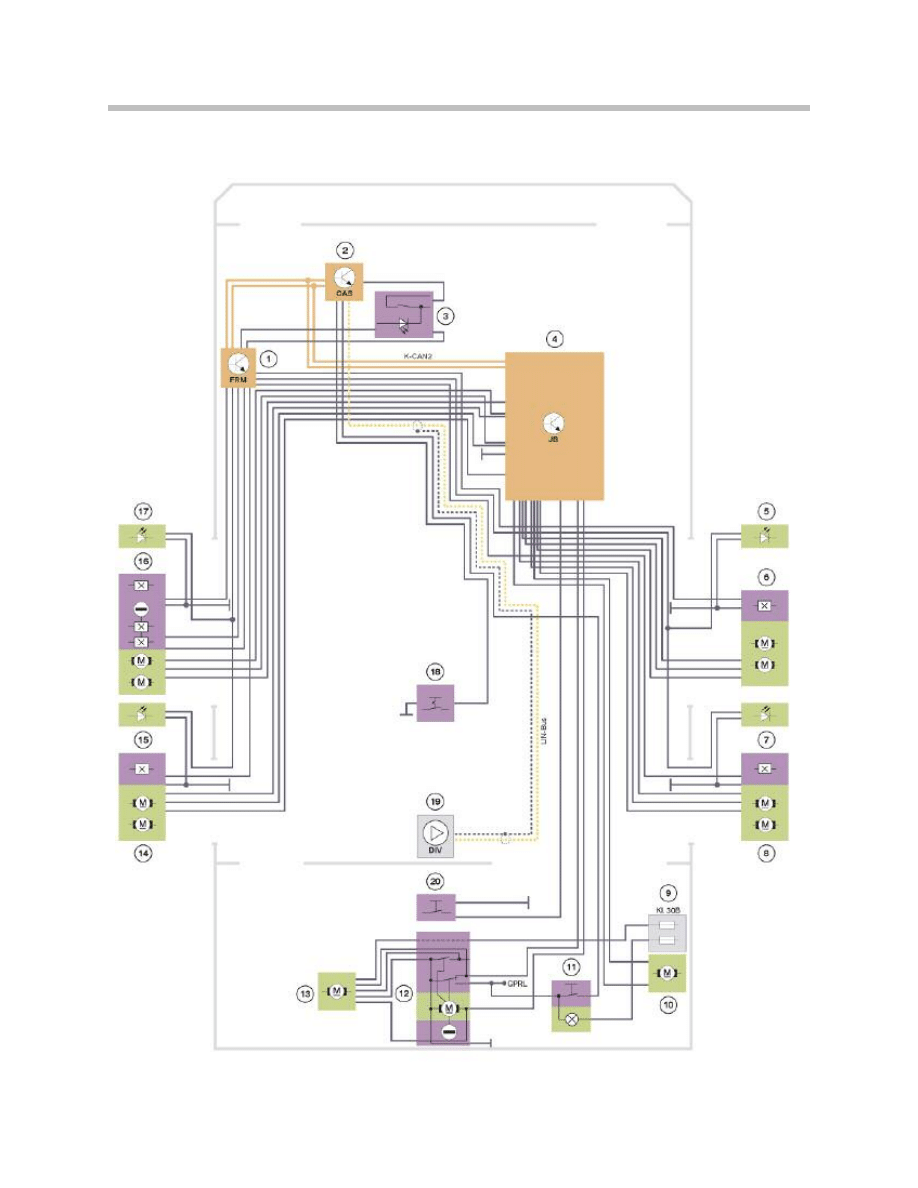
Central Locking System Circuit Diagram
8
F01 Central Locking System
K-CAN signals at Car Access System 4
9
F01 Central Locking System
Index
Explanation
Index
Explanation
1
Footwell module (FRM)
13
Automatic soft-close drive in the trunk lock
2
Car Access System (CAS)
14
Rear, driver’s side central locking system
3
Center-lock button
15
Rear, driver’s side illuminated entry system
4
Junction box electronics module (JB)
16
Hall sensors for lock barrel, door contact,
driver’s-door central locking system
5
Front-passenger-door illuminated entry system
17
Driver’s-door illuminated entry system
6
Door contact, central locking,
front passenger door
18
Valet switch
7
Rear, passenger-side illuminated entry system
19
Remote control receiver in diversity module
8
Door contact, central locking,
rear passenger side
20
Exterior trunk button
9
Fuse in the luggage compartment
power distribution box
K-CAN2
Bodyshell CAN2
10
Central locking, fuel filler flap
Kl. 30B
Terminal 30, basic operation
11
Central locking button
LIN-Bus
Local Interconnect Network bus
12
Trunk lock central locking system
GPRL
Luggage compartment light
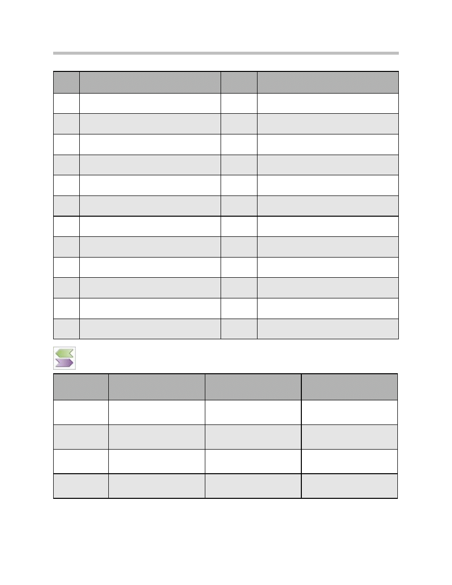
In/out
Information
Source/sink
Function
In
Crash signal
Crash sensor > Advanced Crash
Safety Management
Unlock central locking in the
event of a crash
In
Driving speed
Wheel-speed sensor >
Integrated Chassis Management
Lock central locking from a
defined driving speed
Out
Hall sensor status, driver's-door
lock barrel
Driver's-door lock barrel >
Footwell module
Comfort opening of vehicle
Out
Hall sensor status, driver's-door
lock barrel
Driver's-door lock barrel >
Comfort closing of vehicle
Footwell module

The radio signal from the ID transmitter is received by the rear window antenna. The
remote control receiver integrated in the diversity module (19) forwards the signal to the
Car Access System (2). After the signal has been successfully checked, the Car Access
System issues a request for control of the central locking system. The Car Access
System is the master control unit for the central locking system.
The junction box electronics module (4) executes the unlocking or locking of the vehicle.
The footwell module (1) evaluates the status of all door contacts (6, 8, 14 and 16).
It communicates the current status on the KCAN2. This means, for example, that the Car
Access System is able to prevent locking when the driver’s door is open.
The status of the center-lock button (3) is evaluated by the Car Access System and
communicated over the K-CAN2. Depending on the status, the junction box electronics
module activates central locking. The junction box electronics modules is also responsi-
ble for registering the status and activating central locking in the trunk.
The junction box electronics module is also responsible for controlling the fuel filler flap
(10).
The footwell module evaluates the signals from the Hall sensors for the lock barrel (16)
and makes this information available on the K-CAN2.
With this information, the Car Access System knows the status of the door lock in the dri-
ver’s door. This is important if a request is issued to unlock or lock the vehicle using the
ID transmitter, for example.
The central locking button is integrated in the underside of the trunk and is part of the
Comfort Access option.
10
F01 Central Locking System

11
F01 Central Locking System
NOTES
PAGE
Unlocking/locking the Vehicle
The vehicle unlocking/locking procedure is initiated by the following system
components:
• ID transmitter
• Mechanical key/spare key
• Exterior trunk button (only unlocks the trunk)
• Central-lock button
• Interior trunk button on the A-pillar (only unlocks the trunk)
• Outside door handle *
• Central locking button * trunk.
* Vehicle equipment for Comfort Access.
The central locking system activates the following system components:
• Central locking, driver’s and front passenger door
• Central locking, rear doors
• Central locking, fuel tank
• Trunk central locking system (with automatic soft-close drive).
The following example shows the signal path when the trunk is unlocked.
12
F01 Central Locking System
Functions

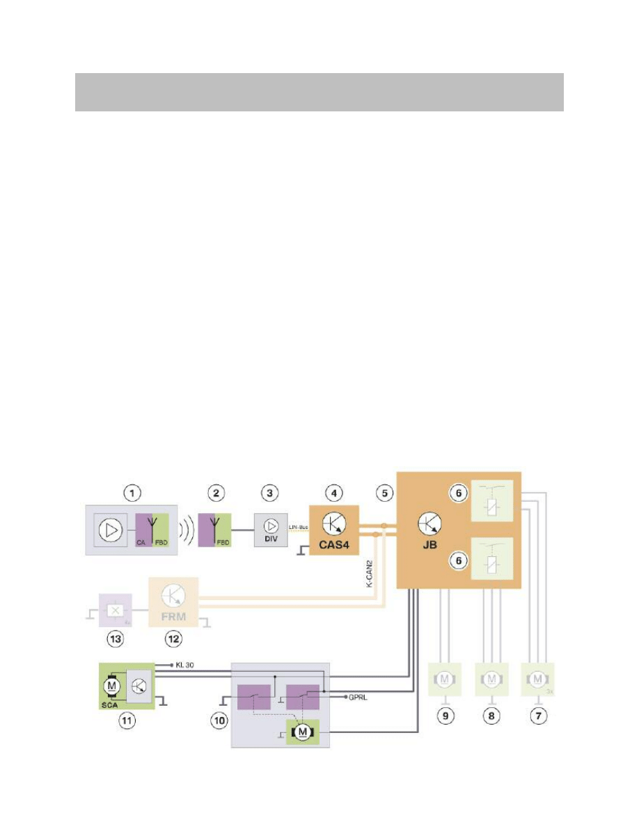
Functional Procedure
Unlocking
Pressing the Unlock button on the ID transmitter causes an encrypted remote control
signal to be transmitted. The antenna in the rear window forwards the remote control sig-
nal to the diversity module. The diversity module remote control receiver demodulates,
processes and then sends the signal to the Car Access System on the LIN bus.
If the vehicle is in sleep mode, the remote control receiver wakes up the Car Access
System via the LIN bus for reduced-consumption operation. This allows the Car Access
System to receive the request which was sent out by the ID transmitter. The ID transmit-
ter has already been checked in the remote control receiver. If the result of the check is
positive, the remote control receiver forwards the request via the LIN bus. If the request is
authorized, the Car Access System wakes up the vehicle and causes the vehicle to
unlock. The Car Access System thereby gives the junction box electronics module per-
mission to unlock the central-locking drive.
The junction box electronics module then activates the relay and power output stages
and triggers the unlocking of the vehicle.
Note: The Car Access System is responsible for communication over the LIN
bus. This means that the diversity module only passes on a LIN bus sig-
nal when instructed to do so by the Car Access System 4. This applies to
vehicles not currently in sleep mode.
13
F01 Central Locking System
Index
Explanation
Index
Explanation
1
ID transmitter
8
Central locking, driver's door
2
Rear window antenna
9
Central locking, fuel filler flap
3
Remote control receiver in diversity module
10
Trunk central locking system
4
Car Access System 4 (CAS 4)
11
Trunk automatic soft-close
5
Junction box electronics module (JB)
12
Footwell module
6
Relay for central locking
13
Door contacts
7
Central locking, front passenger door
and rear doors

Locking
The vehicle can only be locked once the footwell module has evaluated the door con-
tacts and the Car Access System 4 has reported that the driver’s door is closed.
The further signal progression for locking the vehicle corresponds analogously to the sig-
nal progression of the unlocking procedure.
During the vehicle locking process, all central locking drives are moved into the “Lock”
position. The central-locking drives in the doors are additionally moved into the “centrally-
locked” position. Following the central arrest procedure, the locking buttons in the doors
are mechanically separated from the central locking drive system.
The vehicle can now no longer be unlocked using the locking buttons in the doors.
Note: The trunk can either be locked manually or using automatic trunk actua-
tion.
Central locking button
The central locking button can be used to lock and centrally lock all vehicle doors.
The central locking button is located on the underside of the trunk and can therefore only
be used with the trunk open.
Additional information is presented under the Central locking button section, which fol-
lows.
Center-lock Button
The vehicle can be locked/unlocked with the center-lock button.
If the center-lock button is not being pressed, the junction box electronics module
receives a high signal (battery voltage approxiamately 12 V). The high signal changes
to a low signal (approximately 0 V) as soon as the center-lock button is pressed.
The junction box electronics module evaluates the change from the high signal to the low
signal and locks/unlocks the vehicle.
In order for locking or unlocking to take place, the driver’s door and front passenger door
must be closed.
14
F01 Central Locking System

Mechanical Key/Spare Key
The mechanical key/spare key is used to unlock/lock the driver’s door. Should the ID
transmitter fail, e.g. if the battery is flat, it is still possible to access or lock the vehicle.
Driver’s-door lock barrel
The footwell module evaluates the Hall sensors for the lock barrel in the driver’s door.
The Car Access System 4 is informed of the change in status via the K-CAN2.
The Car Access System 4 enables the vehicle unlocking/locking procedure. The junction
box electronics module triggers the unlocking/ locking of the vehicle.
The normal procedure for unlocking or locking using the mechanical key occurs within a
period of approxiamately 20 ms to 1 second. Evaluation of the lock barrel Hall sensors
occurs within this period of time.
Note: Turning the mechanical key in the driver’s-door lock barrel too quickly or
slowly, means that only the driver’s door will be mechanically unlocked
or locked. In such situations, the central locking system does not oper-
ate.
Trunk lock
The trunk lock can be unlocked by using the mechanical key in the lock barrel, and then
opened.
Note: If the anti-theft alarm system is fitted, unlocking the trunk may trigger an
alarm.
To close the trunk, the trunk must be pushed into the trunk lock. As soon as the locking
pawl reaches the pre-locking position, automatic soft-close begins and closes the trunk.
Note: In the F01, the trunk lock is pulled closed via an automatic soft-close
drive. Slamming the trunk closes the trunk so quickly that automatic
soft-close is not activated.
15
F01 Central Locking System

Locking Button on Vehicle Doors
All four doors can be mechanically locked separately with the locking button.
The inside door handle of the door to be unlocked must be pulled twice before the door
will unlock.
However, the junction box electronics module does not activate central locking.
If the vehicle is centrally locked, the locking knobs are mechanically disconnected from
the lock. It is thus no longer possible to unlock the vehicle either via the locking knobs or
by pulling twice on the door handle. On vehicles with an anti-theft alarm system, this also
activates the system.
Car Access System 4
As soon as the Car Access System 4 receives the signal from the remote control receiver,
it checks whether the ID transmitter is valid and belongs to the vehicle. Only if the check
is successful will the Car Access System 4 forward the request to the central locking.
The check, also referred to as authentication, takes a few milliseconds. As the master
control unit of the central locking system, the Car Access System 4 grants authorization
for control of the central locking system.
The junction box electronics module receives the enable via the K-CAN2.
Junction Box Electronics Module
The junction box electronics module is the The trunk central locking system is activated
slave control unit which unlocks/locks the directly via a power output stage. entire vehicle.
The unlocking/locking relays are located in the junction box electronics module. The fol-
lowing relays are activated:
• Relay for unlocking/locking central locking
– Driver’s door.
• Relay for unlocking/locking central locking
– Rear doors
– Front passenger door
– Fuel filler flap.
Footwell Module
The footwell module monitors the Hall The request to lock the vehicle, for example, is
sensors of the door contacts. Opening or not executed while the driver’s door is open.
closing a door causes a change in status of the door contact in question to occur.
The junction box electronics module receives the current status of the door contacts from
the footwell module via the K-CAN2. The junction box electronics module passes the
status of the door contacts on to the Car Access System 4.
16
F01 Central Locking System
Unlocking the Trunk
The trunk can be unlocked via the ID transmitter and the exterior or interior trunk button,
and then opened.
ID transmitter
The ID transmitter is used to trigger the unlocking of the trunk by means of a brief
(approximately 500 ms) press on the trunk symbol button.
The junction box electronics module executes the unlocking of the trunk.
The motor in the trunk lock is activated via the power output stage in the junction box
electronics module.
Note: If the vehicle is fitted with the automatic trunk actuation option,
the trunk symbol button must be pressed and held for longer than
1.2 seconds.
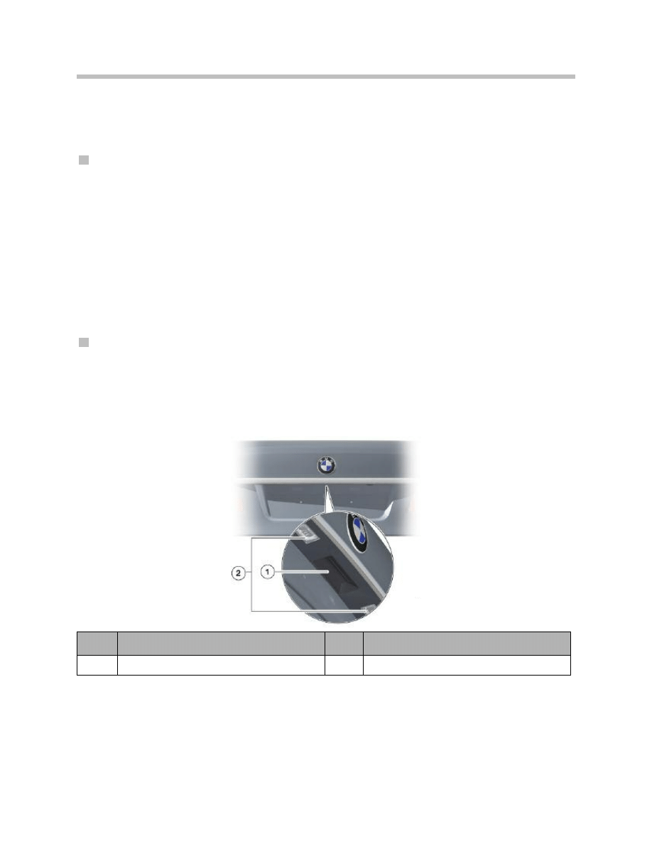
Exterior trunk button
As soon as the vehicle is unlocked, the trunk can be opened with the exterior trunk but-
ton in the trunk. The button switches to ground when the exterior trunk button is pressed.
The button is monitored by the junction box electronics. When the signal of the button
changes to low, the trunk is unlocked and can be opened.
17
F01 Central Locking System
Index
Explanation
Index
Explanation
1
Exterior trunk button
2
Liscense plate light

Interior trunk button in the A-pillar
As soon as the vehicle is unlocked, the trunk can be unlocked and opened by pressing
the interior trunk button.
The button is integrated into the A-pillar and switches to ground.
The Car Access System evaluates the button and sends the signal for the junction box
electronics module over the K-CAN2. The junction box electronics module evaluates the
message and triggers the trunk to unlock.
Closing the trunk
Gently pressing the trunk into the trunk lock triggers the automatic soft-close drive.
A microswitch in the trunk lock is activated by the locking pawl being located in the pre-
locking position. The drive electronics for automatic soft-close assess the change in sta-
tus as a starting signal.
The drive then pulls the rotary striker closed via a Bowden cable. As soon as the locking
pawl engages in the main locking position, the automatic soft-close drive is stopped.
Note: The automatic soft-close drive serves to ensure that the trunk closes
both safely and securely.
Special Functions
Automatic locking (personal profiles)
At speeds in excess of 16 km/h (10 mph), the vehicle locks automatically. The speed sig-
nal is supplied by the Integrated Chassis Management.
The vehicle is unlocked in connection with Comfort Access as soon as terminal 15 is
switched off.
Note: Various functions of the central locking system can be individually cus-
tomized using “personal profiles”. Refer to the Owner’s Handbook for
further information.
Unlocking after a crash
A locked central locking system is unlocked as soon as the Car Access System 4
receives a crash message from the advanced crash safety management.
After this crash message is received, the central locking controls are blocked.
The controls are only enabled again after Advanced Safety Crash Management (ASCM)
stops sending the crash message or if, after 10 seconds, the crash message is no longer
received.
Selective unlocking
With corresponding coding, the vehicle can also be unlocked selectively. In this case, ini-
tially the driver’s door is unlocked. The rest of the vehicle is unlocked in response to a
renewed unlock request.
18
F01 Central Locking System
Central Locking Button
A new function for the central locking system is the ability to activate central locking from
the trunk.
The central locking button is located on the underside of the trunk. Whether or not the
button is present depends on which equipment is installed on the vehicle.
Pressing the central locking button locks and centrally locks all vehicle doors.
Note: The central locking button is only accessible with the trunk open.
The button status is evaluated by the Car Access System. If the vehicle is in sleep mode,
it must first be woken up.
The Car Access System recognizes that the central locking button has been pressed and
locks and centrally locks the car as appropriate.
19
F01 Central Locking System
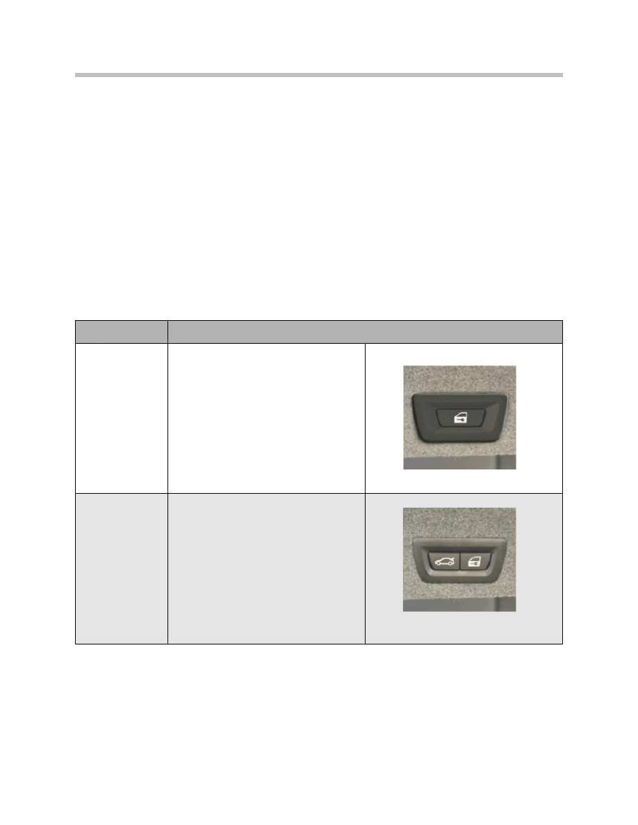
Option
Central locking button
Comfort Access
(CA)
Central locking button
Automatic Trunk
Actuation
(HKL)
Button for HKL actuation is located next to
central locking button

Components of the Central Locking System
Footwell Module
The footwell module is installed at the left-hand A-pillar. It evaluates the status of the
door contacts and reads in the Hall sensor signals of the lock barrel in the driver’s door
and transfers the information via the K-CAN2 to the junction box electronics module or
Car Access System 4.
Car Access System 4
The Car Access System 4 is installed on the right, above the steering column. It
assumes the master function for the central locking system. The Car Access System 4
has the exclusive system authorization and is simply supported by the other control
units.
The Car Access System 4 also registers the status of the center lock button. The Car
Access System 4 activates central locking, depending on the status of the central lock-
ing system. Briefly pressing the center lock button triggers the vehicle to lock or unlock.
The Car Access System evaluates the status of the interior trunk button on the A-pillar
and the central locking button on the trunk.
Junction Box Electronics Module
The junction box electronics module is plugged into the front power distribution box.
Note: The power distribution box and the junction box electronics module are
two separate components. This must be borne in mind when performing
service work.
The junction box electronics module contains the relays for activating the central locking
drive units.
The trunk central locking is activated via a power output stage in the junction box elec-
tronics module.
The status of the exterior trunk button is read by the junction box electronics module
and this information is passed on to the Car Access System 4.
The automatic soft-close drive and the remote control receiver are supplied with power
by the rear power distribution box.
Controls
The central locking can be operated from the following controls (among others):
• ID transmitter
• Driver’s-door/trunk lock barrel
20
F01 Central Locking System
System Components
21
F01 Central Locking System
• Central locking button
• Interior trunk button in the A-pillar
• Central locking button.
ID transmitter
Each vehicle is supplied with a purse key/ spare key and two ID transmitters.
The adapter for the spare key is located in the glove compartment.
Note: Up to eight ID transmitters can be used in conjunction with the Comfort
Access function. Four ID transmitters can be used for personal profiles.
The ID transmitter has one button for locking and one for unlocking the vehicle. There is
a separate button for unlocking the trunk. Pressing the trunk symbol button triggers auto-
matic closing/opening of the trunk. Automatic closing requires the automatic trunk actua-
tion option.
The ID transmitter contains a battery which lasts up to four years.
The mechanical key is located in the ID transmitter.
Note: The passenger airbag can also be deactivated/activated with the
mechanical key.
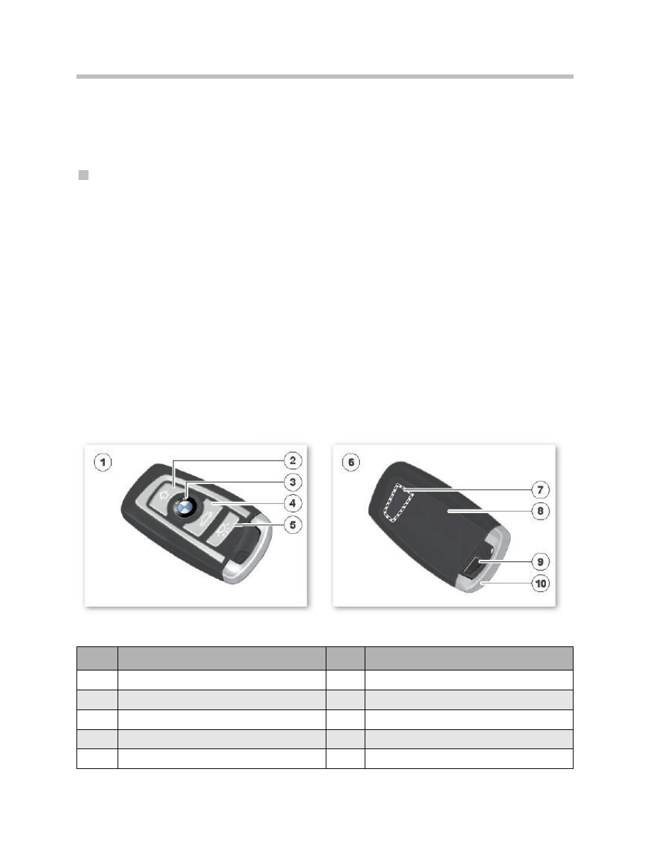
Index
Explanation
Index
Explanation
1
ID transmitter top view
6
ID transmitter rear view
2
Unlock/comfort open
7
Transponder coil area
3
Lock/comfort close
8
Battery compartment
4
Button for OPEN trunk
9
Button for mechanical key
5
Button for vehicle search function
10
Mechanical key
F01/F02 ID transmitter

The ID transmitter has a 512 MB data memory. The following data can be stored in the
ID transmitter:
Note: The remote control receiver is integrated in the antenna diversity facility
and passes the remote control signal to the Car Access System 4 via the
LIN bus.
Driver’s-door lock barrel
The lock barrel is connected mechanically via a linkage to the door lock. Hall sensors for
the lock barrel are integrated in the door lock.
The footwell module evaluates the signals from the Hall sensors for locking/unlocking
purposes.
Trunk locking barrel
The lock barrel is connected mechanically via a Bowden cable to the trunk lock. Turning
the spare key in the lock barrel opens the trunk lock.
Note: If the vehicle is fitted with an anti-theft alarm system, this causes an
alarm to be triggered. 1 Center lock button 2 Center lock button
22
F01 Central Locking System
Data
Explanation
km reading (mileage)
Current km reading of vehicle
VIN
Key number
Number of the ID transmitter
Fault code memory
entries
Which displays fault code memory entries and associates them with possible PuMAs
NAVI-DVD version
Data status of navigation DVD
Engine oil
Information on topping up or draining the engine oil, e.g. in the case of overfilling
Battery condition
Battery charge status
Integration stages
Integration stage that left the factory, integration stage last programmed
or currently available integration stage.
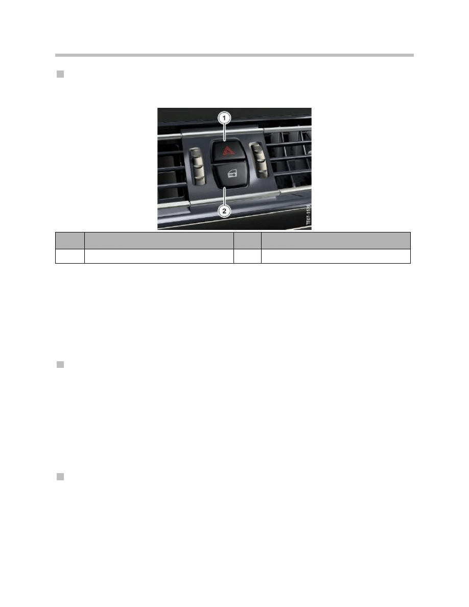
Center-lock button
The center-lock button is installed between the center of the outlets in the dashboard.
The center-lock button forms one unit together with the hazard warning lights button.
Note: The center lock button can also be operated when the vehicle is locked.
However, opening the vehicle door will trigger an alarm from the anti-
theft alarm system.
Central Locking Drive Units
A central locking drive unit consists of an electric drive unit and the unlocking/locking
mechanism.
Central locking drive units in the doors
The central locking drive units in the doors are equipped with two motors to facilitate the
unlocking/locking and central arrest functions of the vehicle.
Central arrest means that the locking button in the doors is separated mechanically from
the central locking drive unit.
As a result, the vehicle cannot be opened by pulling the locking button.
The Hall sensor for the door contact is additionally integrated in the central locking drive
unit.
Trunk central locking drive (trunk lock)
The central locking drive for the trunk is equipped with a motor for unlocking.
The central locking drive contains two microswitches which are actuated by the locking
pawl. If the locking pawl is in the pre-locking position, the status of the microswitch
changes from a high signal to a low signal. The electronics in the automatic soft-close
drive register the status and activate the drive. As soon as the locking pawl engages in
the main locking position, the drive stops.
23
F01 Central Locking System
F01/F02 button unit
Index
Explanation
Index
Explanation
1
Hazard warning flasher button
2
Central locking button

Note: The junction box electronics module evaluates the status of the
microswitch. The junction box electronics module sends the status via
the K-CAN2. This applies to vehicles with automatic trunk actuation.
The trunk lift requires this information so that it can start at the right
time, and not cause damage to the trunk lock.
The second microswitch is used to switch on the luggage compartment lighting. The
change in the status of the microswitch which occurs when the trunk is opened or closed
is also used to monitor the trunk for the purposes of the anti-theft alarm system.
Automatic soft-close drive for the trunk
The automatic soft-close drive is connected to the trunk lock with a Bowden cable. This
has the benefit that the drive can be fitted regardless of the available installation space.
The drive is connected to terminal 30B. The fuse is located in the rear power distribution
box. An electronics module is integrated into the automatic soft-close drive which is used
to monitor its proper functioning.
Closing the trunk places the rotary striker in the trunk lock in the pre-locking position. To
this end, a microswitch is located in the trunk lock which changes status when the lock is
actuated.
The electronics module in the automatic soft-close drive evaluates this change in status
and triggers the drive to switch on. The automatic soft-close drive is actuated until the
rotary striker is located in the main locking position. Once this has occurred, the
microswitch changes status again and the drive is switched off.
Note: The drive and the trunk lock can be replaced individually.
Fuel filler flap central locking drive
The central locking drive is equipped with a motor for unlocking/locking.
Manually releasing the fuel filler flap
The fuel filler flap can be released manually in the event of an electrical defect. The
release mechanism is located in the luggage compartment, on the right-hand side.
24
F01 Central Locking System
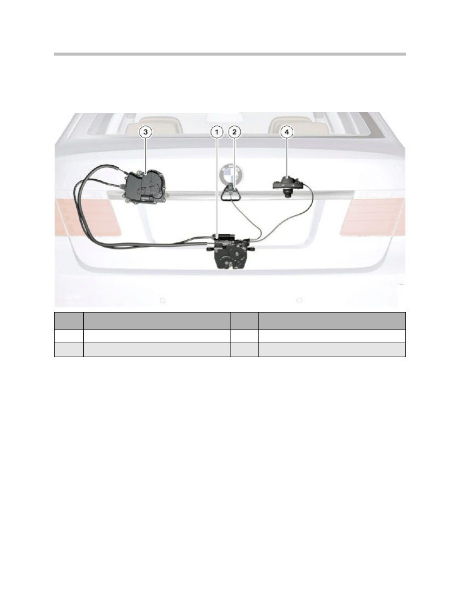
Manually Unlocking the Ttrunk
The US variant of the F01/F02 has an emergency trunk release mechanism. This makes
it possible to open the trunk manually from inside the luggage compartment.
Pulling on the handle (item no. 2) unlocks the trunk lock. The pulling motion on the han-
dle is transferred to the trunk lock by a Bowden cable, causing the trunk lock to unlock.
25
F01 Central Locking System
Index
Explanation
Index
Explanation
1
Trunk lock
3
Automatic soft-close drive
2
Handle for the emergency release
4
Trunk lock barrel mechanism
F01/F02 emergency trunk release mechanism
Document Outline
- Main Menu
- 01_F01 Introduction
- 02_F01 Powertrain
- 03_F01 Voltage Supply & Bus Systems
- 03.1_F01 Bus Systems
- 03.2_F01 Voltage Supply
- 03.3_F01 Energy Management
- 03.4_F01 Car Access System 4
- 04_F01 Chassis Dynamics
- 04.1_F01 Chassis and Suspension
- 04.2_F01 Dynamic Driving Systems
- 04.3_F01 Longitudinal Dynamics Systems
- 04.4_F01 Lateral Dynamics Systems
- 04.5_F01 Vertical Dynamics Systems
- 04.6_F01 Cruise Control Systems
- 05_F01 General Vehicle Electronics
- 05.1_F01 Comfort Access
- 05.2_F01 Central Locking System
- 05.3_F01 Automatic Soft Close
- 05.4_F01 Power Windows
- 05.5_F01 Sliding Tilting Sunroof
- 05.6_F01 Anti-theft System
- 05.7_F01 Automatic Luggage Compartment Lid
- 05.8_F01 Exterior Lighting
- 05.9_F01 Interior Lighting
- 05.10_F01 Wiper-Washer System
- 05.11_F01 Exterior Rear View Mirrors
- 05.12_F01 Seats
- 05.13_F01 Steering Column Switch Cluster
- 06_F01 Driver Information Systems
- 06.1_F01 Displays Indicators and Controls
- 06.2_F01 Head-up Display
- 06.3_F01 BMW Night Vision 2
- 06.4_F01 Active Blind Spot Detection System
- 06.5_F01 KAFAS
- 06.6_F01 PDC-TRSVC
- 07_F01 Information and Communication Technology
- 07.1_F01 Rear Seat Entertainment Systems
- 07.2_F01 Telephone System
- 07.3_F01 Voice Activation System
- 07.4_F01 Audio Systems
- 08_F01 Climate Control
- 09_F01 Passive Safety Systems
- 10_F01 Service Information
- 10.1_F01 System Functions
- 10.2_ISTA-Programming
Wyszukiwarka
Podobne podstrony:
05 6 F01 Anti theft System
Central locking system with interior lights AUTODATA
05 10 F01 Wiper Washer System
05 obslugiwanie statkow powietrznych systemy i organizacja obslug technicznych statkow powietrznych
b5 central locking
plants and the central nervous system pharm biochem behav 75 (2003) 501 512
IVa Rola banku centralnego w polskim systemie bankowym
05 jednostka centralna
05 DEFINICJA, Zarządzanie UWM, Systemy bankowe
Day 1 L6 Central nervous system
05 jednostka centralnaid 5712
05 obslugiwanie statkow powietrznych systemy i organizacja obslug technicznych statkow powietrznych
05 E65 Car Access System
04 6 F01 Cruise Control Systems
05 4 F01 Power Windows
09 F01 Passive Safety Systems
05 1 F01 Comfort Access
04 3 F01 Longitudinal Dynamics Systems
więcej podobnych podstron