
XXVI
Konferencja
Naukowo-Techniczna
awarie budowlane 2013
H
IROYUKI
S
UZUKI
, suzukihi@ar.meisei-u.ac.jp
Meisei University, Tokyo, Japan
K
AZUHIRO
N
AKAJIMA
, k-nakajima@lobtex.net
Lobtex Fastening System.co.,Ltd., Tokyo, Japan
EXPERIMENTAL STUDY ON CHARACTERISTICS
OF HIGH STRENGTH BLIND BOLTED JOINTS
BADANIA DOŚWIADCZALNE CECH POŁĄCZEŃ WYKONANYCH
ZE ŚRUB JEDNOSTRONNYCH WYSOKIEJ WYTRZYMAŁOŚCI
Abstract High strength blind bolts, which enable construction only from one side, are effective
for repairing or strengthening closed-section members in existing structures or for connecting box steel
pipes in new structures. In this study, experiments are conducted to verify the fatigue strength and other
basic characteristics of high strength blind bolted friction joints. As a result, it is revealed that
characteristics of high strength blind bolted friction joints are not less than those of joints using conven-
tional high strength bolts.
Streszczenie Śruby jednostronne wysokiej wytrzymałości stosowane są w konstrukcjach, do których
możliwy jest dostęp tylko z jednej strony. Są one efektywne w przypadku napraw lub wzmacniania prze-
krojów zamkniętych w istniejących konstrukcjach lub w przypadku mocowania stalowych rur prostokąt-
nych w konstrukcjach nowych. W niniejszej pracy przedstawiono wyniki eksperymentów przeprowa-
dzonych w celu zweryfikowania wytrzymałości zmęczeniowej oraz innych podstawowych charaktery-
styk połączeń ciernych wykonanych za pomocą śrub jednostronnych. Ustalono, że charakterystyki połą-
czeń ciernych wykonanych za pomocą śrub jednostronnych są nie gorsze niż charakterystyki połączeń
konwencjonalnych wykorzystujących śruby wysokiej wytrzymałości.
1. Introduction
High strength blind bolts, which enable construction only from one side, are effective for
repairing or strengthening closed-section members in existing structures or for connecting box
steel pipes in new structures. They enable the connection of members requiring no field
welding and therefore improve confidence in quality of connection, facilitate construction,
ensure safety and reduce the period of construction. In Japan, an increasing number of steel
highway bridges have recently been repaired or strengthened with the increase of traffic
volume and vehicle size, deterioration of bridges and requirements for greater seismic
resistance [1], [2]. Blind bolts are frequently used also in seismic retrofit of architectural
structures as a connection method requiring no field welding because neither curing and
ultrasonic testing involved in field welding nor welder qualifications are required. As for the
basic performance of blind bolts used for friction joints and for the structural characteristics of
connections, verifications have been made when the bolts were applied to architectural
structures or steel highway bridges [3]-[5] and their effectiveness have been identified. In the
former design of steel highway bridges in Japan, considering the effects of fatigue were
determined unnecessary unless the steel deck plate or highway bridge also carries street
508
Suzuki H. i in.: Experimental study on characteristics of high strength blind bolted joints
railway. The occurrence of fatigue cracks, however, reported at numerous positions of steel
highway bridges [6] and the increase in fatigue damage was of concern. Then, the “Fatigue
Design Guidance for Steel Highway Bridges”[7] was published in 2002, which made the
adoption of fatigue design mandatory also on steel highway bridges. No fatigue strength has,
however, been verified for blind bolted friction joints in the Guidance[7].
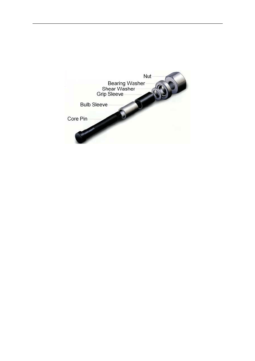
Figure 1 Components of high strength blind bolt
In this study, experiments are conducted to verify the slip coefficient, relaxation of axial
force of blind bolts and fatigue strength, which represent the basic characteristics of blind
bolted friction joints.
2. Outline of High Strength Blind Bolt
2.1 Characteristics of blind bolt
The components of a blind bolt are shown in Figure 1. Six parts constitute a blind bolt:
bulb sleeve that forms the bolt head behind the member, shear washer and grip sleeve that
support the bulb sleeve, bearing washer that secures the grip range, core pin with a special
trapezoidal screw and nut.
Blind bolts are used in all kinds of steel structures for repairing bridges. Members can be
fastened from one side using a dedicated electric shear wrench regardless of the field
environment or human skill. Strength equivalent to F8T can be secured by high strength bolt
for friction joint.
2.2 Fastening mechanism
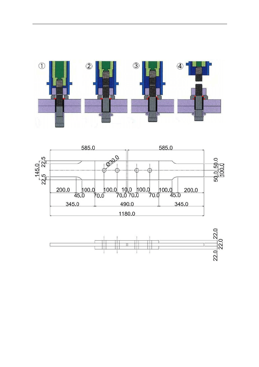
The process of fastening a blind bolt is outlined in Figure 2. The steps of fastening are
described below.
1) A blind bolt is inserted into the bolt hole and fastening is started using a special shear
wrench.
2) The bulb sleeve is deformed behind the member, forming a bulge (bolt head).
3) The shear washer is sheared by the axial force and the introduction of axial force to the
core pin is started.
4) The tail of the core pin is fractured, and thereby designated axial force is introduced.
Then, fastening is completed.
The axial force required for deforming the bulb sleeve is temporarily released due to the
shearing of the shear washer at the same time as a bulge is formed. Then, the designated axial
Konstrukcje stalowe
509
force is introduced to the core pin due to the fracture of the pin tail as for a torque-shear high-
strength bolt. Thus, axial force is introduced at two stages in the fastening mechanism for blind
bolts.
Figure 2 Outline of fastening of high-strength blind bolt
Figure 3 Specimen configuration
3. Slip Tests
3.1 Test procedure
Specimens is shown in Figure 3. Material of specimen is SN490B. The friction surface was
subjected to either shot blasting or grid blasting to set surface roughness at 50
µ
m Rz or higher.
Slip tests were conducted also for specimens of conventional high-strength bolted joints (M22,
S10T) for comparison with blind bolted joints. The load under which clear slip sound was created
was defined to be the main slip load. Three specimens per one type were tested.
510
Suzuki H. i in.: Experimental study on characteristics of high strength blind bolted joints
3.2 Test results
Tables 1 through 3 show the results of slip tests. The slip coefficient for blind bolted joints
(average of three specimens) is 0.62 for joints subjected to grid blasting and 0.57 for those
subjected to shot blasting. The slip coefficient for conventional high-strength bolted joints is
0.60 (average of three specimens). All exceeds slip coefficient of 0.40 in Specifications for
Highway Bridges in Japan.
Table 1 High strength blind bolt (grid blasting)
Specimen No-1
Specimen No-2
Specimen No-3
Slip Load (kN)
710
759
707
µ
0.610
0.652
0.607
Table 2 High strength blind bolt (shot blasting)
Specimen No-1
Specimen No-2
Specimen No-3
Slip Load (kN)
682
622
698
µ
0.586
0.534
0.600
Table 3 High strength bolt (shot blasting)
Specimen No-1
Specimen No-2
Specimen No-3
Slip Load (kN)
575
550
531
µ
0.625
0.598
0.577
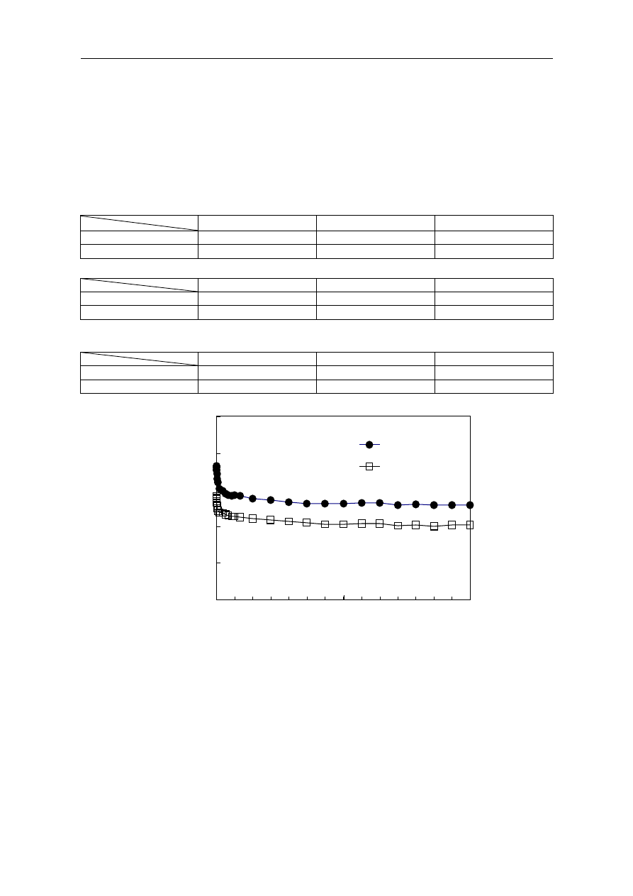
Figure 4 Relaxation of axial force
4. Relaxation Tests of Axial Force
For obtaining the axial force of the blind bolts in the relaxation tests, the special strain
gauge embedded in the core pin. The axial force was measured until 14 days passed.
The axial force of blind bolts and the time elapsed are shown in Figure 4. The bolt axial
force drops drastically in about one day after the bolt was fastened, and is gradually reduced
thereafter. After the elapse of about one week, the axial force becomes stable at a certain level.
At a point when 14 days passed, the reduction of axial force is about 4.5% of that at the time
170
180
190
200
210
220
0
7
14
Time (days)
M1-CH1
M1-CH2
A
x
ia
l
F
o
rc
e
(
k
N
)
Konstrukcje stalowe
511
of fastening. The results show that the relaxation of axial force of blind bolts is similar to the
results of relaxation test for conventional high-strength bolts [8] and that no special
consideration is required for the design axial force or the axial force to be introduced.
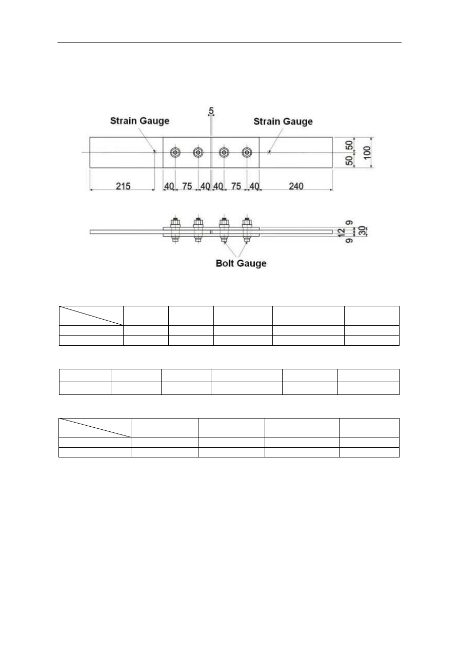
Figure 5 Specimen configuration
Table 4 Mechanical properties of steel plates
Material
Thickness
(mm)
Yield Stress
(MPa)
Tensile Strength
(MPa)
Elongation
(%)
Splice Plate
SS400
9
311
442
29
Base Material
SM400A
12
333
458
30
Table 5 Materials of High Strength blind bolt
Core Pin
Nut
Washer
Shear Washer
Grip Sleeve
Bulb Sleeve
SCM440
SCM440
SCM430
SCM430
SCM430
AISI1018
Table 6 Mechanical properties of core pin
Proof Stress
(MPa)
Tensile Strength
(MPa)
Reduction of Area
(%)
Elongation
(%)
Standard Value
Min 1006
1118-1216
Min 40
Min 14
Measurement
1111
1195
54
16
5. Fatigue Test
5.1 Test procedure
Specimen configuration is shown in Figure 5. Three specimens (M1, M2 and M3) were
tested. The bolt-hole has a diameter of 26.0 mm. Shot blasting was applied on the friction
surface of base plate and splice plate. A strain gauge was installed 215 mm from the end of the
base plate, and the stress to be applied in the fatigue test was measured in static loading tests.
The stress range was set 190 MPa. A rate of cyclic loading was 6 Hz. Tests were repeated until
the fracture of the base material with the maximum number of cycles set at 10 million times.
The mechanical properties of steel plates are listed in table 4. The materials of blind bolts and
the mechanical properties of core pin are shown in tables 5 and 6, respectively.
512
Suzuki H. i in.: Experimental study on characteristics of high strength blind bolted joints
5.2 Fatigue test results
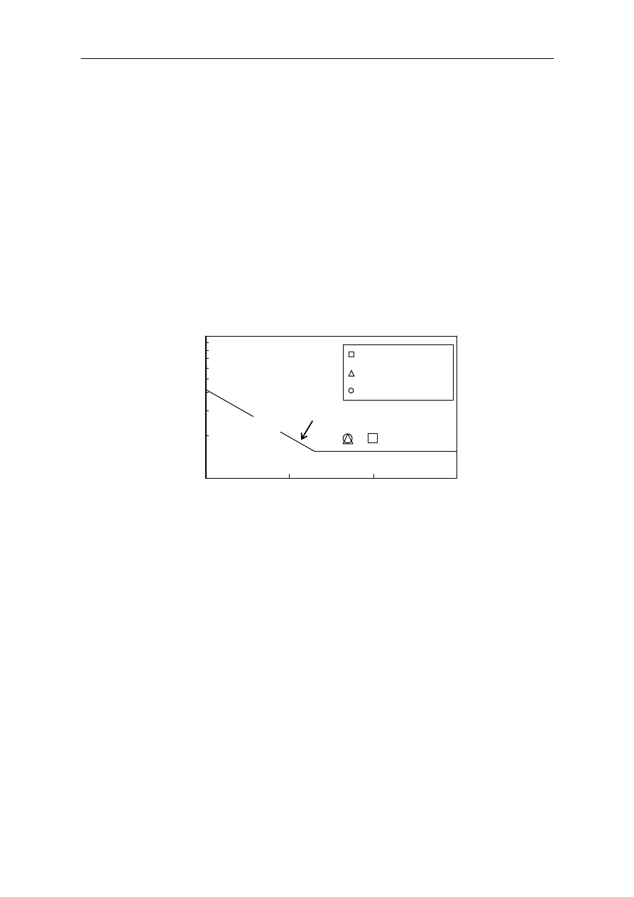
Figure 6 shows the results of fatigue test for blind bolted friction joints. The fatigue life of
average of three specimen is 6.65 million cycles. The “Fatigue Design Guidance for Steel
Highway Bridges”[7] specifies class B for the strength of conventional high-strength bolted
friction joints and basic fatigue strength of two million cycles is 155 MPa. The S-N curve of
strength class B is also shown in Figure 6. In the tests, however, stress grade was raised to
class A and the applied stress range was set 190 MPa. 190 MPa is basic fatigue strength of two
million cycles of the class A. In spite of having raised the applied stress range to 190 MPa,
number of cycles to fracture was 3.3 times of two million cycles which is a standard of the
number of cycles in basic fatigue strength. The number of cycles can be converted under
a certain condition using a formula specified in the “Fatigue Design Guidance for Steel
Highway Bridges” [7]. It becomes 1.8 times if the number of cycles of stress range of 190 MPa
is converted into the number of cycles of stress range of 155 MPa. That is, 6.65 million cycles
in 190 MPa turn into 12 million cycles in 155 MPa. The results reveal that fatigue strength of
blind bolted friction joints is not less than that of conventional high-strength bolted joints [7].
Figure 6. Fatigue test results
5.3 Fracture of specimen
In specimen M1, the base plate did not fracture until the number of cycles reached 10
million. Then, the test was discontinued. The base plate fractured from around the bolt-hole
along the width of the plate after approximately 4.95 million cycles in specimen M2 and after
approximately 5.00 million cycles in M3.
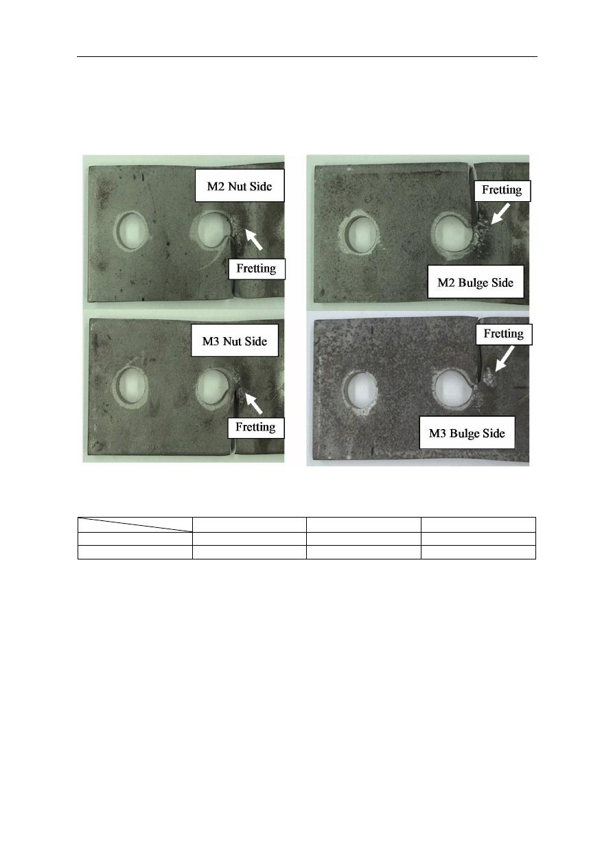
Photographs 1 and 2 show the fracture of the base plate on the bulge and nut sides after the
dismantling of M2 and M3. The fracture of the base plate progressed from the near end of the
bolt-hole. Fretting was observed on the surface due to cyclic loading. Fatigue-induced cracks
that occurred on the surface around the bolt-hole subjected to fretting may have caused the
base plate to fracture.
6. Tensile Tests
In order to verify the strength of the blind bolt after the fatigue test, specimens M2 and M3
were dismantled and tensile tests were conducted for bolts. The results of tensile tests for blind
bolts at the time of shipment and after the fatigue test are shown in table 7.
Stress Class B(155MPa) S-N Curve
100
1000
1.0E+5
1.0E+6
1.0E+7
1.0E+8
Number of Cycles N
S
tr
e
s
s
R
a
n
g
e
(
M
P
a
)
M1
:
10 million cycles
M2
:
4.95 million cycles
M3
:
5.00 million cycles
Strength Class B(155Mpa) S-N Curve
Konstrukcje stalowe
513
After the tensile test, blind bolts all fractured at the screw of the bolt. It is therefore evident
that the bulge (bolt head) that was deformed had sufficient strength. Tensile strength remained
unchanges after the fatigue test. It is verified that no strength reduction occurs in blind bolts
after cyclic loading was applied approximately five million times.
Photograph 1 Fracture of base material (Nut side) Photograph 2 Fracture of base material (Bulge side)
Table 7 Results of tensile test before and after fatigue test
Maximum (kN)
Minimum (kN)
Average (kN)
Before Fatigue (N = 10)
270.9
269.2
269.9
After Fatigue (N = 8)
270.8
269.2
270.0
7. Conclusions
Tests were conducted to verify the slip factor, relaxation of axial force and fatigue strength,
which represent the basic characteristics of high-strength blind bolted friction joints. Tensile
strength after fatigue test was also verified. The findings are described below.
1)
Slip tests were conducted for friction surface that was subjected either to shot blasting or
grit blasting. As a result, a slip factor of 0.45 or higher was obtained. Performance similar
to that of conventional high-strength bolted friction joints can be obtained by properly
blasting the friction surface.
2)
Relaxation of axial force was approximately 5% after 14 days. The relaxation of axial force
of blind bolts is similar to that of conventional high-strength bolts. No special consideration
is required for the design axial force or the axial force to be introduced.
3)
Fatigue strength of blind bolted friction joints was similar to that of conventional high-
strength bolted joints.

514
Suzuki H. i in.: Experimental study on characteristics of high strength blind bolted joints
4)
It was verified in tensile tests before and after fatigue testing that no strength reduction
occurred in blind bolts after cyclic loading was applied approximately five million times.
Acknowledgment
This bolt are a patent of Huck International, lnc in USA. In addition, Fuserashi co., LTD
produces it in Japan. The authors would like to express their gratitude to the staff concerned
of Fuserashi Co., Ltd. for providing high-strength blind bolts and supporting in tensile tests.
References
1.
Yoshizu, H. and Fujii, K.: Design for reinforcing steel deck Langer bridges, Civil
Engineering, Vol. 59 No. 7, pp 55-62, July 2004 (in Japanese).
2.
Hashimoto, Y, Kameyama, S. and Hiromura, O: Reinforcement of splice at steel deck
U-shaped rib butt welding, Takigami Technical Report, Vol. 23, pp. 87-96, November
2005 (in Japanese).
3.
Ohno, T., Natori, T. and Matsumoto, Y.: Friction bonding method using torque control
type one-side construction high-strength bolts, Yokogawa Bridge Group technical report,
No. 26, pp. 236-240, January 1997 (in Japanese).
4.
Matsumura, M., Kitada, T., Yoshizu, H., Kijitani, M. and Muramoto, K.: An experimental
study on corner reinforcement for rectangular steel columns using one-side bolts,
Proceedings of 9th symposium on the seismic design of bridges and other structures based
on the seismic strength method, pp. 207-212, February 2006 (in Japanese).
5.
Tanaka, T., Tabuchi, M., Furumi, K., Murayama, M. and Matsubara, Y.: A study on the
connection between a box steel pipe column with increased thickness and a beam,
Proceedings of annual conference on steel structures, Vol. 3, pp. 355-362, November 1995
(in Japanese).
6.
Takada, Y., Hirano, T. and Sakano, M.: Report on fatigue-induced damage to steel slabs
on the Hanshin Expressway, Proceedings of the 61st Annual Conference of Japan Society
of Civil Engineers, pp. 1067-1068, September 2006 (in Japanese).
7.
Japan Road Association: Fatigue Design Guidance for Steel Highway Bridges, March 2002
(in Japanese).
8.
Japan Society of Civil Engineers: Steel structure series 15 Design, construction and
maintenance guidelines for high-strength bolted friction joints (draft), December 2006
(in Japanese).
Wyszukiwarka
Podobne podstrony:
Experimental study on drying of chilli in a combined Microwave vacuum rotary drum dryer (Weerachai K
Interruption of the blood supply of femoral head an experimental study on the pathogenesis of Legg C
An experimental study on the development of a b type Stirling engine
Interruption of the blood supply of femoral head an experimental study on the pathogenesis of Legg C
An experimental study on the drying kinetics of quince
Experimental investigation on micromilling of oxygen free, high conductivity copper using tungste
Experimental Study On Stirling Engine Generator And Solar Receiver System For Future Space Applicati
Pancharatnam A Study on the Computer Aided Acoustic Analysis of an Auditorium (CATT)
Monitoring the Risk of High Frequency Returns on Foreign Exchange
Comparison of theoretical and experimental free vibrations of high industrial chimney interacting
Pancharatnam A Study on the Computer Aided Acoustic Analysis of an Auditorium (CATT)
Experimental study of drying kinetics by forced convection of aromatic plants
Ebsco Bialosky Manipulation of pain catastrophizing An experimental study of healthy participants
Comparison of theoretical and experimental free vibrations of high industrial chimney interacting
NASA CR 180678 Calculation of Aerodynamic Characteristics at High Angles of Attack for Airplane Conf
Ebsco Bialosky Manipulation of pain catastrophizing An experimental study of healthy participants
Microwave drying characteristics of potato and the effect of different microwave powers on the dried
A comparative study on conventional and orbital drilling of woven carbon
więcej podobnych podstron