1
LQG Multiple Model Control of a Variable Speed Pitch Regulated Wind
Turbine
F. Lescher, J.Y. Zhao, A. Martinez
ERPA-EIGSI
26 rue Vaux Le Foletier, 17041 La Rochelle, France.
E-mail: fabien.lescher@eigsi.fr
Abstract - This paper deals with the control of variable speed,
pitch regulated wind turbine in the whole plant operating
area. Wind turbine operating area can be divided into several
zones, depending on wind speed, and control objectives are
different for each operating zone. A control structure based
on a multiple linear model Takagi Sugeno approach is pre-
sented to take into account system non linearities and evolu-
tions of contol objectives. Optimal LQG control synthesis is
used to design linear controller for each linearized model in
response to the multivariable and multiobjective control prob-
lem.
Keywords—Wind energy, multiple model, LQG synthesis.
I. INTRODUCTION
Wind energy is nowadays considered as the most viable re-
newable energy option, but wind energy cost is still higher
than traditional energy options. Consequently, wind en-
ergy plant life has to be increased, and produced energy
yield has to be optimized. The wind turbine control algo-
rithms have an important influence on these requirements
[BUR 01], [LEI 00a]. The two main objectives of the wind
turbine control system are the optimization of produced en-
ergy and the alleviation of dynamic loads experienced by
the mechanical structure of the wind power plant.
Wind energy conversion systems present three different op-
erating modes depending on wind speed acting on turbine
rotor: for low wind speeds, main conversion objective con-
sists on maximizing energy extracted from wind, whereas
for higher wind speeds, produced electric power has to be
regulated to generator nominal power. To achieve these re-
quirements, wind turbine control system acts on generator
electromagnetic torque and on blades pitch angle, by con-
trolling electric or hydraulic actuators located on the roots
of blades.
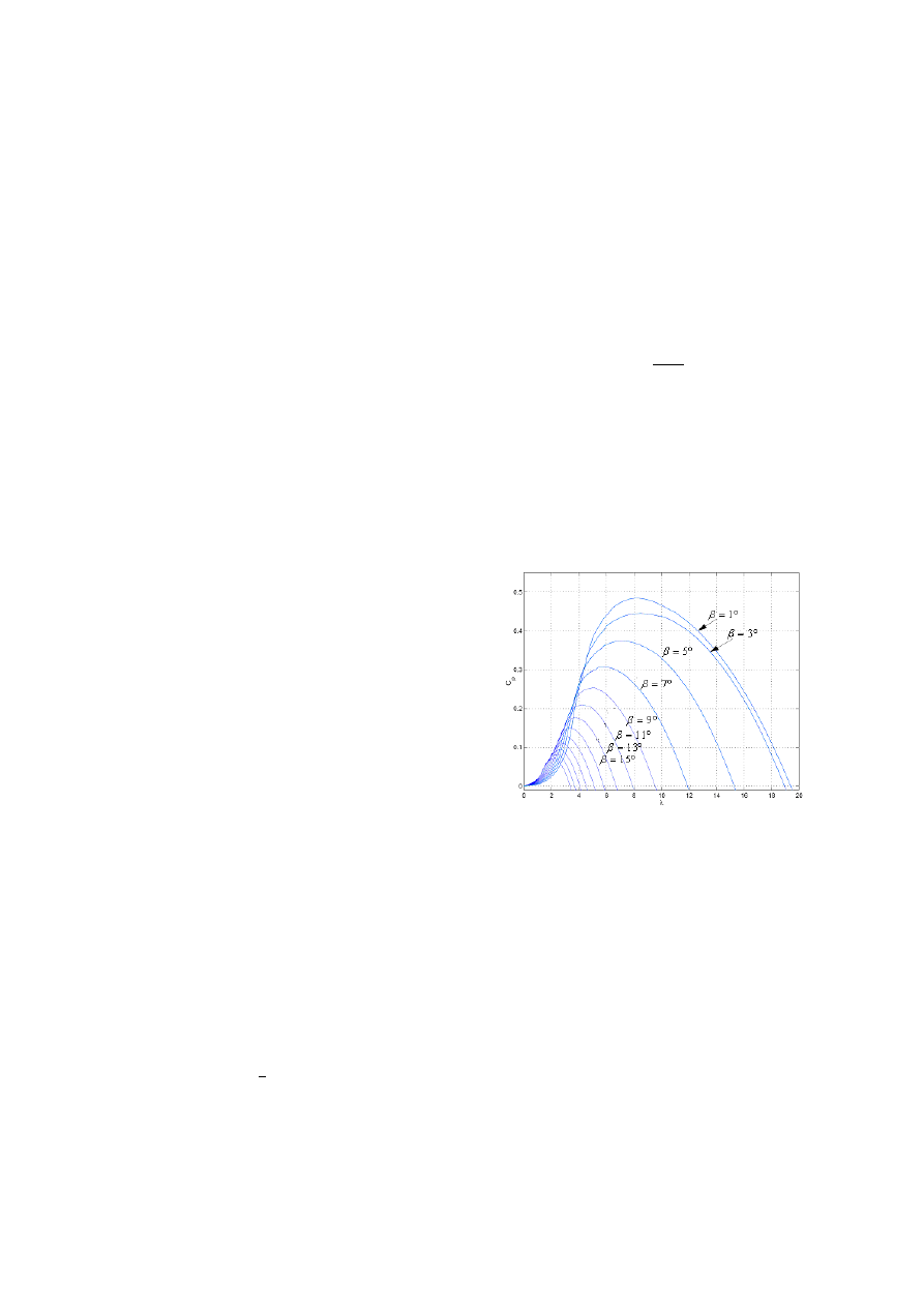
Aerodynamic power P
aero
extracted from wind by the tur-
bine is function of air mass density ρ, of wind velocity v
and of power coefficient C
p
:
P
aero
=
1
2
ρπR
2
v
3
C
p
(1)
with R the wind rotor radius. Power coefficient C
p
is a non
linear function (Figure 1) depending on blades pitch angle
β and on tip speed ratio λ defined by the relation:
λ =
ω
T
R
v
(2)
with ω
T
the rotational speed of the turbine. Wind turbine
control system has then to adjust turbine rotational speed
and blades pitch angle to wind speed acting on blades.
Wind velocity is a stochastic quantity which can vary very
quickly and which is unmeasurable because it represents
the averaged wind velocity on wind field passing through
turbine rotor. The best way to know this quantity is then to
estimate it from turbine behavior [LEI 00b]. Wind turbine
Fig. 1. Power coefficient C
p
(λ, β) curves.
control problem is thus a multiobjective control problem
of a multivariable and non linear system depending on a
stochastic and unmeasurable parameter, the wind speed. In
response to this problem, several controller synthesis meth-
ods have been used, as fixed or scheduled PID controllers
[CAR 96], [HAN 02] or fuzzy logic controllers [VIH 02].
Main drawback of these methods is that they do not pro-
vide guarantees of an optimal behavior of the system for
a criterion depending on the different control objectives.
Optimal control [EKE 97][MUN 05] or robust control syn-
thesis minimizing a H
∞
criterion [BON 94][BIA 04] have
been employed from a linearized model of the turbine and
for one operating zone.
In this paper, a control system structure optimizing a se-
lected trade off for the whole operating area between en-
ergy conversion maximization and reduction of mechani-
cal loads experienced by turbine drive train is presented.
The controller synthesis is based on a Takagi-Sugeno mul-
tiple linear model representation of the non linear system.
Hence, for each linearized model on the system reference
trajectory, a multivariable LQG controller, minimizing a
quadratic criterion depending on the different control ob-
jectives and taking into account the stochastic properties of
the wind speed, is designed. Control applied to the global
system is then obtained by an interpolation of the controls
calculated by the different controllers.
The paper is organized as follows: wind turbine model and
control task are firstly described. Then multiple model rep-
resentation of the system and controller synthesis are pre-
sented. Controller performances are finally compared with
those of a classic controller at the sight of simulation re-
sults.
II. W
IND
T
URBINE
M
ODELLING
Figure 2 presents the wind conversion system structure.
Modelling of each component of the system is then real-
ized. Wind velocity in a fixed point of space has known
Fig. 2. Wind energy conversion system structure.
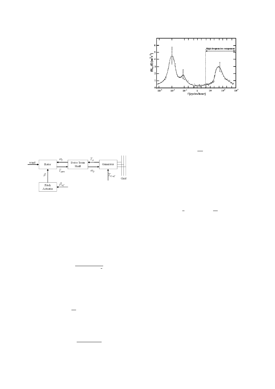
properties in the frequency range, represented by Van der
Hoven spectrum (Figure 3). Two main components appear
in this spectrum: a slow time varying component, repre-
senting mean value v
m
(t) of wind speed, and a turbulent
one v
t
(t). Properties of this high frequency part can be
used by wind turbine control system. A model of the power
spectrum of the turbulent part is proposed by von Karman
[NIC 02][EKE 97]:
Φ
v
(ω) =
K
(1 + (T
v
ω)
2
)
5
6
(3)
For control synthesis purpose, a linear model of turbulent
part v
t
(t) is employed, composed by a first order filter dis-
turbed by a Gaussian white noise m
v
(t) [EKE 97]:
˙
v
t
= −
1
T
v
v
t
(t) + m
v
(t)
(4)
Power spectrum corresponding to this linear model is:
Φ
v
(ω) =
K
(1 + (T
v
ω)
2
)
(5)
Fig. 3. Spectrum of horizontal wind speed
and represents an acceptable approximation of (3). Time
constant T
v
of (4) and standard deviation of m
v
(t) are de-
pending on mean wind speed m
v
(t) and on plant installa-
tion site properties [NIC 02]:
T
v
=
L
v
m
σ
m
= k
σ,v
v
m
Wind action on turbine is described by equation (1). Ex-
tracted torque depends on tip speed ratio λ, which is func-
tion of turbine rotational speed ω
T
and of wind speed v,
and on blades pitch angle β:
T
aero
=
1
2
ρπR
5
C
p
(λ, β)
1
λ
3
ω
2
T
(6)
Power coefficient C
p
(λ, β) curves of the considered wind
turbine are represented on Figure 1, and are modelled by a
two variables polynomial:
C
p
(λ, β) =
X
i,j=1..4
a
ij
λ
i
β
j
(7)
flexibility of drive train connecting wind rotor to generator
is taken into account by the model: drive train structural
dynamics may give rise to oscillating phenomena on drive
train torque at a resonance frequency that may induce an
increase of mechanical loads [PET 02][BUR 01]. To repre-
sent this phenomenon, flexible drive train is described by a
two inertia model connected by a spring and a damper (Fig-
ure 4). Drive train mechanical behavior is then described
by the equations:
J
T
˙ω
T
=
T
aero
− f
T
ω
T
− T
D
J
G
˙ω
G
=
T
D
− f
G
ω
G
− T
G
T
D
= d(ω
T
− ω
G
) + k(θ
T
− θ
G
)
(8)
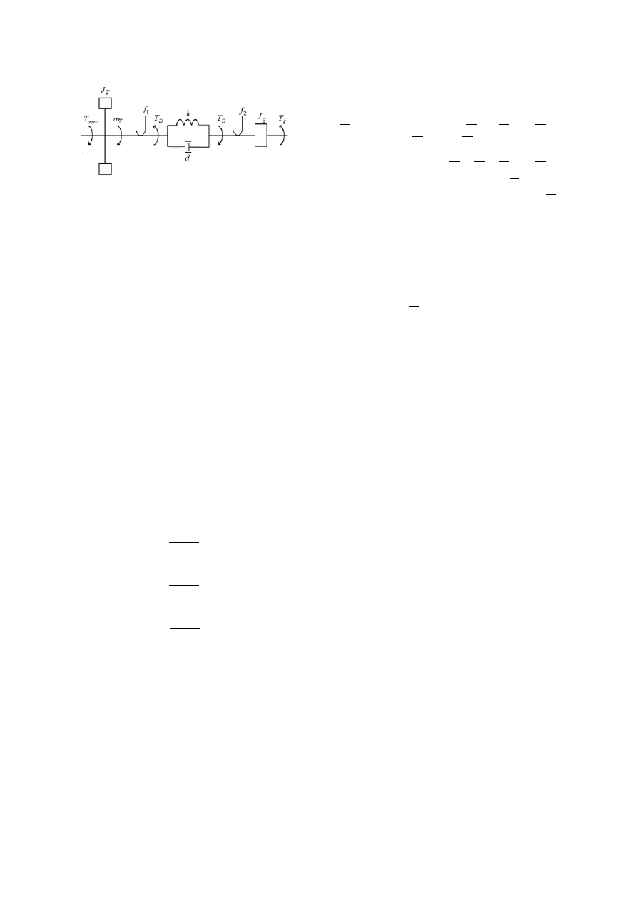
Fig. 4. Drive train two mass model
System electrical part, corresponding to generator and
power electronic components, has very fast dynamics com-
pared with mechanical part, and consequently, and consid-
ering the objectives of the study, electrical dynamics are
neglected. Hence, electromagnetic torque T
G
is supposed
equal to its reference T
G,ref
.
Pitch actuator represents the hydraulic or electric system
which makes the blades revolve around lengthwise axis.
This system is described by a first order transfer function
with saturation on pitch angle β and on pitch rate ˙
β.
The interconnexion between the different subsystems leads
to a global highly non linear system, due to the expression
of extracted aerodynamic torque T
aero
. For controller syn-
thesis purpose, the global model can be linearized around
an operating point, linearizing the expression of aerody-
namic torque:
∆T
aero
= k
ω
∆ω
T
+ k
v
∆v + k
β
∆β
(9)
Operator ∆ corresponds to the deviation of values from lin-
earization point S
i
(x
i
, u
i
), and coefficients k
ω
, k
v
and k
β
are defined by:
γ
ω
i
=
µ
∂T
aero
∂ω
T
S
i
γ
v
i
=
µ
∂T
aero
∂v
S
i
(10)
γ
β
i
=
µ
∂T
aero
∂β
S
i
Linearized model can then be set on state space represen-
tation:
˙x = A
i
∆x + B∆u + Gw
(11)
State vectors are defined by:
x =
ω
T
ω
G
T
D
β
v
u =
µ
T
G
β
ref
w = m
v
(12)
and state matrice A
i
by:
1
J
T
(γ
ω
i
− f
T
)
0
−
1
J
T
1
J
T
γ
β
i
1
J
T
γ
v
i
0
1
J
G
f
G
1
J
G
0
0
d+
k
J
T
(γ
ω
i
− f
T
)
−d−
k
J
G
f
G
k
J
T
−
k
J
G
k
J
T
γ
β
i
k
J
T
γ
v
i
0
0
0
−
1
T
b
0
0
0
0
0
−
1
T
v
setting:
B =
0
0
−
1
J
G
0
k
J
G
0
0
1
T
b
0
0
G =
0
0
0
0
1
III. W
IND
T
URBINE
C
ONTROL
S
YNTHESIS
A. Control Task
Wind turbine operation area can be divided into three
zones, depending on wind speed acting on blades. Energy
conversion objectives, and thus control objectives, are dif-
ferent for each zone.
For low wind speed, i.e. for v < v
1
, main objective is to
maximize system energy conversion yield. In this Partial
Load 1 zone, system has to operate at C
p
(λ, β) = C
p,max
.
Pitch angle β is then maintained constant at β
opt
and ro-
tational speed ω
T
is controlled to operate at λ = λ
opt
, by
acting only on generator electromagnetic torque T
G
.
For higher wind speed, corresponding to v
1
< v < v
2
, at-
tained turbine rotational speed by applying previous control
strategie would be over nominal generator speed. In this
Partial Load 2 zone, turbine rotational speed ω
T
is main-
tained at the nominal generator speed by acting on electro-
magnetic torque T
G
. Pitch angle β is also maintained at
β
opt
to maximize energy conversion efficiency.
For high wind speed, i.e. v > v
2
, wind turbine operates
in Full Load and electric produced power has to be regu-
lated at nominal generator power. Turbine rotational speed
is maintained around nominal generator speed and pitch
angle β is controlled in order to reduce power coefficient
C
p
(λ, β). Control system is then multivariable in this zone,
because it acts on both generator torque and pitch angle.
Other constraints than those related to generator specifica-
tions explain power limitation, such as blades noise emis-
sion limitation or limitation of mechanical loads supported
by the mechanical structure [BOS 01][BUR 01].
Evolution of main values in function of wind speed are pre-
sented on Figure 5.
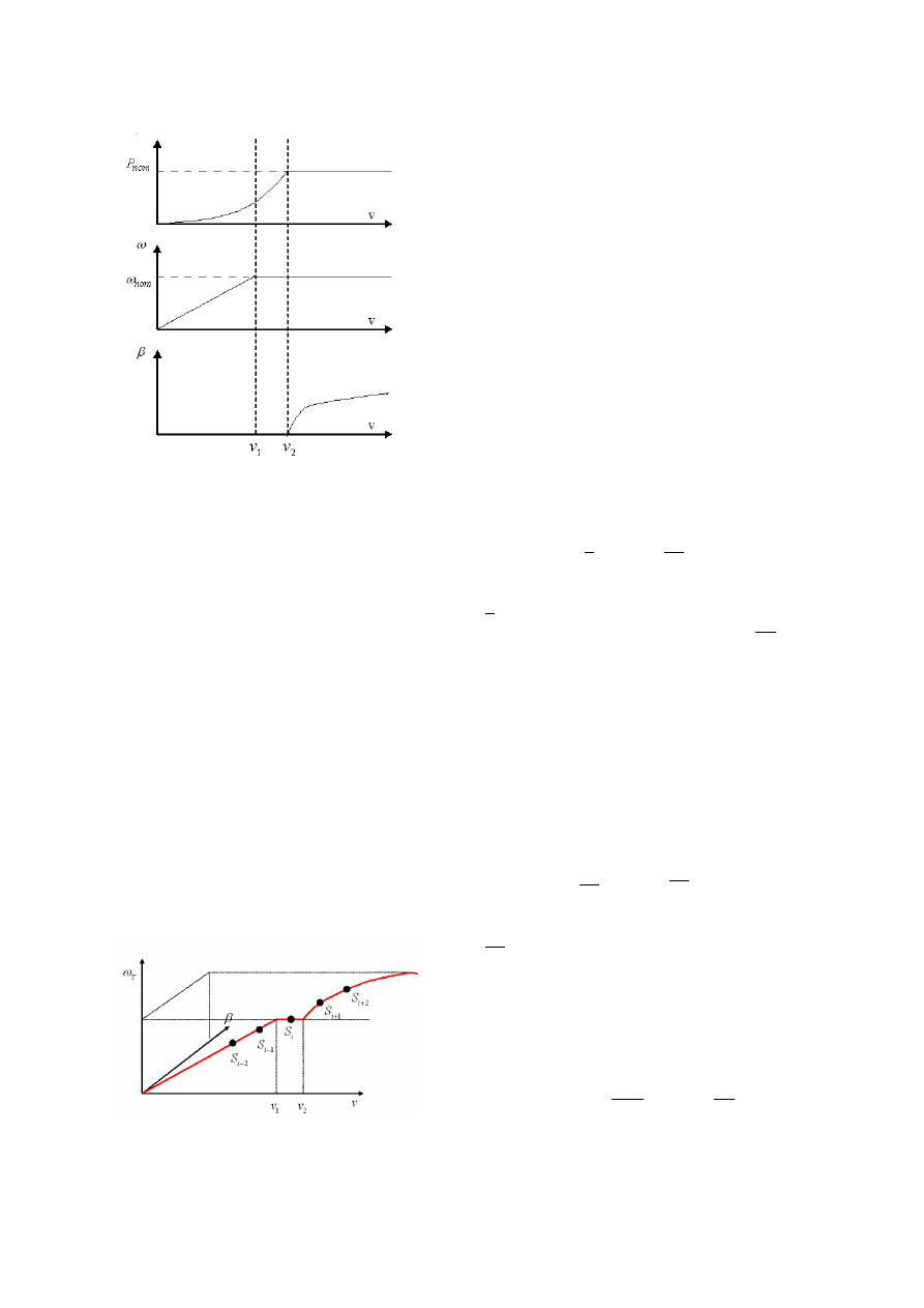
Fig. 5. Main temporal series evolution function of wind speed.
Main control objective is then to track these curves, in order
to guarantee a good energy conversion. Second objective is
the alleviation of mechanical fatigue experienced by flexi-
ble drive train. This objective is equivalent to reducing the
fluctuations of torsional drive train torque T
D
.
These two objectives are clearly contradictory: for exam-
ple, maximization of energy yield induces a sudden varia-
tion of turbine rotational speed in response to a wind gust,
and consequently a fast variation of generator torque T
G
,
and by the way, high loads on drive train. Wind turbine
control system has then to optimize a trade off between
these two objectives.
B. Multiple Model Approach
Because of both system non linearities and different operat-
ing zones, a multiple model approach is used for controller
synthesis. Global system behavior is described by multiple
linear models around several operating points S
i
(x
i
, u
i
)
setting on system optimal trajectory (Figure 6). For each
linearized model a linear controller is synthetized follow-
ing the rules of linear control.
Fig. 6. System reference trajectory.
C. LQG Optimal control
LQG optimal control is particularly well suited for wind
turbine controller synthesis.
Indeed, for a linear sys-
tem, LQG synthesis guarantees an optimal behavior for a
selected criteria depending on several control objectives.
Moreover, LQG synthesis takes into account stochastic
properties of the system disturbances, and thus in our case,
stochastic properties of turbulent part of wind speed.
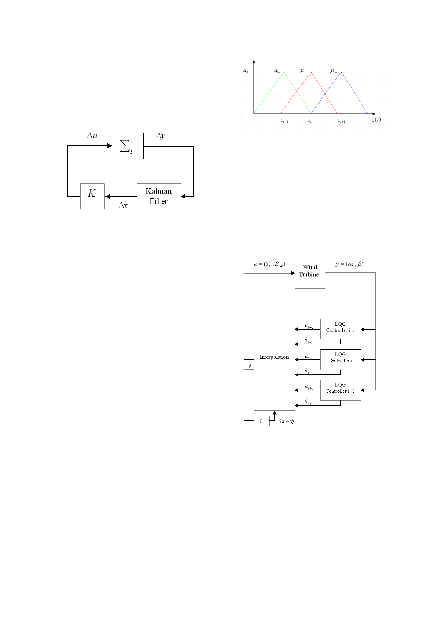
Thus, for each linearization point S
i
(x
i
, u
i
), a LQG con-
troller is synthetized, composed by a Kalman Filter, for
linear system state vector estimation ∆ˆ
x = ˆ
x − x
i
and
by a state feedback ∆u = K∆ˆ
x (Figure 7). Static state
feedback K is calculated in order to minimize a quadratic
function J depending on control objectives, which are de-
pendant on operating zone.
In Partial Load 1, system has to operate at λ = λ
opt
in or-
der to extract the maximum of energy. Quadratic function
J is defined by:
J =
Z
T
0
¡
q
1
∆λ(t)
2
+ q
2
∆T
D
(t)
2
+ r∆T
G
(t)
2
¢
dt
(13)
∆λ(t) corresponds to ∆λ(t) = λ(t) − λ
opt
multiplied by
a low pass filter W
λ
(s). In the same way, ∆T
D
(t) corre-
sponds to ∆T
D
(t) = T
D
(t) − T
D,i
multiplied by a high
pass filter W
T
D
(s). Indeed, tracking of λ = λ
opt
at high
frequency is not required because it would induce sudden
variations of turbine rotational speed and thus high me-
chanical loads on drive train. High pass filter W
T
D
permits
also to increase system damping for a high frequency range
which includes drive train resonance frequency.
In Partial Load 2, generator rotational speed has to be main-
tained at its nominal value. Quadratic function J becomes:
J =
Z
T
0
¡
q
1
∆ω
T
(t)
2
+ q
2
∆T
D
(t)
2
+ r∆T
G
(t)
2
¢
dt
(14)
∆ω
T
(t) corresponds to rotational speed variations filtered
by a low pass filter.
In Full Load, produced electric power has to be regulated
to its nominal value. Quadratic function is then expressed
by:
J =
Z
T
0
(q
1
∆P
elec
(t)
2
+ q
2
∆T
D
(t)
2
+ r
1
∆T
G
(t)
2
+ r
2
∆β
ref
(t)
2
)dt
(15)
One can then rewrite in each case quadratic function J as
the LQG synthesis classic form:
J =
Z
T
0
¡
x
T
Qx + u
T
Ru + 2x
T
Su
¢
dt
(16)
Fig. 7. LQG controller structure
D. Controller Interpolation
Global control applied to the non linear system is calcu-
lated from an interpolation of controls determined by the
controllers of the linearized models. A Takagi Sugeno ap-
proach is used: based on fuzzy logic interpolation, this
method guarantees smooth transitions between operating
regions. Thus, the non linear system is considered as a
weighted sum of linearized models:
˙x(t) =
N
X
i=1
µ
i
(z(t)) (A
i
(x(t) − x
i
) + B
i
(u(t) − u
i
))
z(t) is the system decision variable and weighting func-
tions µ
i
(z(t)) have the following properties:
µ
i
(z(t)) ≥ 0, i = 1..N
N
X
i=1
µ
i
(z(t)) = 1
Decision variable z(t) has to permit to controller to identify
the location of the operating point on the optimal trajectory.
As wind speed is a system state variable (12), wind speed
is estimated for each subsystem by corresponding Kalman
Filter. Global wind speed estimate ˆ
v(t) is determinate by
the interpolation of ˆ
v
i
(t) estimated by each Kalman Fil-
ter. Decision variable z(t) used for this interpolation to
calculate weighting functions µ
i
(z(t)) is the wind speed
estimate ˆ
v(t − τ ) with a time delay τ .
Used weighting functions µ
i
(z(t)) are represented on Fig-
ure (8).
Fig. 8. Weighting functions µ
i
(z)
Global control u applied to the system is then expressed by:
u(t) =
N
X
i=1
µ
i
(z(t))(u
i
+ K
i
(∆ ˆ
x
i
(t)))
(17)
Structure of the LQG multiple mode controller is presented
on Figure 9.
Fig. 9. Global controller structure
E. Controller Evaluation
Proposed control system is validated from numeric simu-
lations, comparing its performances with performances of
a classic PI controller in operating zones corresponding
to low wind speed (Partial Load 1) and high wind speed
(Full Load). Wind turbine model implanted in the Matlab-
Simulink package corresponds to a 1.2 MW variable speed
and pitch regulated wind energy conversion system.
In Partial Load 1, PI controller is calculated from a lin-
earized model of the system around an operating point,
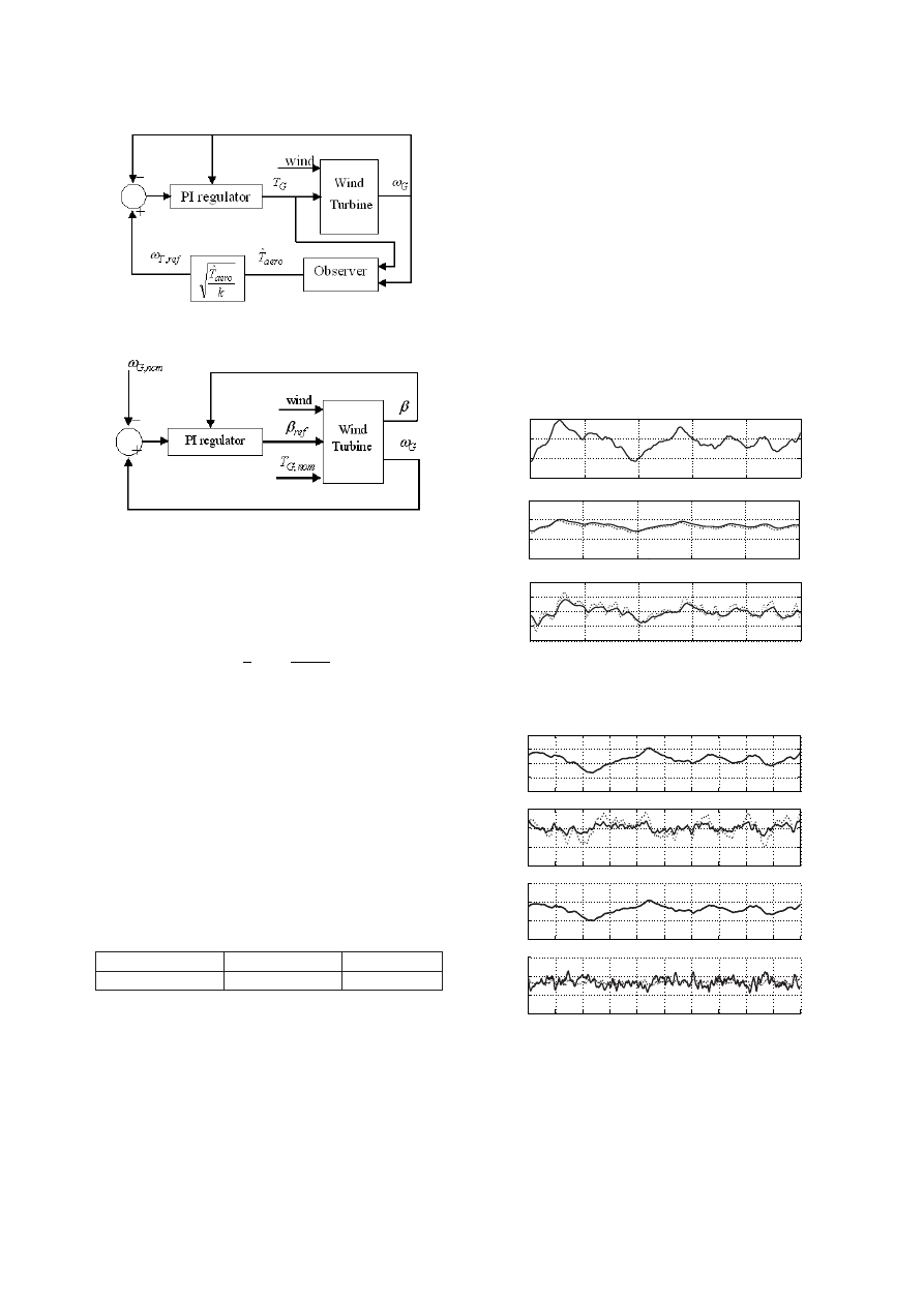
Fig. 10. Partial Load: PI controller Structure
Fig. 11. Full Load: PI controller structure.
taking into account than on the reference trajectory, the ex-
tracted aerodynamic torque is expressed as:
T
aero
=
1
2
ρπR
5
C
p,opt
λ
3
ω
2
T
(18)
Reference ω
T,ref
is calculated from an estimate of aerody-
namic torque ˆ
T
aero
, calculated by a Kalman Filter (Figure
10).
Loss of extracted energy relatively to maximal available en-
ergy, i.e. energy extracted by wind turbine operating dur-
ing all the simulation at C
p
= C
p,opt
are presented for the
two considered controller in Table III-E. Temporal series
of wind speed, rotational speed and drive train torsional
torque are presented on Figure 12. Energy yield is very
high for both controllers, and LQG controller better re-
duces drive train torque fluctuations.
Controller
LQG Controller
PI Controller
Energy efficiency
99.03 %
99.08 %
TABLE I
P
ARTIAL
L
OAD
O
PERATION
: E
NERGY EFFICIENCY
For Full Load operation, PI controller structure is presented
on Figure 11. This PI controller regulates generated elec-
tric power by correcting generator rotational speed acting
only on blades pitch angle β, the generator electromag-
netic torque being fixed to its nominal value T
G,nom
. This
controller is thus monovariable, unlike proposed LQG con-
troller. Temporal series of wind speed, generated electric
power, blades pitch angle and drive train torsional torque
are presented on Figure 13. Variations of electric power
around the nominal plant value (1.2 MW) are much more
reduced for the LQG controller. Fluctuations of drive train
torsional torque are in return higher for the LQG controller.
Netherveless, analyzing Power Spectral Density of drive
train torsional torque (Figure 14), one constates than fluc-
tuations which appear at the flexible shaft resonance fre-
quency, which are most damageable, are roughly the same
for the two considered controllers.
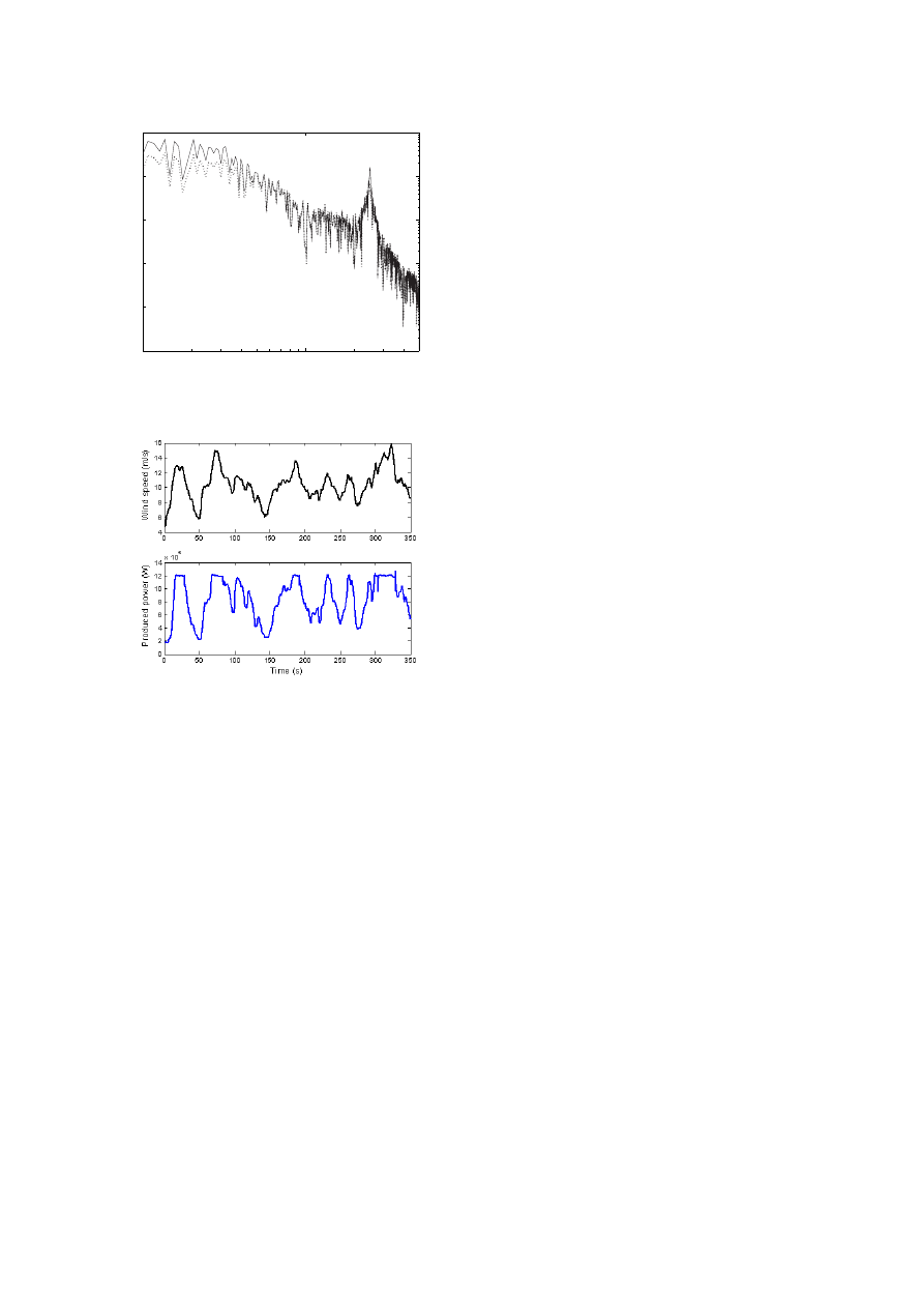
Simulations for a wind speed serie with large variations
show system behavior for transitions between different op-
erating regions (Figure 15).
0
50
100
150
200
250
4
5
6
7
Wind speed (m/s)
0
50
100
150
200
250
0
1
2
3
W
p
al (rad/s)
0
50
100
150
200
250
0
0.5
1
1.5
2
x 10
5
T
t
ors (Nm)
Time (sec)
Fig. 12.
Partial Load Operation, Temporal series: solid: LQG
controller, dot: PI controller.
0
20
40
60
80
100
120
140
160
180
200
12
14
16
18
20
Wind speed (m/s)
0
20
40
60
80
100
120
140
160
180
200
1.18
1.19
1.2
1.21
x 10
6
Electric Power (W)
0
20
40
60
80
100
120
140
160
180
200
5
10
15
20
Beta (°)
0
20
40
60
80
100
120
140
160
180
200
4.9
4.95
5
5.05
x 10
5
T
t
ors (N/m)
Time (sec)
Fig. 13. Full Load Operation, Temporal Series: solid: LQG con-
troller, dot: PI controller.
IV. C
ONCLUSION
In this paper, a variable speed wind turbine control struc-
ture is presented for the whole system operation range. The
0.1
1
5
10
−1
10
0
10
1
10
2
10
3
10
4
Torsional torque
T
t
ors
Frequency (Hz)
Fig. 14. Full Load Operation, Drive train torque Power Spectral
Density: solid: LQG controller, dot: PI controller.
Fig. 15. Proposed controller, whole operation range simulation
control system, based on a multiple model representation
of the system, takes into account the non linearities of the
system and the different control objectives depending on
operating zones. LQG control synthesis guarantees an opti-
mal behavior of the system for a selected trade off between
different control objectives and for each linear model. Pro-
posed controller evaluation shows better system behavior
for each operating zone than a classic controller, and good
transitions between the different operating zones.
REFERENCES
[BIA 04]
B
IANCHI
F., M
ANTZ
R., C
HRISTIANSEN
C., Power
regulation in pitch controlled variable-speed WECS above rated
wind speed, Renewable Energy, vol. 29, p. 1911-1922, 2004.
[BON 94]
B
ONGERS
P., Modeling and Identification of Flexible
Wind Turbines and a Factorizational Approach to Robust Control,
PhD thesis, Delft University of Technology, 1994.
[BOS 01]
B
OSSANYI
E., The design of Closed Loop Controllers
for Wind Turbines, in Wind Energy 2000, vol. 3, p. 149-163, 2001.
[BUR 01]
B
URTON
T., S
HARPE
D., J
ENKINS
N., B
OSSANYI
E., Wind Energy Handbook, John Wiley & Sons, 2001.
[CAR 96]
C
ARDENAS
R., Control of wind turbines using a
switched reluctance generator, PhD thesis, University of Notting-
ham, 1996.
[EKE 97]
E
KELUND
T., Modelling and linear quadratic optimal
control of wind turbines,
PhD thesis, Chalmers University of
Technology, 1997.
[HAN 02]
H
AND
M., B
ALAS
M., Systematic Controller Design
Methodolgy for Variable-Speed Wind Turbines,
Rapport, Na-
tional Renewable Energy Laboratory, 2002.
[LEI 00a]
L
EITHEAD
W., C
ONNOR
B., Control of variable
speed wind turbines: design task, Int. Journal of Control, vol. 13,
p. 1189-1212, 2000.
[LEI 00b]
L
EITHEAD
W., C
ONNOR
B., Control of variable
speed wind turbines: dynamic models, Int. Journal of Control,
vol. 13, p. 1173-1188, 2000.
[MUN 05]
M
UNTEANU
I.,
C
UTULULIS
N., B
RATCU
A.,
C
EANGA
E., Optimization of variable speed wind power systems
based on a LQG approach, Control Engineering Practice, vol. 13,
p. 903-912, 2005.
[NIC 02]
N
ICHITA
C., L
UCA
D., D
AKYO
B., C
EANGA
E.,
Large band simulation of the wind speed for real time wind
turbine simulators, IEEE Transactions on Energy Conversion,
vol. 17, 2002.
[PET 02]
P
ETRU
T., T
HIRINGER
T., Modeling of Wind Turbines
for Power System Studies, IEEE Transactions on Power Systems,
vol. 17, p. 1132-1139, 2002.
[VIH 02]
V
IHRIALA
H., Control of Variable Speed Wind Tur-
bines, PhD thesis, Tampere University of Technology, 2002.
Wyszukiwarka
Podobne podstrony:
[2001] State of the Art of Variable Speed Wind turbines
[2001] State of the Art of Variable Speed Wind turbines
[2001] State of the Art of Variable Speed Wind turbines
Noise propagation path identification of variable speed drive in time domain via common mode test mo
A Cage Induction Generator Using Back To Back Pwm Converter For Variable Speed Grid Connected Wind E
Adjustable Speed Generators For Wind Turbines Based On Doubly
Control Issues Of A Permanent Magnet Generator Variable Speed Wind Turbine
Variable Speed Control Of Wind Turbines Using Nonlinear And Adaptive Algorithms
2002 Sensorless vector control of induction motors at very low speed using a nonlinear inverter mode
Nonlinear Control of a Conrinuously Variable Transmission (CVT) for Hybrid Vehicle Powertrains
Grid Impact Of A 20 Kw Variable Speed Wind Turbine
The Discrete Time Control of a Three Phase 4 Wire PWM Inverter with Variable DC Link Voltage and Bat
The Discrete Time Control of a Three Phase 4 Wire PWM Inverter with Variable DC Link Voltage and Bat
Kim Control of auditory distance perception based on the auditory parallax model
Ebsco Gross The cognitive control of emotio
Control of Redundant Robot Manipulators R V Patel and F Shadpey
więcej podobnych podstron