
1081 VW Golf & Jeta
2A
Chapter 2 Part A:
Engine repair procedures -
1.05 and 1.3 litre pre August 1985
General
Type . . . . . . . . . . . . . . . . . . . . . . . . . . . . . . . . . . . . . . . . . . . . . . . . . . . .
Four-cylinder in-line, water cooled, overhead camshaft
Code:
1.05 litre . . . . . . . . . . . . . . . . . . . . . . . . . . . . . . . . . . . . . . . . . . . . . . .
GN
1.3 litre . . . . . . . . . . . . . . . . . . . . . . . . . . . . . . . . . . . . . . . . . . . . . . . .
HK
Firing order . . . . . . . . . . . . . . . . . . . . . . . . . . . . . . . . . . . . . . . . . . . . . . .
1-3-4-2 (No 1 at camshaft sprocket end)
Displacement:
1.05 litre . . . . . . . . . . . . . . . . . . . . . . . . . . . . . . . . . . . . . . . . . . . . . . .
1043 cc
1.3 litre . . . . . . . . . . . . . . . . . . . . . . . . . . . . . . . . . . . . . . . . . . . . . . . .
1272 cc
Bore:
1.05 litre . . . . . . . . . . . . . . . . . . . . . . . . . . . . . . . . . . . . . . . . . . . . . . .
75.0 mm
1.3 litre . . . . . . . . . . . . . . . . . . . . . . . . . . . . . . . . . . . . . . . . . . . . . . . .
75.0 mm
Stroke:
1.05 litre . . . . . . . . . . . . . . . . . . . . . . . . . . . . . . . . . . . . . . . . . . . . . . .
59.0 mm
1.3 litre . . . . . . . . . . . . . . . . . . . . . . . . . . . . . . . . . . . . . . . . . . . . . . . .
72.0 mm
Compression ratio:
1.05 litre . . . . . . . . . . . . . . . . . . . . . . . . . . . . . . . . . . . . . . . . . . . . . . .
9.5 to 1
1.3 litre . . . . . . . . . . . . . . . . . . . . . . . . . . . . . . . . . . . . . . . . . . . . . . . .
9.5 to 1
Compression pressure:
New . . . . . . . . . . . . . . . . . . . . . . . . . . . . . . . . . . . . . . . . . . . . . . . . . . .
8 to 10 bar
Minimum . . . . . . . . . . . . . . . . . . . . . . . . . . . . . . . . . . . . . . . . . . . . . . .
7.0 bar
Maximum permissible difference between any two cylinders . . . . . .
3.0 bar
Camshaft - examination and renovation . . . . . . . . . . . . . . . . . . . . . . 27
Camshaft - refitting . . . . . . . . . . . . . . . . . . . . . . . . . . . . . . . . . . . . . . 35
Camshaft - removal . . . . . . . . . . . . . . . . . . . . . . . . . . . . . . . . . . . . . . 10
Crankshaft and bearings - examination and renovation . . . . . . . . . . 21
Crankshaft and main bearings - refitting . . . . . . . . . . . . . . . . . . . . . . 29
Crankshaft and main bearings - removal . . . . . . . . . . . . . . . . . . . . . 18
Crankshaft oil seals - renewal . . . . . . . . . . . . . . . . . . . . . . . . . . . . . . 14
Cylinder block/crankcase - examination and renovation . . . . . . . . . 22
Cylinder head - dismantling and overhaul . . . . . . . . . . . . . . . . . . . . . 11
Cylinder head - reassembly . . . . . . . . . . . . . . . . . . . . . . . . . . . . . . . . 34
Cylinder head - refitting . . . . . . . . . . . . . . . . . . . . . . . . . . . . . . . . . . . 36
Cylinder head - removal . . . . . . . . . . . . . . . . . . . . . . . . . . . . . . . . . . 9
Engine dismantling - general information . . . . . . . . . . . . . . . . . . . . . 7
Engine reassembly - general information . . . . . . . . . . . . . . . . . . . . . 28
Engine - adjustments after major overhaul . . . . . . . . . . . . . . . . . . . . 41
Engine ancillary components - removal . . . . . . . . . . . . . . . . . . . . . . 8
Engine ancillary components and gearbox - refitting . . . . . . . . . . . . 39
Engine - refitting . . . . . . . . . . . . . . . . . . . . . . . . . . . . . . . . . . . . . . . . 40
Engine - removal . . . . . . . . . . . . . . . . . . . . . . . . . . . . . . . . . . . . . . . . 5
Engine/gearbox - separation . . . . . . . . . . . . . . . . . . . . . . . . . . . . . . . 6
Examination and renovation - general information . . . . . . . . . . . . . . 20
Flywheel - examination and renovation . . . . . . . . . . . . . . . . . . . . . . . 25
Flywheel - refitting . . . . . . . . . . . . . . . . . . . . . . . . . . . . . . . . . . . . . . . 33
Flywheel - removal . . . . . . . . . . . . . . . . . . . . . . . . . . . . . . . . . . . . . . . 13
General information . . . . . . . . . . . . . . . . . . . . . . . . . . . . . . . . . . . . . . 1
Major operation only possible after removal of engine from vehicle . . 3
Major operations possible with engine in vehicle . . . . . . . . . . . . . . . 2
Method of engine removal . . . . . . . . . . . . . . . . . . . . . . . . . . . . . . . . . 4
Oil filter - renewal . . . . . . . . . . . . . . . . . . . . . . . . . . . . . . . . . . . . . . . . 19
Oil pump - examination and renovation . . . . . . . . . . . . . . . . . . . . . . 24
Oil pump - refitting . . . . . . . . . . . . . . . . . . . . . . . . . . . . . . . . . . . . . . . 31
Oil pump - removal . . . . . . . . . . . . . . . . . . . . . . . . . . . . . . . . . . . . . . 16
Pistons and connecting rods - examination and renovation . . . . . . . 23
Pistons and connecting rods - refitting . . . . . . . . . . . . . . . . . . . . . . . 30
Pistons and connecting rods - removal . . . . . . . . . . . . . . . . . . . . . . . 17
Sump - refitting . . . . . . . . . . . . . . . . . . . . . . . . . . . . . . . . . . . . . . . . . 32
Sump - removal . . . . . . . . . . . . . . . . . . . . . . . . . . . . . . . . . . . . . . . . ..15
Timing belt and sprockets - examination and renovation . . . . . . . . . 26
Timing belt and sprockets - refitting . . . . . . . . . . . . . . . . . . . . . . . . . 37
Timing belt and sprockets - removal . . . . . . . . . . . . . . . . . . . . . . . . . 12
Valve clearances - checking and adjustment . . . . . . . . . . . . . . . . . . 38
2A•1
Specifications
Contents
Easy, suitable for
novice with little
experience
Fairly easy, suitable
for beginner with
some experience
Fairly difficult,
suitable for competent
DIY mechanic
Difficult, suitable for
experienced DIY
mechanic
Very difficult,
suitable for expert DIY
or professional
Degrees of difficulty
5
4
3
2
1

Crankshaft
Main journal:
Standard diameter . . . . . . . . . . . . . . . . . . . . . . . . . . . . . . . . . . . . . . .
54.0 mm
Undersizes . . . . . . . . . . . . . . . . . . . . . . . . . . . . . . . . . . . . . . . . . . . . .
53.75, 53.50 and 53.25 mm
Crankpin:
Standard diameter . . . . . . . . . . . . . . . . . . . . . . . . . . . . . . . . . . . . . . .
42 mm
Journal undersizes . . . . . . . . . . . . . . . . . . . . . . . . . . . . . . . . . . . . . . .
41.75, 41.50 and 41.25 mm
Endfloat:
Maximum . . . . . . . . . . . . . . . . . . . . . . . . . . . . . . . . . . . . . . . . . . . . . .
0.20 mm
Minimum . . . . . . . . . . . . . . . . . . . . . . . . . . . . . . . . . . . . . . . . . . . . . . .
0.07 mm
Main bearing maximum running clearance . . . . . . . . . . . . . . . . . . . . . .
0.17 mm
Connecting rods
Big-end:
Maximum running clearance . . . . . . . . . . . . . . . . . . . . . . . . . . . . . . . .
0.095 mm
Maximum endfloat . . . . . . . . . . . . . . . . . . . . . . . . . . . . . . . . . . . . . . .
0.40 mm
Pistons
Clearance in bore:
Maximum . . . . . . . . . . . . . . . . . . . . . . . . . . . . . . . . . . . . . . . . . . . . . .
0.07 mm
Minimum . . . . . . . . . . . . . . . . . . . . . . . . . . . . . . . . . . . . . . . . . . . . . . .
0.03 mm
Diameter:
Standard . . . . . . . . . . . . . . . . . . . . . . . . . . . . . . . . . . . . . . . . . . . . . . .
74.98 mm
Oversize:
1st oversize . . . . . . . . . . . . . . . . . . . . . . . . . . . . . . . . . . . . . . . . . . .
75.23 mm
2nd oversize . . . . . . . . . . . . . . . . . . . . . . . . . . . . . . . . . . . . . . . . . .
75.48 mm
3rd oversize . . . . . . . . . . . . . . . . . . . . . . . . . . . . . . . . . . . . . . . . . . .
75.98 mm
Wear limit (10 mm from base/ right angles to pin) . . . . . . . . . . . . . . . . .
0.04 mm
Piston rings
Maximum clearance in groove. . . . . . . . . . . . . . . . . . . . . . . . . . . . . . . .
0.15 mm
End gap:
Compression rings . . . . . . . . . . . . . . . . . . . . . . . . . . . . . . . . . . . . . . .
0.30 to 0.45 mm
Oil scraper ring . . . . . . . . . . . . . . . . . . . . . . . . . . . . . . . . . . . . . . . . . .
0.25 to 0.40 mm
Gudgeon pin
Fit in piston . . . . . . . . . . . . . . . . . . . . . . . . . . . . . . . . . . . . . . . . . . . . . . .
Push fit at 60°C
Cylinder head
Maximum allowable face distortion . . . . . . . . . . . . . . . . . . . . . . . . . . . .
0.1 mm
Camshaft
Run-out at centre bearing . . . . . . . . . . . . . . . . . . . . . . . . . . . . . . . . . . . .
0.02 mm
Endfloat . . . . . . . . . . . . . . . . . . . . . . . . . . . . . . . . . . . . . . . . . . . . . . . . . .
0.15 mm
Valves
Seat angle . . . . . . . . . . . . . . . . . . . . . . . . . . . . . . . . . . . . . . . . . . . . . . . .
45°
Head diameter:
Inlet . . . . . . . . . . . . . . . . . . . . . . . . . . . . . . . . . . . . . . . . . . . . . . . . . . .
34.0 mm
Exhaust . . . . . . . . . . . . . . . . . . . . . . . . . . . . . . . . . . . . . . . . . . . . . . . .
28.1 mm
Stem diameter:
Inlet . . . . . . . . . . . . . . . . . . . . . . . . . . . . . . . . . . . . . . . . . . . . . . . . . . .
7.97 mm
Exhaust . . . . . . . . . . . . . . . . . . . . . . . . . . . . . . . . . . . . . . . . . . . . . . . .
7.95 mm
Standard overall length:
Inlet . . . . . . . . . . . . . . . . . . . . . . . . . . . . . . . . . . . . . . . . . . . . . . . . . . .
110.5 mm
Exhaust . . . . . . . . . . . . . . . . . . . . . . . . . . . . . . . . . . . . . . . . . . . . . . . .
110.5 mm
Valve guides
Maximum valve rock (stem flush with guide):
Inlet . . . . . . . . . . . . . . . . . . . . . . . . . . . . . . . . . . . . . . . . . . . . . . . . . . .
1.0 mm
Exhaust . . . . . . . . . . . . . . . . . . . . . . . . . . . . . . . . . . . . . . . . . . . . . . . .
1.3 mm
Valve timing
Nil valve clearance at 1.0 mm valve lift
1.05 litre:
Inlet opens . . . . . . . . . . . . . . . . . . . . . . . . . . . . . . . . . . . . . . . . . . . . .
9° ATDC
Inlet closes . . . . . . . . . . . . . . . . . . . . . . . . . . . . . . . . . . . . . . . . . . . . .
13° ABDC
Exhaust opens . . . . . . . . . . . . . . . . . . . . . . . . . . . . . . . . . . . . . . . . . .
15° BBDC
Exhaust closes . . . . . . . . . . . . . . . . . . . . . . . . . . . . . . . . . . . . . . . . . .
11° BTDC
2A•2 Engine repair procedures - 1.05 and 1.3 litre pre August 1985
1081 VW Golf & Jeta

1.3 litre:
Inlet opens . . . . . . . . . . . . . . . . . . . . . . . . . . . . . . . . . . . . . . . . . . . . .
3° BTDC
Inlet closes . . . . . . . . . . . . . . . . . . . . . . . . . . . . . . . . . . . . . . . . . . . . .
38° ABDC
Exhaust opens . . . . . . . . . . . . . . . . . . . . . . . . . . . . . . . . . . . . . . . . . .
41° BBDC
Exhaust closes . . . . . . . . . . . . . . . . . . . . . . . . . . . . . . . . . . . . . . . . . .
3° BTDC
Valve clearances
Warm:
Inlet . . . . . . . . . . . . . . . . . . . . . . . . . . . . . . . . . . . . . . . . . . . . . . . . . . .
0.15 to 0.20 mm
Exhaust . . . . . . . . . . . . . . . . . . . . . . . . . . . . . . . . . . . . . . . . . . . . . . . .
0.25 to 0.30 mm
Cold:
Inlet . . . . . . . . . . . . . . . . . . . . . . . . . . . . . . . . . . . . . . . . . . . . . . . . . . .
0.10 to 0.15 mm
Exhaust . . . . . . . . . . . . . . . . . . . . . . . . . . . . . . . . . . . . . . . . . . . . . . . .
0.20 to 0.25 mm
Lubrication
System type . . . . . . . . . . . . . . . . . . . . . . . . . . . . . . . . . . . . . . . . . . . . . .
Wet sump, pressure feed, full flow filter
Lubricant type/specification/capacity . . . . . . . . . . . . . . . . . . . . . . . . . .
Refer to “Lubricants, fluids and capacities”
Filter type . . . . . . . . . . . . . . . . . . . . . . . . . . . . . . . . . . . . . . . . . . . . . . . .
Champion C101/C160
Pump type . . . . . . . . . . . . . . . . . . . . . . . . . . . . . . . . . . . . . . . . . . . . . . .
Eccentric gear driven by crankshaft
Pressure (2000 rpm with oil temperature 80°C) . . . . . . . . . . . . . . . . . . .
2.0 bar minimum
Torque wrench settings
Nm
lbf ft
Engine to gearbox . . . . . . . . . . . . . . . . . . . . . . . . . . . . . . . . . . . . . . . . .
55
41
Exhaust pipe to manifold . . . . . . . . . . . . . . . . . . . . . . . . . . . . . . . . . . . .
25
18
Flywheel bolts . . . . . . . . . . . . . . . . . . . . . . . . . . . . . . . . . . . . . . . . . . . . .
75
55
Clutch bolts . . . . . . . . . . . . . . . . . . . . . . . . . . . . . . . . . . . . . . . . . . . . . .
25
18
Sump bolts . . . . . . . . . . . . . . . . . . . . . . . . . . . . . . . . . . . . . . . . . . . . . . .
20
15
Sump drain plug . . . . . . . . . . . . . . . . . . . . . . . . . . . . . . . . . . . . . . . . . . .
30
22
Main bearing cap bolts . . . . . . . . . . . . . . . . . . . . . . . . . . . . . . . . . . . . . .
65
48
Oil pump bolts . . . . . . . . . . . . . . . . . . . . . . . . . . . . . . . . . . . . . . . . . . . .
10
7
Connecting rod big-end cap nuts (oiled):
Stage 1 . . . . . . . . . . . . . . . . . . . . . . . . . . . . . . . . . . . . . . . . . . . . . . . .
30
22
Stage 2* . . . . . . . . . . . . . . . . . . . . . . . . . . . . . . . . . . . . . . . . . . . . . . .
Tighten further 1/4 turn (90°)
Oil suction pipe to pump . . . . . . . . . . . . . . . . . . . . . . . . . . . . . . . . . . . .
10
7
Oil relief valve plug . . . . . . . . . . . . . . . . . . . . . . . . . . . . . . . . . . . . . . . . .
25
18
Oil pressure sender switch . . . . . . . . . . . . . . . . . . . . . . . . . . . . . . . . . . .
25
18
Timing cover . . . . . . . . . . . . . . . . . . . . . . . . . . . . . . . . . . . . . . . . . . . . . .
10
7
Valve cover . . . . . . . . . . . . . . . . . . . . . . . . . . . . . . . . . . . . . . . . . . . . . . .
10
7
Camshaft sprocket bolt . . . . . . . . . . . . . . . . . . . . . . . . . . . . . . . . . . . . .
80
59
Crankshaft sprocket/pulley nut . . . . . . . . . . . . . . . . . . . . . . . . . . . . . . .
80
59
Coolant pump bolts . . . . . . . . . . . . . . . . . . . . . . . . . . . . . . . . . . . . . . . .
10
7
Distributor flange bolts . . . . . . . . . . . . . . . . . . . . . . . . . . . . . . . . . . . . . .
20
15
Cylinder head bolts (engine cold):
Stage 1 . . . . . . . . . . . . . . . . . . . . . . . . . . . . . . . . . . . . . . . . . . . . . . . .
40
30
Stage 2 . . . . . . . . . . . . . . . . . . . . . . . . . . . . . . . . . . . . . . . . . . . . . . . .
60
44
Stage 3 . . . . . . . . . . . . . . . . . . . . . . . . . . . . . . . . . . . . . . . . . . . . . . . .
Tighten further 1/2 turn (180°)
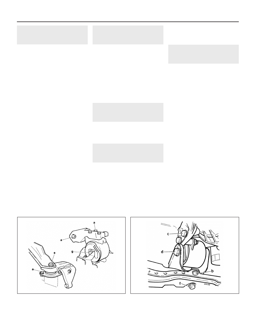
Engine mountings (with oiled threads):
Refer to illustrations 40.1a and 40.1b
(a) M8 . . . . . . . . . . . . . . . . . . . . . . . . . . . . . . . . . . . . . . . . . . . . . . . . .
25
18
(a) M10 . . . . . . . . . . . . . . . . . . . . . . . . . . . . . . . . . . . . . . . . . . . . . . . .
45
33
(b) . . . . . . . . . . . . . . . . . . . . . . . . . . . . . . . . . . . . . . . . . . . . . . . . . . . .
35
26
(c) . . . . . . . . . . . . . . . . . . . . . . . . . . . . . . . . . . . . . . . . . . . . . . . . . . . .
45
33
(d) . . . . . . . . . . . . . . . . . . . . . . . . . . . . . . . . . . . . . . . . . . . . . . . . . . . .
50
37
(e) . . . . . . . . . . . . . . . . . . . . . . . . . . . . . . . . . . . . . . . . . . . . . . . . . . . .
60
44
(f) . . . . . . . . . . . . . . . . . . . . . . . . . . . . . . . . . . . . . . . . . . . . . . . . . . . .
70
52
(g) . . . . . . . . . . . . . . . . . . . . . . . . . . . . . . . . . . . . . . . . . . . . . . . . . . . .
80
59
* When checking the connecting rod-to-crankshaft journal radial clearance using Plastigage, tighten only to 30Nm (22 lbf ft).
Engine repair procedures - 1.05 and 1.3 litre pre August 1985 2A•3
2A
1081 VW Golf & Jeta
1
General information
The 1.05 and 1.3 litre engines are of
four-cylinder, in-line, overhead camshaft type,
mounted transversely at the front of the
vehicle. The transmission is attached to the
left-hand side of the engine.
The crankshaft is of five bearing type and
separate thrustwashers are fitted to the
central main bearing to control crankshaft
endfloat.
The camshaft is driven by a toothed belt
which also drives the coolant pump. The
toothed belt is tensioned by moving the coolant
pump in its eccentric mounting. The valves are
operated from the camshaft by rocker fingers
which pivot on ball-head studs. The distributor
is driven by the camshaft and is located on the
left-hand end of the cylinder head.
The oil pump is of the eccentric gear type
driven from the end of the crankshaft.
The cylinder head is of crossflow design,
with the inlet manifold at the rear and the
exhaust manifold at the front.
The crankcase ventilation system is of the
positive type and consists of an oil separator
on the rear (coolant pipe side) of the cylinder
block, connected to the air cleaner by a
rubber hose. Vacuum from the air cleaner
provides a partial vacuum in the crankcase
and the piston blow-by gases are drawn
through the oil separator and into the engine
combustion chambers.
2
Major operations possible
with engine in vehicle
The following operations can be carried out
without having to remove the engine from the
vehicle:
a) Removal and servicing of the cylinder
head, camshaft and timing belt
b) Removal of the flywheel and crankshaft
rear oil seal (after removal of the gearbox)
c) Removal of the sump
d) Removal of the piston/connecting rod
assemblies (after removal of the cylinder
head and sump)
e) Renewal of the crankshaft front and rear
oil seals and the camshaft front oil seal
f) Renewal of the engine mountings
g) Removal of the oil pump
3
Major operation only
possible after removal of
engine from vehicle
The following operation can only be carried
out after removal of the engine from the vehicle:
a) Renewal of crankshaft main bearings
4
Method of engine removal
1 The engine, together with the gearbox,
must be lifted from the engine compartment
and the engine separated from the gearbox
on the bench. Two people will be needed.
2 A hoist of 150 kg capacity will be needed to
lift the engine approximately 1 metre. If the
hoist is not portable, then sufficient room
must be left behind the vehicle to push it back
out of the way so that the engine may be
lowered. Blocks will be needed to support the
engine after removal.
3 Ideally the vehicle should be over a pit. If
this is not possible then the body must be
supported on axle stands (see “Jacking and
vehicle support”) so that the front wheels may
be turned to undo the driveshaft nuts. The
left-hand shaft is accessible from above but
the right-hand shaft must be undone from
underneath. Removal of the gearshift linkage
can only be done from underneath, as can
removal of the exhaust pipe bracket. When all
tasks are complete, lower the vehicle back
onto its wheels.
4 A set of splined keys will be required to
remove and refit the socket-head bolts used
to secure certain items, such as the cylinder
head bolts.
5 Draining of oil and coolant is best done
away from the working area if possible. This
saves the mess made by spilled oil in the
place where you must work.
6 If an air conditioning system is fitted,
observe the precautions listed in Chapter 3.
5
Engine - removal
4
1 Disconnect the battery negative lead.
2 Remove the bonnet.
3 Drain the engine coolant and remove the
radiator, complete with cooling fan unit.
4 Remove the air cleaner unit.
5 Loosen the clip and disconnect the top
hose from the thermostat housing.
6 Place a container beneath the engine then
unscrew the sump drain plug and drain the oil
- see Chapter 1. When complete, clean the
drain plug and washer and refit it to the sump.
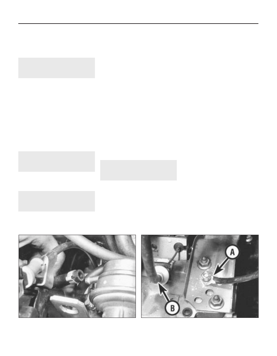
7 Identify the fuel supply and return hoses
then disconnect them from the fuel pump (see
illustration) and fuel reservoir/carburettor.
Plug the hoses to prevent fuel leakage.
8 Loosen the clip and disconnect the bottom
hose from the coolant pipe at the rear of the
engine.
9 Disconnect the accelerator cable and,
where applicable, the choke cable.
10 Disconnect the heater hoses from the
thermostat housing and rear coolant pipe.
11 Detach the following connections,
identifying each lead as it is disconnected to
avoid confusion on reassembly:
a) The oil pressure switches on the rear
(carburettor side) of the cylinder head
b) Inlet manifold preheating element line
connector
c) Thermo-switch leads (coolant hose
intermediate piece)
d) Distributor HT and LT leads
e) Starter motor
f) Temperature sender unit (thermostat
housing)
g) Fuel cut-off solenoid valve on carburettor
h) Earth strap to gearbox
12 Detach the wiring loom from the location
clip on the bottom hose and fold back out of
the way.
13 Disconnect and unclip the vacuum hoses
from the distributor and inlet manifold as
necessary.
14 Disconnect the clutch cable (see
illustration).
15 Disconnect the exhaust downpipe from
the exhaust manifold.
16 Disconnect the speedometer cable from
the gearbox and place it on one side.
17 Apply the handbrake then jack up the
front of the vehicle and support it on axle
stands (see “Jacking and vehicle support”).
18 Remove the screw from the shift rod
coupling and ease the coupling from the rod
(see illustration). The screw threads are
coated with a liquid locking agent and if
2A•4 Engine repair procedures - 1.05 and 1.3 litre pre August 1985
1081 VW Golf & Jeta
5.7 Detach hoses from fuel pump
5.14 Earth lead (A) and clutch cable (B)
difficulty is experienced, it may be necessary
to heat up the coupling with a blowlamp whilst
observing the necessary fire precautions.
Note that once removed this screw should be
renewed.
19 Note its orientation then withdraw the shift
rod coupling.
20 Unbolt the exhaust steady bracket from
the downpipe and clutch housing/starter
motor.
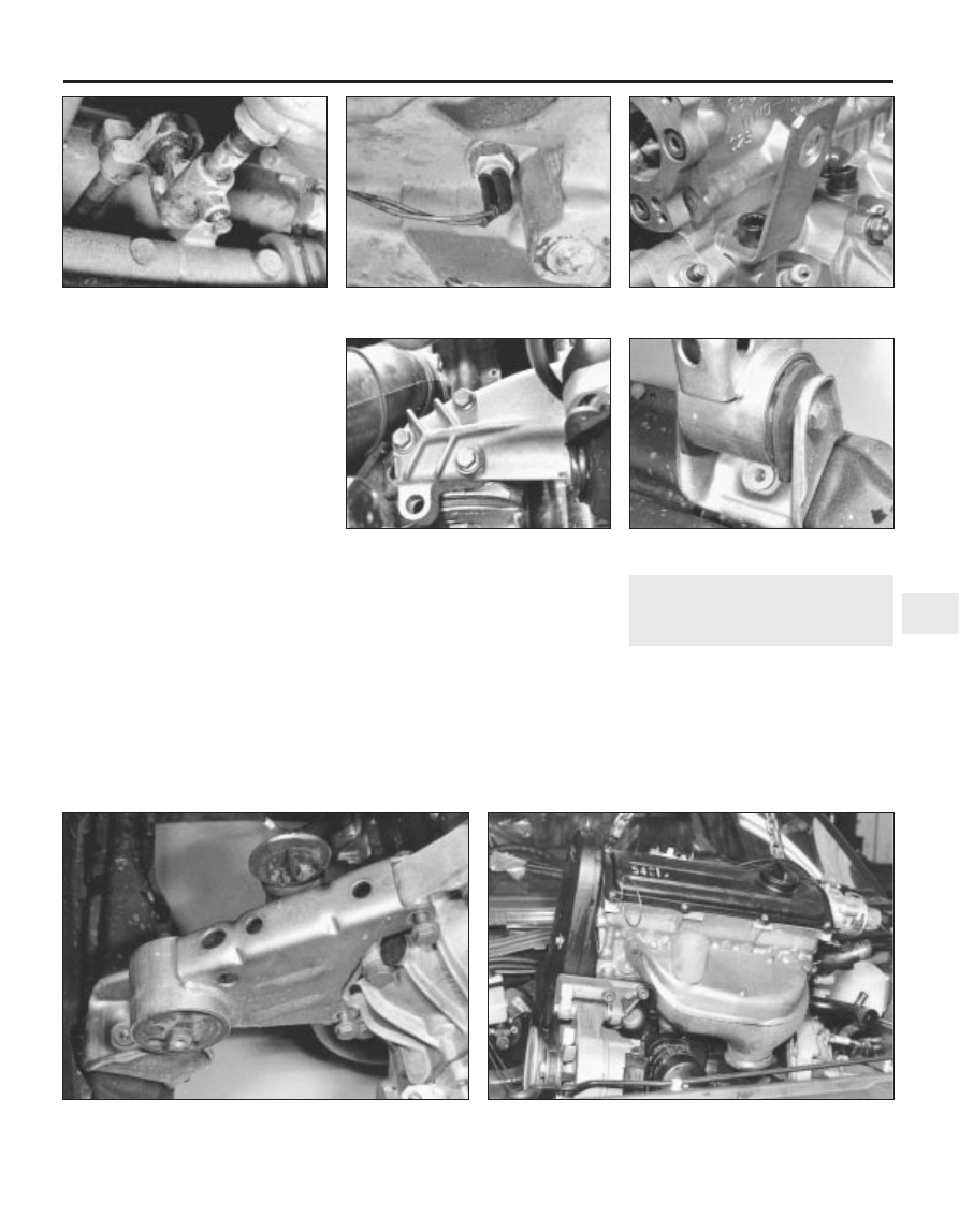
21 Detach the reversing light switch lead
(see illustration).
22 Unbolt the driveshafts from the drive
flanges and tie them to one side with wire.
23 Attach a suitable hoist to the engine lifting
eye brackets (one at each end of the cylinder
head on the carburettor side) (see
illustration). Take the weight of the
engine/gearbox unit.
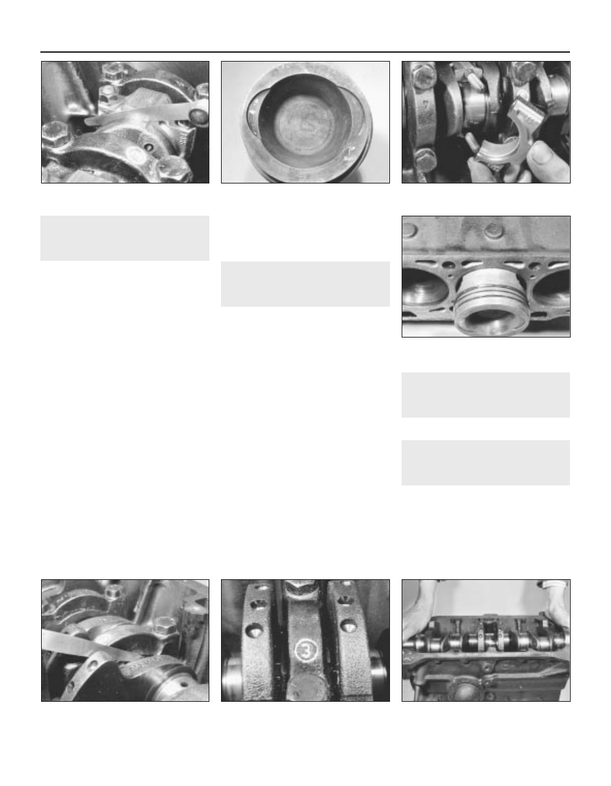
24 Working from above, undo the three
engine mounting/bearer retaining bolts
(underneath the carburettor) (see illustration).
25 Undo and remove the gearbox mounting
bolt (rear left side of engine compartment).
26 Undo and remove the front engine
mounting bolt and then remove the bolts
securing the bracket to the engine. Withdraw
the mounting (see illustrations).
27 Before lifting out the engine/gearbox unit,
get an assistant to hold the engine steady and
help guide it clear of surrounding components
as it is removed.
28 Lift the engine/gearbox unit from the
engine compartment (see illustration) while
turning it as necessary to clear the internally
mounted components. Make sure that all
wires, cables and hoses have been
disconnected.
29 Lower the unit onto a workbench or large
piece of wood placed on the floor.
6
Engine/gearbox - separation
3
1 The engine/gearbox unit must be
supported so that the gearbox can be eased
away from it. Either support the engine on
blocks so that the gearbox overhangs the
bench, or do the job while the engine and
gearbox are on the hoist.
2 Detach the lead from the alternator then
unclip the lead from the locating clips on the
sump side walls.
Engine repair procedures - 1.05 and 1.3 litre pre August 1985 2A•5
2A
5.18 Shift rod coupling screw
5.21 Reversing light switch
5.23 Engine lifting eye
5.24 Engine mounting/bearer - right-hand
5.26a Undo front mounting through-bolt
1081 VW Golf & Jeta
5.26b Unbolt and remove mounting unit
5.28 Lifting out engine/gearbox unit
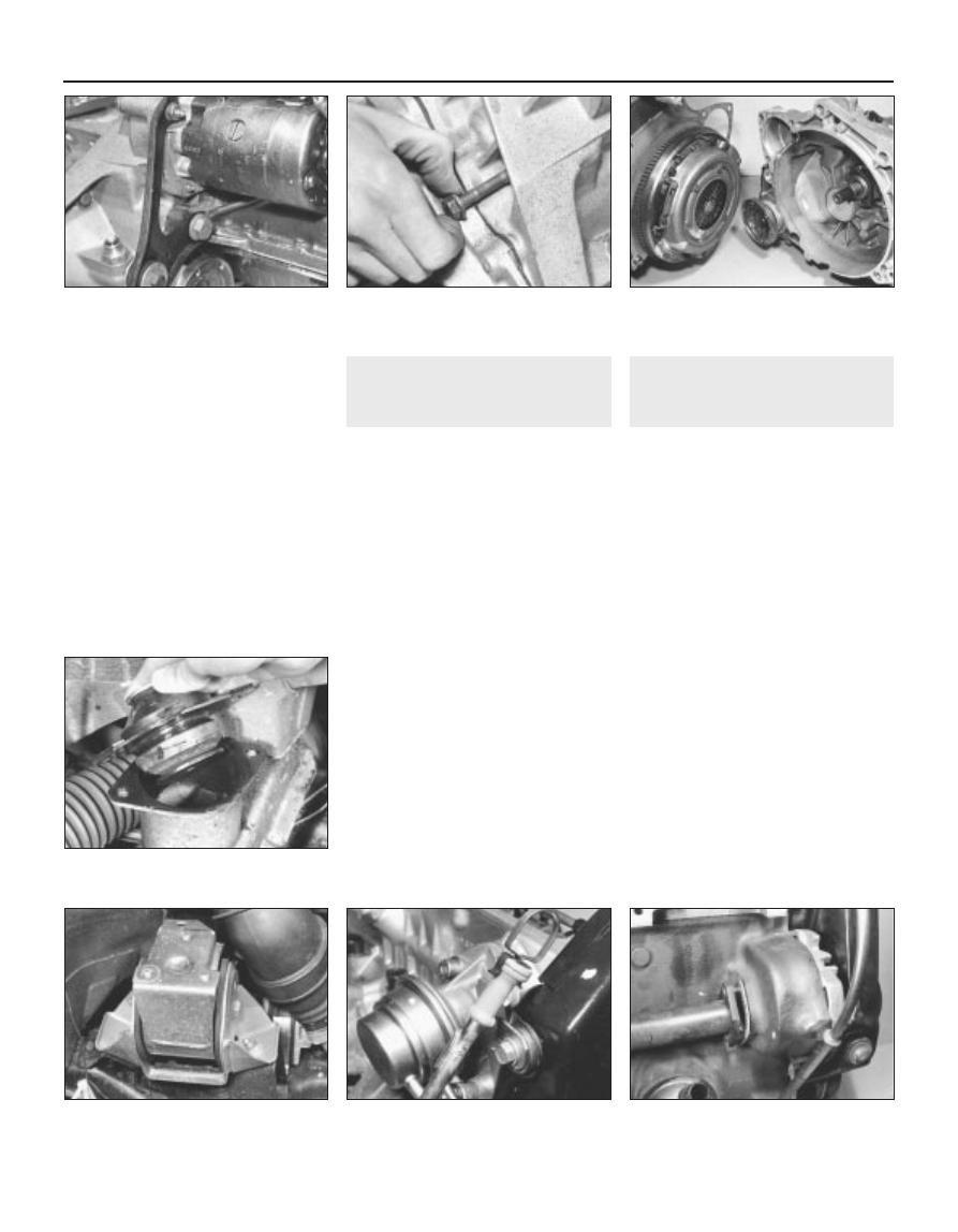
3 Because the rear bearing of the starter
armature is in the bellhousing, it is necessary
to remove the starter before separating the
engine and gearbox. If not already removed
when unbolting the starter motor, also detach
the exhaust pipe support bracket (see
illustration).
4 Detach the coolant pipe at its flange on the
rear side of the coolant pump and at the
clutch housing.
5 Undo the clutch housing belly plate bolt
and withdraw the plate.
6 Undo and remove the remaining
engine-to-gearbox securing bolts then pull the
gearbox free. Do not insert wedges or you will
damage the facing. Tap the gearbox gently
and wriggle it off the two dowels which locate
it. The intermediate plate will remain in
position (see illustrations).
7
Engine dismantling - general
information
1 If possible, mount the engine on a stand for
the dismantling procedure, but failing this,
support it in an upright position with blocks of
wood.
2 Cleanliness is most important. If the engine
is dirty, it should be cleaned with paraffin
while keeping it in an upright position.
3 Avoid working with the engine directly on a
concrete floor as grit presents a real source of
trouble.
4 As parts are removed, clean them in a
paraffin bath. Do not immerse parts with
internal oilways in paraffin as it is difficult to
remove. Clean oilways with nylon pipe
cleaners.
5 Obtain suitable containers to hold small
items. This will help when reassembling the
engine and also prevent possible loss.
6 Obtain complete sets of gaskets when the
engine is being dismantled but retain the old
gaskets with a view to using them as a pattern
to make a replacement if a new one is not
available.
7 When possible, refit nuts, bolts and
washers in their location after being removed.
This helps to protect the threads and will also
be helpful when reassembling the engine.
8 Retain unserviceable components in order
to compare them with the new parts supplied.
8
Engine ancillary components
- removal
3
With the engine removed from the vehicle
and separated from the gearbox, the
externally mounted ancillary components
should now be removed before dismantling
begins. The removal sequence need not
necessarily follow the order given:
a) Alternator and drivebelt
b) Inlet manifold and carburettor
c) Exhaust manifold
d) Distributor
e) Fuel pump
f) Thermostat
g) Clutch
h) Crankcase ventilation hose
i) Distributor cap and spark plugs
j) Oil filter
k) Engine mountings (see illustrations)
l) Dipstick (see illustration)
m) Oil pressure switches
n) Coolant temperature thermo-switch
o) Alternator mounting bracket and engine
earth lead
p) Engine rear coolant pipe (see illustration)
2A•6 Engine repair procedures - 1.05 and 1.3 litre pre August 1985
6.3 Starter motor and exhaust support
bracket
6.6a Undo securing bolts (recessed bolt
shown) . . .
6.6b . . . then separate engine and
transmission
8.1b Right-hand rear mounting viewed
from above
8.1a Lift the mounting away
8.1c Engine dipstick and tube
8.1d Removing engine rear coolant pipe
1081 VW Golf & Jeta
9
Cylinder head - removal
3
1 If the engine is still in the vehicle, first carry
out the following operations:
a) Disconnect the battery negative lead
b) Remove the air cleaner and fuel pump
c) Drain the cooling system and remove the
top hose and thermostat
d) Remove the distributor and spark plugs
e) Remove the inlet and exhaust manifolds.
If necessary, this can be carried out with
the cylinder head on the bench
f) Disconnect the wiring from the coolant
temperature sender and oil pressure
switch
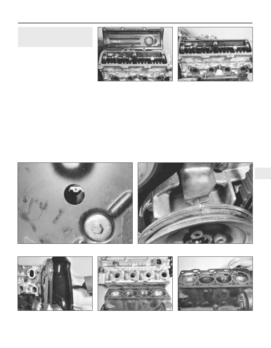
2 Unscrew the nuts and bolts from the valve
cover and remove the cover together with the
gasket and reinforcement strips (see
illustrations).
3 Turn the engine until the indentation in the
camshaft sprocket appears in the TDC hole in
the timing cover and the notch in the
crankshaft pulley is aligned with the TDC
pointer on the front of the oil pump (see
illustrations). Now turn the crankshaft one
quarter of a turn anti-clockwise so that none
of the pistons are at TDC.
4 Unbolt and remove the timing cover (see
illustration), noting that the dipstick tube and
earth lead are fitted to the upper bolts. On
some later 1.3 litre models, it is necessary to
remove the crankshaft pulley to remove the
lower timing belt cover. Pull the dipstick tube
from the cylinder block.
5 Using a socket through the hole in the
camshaft sprocket, unscrew the timing cover
plate upper retaining bolt.
6 Loosen the coolant pump retaining bolts,
then turn the pump body clockwise to release
the tension from the timing belt. Remove the
timing belt from the camshaft sprocket.
7 Remove the bolts and withdraw the timing
cover plate, followed by the coolant pump if
required.
8 Using a splined key, unscrew the cylinder
head bolts half a turn at a time in the reverse
order to that shown for tightening. Note the
location of the engine lifting hooks.
9 Lift the cylinder head from the block (see
illustration). If it is stuck, tap it free with a
wooden mallet. Do not insert a lever as
damage will occur to the joint faces.
10 Remove the gasket from the cylinder
block (see illustration).
Engine repair procedures - 1.05 and 1.3 litre pre August 1985 2A•7
2A
9.2a Removing valve cover. . .
9.2b . . . and gasket
9.4 Removing timing cover
9.9 Removing cylinder head . . .
9.10 . . . and gasket
1081 VW Golf & Jeta
9.3a TDC mark on camshaft sprocket and pointer
9.3b Crankshaft pulley notch aligned with TDC pointer
10 Camshaft - removal
3
1 If the engine is still in the vehicle, first carry
out the following operations:
a) Disconnect the battery negative lead
b) Remove the air cleaner and fuel pump
c) Remove the distributor and spark plugs
2 If the cylinder head is still fitted to the
engine, first carry out the procedure
described in paragraphs 3 to 6 inclusive.
3 Unscrew the nuts and bolts from the valve
cover and remove the cover together with the
gasket and reinforcement strips.
4 Turn the engine until the indentation in the
camshaft sprocket appears in the TDC hole in
the timing cover and the notch in the
crankshaft pulley is aligned with the TDC
pointer on the front of the oil pump. Now turn
the crankshaft one quarter of a turn
anti-clockwise so that none of the pistons are
at TDC.
5 Unbolt and remove the timing cover, noting
that the dipstick tube and earth lead are fitted
to the upper bolts. On some later 1.3 litre
models, it is necessary to remove the
crankshaft pulley to remove the lower timing
belt cover.
6 Loosen the coolant pump retaining bolts,
then turn the pump body clockwise to release
the tension from the timing belt. Remove the
timing belt from the camshaft sprocket.
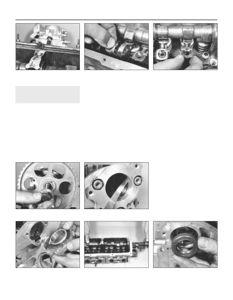
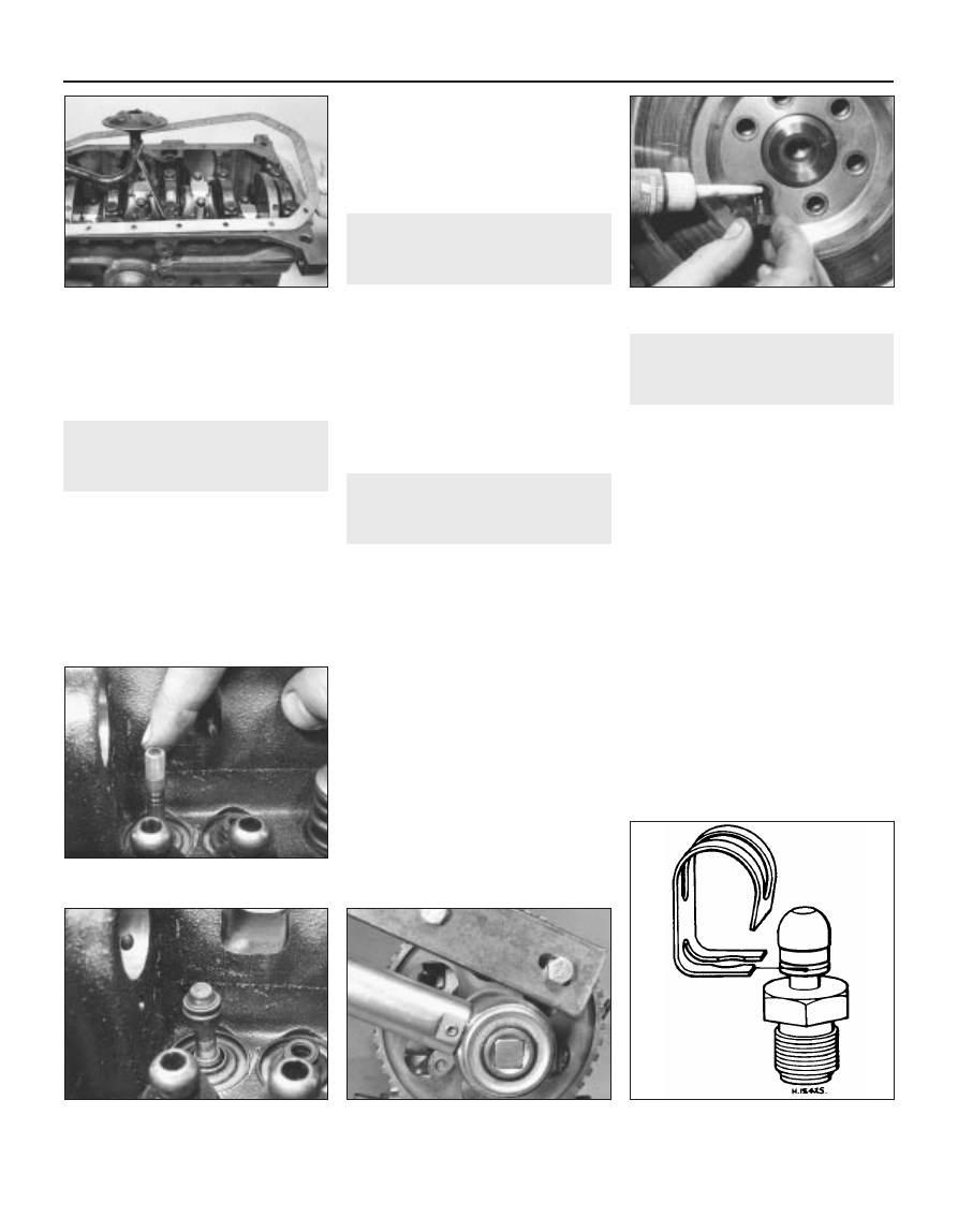
7 Prise the oil spray tube from the top of the
cylinder head (see illustration).
8 Note how the cam follower clips are fitted
then prise them from the ball-studs (see
illustration).
9 Identify each cam follower for location then
remove each one by levering with a
screwdriver. Make sure that the peak of the
relevant cam is pointing away from the
follower first by turning the camshaft as
necessary (see illustration).
10 Unscrew the camshaft sprocket bolt and
remove the spacer (see illustration). The
sprocket can be held stationary using a metal
bar with two bolts, with one bolt inserted in a
hole and the other bolt resting on the outer rim
of the sprocket.
11 Tap the sprocket from the camshaft with a
wooden mallet and prise out the Woodruff
key.
12 Using feeler blades, check the camshaft
endfloat by inserting the blade between the
end of the camshaft and distributor flanges
(see illustration). If it is more than the amount
specified, the components will have to be
checked for wear and renewed as necessary.
13 Using an Allen key, unscrew the bolts and
remove the distributor flange (see
illustration). Remove the gasket.
14 Carefully slide the camshaft from the
cylinder head, taking care not to damage the
three bearing surfaces as the lobes of the
cams pass through them (see illustration).
15 Prise the camshaft oil seal from the
cylinder head (see illustration).
2A•8 Engine repair procedures - 1.05 and 1.3 litre pre August 1985
10.7 Removing oil spray tube
10.8 Removing a cam follower clip
10.9 Removing a cam follower
10.13 Removing distributor flange
10.14 Withdrawing camshaft
10.10 Removing camshaft sprocket bolt
(early type sprocket shown)
10.12 Checking camshaft endfloat
10.15 Removing camshaft oil seal
1081 VW Golf & Jeta
11 Cylinder head - dismantling
and overhaul
3
Dismantling
1 Remove the cylinder head and camshaft, as
described in the previous Sections.
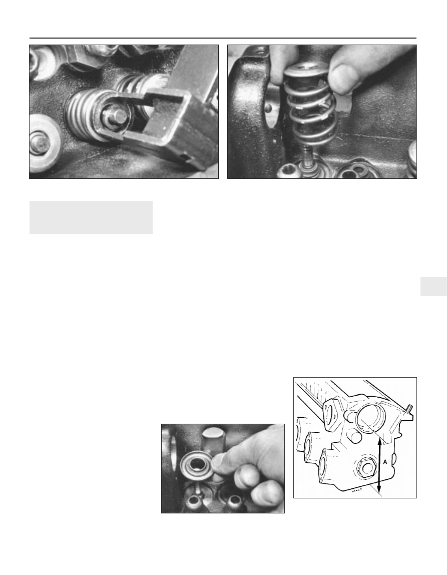
2 Using a valve spring compressor, compress
each valve spring in turn until the split collets
can be removed. Release the compressor and
remove the retainers and springs (see
illustrations). If the retainers are difficult to
remove, do not continue to tighten the
compressor but gently tap the top of the tool
with a hammer. Always make sure that the
compressor is held firmly over the retainer.
3 Remove each valve from the cylinder head,
keeping them identified for location.
4 Prise the valve seals from the valve guides
and remove the lower spring seats (see
illustration).
5 Do not remove the cam follower ball-studs
unless they are unserviceable. They are likely
to be seized in the head.
Overhaul
6 Use a scraper to carefully remove any
carbon from the cylinder head. Remove all
traces of gasket then wash the cylinder head
thoroughly in paraffin and wipe dry.
7 Use a straight-edge and feeler blade to
check that the cylinder head mating surface is
not distorted. If it is, then it must be
resurfaced by a suitably equipped engineering
works. If the cylinder head face is to be
resurfaced, this will necessitate the valve
seats being re-cut so that they are recessed
deeper by an equivalent amount to that
machined from the cylinder head. This is
necessary to avoid the possibility of the valves
coming into contact with the pistons and
causing serious damage and is a task to be
entrusted to a suitably equipped engine
recondition specialist. (see illustration).
8 Examine the valve heads for pitting and
burning. Renew any valve which is badly
burnt. Examine the valve seats at the same
time. If the pitting is very slight, it can be
removed by grinding the valve heads and
seats together with coarse, then fine, grinding
paste. Note that the exhaust valves should not
be re-cut, they should be renewed if the
sealing face is excessively grooved as a result
of regrinding.
9 Where excessive pitting has occurred, the
valve seats must be re-cut or renewed by a
specialist.
10 Valve grinding is carried out as follows.
Place the cylinder head upside down on a
bench with a block of wood at each end.
Smear a trace of coarse carborundum paste
on the seat face and press a suction grinding
tool onto the valve head. With a semi-rotary
action, grind the valve head to its seat, lifting
the valve occasionally to redistribute the
grinding paste. When a dull matt even surface
is produced on both the valve seat and the
valve, wipe off the paste and repeat the
process with fine carborundum paste as
before. A light spring placed under the valve
head will greatly ease this operation. When a
smooth unbroken ring of light grey matt finish
is produced on both the valve and seat, the
grinding operation is complete.
11 Scrape away all carbon from the valve
head stem and clean away all traces of
grinding compound. Clean the valves and
seats with a paraffin-soaked rag, then wipe
with a clean rag.
12 Check for wear in the valve guides. This
may be detected by fitting a new valve in the
guide and checking the amount that the rim of
the valve will move sideways when the top of
the valve stem is flush with the top of the
valve guide. The rock limit for the inlet valve is
1.0 mm and 1.3 mm for the exhaust valve.
This can be measured with feeler blades if you
use a clamp as a datum but it must be with a
new valve. If the rock is at or below this limit
with your old valve then this indicates that the
existing guide(s) do not need renewal. Check
each valve guide in turn but note that the inlet
and exhaust valve stem dimensions differ, so
do not get them confused. If the rock exceeds
the limit with a new valve, this will indicate the
need for new valve guides as well. The
removal and refitting of new guides is a task
which must be entrusted to a specialist.
Engine repair procedures - 1.05 and 1.3 litre pre August 1985 2A•9
2A
11.4 . . . and valve spring lower seats
11.7 Measure cylinder head depth
between points indicated
Minimum allowable depth a = 119.3 mm
1081 VW Golf & Jeta
11.2a Compressing a valve spring to remove split collets
11.2b Removing valve springs and retainers . . .
13 If possible, compare the length of the
valve springs with new ones and renew them
as a set if any are shorter.
14 If the engine is still in the vehicle, clean the
piston crowns and cylinder bore upper edges
but make sure that no carbon drops between
the pistons and bores. To do this, locate two
of the pistons at the top of their bores and
seal off the remaining bores with paper and
masking tape. Press a little grease between
the two pistons and their bores to collect any
carbon dust which can be wiped away when
the piston is lowered. To prevent carbon
build-up, polish the piston crown with metal
polish but remove all traces of the polish
afterwards.
12 Timing belt and sprockets -
removal
3
1 If the engine is still in the vehicle, first carry
out the following operations:
a) Disconnect the battery negative lead
b) Remove the air cleaner
c) Remove the alternator drivebelt
2 Turn the engine until the indentation in the
camshaft sprocket appears in the TDC hole in
the timing cover and the notch in the
crankshaft pulley is aligned with the TDC
pointer on the front of the oil pump.
3 Unbolt and remove the timing cover, noting
that the dipstick tube and earth lead are fitted
to the upper bolts. On some later 1.3 litre
models, it is necessary to remove the
crankshaft pulley to remove the lower timing
belt cover.
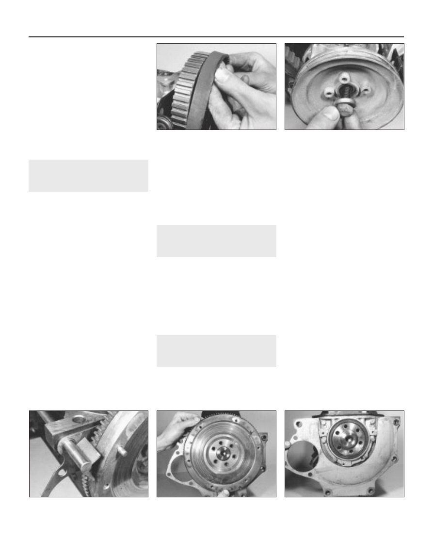
4 Loosen the coolant pump retaining bolts,
then turn the pump body clockwise to release
the tension from the timing belt. Remove the
timing belt from the camshaft sprocket (see
illustration).
5 Using an Allen key, unbolt the pulley from
the crankshaft sprocket then remove the
timing belt.
6 To remove the camshaft sprocket, unscrew
the bolt and remove the spacer. Tap off the
sprocket and remove the Woodruff key. Do
not turn the camshaft. The sprocket can be
held stationary using a metal bar with two
bolts, with one bolt inserted through a
sprocket hole and the other bolt resting on the
outer rim.
7 To remove the crankshaft sprocket,
unscrew the bolt and lever the sprocket from
the crankshaft (see illustration). Do not turn
the crankshaft otherwise the pistons may
touch the valve heads. Hold the crankshaft
stationary with a lever inserted in the starter
ring gear (remove the starter as applicable).
Remove the Woodruff key.
13 Flywheel - removal
3
1 Remove the clutch.
2 Hold the flywheel stationary with a lever or
angle iron (see illustration) engaged with the
starter ring gear.
3 Unscrew the bolts and lift the flywheel from
the crankshaft (see illustration).
4 Remove the engine plate from the cylinder
block (see illustration).
5 The flywheel bolts must be renewed once
they are removed.
14 Crankshaft oil seals - renewal
3
Front seal
1 Remove the crankshaft sprocket.
2 If available, use VW tool 2085 to remove the
seal from the oil pump housing. Removal of
the seal with the engine and oil pump in
position in the vehicle can prove difficult
without the special tool. In this instance, an
alternative method is to drill two holes,
diagonally opposed to each other in the seal,
insert two self-tapping screws and then pull
on the screws using grips to withdraw the
seal. If using this method, care must be taken
not to drill into the housing.
3 If the oil pump is removed from the engine,
the seal can be prised out and a new item
fitted - see illustration 31.1.
4 Clean the recess in the oil pump.
5 Smear a little clean engine oil on the lip and
outer edge of the new seal, then fit it with VW
tool 10-203 or by tapping it in with a suitable
metal tube .
6 Refit the crankshaft sprocket.
Rear seal
7 Remove the flywheel.
Method 1
8 Drill two diagonally opposite holes in the
seal. Insert two self-tapping screws and pull
out the seal with grips.
9 Clean the recess in the housing.
10 Smear a little clean engine oil on the lip
and outer edge of the new seal then tap it into
the housing using a suitable metal tube
11 Refit the flywheel.
Method 2
12 Remove the sump.
13 Unscrew the bolts and withdraw the
housing from the dowels on the cylinder
block. Remove the gasket (see illustrations).
2A•10 Engine repair procedures - 1.05 and 1.3 litre pre August 1985
12.4 Releasing timing belt from camshaft
sprocket
12.7 Removing crankshaft sprocket bolt
and washer
13.2 One method of holding the flywheel
stationary
13.3 Removing flywheel
13.4 Removing engine plate
1081 VW Golf & Jeta
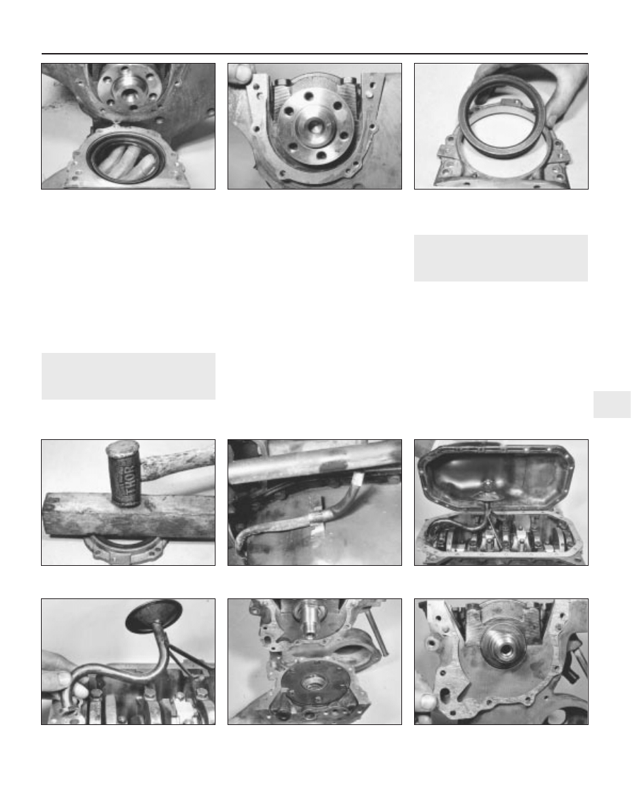
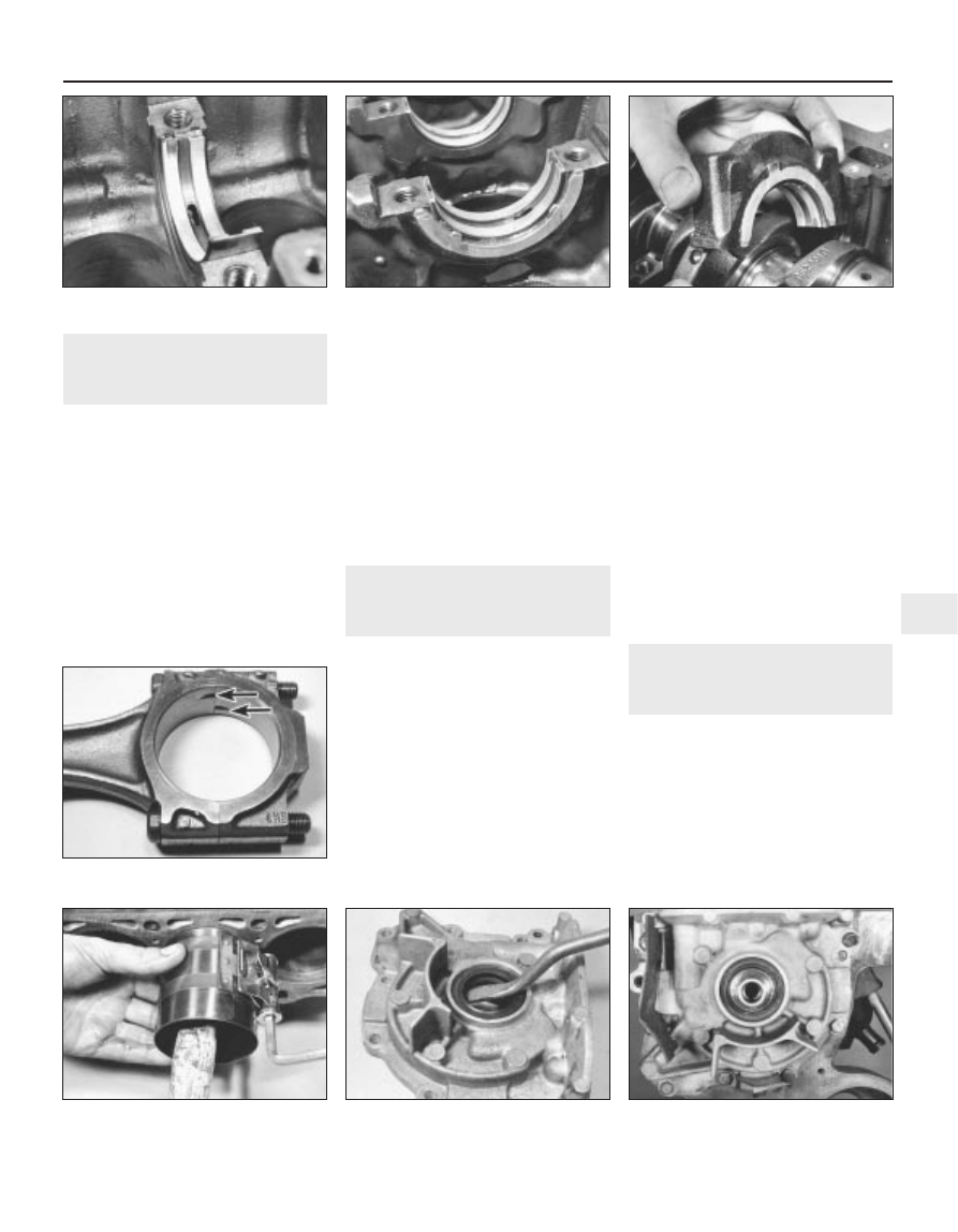
14 Support the housing and drive out the oil
seal (see illustration).
15 Clean the recess in the housing.
16 Smear a little clean engine oil on the lip
and outer edge of the new seal then tap it into
the housing using a block of wood (see
illustration).
17 Clean the mating faces then refit the
housing, together with a new gasket, and
tighten the bolts evenly in diagonal sequence.
18 Refit the sump and flywheel.
15 Sump - removal
3
1 If the engine is still in the vehicle, first carry
out the following operations:
a) Jack up the front of the vehicle and
support it on axle stands (see “Jacking
and vehicle support”). Apply the
handbrake
b) Disconnect the right-hand side driveshaft
and the exhaust system
c) Unclip the alternator wire from the sump
(see illustration)
d) Drain the engine oil into a suitable
container. Clean the drain plug and
washer and refit it, tightening to the
specified torque
2 Unscrew the bolts and withdraw the sump
from the cylinder block (see illustration). If it
is stuck, lever it away or cut through the
gasket with a knife .
3 Scrape the gasket from the sump and
cylinder block.
16 Oil pump - removal
3
1 Remove the timing belt and crankshaft
sprocket.
2 Remove the sump.
3 Unbolt and remove the pick-up tube and
strainer from the oil pump and cylinder block.
Remove the flange gasket (see illustration).
4 Unscrew the bolts and withdraw the oil
pump from the dowels on the front of the
cylinder block. Note that the timing pointed
bracket is located on the two upper central
bolts and the timing belt guard on the two
left-hand side bolts. Remove the gasket (see
illustrations).
Engine repair procedures - 1.05 and 1.3 litre pre August 1985 2A•11
2A
14.13a Withdrawing crankshaft rear oil
seal housing . . .
14.13b . . . and gasket
14.14 Remove crankshaft rear oil seal
from housing
16.3 Removing oil pump pick-up tube and
strainer
16.4a Removing oil pump . . .
16.4b . . . and gasket
14.16 Installing new crankshaft rear oil
seal
15.1 Alternator wire clip on sump
15.2 Removing the sump
1081 VW Golf & Jeta
17 Pistons and connecting rods
- removal
3
1 Remove the cylinder head.
2 Remove the sump.
3 Unbolt and remove the pick-up tube and
strainer from the oil pump and cylinder block.
Remove the flange gasket.
4 Using a feeler blade, check that the
connecting rod big-end endfloat on each
crankpin is within the specified limits (see
illustration). If not, the components must be
checked for wear and renewed as necessary.
5 Check the big-end caps and connecting
rods for identification marks, if necessary use
a centre punch to mark them for location and
position. Note that the cut-outs in the
connecting rods and caps face the timing belt
end of the engine. The arrows on the piston
crown also face the timing belt (see
illustration).
6 Turn the crankshaft so that No 1 crankpin is
at its lowest point.
7 Unscrew the big-end nuts and tap free the
cap, together with its bearing shell (see
illustration).
8 Using the handle of a hammer, tap the
piston and connecting rod from the bore and
withdraw it from the top of the cylinder block
(see illustration).
9 Loosely refit the cap to the connecting rod.
10 Repeat the procedure given in paragraphs
7 to 9 on No 4 piston and connecting rod,
then turn the crankshaft through half a turn
and repeat the procedure on No 2 and 3
pistons.
11 Note that during reassembly, the
connecting rod bolts must be renewed.
18 Crankshaft and main
bearings - removal
3
1 Disconnect the connecting rods from the
crankshaft. It is not essential to remove the
pistons or, therefore, to remove the cylinder
head.
2 Remove the oil pump and the rear oil seal
housing.
3 Using a feeler blade, check that the
crankshaft endfloat is within the specified
limits (see illustration). Insert the feeler blade
between the centre crankshaft web and the
thrustwashers. This will indicate whether new
thrustwashers are required or not.
4 Check that the main bearing caps are
identified for location and position. There
should be a cast number in the crankcase
ventilation pipe/coolant coolant pipe side of
the caps, numbered from the timing belt end
of the engine (see illustration).
5 Unscrew the bolts and tap the main bearing
caps free. Keep the bearing shells and where
fitted, the thrustwashers identified for
position.
6 Lift the crankshaft from the crankcase and
remove the remaining bearing shells and
thrustwashers. Keep them identified for
position
(see illustration).
19 Oil filter - renewal
1
Refer to Chapter 1, Section 18
20 Examination and renovation
- general information
With the engine completely stripped, clean
all the components and examine them for
wear. Each part should be checked and
where necessary renewed or renovated, as
described in the following Sections. Renew
main and big-end shell bearings as a matter of
course, unless you know that they have had
little wear and are in perfect condition
2A•12 Engine repair procedures - 1.05 and 1.3 litre pre August 1985
17.4 Checking connecting rod endfloat
17.5 Piston crown showing arrow which
points to timing belt end of engine
17.7 Withdrawing a big-end cap
18.3 Checking crankshaft endfloat
17.8 Removing a piston
18.4 Crankshaft main bearing cap
numbering
18.6 Removing crankshaft
1081 VW Golf & Jeta
21 Crankshaft and bearings -
examination and renovation
5
1 Examine the bearing surfaces of the
crankshaft for scratches or scoring. Using a
micrometer, check each journal and crankpin
for ovality. Where this is found to be in excess
of 0.17 mm, the crankshaft will have to be
reground and undersize bearings fitted.
2 Crankshaft regrinding should be carried out
by a specialist who will normally supply the
matching undersize main and big-end shell
bearings.
3 If crankshaft endfloat is more than the
maximum specified amount, new centre main
bearing shells with side flanges will have to be
fitted to replace the thrustwashers. These are
usually supplied together with the main and
big-end bearings on a reground crankshaft.
22 Cylinder block/crankcase -
examination and renovation
5
1 The cylinder bores must be examined for
taper, ovality, scoring and scratches. Start by
examining the top of the bores. If these are
worn, a slight ridge will be found which marks
the top of the piston ring travel. If the wear is
excessive, the engine will have had a high oil
consumption rate accompanied by blue
smoke from the exhaust.
2 If available, use an inside dial gauge to
measure the bore diameter just below the
ridge and compare it with the diameter at the
bottom of the bore, which is not subject to
wear. If the difference is more than 0.15 mm,
the cylinders will normally require reboring
with new oversize pistons fitted.
3 If cylinder bore wear does not exceed 0.20
mm, special oil control rings and pistons can
be fitted to restore compression and stop the
engine burning oil.
4 If new pistons are being fitted to old bores,
it is essential to roughen the bore walls
slightly with fine glasspaper to enable the new
piston rings to bed in properly.
5 Thoroughly examine the crankcase and
cylinder block for cracks and damage and use
a piece of wire to probe all oilways and
waterways to ensure that they are
unobstructed.
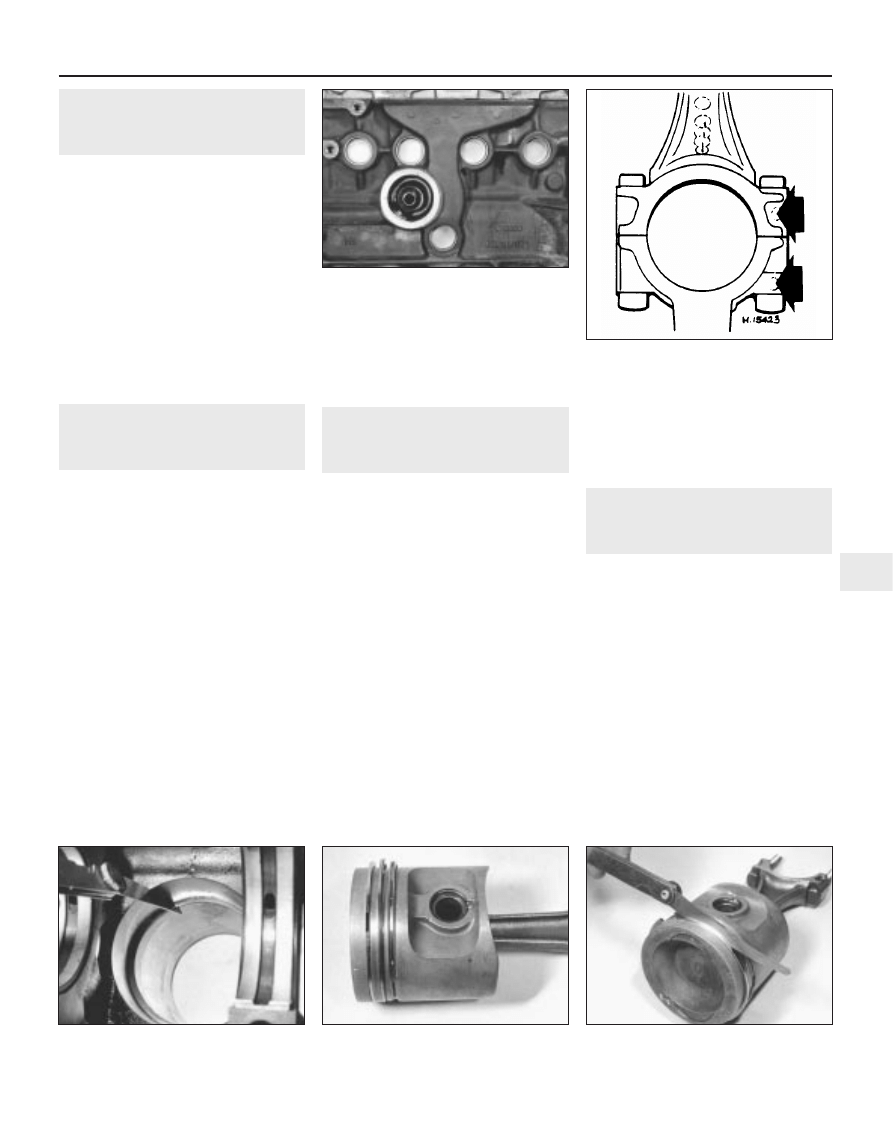
6 Check the core plugs for leaks and security
(see illustration).
23 Pistons and connecting rods
- examination and renovation
4
1 Examine the pistons for ovality, scoring and
scratches. Check the connecting rods for
wear and damage.
2 To remove the pistons from the connecting
rods, first mark the two components in
relation to each other. The indentation on the
bearing end of the connecting rod faces the
same way as the arrow on the piston crown
(see illustration).
3 Prise out the circlips then dip the piston in
hot water. Press out the gudgeon pin and
separate the piston from the connecting rod.
4 Assemble the pistons in reverse order.
5 If new rings are to be fitted to the original
pistons, expand the old rings over the top of
the pistons by using three old feeler blades to
prevent the rings dropping into empty
grooves.
6 Before fitting the new rings, insert each of
them into the cylinder bore approximately
15.0 mm from the bottom and check that the
end gaps are as specified (see illustration).
7 When fitting the rings to the pistons, ensure
that the TOP markings face towards the
piston crown and arrange the end gaps at
120° intervals (see illustration). Using a feeler
blade, check that the clearance of each ring in
its groove is within the limits specified (see
illustration).
24 Oil pump - examination and
renovation
3
Note: The manufacturer does not supply any
clearances for checking oil pump gear wear,
so the pump must be assumed to be in good
order provided that oil pressure is as
specified. Pressure can only be checked with
the engine assembled and the task should be
entrusted to a VW garage. A visual
examination of the oil pump can be made as
follows:
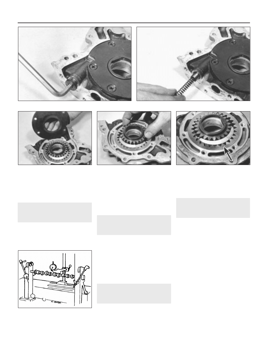
1 Using an Allen key, unscrew the relief valve
plug and extract the spring and plunger (see
illustrations).
2 Using an impact screwdriver, remove the
cross-head screws and withdraw the cover
from the pump (see illustration).
3 Remove the rotors, noting that the
indentation on the outer rotor faces the cover
(see illustrations).
Engine repair procedures - 1.05 and 1.3 litre pre August 1985 2A•13
2A
22.6 Core plugs in cylinder block
23.2 Indentations on big-end bearings
(arrowed) must face same way as arrow on
piston crown
23.6 Checking piston ring gaps
23.7a Space ring gaps at 120° intervals
23.7b Checking piston ring-to-groove wall
clearance
1081 VW Golf & Jeta
4 Clean the components in paraffin and wipe
dry, then examine them for wear and damage.
If evident, renew the oil pump complete but if
in good order, reassemble the pump in reverse
order and tighten the screws and plug.
25 Flywheel - examination and
renovation
4
1 A damaged flywheel must be renewed.
2 Inspect the starter ring teeth. If these are
chipped or worn it is possible to renew the
starter ring. This means heating the ring until it
may be separated from the flywheel, or
alternatively splitting it. A new ring must then be
shrunk on. If you know how to do this and you
can get a new ring, then the job can be done
but it is beyond the capacity of most owners.
3 Serious scoring on the flywheel clutch
facing again requires a new flywheel. Do not
attempt to clean the scoring off with a scraper
or emery.
26 Timing belt and sprockets -
examination and renovation
1
1 The timing belt should be renewed as a
matter of course at 40 000 miles (60 000 km),
see Chapter 1.
2 The full length of the timing belt must be
checked for signs of uneven wear, splitting or
oil contamination. Renew the belt if there is
the slightest doubt about its condition.
3 The camshaft and crankshaft sprockets do
not normally require renewal as wear takes
place very slowly.
27 Camshaft - examination and
renovation
3
Examine the camshaft bearing surfaces,
cam lobes and followers for wear. If wear is
excessive, renew the camshaft and followers.
Check the camshaft run-out by turning it
between fixed centres with a dial gauge on
the centre journal. If the run-out exceeds that
specified, renew the shaft (see illustration).
28 Engine reassembly - general
information
To ensure maximum life with minimum
trouble from a rebuilt engine, adhere to the
following:
a) Ensure that all components are spotlessly
clean
b) Ensure that all oilways are clear
c) Ensure lockwashers are fitted where
indicated
d) Lubricate all bearings and other working
surfaces thoroughly with clean engine oil
during assembly
e) Renew any bolts or studs with damaged
threads.
f) Gather together a torque wrench, oil can
and some clean rags
g) Obtain a set of engine gaskets and oil
seals, together with a new oil filter
2A•14 Engine repair procedures - 1.05 and 1.3 litre pre August 1985
24.2 Removing oil pump cover . . .
24.3a . . . and rotors
24.3b Outer rotor indentation (arrowed)
must face cover
27.2 Checking camshaft run-out
1081 VW Golf & Jeta
24.1a Unscrew relief valve plug . . .
24.1b . . . and remove spring and plunger
29 Crankshaft and main
bearings - refitting
3
1 Clean the backs of the bearing shells and
the bearing recesses in the cylinder block and
main bearing caps.
2 Press the main bearing shells into the
cylinder block and caps and oil them liberally
(see illustration).
3 Where thrustwashers are being refitted
(instead of a shouldered type No 3 main
bearing shell, a plain shell is used), smear the
washers with grease and stick them into
position on the side of the centre main
bearing and its cap (see illustration). The
washers must be fitted so that their oilways
face away from the bearings in the block and
cap.
4 Lower the crankshaft into position, then fit
the main bearing caps in their previously
noted positions (see illustration). Note that
the bearing shell lugs are adjacent to each
other.
5 Insert the bolts and tighten them evenly to
the specified torque. Check that the
crankshaft rotates freely then check that the
endfloat is within the specified limits by
inserting a feeler blade between the centre
crankshaft web and the thrustwashers or
bearing shoulder, as applicable.
6 Refit the rear oil seal bearing and oil pump
and reconnect the connecting rods.
30 Pistons and connecting rods
- refitting
3
1 As mentioned during removal, the
manufacturers recommend that the
connecting rod bolts be renewed. Assemble
the new bolts to the rods.
2 Clean the backs of the bearing shells and
the recesses in the connecting rods and
big-end caps.
3 Press the big-end bearing shells into the
connecting rods and caps in their correct
positions and oil them liberally (see
illustration).
4 Fit a ring compressor to No 1 piston then
insert the piston and connecting rod into No 1
cylinder (see illustration). With No 1 crankpin
at its lowest point, drive the piston carefully
into the cylinder with the wooden handle of a
hammer and at the same time, guide the
connecting rod into the crankpin. Make sure
that the arrow on the piston crown faces the
timing belt end of the engine.
5 Fit the big-end bearing cap in its previously
noted position then fit the nuts and tighten
them evenly to the specified torque.
6 Check that the crankshaft turns freely and
use a feeler blade to check that the
connecting rod endfloat is within the specified
limits.
7 Repeat the procedure given in paragraphs
3 to 5 for No 4 piston and connecting rod,
then turn the crankshaft through half a turn
and repeat the procedure for No 2 and 3
pistons.
8 If the engine is in the vehicle, refit the oil
pump pick-up tube and strainer, the sump
and the cylinder head.
31 Oil pump - refitting
3
1 Renew the oil seal in the oil pump housing
(see illustration).
2 Locate a new gasket on the dowels on the
front of the cylinder block.
3 Locate the oil pump on the block, making
sure that the inner rotor engages the flats on
the crankshaft. Do not damage the oil seal.
4 Insert the bolts, together with the timing
pointer bracket and timing belt guard, then
tighten them evenly to the specified torque
(see illustration).
Engine repair procedures - 1.05 and 1.3 litre pre August 1985 2A•15
2A
29.2 Fitting centre main bearing shell
29.3 Thrustwasher location on centre
main bearing
29.4 Fitting centre main bearing cap
30.3 Correct location of tabs on big-end
bearings (arrowed)
30.4 Using a piston ring compressor
31.1 Prising out oil pump oil seal
31.4 Fitted location of oil pump
1081 VW Golf & Jeta
5 Locate a new gasket on the flange face
then fit the pick-up tube and strainer. Insert
the bolts and tighten them to the specified
torque.
6 Refit the sump, timing belt and sprocket.
32 Sump - refitting
3
1 If applicable (ie. the engine has been
dismantled), refit the crankshaft rear oil seal
and housing.
2 Clean the mating faces of the sump and
cylinder block.
3 Locate the new gasket on the block (see
illustration) then fit the sump. Insert the sump
bolts and tighten them evenly in diagonal
sequence to the specified torque. If required,
the two bolts at the flywheel end of the sump
can be replaced by socket-headed bolts to
facilitate their removal with the engine in the
vehicle. Note that the tightening torque for the
replacement bolts is 8 Nm (6 Ibf ft).
4 If the engine is in the vehicle, replenish it
with oil, fasten the alternator wire to the sump
clip and lower the vehicle to the ground.
33 Flywheel - refitting
3
1 Locate the engine plate on the cylinder
block dowels.
2 Clean the mating faces of the flywheel and
crankshaft then locate the flywheel in position.
Note that the bolt holes only align in one
position as they are offset.
3 Apply locking fluid to the threads of new
bolts (see illustration) then insert and tighten
them in a diagonal sequence to the specified
torque while holding the flywheel stationary.
4 Refit the clutch.
34 Cylinder head - reassembly
3
1 Fit the valves into their correct locations in
the cylinder head.
2 Working on each valve at a time, locate the
valve spring lower seat in position.
3 Before fitting each valve seal, locate the
special plastic sleeve provided in the gasket
set over the valve stem in order to prevent
damage to the seal (see illustration).
4 Slide each new seal over the valve stem
and press it firmly onto the guide using a
metal tube (see illustration). Remove the
plastic sleeve.
5 Fit the spring and retainer over each valve
stem, then compress the spring with the
compressor and insert the split collets.
Release the compressor and remove it.
6 Refit the camshaft.
35 Camshaft - refitting
3
1 Smear a little clean engine oil on the lip and
outer edge of the camshaft oil seal then drive
it squarely into the cylinder head with a block
of wood.
2 Oil the camshaft bearing surfaces then slide
the camshaft into position, taking care not to
damage the oil seal.
3 Fit the distributor flange, together with a
new gasket, and tighten the socket-head
bolts.
4 Using a feeler blade, check that the
camshaft endfloat is as specified.
5 Fit the Woodruff key then fit the sprocket to
the camshaft followed by the spacer and bolt.
Tighten the bolt while holding the sprocket
stationary with a metal bar and two bolts (see
illustration).
6 Fit the cam followers by turning the
camshaft so that the relevant cam lobe peak
is pointing away from the valve, then tap the
follower between the valve stem and cam and
onto the ball-stud.
7 Slide the cam follower clips into the
grooves on the ball studs and locate the
upper ends on the cam followers (see
illustration).
2A•16 Engine repair procedures - 1.05 and 1.3 litre pre August 1985
32.3 Fitting sump gasket
33.3 Applying liquid locking fluid to
flywheel bolts
34.3 Locate plastic sleeve on valve
stem . . .
34.4 . . . then fit the new oil seal
35.5 Method of tightening camshaft
sprocket bolt
35.7 Cam follower clip and groove in
ball-stud
1081 VW Golf & Jeta

8 Adjust the valve clearances.
9 Turn the camshaft so that the indentation in
the sprocket is pointing downwards and in
line with the pointer on the timing cover plate
(see illustration).
10 Turn the crankshaft a quarter of a turn
clockwise so that the notch in the crankshaft
pulley is aligned with the TDC pointer on the
front of the oil pump.
11 Fit the timing belt to the camshaft
sprocket and coolant pump.
12 Using a screwdriver in the coolant pump,
turn the pump anti-clockwise and tension the
timing belt until it can just be turned through
90° with the thumb and forefinger midway
between the camshaft sprocket and coolant
pump.
13 Tighten the coolant pump bolts when the
belt tension is correct and check the timing
marks are still aligned.
14 Fit the dipstick tube to the cylinder block.
15 Fit the timing cover, insert the bolts with
the earth lead and dipstick tube bracket, then
tighten the bolts.
16 Press the oil spray tube into the top of the
cylinder head.
17 Refit the valve cover with a new gasket,
locate the reinforcement strips and tighten the
nuts and bolts.
18 If the engine is in the vehicle, reverse the
preliminary procedures given in Section 10.
36 Cylinder head - refitting
3
1 Position Nos 1 and 4 pistons at TDC then
turn the crankshaft a quarter of a turn
anti-clockwise so that neither of the pistons is
at TDC.
2 Ensure that the faces of the cylinder head
and block are perfectly clean then locate the
new gasket on the block, making sure that all
oil and coolant holes are visible. The gasket
part number should be uppermost (see
illustration).
3 Lower the cylinder head onto the gasket
then insert the bolts together with the engine
lifting hooks.
4 Using a splined key, tighten the bolts in the
stages given in Specifications, using the
sequence shown (see illustration).
5 Refit the coolant pump, if applicable.
6 Fit the timing cover plate and insert the
coolant pump bolts loosely.
7 If required, refit the camshaft.
8 Refit and tighten the timing cover plate
upper retaining bolt.
9 If applicable, refit the crankshaft sprocket
and timing belt to the crankshaft (see
illustration).
10 Turn the camshaft so that the indentation
in the sprocket is aligned with the pointer on
the timing cover plate.
11 Turn the crankshaft a quarter of a turn
clockwise so that the notch in the crankshaft
pulley (temporarily refit if necessary) is aligned
with the TDC pointer on the front of the oil
pump.
12 Fit the timing belt to the camshaft
sprocket and coolant pump.
13 Using a screwdriver in the coolant pump,
turn the pump anti-clockwise and tension the
timing belt until it can just be turned through
90° with the thumb and forefinger midway
between the camshaft sprocket and coolant
pump (see illustration).
14 Tighten the coolant pump bolts when the
tension is correct and check that the timing
marks are still aligned.
15 Fit the dipstick tube to the cylinder block.
16 Fit the timing cover, insert the bolts with
the earth lead and dipstick tube bracket and
tighten the bolts.
17 Refit the valve cover with a new gasket,
locate the reinforcement strips and tighten the
nuts and bolts.
18 If the engine is in the vehicle, reverse the
preliminary procedures given in Section 9.
Engine repair procedures - 1.05 and 1.3 litre pre August 1985 2A•17
2A
35.9 Camshaft sprocket (later type) with
index mark aligned with timing cover TDC
pointer
36.2 Correct fitting of cylinder head
gasket
36.4 Cylinder head bolt tightening sequence
36.9 Fitting crankshaft sprocket and
timing belt
36.13 Tensioning timing belt
1081 VW Golf & Jeta
37 Timing belt and sprockets -
refitting
3
1 Fit the Woodruff key in the crankshaft and
tap the sprocket into position .
2 Insert the bolt and tighten it to the specified
torque while holding the crankshaft stationary
with a lever in the starter ring gear.
3 Fit the Woodruff key to the camshaft then fit
the sprocket followed by the spacer and bolt.
Tighten the bolt while holding the sprocket
stationary with a metal bar and two bolts.
4 Locate the timing belt on the crankshaft
sprocket then fit the pulley. Insert the bolts
and tighten them with an Allen key.
5 Turn the camshaft so that the indentation in
the sprocket is aligned with the pointer on the
timing cover plate. Check that the notch in the
crankshaft pulley is aligned with the TDC
pointer on the front of the oil pump
6 Fit the timing belt to the camshaft sprocket
and coolant pump.
7 Using a screwdriver in the coolant pump,
turn the pump anti-clockwise and tension the
timing belt until it can just be turned through
90° with the thumb and forefinger midway
between the camshaft sprocket and coolant
pump.
8 Tighten the coolant pump bolts when the
belt tension is correct and check that the
timing marks are still aligned.
9 Fit the timing cover, insert the bolts with the
earth lead and dipstick tube bracket, then
tighten the bolts.
10 If the engine is in the vehicle, reverse the
preliminary procedures given in Section 12.
38 Valve clearances - checking
and adjustment
3
1 The valve clearances can be checked and
adjusted with the cylinder head removed
(prior to refitting after overhaul) or in the
normal manner described in Section 12 of
Chapter 1.
2 There are two specified valve clearance
settings, these being for a cold (cylinder head
removed) or warm (engine in vehicle) engine
condition.
3 If the valve clearances are adjusted with the
engine cold, recheck the clearances again
after 600 miles (900 km) with the engine at its
normal operating temperature.
39 Engine ancillary components
and gearbox - refitting
3
Refer to Section 8 and refit the listed
ancillary components.
Refit the gearbox to the engine, reversing
the procedures described in Section 6.
40 Engine - refitting
4
Reverse the removal procedure given in
Section 5 but note the following additional
points:
a) When lowering the engine/gearbox unit
into the vehicle, ensure that the
driveshafts are aligned with the flanges
b) Assemble the engine mountings loosely
initially and tighten them only after the
unit is central without straining the
mountings (see illustrations)
c) Adjust the clutch
d) Adjust the accelerator cable and, where
applicable, the choke cable
e) Refill the engine with oil and coolant
41 Engine - adjustments after
major overhaul
2
1 With the engine/gearbox unit fitted to the
vehicle, make a final check to ensure that
everything has been reconnected and that no
rags or tools have been left in the engine
compartment.
2 If new pistons or crankshaft bearings have
been fitted, turn the carburettor engine speed
screw in about half a turn to compensate for
the initial tightness of the new components.
3 Fully pull out the choke (manual choke
models) and start the engine. This may take a
little longer than usual as the fuel pump and
carburettor float chamber may be empty.
4 As soon as the engine starts, push in the
choke to the detent. Check that the oil
pressure light goes out.
5 Check the oil filter, fuel hoses and coolant
hoses for leaks.
6 Run the engine to normal operating
temperature, then adjust the slow running
(idle).
7 If new pistons or crankshaft bearings have
been fitted, the engine must be run-in for the
first 500 miles (750 km). Do not operate the
engine at full throttle or allow the engine to
labour in any gear.
8 Although not strictly essential, it is good
practice to change the engine oil and filter
after the initial running-in period. This will get
rid of the small metallic particles which are
produced by new components bedding in to
each other.
2A•18 Engine repair procedures - 1.05 and 1.3 litre pre August 1985
1081 VW Golf & Jeta
40.1a Engine mounting bolt identification -
see Specifications for torque settings
40.1b Engine/transmission mounting bolt identification -
see Specifications for torque settings
Wyszukiwarka
Podobne podstrony:
05 Do Aniołów uwolnienie
ODSZUKAJ-05, DO KATECHEZY
05 Do Kapłanów umiłowanych synów Matki Bożej
1,05 i 1,3 po 1985
KOLOROWANKA-05, DO KOLOROWANIA
Kryon Przekazy Kryona od 06 04 05 do 07 09 05 (j polski)
ODSZYFRUJ-05, DO KATECHEZY
05 Do końca moich dni (2)
kpk, ART 252 KPK, Postanowienie z dnia 9 lutego 2005 roku - II AKz 23/05 do III Akz 488/04 SO Kraków
zadania od 05 do 08
05 Do Aniołów uwolnienie
sudety w wierchach PTTK DO R 1985
Bach suite 05 do menor
Wstęp do teorii tłumaczeń 31.05.2010, moczulski
Ekonomika ochrony srodowiska wyklad 18.04.05, administracja, II ROK, III Semestr, rok II, sem IV, Ek
07 05 Materialy wybuchowe do robot budowlanychid 7042
więcej podobnych podstron