
DAEWOO M-150 BL2
SECTION 2C
FRONT SUSPENSION
TABLE OF CONTENTS
Description and Operation
2C-2
. . . . . . . . . . . . . . . . . .
Front Suspension
2C-2
. . . . . . . . . . . . . . . . . . . . . . . . .
Component Locator
2C-3
. . . . . . . . . . . . . . . . . . . . . . . .
Front Suspension
2C-3
. . . . . . . . . . . . . . . . . . . . . . . . .
Diagnostic Information and Procedures
2C-5
. . . . .
Strut Dampener
2C-5
. . . . . . . . . . . . . . . . . . . . . . . . . . .
Ball Joint and Knuckle
2C-5
. . . . . . . . . . . . . . . . . . . . .
Front Wheel Bearing
2C-6
. . . . . . . . . . . . . . . . . . . . . . .
Repair Instructions
2C-7
. . . . . . . . . . . . . . . . . . . . . . . . .
On-Vehicle Service
2C-7
. . . . . . . . . . . . . . . . . . . . . . . . . .
Strut Assembly
2C-7
. . . . . . . . . . . . . . . . . . . . . . . . . . . .
Knuckle Assembly
2C-8
. . . . . . . . . . . . . . . . . . . . . . . . .
Front Longitudinal Frame and
Stabilizer Shaft
2C-10
. . . . . . . . . . . . . . . . . . . . . . . . .
Control Arm
2C-12
. . . . . . . . . . . . . . . . . . . . . . . . . . . . .
Strut Bar
2C-12
. . . . . . . . . . . . . . . . . . . . . . . . . . . . . . . .
Crossmember
2C-13
. . . . . . . . . . . . . . . . . . . . . . . . . . . .
Unit Repair
2C-16
. . . . . . . . . . . . . . . . . . . . . . . . . . . . . . . .
Hub, Bearing and Knuckle
2C-16
. . . . . . . . . . . . . . . . .
Front Strut
2C-20
. . . . . . . . . . . . . . . . . . . . . . . . . . . . . . .
Specifications
2C-23
. . . . . . . . . . . . . . . . . . . . . . . . . . . .
General Specifications
2C-23
. . . . . . . . . . . . . . . . . . . .
Fastener Tightening Specifications
2C-23
. . . . . . . . . .
Special Tools and Equipment
2C-24
. . . . . . . . . . . . . .
Special Tools Table
2C-24
. . . . . . . . . . . . . . . . . . . . . . .

2C – 2 FRONT SUSPENSION
DAEWOO M-150 BL2
DESCRIPTION AND OPERATION
FRONT SUSPENSION
The front suspension for this vehicle is a combination
knuckle/strut and spring design.
The control arms pivot from the body. The lower control
arm pivots use rubber bushing. The upper end of the
strut is isolated by a rubber mount and contains a bear-
ing to allow the wheel to turn.
The lower end of the steering knuckle pivots on a ball
joint bolted to the control arm. The ball joint is fastened
to the steering knuckle with a bolt.
When servicing the control arm-to-body attachment and
the stabilizer shaft-to-body insulators, make sure the at-
taching bolts are loose until the control arms are moved
to the trim height, which is curb height. Trim height is the
normal position to which the control arms move when
the vehicle is sitting on the ground. Refer to “General
Specifications” in this section.
FRONT SUSPENSION 2C – 3
DAEWOO M-150 BL2
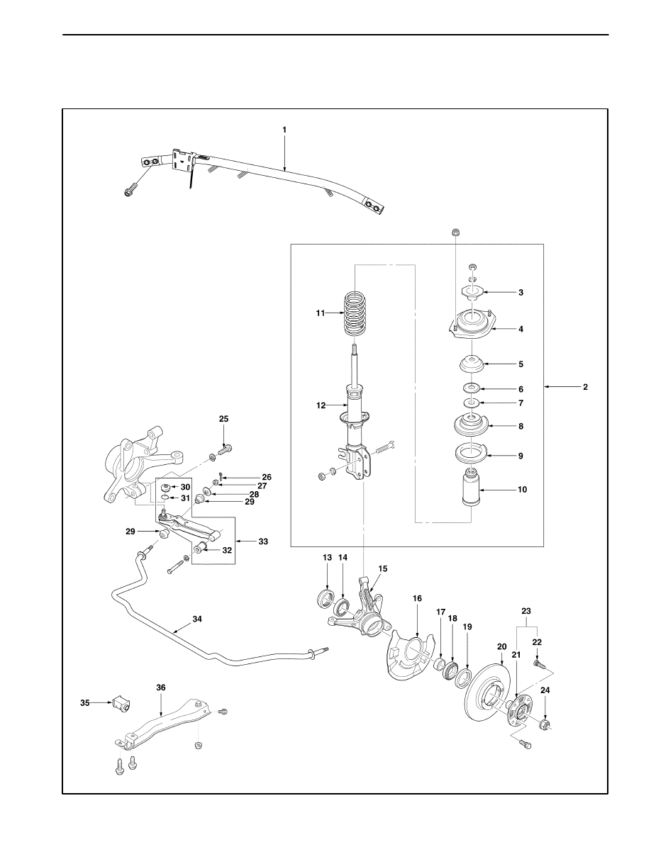
COMPONENT LOCATOR
FRONT SUSPENSION
D16B401A

2C – 4 FRONT SUSPENSION
DAEWOO M-150 BL2
1. Strut Bar
2. Front Suspension Strut Assembly
3. Strut Inner Support
4. Strut Mount Assembly
5. Strut Mount Seat
6. Strut Bearing Seat
7. Strut Bearing
8. Coil Spring Upper Seat
9. Coil Spring Seat
10. Bumper Stopper
11. Coil Spring
12. Strut
13. Inner Bearing Oil Seal
14. Inner Hub Bearing
15. Steering Knuckle
16. Dust Cover
17. Hub Bearing Spacer
18. Outer Hub Bearing
19. Outer Bearing Oil Seal
20. Rotor
21. Wheel Hub
22. Hub Bolt
23. Hub Assembly
24. Drive Axle–to–Hub Caulking Nut
25. Control Arm Ball Stud Bolt
26. Cotter Pin
27. Castellated Nut
28. Washer
29. Stabilizer Shaft Bushing
30. Control Arm Dust Seal
31. Clip
32. Control Arm Bushing
33. Control Arm Assembly
34. Stabilizer Shaft
35. Stabilizer Shaft Mount
36. Front Under Longitudinal Frame

FRONT SUSPENSION 2C – 5
DAEWOO M-150 BL2
DIAGNOSTIC INFORMATION AND PROCEDURES
STRUT DAMPENER
A strut dampener is basically a shock absorber. However, strut dampeners are easier to extend and retract by hand
than are shock absorbers. Strut dampeners are used only on the front in most vehicles, including this vehicle. Shock
absorbers are used on the rear wheels.
ÁÁÁÁÁÁÁÁÁÁ
ÁÁÁÁÁÁÁÁÁÁ
Condition
ÁÁÁÁÁÁÁÁÁÁÁÁÁ
ÁÁÁÁÁÁÁÁÁÁÁÁÁ
Probable cause
ÁÁÁÁÁÁÁÁÁÁÁÁÁÁ
ÁÁÁÁÁÁÁÁÁÁÁÁÁÁ
Correction
Struts Seem Weak
D
Improper tire pressures.
D
Adjust the tire pressures to the speci-
fications on the tire placard.
D
Abnormal load conditions.
D
Consult with the owner to confirm the
owner’s understanding of normal load
conditions.
D
Improper compression and rebound
effectiveness of the strut dampener.
D
Quickly push down and then lift up on
the corner of the bumper nearest the
strut dampener being tested.
D
Compare the compression and re-
bound with those of a similar vehicle
that has an acceptable ride quality.
D
Replace the strut dampener, if need-
ed.
Struts are Noisy
D
Loose or damaged mountings.
D
Tighten the strut dampener.
D
Replace the strut dampener if need-
ed.
D
Improper compression and rebound
effectiveness of the strut dampener.
D
Quickly push down and then lift up on
the corner of the bumper nearest the
strut dampener being tested.
D
Compare the compression and re-
bound with those of a similar vehicle
that has an acceptable ride quality.
D
Replace the strut dampener, if need-
ed.
Leaks
D
A slight trace of fluid.
D
The strut dampener is OK.
D
Leaks of the seal cover on the fully
extended strut.
D
Replace the strut dampener.
D
Excessive leaks of fluid on the strut
dampener.
D
Replace the strut dampener.
BALL JOINT AND KNUCKLE
Ball Joint Inspection
1. Raise the front of the vehicle to allow the front sus-
pension to hang free.
2. Grasp the tire at the top and the bottom.
3. Move the top of the tire in an in-and-out motion.
4. Look for any horizontal movement of the knuckle rela-
tive to the control arm.
5. Control arms assembly must be replaced if the follow-
ing conditions exist:
D
The joint is loose.
D
The ball seal is cut.
D
The ball stud is disconnected from the knuckle.
D
The ball stud is loose at the knuckle.
D
The ball stud can be twisted in its socket with finger
pressure.
Ball Stud Inspection
Make sure to check the tightness of the ball stud in the
knuckle boss during each inspection of the ball joint.
One way to inspect the ball stud for wear is to shake the
wheel and feel for movement of the stud end or the cas-
tellated nut at the knuckle boss.
Another way to inspect the ball stud for wear is to check
the fastener torque at the castellated nut. A loose nut can
indicate a stressed stud or a hole in the knuckle boss.
Worn or damaged ball joints and knuckles must be re-
placed.
2C – 6 FRONT SUSPENSION
DAEWOO M-150 BL2
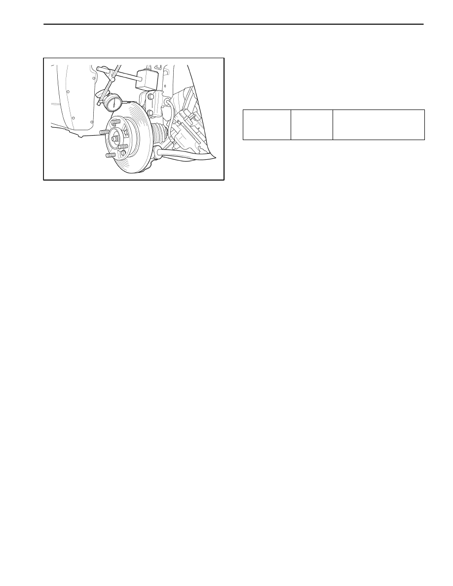
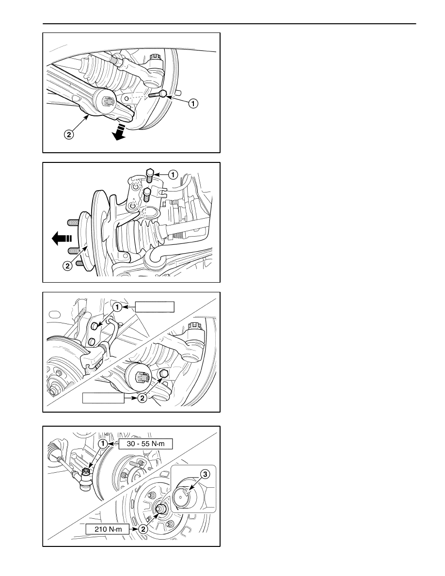
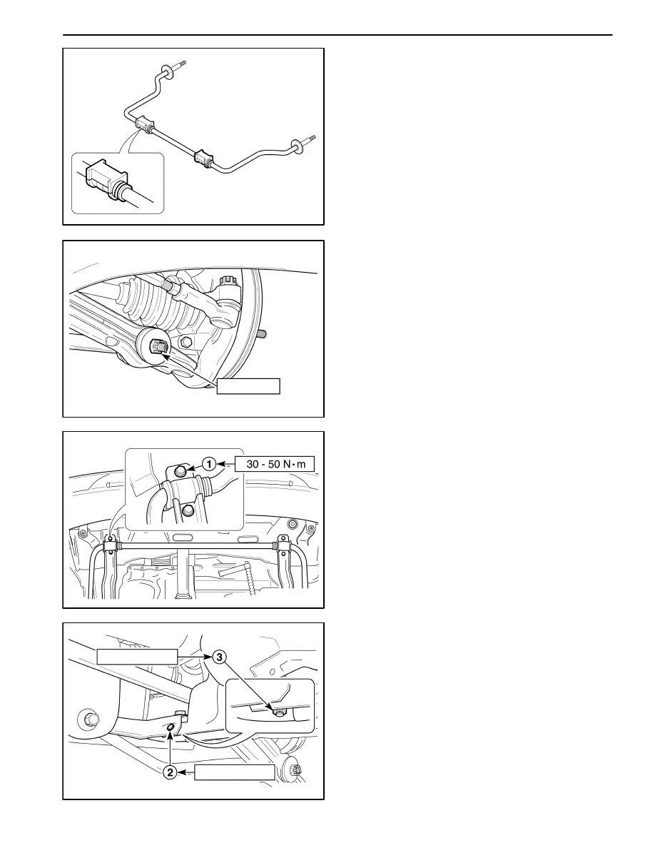
FRONT WHEEL BEARING
Bearing Axial End Play Inspection
D107B303
1. Lift and suitably support the vehicle.
2. Inspect the end play of the bearing.
3. If excessive play is defeeted, free shoes from the disc
or remove the calipers.
4. Check the standard torque of the drive nut (spec. :
210 N
S
m (155 lb-ft)).
5. Check the bearing end play according to the following
method.
D
Place a dial guage against the disc surface, grasp
the disc.
D
Using a push–pull movement, note gage readings.
Specification
0.130mm
or less
(0.005 in)
Standard tighting torque
of drive shaft nut :
210 N
S
m (155 lb-ft)
6. If the axial end play of the front wheel bearing exceed
0.130mm torque the drive shaft nut successively
(Max. allowance : 240 N
S
m (177 lb-ft))
7. Check the axial end play again.
8. If the axial end play is above spec., replace the front
wheel bearing.
FRONT SUSPENSION 2C – 7
DAEWOO M-150 BL2
REPAIR INSTRUCTIONS
ON–VEHICLE SERVICE
D16B501A
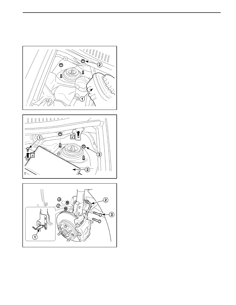
STRUT ASSEMBLY
Removal Procedure
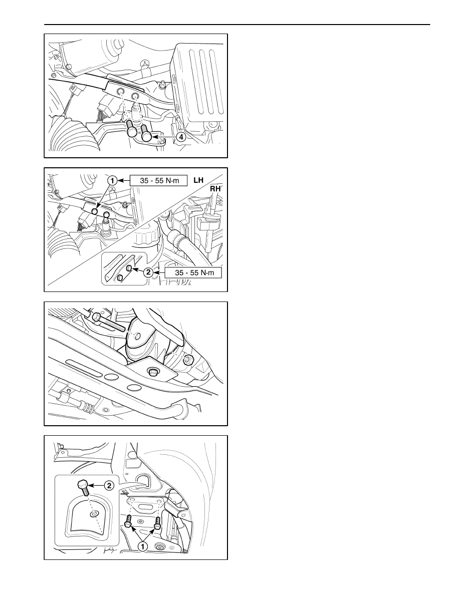
1. Open the hood.
2. Remove the top of the strut assembly at passenger
seat side.
D
For vehicle with power steering, remove the power
steering fluid reservoir (1).
D
Remove the nuts (2).
D16B502A
3. Remove the top of the strut assembly at driver side.
D
Remove the bolt and the fuse box (1, 2).
D
Remove the nuts (3).
D106B503
4. Remove the lower of the strut assembly.
D
Raise and suitably support the vehicle.
D
Remove the wheel. Refer to Section 2E, Tires and
Wheels.
D
Remove the ABS front speed sensor electrical wire
from the bracket, if applicable (1).
D
Disconnect the brake hose from the bracket (2).
D
Remove the strut bracket bolts (3).
5. Remove the strut bracket assembly from the vehicle.
2C – 8 FRONT SUSPENSION
DAEWOO M-150 BL2
D16B504A
70–90 N
S
m
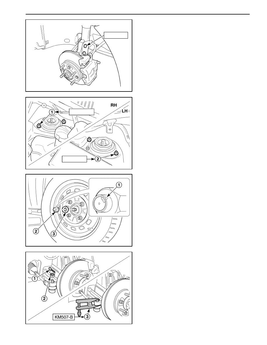
Installation Procedure
1. Install the strut assembly to the vehicle with the strut
assembly–to–strut bracket bolts.
Tighten
Tighten the strut assembly–to–strut bracket bolts to
70–90 N
S
m (52–66 lb-ft).
2. Connect the brake hose to the bracket.
3. Install the ABS front speed sensor electrical wire to
the bracket, if applicable.
D16B505A
18–28 N
S
m
18–28 N
S
m
4. Install the wheel. Refer to Section 2E, Tires and
Wheels.
5. Lower the vehicle.
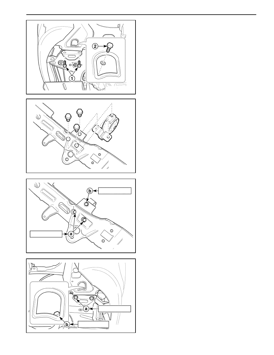
6. Install the nuts.
D
Install the nuts at passenger side (1).
Tighten
Tighten the nuts to 18–28 N
S
m (13–21 lb-ft).
D
Install the nuts at driver side (2).
Tighten
Tighten the nuts to 18–28 N
S
m (13–21 lb-ft).
7. Install the power steering fluid reservoir.
8. Install the fuse box and bolt.
D106B506
KNUCKLE ASSEMBLY
Tools Required
KM 507–B Ball Joint Remover
Removal Procedure
1. Remove the caulking nut.
D
Straighten the bent flange caulking nut (1).
D
Remove the caulking nut (2).
D
Remove the washer (3).
2. Remove the wheel. Refer to Section 2E, Tires and
Wheels.
D105B501
3. Separate the tie rod end from the knuckle assembly.
D
Remove the cotter pin (1).
D
Remove the castellated nut (2).
D
Install the ball joint remover KM 507–B.
D
Separate the tie rod end from the knuckle assem-
bly using a ball joint remover KM 507–B (3).
FRONT SUSPENSION 2C – 9
DAEWOO M-150 BL2
D106B507
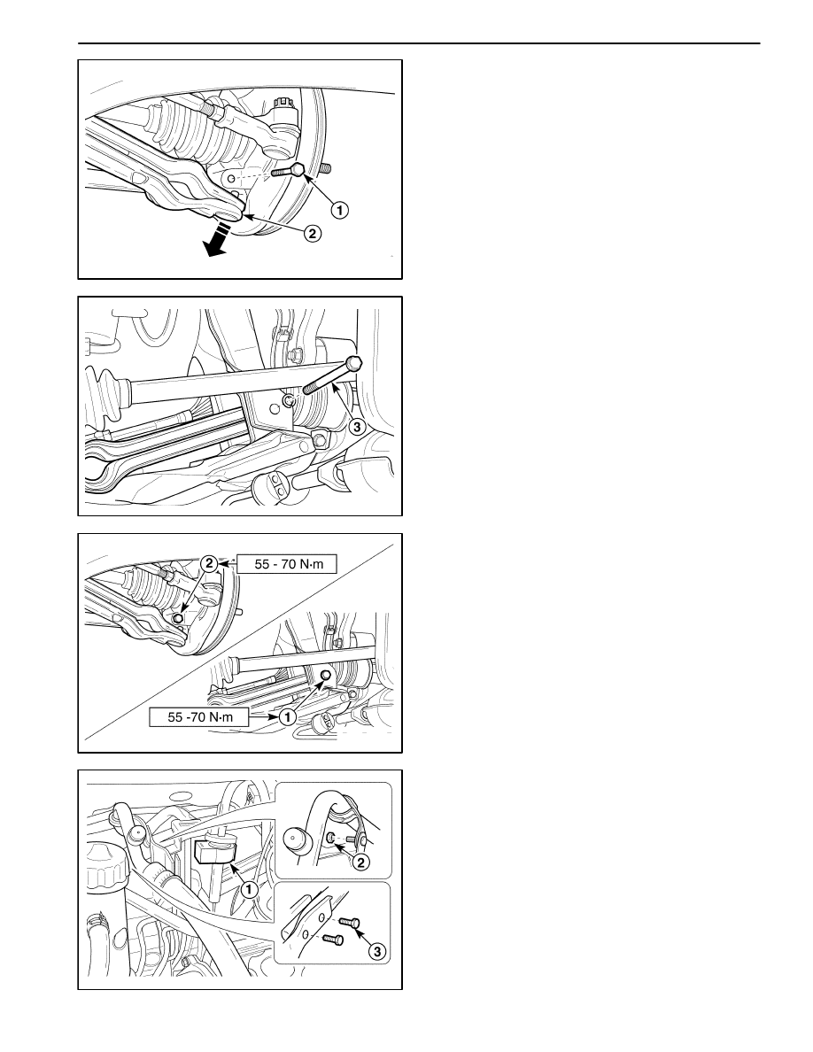
4. Remove the control arm from the knuckle assembly.
D
Remove the stud bolt (1).
D
Separate the control arm from the knuckle assem-
bly (2).
D106B508
5. Remove the brake caliper from the knuckle assembly.
Refer to Section 4D, Front Disc Brakes.
6. Remove the ABS wheel speed sensor from the
knuckle assembly, if applicable. Refer to Section 4F,
Anti–lock Brake System.
7. Remove the steering knuckle assembly from the ve-
hicle.
D
Remove the strut bracket bolts (1).
D
Separate the knuckle assembly from the drive
shaft by pulling the steering knuckle assembly (2).
D16B509A
70–90 N
S
m
50–70 N
S
m
Installation Procedure
1. Install in the reverse order of removal.
2. Install the steering knuckle assembly in the vehicle
with strut bracket bolts (1).
Tighten
Tighten the strut bracket bolts to 70–90 N
S
m (52–66
lb-ft).
3. Install the brake caliper from the knuckle assembly.
4. Install the control arm into the knuckle assembly with
the stud bolt (2).
Tighten
Tighten the stud bolt to 50–70 N
S
m (36–52 lb-ft).
D16B510B
5. Install the tie rod end to the knuckle assembly.
6. Install the tie rod end–to–knuckle castellated nut (1)
and the cotter pin.
Tighten
Tighten the castellated nut to 30–55 N
S
m (22–41 lb-
ft).
7. Install the caulking nut (2).
D
Bend the caulking nut flange (3).
Tighten
Tighten the caulking nut to 210 N
S
m (155 lb-ft).
2C – 10 FRONT SUSPENSION
DAEWOO M-150 BL2
D106B511
FRONT LONGITUDINAL FRAME AND
STABILIZER SHAFT
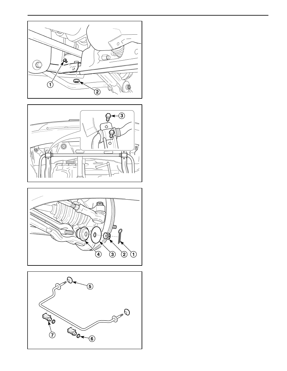
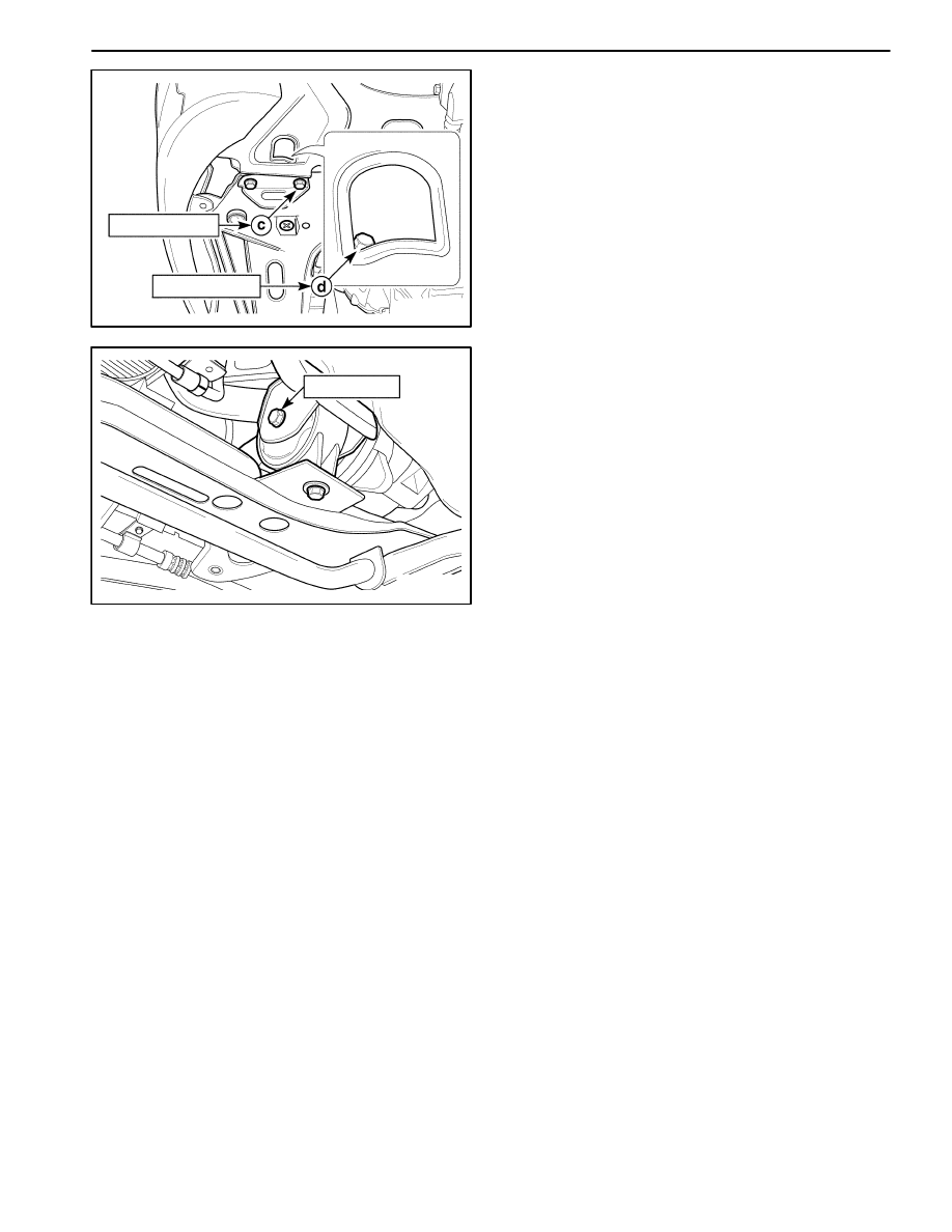
Removal Procedure
1. Removed the front under longitudinal frame.
D
Raise and suitably support the vehicle.
D
Remove the front wheel. Refer to Section 2E, Tires
and Wheels.
D
Remove the transaxle under cover. Refer to Sec-
tion 5B, Manual Transaxle.
D
Remove the front under longitudinal frame bolt (1).
D
Remove the front under longitudinal frame nut (2).
D16B512A
D
Remove the stabilizer shaft mounting bolts (3).
D
Remove the front under longitudinal frame.
D106B513
2. Remove the stabilizer shaft from the vehicle.
D
Remove the cotter pin (1).
D
Remove the castellated nut (2).
D
Remove the washer (3).
D
Remove the rear bushing with separating the sta-
bilizer shaft from the control arm (4).
D16B514A
D
Remove the bushing (5).
D
Remove the wire clamps (6).
D
Remove the mountings (7).
FRONT SUSPENSION 2C – 11
DAEWOO M-150 BL2
D16B515A
Installation Procedure
1. Install in the reverse order of removal.
Important: When installing the mountings, position the
opened mountings forward.
D16B516A
40–50 N
S
m
2. Install the stabilizer shaft to the vehicle.
D
Install the castellated nut.
Tighten
Tighten the stabilizer shaft–to–body castellated nut to
40–50 N
S
m (30–36 lb-ft).
D
Install the cotter pin.
D16B517C
3. Install the front under longitudinal frame.
D
Install the stabilizer shaft mounting bolts (1).
Tighten
Tighten the mounting bolts to 30–50 N
S
m (22–36 lb-
ft).
D16B518B
65 – 80 N
S
m
10 – 14 N
S
m
D
Install the front under longitudinal frame bolt (2).
Tighten
Tighten to bolt to 10–14 N
S
m (89–124 lb-in).
D
Install the front under longitudinal frame nut (3).
Tighten
Tighten to nut to 65–80 N
S
m (48–59 lb-ft).
2C – 12 FRONT SUSPENSION
DAEWOO M-150 BL2
D106B519
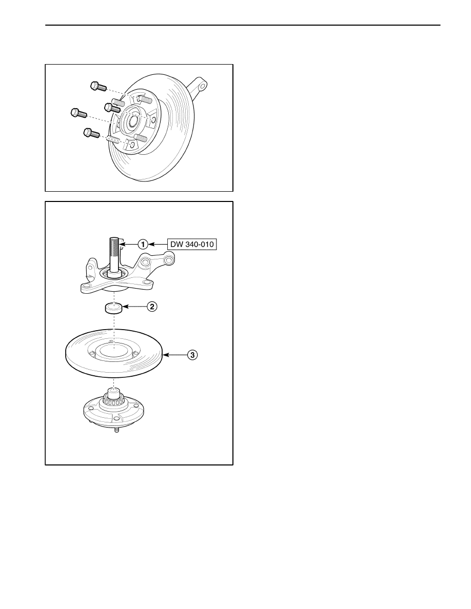
CONTROL ARM
Removal Procedure
1. Remove the stabilizer shaft. Refer to “Front Longitu-
dinal Frame and Stabilizer Shaft” in this section.
2. Remove the control arm.
D
Remove the stud bolt (1).
D
Separate the control arm from the knuckle assem-
bly using a lever (2).
D106B520
D
Remove the bolt (3).
D
Remove the control arm.
D16B521B
Installation Procedure
1. Install the control arm onto the vehicle.
D
Install the control arm bolt (1).
Tighten
Tighten the control arm bolt to 55–70 N
S
m (41–52 lb-
ft).
D
Install the control arm to the knuckle assembly.
D
Install the stud bolt (2).
Tighten
Tighten the stud bolt to 50–70 N
S
m (36–52 lb-ft).
2. Install the stabilizer shaft.
D10B522A
STRUT BAR
Removal Procedure
1. Open the hood.
2. Remove the strut bar from the vehicle.
D
Remove the purge control valve (1).
D
Remove the A/C low pressure pipe bracket–to–
strut bar nut (2).
D
Remove the strut bar bolts at passenger side (3).
FRONT SUSPENSION 2C – 13
DAEWOO M-150 BL2
D106B523
D
Remove the strut bar bolts at driver side (4).
Important: When removing the bolts using the tool,
do not contact the battery terminal.
D
Remove the strut bar at passenger side
D16B524B
Installation Procedure
1. Install the strut bar to the vehicle.
D
Install the strut bar at passenger side.
D
Install the strut bar bolts at driver side (1).
Important: When installing the bolts using the tool, do
not contact the battery terminal.
D
Install the strut bar bolts at passenger side (2).
D
Install the A/C low pressure pipe bracket–to–strut
bar nut.
Tighten
Tighten the strut bar bolts to 35–55 N
S
m (25–41 lb-ft).
D
Install the purge control valve to the strut bar.
D106B525
CROSSMEMBER
Removal Procedure
1. Remove the transaxle under cover. Refer to Section
5B, Five–Speed Manual Transaxle.
2. Remove the front under longitudinal frame. Refer to
“Stabilizer Shaft” in this section.
3. Remove the damping bush bolt and nut.
D106B526
4. Disconnect the power steering pressure line from the
crossmember. Refer to Section 6B, Power Steering
Pump.
5. Remove the crossmember from the vehicle.
D
Place support jack under the crossmember.
D
Remove the bumper fascia screws.
D
Remove the rear bolts (1).
D
Remove the side bolts (2).
D
Lower the support jack and remove the crossmem-
ber from the vehicle.
2C – 14 FRONT SUSPENSION
DAEWOO M-150 BL2
D106B527
D106B528
6. Remove the front damping bush bolts and damping
bush from the crossmember.
D16B529A
35–41 N
S
m
45–55 N
S
m
Installation Procedure
1. Install in the reverse order of removal.
2. Install the front damping bush to the crossmember.
Tighten
D
Tighten the bolts to 45–55 N
S
m (33–41 lb-ft).
a. Front damping bush bolt.
D
Tighten the bolt to 35–41 N
S
m (25–30 lb-ft).
b. Front damping bush bolt.
D16B530A
17–27 N
S
m
17–27 N
S
m
3. Install the crossmember to the vehicle with the bolts.
Tighten
Tighten the bolts to 17–27 N
S
m (13–20 lb-ft).
a. Crossmember right rear bolt.
b. Crossmember right side bolt.
FRONT SUSPENSION 2C – 15
DAEWOO M-150 BL2
D16B531A
17–27 N
S
m
17–27 N
S
m
c. Crossmember left rear bolt.
d. Crossmember leftt side bolt.
D16B532A
68–83 N
S
m
4. Install the front damping bush to the vehicle.
Tighten
Tighten the front damping bush bolt and nut to 68–83
N
S
m (51–61 lb-ft).
5. Install the front under longitudinal frame. Refer to
“Stabilizer Shaft” in this section.
2C – 16 FRONT SUSPENSION
DAEWOO M-150 BL2
UNIT REPAIR
D106B701
HUB BEARING AND KNUCKLE
Tools Required
DW 220–020A–01 Differential Bearing Puller.
DW 220–020A–04 Differential Bearing Plate Adapter.
DW 340–010
Front Wheel Hub Remover.
DW 340–020
Front Wheel Bearing Race Installer.
DW 340–030
Front Wheel Bearing Installer.
09940–71430
Front Spring Compressor.
Disassembly Procedure
1. Remove the steering knuckle assembly. Refer to
“Knuckle Assembly” in this section.
2. Remove the bolts from the wheel hub.
D106B702
3. Remove the wheel hub from the knuckle assembly
using the front wheel hub remover DW 340–010.
D
Remove the wheel hub using the front wheel hub
remover DW 340–010 (1).
D
Remove the bearing spacer (2).
D
Remove the brake rotor (3).
FRONT SUSPENSION 2C – 17
DAEWOO M-150 BL2
D16B703A
D
Remove the wheel bearing from the wheel hub us-
ing the differential bearing puller DW 220–020A–01
and differential bearing plate adapter DW 220–
020A–04 (4).
D106B704
D
Remove the oil seal from the wheel hub (5).
Important: Do not use removed oil seal.
D106B705
4. Remove the steering knuckle assembly.
D
Remove the oil seal (1).
Important: Do not use removed oil seal.
D
Remove the wheel bearing (2).
D106B706
D
Remove the outer bearing race (3).
2C – 18 FRONT SUSPENSION
DAEWOO M-150 BL2
D106B707
D
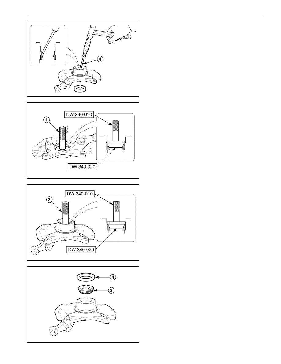
Remove the inner bearing race (4).
D106B708
Assembly Procedure
1. Assemble the steering knuckle assembly.
D
Assemble the inner bearing race using the front
wheel hub remover DW 340–010 and the front
bearing race installer DW 340–020 (1).
D106B709
D
Assemble the outer bearing race using the front
wheel hub remover DW 340–010 and the front
wheel bearing race installer DW 340–020 (2).
D106B710
D
Assemble the outer wheel bearing (3).
D
Assemble the outer wheel bearing oil seal (4).
FRONT SUSPENSION 2C – 19
DAEWOO M-150 BL2
D106B711
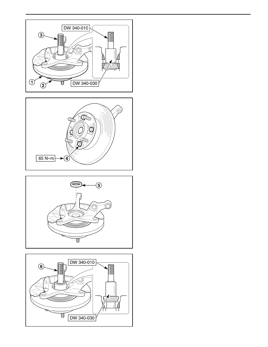
2. Install the wheel hub to steering knuckle assembly.
D
Install the brake rotor (1).
D
Install the wheel hub to the steering knuckle as-
sembly temporary (2).
D
Press the outer wheel bearing into the wheel hub
using the front wheel hub remover DW 340–010
and the front wheel bearing installer DW 340–030
(3).
D16B712A
D
Tighten the bolts (4).
Tighten
Tighten the bolt to 65 N
S
m (48 lb-ft).
D106B713
D
Install the bearing spacer (5).
D106B714
D
Press the inner wheel bearing into the wheel hub
using the front wheel hub remover DW 340–010
and the front wheel bearing installer DW 340–030
(6).
2C – 20 FRONT SUSPENSION
DAEWOO M-150 BL2
D106B715
D
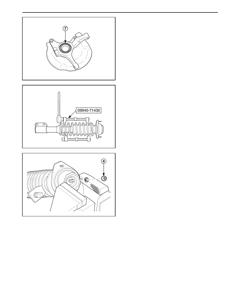
Install the inner wheel bearing oil seal (7).
3. Install the steering knuckle assembly.
Refer to “Knuckle Assembly” in this section.
D106B716
FRONT STRUT (INCLUDING COIL
SPRING)
Tools Required
09940–71430 Front Spring Compressor.
Disassembly Procedure
1. Remove the strut assembly. Refer to “Strut Assem-
bly” in this section.
2. Compress the front spring with the front spring com-
pressor 09940–71430.
Caution: During compressing spring, do not make
spring end point to operator or dangerous direc-
tion.
D106B717
3. Fix the strut support using the bench vise and remove
the strut nut.
a. Strut nut.
FRONT SUSPENSION 2C – 21
DAEWOO M-150 BL2
D16B718A
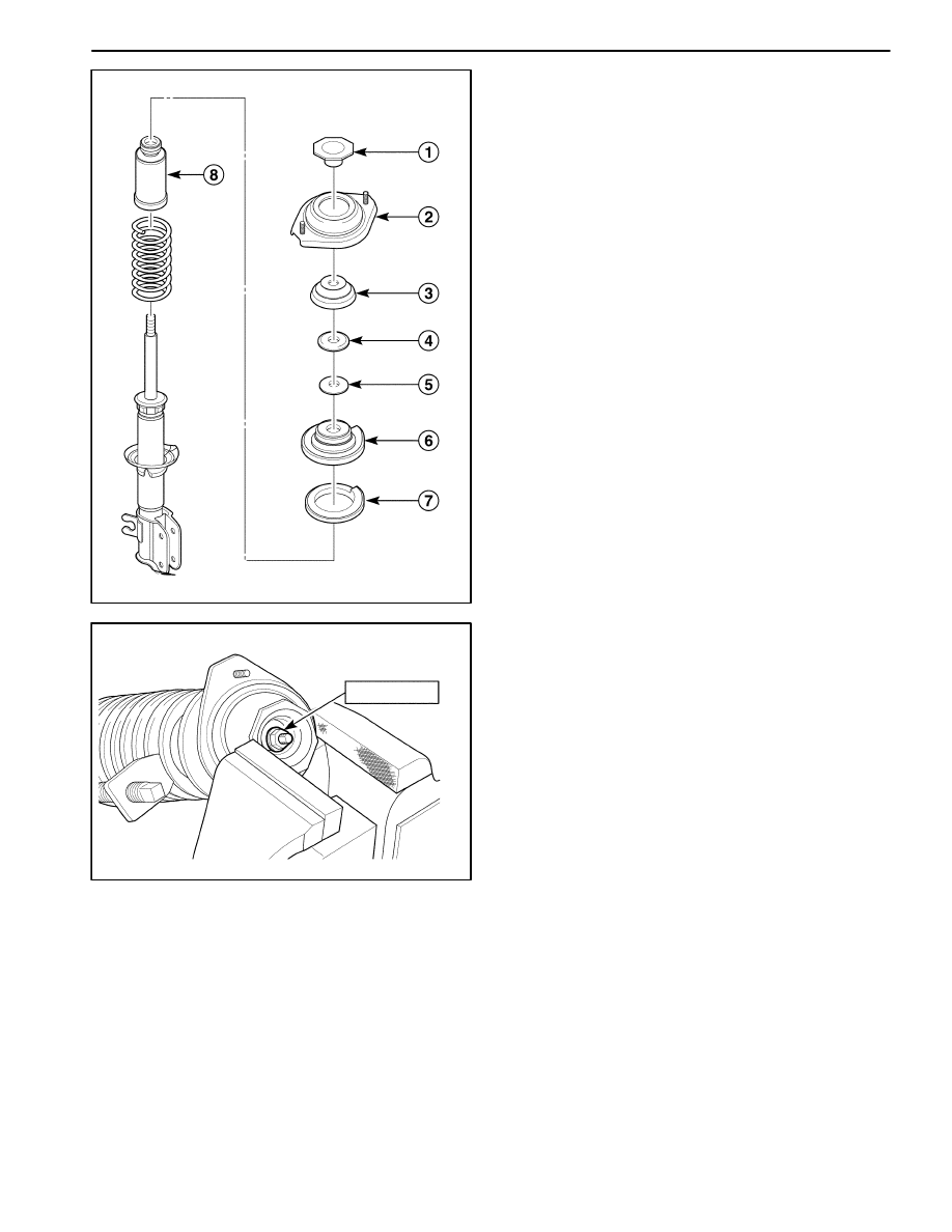
4. Remove the coil spring.
D
Remove the strut inner support (1).
D
Remove the strut mount assembly (2).
D
Remove the strut mount seat (3).
D
Remove the strut bearing seat (4).
D
Remove the strut bearing (5).
D
Remove the coil spring upper seat (6).
D
Remove the coil spring seat (7).
D
Remove the bumper stopper (8).
D16B719A
50–60 N
S
m
Assembly Procedure
1. Install the coil spring, front bumper stopper, coil
spring seat, coil spring upper seat, strut bearing,
bearing seat, mounting seat, mount assembly and in-
ner support to the strut.
2. Tighten the strut nut.
D
Fix the strut support using the bench vise.
D
Tighten the nut.
Tighten
Tighten the strut nut to 50–60 N
S
m (36–44 lb-ft).
2C – 22 FRONT SUSPENSION
DAEWOO M-150 BL2
D106B720
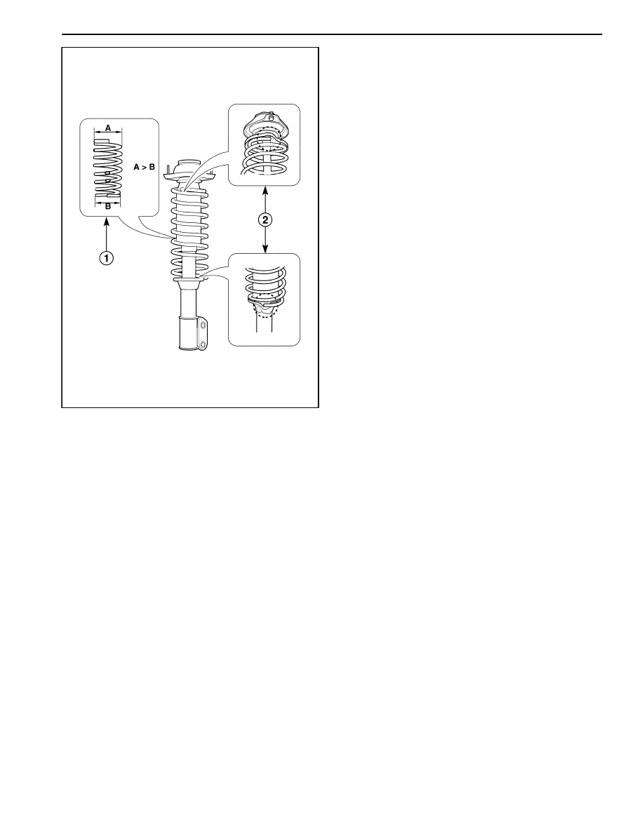
3. Inspect the installation of coil spring (1, 2).
4. Install the strut assembly. Refer to “Strut Assembly”
in this section.

FRONT SUSPENSION 2C – 23
DAEWOO M-150 BL2
SPECIFICATIONS
GENERAL SPECIFICATIONS
ÁÁÁÁÁÁÁÁÁÁÁÁÁÁÁÁÁ
ÁÁÁÁÁÁÁÁÁÁÁÁÁÁÁÁÁ
Application
ÁÁÁÁÁÁ
ÁÁÁÁÁÁ
Unit
ÁÁÁÁÁÁÁÁÁÁÁÁÁÁ
ÁÁÁÁÁÁÁÁÁÁÁÁÁÁ
Description
ÁÁÁÁÁÁÁÁÁÁÁÁÁÁÁÁÁ
ÁÁÁÁÁÁÁÁÁÁÁÁÁÁÁÁÁ
Suspension Type
ÁÁÁÁÁÁ
ÁÁÁÁÁÁ
–
ÁÁÁÁÁÁÁÁÁÁÁÁÁÁ
ÁÁÁÁÁÁÁÁÁÁÁÁÁÁ
Mcpherson (Strut)
ÁÁÁÁÁÁÁÁ
ÁÁÁÁÁÁÁÁ
ÁÁÁÁÁÁÁÁÁÁ
ÁÁÁÁÁÁÁÁÁÁ
Maximum Length
ÁÁÁÁÁÁ
ÁÁÁÁÁÁ
mm (in.)
ÁÁÁÁÁÁÁÁÁÁÁÁÁÁ
ÁÁÁÁÁÁÁÁÁÁÁÁÁÁ
475–481 (18.7–18.94)
ÁÁÁÁÁÁÁÁ
ÁÁÁÁÁÁÁÁ
Shock Absorber
ÁÁÁÁÁÁÁÁÁÁ
ÁÁÁÁÁÁÁÁÁÁ
Minimum Length
ÁÁÁÁÁÁ
ÁÁÁÁÁÁ
mm (in.)
ÁÁÁÁÁÁÁÁÁÁÁÁÁÁ
ÁÁÁÁÁÁÁÁÁÁÁÁÁÁ
321–327 (12.64–12.87)
ÁÁÁÁÁÁÁÁ
ÁÁÁÁÁÁÁÁ
ÁÁÁÁÁÁÁÁÁÁ
ÁÁÁÁÁÁÁÁÁÁ
Stroke
ÁÁÁÁÁÁ
ÁÁÁÁÁÁ
mm (in.)
ÁÁÁÁÁÁÁÁÁÁÁÁÁÁ
ÁÁÁÁÁÁÁÁÁÁÁÁÁÁ
154 (6.06)
ÁÁÁÁÁÁÁÁÁÁÁÁÁÁÁÁÁ
ÁÁÁÁÁÁÁÁÁÁÁÁÁÁÁÁÁ
ÁÁÁÁÁÁÁÁÁÁÁÁÁÁÁÁÁ
Stabilizer Shaft Diammeter
ÁÁÁÁÁÁ
ÁÁÁÁÁÁ
ÁÁÁÁÁÁ
mm (in.)
ÁÁÁÁÁÁÁÁÁÁÁÁÁÁ
ÁÁÁÁÁÁÁÁÁÁÁÁÁÁ
ÁÁÁÁÁÁÁÁÁÁÁÁÁÁ
24 (0.94)
ÁÁÁÁÁÁÁÁÁÁÁÁÁÁÁÁÁ
ÁÁÁÁÁÁÁÁÁÁÁÁÁÁÁÁÁ
Coil Spring Height (No Load)
ÁÁÁÁÁÁ
ÁÁÁÁÁÁ
mm (in.)
ÁÁÁÁÁÁÁÁÁÁÁÁÁÁ
ÁÁÁÁÁÁÁÁÁÁÁÁÁÁ
374 (14.72 )
ÁÁÁÁÁÁÁÁÁÁÁÁÁÁÁÁÁ
ÁÁÁÁÁÁÁÁÁÁÁÁÁÁÁÁÁ
Grease Type (Front Wheel Bearing and Hub)
ÁÁÁÁÁÁ
ÁÁÁÁÁÁ
–
ÁÁÁÁÁÁÁÁÁÁÁÁÁÁ
ÁÁÁÁÁÁÁÁÁÁÁÁÁÁ
M–8143 ANTIF BRG GREASE
FASTENER TIGHTENING SPECIFICATIONS
ÁÁÁÁÁÁÁÁÁÁÁÁÁÁÁÁÁÁ
ÁÁÁÁÁÁÁÁÁÁÁÁÁÁÁÁÁÁ
Application
ÁÁÁÁÁÁÁ
ÁÁÁÁÁÁÁ
N
S
m
ÁÁÁÁÁÁ
ÁÁÁÁÁÁ
Lb-Ft
ÁÁÁÁÁÁÁ
ÁÁÁÁÁÁÁ
Lb-In
ÁÁÁÁÁÁÁÁÁÁÁÁÁÁÁÁÁÁ
ÁÁÁÁÁÁÁÁÁÁÁÁÁÁÁÁÁÁ
Strut Assembly–to–Body Nuts
ÁÁÁÁÁÁÁ
ÁÁÁÁÁÁÁ
18 – 28
ÁÁÁÁÁÁ
ÁÁÁÁÁÁ
13 – 21
ÁÁÁÁÁÁÁ
ÁÁÁÁÁÁÁ
–
ÁÁÁÁÁÁÁÁÁÁÁÁÁÁÁÁÁÁ
ÁÁÁÁÁÁÁÁÁÁÁÁÁÁÁÁÁÁ
Strut Closure Nut
ÁÁÁÁÁÁÁ
ÁÁÁÁÁÁÁ
50 – 60
ÁÁÁÁÁÁ
ÁÁÁÁÁÁ
36 – 44
ÁÁÁÁÁÁÁ
ÁÁÁÁÁÁÁ
–
ÁÁÁÁÁÁÁÁÁÁÁÁÁÁÁÁÁÁ
ÁÁÁÁÁÁÁÁÁÁÁÁÁÁÁÁÁÁ
Strut Assembly–to–Knuckle Bolts
ÁÁÁÁÁÁÁ
ÁÁÁÁÁÁÁ
70 – 90
ÁÁÁÁÁÁ
ÁÁÁÁÁÁ
52 – 66
ÁÁÁÁÁÁÁ
ÁÁÁÁÁÁÁ
–
ÁÁÁÁÁÁÁÁÁÁÁÁÁÁÁÁÁÁ
ÁÁÁÁÁÁÁÁÁÁÁÁÁÁÁÁÁÁ
Control Arm Mounting Bolt
ÁÁÁÁÁÁÁ
ÁÁÁÁÁÁÁ
55 – 70
ÁÁÁÁÁÁ
ÁÁÁÁÁÁ
41 – 52
ÁÁÁÁÁÁÁ
ÁÁÁÁÁÁÁ
–
ÁÁÁÁÁÁÁÁÁÁÁÁÁÁÁÁÁÁ
ÁÁÁÁÁÁÁÁÁÁÁÁÁÁÁÁÁÁ
ÁÁÁÁÁÁÁÁÁÁÁÁÁÁÁÁÁÁ
Control Arm Ball Stud Bolt
ÁÁÁÁÁÁÁ
ÁÁÁÁÁÁÁ
ÁÁÁÁÁÁÁ
50 – 70
ÁÁÁÁÁÁ
ÁÁÁÁÁÁ
ÁÁÁÁÁÁ
36 – 52
ÁÁÁÁÁÁÁ
ÁÁÁÁÁÁÁ
ÁÁÁÁÁÁÁ
–
ÁÁÁÁÁÁÁÁÁÁÁÁÁÁÁÁÁÁ
ÁÁÁÁÁÁÁÁÁÁÁÁÁÁÁÁÁÁ
Stabilizer Shaft Castellated Nut
ÁÁÁÁÁÁÁ
ÁÁÁÁÁÁÁ
40 – 50
ÁÁÁÁÁÁ
ÁÁÁÁÁÁ
30 – 36
ÁÁÁÁÁÁÁ
ÁÁÁÁÁÁÁ
–
ÁÁÁÁÁÁÁÁÁÁÁÁÁÁÁÁÁÁ
ÁÁÁÁÁÁÁÁÁÁÁÁÁÁÁÁÁÁ
Stabilizer Shaft Mounting Bolt
ÁÁÁÁÁÁÁ
ÁÁÁÁÁÁÁ
30 – 50
ÁÁÁÁÁÁ
ÁÁÁÁÁÁ
22 – 36
ÁÁÁÁÁÁÁ
ÁÁÁÁÁÁÁ
–
ÁÁÁÁÁÁÁÁÁÁÁÁÁÁÁÁÁÁ
ÁÁÁÁÁÁÁÁÁÁÁÁÁÁÁÁÁÁ
Front Under Longitudinal Frame Bolts
ÁÁÁÁÁÁÁ
ÁÁÁÁÁÁÁ
10 – 14
ÁÁÁÁÁÁ
ÁÁÁÁÁÁ
–
ÁÁÁÁÁÁÁ
ÁÁÁÁÁÁÁ
89 – 124
ÁÁÁÁÁÁÁÁÁÁÁÁÁÁÁÁÁÁ
ÁÁÁÁÁÁÁÁÁÁÁÁÁÁÁÁÁÁ
Front Under Longitudinal Frame Nut
ÁÁÁÁÁÁÁ
ÁÁÁÁÁÁÁ
65 – 80
ÁÁÁÁÁÁ
ÁÁÁÁÁÁ
48 – 59
ÁÁÁÁÁÁÁ
ÁÁÁÁÁÁÁ
–
ÁÁÁÁÁÁÁÁÁÁÁÁÁÁÁÁÁÁ
ÁÁÁÁÁÁÁÁÁÁÁÁÁÁÁÁÁÁ
Drive Axle–to–Hub Caulking Nut
ÁÁÁÁÁÁÁ
ÁÁÁÁÁÁÁ
210
ÁÁÁÁÁÁ
ÁÁÁÁÁÁ
155
ÁÁÁÁÁÁÁ
ÁÁÁÁÁÁÁ
–
ÁÁÁÁÁÁÁÁÁÁÁÁÁÁÁÁÁÁ
ÁÁÁÁÁÁÁÁÁÁÁÁÁÁÁÁÁÁ
Crossmember Bolt
ÁÁÁÁÁÁÁ
ÁÁÁÁÁÁÁ
17 – 27
ÁÁÁÁÁÁ
ÁÁÁÁÁÁ
13 – 20
ÁÁÁÁÁÁÁ
ÁÁÁÁÁÁÁ
–
ÁÁÁÁÁÁÁÁÁÁÁÁÁÁÁÁÁÁ
ÁÁÁÁÁÁÁÁÁÁÁÁÁÁÁÁÁÁ
ÁÁÁÁÁÁÁÁÁÁÁÁÁÁÁÁÁÁ
Strut Bar Bolts
ÁÁÁÁÁÁÁ
ÁÁÁÁÁÁÁ
ÁÁÁÁÁÁÁ
35 – 55
ÁÁÁÁÁÁ
ÁÁÁÁÁÁ
ÁÁÁÁÁÁ
25 – 41
ÁÁÁÁÁÁÁ
ÁÁÁÁÁÁÁ
ÁÁÁÁÁÁÁ
–
ÁÁÁÁÁÁÁÁÁÁÁÁÁÁÁÁÁÁ
ÁÁÁÁÁÁÁÁÁÁÁÁÁÁÁÁÁÁ
ABS Front Speed Sensor Retaining Bolt
ÁÁÁÁÁÁÁ
ÁÁÁÁÁÁÁ
18 – 28
ÁÁÁÁÁÁ
ÁÁÁÁÁÁ
13 – 21
ÁÁÁÁÁÁÁ
ÁÁÁÁÁÁÁ
–
ÁÁÁÁÁÁÁÁÁÁÁÁÁÁÁÁÁÁ
ÁÁÁÁÁÁÁÁÁÁÁÁÁÁÁÁÁÁ
Wheel Hub–to–Brake Disc Bolt
ÁÁÁÁÁÁÁ
ÁÁÁÁÁÁÁ
55 – 75
ÁÁÁÁÁÁ
ÁÁÁÁÁÁ
41 – 55
ÁÁÁÁÁÁÁ
ÁÁÁÁÁÁÁ
–
2C – 24 FRONT SUSPENSION
DAEWOO M-150 BL2
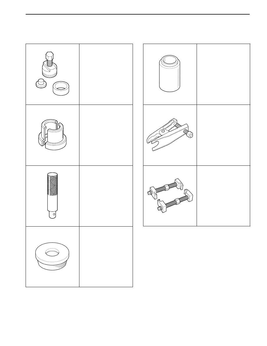
SPECIAL TOOLS AND EQUIPMENT
SPECIAL TOOLS TABLE
D13B112A
DW 220–020A–01
Differential Bearing
Puller
D13B113A
DW 220–020A–04
Differential Bearing
Plate Adapter
D16B101A
DW 340–010
Front Wheel Hub
Remover
D106B102
DW 340–020
Front Wheel Bearing
Race Installer
D106B103
DW 340–030
Front Wheel Bearing
Installer
D105B101
KM 507–B
Ball Joint Remover
D106B104
09940–71430
Front Spring
Compressor
Wyszukiwarka
Podobne podstrony:
26 Front Suspension
FRONT SUSPENSION
09 front suspension
Jag front suspension xk 120,xk 140,xk 150;mk VII,mk VIII,mk IX
26 Front Suspension
26 Front Suspension
26 Front Suspension
Front suspension strut
g3 front suspension
13 Front Suspension
26 Front Suspension
ARTICLE SUSPENSION STRUT FRONT REPLACE INSTALL
ARTICLE SUSPENSION STRUT FRONT DISASSEMBLE REASSEMBLE
11 Front Wheel Suspension Steering
ARTICLE SUSPENSION LOWER CONTROL ARM FRONT SERVICE
więcej podobnych podstron