
2607R–01
–
FRONT SUSPENSION
FRONT SUSPENSION SYSTEM
26–1
1232
Author:
Date:
2004 COROLLA (RM1037U)
FRONT SUSPENSION SYSTEM
PROBLEM SYMPTOMS TABLE
Use the table below to help you find the cause of the problem. The numbers indicate the priority of
the likely cause of the problem. Check each part in order. If necessary, replace these parts.
Symptom
Suspect Area
See page
Bottoming
1. Vehicle (Overloaded)
2. Spring (Weak)
3. Shock absorber (Worn)
–
26–8
26–8
Sways/pitches
1. Tire (Worn or improperly inflated)
2. Stabilizer bar (Bent or broken)
3. Shock absorber (Worn)
28–1
26–19
26–8
Front wheel shimmy
1. Tire (Worn or improperly inflated)
2. Wheel (Out of balance)
3. Shock absorber (Worn)
4. Wheel alignment (Incorrect)
5. Ball joint (Worn)
6. Hub bearing (Worn)
7. Steering linkage (Loose or worn)
28–1
28–1
26–8
26–5
27–3
26–17
30–17
–
Abnormal tire wear
1. Tire (Worn or improperly inflated)
2. Wheel alignment (Incorrect)
3. Shock absorber (Worn)
4. Suspension parts (Worn)
28–1
26–5
27–3
26–8
–
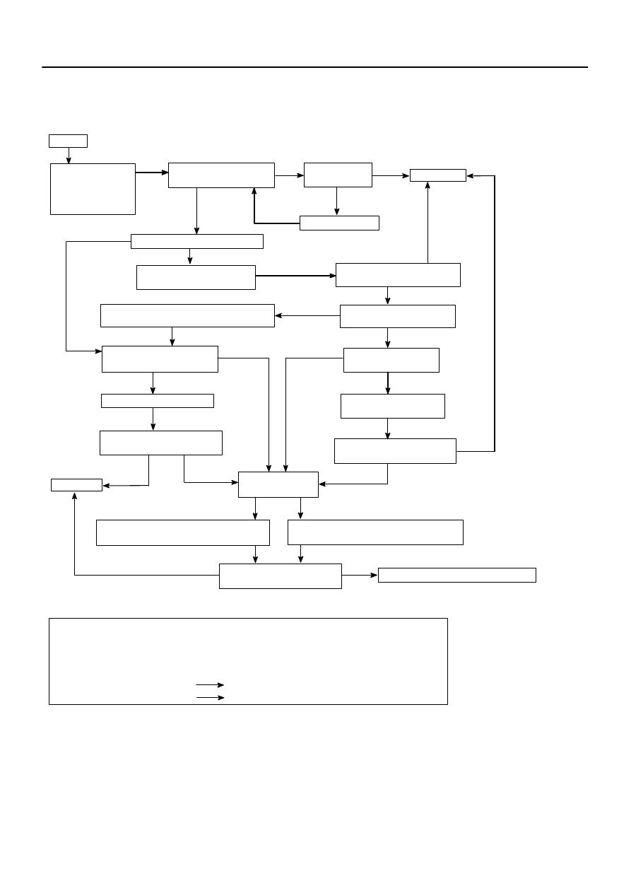
2607S–01
START
Preliminary Check
Tire pressure
Vehicle height
Brake dragging
ROAD TEST
Does the vehicle lead/pull?
Cross switch front tire & wheel
assemblies (left & right).
Does the vehicle lead/pull in
same direction as before?
Check front wheel alignment.
Is it within specification?
Adjust front wheel alignment.
Reverse the front left side
tire and rebalance it.
Does the vehicle
lead/pull to the left?
COMPLETE
Are the tires uni–directional type?
Choose the position of front tire & wheel
assemblies where there is least amount of pull.
Increase left front camber and decrease
right front camber until lead/pull is eliminated.
Increase right front camber and decrease
left front camber until lead/pull is eliminated.
NO
YES
YES
NO
YES
YES
NO
YES
NO
COMPLETE
NO
NO
YES
NO
Is there steering
off center?
Adjust front tie rods.
NO
YES
Is the lead/pull stronger
than before?
NOTICE : Do not exceed 1
°
of cross camber.
Do not exceed adjustment range.
Select a flat road where the vehicle can be driven in a straight line for 100 meters at a constant speed
of 35mph. Please confirm safety and set the steering wheel to its straight position. Drive the vehicle in
a straight line for 100 meters at a constant speed of 35 mph without holding the steering wheel.
(1) The vehicle can keep straight but the steering wheel has some angle.
STEERING OFF CENTER (See page
50–4
)
(2) The vehicle cannot keep straight. STEERING PULL
YES
NO
YES
ROAD TEST
Does the vehicle still lead/pull?
NO
ROAD TEST
Does the vehicle still lead/pull?
ROAD TEST
Does the vehicle still lead/pull?
ROAD TEST
Does the vehicle still lead/pull?
NO
Contact your local retail tire distributor.
YES
*
YES
26–2
–
FRONT SUSPENSION
FRONT SUSPENSION SYSTEM
1233
Author:
Date:
2004 COROLLA (RM1037U)
REPAIR
HINT:
This is a flow chart for vehicle pull.
2607U–01
C95203
N
⋅
m (kgf
⋅
cm, ft
⋅
lbf) : Specified torque
Non–reusable part
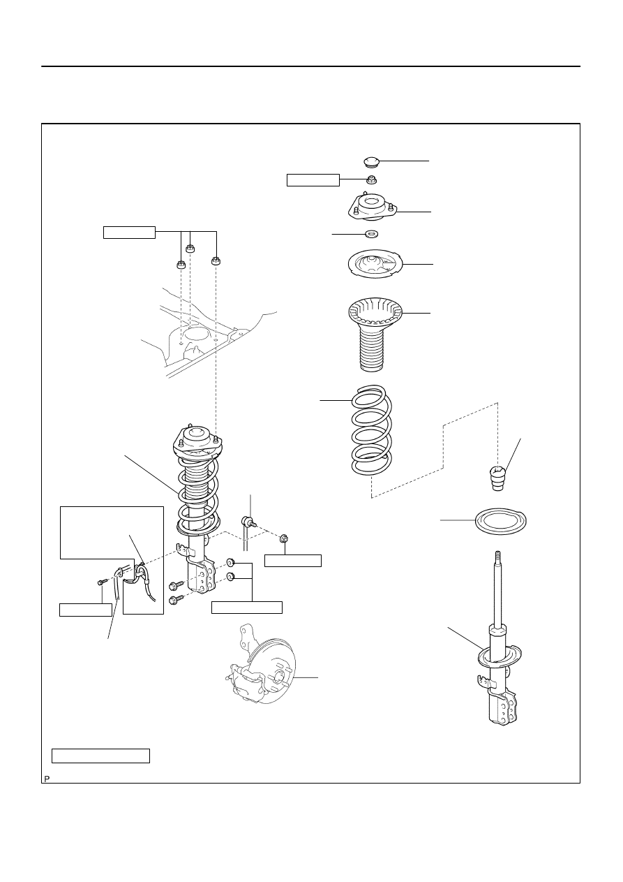
Front Spring
Bumper LH
Front Coil
Spring Insulator
Lower LH
Front Stabilizer
Link Assy LH
Shock Absorber
Assy Front LH
Front Suspension
Support Dust Cover LH
Front Suspension
Support Sub–assy LH
Front Coil Spring
Seat Upper LH
Front Coil Spring
Insulator Upper LH
Front Coil
Spring LH
Front Shock
Absorber with
Coil Spring
Front Flexible Hose
Front Axle Assy
w/ ABS:
Speed Sensor
Front LH
Front Suspension
Support LH
Dust Seal
29 (296, 21)
153 (1,560, 113)
74 (755, 55)
39 (398, 29)
47 (479, 35)
–
FRONT SUSPENSION
FRONT SUSPENSION
26–3
1234
Author:
Date:
2004 COROLLA (RM1037U)
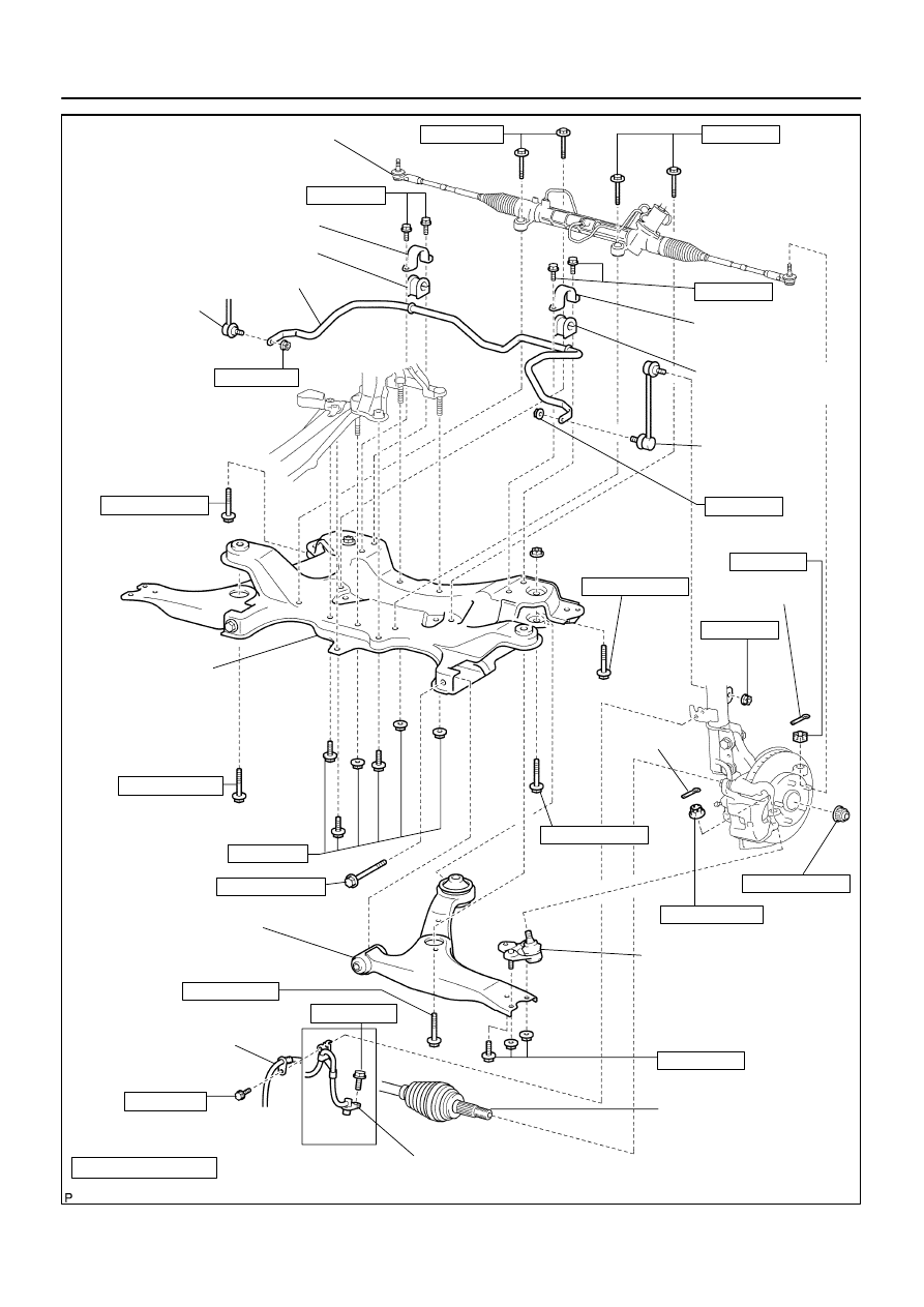
FRONT SUSPENSION
COMPONENTS
C95200
N
⋅
m (kgf
⋅
cm, ft
⋅
lbf) : Specified torque
Non–reusable part
Rack & Pinion Power
Steering Gear Assy
Front Stabilizer Bracket No.1 RH
Front Stabilizer Bar Bush No.1
Stabilizer Bar Front
Front Stabilizer
Link Assy RH
Front Stabilizer
Bracket No.1 LH
Front Stabilizer Bar
Bush No.1
Front Stabilizer
Link Assy LH
Front Suspension
Crossmember
Sub–assy
Front Suspension Arm
Sub–assy Lower No.1 LH
Front Flexible Hose
Speed Sensor Front LH
Lower Ball Joint Assy
Front LH
Cotter Pin
Cotter Pin
w/ ABS:
Front Drive Shaft
Assy LH
29 (296, 21)
29 (296, 21)
113 (1,152, 83)
89 (908, 66)
216 (2,203, 159)
137 (1,397, 101)
49 (500, 36)
74 (755, 55)
157 (1,601, 116)
74 (755, 55)
113 (1,152, 83)
19 (194, 14)
58 (591, 43)
58 (591, 43)
19 (194, 14)
74 (755, 55)
157 (1,601, 116)
52 (530, 38)
103 (1,050, 76)
137 (1,397, 101)
26–4
–
FRONT SUSPENSION
FRONT SUSPENSION
1235
Author:
Date:
2004 COROLLA (RM1037U)
2607T–01
C95205
A
B
C
D
SA3213
A
D
B
Front
C
C90321
–
FRONT SUSPENSION
FRONT WHEEL ALIGNMENT
26–5
1236
Author:
Date:
2004 COROLLA (RM1037U)
FRONT WHEEL ALIGNMENT
ADJUSTMENT
1.
INSPECT TIRE(See page
28–1
)
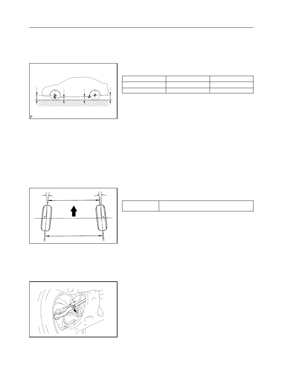
2.
MEASURE VEHICLE HEIGHT
Vehicle height:
USA, Canada
Mexico
Front (A – B)
87 mm (3.43 in.)
72 mm (2.84 in.)
Rear (D – C)
43 mm (1.69 in.)
29 mm (1.14 in.)
Measuring points:
A: Ground clearance of front wheel center
B: Ground clearance of lower suspension arm front
bolt center
C: Ground clearance of axle beam set bolt center
D: Ground clearance of rear wheel center
NOTICE:
Before inspecting the wheel alignment, adjust the vehicle
height to the specified value.
If the vehicle height is not the specified value, try to adjust it by
pushing down on or lifting the body.
3.
INSPECT TOE–IN
Toe–in:
Toe–in
(total)
A + B: 0
° ±
12’ (0
° ±
0.2
°
)
C – D: 0
±
2 mm (0
±
0.08 in.)
If the toe–in is not within the specified value, adjust it at the rack
ends.
4.
ADJUST TOE–IN
(a)
Remove the rack boot set clips.
(b)
Loosen the tie rod end lock nuts.
(c)
Turn the right and left rack ends by an equal amount to
adjust the toe–in.
HINT:
Try to adjust the toe–in to the center of the specified value.
(d)
Make sure that the lengths of the right and left rack ends
are the same.
Rack end length difference: 1.5 mm (0.059 in.) or less
(e)
Torque the tie rod end lock nuts.
Torque: 74 N·m (755 kgf·cm, 55 ft·lbf)
(f)
Place the boots on the seats and install the clips.
HINT:
Make sure that the boots are not twisted.
SA0028
A
B
Front
A
B
A: Inside
B: Outside
Z03382
Alignment
Tester
Gauge
F13683
26–6
–
FRONT SUSPENSION
FRONT WHEEL ALIGNMENT
1237
Author:
Date:
2004 COROLLA (RM1037U)
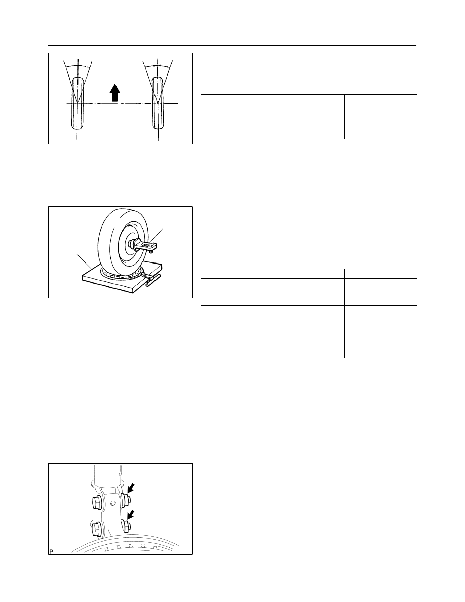
5.
INSPECT WHEEL ANGLE
(a)
Turn the steering wheel fully and measure the turning
angle.
Wheel turning angle:
USA, Canada
Mexico
Inside wheel
37°
06’
±
2
°
(37.10° ± 2°)
37
°
16’
±
2
°
(37.27° ± 2°)
Outside wheel:
Reference
31°
49’
(31.82°)
32°
08’
(32.13°)
If the right and left inside wheel angles differ from the specified
value, check the right and left rack end lengths.
6.
INSPECT CAMBER, CASTER AND STEERING AXIS
INCLINATION
(a)
Install the camber–caster–kingpin gauge or position ve-
hicle on wheel alignment tester.
(b)
Inspect the camber, caster and steering axis inclination.
Camber, caster and steering axis inclination:
USA, Canada
Mexico
Camber
Right–left error
–0
°
32’
±
45’
(–0.53
° ±
0.75
°
)
45’ (0.75
°
) or less
–0
°
22’
±
45’
(–0.37
° ±
0.75
°
)
45’ (0.75
°
) or less
Caster
Right–left error
2°
50’
±
45’
(2.83
° ±
0.75
°
)
45’ (0.75
°
) or less
2°
43’
±
45’
(2.72
° ±
0.75
°
)
45’ (0.75
°
) or less
Steering axis inclination
Right–left error
11°
21’
±
45’
(11.35
° ±
0.75
°
)
45’ (0.75
°
) or less
10°
59’’
±
45’
(10.98° ±
0.75
°)
45’ (0.75
°
) or less
If the caster and steering axis inclination are not within the spe-
cified values, after the camber has been correctly adjusted, re-
check the suspension parts for damaged and/or worn out parts.
7.
ADJUST CAMBER
NOTICE:
After the camber has been adjusted, inspect the toe–in.
(a)
Remove the front wheel.
(b)
Remove the 2 nuts on the lower side of the shock absorb-
er assy front LH.
NOTICE:
When removing nut, stop the bolt from rotating and loosen
the nut.
(c)
Clean the installation surfaces of the shock absorber assy
front LH and the steering knuckle.
(d)
Temporarily install the 2 nuts.
F13684
F13685
2
1
F12938
Bolt
Adjusting
Value
Set Bolt
Adjusting Bolt
90105–15001
90105–15004 90105–15005 90105–15006
1
2
1
2
1
2
1
2
1 Dot
2 Dots
3 Dots
–1
°
30’ – –1
°
15’
–1
°
15’ – –1
°
00’
–1
°
00’ – –45’
–45’ – –30’
–30’ – –15’
0’ – 15’
15’ – 30’
30’ – 45’
45’ – 1
°00’
1
°
00’ – 1
°
15’
–15’ – 0’
1
°
15’ – 1
°
30’
–
FRONT SUSPENSION
FRONT WHEEL ALIGNMENT
26–7
1238
Author:
Date:
2004 COROLLA (RM1037U)
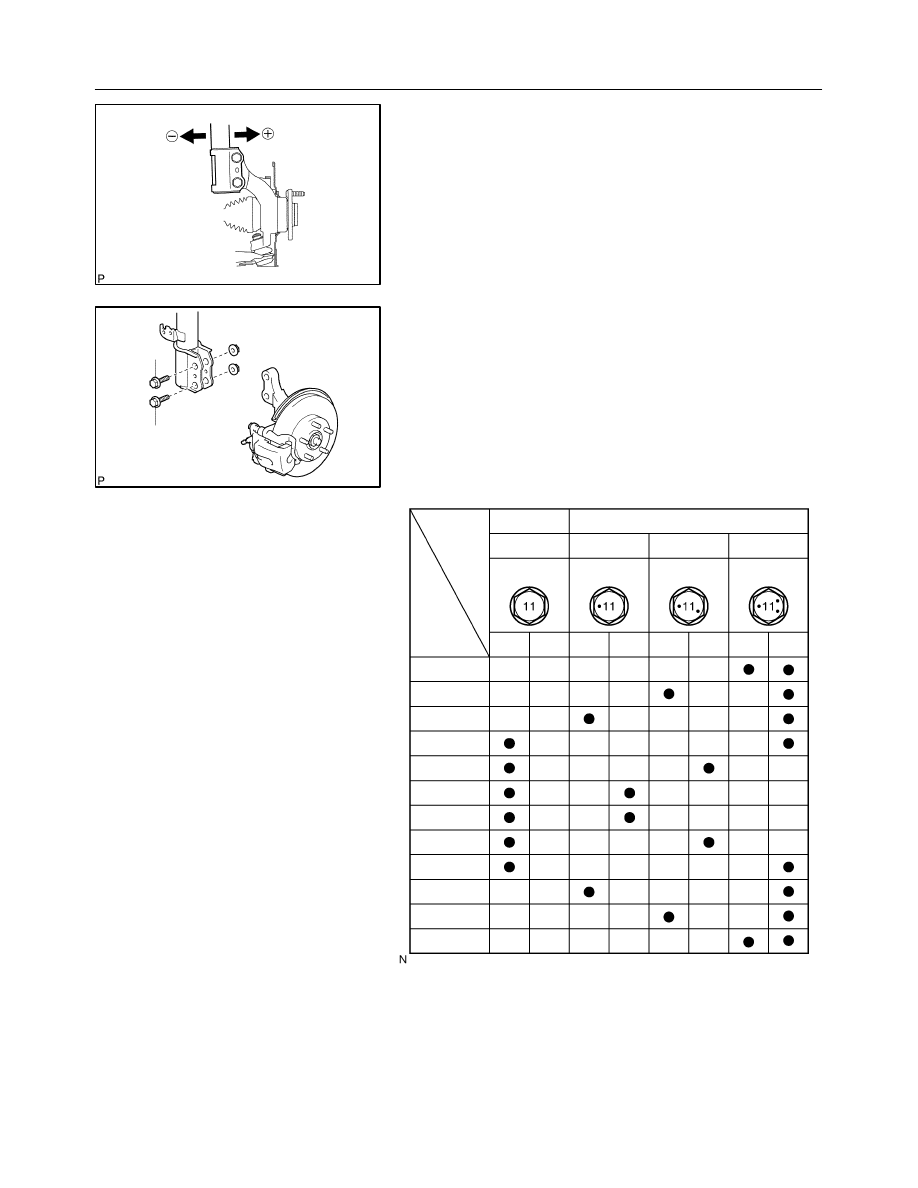
(e)
Adjust the camber by pushing or pulling the lower side of
the shock absorber in the direction in which the camber
adjustment is required.
(f)
Tighten the nuts.
Torque: 153 N
⋅
m (1,560 kgf
⋅
cm, 113 ft
⋅
lbf)
(g)
Install the front wheel.
Torque: 103 N·m (1,050 kgf·cm, 76 ft·lbf)
(h)
Check the camber.
HINT:
S
Try to adjust the camber to the center of the specified val-
ue.
S
Adjusting value for the set bolts is –1
_
30’ – 0
_
30’ (–1.5
_
– 0.5
_
).
If the camber is not within the specified value, using the follow-
ing table, estimate how much additional camber adjustment will
be required, and select the camber adjusting bolt.
(i)
Perform the steps mentioned above again. At step (e), re-
place 1 or 2 selected bolts.
HINT:
When replacing the 2 bolts, replace 1 bolt at a time.
2607V–01
F13686
C80880
F13687
C95202
26–8
–
FRONT SUSPENSION
FRONT SHOCK ABSORBER WITH COIL SPRING
1239
Author:
Date:
2004 COROLLA (RM1037U)
FRONT SHOCK ABSORBER WITH COIL SPRING
OVERHAUL
HINT:
COMPONENTS: See page
26–3
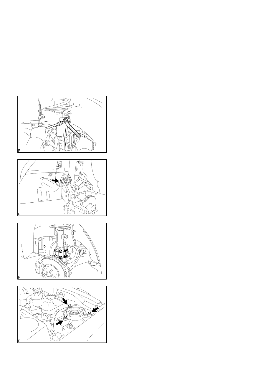
1.
REMOVE FRONT WHEEL
2.
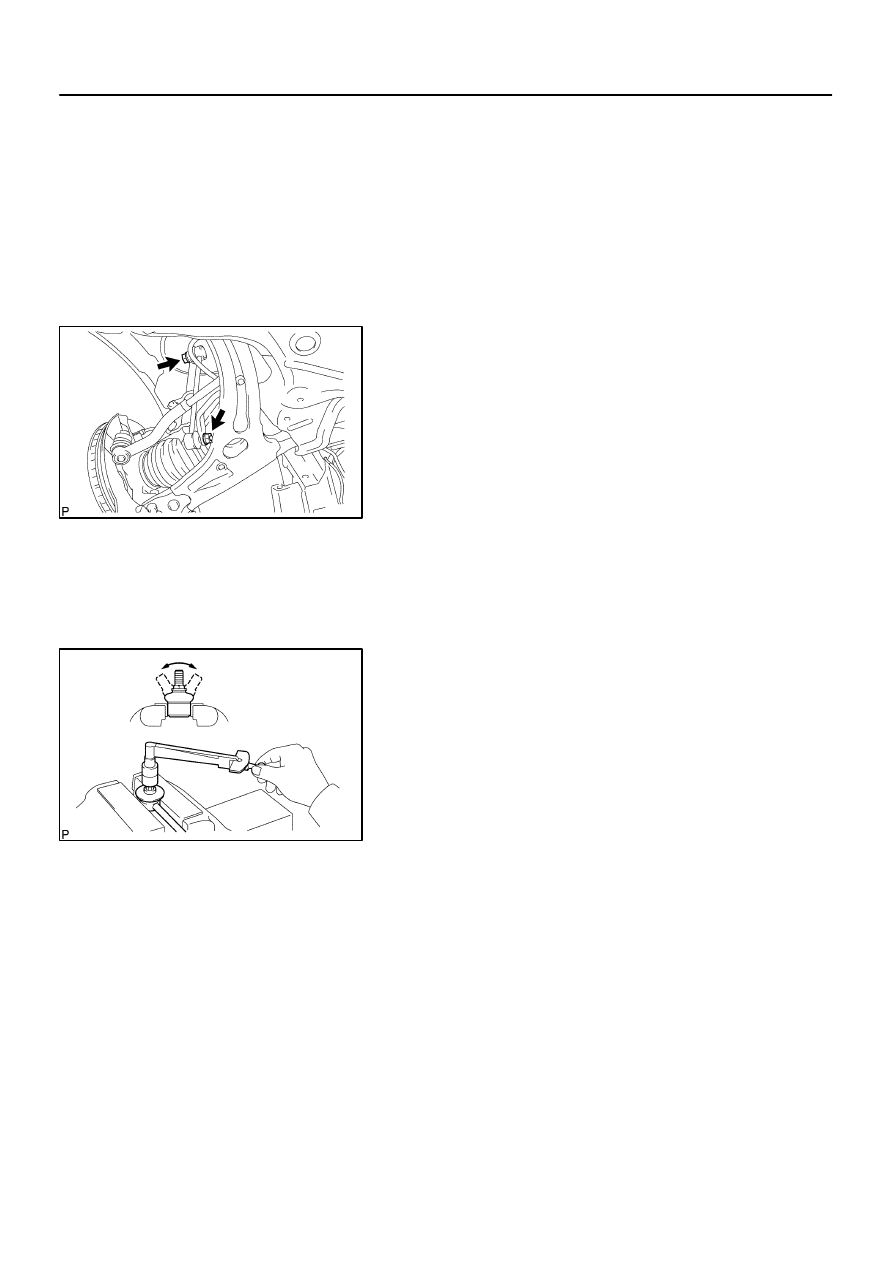
DISCONNECT FRONT STABILIZER LINK ASSY LH
(a)
Remove the nut and disconnect the front stabilizer link
assy LH from the shock absorber assy front LH.
HINT:
If the ball joint turns together with the nut, use a hexagon (6 mm)
wrench to hold the stud.
3.
DISCONNECT FRONT FLEXIBLE HOSE
(a)
w/ ABS:
Remove the bolt, disconnect the front flexible hose No. 1
and speed sensor front LH.
(b)
w/o ABS:
Remove the bolt, disconnect the front flexible hose.
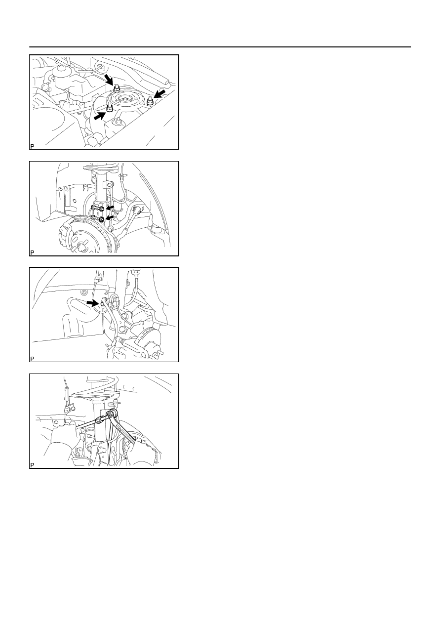
4.
REMOVE FRONT SHOCK ABSORBER WITH COIL
SPRING
(a)
Remove the 2 bolts and nuts on the lower side of the
shock absorber assy front LH.
NOTICE:
When removing the bolt, stop the bolt from rotating and
loosen the nut.
(b)
Remove the 3 nuts on the upper side of the shock absorb-
er assy front LH.
(c)
Remove the front shock absorber with the coil spring.
F13688
28 mm
(1.1 in.)
F13689
SST
F13690
SST
F13691
–
FRONT SUSPENSION
FRONT SHOCK ABSORBER WITH COIL SPRING
26–9
1240
Author:
Date:
2004 COROLLA (RM1037U)
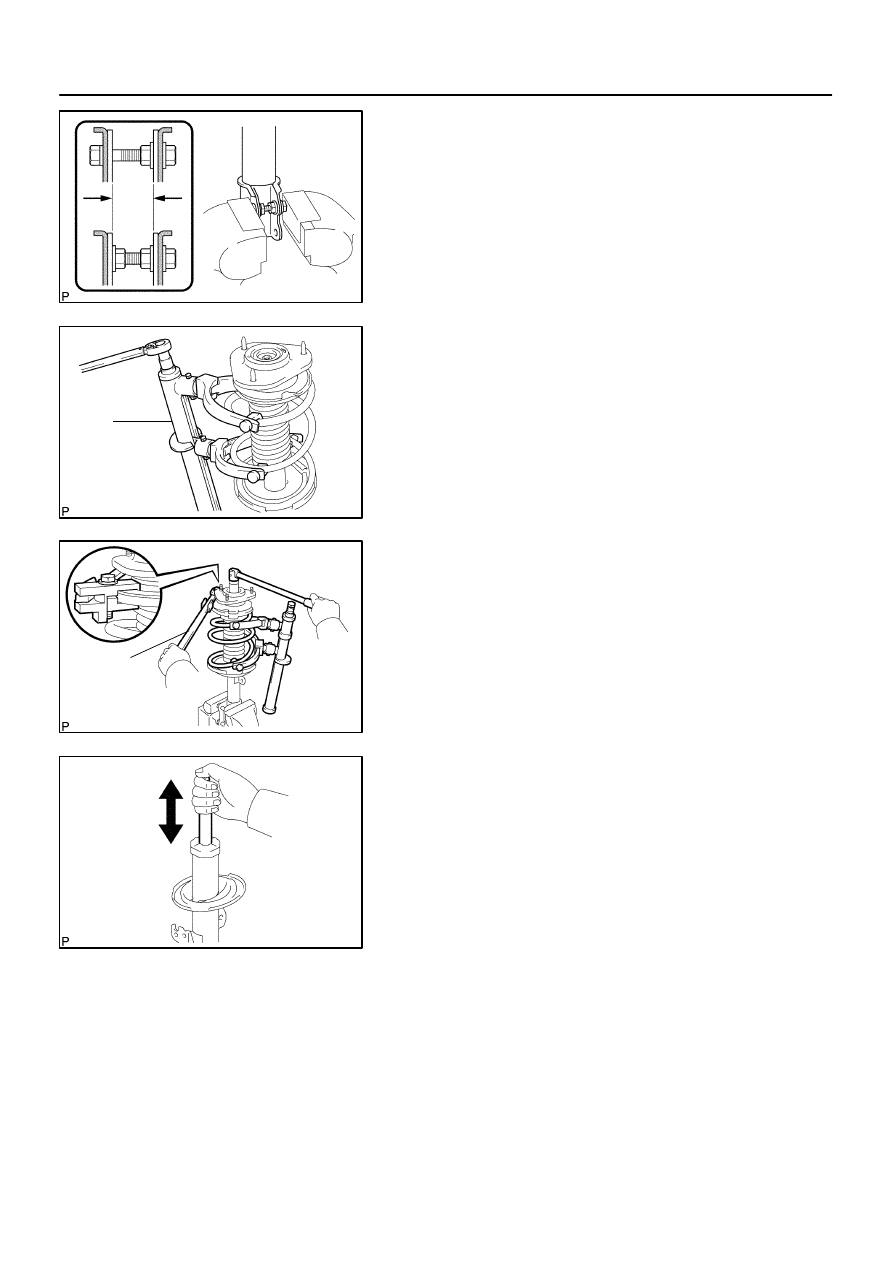
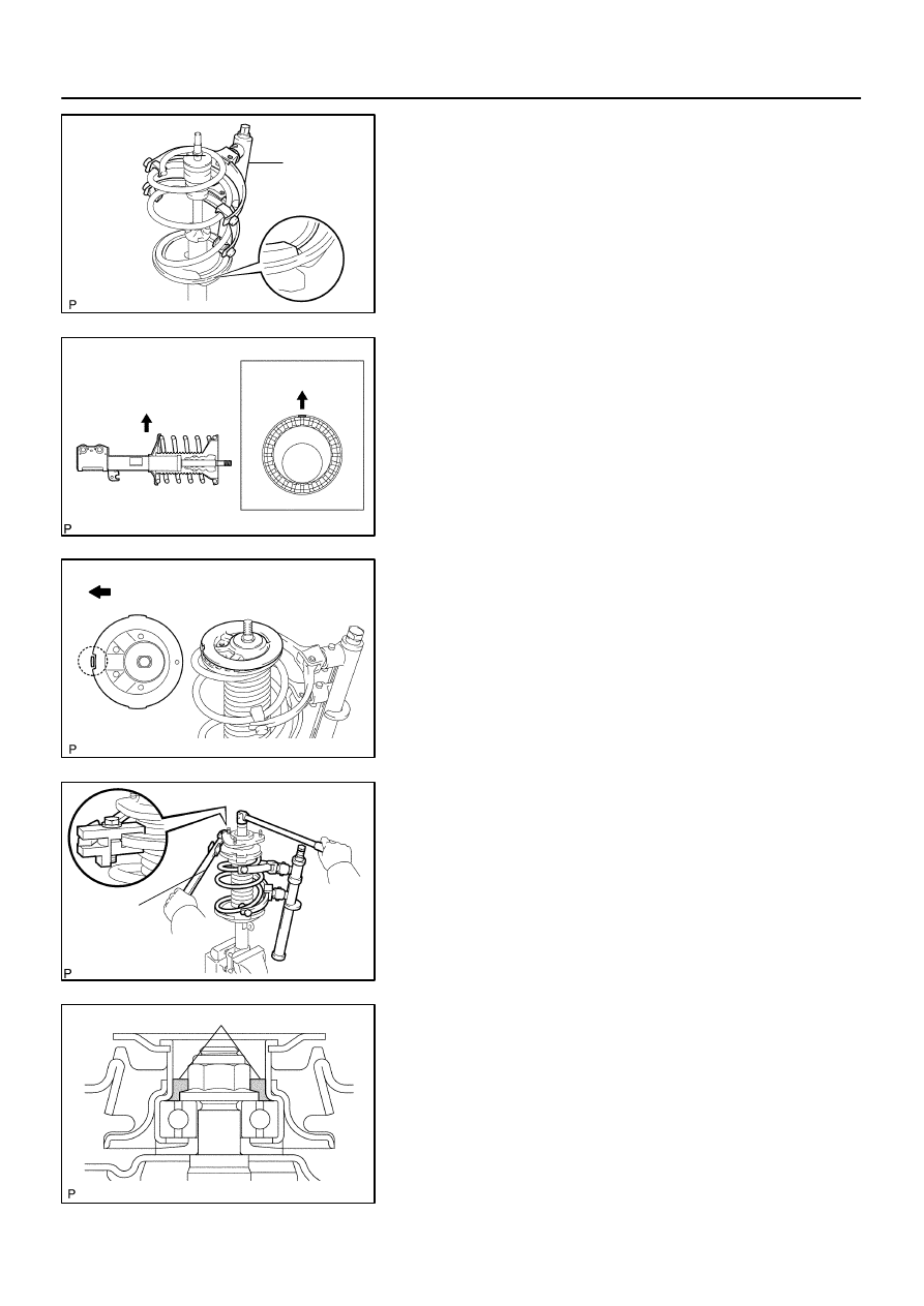
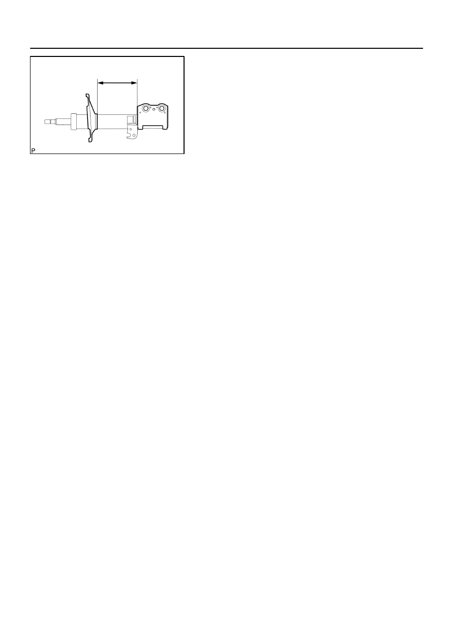
5.
FIX FRONT SHOCK ABSORBER WITH COIL SPRING
(a)
Install 2 nuts and a bolt to the bracket at the lower side of
the shock absorber assy front LH and secure it in a vise.
6.
REMOVE SHOCK ABSORBER ASSY FRONT LH
(a)
Remove the front suspension support dust cover LH from
the front suspension support sub–assy LH.
(b)
Using SST, compress the front coil spring LH.
SST
09727–30021
NOTICE:
Do not use an impact wrench. It will damage the SST.
(c)
Using SST to hold the front coil spring seat upper LH, re-
move the nut.
SST
09729–22031
(d)
Remove the front suspension support sub–assy LH, front
suspension support LH dust seal, front coil spring seat
upper LH, front coil spring insulator upper LH, front coil
spring LH, front spring bumper LH and front coil spring in-
sulator lower LH.
7.
INSPECT SHOCK ABSORBER ASSY FRONT LH
(a)
Compress and extend the shock absorber rod and check
that there is no abnormal resistance or unusual sound
during operation.
If there is any abnormality, replace the shock absorber with a
new one.
NOTICE:
When disposing of the shock absorber, see DISPOSAL on
page
26–12
.
8.
INSTALL SHOCK ABSORBER ASSY FRONT LH
(a)
Install the front coil spring insulator lower LH onto the
shock absorber assy front LH.
(b)
Install the front spring bumper LH to the shock absorber
piston rod.
F40271
SST
F13692
Outside
Outside
F40272
Outside
F13690
SST
F40273
MP Grease No.2
26–10
–
FRONT SUSPENSION
FRONT SHOCK ABSORBER WITH COIL SPRING
1241
Author:
Date:
2004 COROLLA (RM1037U)
(c)
Using SST, compress the front coil spring LH.
SST
09727–30021
NOTICE:
Do not use an impact wrench. It will damage the SST.
(d)
Install the front coil spring LH to the shock absorber assy
front LH.
HINT:
Fit the lower end of the front coil spring LH into the gap of the
spring lower seat.
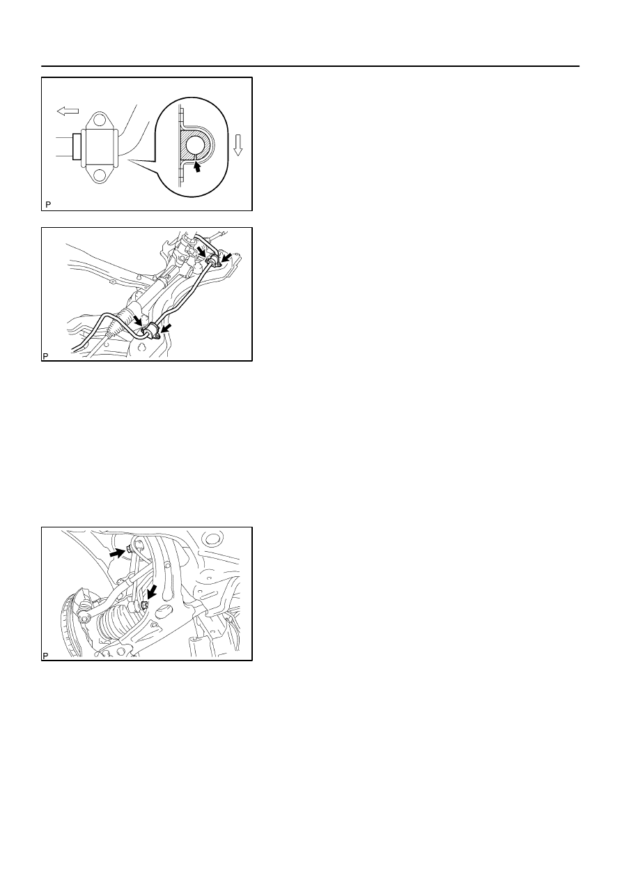
(e)
Install the front coil spring insulator upper LH as shown in
the illustration.
(f)
Install the front coil spring seat upper LH to the shock ab-
sorber assy front LH with the mark facing the outside of
the vehicle.
(g)
Install the front suspension support LH dust seal and front
suspension support sub–assy LH.
(h)
Using SST to hold the front coil spring seat upper LH,
install a new nut.
SST
09729–22031
Torque: 47 N
⋅
m (479 kgf
⋅
cm, 35 ft
⋅
lbf)
(i)
Remove the SST.
(j)
Install the front suspension support dust cover LH.
(k)
Apply MP grease No.2 into the suspension support sub–
assy LH.
CAUTION:
Do not touch grease on rubber surface of upper support.
C95202
F13687
C80880
F13686
–
FRONT SUSPENSION
FRONT SHOCK ABSORBER WITH COIL SPRING
26–11
1242
Author:
Date:
2004 COROLLA (RM1037U)
9.
INSTALL FRONT SHOCK ABSORBER WITH COIL
SPRING
(a)
Install the shock absorber with the 2 bolts.
(b)
Install the 3 nuts to the upper side of front shock absorber
with coil spring.
Torque: 39 N
⋅
m (398 kgf
⋅
cm, 29 ft
⋅
lbf)
(c)
Install the 2 bolts and nuts to the lower side of front shock
absorber with coil spring.
Torque: 153 N
⋅
m (1,560 kgf
⋅
cm, 113 ft
⋅
lbf)
NOTICE:
When installing bolt, stop the bolt from rotating and torque
the nut.
10.
INSTALL FRONT FLEXIBLE HOSE
(a)
w/ ABS:
Install the front flexible hose and speed sensor front LH
with the bolt.
Torque: 29 N
⋅
m (296 kgf
⋅
cm, 21 ft
⋅
lbf)
(b)
w/o ABS:
Install the front flexible hose with the bolt.
Torque: 29 N
⋅
m (296 kgf
⋅
cm, 21 ft
⋅
lbf)
11.
INSTALL FRONT STABILIZER LINK ASSY LH
(a)
Install the front stabilizer link assy LH with the nut.
Torque: 74 N
⋅
m (755 kgf
⋅
cm, 55 ft
⋅
lbf)
HINT:
If the ball joint turns together with the nut, use a hexagon
wrench (6 mm) to hold the stud.
12.
INSTALL FRONT WHEEL
Torque: 103 N
⋅
m (1,050 kgf
⋅
cm, 76 ft
⋅
lbf)
13.
INSPECT AND ADJUST FRONT WHEEL ALIGNMENT(See page
26–5
)
2607W–01
F13693
26–12
–
FRONT SUSPENSION
FRONT SHOCK ABSORBER WITH COIL SPRING
1243
Author:
Date:
2004 COROLLA (RM1037U)
DISPOSAL
1.
DISPOSE SHOCK ABSORBER ASSY FRONT LH
(a)
Fully extend the shock absorber piston rod.
(b)
Using a drill, make a hole in the cylinder as shown in the
illustration to discharge the gas inside.
CAUTION:
When drilling, chips may fly out, work carefully.
The gas is colorless, odorless and non–poisonous.
2607X–01
C80293
C86742
–
FRONT SUSPENSION
FRONT SUSPENSION ARM SUB–ASSY LOWER NO.1
LH
26–13
1244
Author:
Date:
2004 COROLLA (RM1037U)
FRONT SUSPENSION ARM SUB–ASSY LOWER NO.1 LH
REPLACEMENT
HINT:
COMPONENTS: See page
26–3
1.
REMOVE FRONT WHEEL
2.
DISCONNECT FRONT STABILIZER LINK ASSY LH (LH (A/T) POSITION)(See page
26–8
)
3.
DISCONNECT FRONT STABILIZER LINK ASSY RH (LH (A/T) POSITION)
HINT:
Remove the RH side by the same procedures as the LH side.
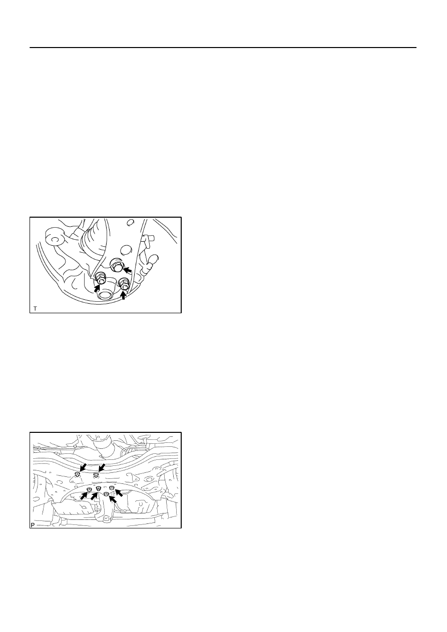
4.
SEPARATE FRONT SUSPENSION ARM SUB–ASSY
LOWER NO.1 LH
(a)
Remove the bolt and 2 nuts, and separate the front sus-
pension arm sub–assy lower No.1 LH from the lower ball
joint assy front LH.
5.
SEPARATE FRONT SUSPENSION ARM SUB–ASSY LOWER NO.1 RH (LH (A/T) POSITION)
HINT:
Remove the RH side by the same procedures as the LH side.
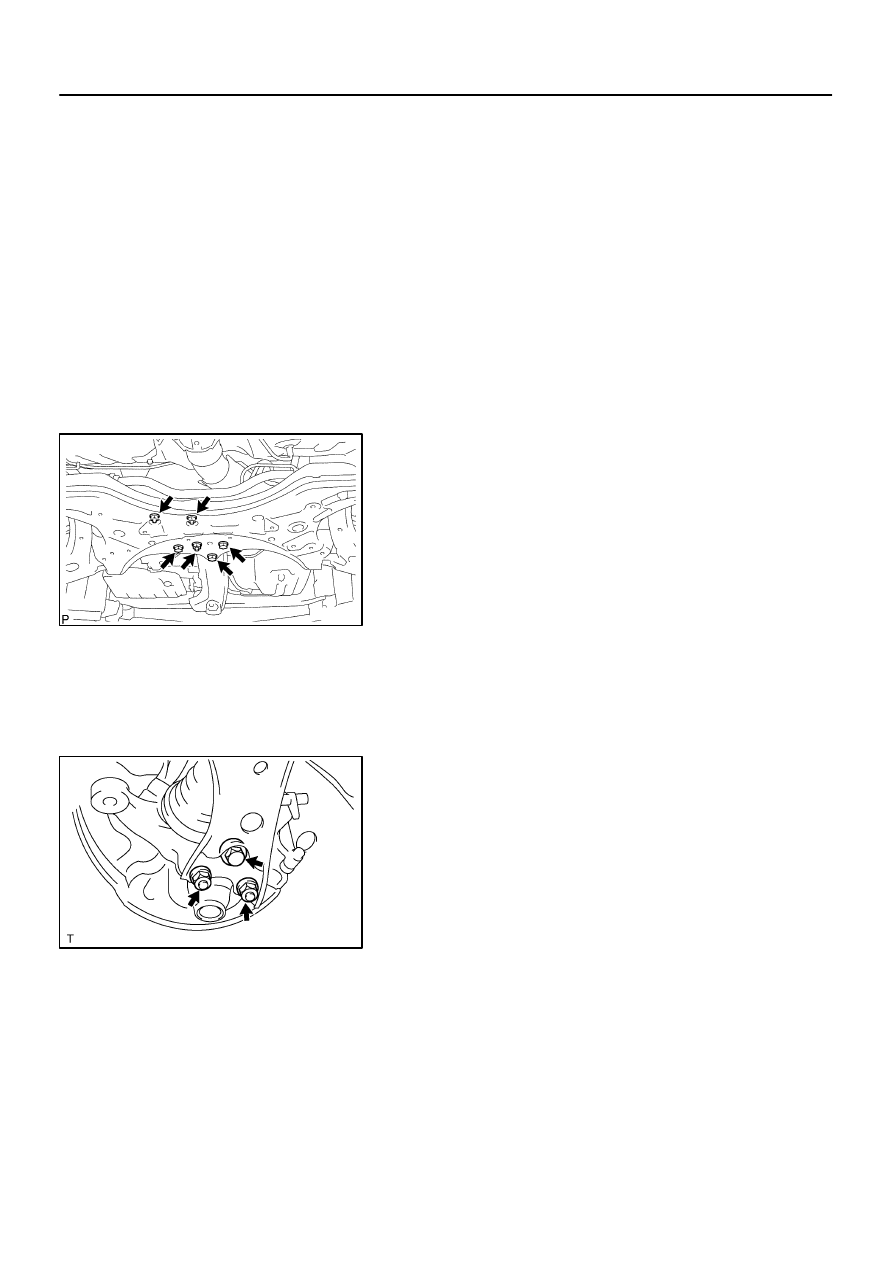
6.
SEPARATE RACK & PINION POWER STEERING GEAR ASSY (LH (A/T) POSITION)
(a)
Remove the 4 bolts, separate the rack & pinion power steering gear assy.
NOTICE:
Loosen the bolt since the nut cannot be rotated.
(b)
Suspend the rack & pinion power steering gear assy.
7.
SUSPEND ENGINE ASSY (LH (A/T) POSITION)(See page
40–9
)
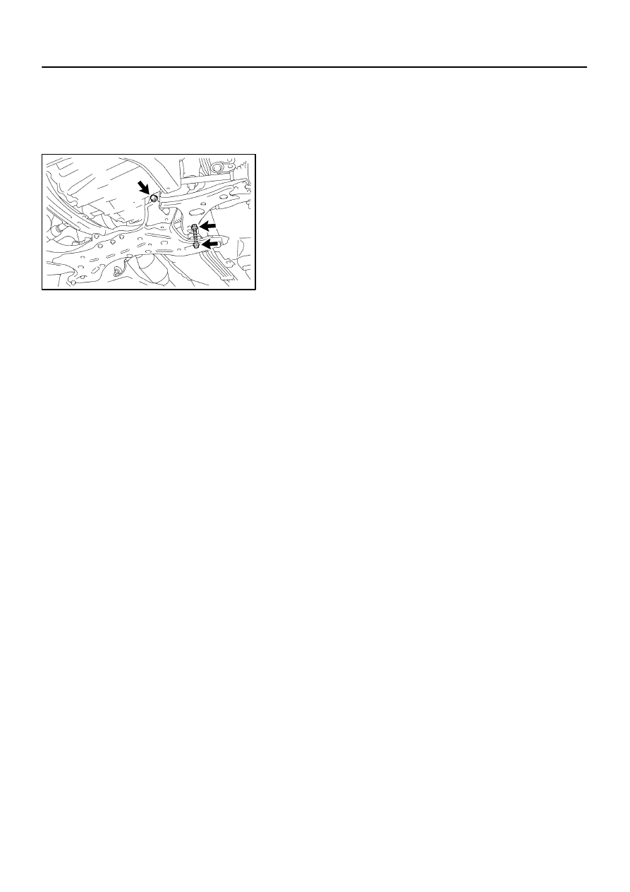
8.
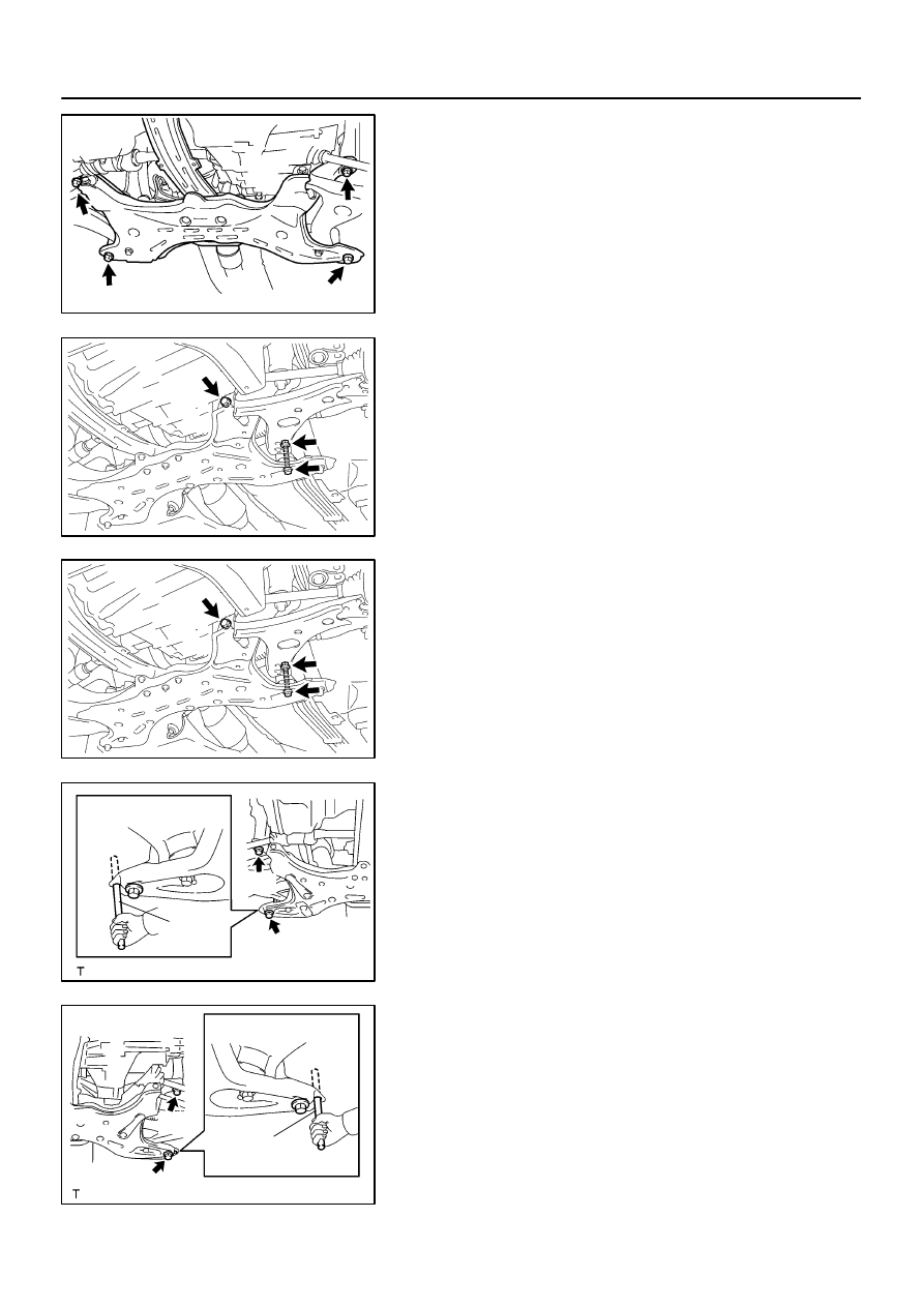
SEPARATE FRONT SUSPENSION CROSSMEMBER
SUB–ASSY (LH (A/T) POSITION)
(a)
Remove the 3 bolts and 3 nuts, disconnect the transverse
engine engine mounting insulator and engine mounting
member sub–assy center from the front suspension
crossmember sub–assy.
C87404
C87403
C87403
C64941
SST
A
B
C65019
C64940
SST
A
B
C65020
26–14
–
FRONT SUSPENSION
FRONT SUSPENSION ARM SUB–ASSY LOWER NO.1
LH
1245
Author:
Date:
2004 COROLLA (RM1037U)
(b)
Remove the 4 bolts.
(c)
Lower the transmission jack, remove the front suspension
crossmember sub–assy.
9.
REMOVE FRONT SUSPENSION ARM SUB–ASSY
LOWER NO.1 LH
(a)
Remove the 2 bolts, nut and front suspension arm sub–
assy lower No.1 LH from the front suspension crossmem-
ber sub–assy.
10.
TEMPORARY TIGHTEN FRONT SUSPENSION ARM
SUB–ASSY LOWER NO.1 LH
(a)
Install the front suspension arm sub–assy lower No. 1 LH,
temporarily tighten the 2 bolts and nut.
11.
INSTALL FRONT SUSPENSION CROSSMEMBER
SUB–ASSY (LH (A/T) POSITION)
(a)
Lift the front suspension crossmember sub–assy up with
a transmission jack.
(b)
Insert SST to the base hole of the RH side crossmember
and RH side of the vehicle.
SST
09670–00010
(c)
Tighten the bolt temporarily in the order A and B.
(d)
Insert SST to the base hole of the LH side of crossmem-
ber and LH side of the vehicle.
SST
09670–00010
(e)
Tighten the bolt temporarily in the order A and B.
(f)
Insert SST to the base hole of the RH side of crossmem-
ber and RH side of the vehicle.
SST
09670–00010
C86742
C80293
–
FRONT SUSPENSION
FRONT SUSPENSION ARM SUB–ASSY LOWER NO.1
LH
26–15
1246
Author:
Date:
2004 COROLLA (RM1037U)
(g)
Then tighten the bolt A and B by the specified torque.
Torque:
Bolt A: 157 N
⋅
m (1,601 kgf
⋅
cm, 116 ft
⋅
lbf)
Bolt B: 113 N
⋅
m (1,152 kgf
⋅
cm, 83 ft
⋅
lbf)
(h)
Insert SST to the base hole of the LH side of crossmem-
ber and LH side of the vehicle.
SST
09670–00010
(i)
Tighten the bolt A and B by the specified torque.
Torque:
Bolt A: 157 N
⋅
m (1,601 kgf
⋅
cm, 116 ft
⋅
lbf)
Bolt B: 113 N
⋅
m (1,152 kgf
⋅
cm, 83 ft
⋅
lbf)
(j)
Connect the transverse engine engine mounting insula-
tor and engine mounting member sub–assy center to the
front suspension crossmember sub–assy.
(k)
Install the 3 bolts and 3 nuts.
Torque: 52 N
⋅
m (530 kgf
⋅
cm, 38 ft
⋅
lbf)
12.
INSTALL RACK & PINION POWER STEERING GEAR ASSY (LH (A/T) POSITION)
(a)
Install the rack & pinion power steering gear assy with the 4 bolts.
Torque: 58 N
⋅
m (591 kgf
⋅
cm, 43 ft
⋅
lbf)
13.
INSTALL FRONT SUSPENSION ARM SUB–ASSY
LOWER NO.1 LH
(a)
Install the front suspension arm sub–assy lower No.1 LH
with the 2 nuts and bolt to the lower ball joint assy front LH.
Torque: 89 N
⋅
m (908 kgf
⋅
cm, 66 ft
⋅
lbf)
14.
INSTALL FRONT SUSPENSION ARM SUB–ASSY LOWER NO.1 RH (LH (A/T) POSITION)
HINT:
Install the RH side by the same procedures as the LH side.
15.
INSTALL FRONT STABILIZER LINK ASSY LH (LH (A/T) POSITION)(See page
26–8
)
16.
INSTALL FRONT STABILIZER LINK ASSY RH (LH (A/T) POSITION)
HINT:
Install the RH side by the same procedure as the LH side.
C87403
26–16
–
FRONT SUSPENSION
FRONT SUSPENSION ARM SUB–ASSY LOWER NO.1
LH
1247
Author:
Date:
2004 COROLLA (RM1037U)
17.
STABILIZE SUSPENSION
(a)
Install the front wheel and jack down the vehicle.
Torque: 103 N
⋅
m (1,050 kgf
⋅
cm, 76 ft
⋅
lbf)
(b)
Bounce the vehicle up and down several times to stabilize the suspension.
18.
FULLY TIGHTEN FRONT SUSPENSION ARM
SUB–ASSY LOWER NO.1 LH
(a)
Fully tighten the 2 bolts and nut.
Torque: 137 N
⋅
m (1,397 kgf
⋅
cm, 101 ft
⋅
lbf)
NOTICE:
Tighten the bolt since the nut cannot be rotated.
19.
INSPECT AND ADJUST FRONT WHEEL ALIGNMENT(See page
26–5
)
2607Y–04
C54719
C95204
SST
ZX1712
–
FRONT SUSPENSION
LOWER BALL JOINT ASSY FRONT LH
26–17
1248
Author:
Date:
2004 COROLLA (RM1037U)
LOWER BALL JOINT ASSY FRONT LH
REPLACEMENT
HINT:
COMPONENTS: See page
26–3
1.
INSPECT LOWER BALL JOINT ASSY FRONT LH
(a)
Jack up front side of the vehicle.
(b)
Check the rattle of the lower ball joint assy front LH.
2.
REMOVE FRONT WHEEL
3.
REMOVE FRONT AXLE HUB LH NUT(See page
30–6
)
SST
09930–00010
4.
DISCONNECT SPEED SENSOR FRONT LH (W/ ABS)(See page
30–6
)
5.
SEPARATE TIE ROD END SUB–ASSY LH(See page
30–6
)
SST
09628–62011
6.
SEPARATE FRONT SUSPENSION ARM SUB–ASSY LOWER NO.1 LH(See page
30–6
)
7.
SEPARATE FRONT AXLE ASSY LH(See page
30–6
)
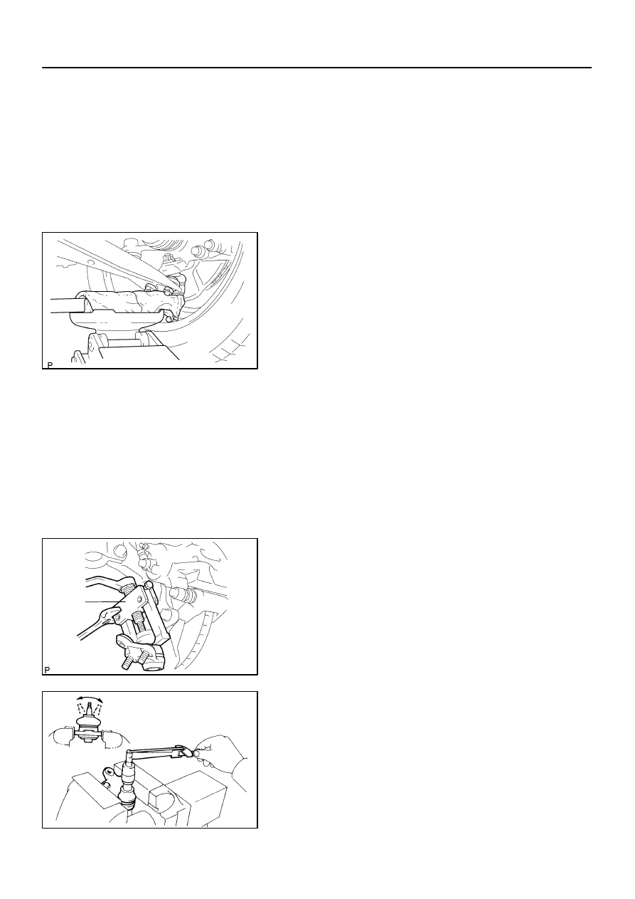
8.
REMOVE LOWER BALL JOINT ASSY FRONT LH
(a)
Remove the cotter pin and castle nut.
(b)
Using SST, remove the lower ball joint assy from the
steering knuckle LH.
SST
09628–62011
9.
INSPECT LOWER BALL JOINT ASSY FRONT LH
(a)
As shown in the illustration, flip the ball joint stud back and
forth 5 times, before installing the nut.
(b)
Using a torque wrench, turn the nut continuously at a rate
of 3 – 5 seconds per 1 turn and take the torque reading
on the 5th turn.
Turning torque:
0.98 – 4.9 N
⋅
m (10 – 50 kgf
⋅
cm, 8.7 – 43 in.
⋅
lbf)

26–18
–
FRONT SUSPENSION
LOWER BALL JOINT ASSY FRONT LH
1249
Author:
Date:
2004 COROLLA (RM1037U)
10.
INSTALL LOWER BALL JOINT ASSY FRONT LH
(a)
Install the lower ball joint assy front LH to the steering knuckle LH, tighten the castle nut.
Torque: 103 N
⋅
m (1050 kgf
⋅
cm, 76 ft
⋅
lbf)
(b)
Install a new cotter pin.
11.
INSTALL FRONT AXLE ASSY LH(See page
30–6
)
12.
INSTALL FRONT SUSPENSION ARM SUB–ASSY LOWER NO.1 LH(See page
30–6
)
13.
INSTALL TIE ROD END SUB–ASSY LH(See page
30–6
)
14.
INSTALL SPEED SENSOR FRONT LH (W/ ABS)(See page
30–6
)
15.
INSTALL FRONT AXLE HUB LH NUT(See page
30–6
)
SST
09931–00020
16.
INSTALL FRONT WHEEL
Torque: 103 N
⋅
m (1,050 kgf
⋅
cm, 76 ft
⋅
lbf)
17.
INSPECT AND ADJUST FRONT WHEEL ALIGNMENT(See page
26–5
)
18.
CHECK ABS SPEED SENSOR SIGNAL (W/ ABS)(See page
05–297
)
2607Z–01
C80890
C66721
–
FRONT SUSPENSION
STABILIZER BAR FRONT
26–19
1250
Author:
Date:
2004 COROLLA (RM1037U)
STABILIZER BAR FRONT
REPLACEMENT
HINT:
COMPONENTS: See page
26–3
1.
REMOVE FRONT WHEEL
2.
REMOVE FRONT STABILIZER LINK ASSY LH
(a)
Remove the 2 nuts and stabilizer bar link.
HINT:
If the ball joint turns together with the nut, use a hexagon
wrench (6 mm) to hold the stud.
3.
REMOVE FRONT STABILIZER LINK ASSY RH
HINT:
Remove the RH side by the same procedure as the LH side.
4.
INSPECT FRONT STABILIZER LINK ASSY
(a)
As shown in the illustration, flip the ball joint stud back and
forth 5 times, before installing the nut.
(b)
Using a torque wrench, turn the nut continuously at a rate
of 2 – 4 seconds per 1 turn and take the torque reading
on the 5th turn.
Turning torque:
0.05 – 1.96 N
⋅
m (0.5 – 20 kgf
⋅
cm, 0.4 – 17 in.
⋅
lbf)
5.
SEPARATE FRONT SUSPENSION ARM SUB–ASSY LOWER NO.1 LH(See page
26–13
)
6.
SEPARATE FRONT SUSPENSION ARM SUB–ASSY LOWER NO.1 RH
HINT:
Remove the RH side by the same procedure as the LH side.
7.
SEPARATE RACK & PINION POWER STEERING GEAR ASSY(See page
26–13
)
8.
SUSPEND ENGINE ASSY
AT: (See page
40–9
)
MT: (See page
41–17
)
9.
SEPARATE FRONT SUSPENSION CROSSMEMBER SUB–ASSY(See page
26–13
)
10.
REMOVE STABILIZER BAR FRONT
(a)
Remove the 4 bolts,front stabilizer bracket No.1 LH, front stabilizer bracket No.1 RH, 2 front stabilizer
bar bushes No.1 and stabilizer bar front from the front suspension crossmember sub–assy.
(b)
Remove the 2 front stabilizer bar bushes No.1 from the stabilizer bar front.
C81547
F40197
Inner side
Rear
side
C91627
C80890
26–20
–
FRONT SUSPENSION
STABILIZER BAR FRONT
1251
Author:
Date:
2004 COROLLA (RM1037U)
11.
INSTALL STABILIZER BAR FRONT
(a)
Install 2 front stabilizer bar bushes No.1, front stabilizer
bracket No.1 LH and front stabilizer bracket No.1 RH to
the stabilizer bar front.
HINT:
Install the bushing to the inner side of the bushing stopper on
the stabilizer bar.
(b)
Install the stabilizer bar front and 4 bolts to the front sus-
pension crossmember sub–assy.
Torque: 19 N
⋅
m (194 kgf
⋅
cm, 14 ft
⋅
lbf)
12.
INSTALL FRONT SUSPENSION CROSSMEMBER SUB–ASSY(See page
26–13
)
SST
09670–00010
13.
INSTALL RACK & PINION POWER STEERING GEAR ASSY(See page
26–13
)
14.
INSTALL FRONT SUSPENSION ARM SUB–ASSY LOWER NO.1 LH(See page
26–13
)
15.
INSTALL FRONT SUSPENSION ARM SUB–ASSY LOWER NO.1 RH
HINT:
Install the RH side by the same procedures as the LH side.
16.
INSTALL FRONT STABILIZER LINK ASSY LH
(a)
Install the stabilizer bar link with the 2 nuts.
Torque: 74 N
⋅
m (755 kgf
⋅
cm, 55 ft
⋅
lbf)
HINT:
If the ball joint turns together with the nut, use a hexagon
wrench (6 mm) to hold the stud.
17.
INSTALL FRONT STABILIZER LINK ASSY LH
HINT:
Install the RH side by the same procedure as the LH side.
18.
INSTALL FRONT WHEEL
Torque: 103 N
⋅
m (1,050 kgf
⋅
cm, 76 ft
⋅
lbf)
19.
INSPECT AND ADJUST FRONT WHEEL ALIGNMENT(See page
26–5
)
Wyszukiwarka
Podobne podstrony:
26 Front Suspension
26 Front Suspension
26 Front Suspension
26 Front Suspension
FRONT SUSPENSION
09 front suspension
Jag front suspension xk 120,xk 140,xk 150;mk VII,mk VIII,mk IX
M32c Front Suspension
Front suspension strut
g3 front suspension
13 Front Suspension
ARTICLE SUSPENSION STRUT FRONT REPLACE INSTALL
ARTICLE SUSPENSION STRUT FRONT DISASSEMBLE REASSEMBLE
11 Front Wheel Suspension Steering
ARTICLE SUSPENSION LOWER CONTROL ARM FRONT SERVICE
więcej podobnych podstron