
2601D–02
–
FRONT SUSPENSION
FRONT SUSPENSION SYSTEM
26–1
1913
Author:
Date:
2002 CAMRY REPAIR MANUAL (RM881U)
FRONT SUSPENSION SYSTEM
PROBLEM SYMPTOMS TABLE
Use the table below to help you find the cause of the problem. The numbers indicate the priority of
the likely cause of the problem. Check each part in order. If necessary, replace these parts.
Symptom
Suspect Area
See page
Bottoming
1. Vehicle (Overloaded)
2. Spring (Weak)
3. Shock absorber (Worn)
–
26–9
26–9
Sways/pitches
1. Tire (Worn or improperly inflated)
2. Stabilizer bar (Bent or broken)
3. Shock absorber (Worn)
28–1
26–9
26–9
Front wheel shimmy
1. Tire (Worn or improperly inflated)
2. Wheel (Out of balance)
3. Shock absorber (Worn)
4. Wheel alignment (Incorrect)
5. Ball joint (Worn)
6. Hub bearing (Worn)
7. Steering linkage (Loose or worn)
28–1
28–1
26–9
26–5
27–3
26–17
30–2
–
Abnormal tire wear
1. Tire (Worn or improperly inflated)
2. Wheel alignment (Incorrect)
3. Shock absorber (Worn)
4. Suspension parts (Worn)
28–1
26–5
27–3
26–9
–
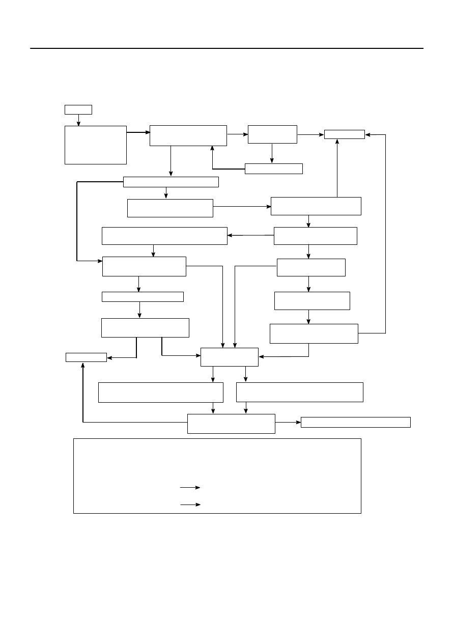
2606O–01
START
Preliminary Check
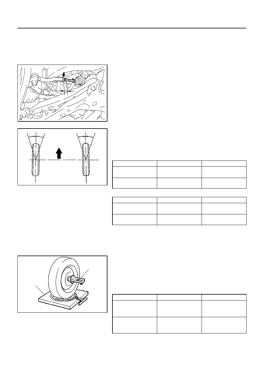
Tire pressure
Vehicle height
Brake dragging
ROAD TEST
Does the vehicle lead/pull?
Cross switch front tire & wheel
assemblies (left & right).
Does the vehicle lead/pull in
same direction as before?
Check front wheel alignment.
Is it within specification?
Adjust front wheel alignment.
Reverse the front left side
tire and rebalance it.
Does the vehicle
lead/pull to the left?
COMPLETE
Are the tires uni–directional type?
Choose the position of front tire & wheel
assemblies where there is least amount of pull.
Increase left front camber and decrease
right front camber until lead/pull is eliminated.
Increase right front camber and decrease
left front camber until lead/pull is eliminated.
NO
YES
YES
NO
YES
YES
NO
YES
NO
COMPLETE
NO
NO
YES
NO
Is there steering
off center?
Adjust front tie rods.
NO
YES
Is the lead/pull stronger
than before?
YES
NOTICE : Do not exceed 1
°
of cross camber.
Do not exceed adjustment range.
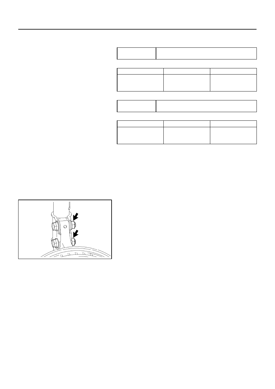
Select a flat road where the vehicle can be driven in a straight line for 100 meters at a constant speed
of 35mph. Please confirm safety and set the steering wheel to its straight position. Drive the vehicle in
a straight line for 100 meters at a constant speed of 35mph without holding the steering wheel.
(1) The vehicle can keep straight but the steering wheel has some angle.
STEERING OFF CENTER (See page
50–4
)
(2) The vehicle cannot keep straight.
STEERING PULL
YES
NO
YES
ROAD TEST
Does the vehicle still lead/pull?
NO
ROAD TEST
Does the vehicle still lead/pull?
ROAD TEST
Does the vehicle still lead/pull?
ROAD TEST
Does the vehicle still lead/pull?
NO
Contact your local retail tire distributor.
YES
*
*
26–2
–
FRONT SUSPENSION
FRONT SUSPENSION SYSTEM
1914
Author:
Date:
2002 CAMRY REPAIR MANUAL (RM881U)
REPAIR
HINT:
This is the repair procedure for vehicle pull.
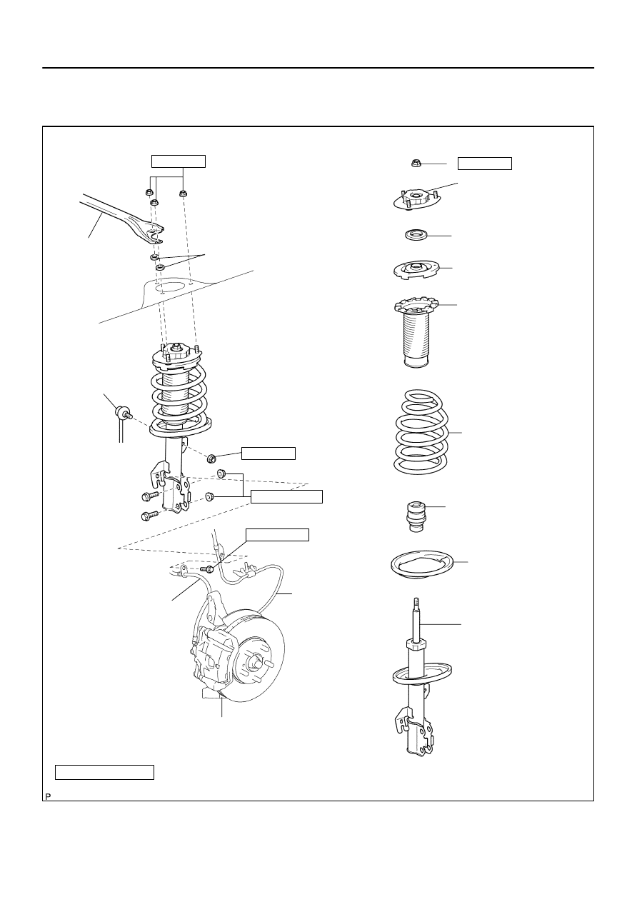
2601C–03
C90258
N·m (kgf·cm, ft·lbf)
: Specified torque
Non–reusable part
Front Suspension
Support Sub–assy LH
Front Suspension
Support Bearing LH
Front Coil Spring
Seat Upper LH
Front Coil Spring
Insulator Upper
LH
Front Coil Spring LH
Front Spring Bumper LH
Front Coil Spring
Insulator Lower LH
Shock Absorber Assy
Front LH
Front Stabilizer
Link Assy LH
w/ABS:
Front Flexible Hose
No. 1
74 (755, 55)
Speed Sensor
Front LH
Front Axle Assy LH
80 (816, 59)
49 (500, 36)
18.8 (192, 14)
SPORT:
Front Suspension
Upper Brace Center
210 (2,141, 155)
Washer
–
FRONT SUSPENSION
FRONT SUSPENSION
26–3
1915
Author:
Date:
2002 CAMRY REPAIR MANUAL (RM881U)
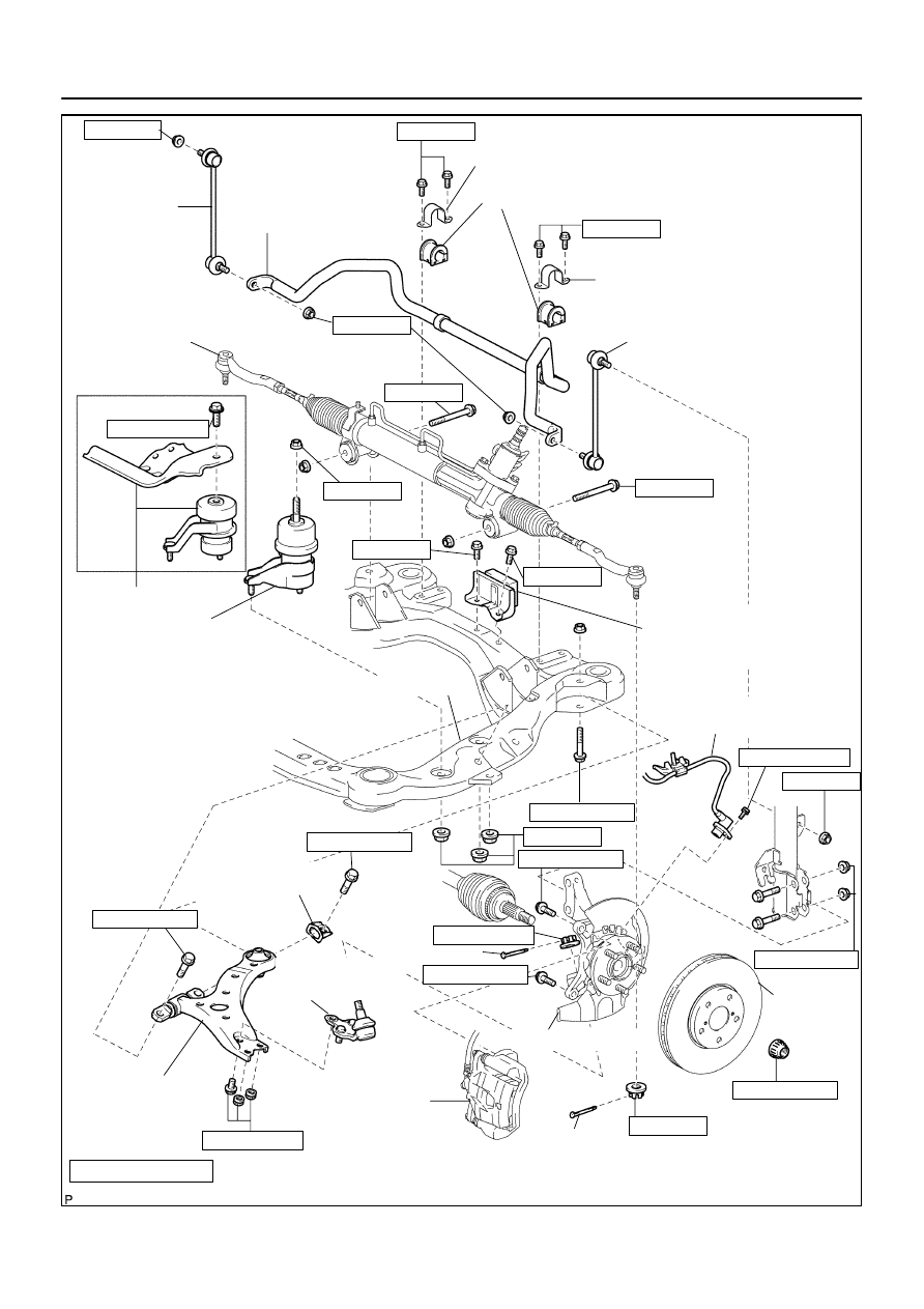
FRONT SUSPENSION
COMPONENTS
C91581
74 (755, 55)
Front Stabilizer
Link Assy RH
Stabilizer Bar Front
Front Stabilizer Bracket No. 1 RH
Front Stabilizer Bar Bush No. 1
Front Stabilizer Bracket No. 1 LH
Front Stabilizer Link Assy LH
Rack & Pinion Power
Steering Gear Assy
MT:
Except 1MZ–FE:
Front Suspension Member
Dynamic Damper
w/ABS:
Speed Sensor
Front LH
Front Frame Assy
Front Lower Arm
Bush Stopper
Lower Ball Joint
Assy Front LH
Front Suspension
Arm Sub–assy
Lower No. 1 LH
Front Brake
Caliper Assy
Front Axle Assy LH
Cotter Pin
19 (194, 14)
Transverse Engine
Engine Mounting
Insulator
Cotter Pin
N·m (kgf·cm, ft·lbf)
: Specified torque
Non–reusable part
Front Disc
74 (755, 55)
143 (1,458, 105)
74 (755, 55)
206 (2,101, 152)
294 (2,998, 217)
49 (500, 36)
87 (887, 64)
123 (1,254 91)
200 (2,039, 148)
200 (2,039, 148)
127 (1,295, 94)
70 (714, 52)
70 (714, 52)
8.0 (82, 71 in.
⋅
lbf)
106.9 (1,090, 79)
106.9 (1,090, 79)
19 (194, 14)
95 (969, 70)
29 (296, 21)
29 (296, 21)
210 (2,141, 155)
26–4
–
FRONT SUSPENSION
FRONT SUSPENSION
1916
Author:
Date:
2002 CAMRY REPAIR MANUAL (RM881U)
2605T–01
C91608
B
Front:
A
C91609
C
Rear:
D
SA3213
A
D
B
Front
C
–
FRONT SUSPENSION
FRONT WHEEL ALIGNMENT
26–5
1917
Author:
Date:
2002 CAMRY REPAIR MANUAL (RM881U)
FRONT WHEEL ALIGNMENT
ADJUSTMENT
1.
INSPECT TIRE(See page
28–1
)
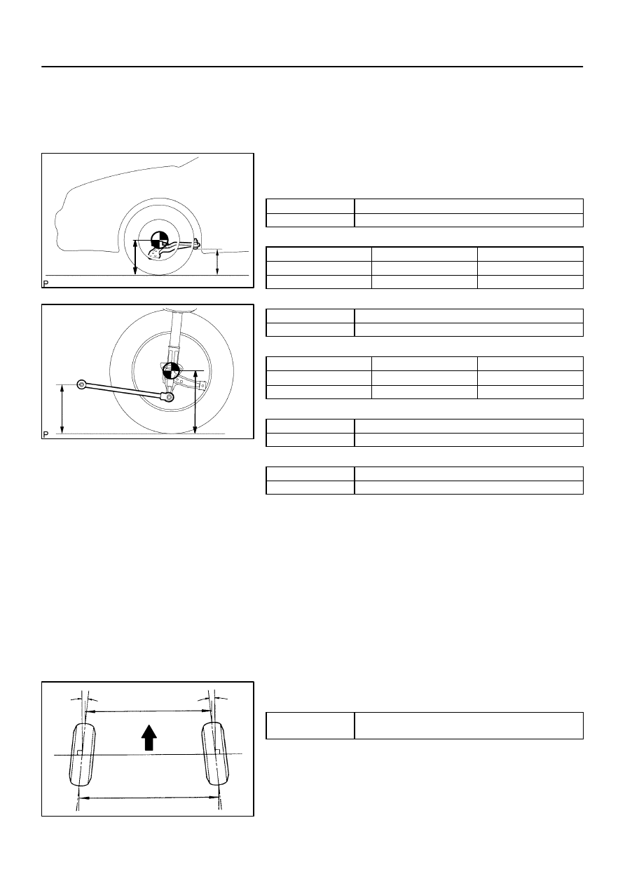
2.
MEASURE VEHICLE HEIGHT
Vehicle height:
1MZ–FE COMFORT:
Front (A – B)
120 mm (4.72 in.)
Rear (D – C)
46 mm (1.81 in.)
1MZ–FE PREMIUM:
USA, Canada
Mexico
Front (A – B)
119 mm (4.69 in.)
106 mm (4.17 in.)
Rear (D – C)
47 mm (1.85 in.)
33 mm (1.30 in.)
1MZ–FE SPORT:
Front (A – B)
120 mm (4.72 in.)
Rear (D – C)
48 mm (1.89 in.)
2AZ–FE COMFORT:
USA, Canada
Mexico
Front (A – B)
119 mm (4.69 in.)
106 mm (4.17 in.)
Rear (D – C)
45 mm (1.77 in.)
33 mm (1.30 in.)
2AZ–FE PREMIUM:
Front (A – B)
120 mm (4.72 in.)
Rear (D – C)
45 mm (1.77 in.)
2AZ–FE SPORT:
Front (A – B)
120 mm (4.72 in.)
Rear (D – C)
48 mm (1.89 in.)
Measuring points:
A: Ground clearance of front wheel center
B: Ground clearance of lower suspension arm No. 2 set bolt
center
C: Ground clearance of strut rod set bolt center
D: Ground clearance of rear wheel center
NOTICE:
Before inspecting the wheel alignment, adjust the vehicle
height to the specified value.
If the vehicle height is not the specified value, try to adjust it by
pushing down on or lifting the body.
3.
INSPECT TOE–IN
Toe–in:
Toe–in
(total)
A + B: 0
°
±
12’ (0
°
±
0.2
°
)
C – D: 0
±
2 mm (0
±
0.08 in.)
If the toe–in is not within the specified value, adjust it at the rack
ends.
4.
ADJUST TOE–IN
(a)
Remove the rack boot set clips.
(b)
Loosen the tie rod end lock nuts.
F40165
SA0028
A
B
Front
A
B
A: Inside
B: Outside
Z03382
Alignment
Tester
Gauge
26–6
–
FRONT SUSPENSION
FRONT WHEEL ALIGNMENT
1918
Author:
Date:
2002 CAMRY REPAIR MANUAL (RM881U)
(c)
Turn the right and left rack ends by an equal amount to
adjust the toe–in.
HINT:
Try to adjust the toe–in to the center of the specified value.
(d)
Make sure that the lengths of the right and left rack ends
are the same.
(e)
Torque the tie rod end lock nuts.
Torque: 74 N·m (755 kgf·cm, 55 ft·lbf)
(f)
Place the boots on the seats and install the clips.
HINT:
Make sure that the boots are not twisted.
5.
INSPECT WHEEL ANGLE
(a)
Turn the steering wheel fully and measure the turning
angle.
Wheel turning angle:
15 inch:
USA, Canada
Mexico
Inside wheel
39°
04’
±
2
°
(39.07° ± 2°)
39°
30’
±
2
°
(39.50° ± 2°)
Outside wheel:
Reference
33°
44’
(33.73°)
34°
02’
(34.03°)
16 inch:
USA, Canada
Mexico
Inside wheel
36°
39’
±
2
°
(36.65° ± 2°)
37°
00’
±
2
°
(37.00° ± 2°)
Outside wheel:
Reference
32°
11’
(32.18°)
32°
28’
(32.47°)
If the right and left inside wheel angles differ from the specified
value, check the right and left rack end lengths.
6.
INSPECT CAMBER, CASTER AND STEERING AXIS
INCLINATION
(a)
Install the camber–caster–kingpin gauge or position ve-
hicle on wheel alignment tester.
(b)
Inspect the camber, caster and steering axis inclination.
Camber and steering axis inclination:
USA, Canada
Mexico
Camber
Right–left error
–0
°
43’
±
45’
(–0.72
°
±
0.75
°
)
45’ (0.75
°
) or less
–0
°
33’
±
45’
(–0.55
°
±
0.75
°
)
45’ (0.75
°
) or less
Steering axis inclination
Right–left error
11°
27’
±
45’
(11.45
°
±
0.75
°
)
45’ (0.75
°
) or less
11°
05’’
±
45’
(11.08°
±
0.75
°)
45’ (0.75
°
) or less
C93871
–
FRONT SUSPENSION
FRONT WHEEL ALIGNMENT
26–7
1919
Author:
Date:
2002 CAMRY REPAIR MANUAL (RM881U)
Caster
1MZ–FE SPORT:
Caster
Right–left error
2°
39’
±
45’ (2.65
°
±
0.75
°
)
45’ (0.75
°
) or less
1MZ–FE Except SPORT:
USA, Canada
Mexico
Caster
Right–left error
2°
37’
±
45’
(2.62
°
±
0.75
°
)
45’ (0.75
°
) or less
2°
33’
±
45’
(2.55
°
±
0.75
°
)
45’ (0.75
°
) or less
2AZ–FE SPORT:
Caster
Right–left error
2°
43’
±
45’ (2.72
°
±
0.75
°
)
45’ (0.75
°
) or less
2AZ–FE Except SPORT:
USA, Canada
Mexico
Caster
Right–left error
2°
39’
±
45’
(2.65
°
±
0.75
°
)
45’ (0.75
°
) or less
2°
36’
±
45’
(2.60
°
±
0.75
°
)
45’ (0.75
°
) or less
If the caster and steering axis inclination are not within the spe-
cified values, after the camber has been correctly adjusted, re-
check the suspension parts for damaged and/or worn out parts.
7.
ADJUST CAMBER
NOTICE:
After the camber has been adjusted, inspect the toe–in.
(a)
Remove the front wheel.
(b)
Remove the 2 nuts on the lower side of the shock absorb-
er.
NOTICE:
When removing nut, stop the bolt from rotating and loosen
the nut.
(c)
Clean the installation surfaces of the shock absorber and
the steering knuckle.
(d)
Temporarily install the 2 nuts.
C93869
1
2
Bolt
Adjusting
Value
Set Bolt
Adjusting Bolt
90105–17008 90105–17009
90105–17010 90105–17011
1
2
1
2
1
2
1
2
1 Dot
2 Dots
3 Dots
15’
30’
45’
1
00’
1
15’
1
30’
26–8
–
FRONT SUSPENSION
FRONT WHEEL ALIGNMENT
1920
Author:
Date:
2002 CAMRY REPAIR MANUAL (RM881U)
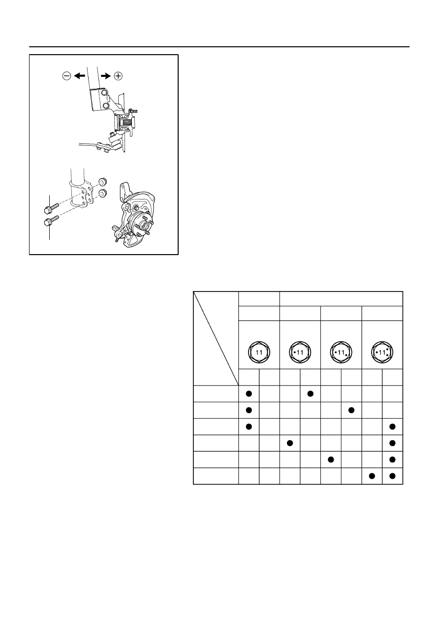
(e)
Adjust the camber by pushing or pulling the lower side of
the shock absorber in the direction in which the camber
adjustment is required.
(f)
Tighten the nuts.
Torque: 210 N
⋅
m (2,141 kgf
⋅
cm, 155 ft
⋅
lbf)
NOTICE:
When installing nut, stop the bolt from rotating and torque
the nut.
(g)
Install the front wheel.
Torque: 103 N·m (1,050 kgf·cm, 76 ft·lbf)
(h)
Check the camber.
HINT:
Try to adjust the camber to the center of the specified val-
ue.
Adjusting value for the set bolts is 6’ – 30’ (0.1
°
– 0.5
°
).
If the camber is not within the specified value, using the follow-
ing table, estimate how much additional camber adjustment will
be required, and select the camber adjusting bolt.
NOTICE:
Tighten the adjusting bolt with a washer and a new nut.
(i)
Do the steps mentioned above again. At step (b), replace
1 or 2 selected bolts.
HINT:
When replacing the 2 bolts, replace 1 bolt for each time.
2601F–02
F40136
F40137
C65925
C93871
–
FRONT SUSPENSION
FRONT SHOCK ABSORBER WITH COIL SPRING
26–9
1921
Author:
Date:
2002 CAMRY REPAIR MANUAL (RM881U)
FRONT SHOCK ABSORBER WITH COIL SPRING
OVERHAUL
HINT:
COMPONENTS: See page
26–3
1.
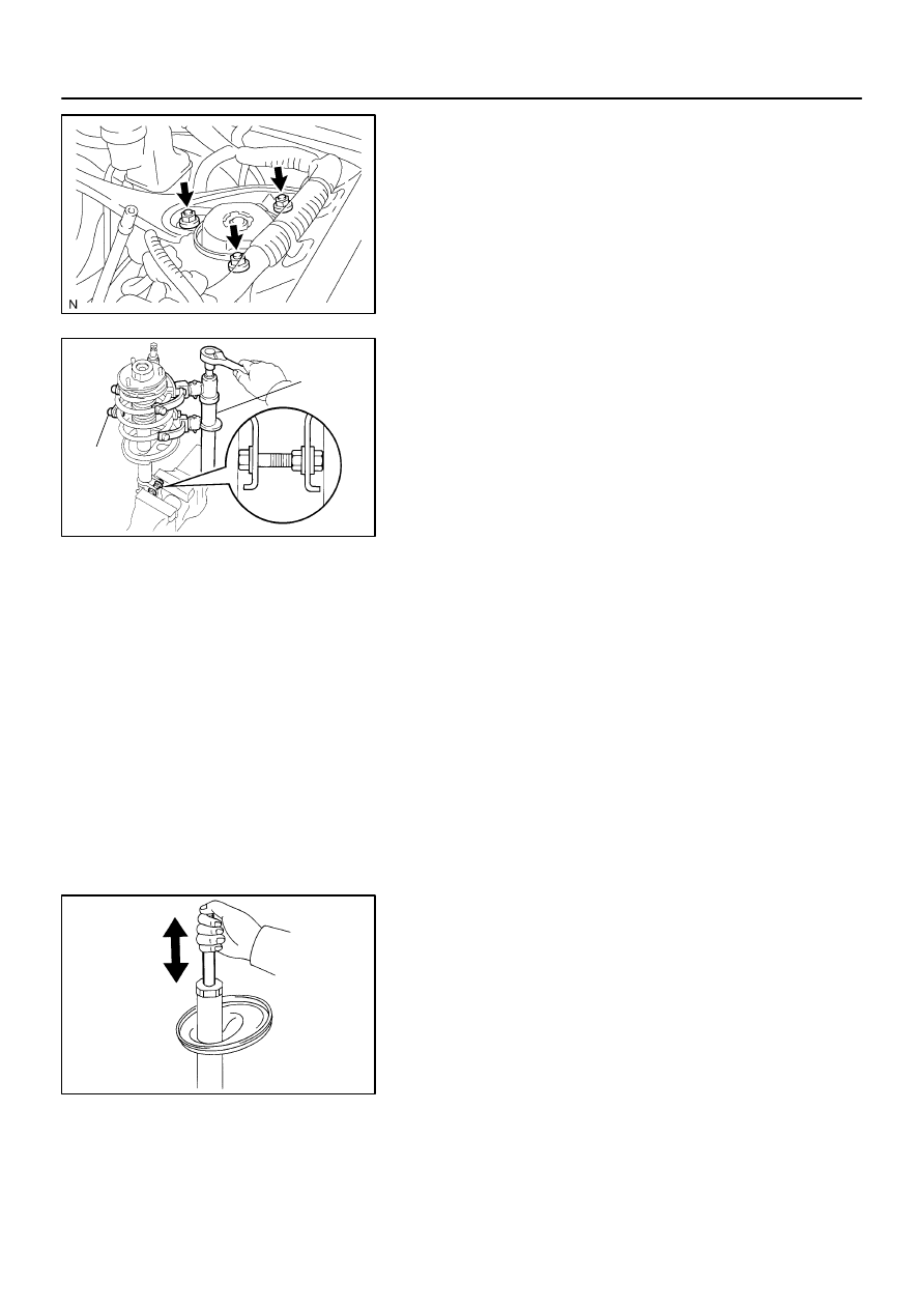
REMOVE FRONT WHEEL
2.
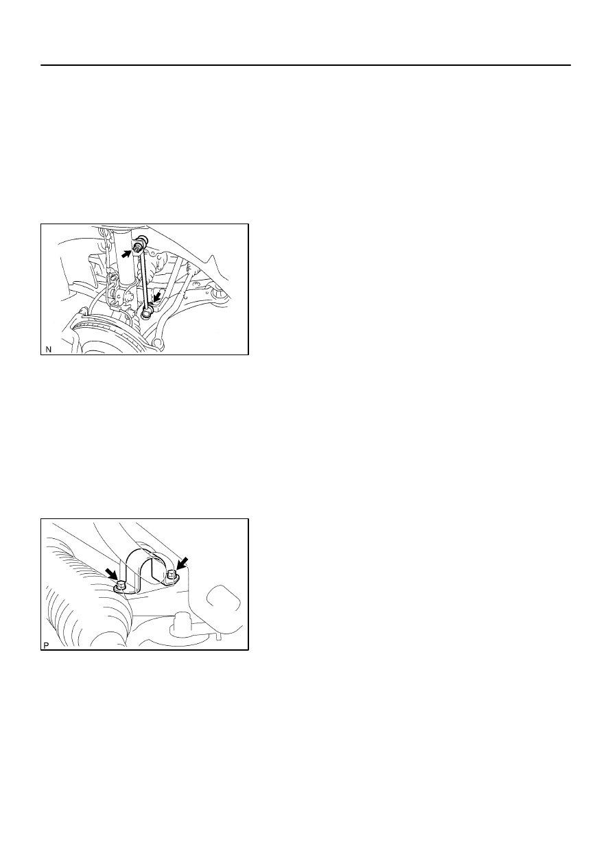
DISCONNECT FRONT STABILIZER LINK ASSY LH
(a)
Remove the nut and disconnect the front stabilizer link
assy LH from the shock absorber assy front LH.
HINT:
If the ball joint turns together with the nut, use a hexagon (6 mm)
wrench to hold the stud.
3.
REMOVE FRONT SHOCK ABSORBER WITH COIL
SPRING
(a)
Loosen the lock nut.
NOTICE:
Do not loosen except for the case with disassembling
the shock absorber assy front LH with coil spring.
Do not remove the lock nut.
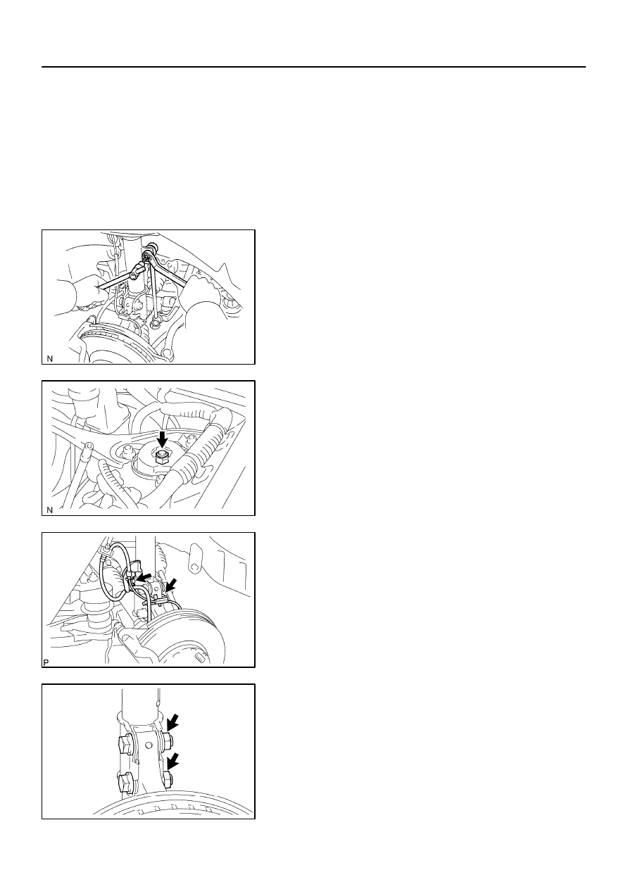
(b)
w/ ABS:
Remove the bolt, disconnect the front flexible hose No. 1
and speed sensor front LH.
(c)
w/o ABS:
Remove the bolt, disconnect the front flexible hose No. 1.
(d)
Remove the 2 nuts and 2 bolts on the lower side of front
shock absorber with coil spring.
NOTICE:
When removing bolt, stop the bolt from rotating and loosen
the nut.
F40140
F03956
SST
SST
W03646
26–10
–
FRONT SUSPENSION
FRONT SHOCK ABSORBER WITH COIL SPRING
1922
Author:
Date:
2002 CAMRY REPAIR MANUAL (RM881U)
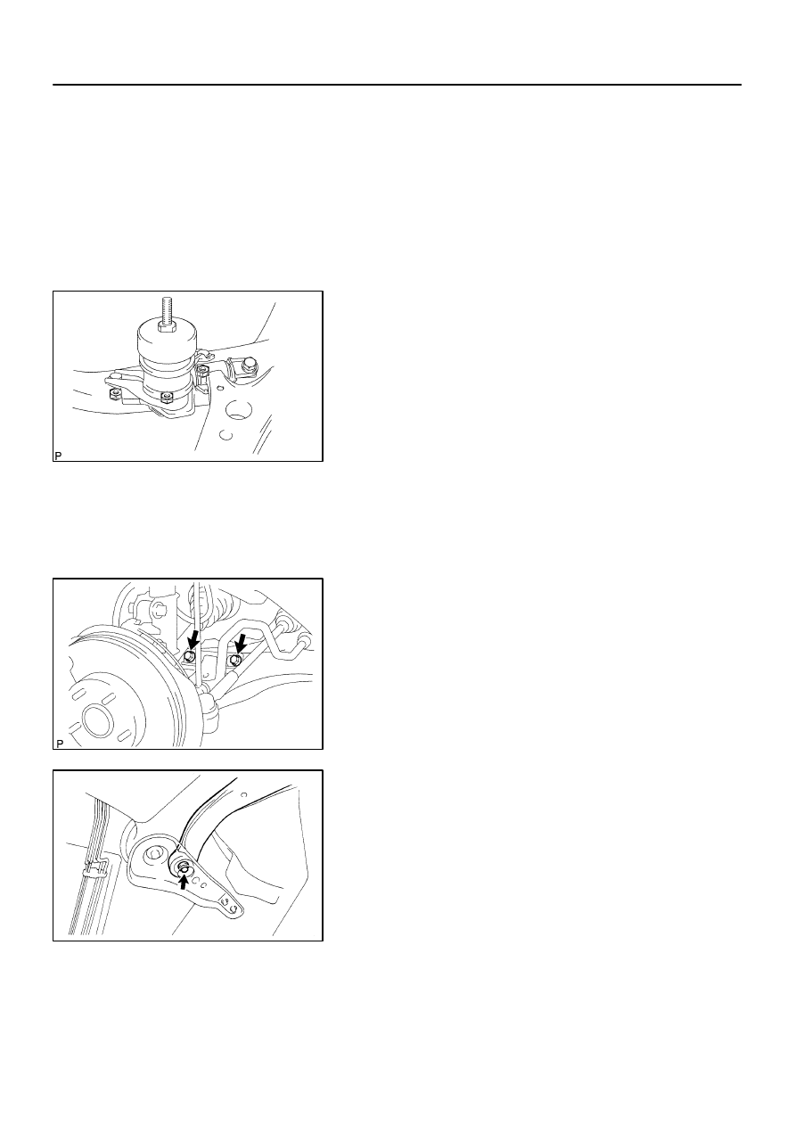
(e)
Remove the 3 nuts on the upper side of the front shock
absorber with coil spring.
(f)
Remove the front shock absorber with the coil spring.
NOTICE:
Be careful not to drop the 2 washers in the case that there
is front suspension upper brace center.
4.
FIX FRONT SHOCK ABSORBER WITH COIL SPRING
(a)
Install 2 nuts and a bolt to the bracket at the lower side of
the front shock absorber with coil spring and secure it in
a vise.
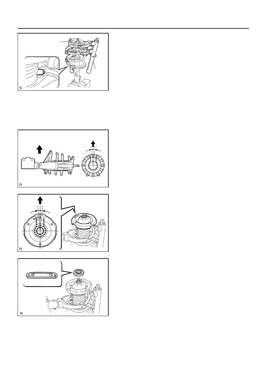
5.
REMOVE SHOCK ABSORBER ASSY FRONT LH
(a)
Using SST, compress the front coil spring LH.
SST
09727–30021
NOTICE:
Do not use an impact wrench. It will damage the SST.
HINT:
Use 2 of the same type of SST.
(b)
Remove the front suspension support sub–assy LH, front suspension support bearing LH, front coil
spring seat upper LH, front coil spring insulator upper LH, front coil spring LH, front spring bumper LH
and front coil spring insulator upper LH.
6.
INSPECT SHOCK ABSORBER ASSY FRONT LH
(a)
Compress and extend the shock absorber rod and check
that there is no abnormal resistance or unusual sound
during operation.
If there is any abnormality, replace the shock absorber assy
front LH with a new one.
NOTICE:
When disposing of the shock absorber assy front LH, see
DISPOSAL on page
26–14
.
7.
INSTALL SHOCK ABSORBER ASSY FRONT LH
(a)
Install the front coil spring insulator lower LH onto the
shock absorber assy front LH.
(b)
Install the front spring bumper LH to the piston rod.
F40160
SST
SST
F40168
Outside
Outside
5
5
F40161
5
5
Outside
F40162
–
FRONT SUSPENSION
FRONT SHOCK ABSORBER WITH COIL SPRING
26–11
1923
Author:
Date:
2002 CAMRY REPAIR MANUAL (RM881U)
(c)
Using SST, compress the front coil spring LH.
SST
09727–30021
NOTICE:
Do not use an impact wrench. It will damage the SST.
HINT:
Use 2 of the same type of SST.
(d)
Install the front coil spring LH to the shock absorber assy
front LH.
HINT:
Fit the lower end of the front coil spring LH into the gap of the
spring lower seat.
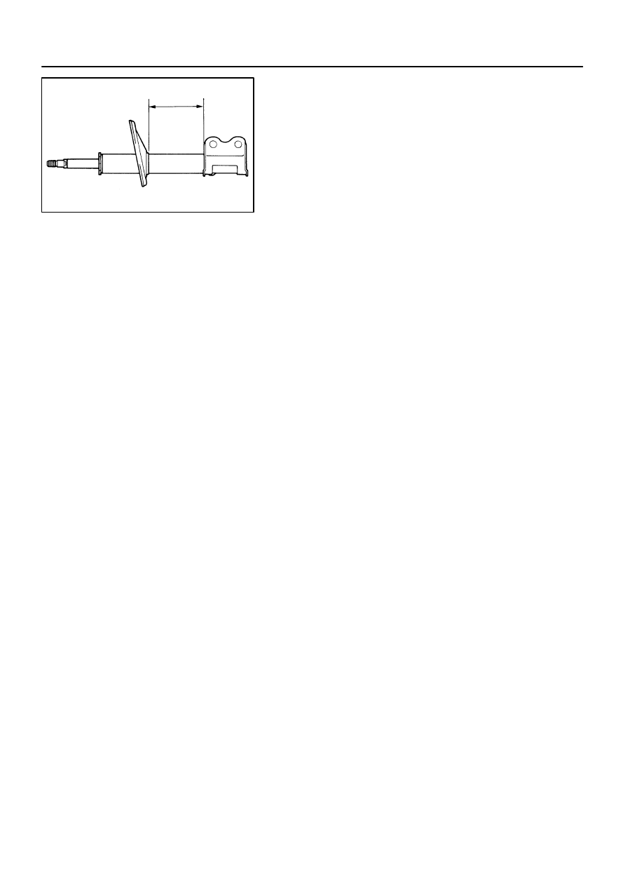
(e)
Install the front coil spring insulator upper LH as shown in
the illustration.
(f)
Install the front coil spring seat upper LH to the shock ab-
sorber assy front LH with the mark facing to the outside
of the vehicle.
(g)
Install a new front suspension support bearing LH.
F40169
Outside
Outside
F40140
C93871
F40137
C65925
26–12
–
FRONT SUSPENSION
FRONT SHOCK ABSORBER WITH COIL SPRING
1924
Author:
Date:
2002 CAMRY REPAIR MANUAL (RM881U)
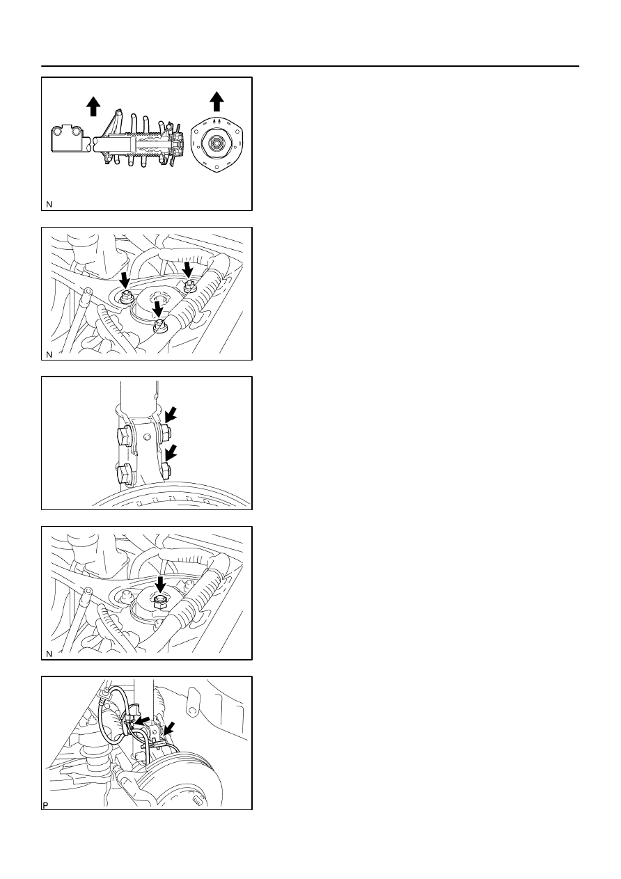
(h)
Install the front suspension support sub–assy LH with the
mark facing to the outside of the vehicle.
(i)
Temporarily tighten the new lock nut.
8.
INSTALL FRONT SHOCK ABSORBER WITH COIL
SPRING
(a)
Install the front shock absorber with coil spring as shown
in the illustration.
(b)
Install the 3 nuts to the upper side of front shock absorber
with coil spring.
Torque: 80 N
⋅
m (816 kgf
⋅
cm, 59 ft
⋅
lbf)
NOTICE:
Be careful not to drop the 2 washers in the case that there
is front suspension upper brace center.
(c)
Install the 2 bolts and 2 nuts to the lower side of front
shock absorber with coil spring.
Torque: 210 N
⋅
m (2,141 kgf
⋅
cm, 155 ft
⋅
lbf)
NOTICE:
When installing bolt, stop the bolt from rotating and torque
the nut.
(d)
Fully tighten the lock nut.
Torque: 49 N
⋅
m (500 kgf
⋅
cm, 36 ft
⋅
lbf)
(e)
w/ ABS:
Install the front flexible hose No. 1 and speed sensor front
LH with the bolt.
Torque: 18.8 N
⋅
m (192 kgf
⋅
cm, 14 ft
⋅
lbf)
(f)
w/o ABS:
Install the front flexible hose No. 1 with the bolt.
Torque: 18.8 N
⋅
m (192 kgf
⋅
cm, 14 ft
⋅
lbf)
F40136
–
FRONT SUSPENSION
FRONT SHOCK ABSORBER WITH COIL SPRING
26–13
1925
Author:
Date:
2002 CAMRY REPAIR MANUAL (RM881U)
9.
INSTALL FRONT STABILIZER LINK ASSY LH
(a)
Install the front stabilizer link assy LH with the nut.
Torque: 74 N
⋅
m (755 kgf
⋅
cm, 55 ft
⋅
lbf)
HINT:
If the ball joint turns together with the nut, use a hexagon (6 mm)
wrench to hold the stud.
10.
INSTALL FRONT WHEEL
Torque: 103 N
⋅
m (1,050 kgf
⋅
cm, 76 ft
⋅
lbf)
11.
INSPECT AND ADJUST FRONT WHEEL ALIGNMENT(See page
26–5
)
2601G–02
N00204
26–14
–
FRONT SUSPENSION
FRONT SHOCK ABSORBER WITH COIL SPRING
1926
Author:
Date:
2002 CAMRY REPAIR MANUAL (RM881U)
DISPOSAL
HINT:
Dispose the RH side by the same procedures with the LH side.
1.
DISPOSE SHOCK ABSORBER ASSY FRONT LH
(a)
Fully extend the shock absorber rod.
(b)
Using a drill, make a hole in the cylinder as shown in the
illustration to discharge the gas inside.
CAUTION:
When drilling, chips may fly out, work carefully.
The gas is colorless, odorless and non–poisonous.
2601H–02
C83387
C91606
F02227
–
FRONT SUSPENSION
FRONT SUSPENSION ARM SUB–ASSY LOWER NO.1
LH
26–15
1927
Author:
Date:
2002 CAMRY REPAIR MANUAL (RM881U)
FRONT SUSPENSION ARM SUB–ASSY LOWER NO.1 LH
REPLACEMENT
HINT:
COMPONENTS: See page
26–3
.
1.
REMOVE ENGINE ASSEMBLY WITH TRANSAXLE(1MZ–FE ENGINE TYPE)(See page
14–155
)
2.
REMOVE ENGINE ASSEMBLY WITH TRANSAXLE(2AZ–FE ENGINE TYPE)(See page
14–22
)
3.
REMOVE TRANSVERSE ENGINE ENGINE
MOUNTING INSULATOR(A/T TRANSAXLE)
(a)
Remove the 3 nuts and transverse engine engine mount-
ing insulator.
4.
REMOVE TRANSVERSE ENGINE ENGINE MOUNTING INSULATOR(M/T TRANSAXLE)
(a)
Remove the 3 nuts and transverse engine engine mounting insulator.
(b)
Remove the 4 bolts and bracket from the manual transmission.
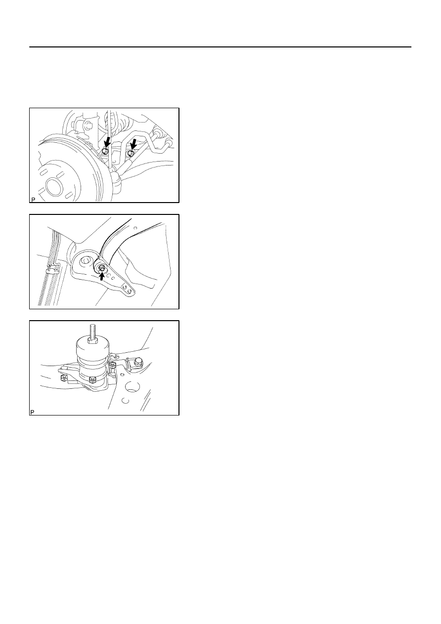
5.
REMOVE FRONT SUSPENSION ARM SUB–ASSY
LOWER NO.1 LH
(a)
Remove the 2 bolts on the front side of the front suspen-
sion arm sub–assy lower No. 1 LH.
(b)
Remove the bolt and nut on the rear side of the front sus-
pension arm sub–assy lower No. 1 LH.
(c)
Remove the front suspension arm sub–assy lower No. 1
LH.
(d)
Remove the front lower arm bush stopper from the front
suspension arm sub–assy lower No. 1 LH.
C91606
F02227
C83387
26–16
–
FRONT SUSPENSION
FRONT SUSPENSION ARM SUB–ASSY LOWER NO.1
LH
1928
Author:
Date:
2002 CAMRY REPAIR MANUAL (RM881U)
6.
INSTALL FRONT SUSPENSION ARM SUB–ASSY
LOWER NO.1 LH
(a)
Install the front lower arm bush stopper to the front sus-
pension arm sub–assy lower No. 1 LH.
(b)
Install the front suspension arm sub–assy lower No. 1 LH
with the 2 bolts to the front side.
Torque: 200 N
⋅
m (2,039 kgf
⋅
cm, 148 ft
⋅
lbf)
(c)
Install the front suspension arm sub–assy lower No. 1 LH
with the bolt and nut to the rear side.
Torque: 206 N
⋅
m (2,101 kgf
⋅
cm, 152 ft
⋅
lbf)
7.
INSTALL TRANSVERSE ENGINE ENGINE MOUNTING
INSULATOR(A/T TRANSAXLE)
(a)
Install the transverse engine engine mounting insulator
with the 3 nuts.
Torque: 87 N
⋅
m (887 kgf
⋅
cm, 64 ft
⋅
lbf)
8.
INSTALL TRANSVERSE ENGINE ENGINE MOUNTING INSULATOR(M/T TRANSAXLE)
(a)
Install the bracket with the 4 bolts to the manual transmission.
Torque: 64 N
⋅
m (653 kgf
⋅
cm, 47 ft
⋅
lbf)
(b)
Install the transverse engine engine mounting insulator with the 3 nuts.
Torque: 87 N
⋅
m (887 kgf
⋅
cm, 64 ft
⋅
lbf)
9.
INSTALL ENGINE ASSEMBLY WITH TRANSAXLE(2AZ–FE ENGINE TYPE)(Seepage
14–22
)
10.
INSTALL ENGINE ASSEMBLY WITH TRANSAXLE(1MZ–FE ENGINE TYPE)(Seepage
14–155
)
2601I–02
ZX1712
–
FRONT SUSPENSION
LOWER BALL JOINT ASSY FRONT LH
26–17
1929
Author:
Date:
2002 CAMRY REPAIR MANUAL (RM881U)
LOWER BALL JOINT ASSY FRONT LH
REPLACEMENT
HINT:
COMPONENTS: See page
26–3
.
1.
REMOVE FRONT WHEEL
2.
REMOVE FRONT AXLE HUB LH NUT
(See page
30–8
)
SST
09930–00010
3.
DISCONNECT SPEED SENSOR FRONT LH(W/ ABS)
(See page
30–8
)
4.
DISCONNECT FRONT DISC BRAKE CALIPER ASSY LH(See page
30–21
)
5.
REMOVE FRONT DISC
6.
DISCONNECT TIE ROD ASSY LH
(See page
30–8
)
SST
09628–62011
7.
DISCONNECT FRONT SUSPENSION ARM SUB–ASSY LOWER NO.1 LH
(See page
30–8
)
8.
REMOVE FRONT AXLE ASSY LH(See page
30–21
)
9.
REMOVE LOWER BALL JOINT ASSY FRONT LH
(See page
30–21
)
SST
09628–62011
10.
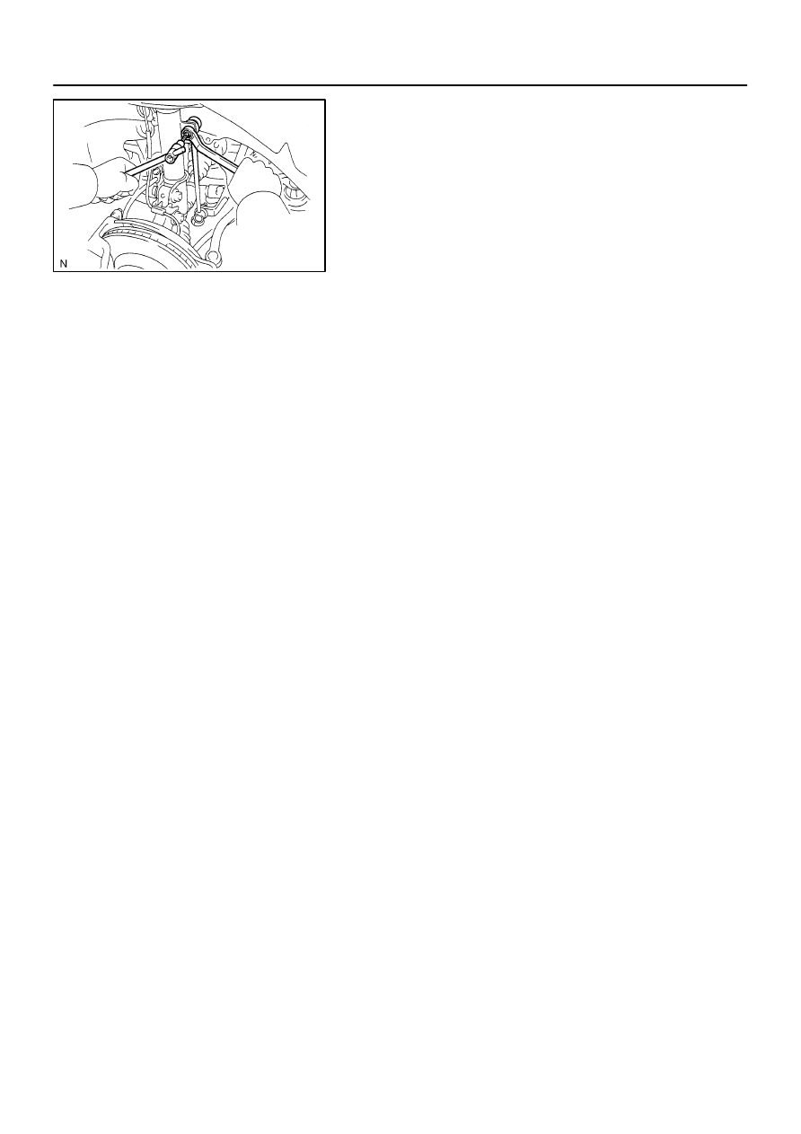
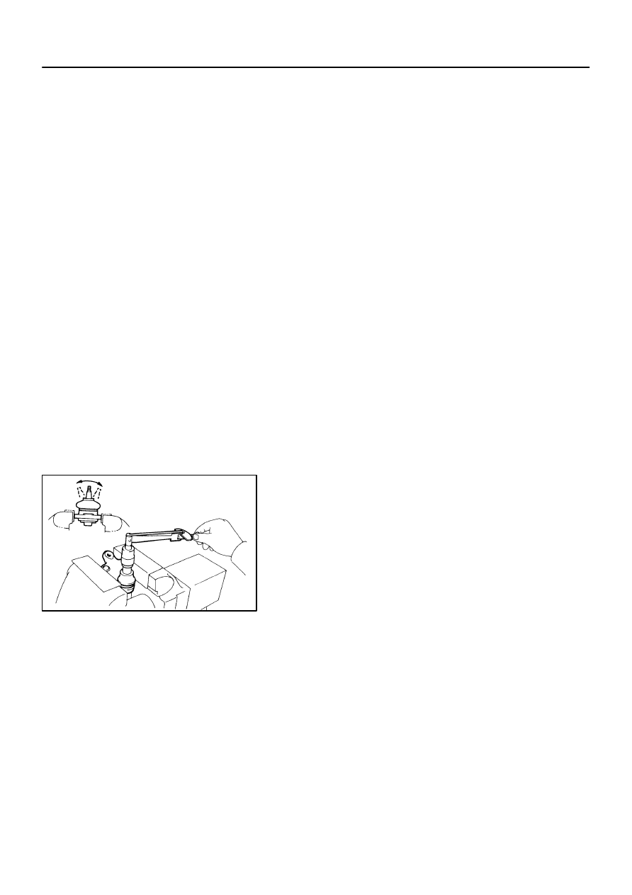
INSPECT LOWER BALL JOINT ASSY FRONT LH
(a)
As shown in the illustration, flip the ball joint stud back and
forth 5 times, before installing the nut.
(b)
Using a torque wrench, turn the nut continuously at a rate
of 3 – 5 seconds per 1 turn and take the torque reading
on the 5th turn.
Turning torque:
0.98 – 3.43 N·m (10 – 35 kgf·cm, 8.7 – 30 in.·lbf)
11.
INSTALL LOWER BALL JOINT ASSY FRONT LH
(See page
30–21
)
12.
INSTALL FRONT AXLE ASSY LH(See page
30–21
)
13.
INSTALL FRONT SUSPENSION ARM SUB–ASSY LOWER NO.1 LH
(See page
30–8
)
14.
INSTALL TIE ROD ASSY LH
(See page
30–8
)
15.
INSTALL FRONT DISC
16.
INSTALL FRONT DISC BRAKE CALIPER ASSY LH(See page
30–21
)
17.
INSTALL SPEED SENSOR FRONT LH(W/ ABS)
(See page
30–8
)
18.
INSTALL FRONT AXLE HUB LH NUT
(See page
30–8
)

26–18
–
FRONT SUSPENSION
LOWER BALL JOINT ASSY FRONT LH
1930
Author:
Date:
2002 CAMRY REPAIR MANUAL (RM881U)
19.
INSTALL FRONT WHEEL
Torque: 103 N
⋅
m (1,050 kgf
⋅
cm, 76 ft
⋅
lbf)
20.
INSPECT AND ADJUST FRONT WHEEL ALIGNMENT(See page
26–5
)
21.
CHECK ABS SPEED SENSOR SIGNAL(W/ ABS)
w/ VSC (See page
05–452
)
w/o VSC (BOSCH MADE) (See page
05–363
)
w/o VSC (DENSO MADE) (See page
05–404
)
2601J–02
F40143
C91607
–
FRONT SUSPENSION
STABILIZER BAR FRONT
26–19
1931
Author:
Date:
2002 CAMRY REPAIR MANUAL (RM881U)
STABILIZER BAR FRONT
REPLACEMENT
HINT:
COMPONENTS: See page
26–3
.
1.
REMOVE FRONT WHEEL
2.
REMOVE FRONT STABILIZER LINK ASSY LH
(a)
Remove the 2 nuts and front stabilizer link assy LH.
HINT:
If the ball joint turns together with the nut, use a hexagon (6 mm)
wrench to hold the stud.
3.
REMOVE FRONT STABILIZER LINK ASSY RH
HINT:
Remove the RH side by the same procedures with the LH side.
4.
REMOVE FRONT SUSPENSION MEMBER DYNAMIC DAMPER(EXCEPT 1MZ–FE ENGINE TYPE)
(a)
Remove the 2 bolts and front suspension member dynamic damper from the front frame assy.
5.
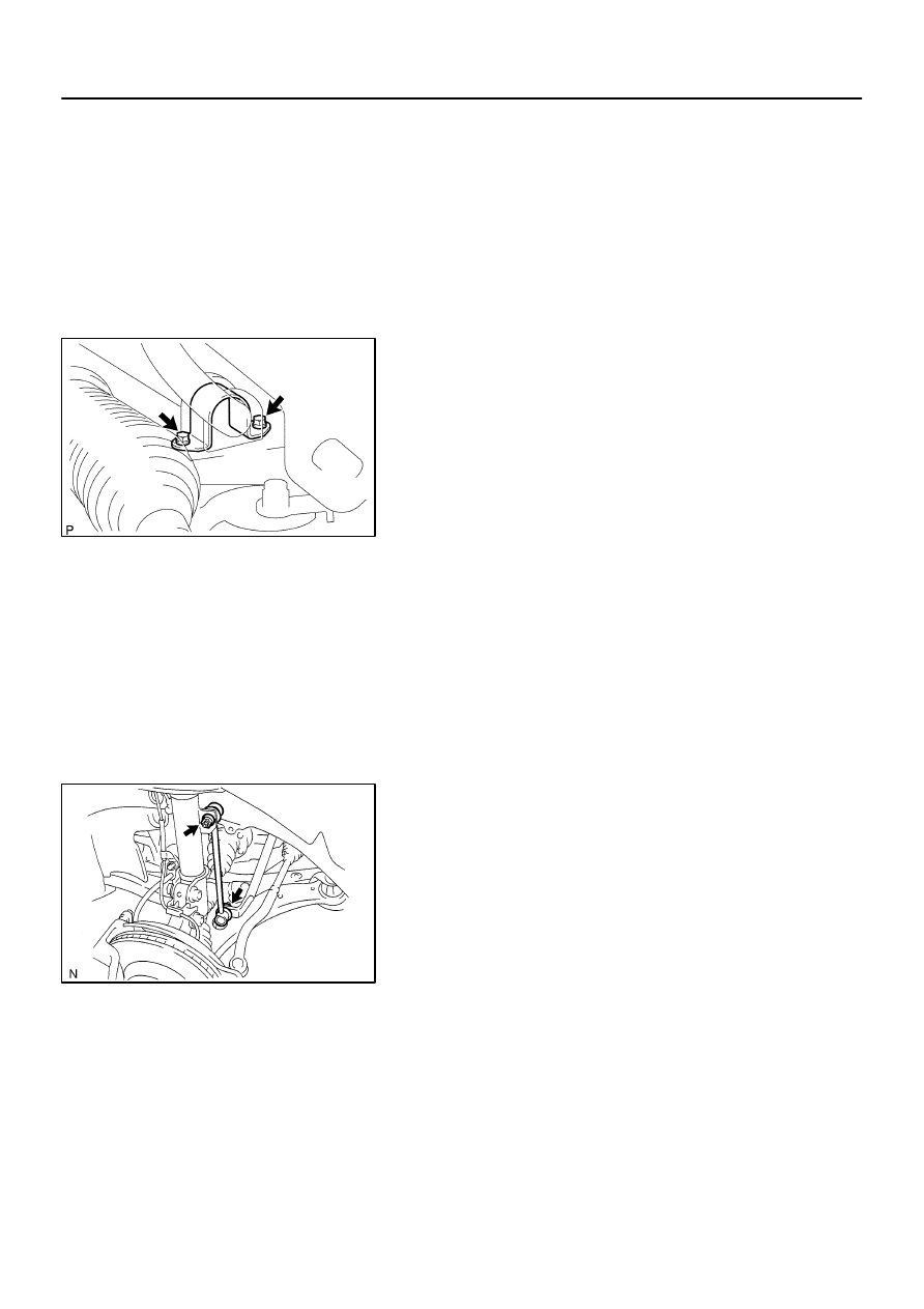
REMOVE FRONT STABILIZER BRACKET NO.1 LH
(a)
Remove the 2 bolts and 2 front stabilizer brackets No. 1
LH.
6.
REMOVE FRONT STABILIZER BRACKET NO.1 RH
HINT:
Remove the RH side by the same procedures with the LH side.
7.
DISCONNECT TIE ROD ASSY LH
(See page
30–8
)
SST
09628–62011
C66721
C81547
F40197
Inner side
Rear
side
26–20
–
FRONT SUSPENSION
STABILIZER BAR FRONT
1932
Author:
Date:
2002 CAMRY REPAIR MANUAL (RM881U)
8.
DISCONNECT TIE ROD ASSY RH
SST
09628–62011
HINT:
Separate the RH side by the same procedures with the LH side.
9.
DISCONNECT STEERING GEAR OUTLET RETURN TUBE
(See page
51–29
)
SST
09023–00100
10.
DISCONNECT PRESSURE FEED TUBE ASSY
(See page
51–29
)
SST
09023–00100
11.
DISCONNECT STEERING INTERMEDIATE SHAFT SUB–ASSY
(See page
51–29
)
12.
REMOVE RACK & PINION POWER STEERING GEAR ASSY
(See page
51–29
)
13.
REMOVE STABILIZER BAR FRONT
14.
REMOVE FRONT STABILIZER BAR BUSH NO.1
15.
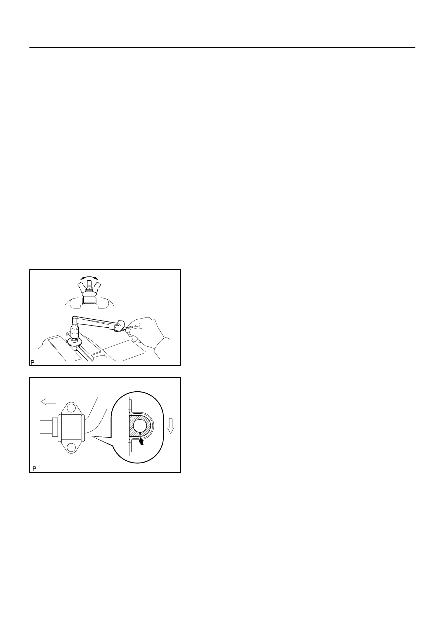
INSPECT FRONT STABILIZER LINK ASSY LH
(a)
As shown in the illustration, flip the ball joint stud back and
forth 5 times, before installing the nut.
(b)
Using a torque wrench, turn the nut continuously at a rate
of 2 – 4 seconds per 1 turn and take the torque reading
on the 5th turn.
Turning torque:
0.05 – 1.96 N·m (0.5 – 20 kgf·cm, 0.4 – 17.4 in.·lbf)
16.
INSTALL FRONT STABILIZER BAR BUSH NO.1
HINT:
Install the bushing to the inner side of the bushing stopper on
the stabilizer bar.
17.
INSTALL STABILIZER BAR FRONT
18.
INSTALL RACK & PINION POWER STEERING GEAR ASSY
(See page
51–29
)
19.
INSTALL STEERING INTERMEDIATE SHAFT SUB–ASSY
(See page
51–29
)
20.
INSTALL PRESSURE FEED TUBE ASSY
(See page
51–29
)
SST
09023–00100
C91607
F40143
–
FRONT SUSPENSION
STABILIZER BAR FRONT
26–21
1933
Author:
Date:
2002 CAMRY REPAIR MANUAL (RM881U)
21.
INSTALL STEERING GEAR OUTLET RETURN TUBE
(See page
51–29
)
SST
09023–00100
22.
INSTALL TIE ROD ASSY LH
(See page
30–8
)
23.
INSTALL TIE ROD ASSY RH
HINT:
Install the RH side by the same procedures with the LH side.
24.
INSTALL FRONT STABILIZER BRACKET NO.1 LH
(a)
Install the 2 front stabilizer brackets No. 1 LH with the 2
bolts.
Torque: 19 N
⋅
m (194 kgf
⋅
cm, 14 ft
⋅
lbf)
25.
INSTALL FRONT STABILIZER BRACKET NO.1 RH
HINT:
Install the RH side by the same procedures with the LH side.
26.
INSTALL FRONT SUSPENSION MEMBER DYNAMIC DAMPER(EXCEPT 1MZ–FE ENGINE TYPE)
(a)
Install the front suspension member dynamic damper with 2 bolts to the front frame assy.
Torque: 29 N
⋅
m (296 kgf
⋅
cm, 21 ft
⋅
lbf)
27.
INSTALL FRONT STABILIZER LINK ASSY LH
(a)
Install the front stabilizer link assy LH with the 2 nuts.
Torque: 74 N
⋅
m (755 kgf
⋅
cm, 55 ft
⋅
lbf)
HINT:
If the ball joint turns together with the nut, use a hexagon (6 mm)
wrench to hold the stud.
28.
INSTALL FRONT STABILIZER LINK ASSY RH
HINT:
Install the RH side by the same procedures with the LH side.
29.
INSTALL FRONT WHEEL
Torque: 103 N
⋅
m (1,050 kgf
⋅
cm, 76 ft
⋅
lbf)
30.
BLEED POWER STEERING FLUID(See page
51–3
)
31.
CHECK POWERSTEERING FLUID LEAKAGE
32.
INSPECT AND ADJUST FRONT WHEEL ALIGNMENT(See page
26–5
)
Wyszukiwarka
Podobne podstrony:
26 Front Suspension
26 Front Suspension
26 Front Suspension
26 Front Suspension
FRONT SUSPENSION
09 front suspension
Jag front suspension xk 120,xk 140,xk 150;mk VII,mk VIII,mk IX
M32c Front Suspension
Front suspension strut
g3 front suspension
13 Front Suspension
ARTICLE SUSPENSION STRUT FRONT REPLACE INSTALL
ARTICLE SUSPENSION STRUT FRONT DISASSEMBLE REASSEMBLE
11 Front Wheel Suspension Steering
ARTICLE SUSPENSION LOWER CONTROL ARM FRONT SERVICE
więcej podobnych podstron