
FRONT
SUSPENSION
Return To Main Table of Contents
GENERAL . . . . . . . . . . . . . . . . . . . . . . . . . . . . . . . . . . . . . . . . . . . . . .
STRUT ASSEMBLY . . . . . . . . . . . . . . . . . . . . . . . . . . . . . . . . . . . .
LOWER ARM . . . . . . . . . . . . . . . . . . . . . . . . . . . . . . . . . . . . . . . . . .
STABILIZER BAR . . . . . . . . . . . . . . . . . . . . . . . . . . . . . . . . . . . . . .
CENTER MEMBER . . . . . . . . . . . . . . . . . . . . . . . . . . . . . . . . . . . .
WHEEL AND TIRE . . . . . . . . . . . . . . . . . . . . . . . . . . . . . . . . . . . .
GENERAL
GENERAL
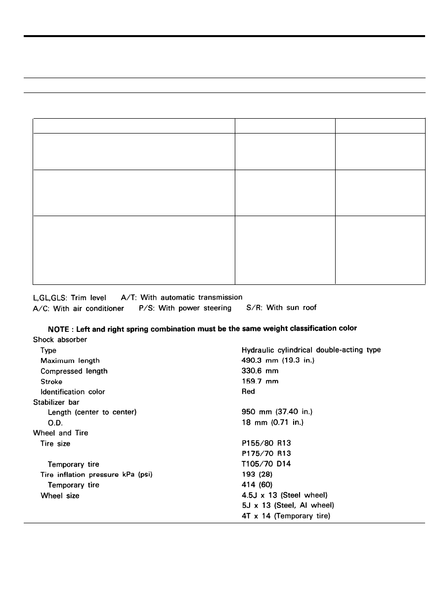
SPECIFICATIONS
Suspension system
Coil spring
Free height and identification color
Model
L
GL
GLS
Macpherson strut with coil spring
Free height mm (in.)
Identification color
347.3 (13.67)
Yellow 2 lines
GL+A/C
GL+A/T
L+A/C
GLS+A/C
GLS+A/T
GLS+P/S
GLS+A/T+P/S
GLS+S/R
GLS+A/T+S/R
GLS+P/S+S/R
L+A/T
GL+A/T+A/C
L+A/T+A/C
GLS+A/T+A/C
GLS+A/C+P/S GLS+A/C+S/R
GLS+A/T+A/C+P/S
GLS+A/C+P/S+S/R
GLS+A/T+A/C+S/R
GLS+A/T+P/S+S/R
GLS+A/T+A/C+P/S+S/R
355.3 (13.98)
Green 2 lines
363.3 (14.30)
Blue 2 lines
5 4 - 2

GENERAL
SERVICE STANDARD
Standard value
Toe
Camber
Caster
King pin inclination angle
King pin offset
Max. camber angle difference between LH and RH
Steering angle
Inside wheel
Outside wheel
Wheel runout
Radial mm (in.)
Axial mm (in.)
4 mm in -2 mm out
0° ± 30’
1°2’ ± 30’ (Manual)
12°59’
- 3 . 5 m m
30’
1°40’ ± 30’ (Power)
37°24’ ± 1°30’
31°31’
[Steel wheel]
0.7 (0.028)
1.0 (0.039)
[Aluminum wheel]
0.3 (0.012)
0.3 (0.012)
TIGHTENING TORQUE
Nm
kg.cm
Ib.ft
Strut mounting self locking nut
Upper strut installation nut
Knuckle to strut assembly
Lower arm ball joint to knuckle
Tie rod end ball joint to knuckle
Ball joint to lower arm assembly
Lower arm mounting shaft mounting nut
Lower arm mounting shaft bolt (to floor)
Lower arm mounting bracket bolt (to floor)
Stabilizer bar lower/upper bracket mounting bolt
Stabilizer bar to lower arm mounting bushing bolt
Drive shaft nut
Wheel nut
3 9 - 4 9
4 0 0 - 5 0 0
2 9 - 3 6
1 5 - 2 0
1 5 0 - 2 0 0
1 1 - 1 4
7 4 - 8 8
7 5 0 - 9 0 0
5 4 - 6 5
5 9 - 7 1
6 0 0 - 7 2 0
4 3 - 5 2
1 5 - 3 3
1 5 0 - 3 4 0
1 1 - 2 5
9 3 - 1 1 8
9 5 0 - 1 2 0 0
6 9 - 8 7
9 3 - 1 1 8
9 5 0 - 1 2 0 0
6 9 - 8 7
1 5 7 - 1 8 7
1 6 0 0 - 1 9 0 0
1 1 6 - 1 3 7
5 9 - 7 8
6 0 0 - 8 0 0
4 3 - 5 8
1 7 - 2 5
1 7 0 - 2 6 0
12-19
1 9 6 - 2 5 5
8 8 - 1 0 8
2 0 0 0 - 2 6 0 0
1 4 5 - 1 8 8
9 0 0 - 1 1 0 0
6 5 - 8 0
LUBRICANTS
Inside surface and lip of ball joint dust cover
Multipurpose grease
SAE J310, NLGI No.2
As required
Strut insulator bearing
Chassis grease
SAE J310, NLGI No.0
As required
5 4 - 3
GENERAL
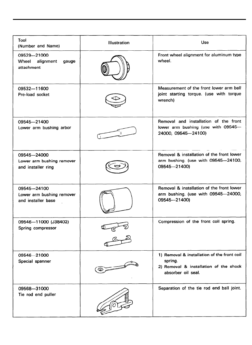
SPECIAL TOOLS
5 4 - 4
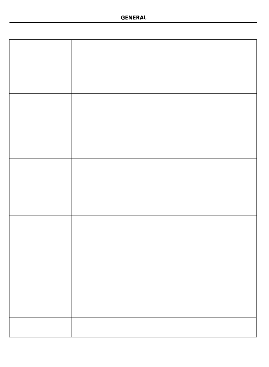
TROUBLESHOOTING
Symptom
Probable cause
Remedy
l-lard steering
improper front wheel alignment
Correct
Excessive turning resistance of lower arm ball
Replace
joint
Low tire pressure
Adjust
No power assist
Repair and replace
Poor return of steering
Improper front wheel alignment
Correct
wheel to center
Poor or rough ride
Improper front wheel alignment
Correct
Malfunctioning shock absorber
Repair or replace
Broken or worn stabilizer
Replace
Broken or worn coil spring
Replace
Worn lower arm bushing
Replace the lower arm assembly
Abnormal tire wear
Improper front wheel alignment
Correct
Improper tire pressure
Adjust
Malfunctioning shock absorber
Replace
Wandering
Improper front wheel alignment
Correct
Poor turning resistance of lower arm ball joint
Repair
Loose or worn lower arm bushing
Retighten or replace
Vehicle pulls to one side
Improper front wheel alignment
Correct
Excessive turning resistance of lower arm ball
Replace
joint
Broken or worn coil spring
Replace
Bent lower arm
Repair
Steering wheel shimmy
Improper front wheel alignment
Correct
Poor turning resistance of lower arm ball joint
Replace
Broken or worn stabilizer
Replace
Worn lower arm bushing
Replace
Malfunctioning shock absorber
Replace
Broken or worn coil spring
Replace
Bottoming
Broken or worn coil spring
Replace
Malfunctioning shock absorber
Replace
5 4 - 5
GENERAL
5 4 - 6
SERVICE ADJUSTMENT PROCEDURES
FRONT WHEEL ALIGNMENT
When using a wheel alignment tester to inspect front wheel
alignment, always position the car on a level surface and the
front wheels in the straight ahead position. Prior to inspection
make sure that the front suspension and steering system are in
normal operating condition and that wheels and tires are free
of deflection and tires inflated to specification.
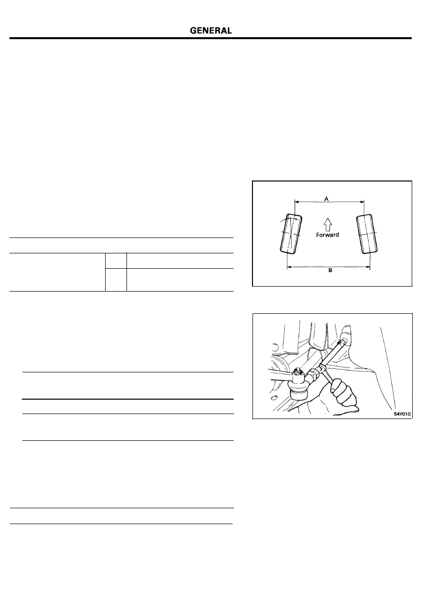
Toe-in
Toe-in (B-A or angle a) is adjusted by turning the tie rod
turn-buckles. Toe in on the left front wheel can be reduced by
turning the tie rod toward the rear of the car. Toe change is
achieved by turning the tie rods for the right and left wheels
simultaneously the same amount as follows:
Description
Toe changes mm (in.)/deg.
No. of turns of tie rod
½
6.5
(0.257)/39’
(Same amount for right
and left)
1
13.1 (0.514)/1°18’
CAUTION
1) Toe-in adjustment should be made by turning the right and
left tie rods the same amount.
2) When adjusting toe-in, loosen the outer bellows clip to
prevent twisting the bellows.
3) After the adjustment, firmly tighten the tie rod end lock
nuts and reinstall the bellows clip.
Toe (B-A) mm (in.) [Standard value] . . . . . . . . . . . . . . . . . . . . .
4
in-2 out (0.157 in-0.079 out)
Tie rod end lock nuts tightening torque . . . . . . . . . . . . . . . . .
49-54 Nm (500-550 kg.cm, 36-40 Ib.ft)
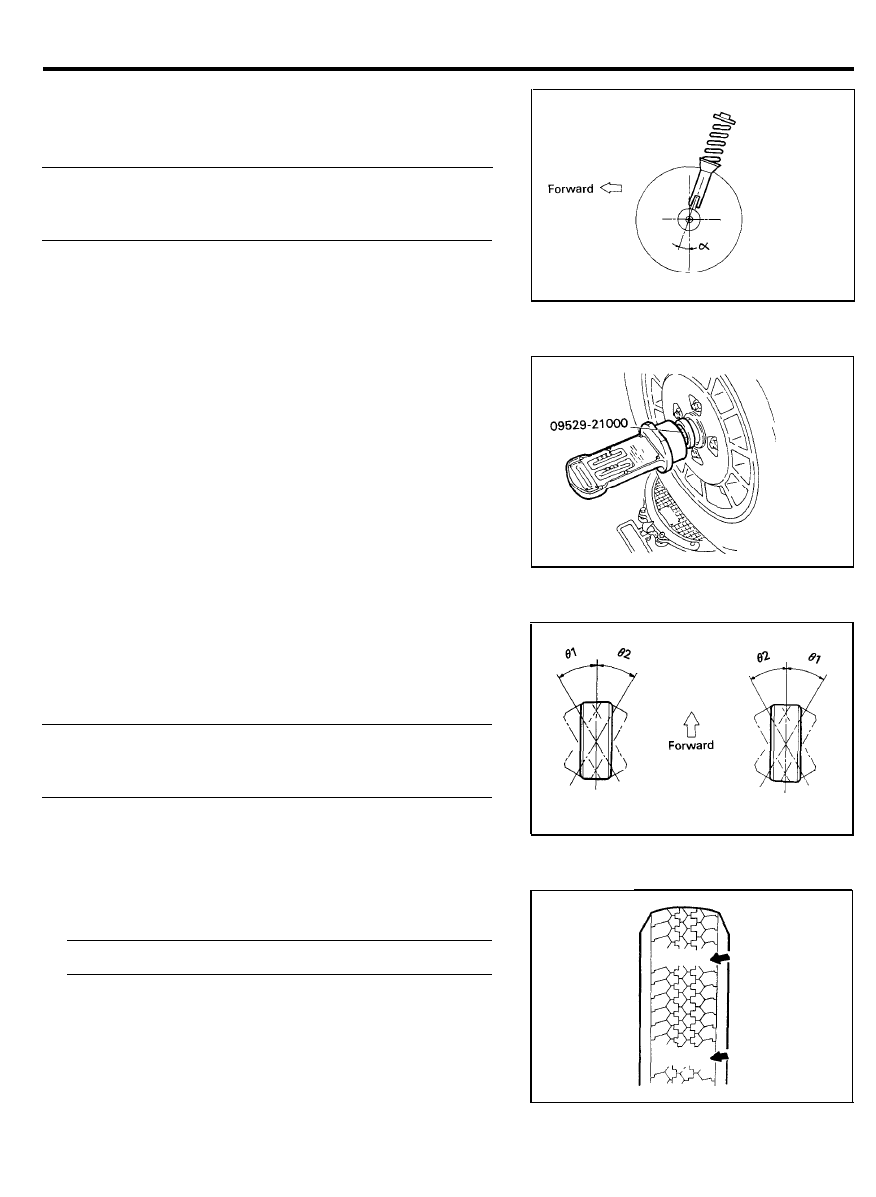
Camber
The steering knuckle which is integral with the strut assembly
is pre-adjusted to the specified camber at the factory and
requires no adjustment.
Camber [Standard value] . . . . . . . . . . . . . . . . . . . . . . . . . . . 0° ±
30’
5 4 - 7
GENERAL
Caster
Caster is pre-set at the factory and can not be adjusted. If caster
is not within standard value, replace the bent or damaged parts.
Caster [Standard value]
Manual steering . . . . . . . . . . . . . . . . . . . . . . . . . . . . . .
1°2’ ± 30’
Power steering.. . . . . . . . . . . . . . . . . . . . . . . . . . . . . .
1°40’ ± 30’
NOTE
1) The front suspension assembly must be free of worn, loose
or damaged parts prior to measuring front wheel
alignment.
2) Measure wheel alignment by using the Special Tool
( 0 9 5 2 9 - 2 1 0 0 0 ) .
3) Camber and caster are pre-set at the factory and cannot
be adjusted.
4) If camber and caster are not within specifications, replace
bent or damaged parts.
Steering Angle
Steering angle, as a rule, requires no adjustment. However, if
there is a difference in steering angle between the right and left
wheels, change the length of the right and left tie rods.
Steering angle [Standard value]
Inner wheel 81 . . . . . . . . . . . . . . . . . . . . . . . . . . . . 37°24’ ± 1°30’
Outer wheel 82 . . . . . . . . . . . . . . . . . . . . . . . . . . . . . . . . . . . . 31°31’
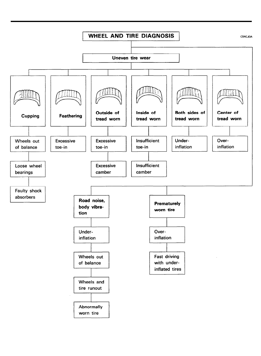
TIRE WEAR
1. Measure the tread depth of the tires.
Tread depth of tire [Limit] . . . . . . . . . . . . . 1.6 mm (0.06 in.)
2. If the remaining tread depth is less than the limit, replace
the tire.
NOTE
When the tread depth of the tires is reduced to 1.6 mm
(0.06 in.) or less, the wear indicators will appear.
5 4 - 8
GENERAL
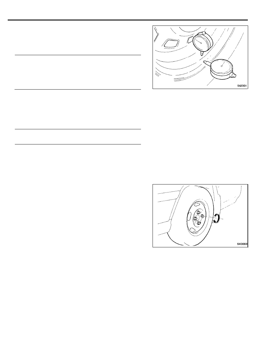
WHEEL RUNOUT
1. Jack up the vehicle and support it with jack stands.
2. Measure wheel runout with a dial indicator as illustrated.
3. Replace the wheel if wheel runout exceeds the limit.
Wheel runout [Limit]
Steel wheel
Aluminum type wheel
Radial 0.7 mm (0.028 in.)
Axial 1.0 mm (0.039 in.)
Radial 0.3 mm (0.012 in.)
Axial 0.3 mm (0.012 in.)
WHEEL NUT TIGHTENING
1. Tightening torque
Steel and aluminum alloy wheel
Specified torque . . . . . . . . . . . . . . . . . . . . . . . . . . . . . . . . . . . . . . . .
88-108 Nm (900-1,100 kg.cm, 65-80 Ib.ft)
CAUTION
When using impact-wrench, tightening torque should be
controlled certainly.
2. Tightening order
Go around the wheel tightening every other nut until they
are all tight.
Then double-check each nut for tightness.
5 4 - 9
STRUT ASSEMBLY
STRUT ASSEMBLY
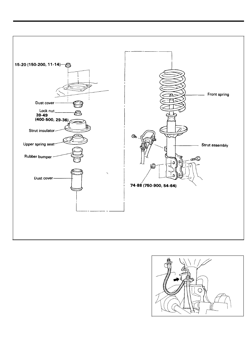
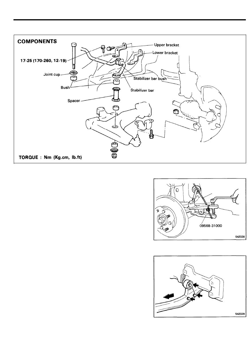
COMPONENTS
TORQUE : Nm (kg.cm, Ib.ft)
REMOVAL
1.
Raise the front of the vehicle and mount it on a jack stand.
2. Remove the wheel and tire.
3. Detach the brake hose and tube bracket from the strut
assembly.
NOTE
Do not pry or force the components.
5 4 - 1 0
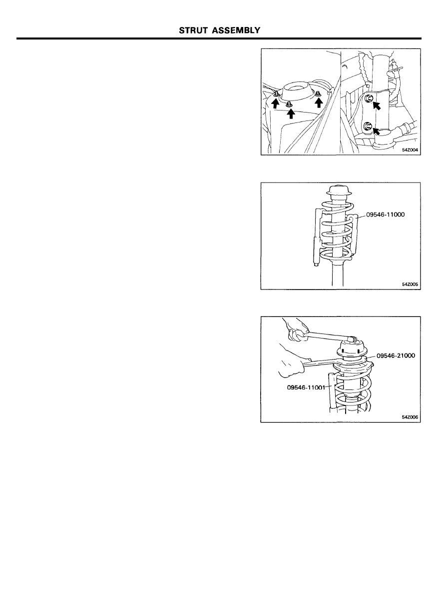
4.
Remove the strut assembly from the knuckle and wheel
house.
DISASSEMBLY
1. Using Special Tool, Spring Compressor (09546-11000/
J38402), compress the coil spring.
2. Holding the upper spring seat with Special Tool, Special
Spanner (09546-21000), loosen the nut at the top end of
the shock absorber and remove the insulator.
3. Remove the spring seat, spring and rubber bumper.
INSPECTION
1. Check the bearing for wear.
2. Check the rubber parts for cracks and wear.
3. Check the coil spring for sagging and weakness.
5 4 - 1 1
STRUT ASSEMBLY
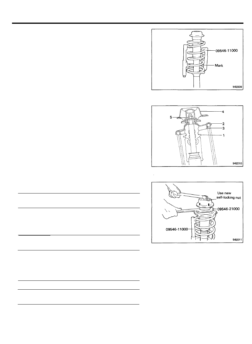
ASSEMBLY
1. Install Special Tool (09546-11000/J38402), on the coil
spring and compress the spring. After the spring is fully
compressed, install it on the strut sub-assembly.
NOTE
Install the coil spring with the identification mark directed
toward the knuckle.
2. Install the rubber bumper, upper rubber seat, upper seat
assy, insulator and washer in the order.
NOTE
Align the D-shaped hole in the spring seat upper assembly
with the indentation on the piston rod.
3. After having correctly seated the upper and lower ends of
the coil spring in the upper and lower spring seat grooves,
loosen Special Tool (09546-11000/J38402).
4. Using Special Tool (09546-21000), hold the upper spring
seat and tighten the self-locking nut to the specified torque.
Tightening of spring seat to piston rod . . . . . . . . . . . . . . . . . .
39-49 Nm (400-500 kg.cm, 29-36 Ib.ft)
5.
Pack grease in the strut upper bearing and install the cap.
CAUTION
Make sure that no grease is on the insulator rubber.
Recommended grease . . . . . . . . . . . . . . . . . . . . . . . . . . . . . . . . . .
Multipurpose grease SAE J310, NLGI No.2
INSTALLATION
1.
When installing the strut, the mating surface must be clean.
2. Tighten the following parts to the specified torque.
Tightening torque
Nm (kg.cm, Ib.ft)
Upper strut installation nut
1 5 - 2 0 ( 1 5 0 - 2 0 0 , 1 1 - 1 4 )
Knuckle to strut assembly
7 4 - 8 8 ( 7 5 0 - 9 0 0 , 5 4 - 6 5 )
3. Install the brake hose and bleed the brake system.
5 4 - 1 2
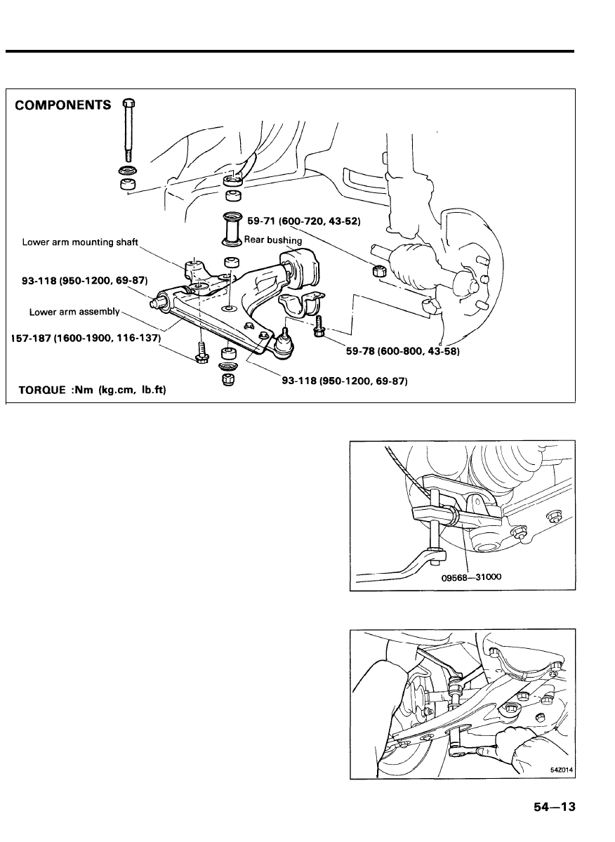
LOWER ARM
LOWER ARM
REMOVAL
1. Using Special Tool (09568-31000), disconnect the lower
arm ball joint from the knuckle.
NOTE
Be sure to tie a cord to the special tool and to a nearby
part.
2. Remove the stabilizer bar mounting bolt and nut, and detach
the stabilizer bar from the lower arm.
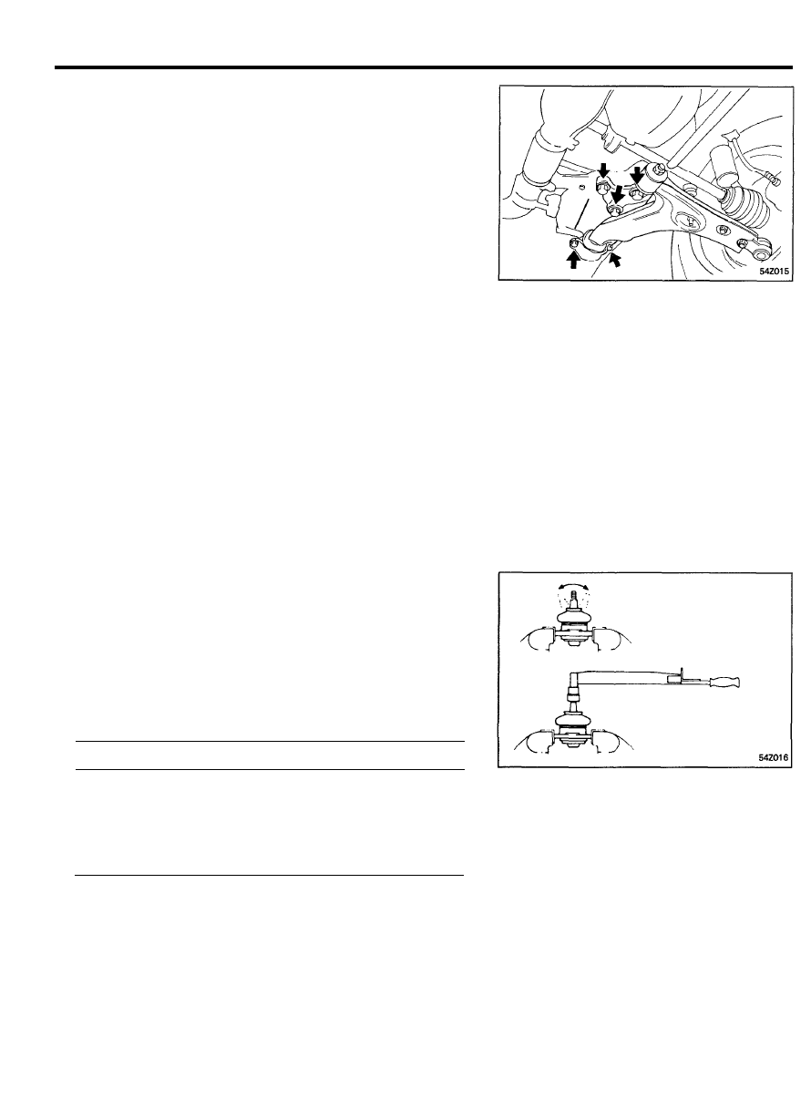
LOWER ARM
3. Detach the lower arm bracket. Remove the lower arm
mounting shaft bolts and separate.
4. Remove the lower arm.
INSPECTION
1. Check for cracked, deteriorated or worn bushings.
2. Check for bent or cracked lower arm.
3. Check for damaged boot,
INSPECTION OF BALL JOINTS
1. Remove the ball joint assembly from the lower arm.
2. Inspect the ball joints for rotation condition.
1)
As shown in the figure, flip the ball joint stud back and
forth 5 times.
2) Using a torque gauge, measure rotation starting torque
at 0.5-2 rpm after 3º rocking and rotating torque at
0.5-2 rpm after 3º rocking 30° rotation.
Rotation condition [Standard value]
Nm (kg.cm, Ib.in.)
Vertical play . . . . . . . . . . . . . . . . . . . . . . . . . . . . . . . . . . . . . . . . . .
0
Rotation starting torque . . . . . . . . . . . . . . . . . . . . . . . . . . . . . . . . .
2 . 9 - 9 . 8 ( 3 0 - 1 0 0 , 2 6 . 0 - 8 6 . 8 )
Rotating torque . . . . . . . . . . . . . . . . . . . . . . . . . . . . . . . . . . . . . . . . .
2 . 9 - 5 . 9 ( 3 0 - 6 0 , 2 6 . 0 - 5 2 . 1 )
5 4 - 1 4
LOWER ARM
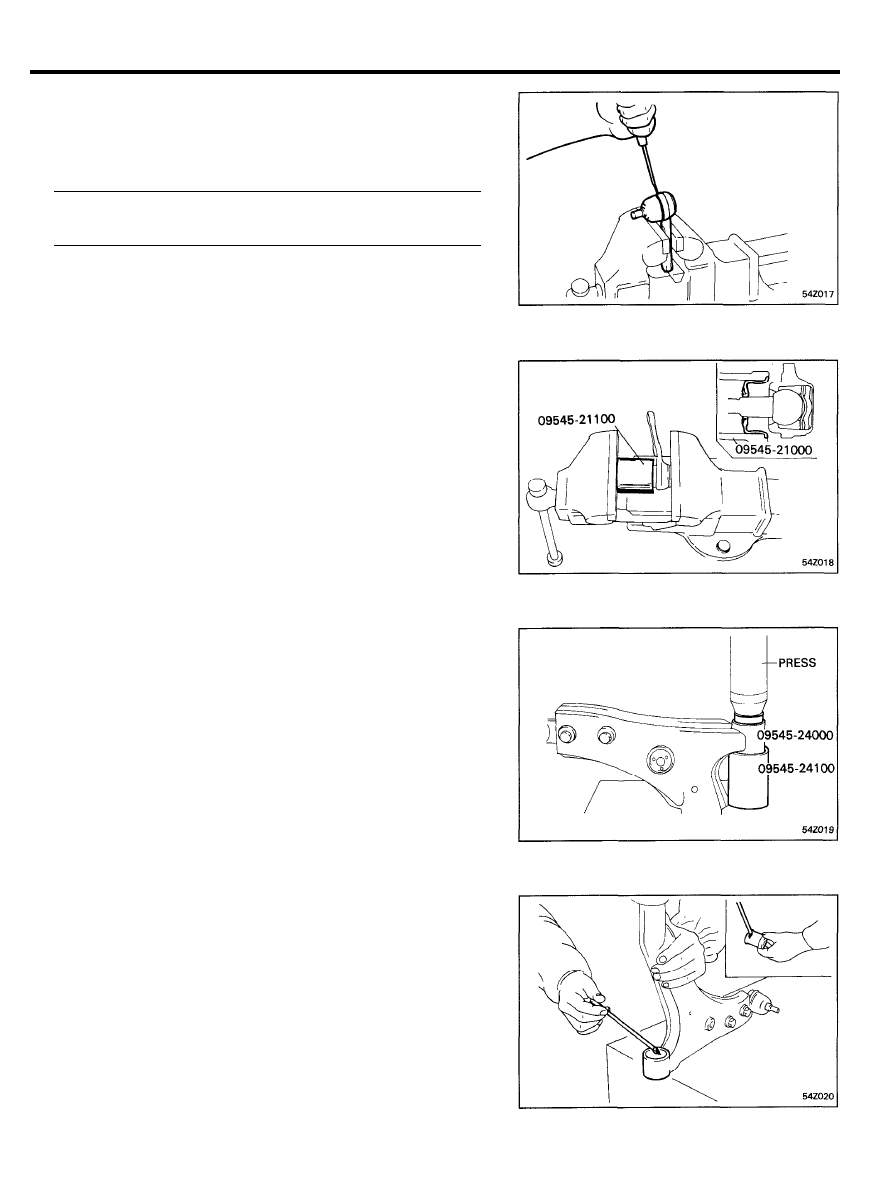
BALL JOINT AND DUST COVER REPLACEMENT
1. Remove the dust cover from the ball joint.
2. Pack the specified grease or equivalent in the new dust
cover.
Recommended grease . . . . . . . . . . . . . . . . . . . . . . . . . . . . . . . . . .
Multipurpose grease SAE J310, NLGI No.2
3. Press fit the dust cover to the ball joint with Special Tool
(09545-21100).
LOWER ARM BUSHING REPLACEMENT
1. Install the Special Tools (09545-21400, 09545-24000,
09545-24100) on the lower arm.
2. Press out the bushing.
3. Apply soap solution to the following portions.
1) Outer surface of the new bushing.
2) Inner surface of the lower arm bushing mount.
3) Inner surface of the Special Tools.
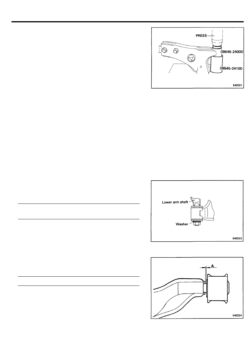
LOWER ARM
4. Install the Special Tools and new bushing onto the lower
arm.
5. Press fit the bushing into the lower arm bushing mount.
6.
Center the bushing by the following procedure, if necessary.
1) Reset the Special Tools and lower arm.
2) Center the bushing.
NOTE
After centering the bushing, wipe off the soap solution.
A S S E M B L Y
1.
Press fit the lower arm mounting shaft and tighten the shaft
mounting nut.
Lower arm mounting shaft mounting nut . . . . . . . . . . . . . . . .
93-118 Nm (950-1200 kg.cm, 69-87 Ib.ft)
2.
Replace the rear bushing, if necessary.
When replacing, the new bushing must be within the specific
distance.
Standard value A . . . . . . . . . 1.5-2.5 mm (0.0594.098 in.)
5 4 - 1 6
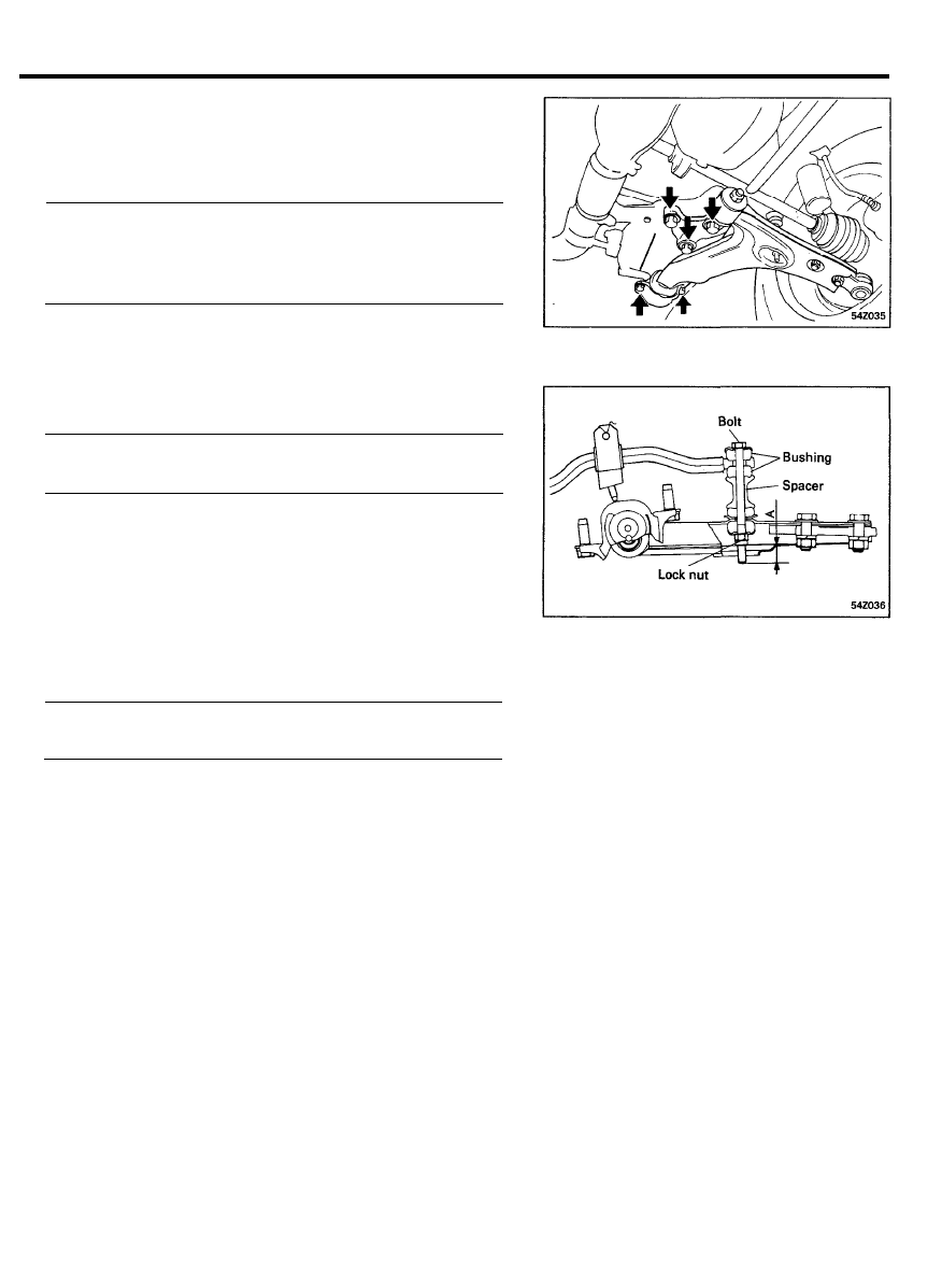
LOWER ARM
INSTALLATION
1. Install the lower arm and lower arm mounting bracket.
2. Install the lower arm mounting shaft into the floor panel
holes and tighten the bolts.
Mounting bracket bolt . . . . . . . . . . . . . . . . . . . . . . . . . . . . . . . . . .
59-78 Nm (600-800 kg.cm, 43-58 Ibft)
Lower arm mounting shaft bolt . . . . . . . . . . . . . . . . . . . . . . . . .
157-187 Nm (1600-1900 kg.cm, 116-137 Ib.ft)
3.
Arrange the stabilizer bar mounting spacer, bushing and cup.
Tighten the lock nut.
Dimension “A” [Standard value] . . . . . . . . . . . . . . . . . . . . . . . . .
2 0 - 2 2 m m ( 0 . 7 8 7 4 . 8 6 6 i n . )
4. Install the ball joint to the knuckle.
Ball joint to knuckle . . . . . . . . . . . . . . . . . . . . . . . . . . . . . . . . . . . . .
59-71 Nm (600-720 kg.cm, 43-52 Ib.ft)
5 4 - 1 7
STABILIZER BAR
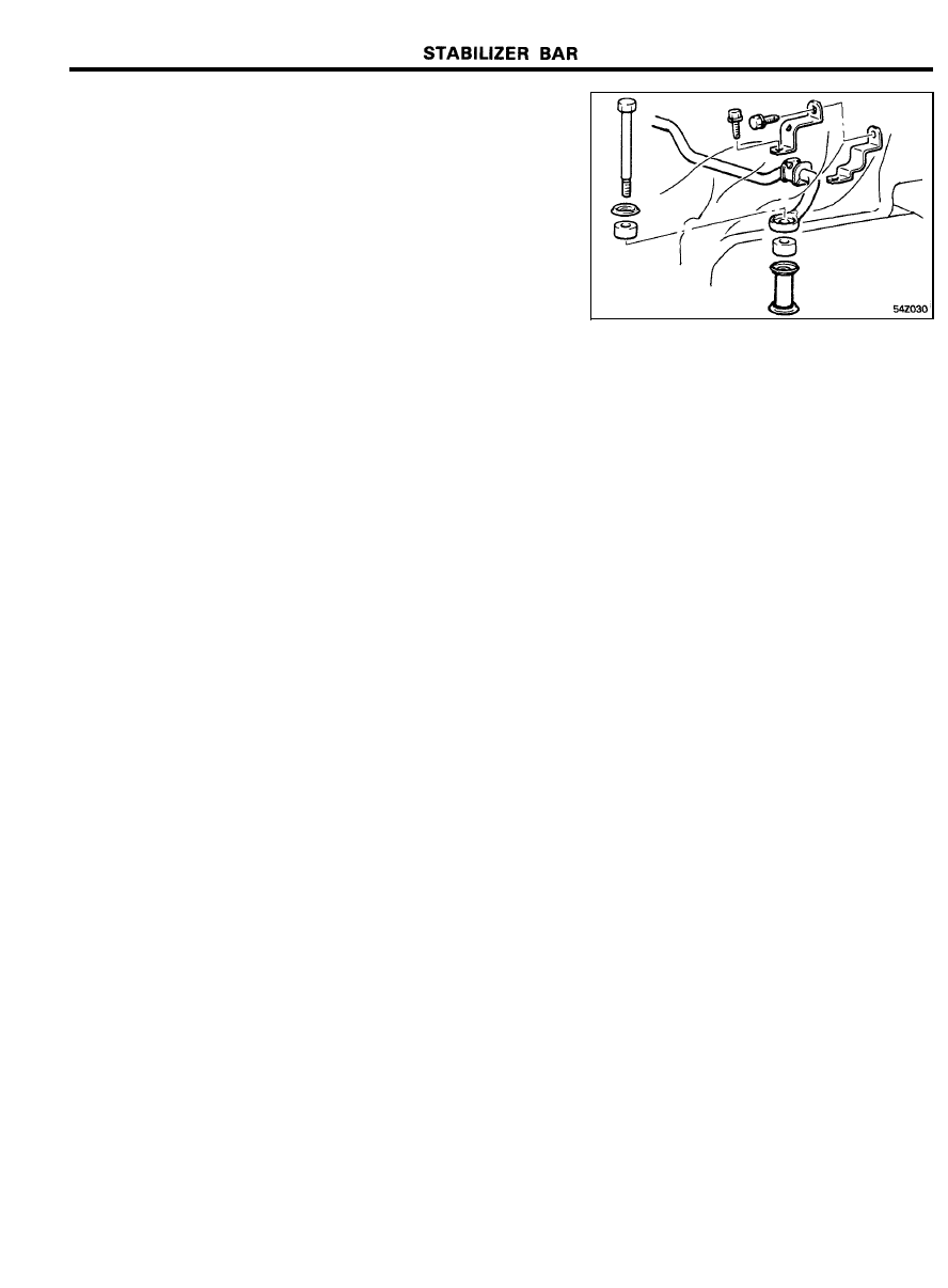
STABILIZER BAR
REMOVAL
1.
Disconnect the tie rod end ball joint from the knuckle using
Special Tool (09568-31000).
NOTE
Be sure to tie a cord to the Special Tool and to a nearby
part.
2. Remove the rear roll stopper mounting bolt and rear roll
bracket assembly mounting bolt.
3. Pull the rear roll bracket assembly forward.
NOTE
Do not disconnect the center member assembly.
5 4 - 1 8
STABILIZER BAR
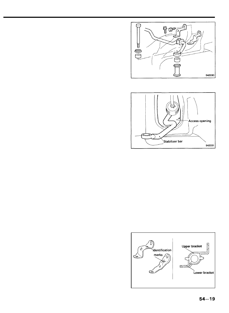
4. Loosen the stabilizer link bolt and nut, then separate the
stabilizer bar from the lower arm.
5.
Loosen the stabilizer bar mounting bolts through the steering
gear box access opening’ provided on the vehicle body.
6. Remove the stabilizer bar through the access opening.
7. Detach the upper and lower brackets; then remove the
bushing.
INSPECTION
1. Check the stabilizer bar for deterioration and damage.
2. Check all bolts for condition and straightness.
INSTALLATION
1. Install the bushing onto the stabilizer bar.
2.
Align the upper and lower brackets with the bushing. Make
sure the projections are securely in the space between the
brackets.
NOTE
When installing, distinguish the brackets by noting their
identification mark.
Identification mark : R for R.H. side
L for L.H. side
3. Using the access opening, temporarily tighten the bushing
brackets, then position the opposite side bushing.
4. Securely tighten the stabilizer bar mounting bolts.
5. Fit the stabilizer link and tighten. (Refer to page 54-17).
6. Reinstall the rear roll bracket assembly.
7. Connect the tie rod end ball joint to the knuckle.
5 4 - 2 0
CENTER MEMBER
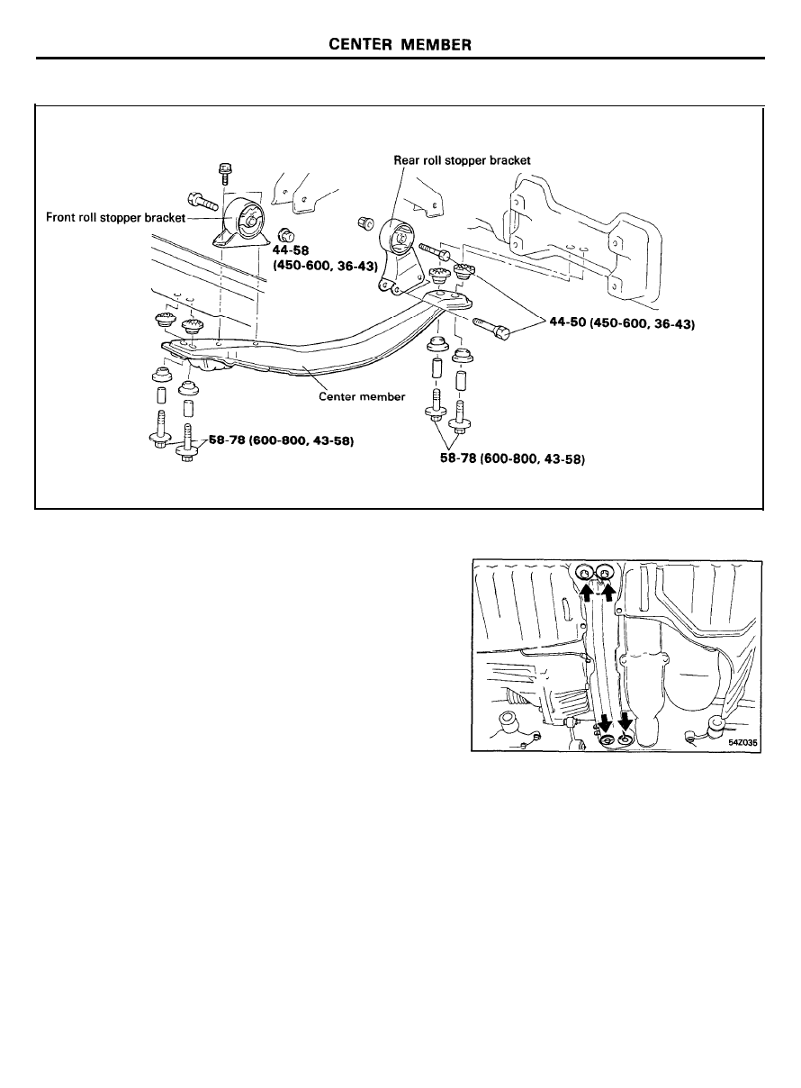
COMPONENTS
TORQUE : Nm (kg.cm, Ib.ft)
REMOVAL
1. Raise the vehicle and position the jack stands.
2. Detach the front and rear roll stopper brackets from the
engine mounting bracket.
3. Remove the center member assembly.
INSPECTION
1.
Check each insulator and bushing for cracks or deterioration.
2. Check each bracket for distorsion or damage.
5 4 - 2 1
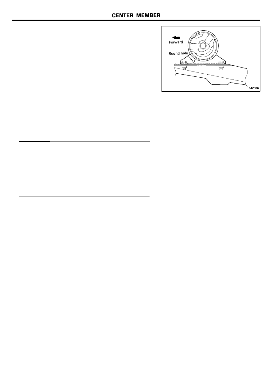
INSTALLATION
1. Install the front roll stopper bracket so that its round hole
faces forward.
2.
Fit the rear roll stopper bracket to the center member, and
install the center member assembly.
3. Temporarily tighten the front roll stopper bracket bolt. After
the total weight of the engine has been placed on the vehicle
body, securely tighten the nut.
Center member mounting bolt . . . . . . . . . . . . . . . . . . . . . . . . . .
59-78 Nm (600-800 kg.cm, 43-58 Ib.ft)
Front roll stopper bracket to center member bolt . . . . . . . .
29-39 Nm (300-400 kg.cm, 25-29 Ib.ft)
Rear roll stopper bracket to center member bolt . . . . . . . . .
44-59 Nm (450-600 kg.cm, 33-43 Ib.ft)
Insulator to engine. mounting bracket bolts . . . . . . . . . . . . . .
44-59 Nm (450-600 kg.cm, 33-43 Ib.ft)
5 4 - 2 2
WHEEL AND TIRE
WHEEL AND TIRE
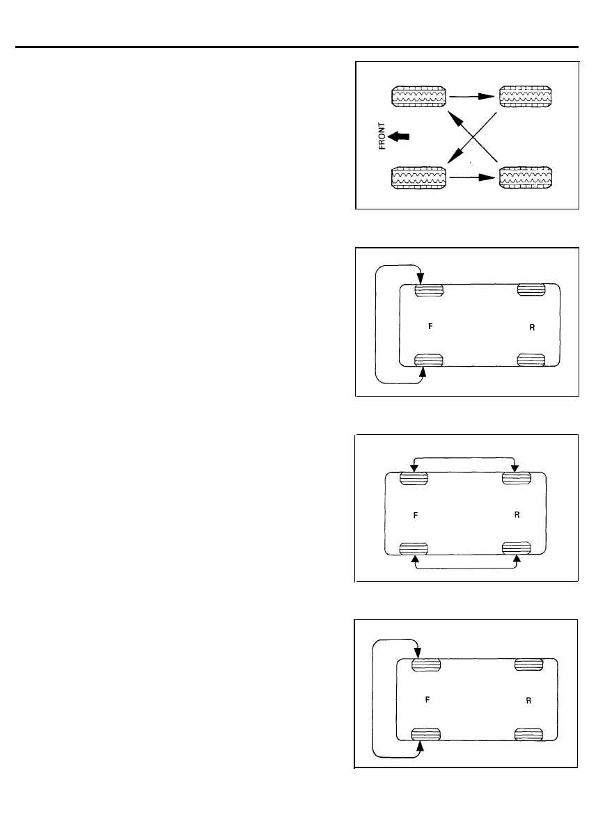
WHEEL ROTATION
1. Rotate the tires in the patterns illustrated.
CAUTION
The temporary spare tire should not used in the wheel
rotation.
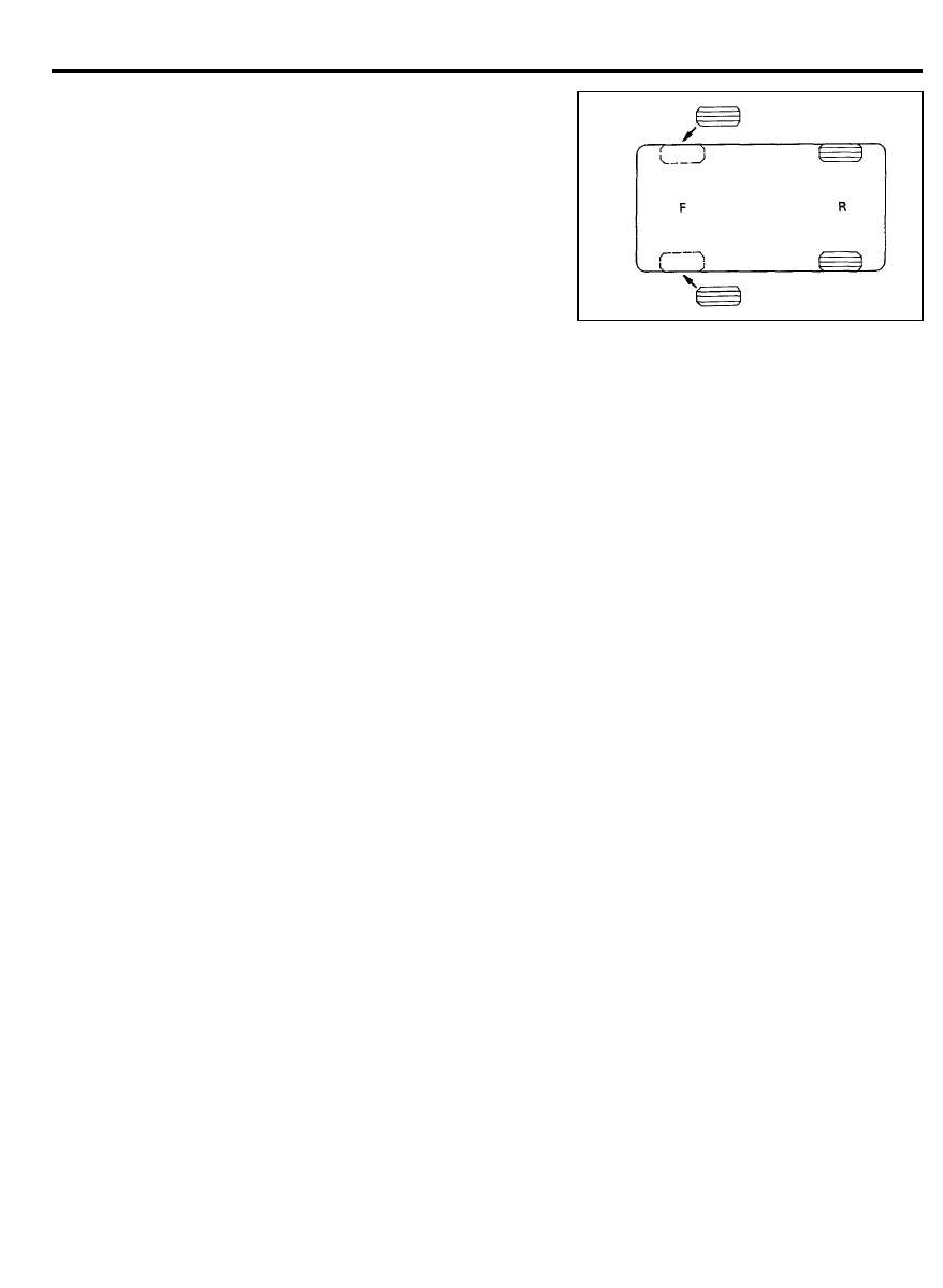
Checking for pull and wander
1. If the steering pulls to one side, use the following wheel
rotation procedure.
1) Switch the front right and front left tires, and perform
the road test in order to confirm vehicle stability.
2)
If the steering pulls to opposite side, switch the front and
rear tires, and again perform the road test.
3)
If the steering continues to pull to one side, switch the
front right and left tires again, and again perform the
road test.
5 4 - 2 3
WHEEL AND TIRE
4) If the steering continues to pull to the opposite side,
replace the front wheels with new ones.
INSTRUCTIONS FOR ALUMINUM TYPE WHEELS
1. Aluminum is vulnerable to alkalies. If the vehicle has been
exposed to automobile washing detergent, or salt from sea
water, or road chemicals, rinse the vehicle as soon as
possible. Then apply wax to the wheels to prevent corrosion.
2. When steam cleaning the vehicle, do not direct the steam
onto the aluminum wheels.
When tightening nuts for aluminum wheels, observe the
following:
1) Clean the hub surface.
2) After finger-tightening the wheel nuts, tighten to
specifications.
3)
Do not use an impact wrench or push the wrench by foot
to tighten the wheel nuts.
4) Do not apply oil to the threaded portions.
TIRE CHAINS AND SNOW TIRES
1. Use tire chains only on the front wheels. Do not use tire
chains on rear wheels.
2. When using snow tires, use them on all four wheels for
maneuverability and safety.
CAUTION
Do
not use tire chains on the P175/70 R13 tires.
Interference between the tire chains and the front wheel
house can occur if chains are used on the P175/70 R13
tires.
5 4 - 2 4
Wyszukiwarka
Podobne podstrony:
26 Front Suspension
FRONT SUSPENSION
Jag front suspension xk 120,xk 140,xk 150;mk VII,mk VIII,mk IX
M32c Front Suspension
26 Front Suspension
26 Front Suspension
26 Front Suspension
Front suspension strut
g3 front suspension
13 Front Suspension
26 Front Suspension
ARTICLE SUSPENSION STRUT FRONT REPLACE INSTALL
ARTICLE SUSPENSION STRUT FRONT DISASSEMBLE REASSEMBLE
11 Front Wheel Suspension Steering
ARTICLE SUSPENSION LOWER CONTROL ARM FRONT SERVICE
więcej podobnych podstron