223
In This Chapter
13
Calculating Shafts
In this AutoCAD
®
Mechanical 6 tutorial, you perform a
calculation on an existing shaft and apply various loads to
a supported shaft. Then you insert the results into a
drawing.
■
Creating the shaft contour
■
Specifying the material
■
Placing the supports
■
Specifying the loads
■
Calculating and inserting the
results
■
Calculating the strength

224
|
Chapter 13
Calculating Shafts
Key Terms
Term
Definition
deflection line
Deflection line calculations are based on the predefined force direction (F) or the
radial direction (s).
deflection moment
Deflection moment calculations are based on the predefined force direction (F) or
the radial direction (s).
fatigue factor
A summary term for all safety factors, which are necessary to determine the safety
against endurance or fatigue fractures.
fixed support
A support that is fixed to a part and cannot be moved.
gear
Any several arrangements, especially of toothed wheels in a machine which allows
power to be passed from one part to another so as to control the power speed or
the direction of movement.
load
The forces and moments that act on a part.
movable support
A support that is not fixed.
notch
A change of cross section, for example undercuts, grooves, holes or shoulders.
Notches lead to a higher stress in the part. The flux of the stress is interrupted or
redirected.
point force
A force that is concentrated on a point.
strength
A summary term for all forces and moments, thus loads and stress, which act on a
part.
stress
Force or pressure on a part. Stress is the force per area.
yield factor
A summary term for all safety factors, which are necessary to determine the safety
against overload fracture under maximum load.
Calculating Shafts
|
225
Calculating Shafts
With AutoCAD Mechanical, you can perform a shaft calculation using a con-
tour created with the Shaft Generator or any other symmetric shaft contour.
The function provides a static calculation, which is important for the design
of the shaft and the bearing load.
NOTE
The ISO standard parts have to be installed for this tutorial exercise.
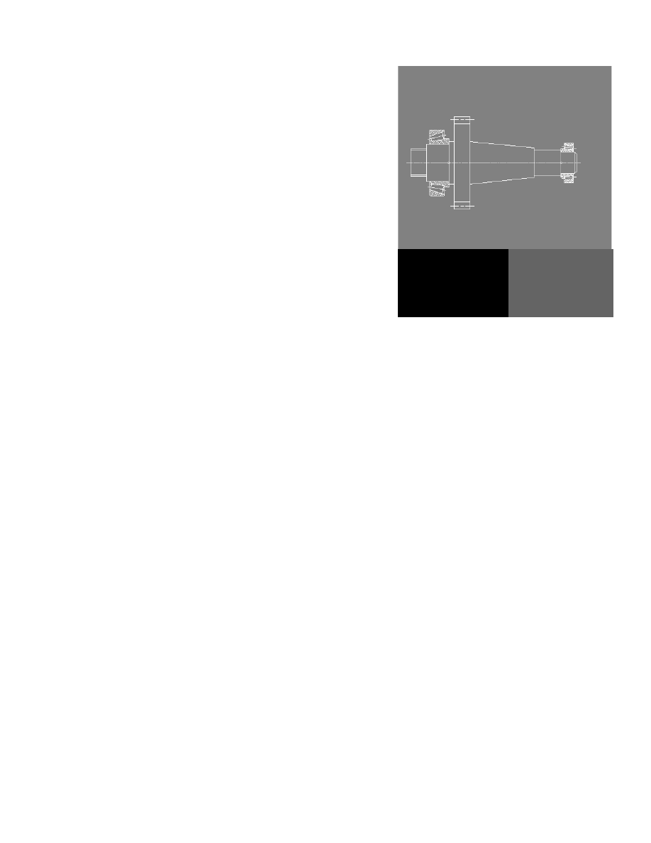
In this tutorial, you calculate a gear box shaft. The general way to calculate
an existing shaft is to define the contour and insert forces and supports. The
routine calculates all necessary values and draws the respective graphs for
moment and deflection.
First, you load the initial drawing.
To open a file
1
Open the file tut_ex11 in the acadm\tutorial folder.
Menu
File ➤ Open
Command
OPEN
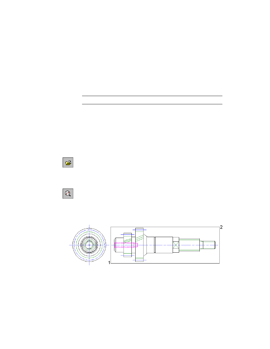
The drawing contains a shaft in front and side view.
2
Zoom in to the shaft.
Menu
View ➤ Zoom ➤ Window
Command
ZOOM
3
Respond to the prompts as follows:
Specify first corner:
Specify the first corner point (1)
Specify opposite corner:
Specify the second corner point (2)
Save your file under a different name or to a different directory to preserve
the original tutorial file.
226
|
Chapter 13
Calculating Shafts
Creating Shaft Contours
Before you can perform any calculations on a shaft, you have to create the
shaft contour.
To create a shaft contour
1
Start the Shaft Calculator.
Menu
Content ➤ Calculations ➤ Shaft Calculation
Command
AMSHAFTCALC
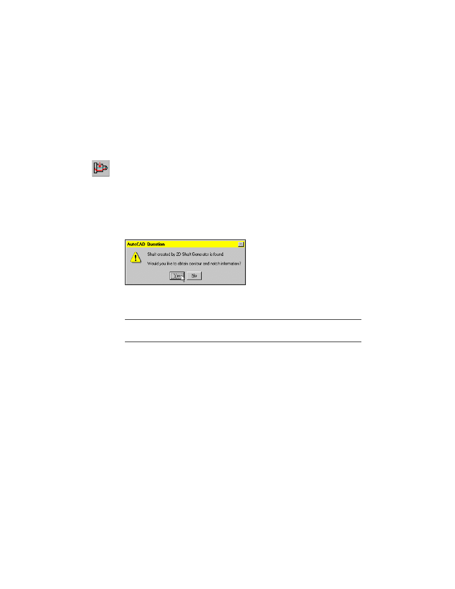
2
Respond to the prompts as follows:
Select contour or [Create contour/Strength] <Create>:
Enter C
Select objects:
Select the complete shaft
Select objects:
Press
ENTER
3
In the AutoCAD Question dialog box, choose Yes.
4
Respond to the prompts as follows:
Specify contour position:
Press
ENTER
NOTE
The calculation routine recognizes hollow shafts and uses the contour
for the calculation.
Calculating Shafts
|
227
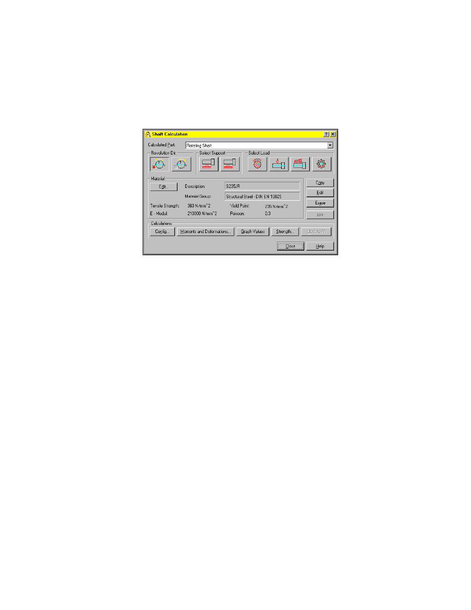
After you have created the shaft contour, the Shaft Calculation dialog box is
displayed so that you can select the boundary conditions, the material, and
the representation of the calculation results.
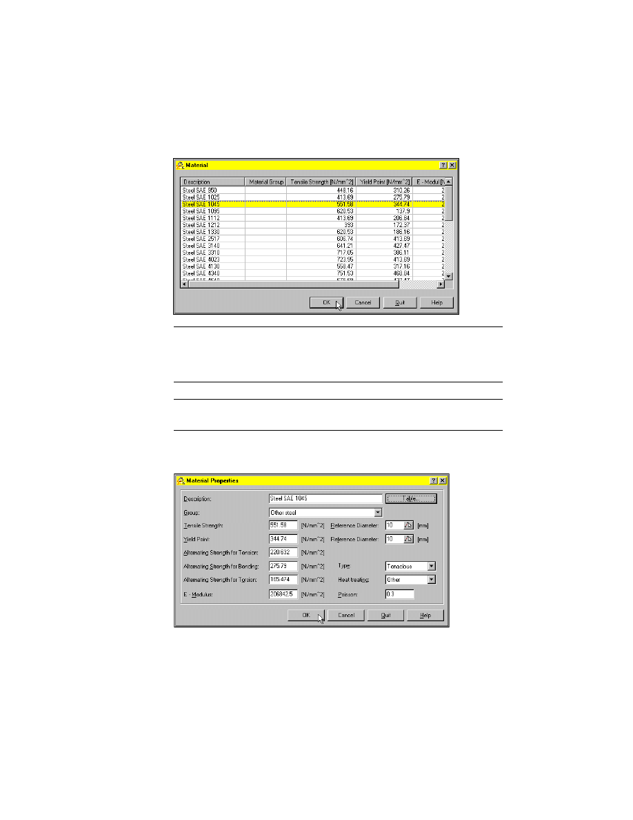
Specifying Material
You specify the material by selecting it from a table containing the most com-
monly used materials. You are also able to enter the characteristics for other
materials using the option Edit.
To specify a material
1
From the Material section, choose Edit.
The Material Properties dialog box is displayed.
2
In the Material Properties dialog box, choose Table, and select the ANSI
standard.
228
|
Chapter 13
Calculating Shafts
3
In the Material dialog box, select the material Steel SAE 1045 from the table.
Choose OK.
NOTE
If the ANSI standard is not installed on your system, you can select a
different standard, but the results may differ from the results in this tutorial (if
you select DIN for example, you can select a similar material like, E335, to
achieve similar results).
NOTE
Some material properties are not complete. In this case, you have to
complete them to obtain calculation results.
4
In the Material Properties dialog box, complete the ANSI material properties
if necessary:
5
Choose OK.
Calculating Shafts
|
229
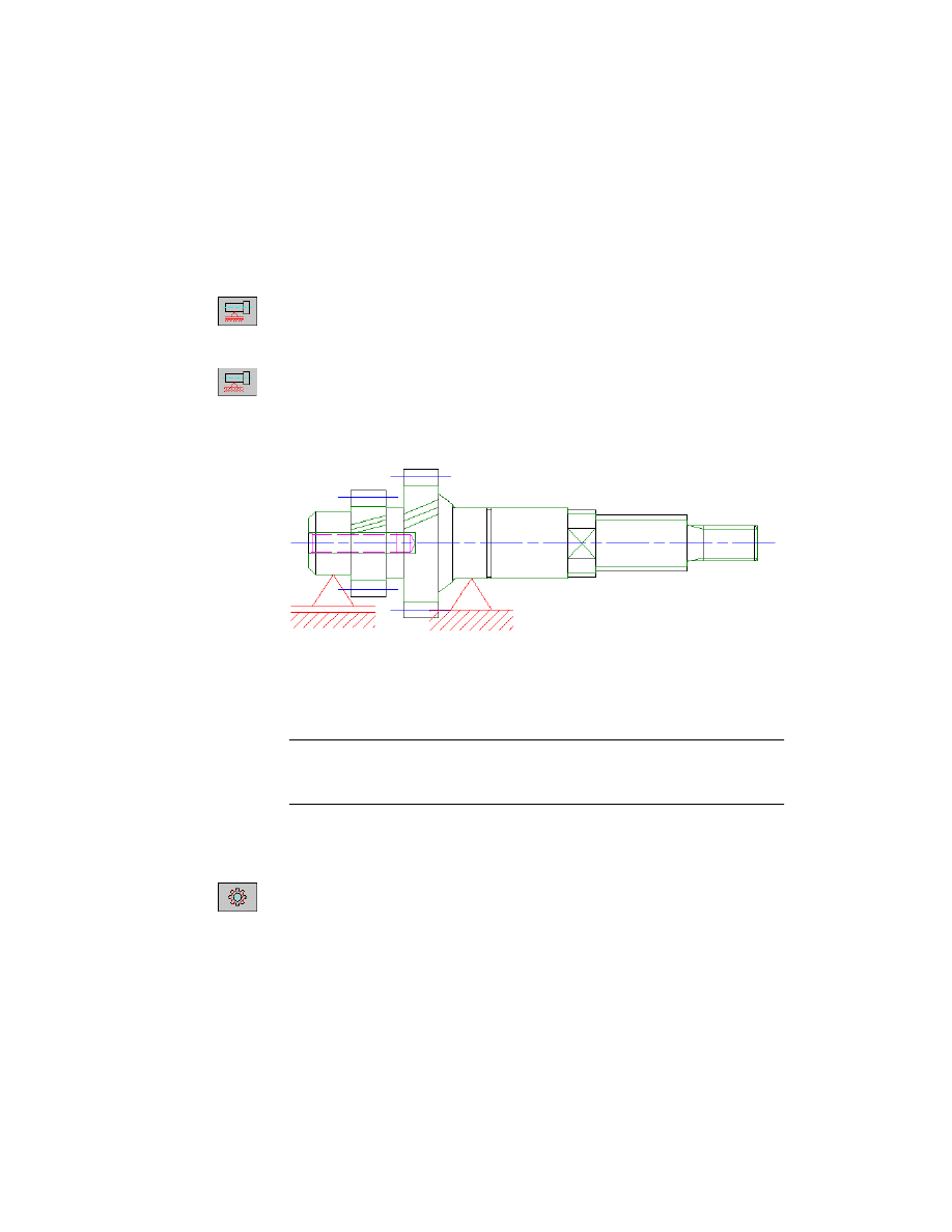
Placing Shaft Supports
Now, you have to specify the shaft supports.
To place a support
1
In the Shaft Calculation dialog box, select the Movable Support icon, and
respond to the prompt as follows:
Specify insertion point:
Select the midpoint of the leftmost shaft section
2
Now, select the Fixed Support icon, and respond to the prompt as follows:
Specify insertion point:
Select the midpoint of the third cylindrical shaft section
Now, you have specified the shaft supports and your result should look like
this:
Specifying Loads on Shafts
Now, you have to specify the effective loads. AutoCAD Mechanical uses
geometry from the drawing for load calculations.
NOTE
The loads depend on the setting Calculated Part. There are three pos-
sibilities: Rotating Shaft, Rotating Axle and Not rotating Axle. A shaft is able to
transfer torque and rotating axles result in different stress values than static axles.
To specify a load
1
From the Calculated Part drop-down list, choose Rotating Shaft.
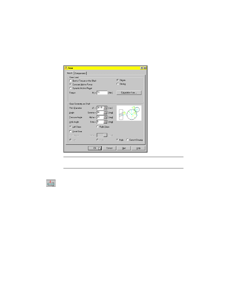
2
Choose the Gear icon and respond to the prompt as follows:
Specify insertion point:
Select the midpoint of the second gear
230
|
Chapter 13
Calculating Shafts
3
In the Gear dialog box, activate the tab Inputs, and specify:
Gear Load:
Driven
Torque:
15
NOTE
The Components tab displays the force components. Changes in one
tab are automatically reflected in the other tab.
4
Choose OK.
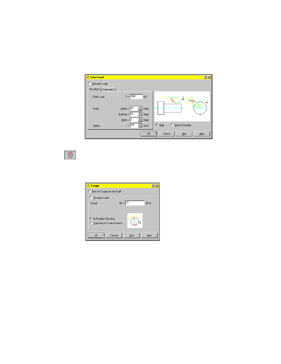
5
Choose the Point Load icon and respond to the prompts as follows:
Specify insertion point:
Select the midpoint of the profile section
Specify rotation angle:
Press
ENTER
Calculating Shafts
|
231
6
In the Point Load dialog box, activate the Resultant tab, and specify:
Point Load:
2500
7
Choose OK.
8
Choose the Torque icon and respond to the prompt as follows:
Specify insertion point:
Select the midpoint of the profile section
9
In the Torque dialog box, specify:
Torque:
15
Choose OK.
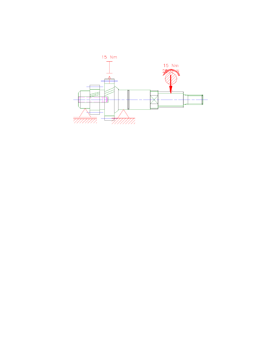
Now, you have specified the loads and your result should look like this:
232
|
Chapter 13
Calculating Shafts
You have specified all boundary conditions necessary for a shaft calculation.
Calculating and Inserting Results
Now, you perform a calculation of the moments and deformations, and
insert the results in your drawing.
To perform a shaft calculation
1
Choose the Moments and Deformations button.
Calculating Shafts
|
233
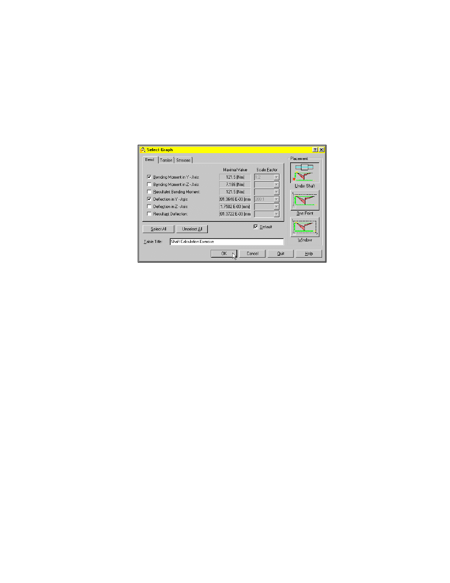
2
In the Select Graph dialog box, specify:
Bend:
Bending Moment in Y - Axis, Deflection in Y - Axis
Torsion:
Torsion Moment in X - Direction
Stresses:
Result Bending Stress
Table Title:
Shaft Calculation Exercise
3
Choose OK, and respond to the prompts as follows:
Specify insertion point:
Select an appropriate point to the right of the shaft
The result block as well as the deflection and torsion moment graphs are
inserted.
4
Choose Close to exit the Shaft Calculation dialog box.
234
|
Chapter 13
Calculating Shafts
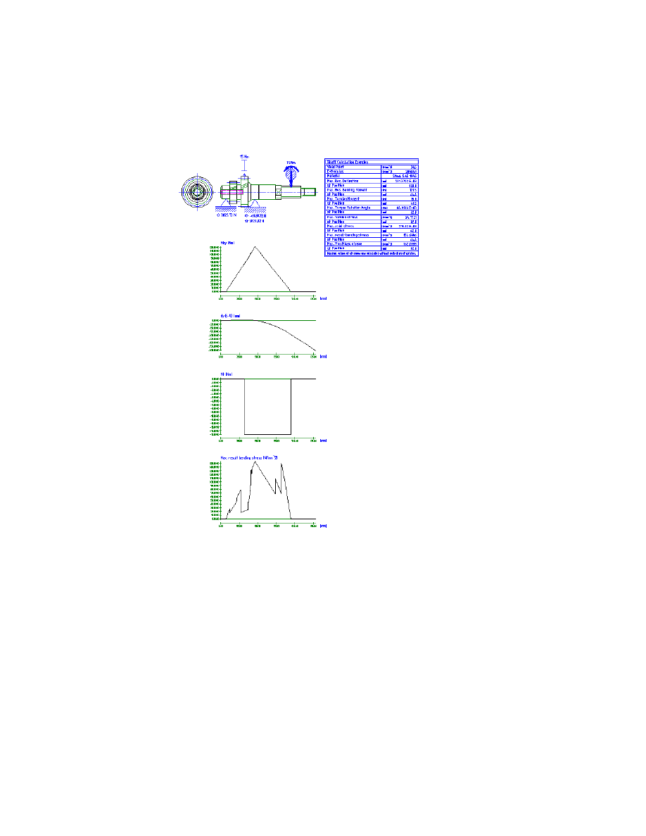
Now, your drawing should look like this:
The result block provides the most important information about your
calculated shaft such as the maximum stress deflection and moment values.

Calculating Shafts
|
235
Save your file.
Calculating Strengths of Shafts
Now, check the strength at a critical place of the shaft, for example a notch.
To calculate the strength at a notch
1
Restart the Shaft Calculation
Menu
Content ➤ Calculations ➤ Shaft Calculation
Command
AMSHAFTCALC
2
Respond to the prompt as follows:
Select contour or [Create contour/Strength] <Create>:
Select the shaft contour
The Shaft Calculation dialog box opens again and you are able to continue
with calculations on the previously specified shaft.
236
|
Chapter 13
Calculating Shafts
3
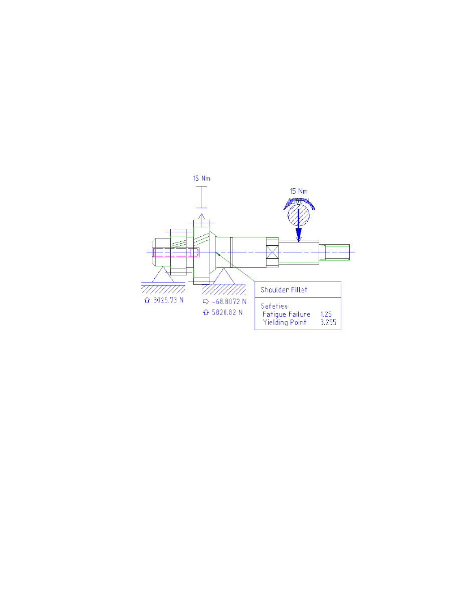
In the Shaft Calculation dialog box, choose the Strength button, and respond
to the prompt as follows:
Specify calculation position on shaft or [Graph]:
Specify the notch at the end of the conical section (1) (make sure you don’t select
the endpoint of the cylindrical shaft section)
NOTE
This notch has been selected because the calculation established that
the highest bending stress is close to this place.
The Strength Calculation dialog box opens.
Calculating Shafts
|
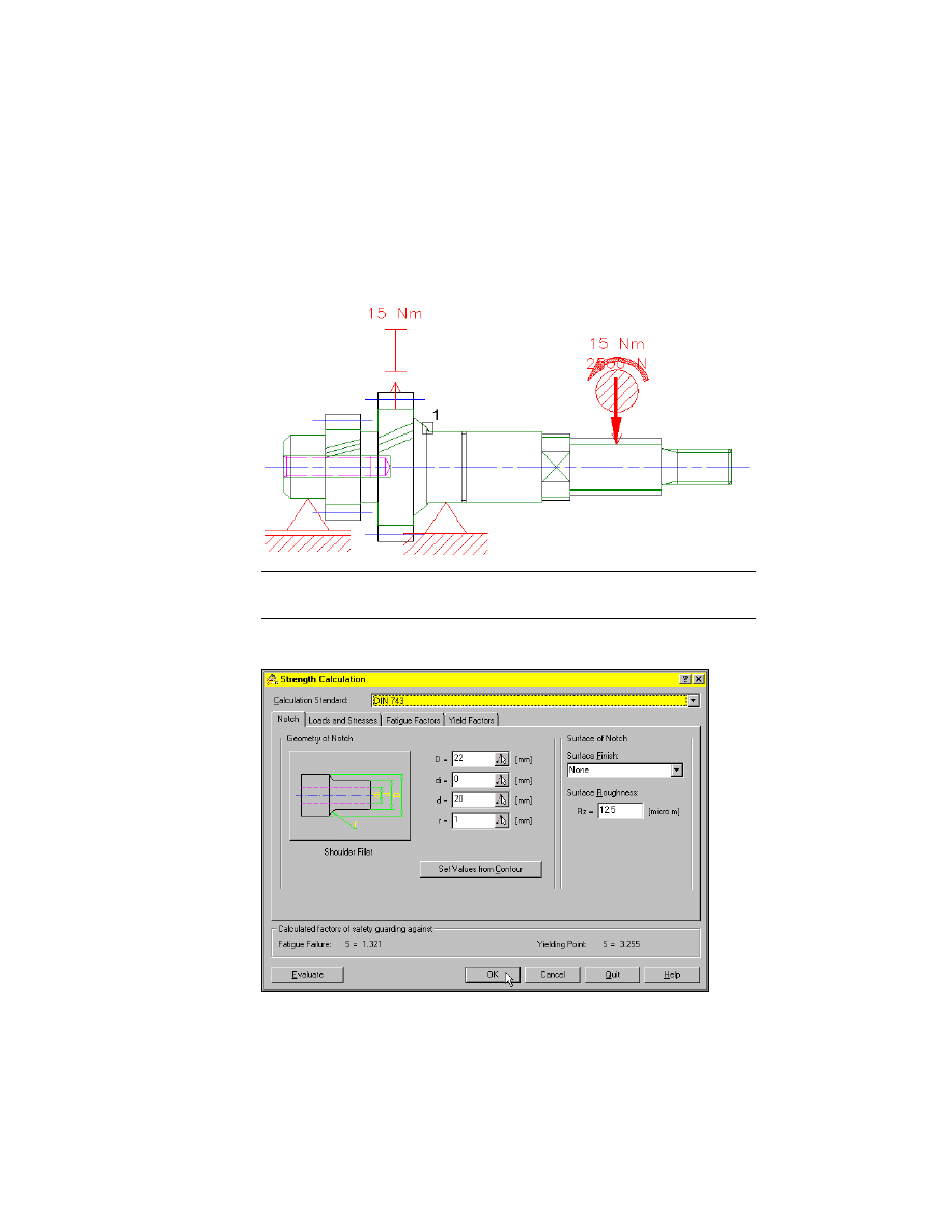
237
The Strength Calculation dialog box enables you to specify the properties of
the notch more detailed and displays all important strength values and factors.
4
Choose OK and respond to the prompt as follows:
Specify next point <Symbol>:
Specify a point below the shaft
Specify next point <Symbol>:
Press
ENTER
The result block is inserted in the drawing.
As you can see, the safety factors are higher than 1.2. The shaft doesn’t need
to be redesigned at this notch.
5
Choose Close to leave the Shaft Calculation dialog box.
This is the end of this tutorial chapter.
Save your file.

238
Document Outline
Wyszukiwarka
Podobne podstrony:
CH13
Ch12 Shafts with Standard Parts
Ch13 Q4
cisco2 ch13 concept DEPLAEMNY56CXKYBER7D5JJA4Y4E4WS45RAVJSI
Ch13 Drawing Views
Ch13 Q3
CH13 2
Ch13 Q1
Ch13
Ch23 Shafts
ch13
Ch13 Q2
Genomes3e ppt ch13
ch13
Ch13 PolutionAndItsControll
Ch13 rolling
Ch13 Pg441 484
więcej podobnych podstron