
23
C
C
h
h
a
a
p
p
t
t
e
e
r
r
3
3
:
:
S
S
e
e
t
t
u
u
p
p
About the Setup Utility
This chapter explains how to use and modify the BIOS setup utility that is
stored on the mainboard. The setup utility stores information about the
mainboard components, and the configuration of other devices that are
connected to it. The system uses this information to test and initialize
components when it is started up, and to make sure everything runs
properly when the system is operating.
The setup utility is installed with a set of default values. The default
values are designed to ensure that the system will operate adequately.
You will probably have to make changes to the setup utility whenever
you add new components to your system such as new disk drives. You
may be able to generate increased performance by changing some of
the timing values in the setup, but this can be limited by the kind of
hardware you are using, for example the rating of your memory chips. In
certain circumstances, the system may generate an error message
which asks you to make changes to the setup utility. This happens when
the system finds an error during the POST (power on self test) that it
carries out at start up.
Starting the Setup Utility
You can only start the setup utility shortly after the computer has been
turned on. A prompt appears on the computer display which says “ Press
DEL to run Setup” . When you see this prompt, press the Delete key, and
the system will start the setup utility and display the main menu of the
utility.
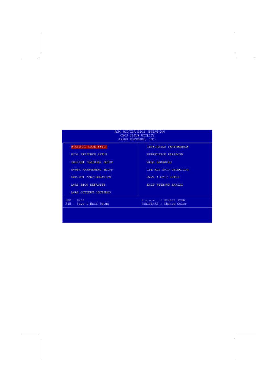
Using the Setup Utility
When you press the Delete key to start setup, the main menu of the
utility appears.
The main menu of the setup utility shows a list of the options that are
available in the utility. A highlight shows which option is currently
selected. You can use the cursor arrow keys to move the highlight to
other options. When an option is highlighted, you can execute the option
by pressing the Enter key.
24
Some options lead to dialog boxes which ask you verify that that you
wish to execute that option. You usually answer these dialogs by typing
Y for yes and N for no.
Some options lead to dialog boxes which ask for more information.
Setting the User Password or Supervisor Password have this kind of
dialog box.
Some options lead to tables of items. These items usually have a value
on the right side. The value of the first item is highlighted, and you can
use the cursor arrow keys to select any of the other values in the table of
items. When an item is highlighted, you can change the value by
pressing the PageUp or PageDown keys, or the Plus or Minus keys.
The PageUp and Plus keys cycle forward through the available values,
the PageDown and Minus keys cycle backwards through the values.
When you are in the main menu, you can exit the utility by pressing the
Escape key. You can save the current selections and exit the utility by
pressing the F10 key. You can change the color scheme of the utility by
pressing the F2 key while holding down the Shift key.
When you are in one of the options that displays a dialog box, you can
return to the main menu by pressing the Escape key.
25
When you are in one of the options that displays a table of items, you
can return to the main menu by pressing the Escape key. For some
items, you can display a help message by pressing the F1 key. You can
change the color scheme of the utility by pressing the F2 key while
holding down the Shift key. You can press F5 to discard any changes
you have made and return all items to the value that they held when the
setup utility was started. You can press F6 to load the displayed items
with a standard list of default values. You can press F7 to load the
displayed items with a high-performance list of default values.
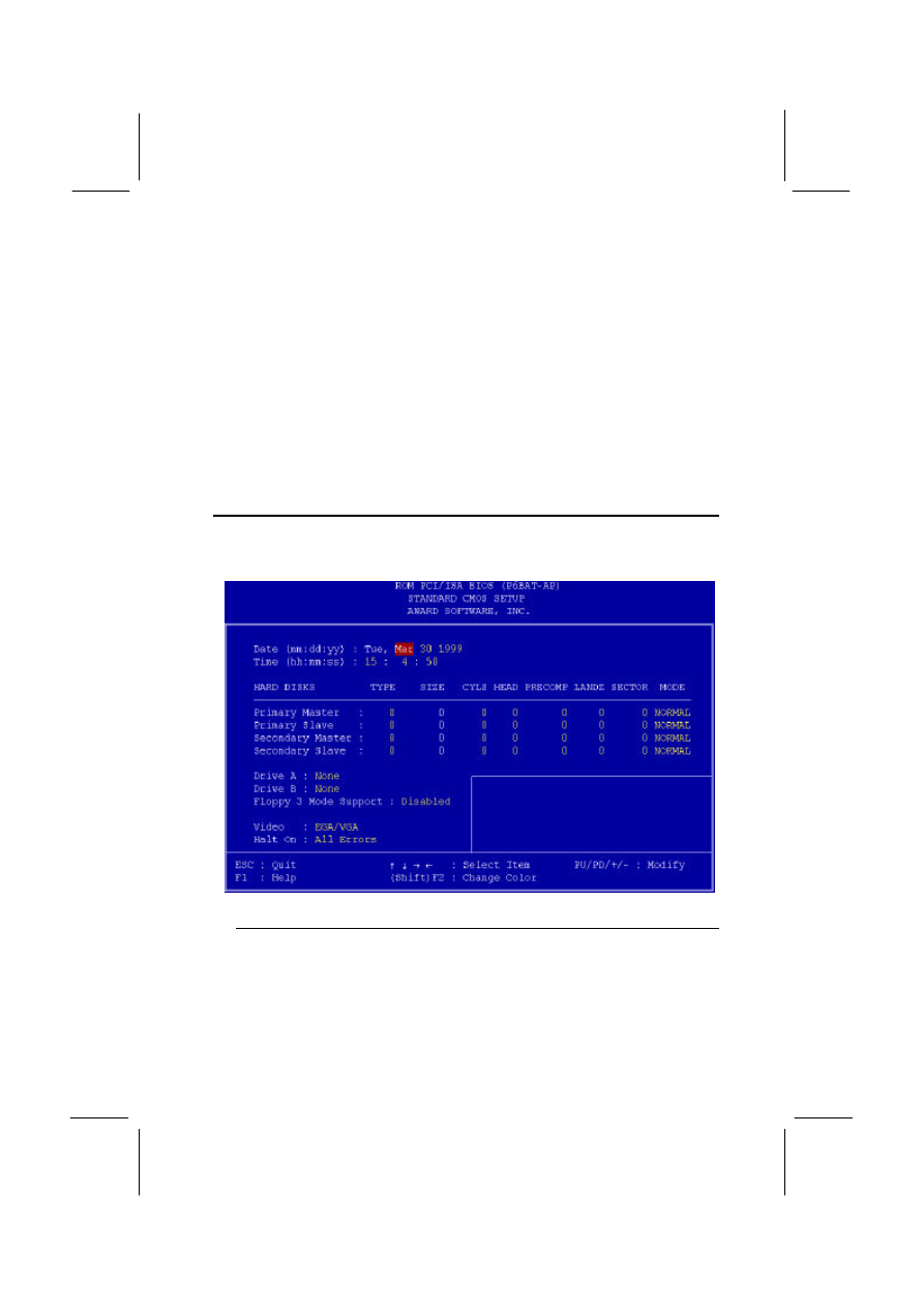
Standard CMOS Setup Option
This option displays a table of items which defines basic information
about your system.
Date and Time
The Date and Time items show the current date and time held by your computer.
If you are running a Windows operating system, these items will automatically be
updated whenever you make changes to the Windows Date and Time Properties
utility.

26
Hard Disks
Defaults: Auto
These items show the characteristics of any hard disk drives on the four
available IDE channels. (Note that SCSI hard disk drives do not appear here.)
You can automatically install most modern hard disks using the IDE HDD Auto
Detect Option from the main menu. However, if you find that a drive cannot be
automatically detected, you can use these items to select USER, and then
manually enter the characteristics of the drive. The documentation provided with
your drive provides the data you need to fill in the values for CYLS (cylinders),
HEAD (read/write heads), and so on.
The documentation provided with the drive may not tell you what value to use
under the MODE heading. If the drive is smaller than 528 MB, set MODE to
Normal. If the drive is larger than 528 MB and it supports Logical Block
Addressing, set MODE to LBA. Very few high-capacity drives do not support
Logical Block Addressing. If you have such a drive, you might be able to
configure it by setting the MODE to Large. If you’ re not sure which MODE
setting is required by your drive, set MODE to Auto and let the setup utility try to
determine the mode automatically.
Drive A and Drive B
Default: None , None
These items define the characteristics of any diskette drive attached to the
system. You can connect one or two diskette drives.
Floppy 3 Mode Support
Default: Disabled
Floppy 3 mode refers to a 3.5” diskette with a capacity of 1.2 MB. Floppy 3 mode
is sometimes used in Japan.
Video
Default: EGA/VGA
This item defines the video mode of the system. This mainboard has a built-in
VGA graphics system so you must leave this item at the default value.
Halt On
Default: All Errors
This item defines the operation of the system POST (Power On Self Test) routine.
You can use this item to select which kind of errors in the POST are sufficient to
halt the system.
Base, Extended and Other Memory.
These items show how much memory is available on the system. They are
automatically detected by the system so you cannot manually make changes to
these items.
BIOS Feature Setup Option
This option displays a table of items which defines more advanced
information about your system. You can make modifications to most of
these items without introducing fatal errors to your system.
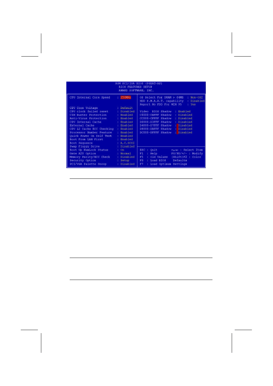
27
CPU Internal Core Speed
Default: 350MHz
This item should be installed with the rated internal core speed of the Pentium-II
class processor that is installed in your system. The setup utility will then
automatically configure the system with the correct host bus speed, and bus
frequency multiplier.
If you set this item to Manual, two new items will appear: CPU Host BUS
Frequency and CPU Core:Bus Freq. Multiple. You can use these two items to
manually configure the mainboard for the speed of the processor. The values
available in these two items will vary, according to the kind of Pentium-II
processor that is installed.
Note: Using the three items above, you can configure the
mainboard so that it runs a processor faster than the rated clock
speed. We strongly recommend that you do not overclock the
processor. Overclocking can introduce excess heat, recurring
instability, or even complete failure in your system.
CPU Core Voltage
Default: Default
This item can be used to a set a core voltage for different kinds of processors.
Leave this item at the default value and your system will automatically assign the
correct voltage.
CPU Clock Failed Reset
Default: Disabled
If this item is enabled, and your system crashes three times because you have
overclocked the processor, this item will automatically adjust the speed of the
processor to the system bus speed multiplied by two.

28
CIH Buster Protection
Default: Enabled
Anti-Virus Protection
Default: Enabled
When “CIH Buster Protection” item is enabled it provided some protection
against viruses which try to destroy BIOS viruses (especially for CIH).
When “Anti-Virus Protection” item is enabled it provides some protection against
viruses which try to write to the boot sector and partition table of your hard disk
drive. This item is Enabled as a default. You might need to disable it so that you
can install an operating system. We recommend that you enable Anti-Virus
Protection as soon as you have installed your disk with an OS.
CPU Internal Cache
Default: Enabled
All the processors that can be installed in this mainboard use internal (level 1)
cache memory to improve performance. Leave this item at the default value
Enabled for better performance.
External Cache
Default: Enabled
Most of the processor cartridges that can be installed in this mainboard have
(level 2) external cache memory (the Celeron-266 MHz is an exception). Only
enable this item if your processor cartridge has external cache memory.
CPU L2 Cache ECC Checking
Default: Enabled
This item can be used to enable ECC (Error Checking Code) for the level-2
cache memory. We recommend that you leave this item at the default value
Enabled.
Processor Number Feature
Default: Enabled
Some new procesosrs (the Pentium-III) are installed with a unique procesosr
identification number. If you disable this item, the number will be suppressed so
that it cannot be read by other systems on the network.
Quick Power On Self Test
Default: Enabled
You can enable this item to shorten the power on testing and have your system
start up a little faster.
Boot from LAN First
Default: Enabled
This items lets you specify that the system will try to load an operating system
from a network server first, before booting from any of the local drives.
Boot Sequence
Default: A, C, SCSI
This item defines where the system will look for an operating system, and the
order of priority. You can boot an operating system from many locations
including a SCSI device, a ZIP drive, a floppy diskette drive, or an LS-120 high-
capacity diskette drive.
Swap Floppy Drive
Default: Disabled
If you have two floppy diskette drives in your system, this item allows you to
swap around the assigned drive letters so that drive A becomes drive B, and
drive B becomes drive A.

29
Boot Up NumLock Status
Default: On
This item defines if the keyboard Num Lock key is active when your system is
started.
Gate A20 Option
Default: Normal
This option provides compatibility with older software written for the 286
processor. Leave this item at the default value Normal.
Memory Parity/ECC Check
Default: Disabled
This mainboard supports memory modules that have error checking using a
parity bit, or using ECC (Error Correction Code). If your memory modules have
this function, you can enable this feature for greater reliability.
Security Option
Default: Setup
If you have installed password protection, this item defines if the password is
required at system start up, or if it is only required when a user tries to enter the
setup utility.
PCI/VGA Palette Snoop
Default: Disabled
This item can help overcome problems that are caused by some non-standard
VGA cards. We recommend that you leave this item at the default value Disabled.
OS Select For DRAM > 64 MB
Default: Non-OS2
This item is required if you have installed more than 64 MB of memory and you
are running the OS/2 operating system. Otherwise, leave this item at the default
Non-OS2
HDD S.M.A.R.T Capability
Default: Disabled
S.M.A.R.T is an industry acronym for Self-monitoring, Analysis and Reporting
Technology. If the documentation of your hard disk states that S.M.A.R.T. is
supported, you can enable this item.
Report No FDD For WIN 95
Default: Yes
When the item is enabled, the IRQ-6 can be reserved for another divice if you
don’ t install FDD.
Video BIOS Shadow
Default: Enabled
This item allows the video BIOS to be copied to system memory for faster
performance.
XXXXX-XXXXX Shadow
Default: Disabled
These items allow the BIOS of other devices to be copied to system memory for
faster performance.
Chipset Features Option
This option displays a table of items which define timing parameters of
the mainboard components including the graphics system, the memory,
and the system logic. In general rule, you should leave the items on this
page at the default values unless you are very familiar with the technical
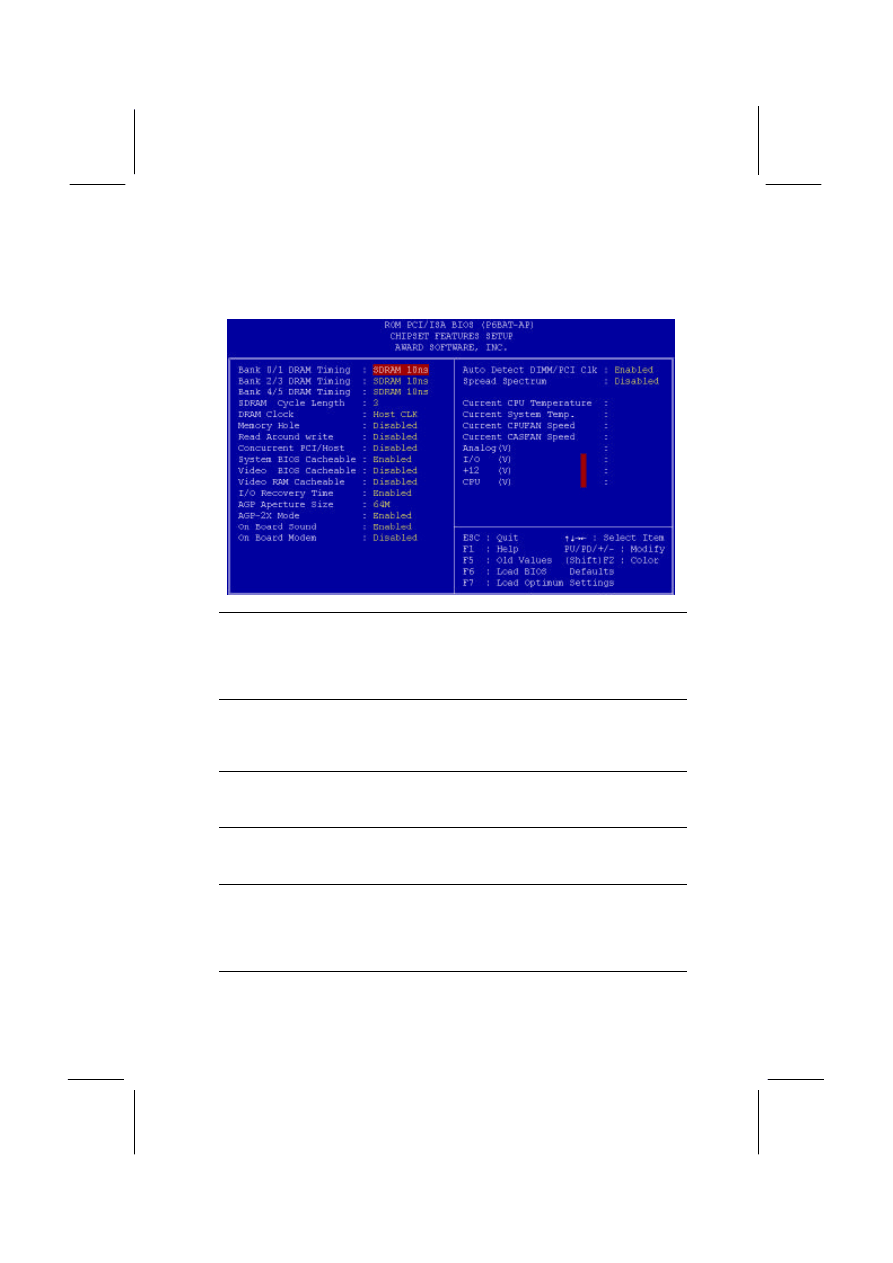
30
specifications of your hardware. If you change the values, you may
introduce fatal errors or recurring instability into your system.
Bank 0/1 DRAM Timing
Default: SDRAM 10ns
Bank 2/3 DRAM Timing
Default: SDRAM 10ns
Bank 4/5 DRAM Timing
Default: SDRAM 10ns
These items define the timing parameters for the system memory. We
recommend that you leave these items at the default values SDRAM 10ns.
SDRAM Cycle Length
Default: 3
This item sets the number of CPU cycles between SDRAM refresh. If insufficient
time is allowed, refresh may be incomplete and data can be lost. We
recommend that you leave this item at the default value.
DRAM Clock
Default: Host CLK
When this item is enabled, It allows the DRAM to work concurrently with the host
bus clock, otherwise, DRAM will work concurrently with AGP clock .
Memory Hole
Default: Disabled
This item can be used to reserve memory space for some ISA cards that require
it. We recommend that you leave this item at the default value Disabled.
Read Around write
Default: Disabled
This item optimizes the cache memory. If the system needs to read data from an
address in memory, and the write buffer holds fresh data that has not yet been
written to that address, the read can be made directly from the write buffer,
instead of the address in the main memory.
Concurrent PCI/Host
Default: Disabled
This item allows other PCI devices to work concurrently with the host PCI IDE
channel. We recommend that you leave this item at the default value Disabled.

31
System BIOS Cacheable
Default: Enabled
Video BIOS Cacheable
Default: Disabled
These items allow the video and/or system to be cached in memory for faster
execution. Wee recommend that you leave these items at the default value.
Video RAM Cacheable
Default: Disabled
This item permits the video memory to be cached for faster performance. We
recommend that you leave this item at the default value Disabled.
I/O Recovery Time
Default: Enabled
When this item is enabled, the ISA command can be extended more than the
recovery time default 3.5 SYSCLK . We recommend that you leave this item at
the default value.
AGP Aperture Size
Default: 64M
This item defines the size of the aperture for the Accelerated Graphics Port. The
aperture is a portion of the PCI memory address range dedicated for graphics
memory address space.
AGP-2x Mode
Default: Enabled
This item allows the AGP graphics adapter to operate in 2x Mode. We
recommend that you leave this item at the default value Enabled.
On Board Sound
Default: Enabled
Use this item to enable or disable the sound system that is integrated on this
mainboard.
On Board Modem
Default: Disabled
Use this item to enable or disable the fax/modem that is integrated on this
mainboard.
Auto Detect DIMM/PCI Clk
Default: Enabled
When this item is enalbed, it can be used to detect the clock whether you install
the DIMM/PCI on your mainbord or not in order to avoid the clock interference.
Spread Spectrum
Default: Disabled
When this item is enabled, it can significantly reduce the EMI (electrical magnetic
interference) that your system generates.
Right Side Items
The items on the right side of the Chipset Features option are concerned with
monitoring certain temperatures, voltages, and so on in your system. These
items do not function unless you have installed an optional system monitoring
chip on your mainboard.
Power Management Setup Option
This option displays a table of items which lets you control the power
management of the system. Modern operating systems take care of
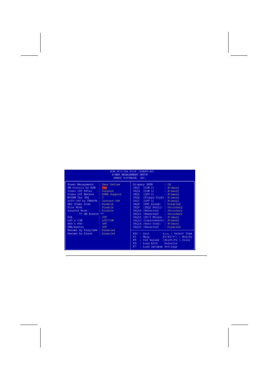
32
much of the routine power management. This mainboard supports ACPI
(advanced configuration and power interface).
This system supports three levels of power-saving modes; doze mode,
standby mode, and suspend mode. Standby mode uses less power than
doze mode and suspend mode uses the least power.
The power management in the setup utility lets you specify a timeout for
each of the power-saving modes, and a timeout for a hard disk drive
power down. A timeout, means a period of time when the system (or the
hard disk drive) is inactive. If the timeout completes, the system power-
saving mode will execute, or the hard disk drive will power down.
You can resume from the power-saving modes by carrying out any of the
activities which are enabled in the list Reload Global Timer Events. If the
hard disk has been powered down it will automatically resume to full
power when an access to the hard disk is required (this takes just a few
seconds).
Power Management
Default: User Define
This item acts like a master switch for the power-saving modes and hard disk
timeouts. If this item is set to Disabled, all the power-saving modes are disabled.
If this item is set to Max Saving, doze, standby, and suspend mode, will occur
after a timeout of 20 seconds. If this item is set to Min Saving, doze, standby,
and suspend mode will occur after a timeout of 40 minutes. If the item is set to
User Define, you can insert your own timeouts for the power-saving modes.

33
PM Control by APM
Default: Yes
Windows 95 and 98 have built-in power management capabilities called APM
(advanced power management). When you enable this item, you allow the APM
routines in Windows to operate on your system.
Video Off Option
Default: Suspend -> Off
This option defines which level of power-saving mode is required in order to
power down the video display. As a default, the video powers down in suspend
mode but not standby mode.
Video Off Method
Default: DPMS Support
This item defines how the video is powered down to save power. As a default,
this is set to DPMS Support (display power management software).
Modem Use IRQ
Default: 3
If you would like an incoming call on a modem to automatically resume the
system from suspend mode, use this item to specify the interrupt request line
(IRQ) that is used by the modem.
Soft-Off by PWRBTN
Default: Instant-Off
Under ACPI (advanced configuration and power interface) the system can be
turned off mechanically (by the power button) or it can undergo a software power
off. If the system has been turned off by software, the system can be resumed by
a LAN, MODEM or ALARM wake up signal. This item allows you to define a
software power off using the power button. If the value is set to Instant-Off, the
power button will automatically cause a software power off. If the value is set to
Delay 4 Sec. the power button must be held down for a full four seconds to
cause a software power off.
HDD Power Down
Default: Disabled
You can use this item to set a timeout for a hard disk powerdown. You can set a
time from 1 to 15 minutes. If the hard disk is inactive for the time specified, it will
power down. It will automatically return to full power when it is next accessed.
Doze Mode
Default: Disabled
If you have selected User Define for the Power Management item, you can set
this item to a selection of timeouts from 20 seconds to 40 minutes.
Suspend Mode
Default: Disabled
If you have selected User Define for the Power Management item, you can set
this item to a selection of timeouts from 20 seconds to 40 minutes.
VGA
Default: OFF
When this item is enabled, any activity on the graphics system can reset power-
saving mode timeouts to zero, or resume the system from a power saving mode.
LPT & COM
Default: LPT/COM
When this item is enabled, it defines system activities which can reset power-
saving mode timeouts to zero, or resume the system from a power saving mode.
This item is for transmissions through the serial or parallel ports.

34
HDD & FDD
Default: ON
When this item is enabled, it defines system activities which can reset power-
saving mode timeouts to zero, or resume the system from a power saving mode.
This item is for hard disk and/or diskette drive activity.
DMA/master
Default: OFF
When this item is enabled, it defines system activities which can reset power-
saving mode timeouts to zero, or resume the system from a power saving mode.
This item is activity through the system DMA controller.
Wake Up On LAN
Default: Enabled
This item allows you to enable or disable the LAN wake up function that is a
feature of this mainboard. When enabled, traffic through a network will resume
the system from any of the power-saving modes.
Modem Ring Resume
Default: Disabled
This item allows you to enable or disable the modem wakeup function that is a
feature of this mainboard. When enabled, traffic through a fax/modem will
resume the system from any of the power-saving modes.
RTC Alarm Resume
Default: Disabled
This item lets you install a wakeup alarm, which resumes the system from a
power saving mode at a fixed date and time. When the item is enabled, new
items appear which allow you to set the date and time of the alarm.
Primary INTR
Default: On
This item acts like a master switch for all the interrupt items that follow. If this
item is set to ON, the all the following interrupts can be manually configured to
act as resets for the power saving timeouts. If this item is set to OFF, then all the
following interrupt items cannot be used to reset the power saving timeouts.
IRQX
These interrupt events can act as triggers to reset the power saving timeouts or
other system maintenance tasks. If you set an interrupt event to Primary, any
activity on that interrupt will reset the timeouts that use the primary timer (e.g. the
power saving modes). If you set an interrupt to Secondary, then any activity on
the interrupt will reset those timeouts that use the secondary timer (usually
background maintenance tasks). If you set an interrupt event to Disabled, any
activity on the interrupt will not reset the timeouts.
PNP/PCI Configuration Option
This option displays a table of items that configures how PNP (Plug and
Play) and PCI expansion cards operate in your system.

35
PNP OS Installed
Default: No
If you have installed a Plug and Play operating system such as Windows 95 or
98, you can change this item to Yes. When the item is set to Yes you can use
the Device Manager utility in the operating system to make changes to the
configuration of expansion cards.
Resources Controlled By
Default: Manual
You should leave this item at the default Manual. If you find that you cannot get a
particular expansion card to work properly, you might be able to solve the
problem by changing this item to Manual, and defining the characteristics of the
card in the new items which appear.
In the default Manual, the display will list a series of items that allow you to
define the assignments of the system interrupt lines (IRQs) and Direct Memory
Access (DMA) channels. As a default, these items are set to PCI/ISA PnP. If you
install an ISA-bus card that does not support PNP, and it requires a special IRQ
and DMA, you can modify the list of assignments. Change the values of the IRQ
and DMA that are required to Legacy ISA.
Reset Configuration Data
Default: Disabled
If you enable this item and restart the system, any PNP configuration data stored
in the BIOS setup will be cleared from memory. New updated configuration data
will be created.
Assign IRQ for USB
Default: Enabled
When this item is enabled, the system will assign an IRQ to the USB ports.

36
Load BIOS Defaults Option
This option displays a dialog box which allows you to install BIOS
defaults for all appropriate items in the whole setup utility. Press the Y
key and then the Enter key to install the defaults. Press the N key and
then Enter to not install the defaults. The BIOS defaults do not place
great demands on the system and are generally very stable. If your
system is not running correctly, you might like to install the BIOS defaults
as a first step in getting your system working properly again. If you only
want to install BIOS defaults for a specific option, select and display the
option, and press the F6 key.
Load Setup Defaults Option
This option displays a dialog box which allows you install setup defaults
for all appropriate items in the whole setup utility. Press the Y key and
then the Enter key to install the defaults. Press the N key and then Enter
to not install the defaults. The setup defaults can place some demands
on the system that are greater than the performance level of the
components, such as the processor and the memory. You could cause
fatal errors or recurring instability of you install the optimum defaults
when your hardware does not support it. If you only want to install
optimum settings defaults for a specific option, select and display that
option, and then press the F7 key.
Integrated Peripherals Option
This option displays a list of items which defines the operation of some
peripheral items on the system’ s input/output ports.

37
OnChip IDE Channel0
Default: Enabled
OnChip IDE Channel1
Default: Enabled
You can use these items to enable or disable the primary (0) and secondary (1)
IDE channels that are built into this mainboard. When one or both channels are
enabled, items appear which allow you to set the PIO (programmable
input/output) mode and the UltraDMA mode for master and slave devices on the
channels. We recommend that you leave these items at the default value Auto.
The system will then automatically use the best performance PIO mode and
UltraDMA mode for each device.
IDE Prefetch Mode
Default: Enabled
The built-in IDE drive interfaces support IDE prefetching for faster drive accesses.
If you use an alternative IDE interface (on an expansion card), disable this field if
the alternate IDE interface does not support prefetching.
IDE HDD Block Mode
Default: Enabled
IDE hard disks can deliver better performance if they use block mode transfer.
Most modern hard disk drives support block mode transfers so this item is
Enabled as a default.
IDE Primary Master PIO
Default: Auto
IDE Primary Slave PIO
Default: Auto
IDE Secondary Master PIO
Default: Auto
IDE Secondary Slave PIO
Default: Auto
Each IDE channel supports a master device and a slave device. These four
items let you assign which kind of PIO (Programmed Input/Output) is used by
IDE devices. You can choose Auto, to let the system auto detect which PIO
mode is best, or you can install a PIO mode from 0-4.

38
IDE Primary Master UDMA
Default: Auto
IDE Primary Slave UDMA
Default: Auto
IDE Secondary Master UDMA
Default: Auto
IDE Secondary Slave UDMA
Default: Auto
Each IDE channel supports a master device and a slave device. This
motherboard supports UltraDMA. UltraDMA technology provides faster access to
IDE devices. If you install a device which supports UltraDMA, change the
appropriate item on this list to Auto. You may have to install the UltraDMA driver
supplied with this motherboard in order to use an UltraDMA device.
Init Display First
Default: PCI Slot
Use this item to define if your graphics adapter is installed in one of the PCI slots,
or if you have installed an AGP graphics adapter into the AGP slot.
Power On Function
Default: Hot KEY
KB Power ON Password
Default: [Enter]
Hot Key Power ON
Default: Ctrl-F12
The Power On Function item allows you to power on the system by pressing hot-
keys, or typing in a password. If you choose Password, you can use the item KB
Power On Password to install a power on password. If you set this item to Hot
Key, you can then use the item Hot Key Power On to choose which hot keys are
installed.
KBC input clock
Default: 8 MHz
This item lets you set a frequency for the input clock of the keyboard controller.
Leave this item at the default value 8 MHz.
Onboard FDC Controller
Default: Enabled
This item enables or disables the floppy diskette drive controller built into this
mainboard.
Onboard Serial Port 1
Default: 3F8/IRQ4
This item lets you disable the built-in serial port 1, or enable it by assigning an
I/O address and an Interrupt Request Line (IRQ).
Onboard Serial Port 2
Default: 2F8/IRQ3
This item lets you disable the built-in serial port 2, or enable it by assigning an
I/O address and an Interrupt Request Line (IRQ).
UART Mode Select
Default: Normal
This item defines the operation of serial port 2. In the default Normal setting,
serial port 2 is assigned to the connector on the mainboard. If you have installed
an optional infrared port, you must change the setting of this item to either IrDA,
or ASKIR. These settings will disable the mainboard serial port connector and
assign serial port 2 to the infrared device. IrDA prepares the port to receive
infrared communications using the IrDA serial infrared standard. ASKIR prepares
the port to receive infrared communications using the ASK serial infrared
standard. The ASK standard is supported my many devices made by the Sharp
Corporation. If you have selected an IR mode, you can use the following two
items RxD, TxD Active, and IR transmission delay to set the parameters of the

39
infrared port. See the documentation for the infrared port for information on these
items.
Onboard Parallel Port
Default: 378/IRQ7
This item lets you disable the built-in parallel port, or enable it by assigning an
I/O address and an Interrupt Request Line (IRQ).
Parallel Port Mode
Default: ECP + EPP
This item defines the operation of the parallel port. As a default it is set to ECP +
EPP. If you are connected to a parallel device that supports the higher-
performance EPP (enhanced parallel port) or the ECP (extended capabilities port)
make the appropriate changes to this item. If you change the parallel port to EPP
or ECP, new items appear that let you configure the EPP and ECP modes.
OnChip USB
Default: Enabled
This mainboard has a built-in USB (universal serial bus) port so you should leave
this item at the default value Enabled.
USB Keyboard Support
Default: Disabled
If you connect a USB keyboard to your system, enable this item.
Supervisor Password and User Password
These two items can be used to install a Supervisor Password and a
User Password. If you log on as Supervisor, you have full access to the
system, and you can restrict the permissions granted to someone who
logs on as User. For example, a Supervisor can restrict a User from
entering the setup utility.
To install a Supervisor or User Password, follow these steps:
1. Highlight the item Supervisor/User password on the main menu and
press Enter.
2. The password dialog box will appear.
3. If you are installing a new password, carefully type in the password.
You cannot use more than 8 characters or numbers. The password
will differentiate between upper case and lower characters. Press
Enter after you have typed in the password. If you are deleting a
password that is already installed just press Enter when the
password dialog box appears.
4. The system will ask you to confirm the new password by asking you
to type it in a second time. Carefully type the password again and
press Enter, or just press Enter if you are deleting a password that
is already installed.
5. If you typed the password correctly, the password will be installed.

40
IDE HDD Auto Detection Option
This item automatically detects and installs any hard disk drives installed
on the primary and secondary IDE channel. Most modern drives can be
detected. If you are using a very old drive that can’ t be detected, you can
install it manually using the Standard CMOS Setup option.
Setup will check for two devices on the primary IDE channel and then
two devices on the secondary IDE channel. At each device, the system
will flash an N in the dialog box. Press Enter to skip the device and
proceed to the next device. Press Y, then Enter to tell the system to
auto-detect the device.
Save And Exit Setup Option
Highlight this item and press Enter to save the changes that you have
made in the setup utility and exit the setup program. When the Save and
Exit dialog box appears, press Y to save and exit, or press N to return to
the setup main menu.
Exit Without Saving Option
Highlight this item and press Enter to discard any changes that you have
made in the setup utility and exit the setup program. When the Exit
Without Saving dialog box appears, press Y to discard changes and exit,
or press N to return to the setup main menu.
Wyszukiwarka
Podobne podstrony:
bb5 chap3
chap3 forward kinematics
chap3
mcga shs capt guide chap3
bb5 chap3
Chap3
Filters Duch Chap3
więcej podobnych podstron