
121
In This Chapter
8
Creating Sketched Features
Features are the parametric building blocks of parts. By
creating and adding features you define the shape of
your part. Because features are parametric, any changes
to them are automatically reflected when the part is
updated.
In Autodesk
®
Mechanical Desktop
®
, there are three
types of features—sketched, work and placed.
In this tutorial, you learn to create and modify sketched
features. In chapter 4, you learn about work features.
■
Extruded features
■
Loft features
■
Revolved features
■
Face splits
■
Sweep features

122
|
Chapter 8
Creating Sketched Features
Key Terms
Term
Definition
base feature
The first feature you create. As the basic element of your part, it represents its
simplest shape. All geometry you create for a part depends on the base feature.
Boolean modeling
A solid modeling technique in which two solids are combined to form one
resulting solid. Boolean operations include cut, join, and intersect. Cut subtracts
the volume of one solid from the other. Join unites two solid volumes. Intersect
leaves only the volume shared by the two solids.
consumed sketch
A sketch used in a feature, for example, an extruded profile sketch. The sketch is
consumed when the feature is created.
cubic loft
A feature created by a gradual blending between two or more planar sections.
draft angle
An angle applied parallel to the path of extruded, revolved, or swept surfaces or
parts. A draft angle is used to allow easy withdrawal from a mold or easy insertion
into a mated part.
extrude
In part modeling, to create a geometric sketch defined by a planar profile
extended along a linear distance perpendicular to the profile plane.
feature
An element of a parametric part model. You can create extruded features,
revolved features, loft features, and swept features using profiles and paths. You
can also create placed features like holes, chamfers, and fillets. You combine
features to create complete parametric part models.
helical sweep
A geometric feature defined by the volume from moving a profile along a 3D
path about a work axis.
linear loft
A feature created by a linear transition between two planar sections.
lofted feature
A parametric shape created from a series of sketches defining the cross-sectional
shape of the feature at each section.
revolve
In part modeling, to create a feature by revolving a profile about an axis of
revolution.
sketch plane
A temporary drawing surface that corresponds to a real plane on a feature. It is an
infinite plane with both X and Y axes on which you sketch or place a feature.
sketched feature
A three-dimensional solid whose shape is defined by constrained sketches and
located parametrically on a part. Sketched features are extrudes, lofts, revolves,
sweeps, or face splits.
sweep
A geometric sketch feature defined by the volume from moving a profile along a
path.
swept profile
A special parametric sketch used to create a swept feature from the cross section
of a profile.

Basic Concepts of Sketched Features
|
123
Basic Concepts of Sketched Features
Features are the building blocks you use to create and shape a part. Because
they are fully parametric, they can easily be modified at any time.
The first feature in a part is called the base feature. As you add more features,
they can be combined with the base feature or each other to create your part.
Boolean operations, such as cut, join, and intersect, can be used to combine
features after a base feature has been created.
You create a sketched feature from a profile, which is an open or closed
parametric sketch that has been solved. You can also create a feature from
a text-based sketch. In most cases, you fully constrain the profile before
you create a feature. Because a sketch is parametric, you can easily modify
it to change the shape of the feature. When you update your part, the
changes you made are displayed automatically.
Sketched features include extrusions, lofts, revolutions, sweeps, and emboss-
ing. Face splits are also considered sketched features, but they are created by
splitting a part face using an existing face, a work plane, or a split line. If you
choose the split line method, you are using a sketched feature to split the
face.
In this tutorial you learn how to create and edit sketched features. Later you
learn how to create and edit work features and placed features.
Open the file s_feat.dwg in the desktop\tutorial folder.
NOTE
Back up the tutorial drawing files so you still have the original files if you
make a mistake. See “Backing up Tutorial Drawing Files” on page 40.
124
|
Chapter 8
Creating Sketched Features
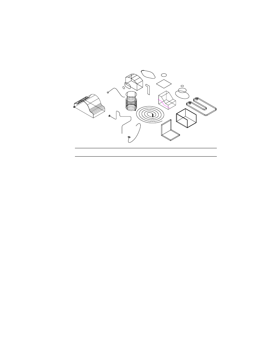
The drawing file includes fifteen parts which contain the geometry you need
to create the sketched features in this section.
NOTE
For clarity, the work features are not shown.
First, you create an extruded feature.
Creating Extruded Features
Extrusions are the most common sketched features. An extruded feature can
be created from a closed profile, an open profile, or a text-based profile.
Extruding Closed Profiles
A closed profile is used to create a base feature, or in Boolean modeling to cut,
intersect, and join with other features.
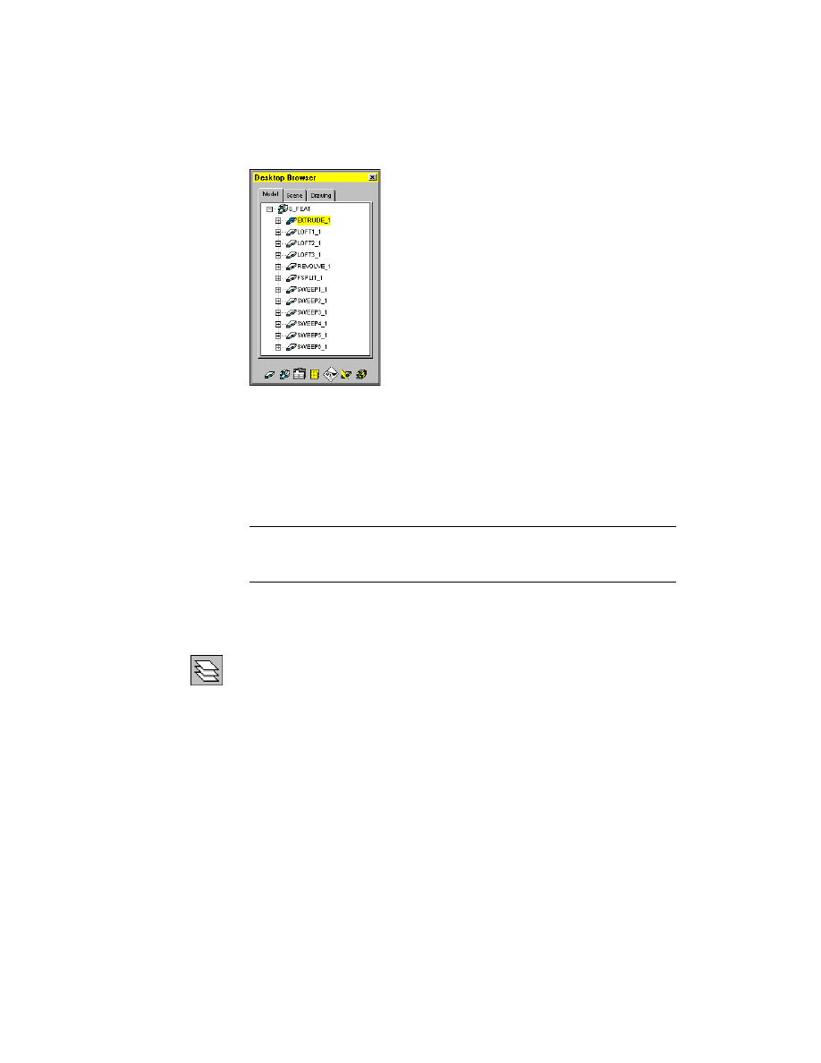
In the first exercise, you use the part EXTRUDE_1. Activate the part, and
expand the hierarchy of EXTRUDE_1.
To activate a part
Browser
Double-click EXTRUDE_1.
Click the plus sign in front of EXTRUDE_1 to expand the
hierarchy.
Creating Extruded Features
|
125
Clear the visibility of the other parts, and display the dimensions and work
features of the active part.
To turn off the visibility of multiple parts
Browser
Select EXTRUDERIB_1, then hold down
SHIFT
as you
select BEND_1. Right-click the selected block and choose
Visible.
NOTE
Because most of the parts do not contain features yet, you cannot use
the toolbutton, menu, or command methods to make the part instances
invisible.
Click the plus sign in front of EXTRUDE_1 to expand the hierarchy.
To thaw dimension and work layers
Desktop Menu
Assist ➤ Format ➤ Layer
The Layer Properties Manager dialog box is displayed.
In the AM_PARDIM layer, select the On icon and the Freeze icon to unthaw
the layer. Repeat for the
AM_WORK
layer.
Choose OK to exit the dialog box.
The parametric dimensions and work features for each part are now visible.
126
|
Chapter 8
Creating Sketched Features
To zoom in to a part
Browser
Right-click EXTRUDE_1, and choose Zoom to.
The EXTRUDE_1 part is positioned on your screen.
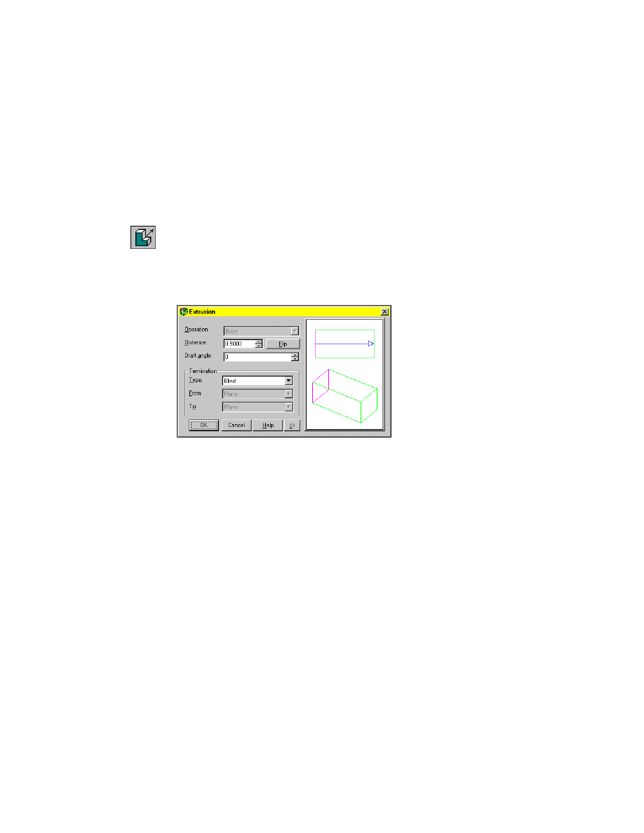
To create an extruded feature
1
Use
AMEXTRUDE
to create an extruded feature from Profile1.
Context Menu
In the graphics area, right-click and choose Sketched &
Work Features ➤ Extrude.
In the Extrusion dialog box, specify:
Distance:
Enter 0.5
Termination:
Type:
Blind
The image tile indicates the direction of the extrusion.
Choose OK.
Creating Extruded Features
|
127
The profile is extruded perpendicular to the plane of the profile.
Next, you create and constrain another profile, and extrude it to cut material
from the base feature.
To create a profile sketch
1
Change to the top view of your part.
Desktop Menu
View ➤ 3D Views ➤ Top
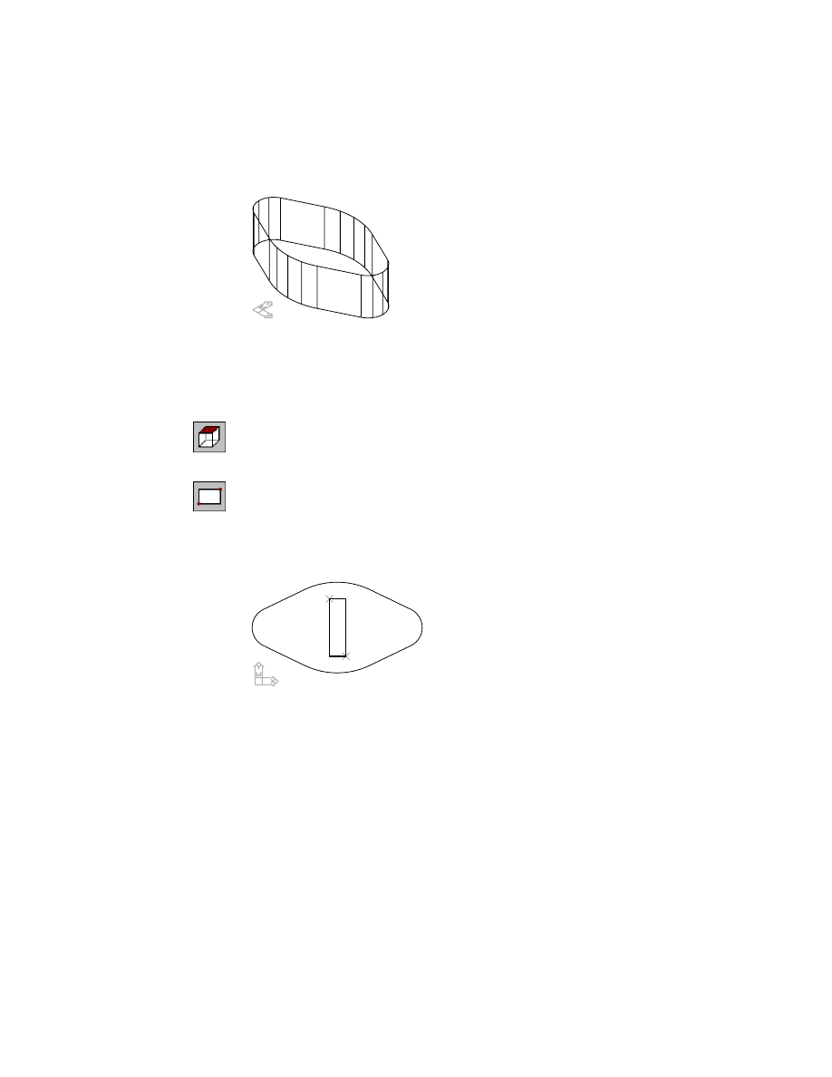
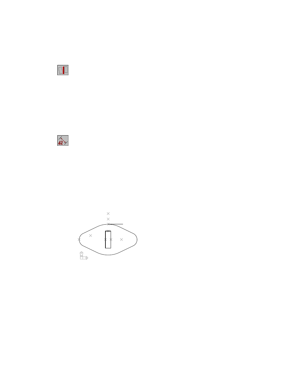
2
Use
RECTANGLE
to sketch a rectangle as shown in the following illustration,
responding to the prompts.
Context Menu
In the graphics area, right-click and choose 2D Sketching
➤ Rectangle.
Specify first corner point or [Chamfer/Elevation/Fillet/Thickness/Width]:
Specify a point (1)
Specify other corner point:
Specify a second point (2)
1
2
128
|
Chapter 8
Creating Sketched Features
3
Use
AMRSOLVESK
to solve the sketch.
Context Menu
In the graphics area, right-click and choose Sketch Solving
➤ Single Profile.
The command line indicates the number of constraints required to fully con-
strain the profile.
Solved underconstrained sketch requiring 4 dimensions or constraints.
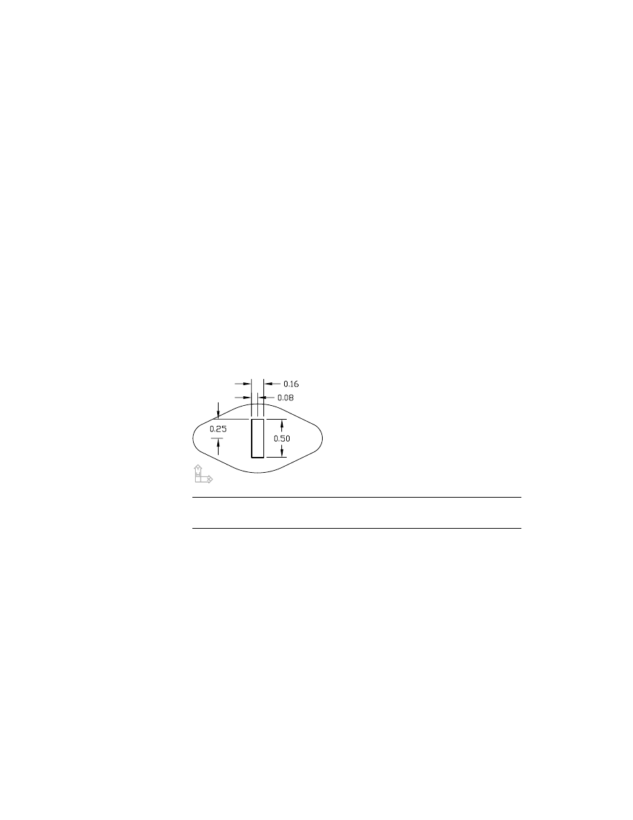
Before you extrude the profile, fully constrain it by adding four dimensional
constraints.
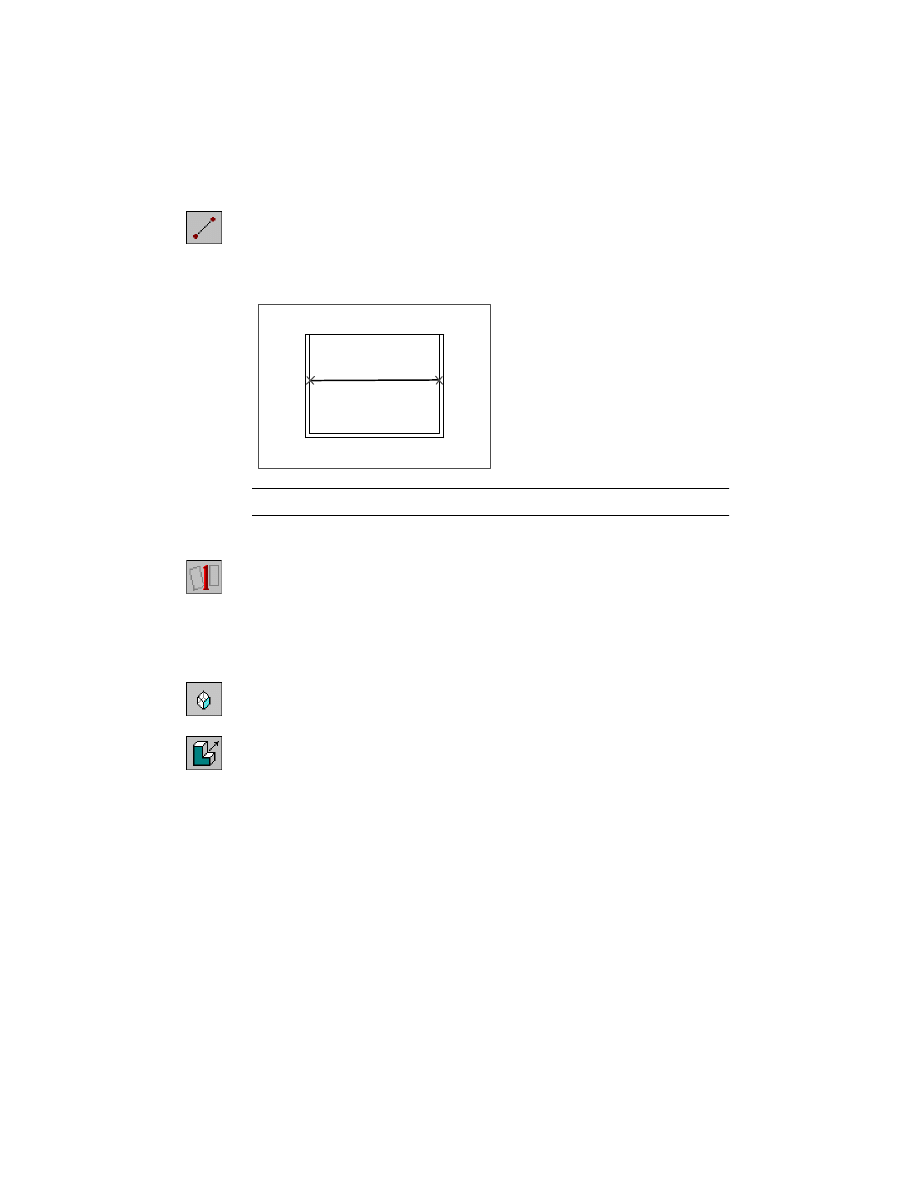
To constrain a sketch
1
Use
AMPARDIM
to add parametric dimensions to fully constrain the sketch,
responding to the prompts.
Context Menu
In the graphics area, right-click and choose Dimensioning
➤ New Dimension.
Select first object:
Specify the top edge (1)
Select second object or place dimension:
Place the dimension (2)
Enter dimension value or [Undo/Hor/Ver/Align/Par/aNgle/Ord/Diameter/pLace]
<0.1574>:
Enter .16
Solved underconstrained sketch requiring 3 dimensions or constraints.
Select first object:
Specify the top edge again (1)
Select second object or place dimension:
Specify the top arc (3)
Specify dimension placement:
Place the dimension (4)
Enter dimension value or [Undo/Hor/Ver/Align/Par/aNgle/Ord/Diameter/pLace]
<0.0730>:
Enter .08
Solved underconstrained sketch requiring 2 dimensions or constraints.
5
6
2
4
3
1
7
9
8
Creating Extruded Features
|
129
2
Continue creating the parametric dimensions.
Select first object:
Specify the right edge (5)
Select second object or place dimension:
Place the dimension (6)
Enter dimension value or [Undo/Hor/Ver/Align/Par/aNgle/Ord/Diameter/pLace]
<0.4500>:
Enter .5
Solved underconstrained sketch requiring 1 dimensions or constraints.
Select first object:
Specify the left edge (7)
Select second object or place dimension:
Specify the left arc (8)
Specify dimension placement:
Place the dimension (9)
Enter dimension value or [Undo/Hor/Ver/Align/Par/aNgle/Ord/Diameter/pLace]
<0.2430>:
Enter v
Enter dimension value or [Undo/Hor/Ver/Align/Par/aNgle/Ord/Diameter/pLace]
<0.2430>:
Enter .25
After you finish dimensioning, the following message is displayed on the
command line:
Solved fully constrained sketch.
Select first object:
Press
ENTER
Your sketch should look like this.
NOTE
For clarity, the parametric dimensions controlling Profile1 are not
shown.
Now that the profile is fully constrained, you extrude it into the base feature
to cut material from your part.
130
|
Chapter 8
Creating Sketched Features
To add an extruded feature to a part
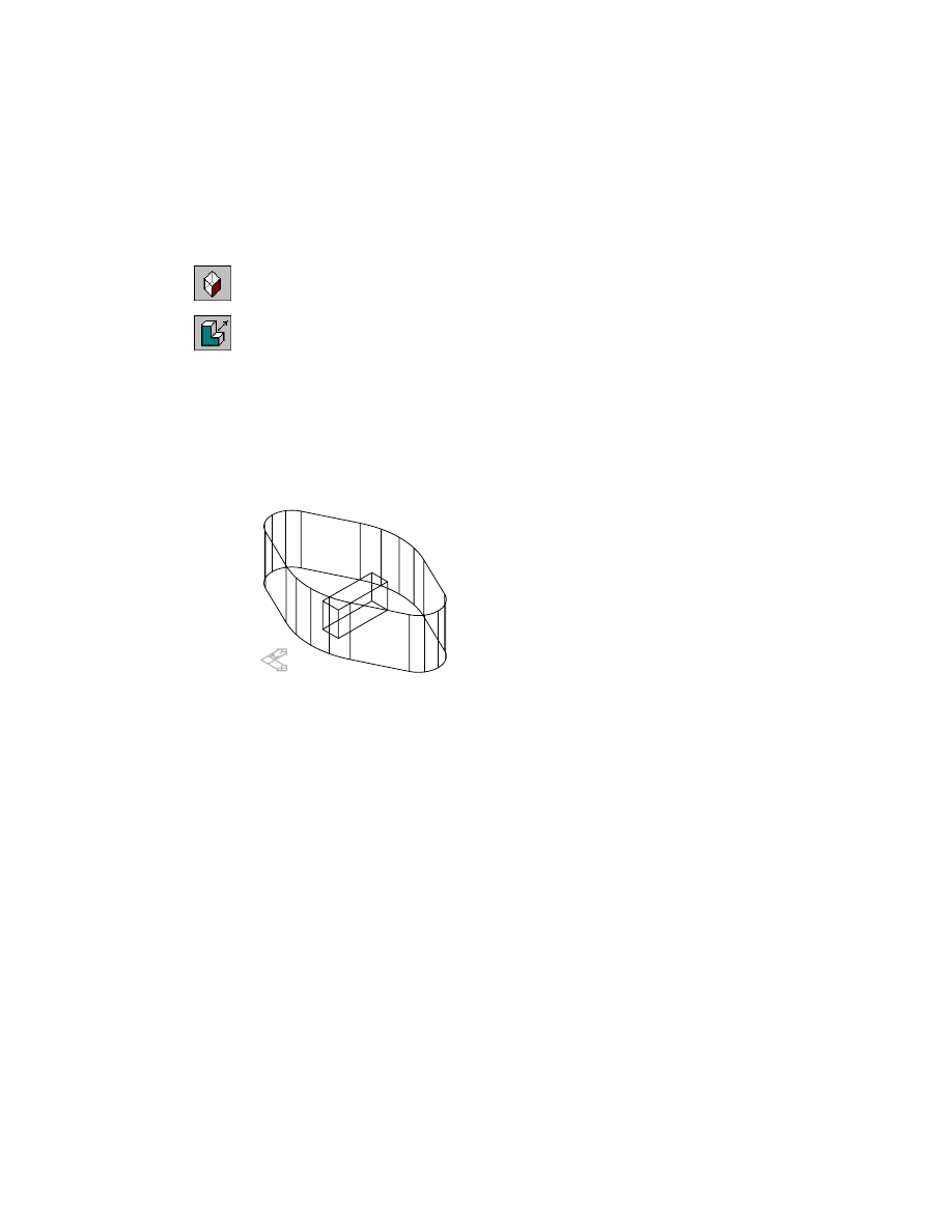
1
Change to an isometric view.
Desktop Menu
View ➤ 3D Views ➤ Front Right Isometric
2
Extrude the profile.
Context Menu
In the graphics area, right-click and choose Sketched &
Work Features ➤ Extrude.
3
In the Extrusion dialog box, specify the following:
Operation:
Cut
Distance:
Enter 0.25
Termination:
Blind
4
Choose OK to exit the dialog box.
Your part should look like this.
Save your file.
Editing Extruded Features
Because an extruded feature is controlled by parametric dimensions, you can
easily make changes to it by modifying the values of the profiled sketch, or
the extruded feature itself.
Editing Extruded Features
|
131
To modify a consumed profile
1
Expand ExtrusionBlind2 in the Browser.
2
Edit the dimensions of the profile used to define the shape of the extrusion,
responding to the prompts.
Context Menu
In the graphics area, right-click and choose Edit Features
➤ Edit.
Enter an option [Sketch/surfCut/Toolbody/select Feature] <select Feature>:
Select the cut extrusion
Enter an option [Next/Accept] <Accept>: ExtrusionBlind2:
Press
ENTER
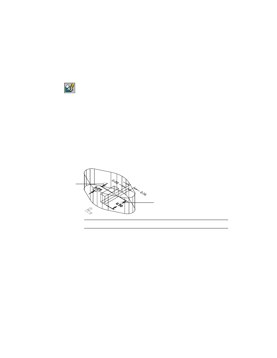
3
Choose OK to exit the Extrusion dialog box, then continue on the command
line.
Select object:
Select the 0.5 dimension (1)
Enter new value for dimension <.5>:
Enter 1
Solved fully constrained sketch.
Select object:
Select the 0.25 dimension (2)
Enter new value for dimension <.25>:
Enter .5
Solved fully constrained sketch.
Select object:
Press
ENTER
NOTE
For clarity, the taper and depth dimensions are not illustrated.
1
2
132
|
Chapter 8
Creating Sketched Features
4
Use
AMUPDATE
to update your part.
Context Menu
In the graphics area, right-click and choose Update Part.
The part now reflects the changes to the profile that controls the shape of the
extrusion you used to cut material from the part.
Next, modify the extrusion feature to change the depth of the cut.
To modify a feature
1
Select the cut extrusion to modify, responding to the prompt.
Context Menu
In the graphics area, right-click and choose Edit Features
➤ Edit.
Enter an option [Sketch/surfCut/Toolbody/select Feature] <select Feature>:
Press
ENTER,
and select the cut extrusion
Enter an option [Next/Accept] <Accept>:
Press
ENTER
2
In the Extrusion dialog box, specify a distance of .15 and Choose OK.
3
Continue on the command line.
Select object:
Press
ENTER
4
Use
AMUPDATE
to update the part.
Context Menu
In the graphics area, right-click and choose Update Part.
Editing Extruded Features
|
133
Your part should look like this.
Save your file.
Extruding Open Profiles
You extrude open profiles to create rib features and thin features.
For more information about sketching open profiles, see “Creating Open Pro-
file Sketches” on page 46.
Creating Rib Features
To create a rib feature on a part model, you sketch an open profile to shape
the rib, define the thickness of the rib, and extrude it to part surfaces.
Observe these rules when you sketch open profiles for ribs:
■
Sketch the side view of the rib.
■
The sketch can have any number of segments.
■
The ends of the sketch need not touch surfaces the rib will attach to, but
when extended must meet valid active part surfaces, without holes in the
extrusion path.
You solve the sketch to create an open profile, and apply parametric con-
straints and dimensions as with any other profile sketch.
Like other features, the rib feature can be edited and it has dependencies. If
you delete something in your model that a rib feature depends upon, such as
a face that a profile plane is based on, you delete the rib feature as well.
134
|
Chapter 8
Creating Sketched Features
In this exercise, you extrude a rib feature to two perpendicular walls of a part.
Turn off visibility for EXTRUDE_1, and make EXTRUDERIB_1 visible.
Browser
Right-click EXTRUDE_1 and choose Visible. Then right-
click EXTRUDERIB_1 and choose Visible.
Activate EXTRUDERIB_1 and position it on your screen.
Browser
Double-click EXTRUDERIB_1. Then right-click
EXTRUDERIB_1 and choose Zoom to.
In the previous exercise, you made the work feature layer visible.
To create a rib feature
1
Change to the front view so you can sketch the rib from its side.
Desktop Menu
View ➤ 3D Views ➤ Front
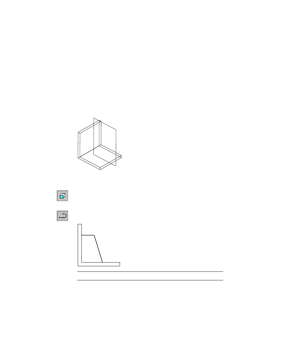
2
Use
PLINE
to sketch a rough outline of the rib, as shown in the following illus-
tration. The sketch doesn’t have to be touching the surfaces.
Context Menu
In the graphics area, right-click and choose 2D Sketching
➤ Polyline.
NOTE
For clarity, the work plane is not shown.
Editing Extruded Features
|
135
3
Use AMPROFILE to solve the sketch, responding to the prompt.
Context Menu
In the graphics area, right-click and choose Sketch Solving
➤ Single Profile.
Select part edge to close the profile <open profile>:
Press
ENTER
An icon for the open profile is displayed in the Browser.
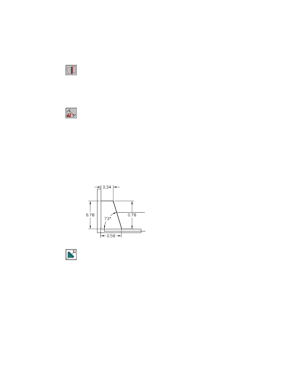
4
Use
AMPARDIM
to add an angular dimension between the lower wall and the
lower section of the rib, responding to the prompts.
Context Menu
In the graphics area, right-click and choose Dimensioning
➤ New Dimension.
Select first object:
Specify a point on the rib (1)
Select second object or place dimension:
Specify a point on the lower wall (2)
Specify dimension placement:
Specify a point to place the dimension
Enter dimension value or [Undo/Hor/Ver/Align/Par/aNgle/Ord/Diameter/pLace]
<71>:
Enter a value of 73
Select first object:
Specify the next dimension to add
Continue adding dimensions, as shown in the illustration, to fully constrain
the open profile sketch.
Solved fully constrained sketch.
Select first object:
Press
ENTER
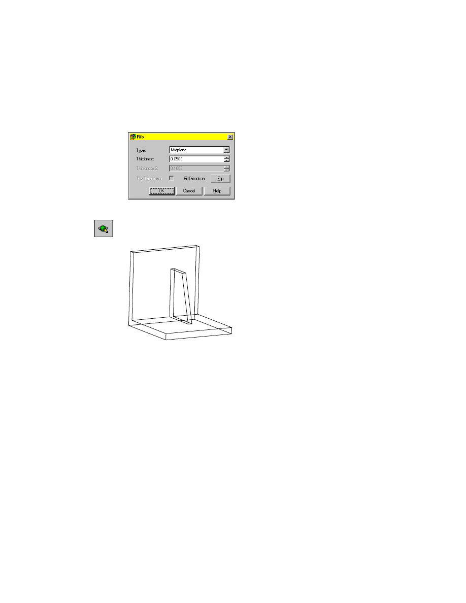
5
Use
AMRIB
to create the rib.
Browser
In the Browser, right-click the open profile icon, and
choose Rib.
1
2
136
|
Chapter 8
Creating Sketched Features
In the Rib dialog box, specify:
Type:
Midplane
Thickness:
.05
Choose OK.
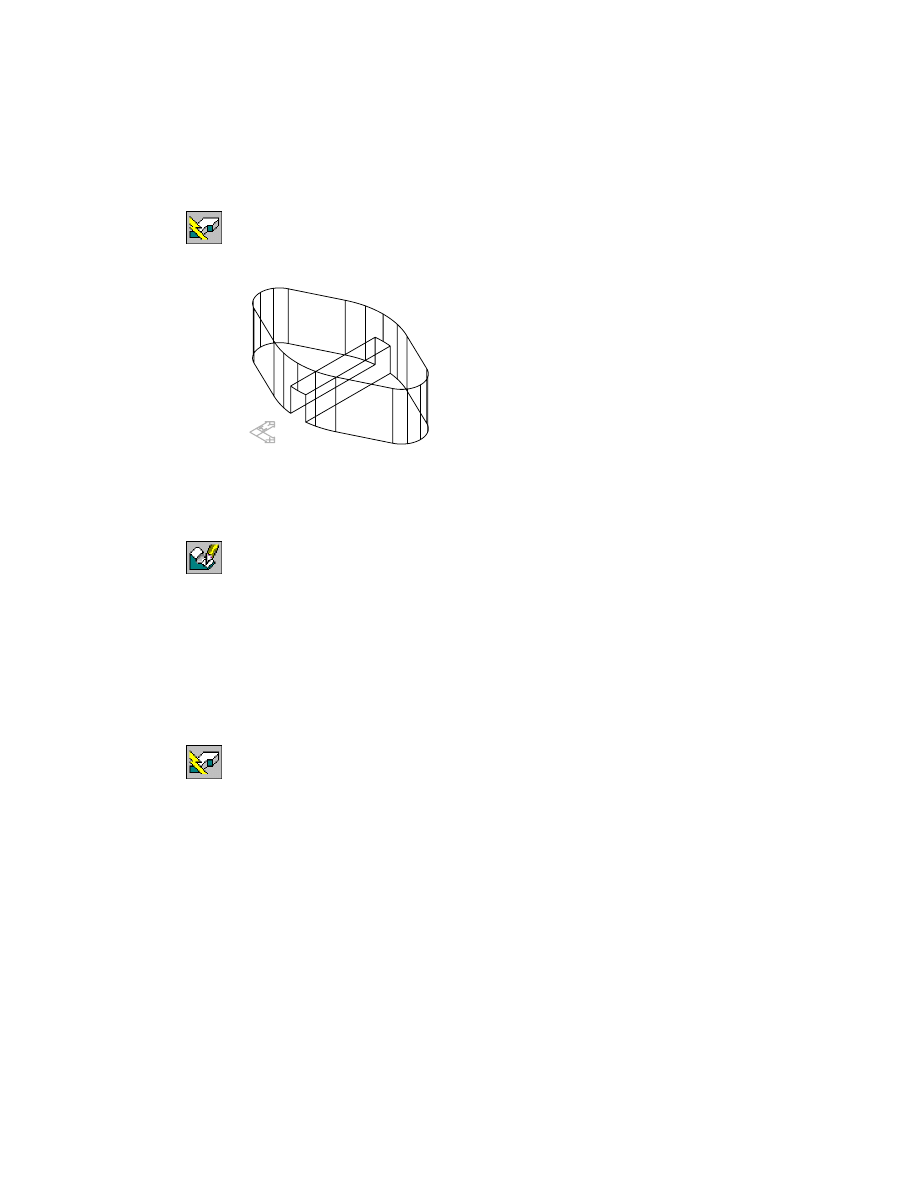
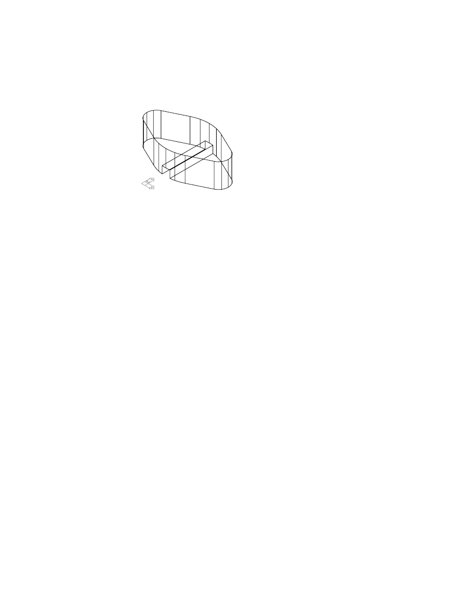
6
Use
3DORBIT
to rotate your part so you can see the rib feature.
Your part should look like this.
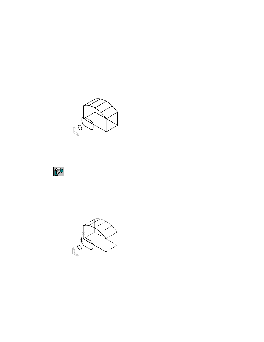
Creating Thin Features
To create a thin feature, you sketch an open profile and extrude it to part sur-
faces. When you extrude an open profile, the Extrusion dialog box includes
the options for defining a thin wall feature. When you sketch open profiles
for thin features
■
Sketch must be an open profile from the front view
■
Sketch is extruded normal to the sketch plane
■
Ends of the open profile need not touch surfaces, but when extended must
meet valid active part surfaces, without holes in the extrusion path
For more information about sketching open profiles, see “Creating Open Profile
Sketches” on page 46.
Editing Extruded Features
|
137
In this exercise, you create a thin wall in a shell. In the Browser, turn off
visibility for EXTRUDERIB_1, and make EXTRUDETHIN_1 visible.
Browser
Right-click EXTRUDERIB_1 and choose Visible. Then
right-click EXTRUDETHIN_1 and choose Visible.
Activate EXTRUDETHIN_1 and position it on your screen.
Browser
Double-click EXTRUDETHIN_1. Then right-click
EXTRUDETHIN_1 and choose Zoom to.
To create a thin feature
1
Use AMWORKPLN to create a work plane for the profile sketch.
Context Menu
In the graphics area, right-click and choose Sketched &
Work Features ➤ Work Plane.
In the Work Plane dialog box, specify:
1st Modifier:
Planar Parallel
2nd Modifier:
Offset
Offset:
Enter .75
Choose OK.
Select work plane, planar face or [worldXy/worldYz/worldZx/Ucs]:
Select the back face of the shell
Enter an option [Next/Accept] <Accept>:
Press
ENTER
Enter an option [Flip/Accept] <Accept>:
Flip to point arrow to back face, or press
ENTER
Select edge to align X axis or [Flip/Rotate/Origin] <Accept>:
Press
ENTER
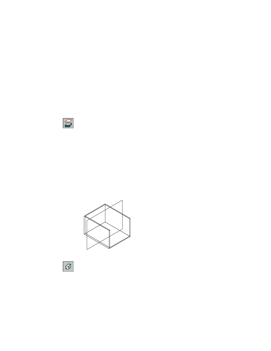
2
Change to the Right view to sketch the thin feature.
Desktop Menu
View ➤ 3D Views ➤ Right
138
|
Chapter 8
Creating Sketched Features
3
Use
LINE
to sketch the thin feature.
Context Menu
In the graphics area, right-click and choose 2D Sketching
➤ Line
Specify first point:
Specify the start point of the line (1)
Specify next point or [Undo]:
Specify the end point of the line (2) and press
ENTER
NOTE
Turn OSNAP off so that you will not snap to the back face when you pick.
4
Use
AMRSOLVESK
to solve the sketch, responding to the prompt.
Context Menu
In the graphics area, right-click and choose Sketch Solving
➤ Single Profile.
Select part edge to close the profile <open profile>:
Press
ENTER
In the Browser, an open profile icon is displayed.
5
Change to the front right isometric view to extrude the profile.
Desktop Menu
View ➤ 3D Views ➤ Front Right Isometric
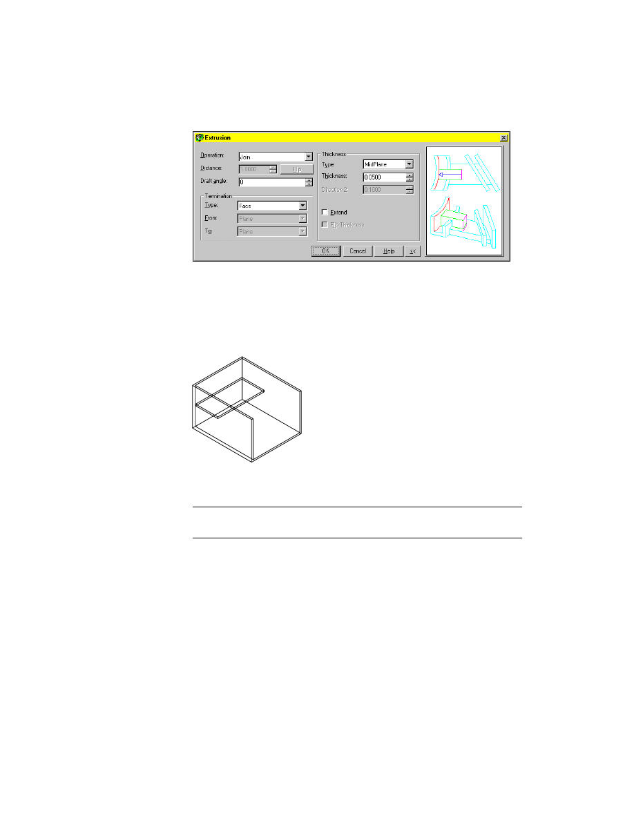
6
U
SE
AMEXTRUDE
to extrude the open profile.
Context Menu
In the graphics area, right-click and choose Sketched &
Work Features ➤ Extrude.
In the Extrusion dialog box, specify
Operation:
Join
Termination: Type:
Face
Thickness: Type:
Midplane
Thickness:
Enter .05
1
2
Editing Extruded Features
|
139
Choose OK.
7
Respond to the prompt:
Select Face:
Select the back face of the shell and press
ENTER
Enter an option [Next/Accept] <Accept>:
Press
ENTER
Your part should look like this.
A thin wall is created with equal thickness on each side of the profile. In the
Browser, an icon is displayed for the thin extrusion.
NOTE
When you extrude an open profile, the Extrusion dialog box contains
options for defining a thin feature.
Save your file with a new name so you can use the same shell part for the next
exercise.
140
|
Chapter 8
Creating Sketched Features
Creating Emboss Features
Emboss features are text sketch profiles extruded on part models. A text
sketch profile is one line of text displayed in a rectangular boundary.
To create a text sketch profile, you define a font and a style, and enter one
line of text. Then you place the text on an active sketch plane on your part,
and extrude it to emboss the surface of your part with the text.
Delete the thin extrusion from your shell part.
Browser
Right-Click ThinExtrusionToFace1 and choose Delete.
Highlighted features will be deleted. Continue? [Yes/No] <Yes>:
Press
ENTER
Change to the Front view to create the emboss feature.
Desktop Menu
View ➤ 3D Views ➤ Front
To create an emboss feature
1
Use
AMWORKPLN
to create a work plane for the text sketch.
Context Menu
In the graphics area, right-click and choose Sketched &
Work Features ➤ Work Plane.
In the Work Plane dialog box, specify:
1st Modifier:
On Edge/Axis
2nd Modifier:
Planar Parallel
Choose OK.
2
Respond to the prompts:
Select work axis, straight edge or [worldX/worldY/worldZ]:
Select the top edge of the shell
Select work plane, planar face or [worldXy/worldYz/worldZx/Ucs]:
Select the front face of the shell and press
ENTER
Select edge to align X axis or [Flip/Rotate/Origin] <Accept>:
Press
ENTER
NOTE
Verify that
CMDDIA
is set to 1 so that the Text Sketch dialog box will be
displayed. On the command line, enter
CMDDIA
, then enter 1.
3
Use
AMTEXTSK
to create a text sketch profile.
Command
AMTEXTSK
Editing Extruded Features
|
141
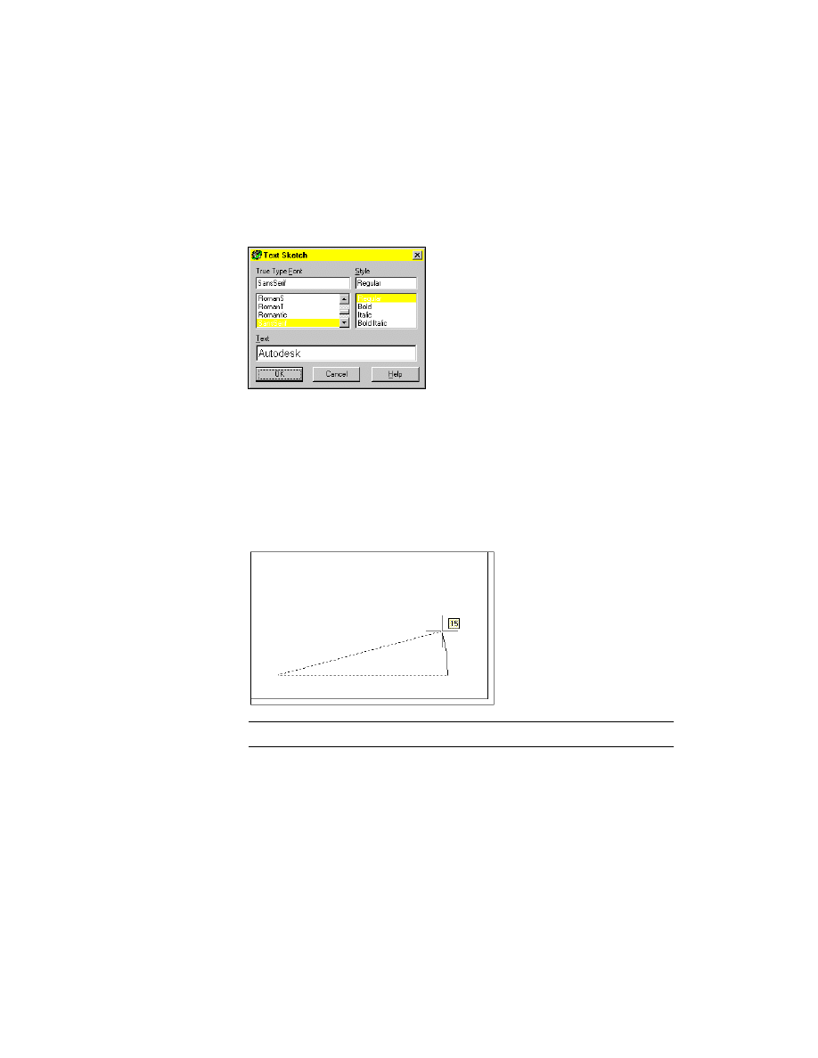
In the Text Sketch dialog box, specify:
True Type Font:
Sans Serif
Style:
Regular
Text:
Enter Autodesk
Choose OK.
4
Define a location for the text sketch with a rotation angle of 15, responding
to the prompts.
Specify first corner:
Specify a point in the lower left corner of the shell
Specify opposite corner or [Height/Rotation]:
Enter r and press
ENTER
Specify second angle endpoint or [Direction] <0>:
Move the cursor to the right and specify a rotation angle of 15
Hold the cursor in one location momentarily to display the angle dimension.
NOTE
For clarity, the work plane is not shown.
Continue on the command line.
Specify opposite corner or [Height/Rotation]:
Specify a point for the height
142
|
Chapter 8
Creating Sketched Features
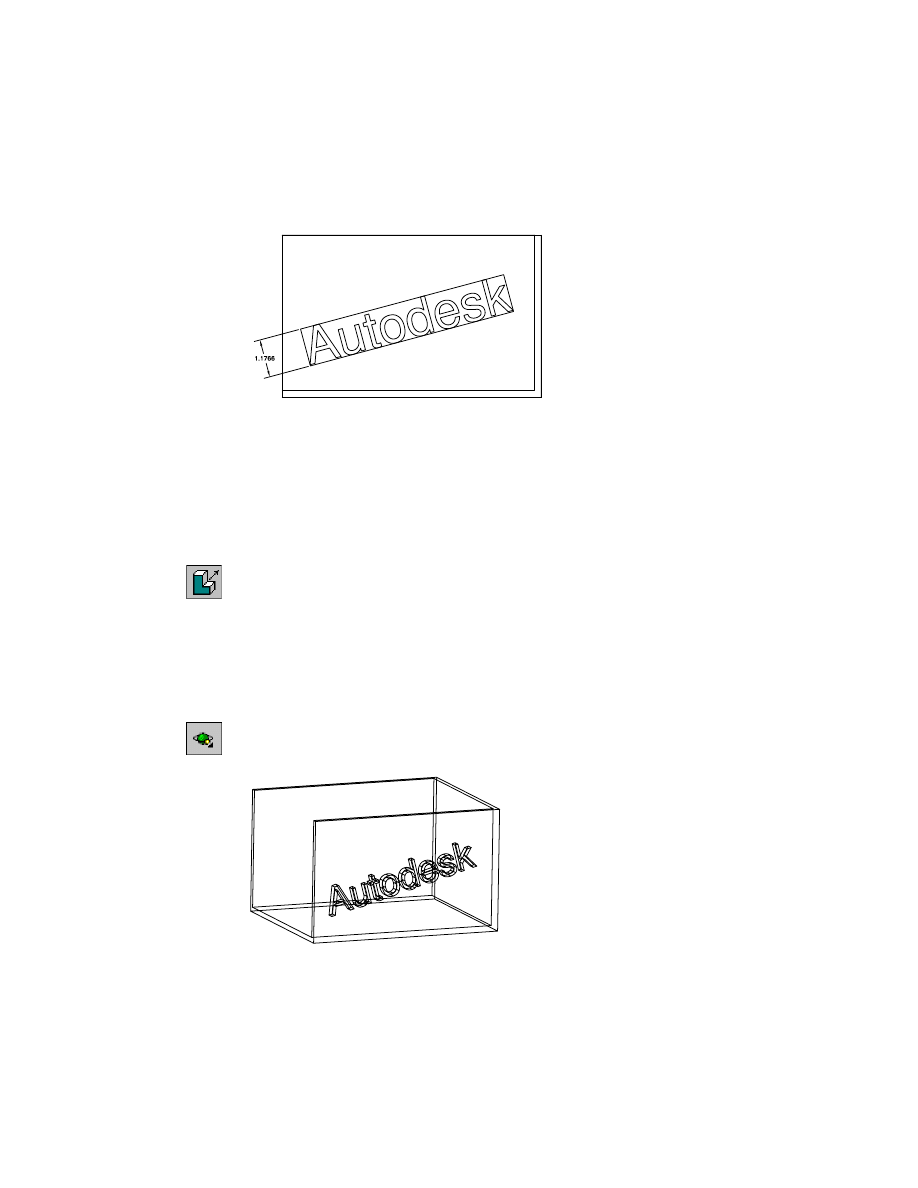
As you move the cursor, the rectangular border adjusts to accommodate the
size of the text.
In the Browser, an icon is displayed for the text sketch.
You can change the parametric dimension for the height, and you can control
the placement of the text object with typical 2D constraints and parametric
dimensions between the rectangular boundary and other edges or features on
your part.
After the text sketch is positioned on the part, you can extrude it.
5
Use
AMEXTRUDE
to extrude the text sketch.
Browser
Right-click the text sketch icon and choose Extrude.
In the Extrusion dialog box, specify:
Operation:
Join
Distance:
Enter .5
Termination: Type:
Blind
Choose OK.
6
Use
3DORBIT
to rotate your part so you can see the emboss feature.
Toolbutton
Your part should look like this.
Creating Loft Features
|
143
Editing Emboss Features
You can edit the text in an emboss feature using the Text Sketch dialog box
before the text sketch is consumed. After a text sketch is consumed by a fea-
ture, you can edit the feature dimensions or the sketch font and style.
Creating Loft Features
You create loft features by defining a series of cross sections through which
the feature is blended. Lofts may be linear or cubic. Both types can be created
with existing part faces as the start and end sections.
Creating Linear Lofts
A linear loft is a feature created by a linear transition between two planar
sections.
First, activate the next part in your drawing.
To activate a part
1
Make LOFT1_1 visible.
Browser
Right-click LOFT1_1 and choose Visible.
NOTE
Because LOFT1_1 does not contain any features, you cannot use the
toolbutton, menu, or command methods to make it visible.
2
Activate LOFT1_1.
Browser
Right-click LOFT1_1 and choose Activate Part
3
Make EXTRUDE_1 invisible.
Browser
Right-click EXTRUDE_1 and choose Visible.
4
In the Desktop Visibility dialog box, select the Assembly tab.
5
Choose Select and continue on the command line.
Select assembly objects to hide:
Select EXTRUDE_1
Select assembly objects to hide:
Press
ENTER
6
Choose OK to exit the dialog box.
If you choose the Browser method, the dialog box is not displayed.
Next, create the lofted feature.
144
|
Chapter 8
Creating Sketched Features
To create a linear loft
1
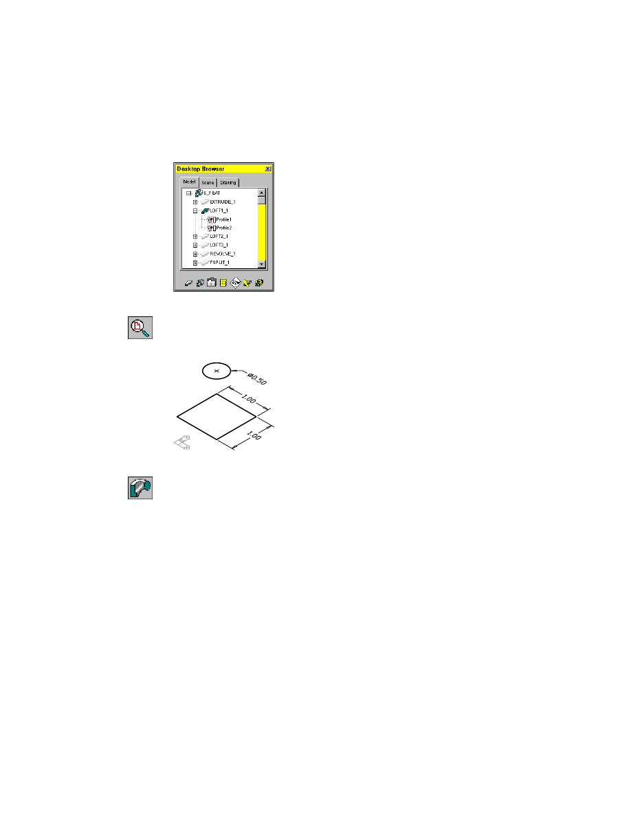
Expand LOFT1_1 in the Browser. Minimize EXTRUDE_1.
2
Zoom in to LOFT1_1.
Desktop Menu
View ➤ Zoom ➤ All
The LOFT1 part contains two planar sections you use to create a linear lofted
feature.
3
Create the loft feature, responding to the prompts.
Context Menu
In the graphics area, right-click and choose Sketched &
Work Features ➤ Loft.
Select profiles or planar faces to loft:
Specify the bottom profile
Select profiles or planar faces to loft:
Specify the top profile
Select profiles or planar faces to loft or [Redefine sections]:
Press
ENTER
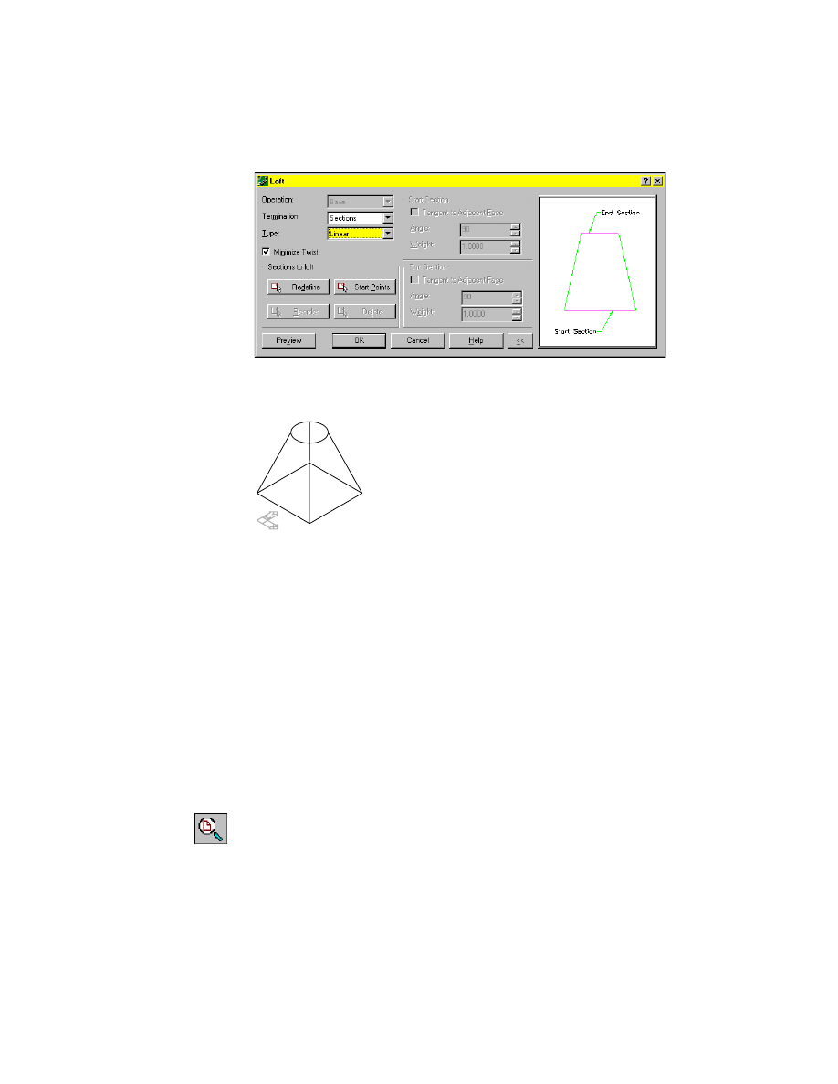
4
In the Loft dialog box, specify:
Type:
Linear
Creating Loft Features
|
145
5
Choose OK to exit the Loft dialog box.
Mechanical Desktop
®
calculates and displays the loft feature.
Save your file.
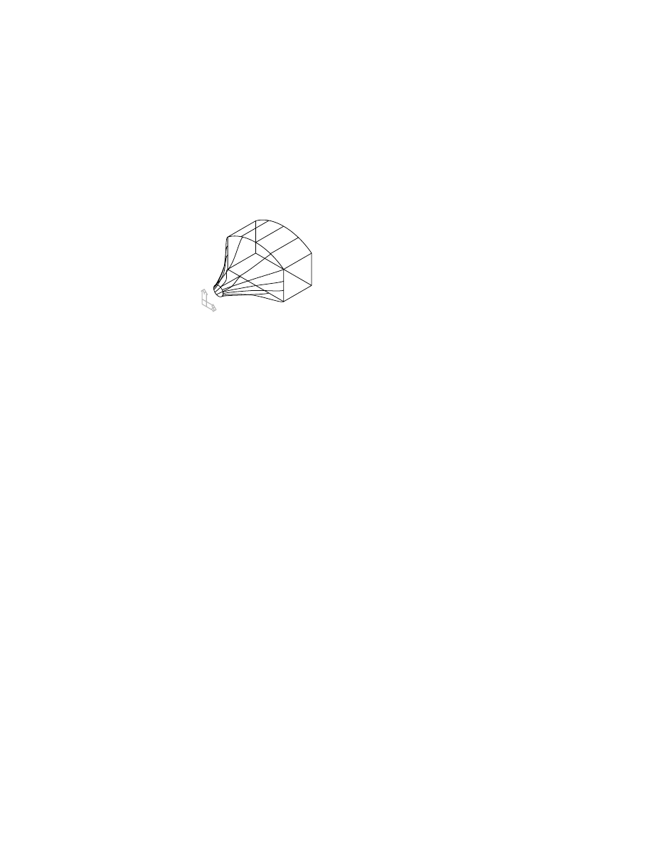
Next, you create a cubic loft blended through three planar sections.
Creating Cubic Lofts
A cubic loft is created by a gradual blend between two or more planar sec-
tions. Before the loft begins blending with the next section, you can control
the tangency and the take-off angle at the start and end sections, and the dis-
tance the loft follows the tangent or angle options.
To create a cubic loft
1
Make LOFT2_1 visible.
2
Activate LOFT2_1.
3
Make LOFT1_1 invisible.
4
Zoom in to LOFT2_1.
Browser
Right-click LOFT2_1, and choose Zoom to.
146
|
Chapter 8
Creating Sketched Features
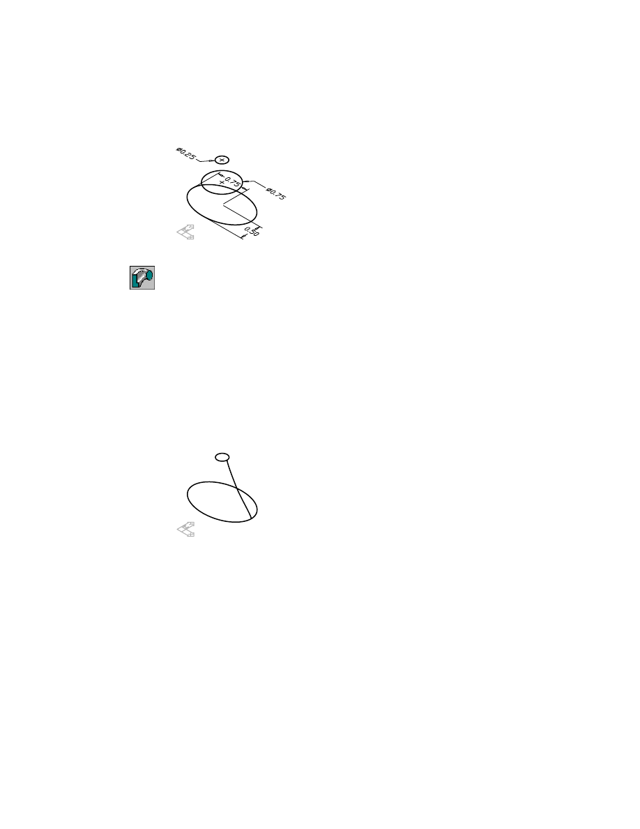
LOFT2 contains three profiles defining the sections you use for the loft feature.
5
Create the loft, responding to the prompts.
Context Menu
In the graphics area, right-click and choose Sketched &
Work Features ➤ Loft.
Select profiles or planar faces to loft:
Select the bottom profile
Select profiles or planar faces to loft:
Select the middle profile
Select profiles or planar faces to loft or [Redefine sections]:
Select the top profile
Select profiles or planar faces to loft or [Redefine sections]:
Press
ENTER
6
In the Loft dialog box specify:
Type:
Cubic
7
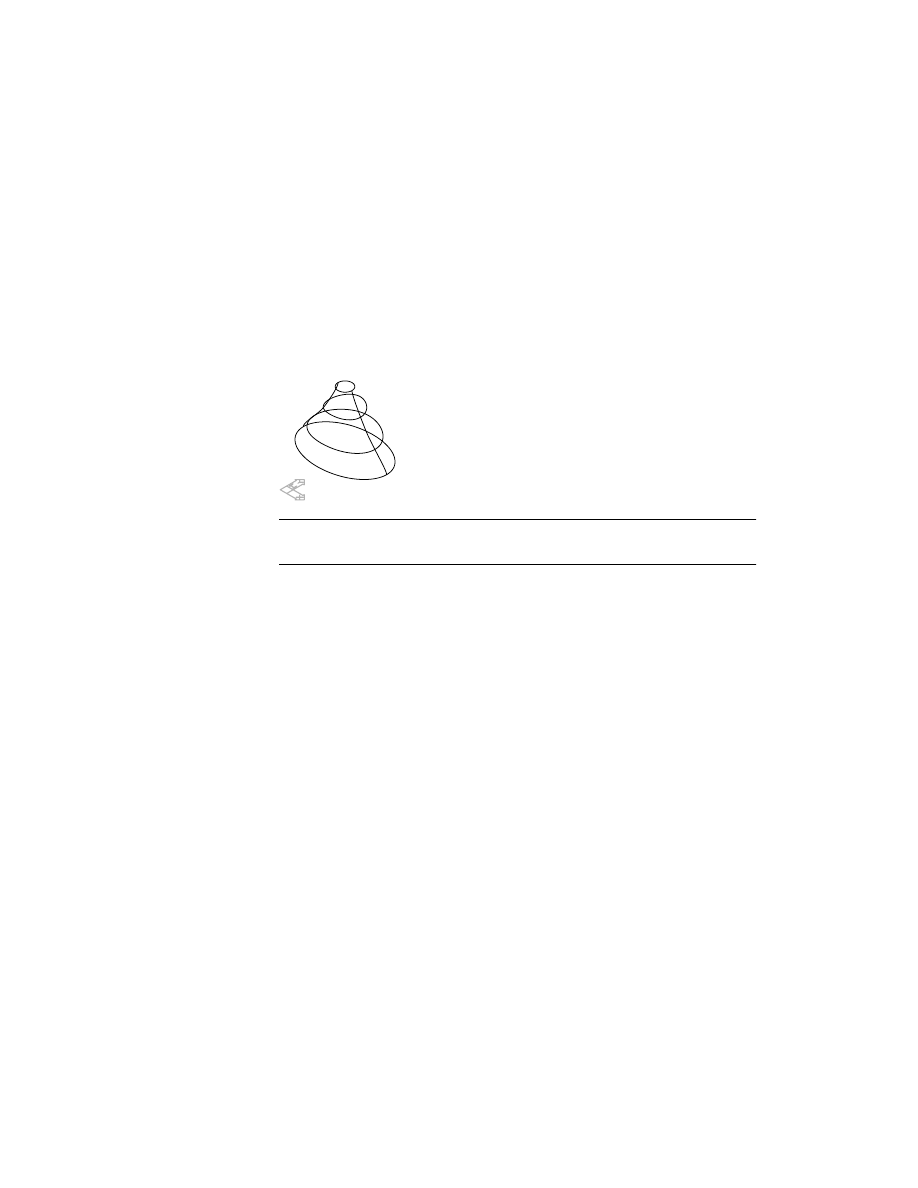
Choose OK to exit the Loft dialog box.
The loft is displayed with isolines because it is created from elliptical and cir-
cular sections. The default isoline setting displays the loft as in the following
illustration.
For a better view of the loft, increase the number of isolines defining the
feature.
Creating Loft Features
|
147
To change the number of isolines
1
Modify the
ISOLINES
system variable.
Command
ISOLINES
New value for ISOLINES <4>:
Enter 6
2
Regenerate your drawing.
Desktop Menu
View ➤ Regen
Mechanical Desktop regenerates the drawing and displays the loft using
more isolines.
NOTE
A higher value for
ISOLINES
increases the time it takes to recalculate a
part. In general, keep
ISOLINES
at its default value (4).
3
Reset the value of
ISOLINES
to its default setting.
Command
ISOLINES
New value for ISOLINES <6>:
Enter 4
4
Regenerate your drawing.
Desktop Menu
View ➤ Regen
Save your file.
In the next exercise you create a cubic loft using an existing part face as the
start section of the loft.
148
|
Chapter 8
Creating Sketched Features
To create a cubic loft from an existing face
1
Make LOFT3_1 visible.
2
Activate LOFT3_1
.
3
Make LOFT2_1 invisible.
4
Zoom in to LOFT3_1.
LOFT3 contains an existing extrusion and two profiles parametrically con-
strained to it.
NOTE
For clarity, the parametric dimensions are not shown.
5
Select the profiles to use for the cubic loft, following the prompts, and join
the loft to the existing extrusion.
Context Menu
In the graphics area, right-click and choose Sketched &
Work Features ➤ Loft.
Select profiles or planar faces to loft:
Select the front planar face (1)
Enter an option [Accept/Next] <Accept>:
Highlight the front face and press
ENTER
Select profiles or planar faces to loft:
Select the first profile (2)
Select profiles or planar faces to loft or [Redefine sections]:
Select the second profile (3)
Select profiles or planar faces to loft or [Redefine sections]:
Press
ENTER
1
2
3
Editing Loft Features
|
149
6
In the Loft dialog box, specify:
Operation:
Join
Type:
Cubic
Choose OK to exit the Loft dialog box.
Your drawing should look like this.
Save your file.
Editing Loft Features
You edit loft features the same way extruded features are edited—change the
profiles or modify the loft feature itself.
Try editing the loft features you created in this section.
150
|
Chapter 8
Creating Sketched Features
Creating Revolved Features
You create revolved features by revolving a closed profile about an axis. The
axis may be a work axis or a part edge.
To create a revolved feature about a work axis
1
Make REVOLVE_1 visible.
2
Activate REVOLVE_1.
3
Expand REVOLVE_1 and make Work Axis1 visible.
4
Make LOFT3_1 invisible.
5
Zoom in to REVOLVE_1.
REVOLVE_1 contains a profile parametrically constrained to a work axis.
NOTE
For clarity, the parametric dimensions are not shown.
6
Create a revolved feature.
Context Menu
In the graphics area, right-click and choose Sketched &
Work Features ➤ Revolve.
7
Respond to the prompt as follows:
Select revolution axis:
Specify the work axis
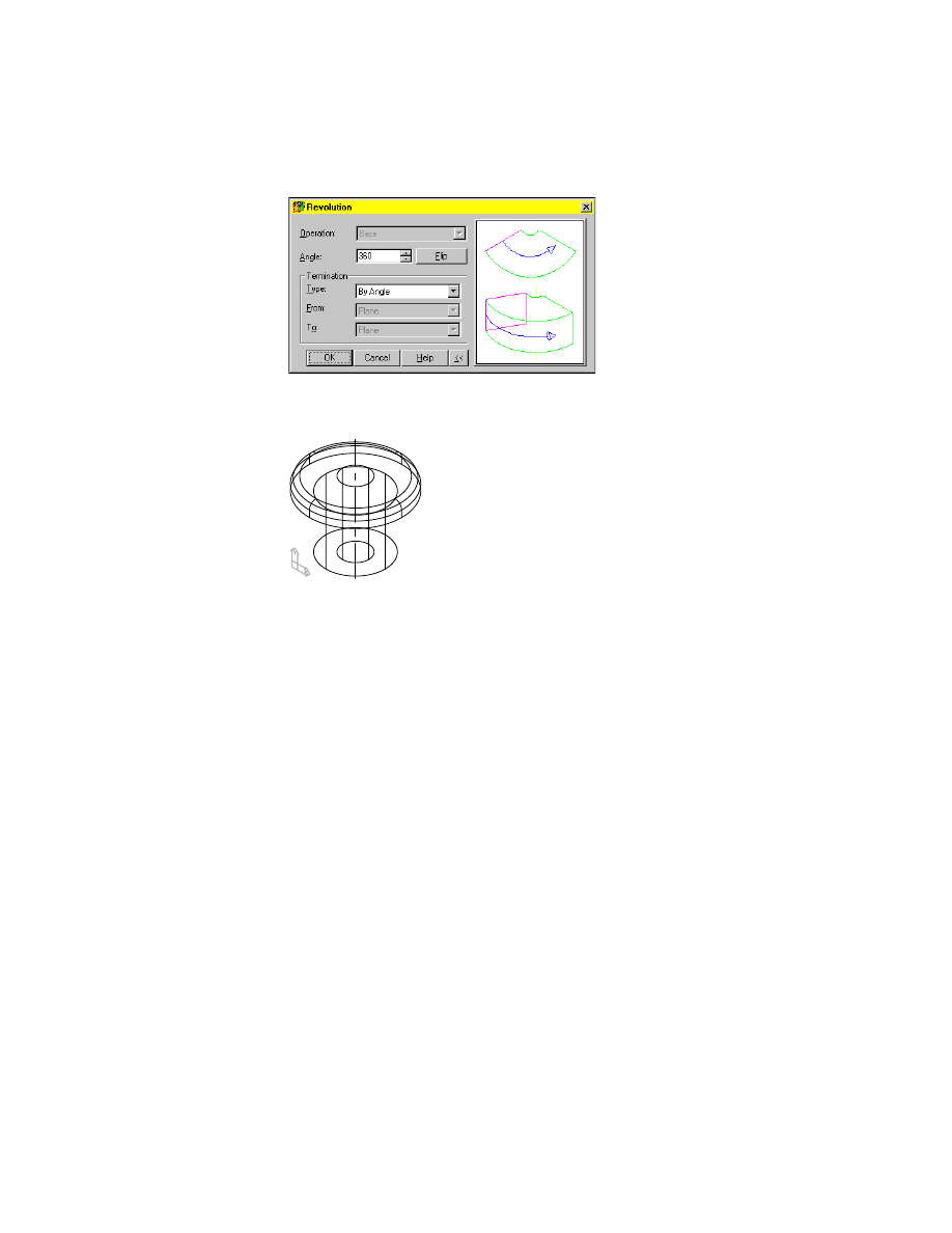
8
In the Revolution dialog box, specify:
Angle:
Enter 360
Termination:
By Angle
work axis
Editing Revolved Features
|
151
Choose OK.
Mechanical Desktop calculates and displays the feature.
Save your file.
Editing Revolved Features
Edit a revolved feature by making changes to the profile, or by modifying the
feature itself (like editing extruded and lofted features).
Try editing your revolved feature following the procedures for editing
extruded features you learned earlier in this tutorial.
152
|
Chapter 8
Creating Sketched Features
Creating Face Splits
Use face splits to split existing part faces. They can be created with
■
An existing part face
■
A work plane
■
A split line
First, use one of the part’s existing faces to split a face.
To split a face using an existing part face
1
Make FSPLIT_1 visible.
2
Activate FSPLIT_1.
3
Make REVOLVE_1 invisible.
4
Zoom in to FSPLIT_1.
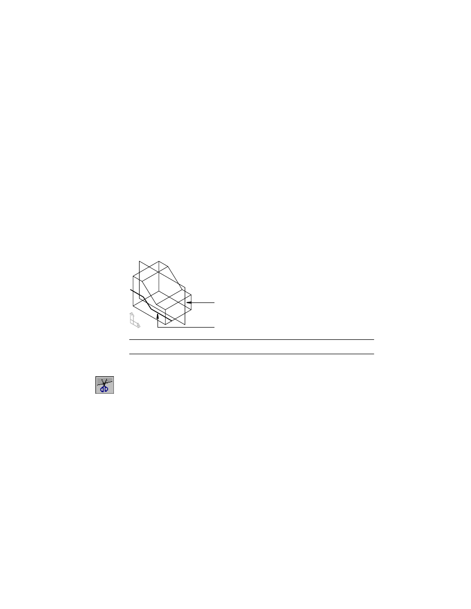
FSPLIT_1 contains a part, a work plane, and a split line.
NOTE
For clarity, the parametric dimensions are not shown.
5
Create the face split, responding to the prompts.
Context Menu
In the graphics area, right-click and choose Sketched &
Work Features ➤ Face Split.
Enter facesplit type [Planar/pRoject] <pRoject>:
Enter p
Select faces to split or [All]:
Specify the left back face (1)
Enter an option [Accept/Next] <Accept>:
Enter n to flip to the back face or press
ENTER
to continue
Select faces to split or [All/Remove]:
Press
ENTER
Select planar face or work plane for split:
Specify the top right face (2)
Enter an option [Accept/Next] <Accept>:
Enter n to flip to the top face or press
ENTER
work plane
split line
Creating Face Splits
|
153
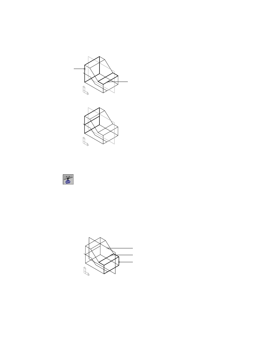
Mechanical Desktop splits the back face into two faces.
Next, split a face using a work plane.
To split a face using a work plane
1
Create the face split, responding to the prompts.
Context Menu
In the graphics area, right-click and choose Sketched &
Work Features ➤ Face Split.
Enter facesplit type [Planar/pRoject] <pRoject>:
Enter p
Select faces to split or [All]:
Specify the top right face (1)
Enter an option [Accept/Next] <Accept>:
Enter n to flip to the top face or press
ENTER
to continue
Select faces to split or [All/Remove]:
Specify the right front face (2)
Enter an option [Accept/Next] <Accept>:
Enter n to flip to the front face or press
ENTER
to continue
Select faces to split [All/Remove]:
Press
ENTER
Select planar face or work plane for split:
Specify the work plane (3)
1
2
3
1
2
154
|
Chapter 8
Creating Sketched Features
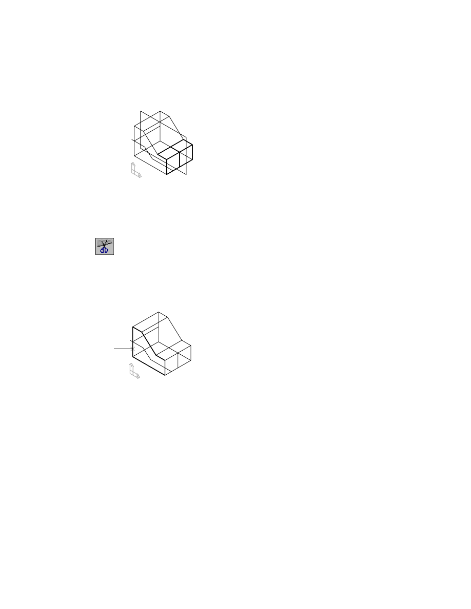
Your drawing should look like this.
Now split the front face using the split line sketch.
To split a face using a split line
1
Make Work Plane2 invisible.
2
Create the face split, responding to the prompts.
Context Menu
In the graphics area, right-click and choose Sketched &
Work Features ➤ Face Split.
Enter facesplit type [Planar/pRoject] <pRoject>:
Press
ENTER
Select faces to split or [All]:
Specify the left front face (1)
Enter an option [Accept/Next] <Accept>:
Enter n to flip to the front face or press
ENTER
to continue
Select faces to split or [All/Remove]:
Press
ENTER
If you use the Browser method, the prompts are not displayed.
1
Editing Face Splits
|
155
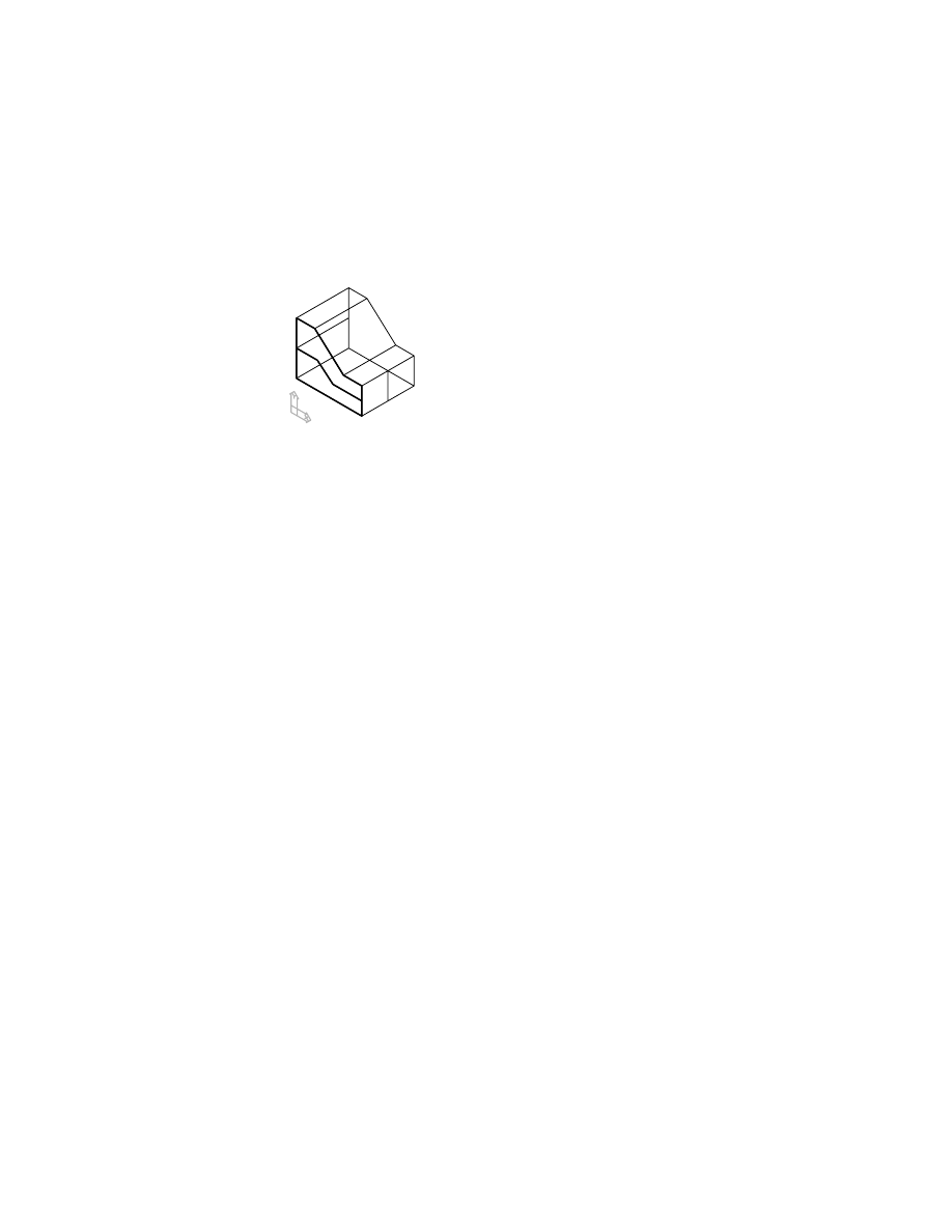
When you choose the Project option, Mechanical Desktop automatically
looks for an unconsumed split line. If more than one split line exists, you are
prompted to select the split line for the face split.
Mechanical Desktop displays the new face split.
The Browser contains three face split features.
Save your file.
Editing Face Splits
Face splits created from an existing planar face can be edited by modifying
the position of the face on the part. Face splits created from a work plane can
be edited by modifying the dimensions controlling the location of the work
plane. Face splits created from a split line can be modified by editing the
parametric dimensions that control the split line.
Try editing the face splits you just completed in this exercise.
Creating Sweep Features
Sweep features can be either 2D or 3D. Both are created by sweeping a closed
profile along a path.
156
|
Chapter 8
Creating Sketched Features
Creating 2D Sweep Features
You create a 2D sweep feature by sweeping a profile along a path that lies on
a 2D plane. The feature may be the base feature of your part, or you can use
Boolean operations to cut, intersect, split, or join the feature to your part.
To create a 2D sweep
1
Make SWEEP1_1 visible.
2
Activate SWEEP1_1.
3
Make FSPLIT_1 invisible.
4
Zoom in to SWEEP1_1.
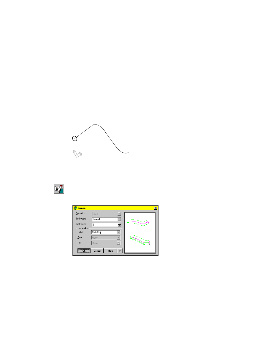
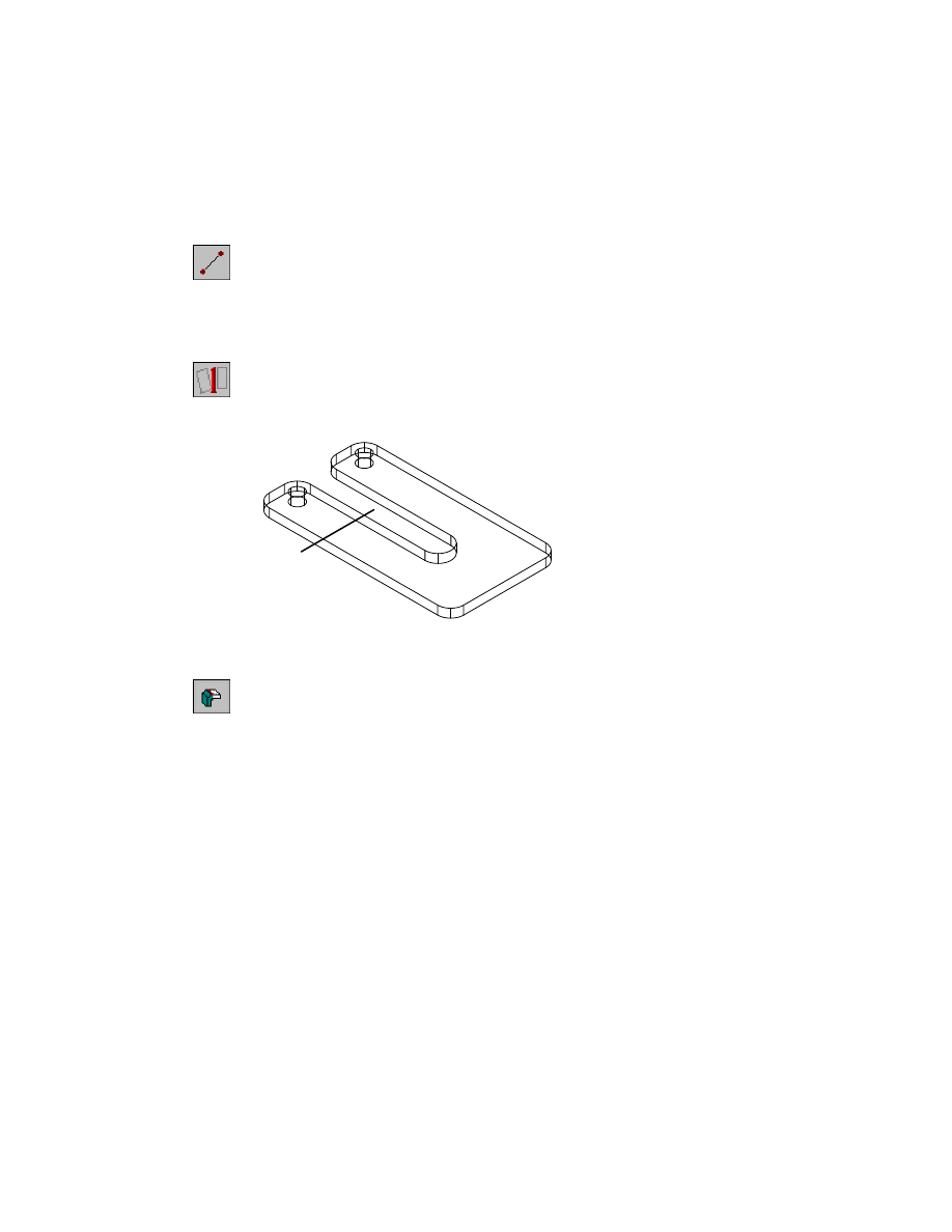
SWEEP1_1 contains a solved profile constrained to the start of a 2D path.
NOTE
For clarity, the parametric dimensions and the work point are not shown.
5
Create the 2D sweep.
Context Menu
In the graphics area, right-click and choose Sketched &
Work Features ➤ Sweep.
6
In the Sweep dialog box, choose OK to accept the settings.
Creating Sweep Features
|
157
Your drawing should look like this.
NOTE
Increase the value of
ISOLINES
for a more accurate display of the sweep.
Save your file.
Creating 3D Sweep Features
With Mechanical Desktop, you can also sweep profiles along a variety of 3D
paths. Use these paths to create a feature swept along
■
A helical path
■
A spiral path
■
A path defined by a 3D spline
■
A path created from filleted 3D polylines and lines
■
A path created from existing part edges
For more information about creating 3D paths, see chapter 6, “Creating Para-
metric Sketches.”
First, create a 3D helical sweep.
To create a 3D helical sweep
1
Make SWEEP2_1 visible.
2
Activate SWEEP2_1.
3
Make SWEEP1_1 invisible.
4
Zoom in to SWEEP2_1.
158
|
Chapter 8
Creating Sketched Features
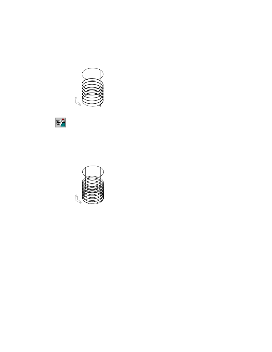
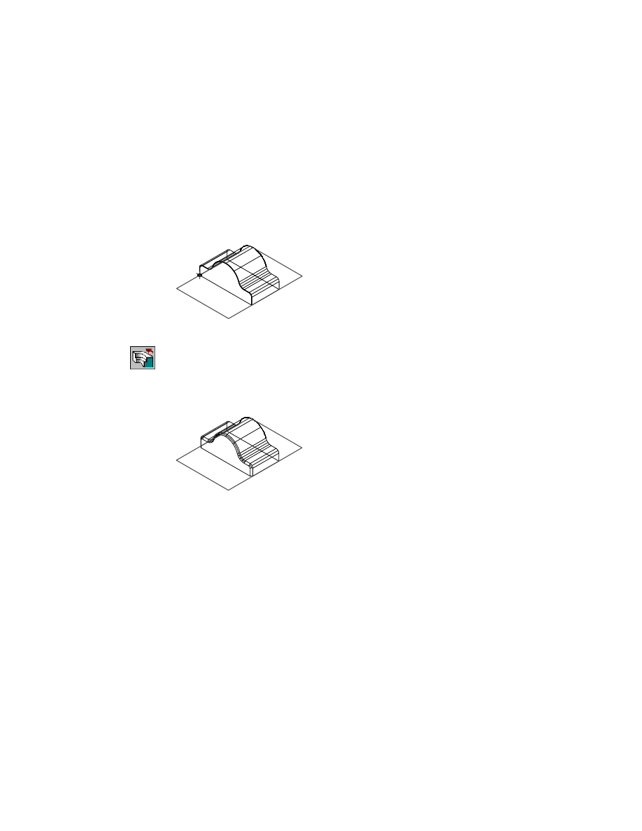
SWEEP2_1 contains a cylinder and a helical path. A solved profile is constrained
to the start of the path.
5
Create the 3D helical sweep.
Context Menu
In the graphics area, right-click and choose Sketched &
Work Features ➤ Sweep.
6
In the Sweep Feature dialog box, choose OK to accept the settings.
You can create a cut, join, intersection, or split feature. These options are
available because there is a base feature in the part definition.
Choose OK to exit the dialog box.
Mechanical Desktop calculates the sweep and displays your part.
Save your file.
Next, create a spiral 3D sweep.
Creating Sweep Features
|
159
To create a spiral 3D sweep
1
Make SWEEP3_1 visible.
2
Activate SWEEP3_1.
3
Make SWEEP2_1 invisible.
4
Zoom in to SWEEP3_1.
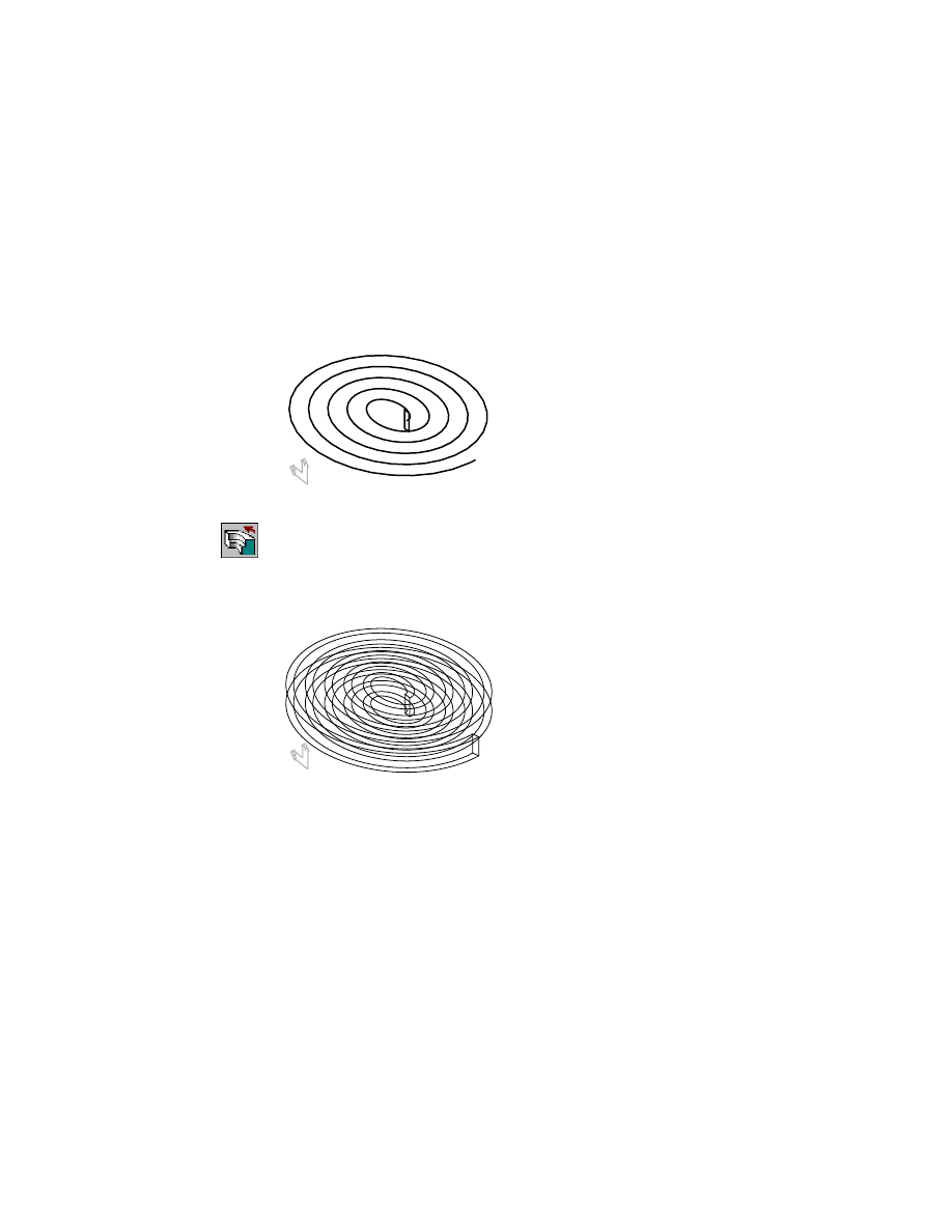
SWEEP3_1 contains a spiral helical path and a solved profile constrained to
the start of the path. The spiral path is elliptical.
5
Create the 3D sweep.
Context Menu
In the graphics area, right-click and choose Sketched &
Work Features ➤ Sweep.
6
In the Sweep Feature dialog box, choose OK to accept the settings.
Your drawing should look like this.
Save your file.
Next, create a sweep using a 3D edge path.
160
|
Chapter 8
Creating Sketched Features
To create a sweep from a 3D edge path
1
Make SWEEP4_1 visible.
2
Activate SWEEP4_1.
3
Make SWEEP3_1 invisible.
4
Zoom in to SWEEP4_1.
SWEEP4_1 contains a 3D edge path and a solved profile constrained to the
start of the path.
5
Create the sweep.
Context Menu
In the graphics area, right-click and choose Sketched &
Work Features ➤ Sweep.
6
In the Sweep Feature dialog box, choose OK to accept the settings.
Your drawing should look like this.
Save your file.
Next, sweep a feature along a path created from non-planar lines and arcs.
Creating Sweep Features
|
161
To create a sweep from a 3D pipe path
1
Make SWEEP5_1 visible.
2
Activate SWEEP5_1.
3
Make SWEEP4_1 invisible.
4
Zoom in to SWEEP5_1.
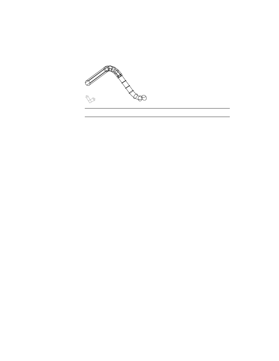
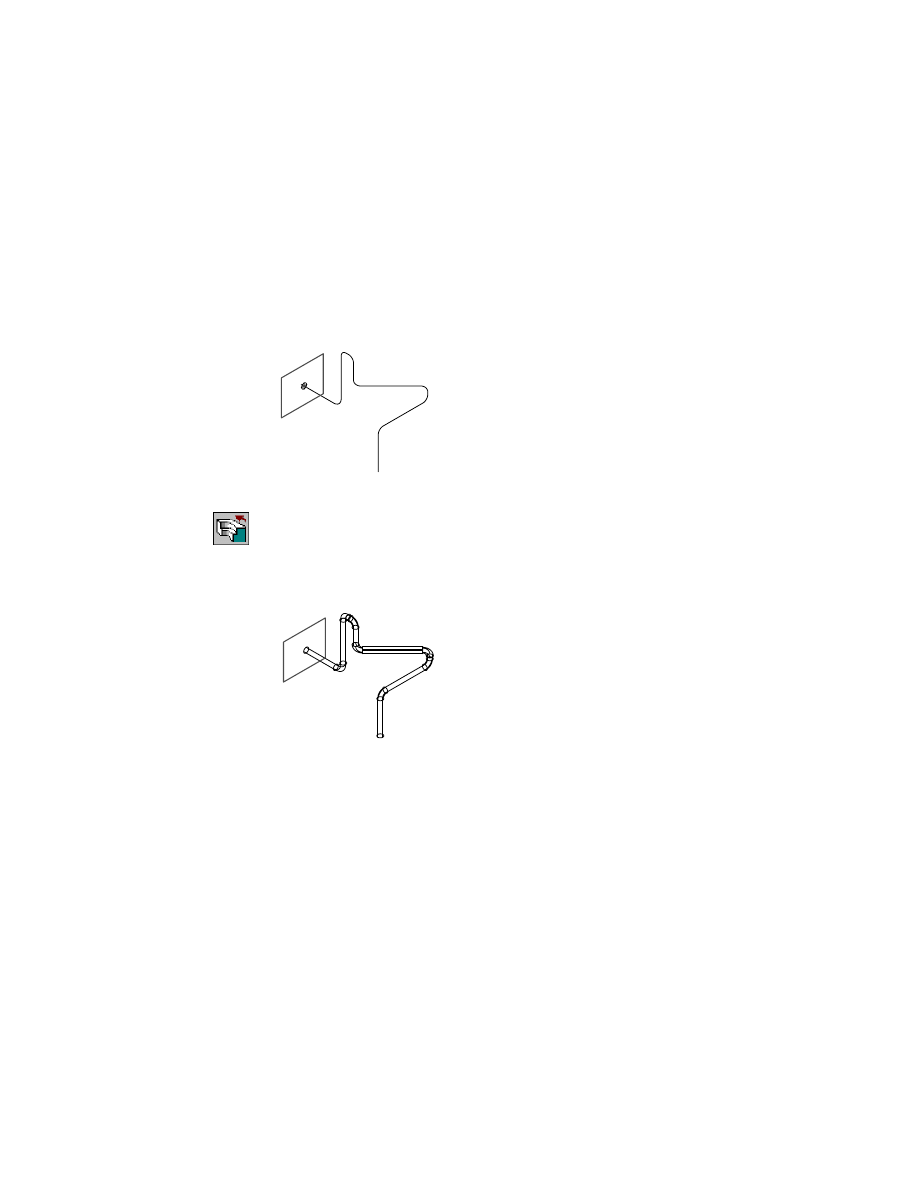
SWEEP5_1 contains a 3D pipe path and a solved profile constrained to the
start of the path.
5
Create the sweep.
Context Menu
In the graphics area, right-click and choose Sketched &
Work Features ➤ Sweep.
6
In the Sweep dialog box, choose OK to accept the settings.
Your drawing should look like this.
Save your file.
Finally, create a swept feature using a path created from a 3D spline.
162
|
Chapter 8
Creating Sketched Features
To create a sweep from a 3D spline path
1
Make SWEEP6_1 visible.
2
Activate SWEEP6_1.
3
Make SWEEP5_1 invisible.
4
Zoom in to SWEEP6_1.
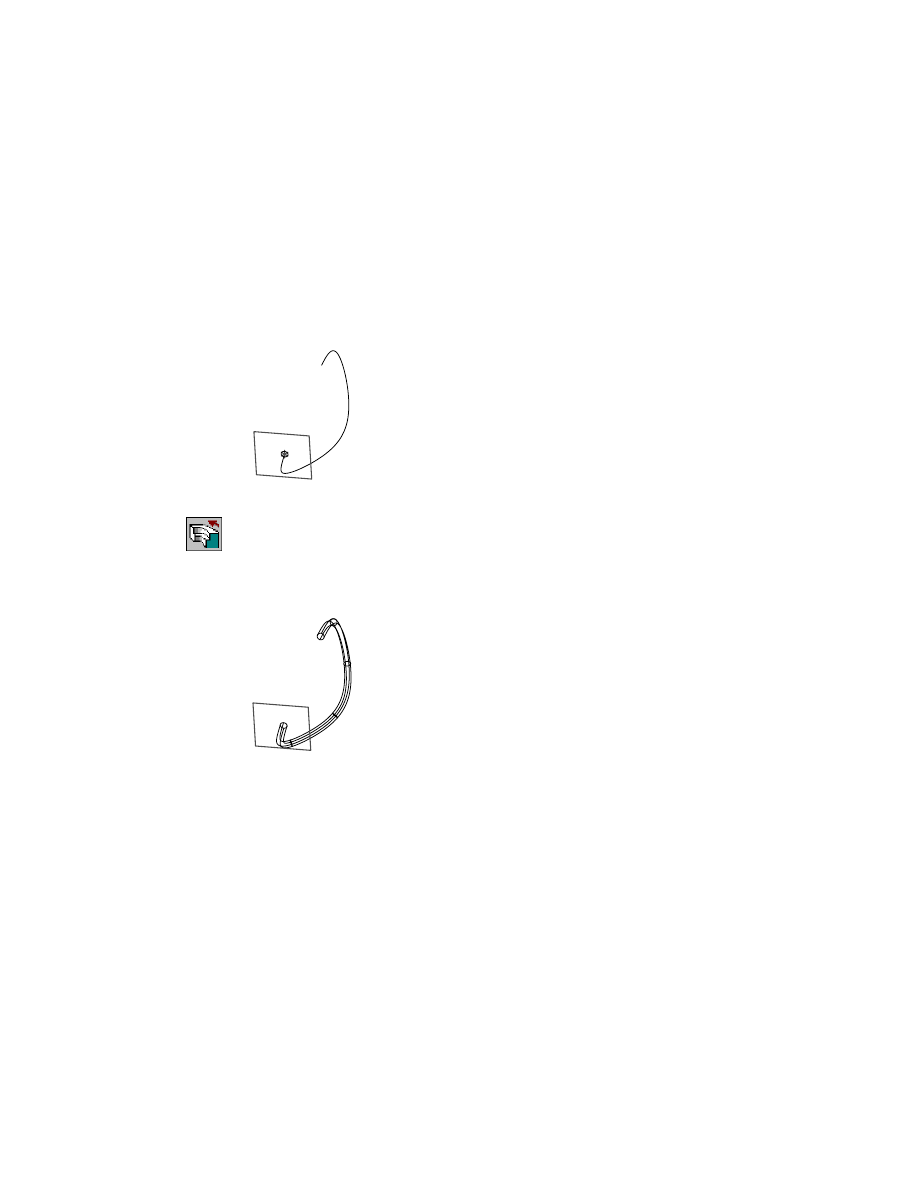
SWEEP6_1 contains a 3D spline path and a solved profile constrained to the
start of the path.
5
Create the sweep.
Context Menu
In the graphics area, right-click and choose Sketched &
Work Features ➤ Sweep.
6
In the Sweep Feature dialog box, choose OK to accept the settings.
Your drawing should look like this.
Save your file.

Editing Sweep Features
|
163
Editing Sweep Features
As with all sketched features, sweep features can be edited by modifying the
profile, the path, or the feature itself.
Try modifying the sweep features you just created.
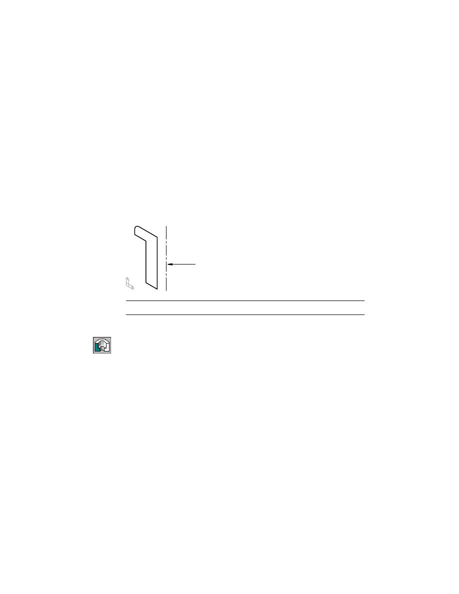
Creating Bend Features
The bend feature is for bending flat or cylindrical parts.
To create a bend feature, you sketch a single line segment on your part and
create an open profile to define the tangency location where the part transi-
tions from its current shape to the final bent shape.
To bend an entire flat part, sketch the open profile to extend over the entire
part. To bend only a portion of a flat part, sketch the open profile over only
the portion you want to bend.
By choosing options and entering values in the Bend dialog box, you design
a theoretical cylinder tangent to the open profile, about which the part
bends. The bend feature is placed automatically in one operation.
In the next exercise, you create a bend feature on a portion of a flat part.
Make the BEND_1 part visible. Then activate it and use
ZOOM
to position the
part on your screen.
164
|
Chapter 8
Creating Sketched Features
To create a bend feature on a flat part
1
Use
LINE
to sketch a line on one side of the plate, responding to the prompts.
Context Menu
In the graphics area, right click and choose 2D Sketching ➤
Line.
Specify first point:
Select the start point of the line
Specify next point [or Undo]:
Select the end point of the line, and press
ENTER
2
Use
AMPROFILE
to create an open profile, responding to the prompt.
Context Menu
In the graphics area, right-click and choose Sketch Solving
➤ Single Profile.
Select part edge to close the profile <open profile>:
Press
ENTER
In the Browser, an icon for the open profile is displayed.
3
Use
AMBEND
to create the bend feature.
Context Menu
In the graphics area, right-click and choose Sketched
Work Features ➤ Bend.
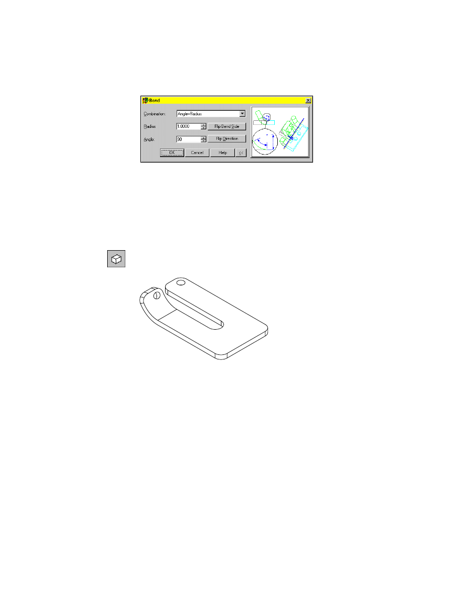
4
In the Bend dialog box specify:
Combination:
Angle+Radius
Radius:
1.0
Angle:
90
Flip Bend Side:
Verify that the direction arrow points toward the hole
Flip Direction:
Verify that the arrow points up
Editing Bend Features
|
165
Choose OK.
Hide the hidden lines to see your part better. To display silhouette edges, you
set the
DISPSILH
system variable to 1 first.
5
Change the setting for
DISPSILH
.
Command
DISPSILH
New value for DISPSILH <0>:
Enter 1
6
Use HIDE to hide the hidden lines.
Desktop Menu
View ➤ Hide
Your part should look like this.
The bend is completed, and an icon for the bend feature is displayed in the
Browser. Save your file.
Editing Bend Features
Use typical editing methods to edit a profile for a bend feature or to redefine
the bend.
Try redefining the bend feature you just created.

166
Wyszukiwarka
Podobne podstrony:
ch8 (2)
pm ch8
Atari 8 Bit Demopac 7 Some Special Features
features
E in T features & nescessity
CH8 (3)
Ch8 FrameworkForConventionalForestrySystemsForSustainableProductionOfBioenergyANDIndex
CH8 (4)
CE Specific features
L9 Sketch Based?atures I ok
Ch8 Q5
ch8 pl
2015 Styk Ada 2rok AW sketching
Ch7 Constrain Sketches
N Feature Neural Network Human Face Recognition
Ch8 Q3
Audiovisual translation of feature films eng lithuanian
ch8
więcej podobnych podstron