www.ednmag.com
May 25, 2000 | edn
101
THE ELLIPTIC FILTER IS THE BEST CHOICE FOR MEETING
STRINGENT MAGNITUDE-RESPONSE REQUIREMENTS, AND
A DESIGN TECHNIQUE HELPS YOU TO MAXIMIZE THE BAND-
EDGE SELECTIVITY WITHOUT INCREASING FILTER ORDER.
E
lectronic-filter design, whether analog,
digital, or distributed, is an essential part of
many electrical engineers’ workdays. Frequen-
cy-selective networks are useful for suppressing
noise, rejecting unwanted signals, or in some way
manipulating the input signal’s characteristics. Al-
though applications abound, engineers typically use
classical filters that are polynomial approximations
to the brick-wall filter (see sidebar “A new look at
the brick-wall filter”). These classical filters include
Butterworth, Chebyshev, and elliptic filters.
Filter requirements often call for highly selective
filters, especially in bandpass filters designed to re-
ject out-of-band carriers. If the cutoff-rate specifi-
cation is stringent, the classical Butterworth and
Chebyshev filters result in high orders. A higher or-
der adds complexity to the filter, and the resulting
design is more difficult to tune. The sensitivity of the
filter to its components also increases. These
issues apply to both lumped-element real-
izations and microwave structures. For microwave
structures, the physical features of the implementa-
tion directly influence the overall characteristics of
the filter.
When selectivity is an issue, you can rely on ellip-
tic filters, which provide the lowest order imple-
mentation of the classical filters for the same fre-
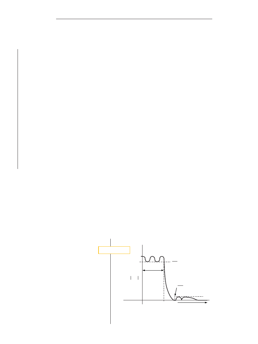
quency and rejection requirements. Elliptic filters are
equiripple in the passband and the stopband (Fig-
ure 1). The finite zeros of transmission, which al-
low the filter to have a narrower transition band, de-
termine the ripple response in the stopband. The
price of a narrower transition band is asymptotic
roll-offs of
220 (order n odd) or 240 (order n even)
dB/decade (Reference 1) and the additional com-
plexity of achieving the transmission zeros.
Despite these limitations, the elliptic filter is the
filter of choice for stringent magnitude-response re-
quirements. The elliptic filter has the additional ad-
vantage of providing several degrees of freedom for
controlling its response, including band-edge selec-
tivity. Many designers resort to ad hoc and often
wasteful techniques to obtain superior selectivity.
However, a new technique allows you to maximize
the band-edge selectivity (BES) of elliptic filters
without increasing filter order. The technique effec-
tively narrows the transition band by moving the
notch frequency closer to the passband. This change
increases the lobe levels to the original stopband-
rejection requirement and impacts delay perform-
Designing elliptic filters with
maximum selectivity
K
K
1+
e
2
1
K
1+
e
2
2
PASSBAND
v=1
STOPBAND
H(j
v)
2
The magnitude response of an elliptic filter shows equal rip-
ple in the passband and stopband.
F i g u r e 1
designfeature
By Celestino A Corral, Motorola Inc
designfeature
Elliptic-filter design
102
edn | May 25, 2000
www.ednmag.com
ance in the passband. A design example
shows the ease with which you can design
elliptic filters with maximum selectivity
without increasing filter order. By maxi-
mizing the selectivity without increasing
the filter order, you can reject more noise
or unwanted signal components closer to
the band edge—a desirable function.
MAKE BETTER FILTERS WITH NO ADDED COST
You can use a recently derived formu-
lation for the band-edge selectivity of el-
liptic filters and use a method for maxi-
mizing selectivity without increasing the
filter order (Reference 2). This useful
method, in conjunction with the sensi-
tivity calculations, can result in superior
filters at no additional cost. The follow-
ing design example highlights the power
and ease of this method.
The BES of a filter is:
The selectivity is the slope of the mag-
nitude response of the filter at the nor-
malized corner frequency, or band edge.
Selectivity is a measure of the cutoff rate,
and the “larger-the-better” characteristic
applies here. Most designers generally ac-
cept selectivity as a property of a filter
and not as a goal of filter design. How-
ever, you can treat filter selectivity as a de-
sign parameter that you can optimize.
The BES of an elliptic filter is (Refer-
ence 2)
where n is the order,
e
1
is the passband
ripple parameter, and
V
S
is the stopband corner frequency, and
e
2
is the stopband ripple parameter (Fig-
ure 1). If you’re familiar with filter theo-
ry, you’ll recognize the first term in the
parentheses of Equation 2 as the BES of
the Chebyshev filter. However, for the el-
liptic filter, the new term (1
2m
()/(12m)
scales this selectivity. As m
(0, Equation
2 reduces to
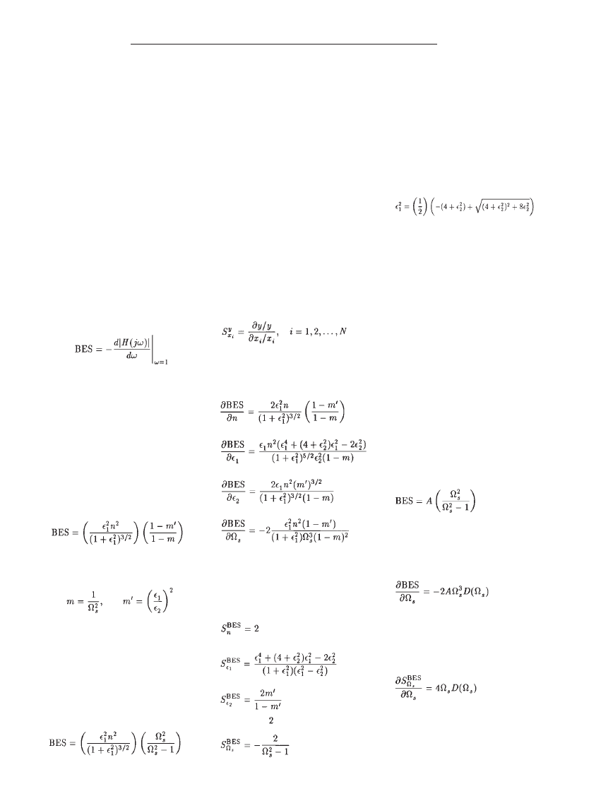
The result of Equation 4 is that the
BES of an elliptic filter is greater than that
of the Chebyshev filter for any
V
S
.1, giv-
en the same order and passband ripple.
Figure 2 shows a plot of the scaling fac-
tor. If the passband and stopband ripple
are fixed, then
V
S
is the only degree of
freedom for maximizing the BES without
increasing the filter order n.
REVIEW FILTER SENSITIVITIES
Before describing the filter-maximiza-
tion process, it is useful to review the sen-
sitivities of the BES of the elliptic filter
to the various filter parameters. Recall
that, when a dependent variable, y, is a
function of two or more independent
variables, x
i
, where i
51,2,...N, the sensi-
tivity of y with respect to x
i
is as follows
(Reference 3):
You therefore need to calculate the
partial derivatives of the BES with respect
to the various filter parameters as follows:
These equations are fairly complicat-
ed. However, by calculating the sensitiv-
ity using Equation 5 you get simplified
results (Reference 2):
In most applications, the filter order is
fixed, and Equation 10 always holds. On
the other hand, you can control the sen-
sitivity of the BES with respect to the
passband ripple parameter
e
1
using either
e
1
or
e
2
. By setting
l5e
1
2
, the numerator
of Equation 11 becomes a quadratic of
the form
l
2
1(41e
2
2
)
l22e
2
2
50. Solving
for
l, you obtain
Equation 14 strictly depends on
e
2
.
Therefore, minimizing the sensitivity is
possible by setting
e
1
as in Equation 14.
You can reduce the sensitivity of the
BES with respect to the stopband rejec-
tion
e
2
by making
e
2
..e
1
for any value
of
e
1
. Alternatively, you can reduce this
sensitivity by making
e
1
small. This in-
teraction of parameters is unique to el-
liptic filters.
Note from Equation 13 that the sen-
sitivity of the stopband corner frequency
V
S
increases as you decrease
V
S
. Howev-
er, decreasing
V
S
increases the BES. Thus,
although you can increase BES by reduc-
ing
V
S
, you must temper your intent by
the resulting increase in sensitivity. Con-
sider the effective change in the BES
along with the change in the associated
sensitivity. Again, using the assumption
that m’ 0, you can rewrite Equation 4 as:
Taking the derivative of Equation 15
with respect to
V
S
gives the rate of change
of the BES with respect to the parameter
you are modifying for the maximization:
where D(
V
S
)
51/(V
S
2
21) is the stop-
band-frequency factor. As for the sensi-
tivity of Equation 13, you can easily cal-
culate
Because
V
S
>1 and
V
S
3
>
V
S
, you can
improve the BES of the filter at a greater
rate than you degrade the corresponding
sensitivity (Reference 4).
(1)
(2)
(3)
(5)
(15)
(16)
(17)
(14)
(4)
(6)
(7)
(8)
(9)
(10)
(11)
(12)
(13)
.
,
.
.
.
;
;
;
and
.
;
;
;
and
.
.
.
,
.
designfeature
Elliptic-filter design
104
edn | May 25, 2000
www.ednmag.com
Maximizing the filter involves solving
for the incremental order of the
elliptic filter. You can obtain the
order of an elliptic filter from a filter
nomograph (Reference 1) or calculate
the order using the following equation
(Reference 5).
In Equation 18, K is the complete el-
liptic integral of the first kind (Reference
6) as follows:
You can find tabulated results of the
above integral in mathematical hand-
books or easily calculate the results using
software packages such as MathCAD
(Mathsoft Inc, Cambridge, MA).
The result of Equation 18 is a real
number, and you select the next
highest integer, that is
where the subscript i denotes an integer.
You can always select a higher order to
satisfy an arbitrary selectivity require-
ment, but it is useful to maximize the se-
lectivity with no increase in order. As al-
ready noted,
e
1
and
e
2
are fixed for most
practical cases, and m’ 0. Thus, the pa-
rameter
V
S
is the degree of freedom for
maximizing the selectivity of the filter
while assuring that ni remains fixed.
You now need to make a distinction
between
~
V
S
, which is the variable, and
V
S
,
which is the value of the specified stop-
band corner frequency. Because
~
V
S
is the
variable, you can write Equation 20 as
where C is a constant and
~
m
51/
~
V
S
2
, such
that
where n is the real number from the
equality in Equation 18. Normalizing
Equation 22 using K(m)/K(1
2m) pro-
duces the result
Because you must make
~
V
S
,V
S
to in-
crease the selectivity, make
Substituting Equation 24 into Equa-
tion 23 yields
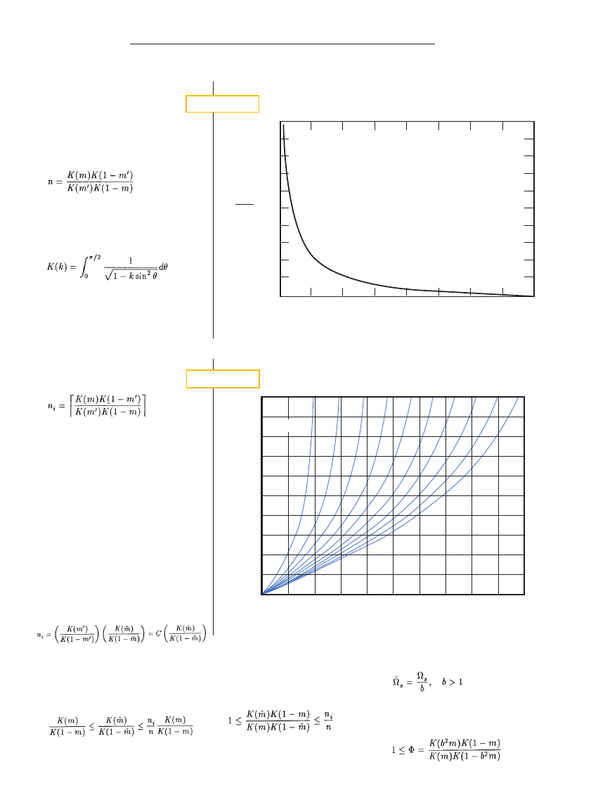
For a given V
S
curve and value of
F
F
, you can calculate
~
V
V
S
5
5V
V
S
/b.
2
1.9
1.8
1.7
1.6
1.5
1.4
1.3
1.2
1.1
1
1.1
1.2
1.3
1.4
1.5
1.6
1.7
1.8
1.9
2
1
F
b
V
S
=1.1
V
S
=2.0
F i g u r e 3
A scaling factor determines the band-edge selectivity of an elliptic filter.
V
S
V
2
S
V
2
S
21
20
18
16
14
12
10
8
6
4
2
1
1.5
2.5
3.5
4.5
2
3
4
5
0
(dB)
F i g u r e 2
(18)
(19)
(20)
(21)
(22)
(23)
(24)
(25)
.
.
,
,
,
.
.
.
designfeature
Elliptic-filter design
106
edn | May 25, 2000
www.ednmag.com
This equation has the same form as the
calculation of the filter order in
Equation 18. Thus, you can use
the same formulation and substitute the
appropriate values. Figure 3 shows a plot
of
F versus b for various values of V
S
. To
use this plot, follow four steps:
1. Calculate n from Equation 18 and n
i
from Equation 21.
2. Set
F
max
5n
i
/n to set the “excess or-
der.”
3. For the given
V
S
curve, read b from
the point where
V
S
5F
max
5n
i
/n.
4. Calculate
~
V
S
5V
S
/b.
This process results in the minimum
stopband corner frequency
~
V
S
that max-
imizes the BES for the given filter order.
All other parameters remain fixed.
This technique can be useful with fil-
ter-design packages. Filter-design pack-
ages typically provide designs that meet
the specifications but do not necessarily
maximize the selectivity of the filter. A
little extra work using the proposed
technique results in a superior filter with
no additional complexity. To use this
technique with the filter software, you
simply substitute the value
~
V
S
for the
original
V
S
requirement for maximum
selectivity.
DESIGN EXAMPLE DEMONSTRATES TECHNIQUE
To demonstrate the effectiveness of
the technique, consider the following
lowpass-filter requirements: passband
ripple M
P
51.25 dB, stopband rejection
M
S
540 dB, passband frequency f
P
51000
Hz, and stopband frequency f
S
52000
Hz. From filter nomographs, you can
quickly determine that this set of re-
quirements would result in an eighth-or-
der Butterworth or a fifth-order Cheby-
shev filter.
From M
P
51.25 dB, e
1
50.5775. From
M
S
540 dB, e
2
5100. From the frequency
requirement,
V
S
5f
S
/f
P
52. Using Equa-
tion 18, you can calculate the order
n
53.25482. Select the next highest order,
so ni
54.
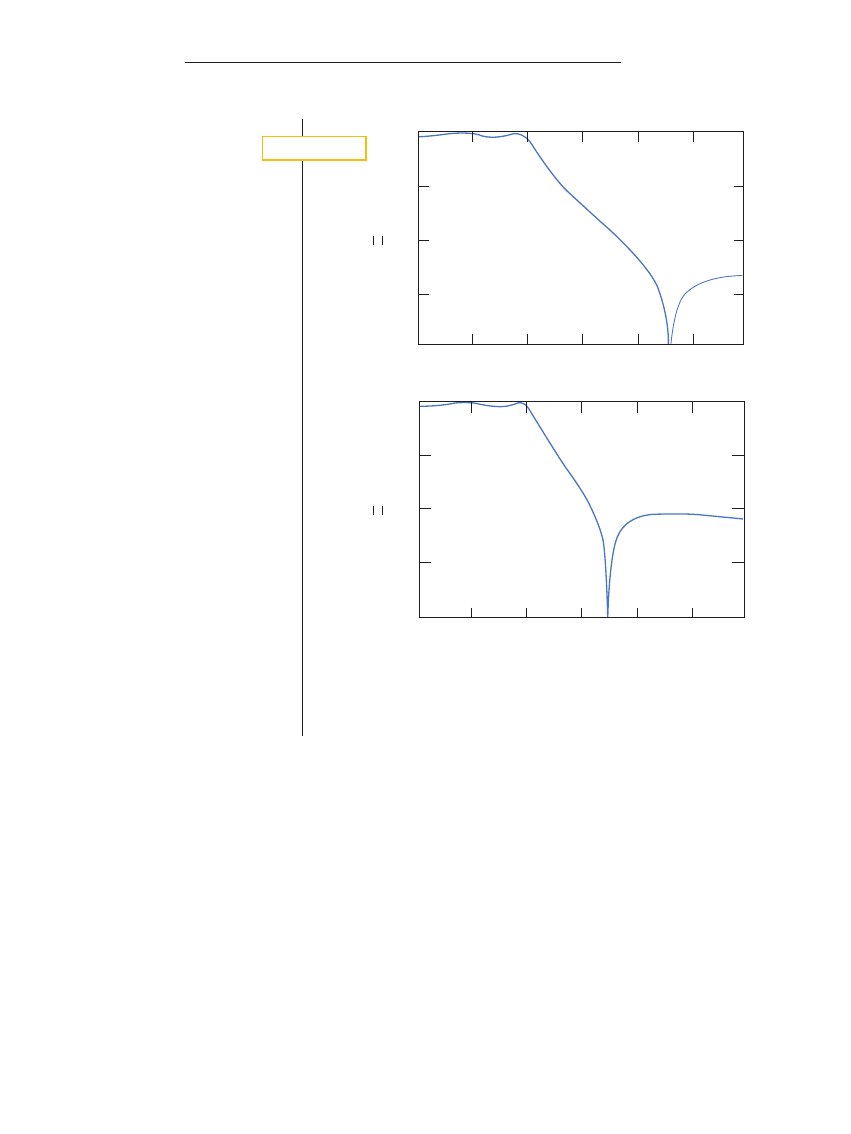
Figure 4a shows the fourth-order el-
liptic filter that meets the requirements.
For this filter, the BES calculated from
Equation 2 is 4.62. The sensitivities are
S
e1
BES
51.25, S
e2
BES
0, and S
Ve
BES
520.67.
To maximize the selectivity of the fil-
ter, you calculate
F
max
5n
i
/n 1.23. Read-
ing this value from Figure 3 at the
V
S
52
curve results in a value reading of
b
51.35. Thus, the required stopband fre-
quency
~
V
S
5V
S
/b
52/1.3551.48.You use
this value as the stopband corner fre-
quency in the design and recalculate the
filter poles and zeros. Figure 4b shows a
plot of the fourth-order filter that meets
the original requirements with maxi-
mum BES. The new BES is 6.36 with new
sensitivity S
Ve
BES
521.68.
A careful observation of Figure 4a and
b highlights the effect of moving in the
stopband corner frequency
V
S
. The orig-
inal specifications resulted in a filter
whose transition band just met the
240-
dB rejection requirement at 2000 Hz
(Figure 4a). The secondary lobe is down
around
253 dB with a notch at 2350 Hz.
The proposed technique moved the
notch closer to the passband to around
1750 Hz (Figure 4b). This notch move-
ment results in an increase of the sec-
ondary lobe up to the required
240-dB
rejection level. However, rejection in the
transition band is superior. For example,
the original filter had 25 dB of rejection
at 1500 Hz. The modified filter has more
than 30 dB of rejection at 1500 Hz.
COMPARE RESPONSE TO CHEBYSHEV FILTER
It is interesting to compare the ellip-
tic filter to the Chebyshev filter, which
like the elliptic filter provides selectivity
that is proportional to n
2
. A seventh-or-
der Chebyshev filter is necessary to meet
this new requirement of
V
S
51.48.
Therefore, the elliptic filter is the clear
winner due to its reduced parts count in
circuit implementations, even when fac-
A fourth-order elliptic filter (a) meets the following filter requirements: passband ripple
5
5
1.25 dB,
stopband rejection
5
5
40 dB, passband frequency
5
5
1000 Hz, and stopband frequency
5
5
2000 Hz.
Another fourth-order elliptic filter (b) not only meets the filter requirements but also exhibits max-
imum selectivity.
0
220
240
260
280
500
1000
1500
2000
2500
3000
f (Hz)
500
1000
1500
2000
2500
3000
f (Hz)
H
0
220
240
260
280
H
(a)
(b)
F i g u r e 4
108
edn | May 25, 2000
toring in the transmission zeros.
Increasing filter selectivity has a neg-
ative impact on the delay response in the
passband. Elliptic filters exhibit less de-
lay variation than Chebyshev filters but
more delay peaking. Negative delay im-
pulses of area
2p appear at the zero fre-
quencies, and the effect of reducing
V
S
simply moves the zero impulses closer to
the transition band. However, to com-
pensate for the zeros, the pole locations
shift closer to the j
v axis. This shift
slightly increases delay variation but se-
verely impacts delay peaking near the
band edge. In addition, if the zeros are
not purely imaginary but lay off the j
v
axis, they would produce negative delay
peaking of nonzero bandwidth, thereby
distorting the delay near the passband
edge.
Reducing
V
S
also impacts the step re-
sponse of elliptic filters. From the plots
in references 7 and 8, the step response
depends on the inverse of the stopband
corner
V
S
for constant in-band ripple.
The low-frequency delay and thus the de-
lay time decreases as
V
S
decreases. In ad-
dition, the overshoot decreases as
V
S
de-
creases. You can explain this fact by
observing that the highest-Q complex-
pole pair moves closer to the imaginary
zeros as
V
S
decreases, which reduces the
residue value for that pole and, therefore,
the overshoot.
For fixed
V
S
, the overshoot increases
with filter order. Therefore, maximizing
selectivity not only reduces step-response
overshoot but also ensures that there is
no increase because the order remains
fixed. Also, the rise time remains rela-
tively constant as long as the 3-dB band-
width is nearly constant, which is a char-
acteristic of high-order filters.
Due to the increase in the filter’s sen-
sitivity to the stopband frequency ratio
V
S
, for practical designs you should se-
lect a value for
~
V
S
that is a little larger
than the value that results in the maxi-
mum selectivity. A few Monte Carlo runs
may be in order to evaluate the filter’s
sensitivity to the higher selectivity.
k
designfeature
Elliptic-filter design
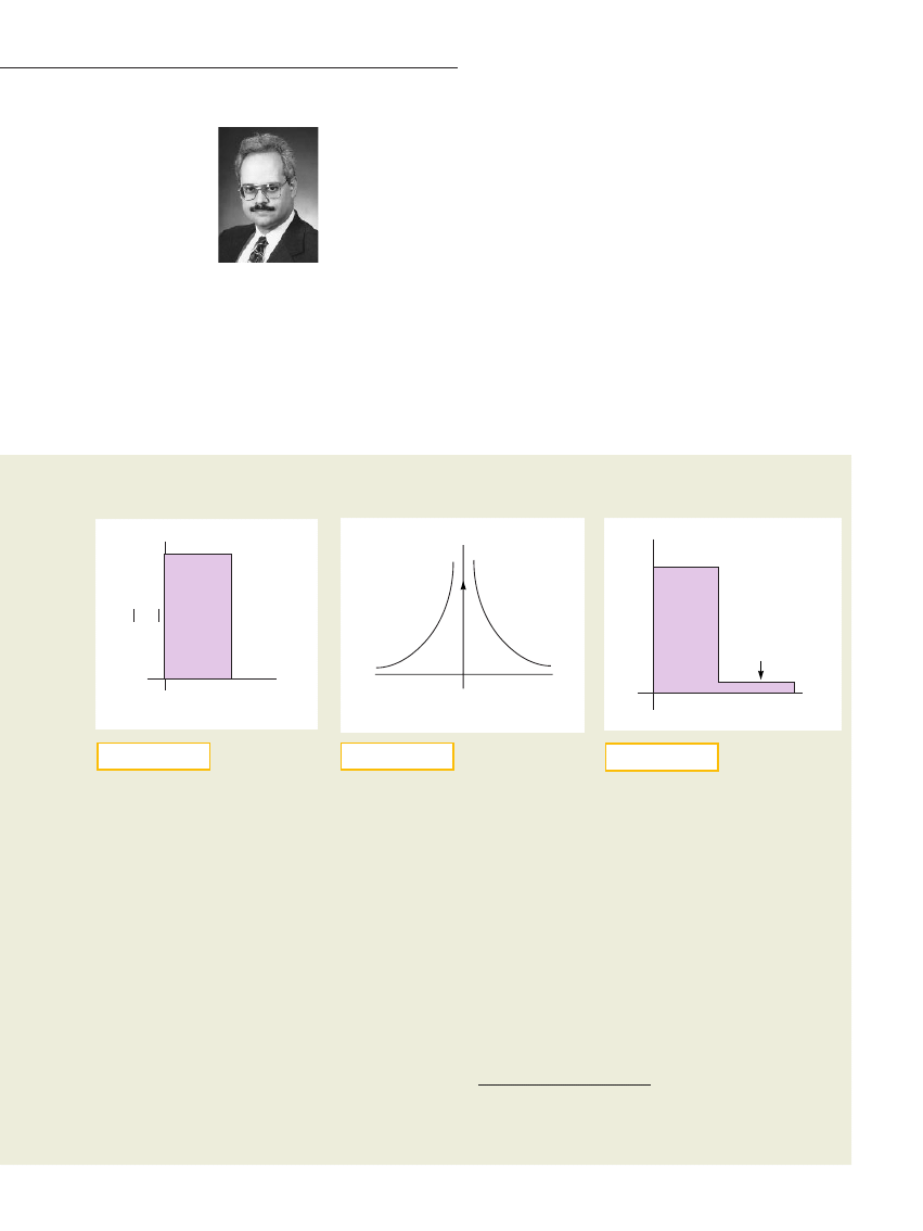
A NEW LOOK AT THE BRICK-WALL FILTER
The brick-wall filter in FFiigguurree AA is
valuable from a theoretical stand-
point because it serves as the stan-
dard for filter approximations.
However, you can never actually
build this brick-wall filter for one
simple reason: Its magnitude re-
sponse is zero over an infinite
band of frequencies. Aside from
the fact that the phase is unde-
fined for a band of zero frequen-
cies, the finite bandwidth of the fil-
ter makes it noncausal, that is, it
has a response without any input.
Indeed, the impulse response of
the brick-wall filter is the sin x/x
function, which extends for all
time.
RReeffeerreennccee AA discusses the rela-
tion between causality, or realiz-
ability, and frequency response,
deriving the following criterion
where H(j
v
) is the frequency re-
sponse of the filter:
This compact formula is difficult to
evaluate except in the simplest
cases, such as the brick-wall filter.
If you let the passband of the
brick-wall filter be unity and ex-
tend to frequency
v
o
, as FFiigguurree AA
shows, then you can break up the
criterion as follows:
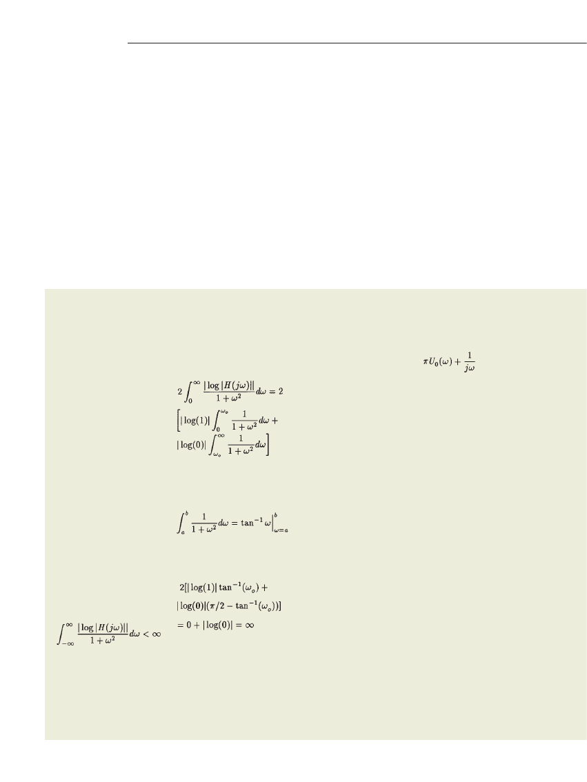
As in RReeffeerreennccee BB, the integral
equals
Therefore,
T h i s
equation violates the Paley-
Wiener criterion, and the brick-
wall filter is not realizable.
It turns out that finite zeros in
the magnitude response—like in
the elliptic filter—are not a prob-
lem. Using the above argument, a
single zero in the magnitude re-
sponse represents a phase or de-
lay discontinuity, which itself is
well-defined. Furthermore, the
zero value of any number of mag-
nitude components, as long as
they are distinct, does not consti-
tute a special problem in the
causality of the impulse response.
The Paley-Wiener criterion pro-
vides a test for a contiguous band
of zeros.
This last point is a fundamental
result of Fourier analysis. For ex-
ample, the spectrum of a period-
ic waveform can have many dis-
crete frequency terms, or
harmonics, that are separated by
bands of zero magnitude. Yet, a
periodic waveform is not causal.
On the other hand, the spectrum
of a time-limited signal results in
an infinite number of frequency
components. Some of the com-
ponents may be zero, but none
are in a contiguous band.
Now look at the problem from
the time domain. If a signal is
causal, then its response is zero for
time
2`,
t
,
t
o
. Let’s assume
t
o
5
0 without any loss of general-
ity. Then you can equivalently state
causality as a signal gated, or mul-
tiplied, by a unit step at time t
o
5
0.
The Fourier transform of the unit
step is (RReeffeerreennccee C
C)
which consists of a function
whose magnitude response varies
as 1/
v
and is centered at
v5
0
with a unit impulse, U
0
, at
v5
0
(FFiigguurree BB). Gating any input signal
causes a convolution of the input
spectrum with the spectrum in
FFiigguurree BB, resulting in frequency
components in all bands because
of the infinite spectrum of the unit
step.
Does this situation mean that if
the input is causal then you can
have a noncausal impulse re-
sponse and have a causal output?
The answer is no. Recall that the
impulse response of the filter con-
volves with the input, so if the im-
pulse response is noncausal, the
output is noncausal.
The discussion thus far shows,
by way of the Paley-Wiener crite-
rion and some basic results of
Fourier analysis, that the brick-wall
filter is not realizable. Now con-
sider modifying the brick-wall fil-
ter by making the stopband mag-
nitude response nonzero and a
constant,
e
(FFiigguurree C
C). If you sub-
stitute this modified brick-wall fil-
ter into the Paley-Wiener criterion,
.
.
.
.
,
Author’s
bio g raphy
Celestino A Corral is
a senior staff electrical
engineer with the
commercial, govern-
ment, and industry
solutions sector of
Motorola Inc (Plantation, FL). He cur-
rently is the technical lead of the simula-
tion and modeling engineering team, but
his career has encompassed many aspects
of analog and RF design as well as software
development. He holds bachelor’s, master’s,
and PhD degrees in electrical engineering
from the University of Miami (Coral
Gables, FL).
References
1. Lindquist, CS, Active Network Design
with Signal Filtering Applications, Stew-
ard & Sons, Long Beach, CA, Chapter 4,
1977.
2. Corral, CA, and CS Lindquist, “On
the band-edge selectivity of elliptic fil-
ters,” to be published in IEE Proceedings
on Circuits, Devices, and Systems.
3. Gorski-Popiel, J, “Classical sensitiv-
ity—A collection of formulas,” IEEE
Transactions on Circuit Theory, Volume
CT-10, June 1963, pg 300.
4. Corral, CA, CS Lindquist and PB
Aronhime, “Sensitivity of the band-edge
selectivity of various classical filters,” Pro-
ceedings of the 40th Midwest Sympo-
sium of Circuits and Systems, August
1997, pg 324.
5. Calahan, DA, Modern Network Syn-
thesis, Volume 1, Hayden, New York, NY,
1964, chapters 2 and 3.
6. Bronshtein, IN, and KA Se-
mendyayev, Handbook of Mathematics,
Van Nostrand-Reinhold, New York, NY,
1985.
7. Holt, AJG, JP Gray, and JK Fidler,
“Transient response of elliptic function
filters,”IEEE Transactions on Circuit The-
ory, Volume CT-15, March 1968, pg 71.
8. Hansell, GE, Filter Design and Eval-
uation, Van Nostrand, New York, NY,
1969.
it is easy to show that the result is
now finite (that is, |log(
e
)| re-
places |log(0)| in the last term),
and you have a causal filter.
This modification essentially
adds a contiguous band of small
magnitude and phase compo-
nents from the stopband. These
components contribute to the im-
pulse response in such a fashion
that the filter is now causal.
You can therefore choose to ap-
proximate the modified brick-wall
filter instead of the ideal brick-wall
filter. This approximation shifts at-
tention from attempting to ap-
proximate something that you
can’t build to attempting to ap-
proximate something that you
can. You can use finite zeros in the
stopband to your advantage. Fur-
thermore, any additional rejection
in the stopband is acceptable. El-
liptic filters excel in these require-
ments, which is why they are so
useful in applications with strin-
gent magnitude-response re-
quirements.
Another interesting point is that
the selectivity of the ideal and
modified brick-wall filters is infi-
nite. Because you can in theory
build a modified brick-wall filter,
infinite selectivity is a worthy and
achievable goal. From the deriva-
tions in this article (see EEqquuaattiioonn
44 of the main text), the elliptic fil-
ter’s selectivity is nearly infinite
when
V
S
P
1. Maximizing selec-
tivity through the proposed
method for higher elliptic-filter or-
ders allows you to approximate
the infinite selectivity of the ideal
brick-wall filter response.
References
A. Paley, Raymond EAC and
Norbert Wiener, “Fourier trans-
forms in the complex domain,’’
American Mathematical Society
Colloquium Publication
, Volume
19, Chapter 1, 1934.
B. Bronshtein, IN and KA Se-
mendyayev, Handbook of Math-
ematics, Van Nostrand-Reinhold,
New York, NY, 1985.
C. Lindquist, CS, Adaptive and
Digital Signal Processing with
Digital Filtering Applications,
Steward & Sons, Miami, FL, 1989.
www.ednmag.com
May 25, 2000 | edn
109
v
0
H(j
v)
1
v
You can’t actually
build this ideal
brick-wall filter because the magnitude
response is zero over an infinite band of
frequencies.
F i g u r e A
U(j
v)
v
0
The Fourier transform
of the unit step consists
of a function whose magnitude response varies
as 1/
v
v
and is centered at
v
v5
5
0 with a unit
impulse U
0
at
v
v5
5
0.
F i g u r e B
H(j
v)
v
0
v
ADDED ERROR
e IN
HIGH-FREQUENCY
BANDS
1
You can make a
brick-wall filter real-
izable by making the stopband magnitude
response nonzero and a constant
ee
.
F i g u r e C
Wyszukiwarka
Podobne podstrony:
Non Intrinsic Differential Mode Noise of Switching Power Supplies and Its Implications to Filter Des
Active Filter Analog Filter Design(1)
Design and Performance of the OpenBSD Statefull Packet Filter Slides
Introduction to EMI filters DESIGN
Efficient VLSI architectures for the biorthogonal wavelet transform by filter bank and lifting sc
History Costume History Costume Design Viking Women
Eurocode 5 EN 1995 1 1 Design Of Timber Structures Part 1 1 General Rules
[Instrukcja] GDOT Design Policy Manual Chapter 8 Roundabouts (USA)
Applications of polyphase filters for bandpass sigma delta analog to digital conversion
100108 nmea 0183 sentences not recommended for new designs
journal design
A New Hybrid Transmission designed for FWD Sports Utility Vehicles
Fine Filters CJC
Programming Designs
DesignSem1
Language Curriculum Design
więcej podobnych podstron