
KUKA.Gripper&SpotTech2.3 07.06.00 en
1 von 56
SOFTWARE
KR C...
KUKA.Gripper-- and SpotTech 2.3
for KUKA System Software (KSS) 5.x, 7.0
Issued: 10 July 2006
Version: 00

2 von 56
KUKA.Gripper&SpotTech2.3 07.06.00 en
e
Copyright
2006
KUKA Roboter GmbH
This documentation or excerpts therefrom may not be reproduced or disclosed to third parties without the express permission of the publishers.
Other functions not described in this documentation may be operable in the controller. The user has no claim to these functions, however, in
the case of a replacement or service work.
We have checked the content of this documentation for conformity with the hardware and software described. Nevertheless, discrepancies
cannot be precluded, for which reason we are not able to guarantee total conformity. The information in this documentation is checked on a
regular basis, however, and necessary corrections will be incorporated in subsequent editions.
Subject to technical alterations without an effect on the function.
KUKA Interleaf

3 von 56
KUKA.Gripper&SpotTech2.3 07.06.00 en
Contents
1
General
6
. . . . . . . . . . . . . . . . . . . . . . . . . . . . . . . . . . . . . . . . . . . . . . . . . . . . . . . . .
2
Installation / uninstallation / update
7
. . . . . . . . . . . . . . . . . . . . . . . . . . . . . . .
3
GripperTech
8
. . . . . . . . . . . . . . . . . . . . . . . . . . . . . . . . . . . . . . . . . . . . . . . . . . . . .
3.1
Basic gripper functions
8
. . . . . . . . . . . . . . . . . . . . . . . . . . . . . . . . . . . . . . . . . . . . . . . . . . . . . . . . .
3.1.1
Type 1
2 outputs, 4 inputs, 2 switching states
8
. . . . . . . . . . . . . . . . . . . . . . . . . . . . . . . . . . .
3.1.2
Type 2
2 outputs, 2 inputs, 3 switching states
8
. . . . . . . . . . . . . . . . . . . . . . . . . . . . . . . . . . .
3.1.3
Type 3
2 outputs, 2 inputs, 3 switching states
8
. . . . . . . . . . . . . . . . . . . . . . . . . . . . . . . . . . .
3.1.4
Type 4
3 outputs, 2 inputs, 3 switching states
8
. . . . . . . . . . . . . . . . . . . . . . . . . . . . . . . . . . .
3.1.5
Type 5
2 outputs, 4 inputs, 2 switching states
9
. . . . . . . . . . . . . . . . . . . . . . . . . . . . . . . . . . .
3.1.6
Freely programmable type
9
. . . . . . . . . . . . . . . . . . . . . . . . . . . . . . . . . . . . . . . . . . . . . . . . . . . . . .
3.1.6.1 Programming example
9
. . . . . . . . . . . . . . . . . . . . . . . . . . . . . . . . . . . . . . . . . . . . . . . . . . . . . . . . . .
3.1.7
Initialization and configuration examples
13
. . . . . . . . . . . . . . . . . . . . . . . . . . . . . . . . . . . . . . . . . .
3.2
Manually operating a gripper
14
. . . . . . . . . . . . . . . . . . . . . . . . . . . . . . . . . . . . . . . . . . . . . . . . . . . .
3.3
Programming gripper functions
15
. . . . . . . . . . . . . . . . . . . . . . . . . . . . . . . . . . . . . . . . . . . . . . . . . .
3.3.1
Gripper
15
. . . . . . . . . . . . . . . . . . . . . . . . . . . . . . . . . . . . . . . . . . . . . . . . . . . . . . . . . . . . . . . . . . . . . . .
3.3.2
Check Gripper
18
. . . . . . . . . . . . . . . . . . . . . . . . . . . . . . . . . . . . . . . . . . . . . . . . . . . . . . . . . . . . . . . . .
4
SpotTech
20
. . . . . . . . . . . . . . . . . . . . . . . . . . . . . . . . . . . . . . . . . . . . . . . . . . . . . . . .
4.1
Basic SpotTech user functions
20
. . . . . . . . . . . . . . . . . . . . . . . . . . . . . . . . . . . . . . . . . . . . . . . . . . .
4.1.1
Range of commands
20
. . . . . . . . . . . . . . . . . . . . . . . . . . . . . . . . . . . . . . . . . . . . . . . . . . . . . . . . . . .
4.1.2
The functions SPOT and RETRACT
20
. . . . . . . . . . . . . . . . . . . . . . . . . . . . . . . . . . . . . . . . . . . . . .
4.2
Programming and operation
21
. . . . . . . . . . . . . . . . . . . . . . . . . . . . . . . . . . . . . . . . . . . . . . . . . . . . .
4.2.1
General information on programming
21
. . . . . . . . . . . . . . . . . . . . . . . . . . . . . . . . . . . . . . . . . . . . .
4.2.1.1 Variables in input boxes of the inline forms
21
. . . . . . . . . . . . . . . . . . . . . . . . . . . . . . . . . . . . . . . .
4.2.1.2 Overview of the inline forms
21
. . . . . . . . . . . . . . . . . . . . . . . . . . . . . . . . . . . . . . . . . . . . . . . . . . . . .
4.2.2
Spot welding (SPOT)
22
. . . . . . . . . . . . . . . . . . . . . . . . . . . . . . . . . . . . . . . . . . . . . . . . . . . . . . . . . . .
4.2.3
Types of motion
22
. . . . . . . . . . . . . . . . . . . . . . . . . . . . . . . . . . . . . . . . . . . . . . . . . . . . . . . . . . . . . . .
4.2.3.1 Point--to--point (PTP) motion
22
. . . . . . . . . . . . . . . . . . . . . . . . . . . . . . . . . . . . . . . . . . . . . . . . . . . . .
4.2.3.2 Motion along a straight line (LIN)
22
. . . . . . . . . . . . . . . . . . . . . . . . . . . . . . . . . . . . . . . . . . . . . . . . .
4.2.3.3 Motion along a circular path (CIRC)
22
. . . . . . . . . . . . . . . . . . . . . . . . . . . . . . . . . . . . . . . . . . . . . .
4.2.3.4 Activating/deactivating collision detection
22
. . . . . . . . . . . . . . . . . . . . . . . . . . . . . . . . . . . . . . . . . .
4.2.4
Programming a weld spot (SPOT)
23
. . . . . . . . . . . . . . . . . . . . . . . . . . . . . . . . . . . . . . . . . . . . . . . .
4.2.4.1 Menu
23
. . . . . . . . . . . . . . . . . . . . . . . . . . . . . . . . . . . . . . . . . . . . . . . . . . . . . . . . . . . . . . . . . . . . . . . . .
4.2.4.2 The inline form and the parameter lists for the welding command “SPOT”
24
. . . . . . . . . . . . .
4.2.4.3 Selecting the welding gun (Gun = n)
25
. . . . . . . . . . . . . . . . . . . . . . . . . . . . . . . . . . . . . . . . . . . . . .
4.2.4.4 Retract stroke after the welding process (RETR OPN / CLO)
25
. . . . . . . . . . . . . . . . . . . . . . . .
4.2.4.5 Weld parameter list
25
. . . . . . . . . . . . . . . . . . . . . . . . . . . . . . . . . . . . . . . . . . . . . . . . . . . . . . . . . . . .
4.2.5
Opening/closing the welding gun retract stroke (RETRACT)
26
. . . . . . . . . . . . . . . . . . . . . . . . .
4.2.5.1 Types of motion
27
. . . . . . . . . . . . . . . . . . . . . . . . . . . . . . . . . . . . . . . . . . . . . . . . . . . . . . . . . . . . . . .
4.2.5.2 Programming the retract stroke (RETRACT)
27
. . . . . . . . . . . . . . . . . . . . . . . . . . . . . . . . . . . . . . .
4.2.6
Motion commands
29
. . . . . . . . . . . . . . . . . . . . . . . . . . . . . . . . . . . . . . . . . . . . . . . . . . . . . . . . . . . . .
4.2.7
Reorientation of the welding gun
30
. . . . . . . . . . . . . . . . . . . . . . . . . . . . . . . . . . . . . . . . . . . . . . . . .
4.3
Program example
31
. . . . . . . . . . . . . . . . . . . . . . . . . . . . . . . . . . . . . . . . . . . . . . . . . . . . . . . . . . . . . .
4.3.1
Creating a new program
31
. . . . . . . . . . . . . . . . . . . . . . . . . . . . . . . . . . . . . . . . . . . . . . . . . . . . . . . .

KUKA.Gripper-- and SpotTech 2.3
4 von 56
KUKA.Gripper&SpotTech2.3 07.06.00 en
4.3.1.1 Welding the first spot sequence
35
. . . . . . . . . . . . . . . . . . . . . . . . . . . . . . . . . . . . . . . . . . . . . . . . . .
4.3.1.2 Welding the second spot sequence
36
. . . . . . . . . . . . . . . . . . . . . . . . . . . . . . . . . . . . . . . . . . . . . . .
4.3.1.3 Moving from the end of the spot seam to the home position
36
. . . . . . . . . . . . . . . . . . . . . . . . . .
4.4
Altering existing programs
37
. . . . . . . . . . . . . . . . . . . . . . . . . . . . . . . . . . . . . . . . . . . . . . . . . . . . . . .
4.4.1
Altering command lines
37
. . . . . . . . . . . . . . . . . . . . . . . . . . . . . . . . . . . . . . . . . . . . . . . . . . . . . . . . .
4.4.2
Deleting command lines
37
. . . . . . . . . . . . . . . . . . . . . . . . . . . . . . . . . . . . . . . . . . . . . . . . . . . . . . . .
4.4.3
Adding commands to an existing program
38
. . . . . . . . . . . . . . . . . . . . . . . . . . . . . . . . . . . . . . . . .
4.4.3.1 Description of the alteration
39
. . . . . . . . . . . . . . . . . . . . . . . . . . . . . . . . . . . . . . . . . . . . . . . . . . . . .
4.4.3.2 Changing the position of the welding gun (point in space P10)
39
. . . . . . . . . . . . . . . . . . . . . . . .
4.4.3.3 Reorientation of the welding gun -- inserting the command “Motion” (P11)
39
. . . . . . . . . . . . . .
4.4.3.4 Moving to the point in space P12 -- inserting the command “Motion”
40
. . . . . . . . . . . . . . . . . . .
4.4.3.5 Welding spot P13 -- inserting the command “SPOT”
40
. . . . . . . . . . . . . . . . . . . . . . . . . . . . . . . .
4.4.3.6 Moving to the weld spot P16 and welding
40
. . . . . . . . . . . . . . . . . . . . . . . . . . . . . . . . . . . . . . . . .
4.4.3.7 Moving to the home position
40
. . . . . . . . . . . . . . . . . . . . . . . . . . . . . . . . . . . . . . . . . . . . . . . . . . . . .
4.5
SpotTech configuration
41
. . . . . . . . . . . . . . . . . . . . . . . . . . . . . . . . . . . . . . . . . . . . . . . . . . . . . . . . .
4.5.1
Program sequence
41
. . . . . . . . . . . . . . . . . . . . . . . . . . . . . . . . . . . . . . . . . . . . . . . . . . . . . . . . . . . . .
4.5.2
Retract stroke (RETRACT) and working stroke (SPOT)
42
. . . . . . . . . . . . . . . . . . . . . . . . . . . . .
4.5.3
Early closing of the gun (PRESPOT)
42
. . . . . . . . . . . . . . . . . . . . . . . . . . . . . . . . . . . . . . . . . . . . .
4.6
Components of the SpotTech package
44
. . . . . . . . . . . . . . . . . . . . . . . . . . . . . . . . . . . . . . . . . . . .
4.6.1
Program structure
44
. . . . . . . . . . . . . . . . . . . . . . . . . . . . . . . . . . . . . . . . . . . . . . . . . . . . . . . . . . . . . .
4.6.2
SPOT Tech--specific files
44
. . . . . . . . . . . . . . . . . . . . . . . . . . . . . . . . . . . . . . . . . . . . . . . . . . . . . . . .
4.7
Adaptation to the periphery, configurable options
45
. . . . . . . . . . . . . . . . . . . . . . . . . . . . . . . . . . .
4.7.1
FOLD “SPOT” in the file “$CONFIG.DAT”
45
. . . . . . . . . . . . . . . . . . . . . . . . . . . . . . . . . . . . . . . . .
4.7.2
The user--specific program “USERSPOT.SRC”
46
. . . . . . . . . . . . . . . . . . . . . . . . . . . . . . . . . . . . .
4.7.2.1 Schematic sequence diagram for SPOT (without RETRACT)
47
. . . . . . . . . . . . . . . . . . . . . . . .
4.7.2.2 Schematic sequence diagram for SPOT (with RETRACT)
48
. . . . . . . . . . . . . . . . . . . . . . . . . . .
4.7.2.3 Robot controller -- welding controller interface
49
. . . . . . . . . . . . . . . . . . . . . . . . . . . . . . . . . . . . . .
4.7.2.4 Program example for the file “USERSPOT.SRC”
49
. . . . . . . . . . . . . . . . . . . . . . . . . . . . . . . . . . .
4.8
Program example
52
. . . . . . . . . . . . . . . . . . . . . . . . . . . . . . . . . . . . . . . . . . . . . . . . . . . . . . . . . . . . . .
4.9
Manual operation of the welding gun using the status keys
53
. . . . . . . . . . . . . . . . . . . . . . . . . .
4.9.1
Separate control of RETRACT and SPOT
53
. . . . . . . . . . . . . . . . . . . . . . . . . . . . . . . . . . . . . . . . .
4.9.1.1 Definition of function type and assignment of physical outputs
53
. . . . . . . . . . . . . . . . . . . . . . . .
4.9.2
Manual control of RETRACT and SPOT in series
55
. . . . . . . . . . . . . . . . . . . . . . . . . . . . . . . . . .

5 von 56
KUKA.Gripper&SpotTech2.3 07.06.00 en

KUKA.Gripper-- and SpotTech 2.3
6 von 56
KUKA.Gripper&SpotTech2.3 07.06.00 en
1
General
The software packages GripperTech and SpotTech are supplied together on a Setup CD and
expand the scope of the basic KRC software.
-- The functions of the GripperTech technology package (gripper programming) enable the
robot system to control and monitor tools and devices in its work environment.
-- The SpotTech technology package is used for the convenient programming of spot welding
applications.
2
Installation / uninstallation / update
7 von 56
KUKA.Gripper&SpotTech2.3 07.06.00 en
2
Installation / uninstallation / update
From system software version 5.1 onwards, technology packages are offered exclusively as
add--on software modules. These are available on CD--ROM. Should you be interested in
purchasing further modules, please contact KUKA Support.
The installation procedure is the same for all technology packages and is described in a
separate documentation module.
The installation, uninstallation, reinstallation and update of technology packages
are described in detail in the documentation “Installation/Uninstallation/Update of
Tech Packages”.
KUKA.Gripper-- and SpotTech 2.3
8 von 56
KUKA.Gripper&SpotTech2.3 07.06.00 en
3
GripperTech
3.1
Basic gripper functions
The GripperTech technology package includes five basic types of gripper control, with whose
logic functions the majority of applications that occur are covered. If these basic types prove
to be insufficient at any time, any additional gripper functions can be freely programmed.
Each gripper must be assigned a function type. If a gripper is to be temporarily or
permanently excluded from use, it must be assigned gripper type “0”.
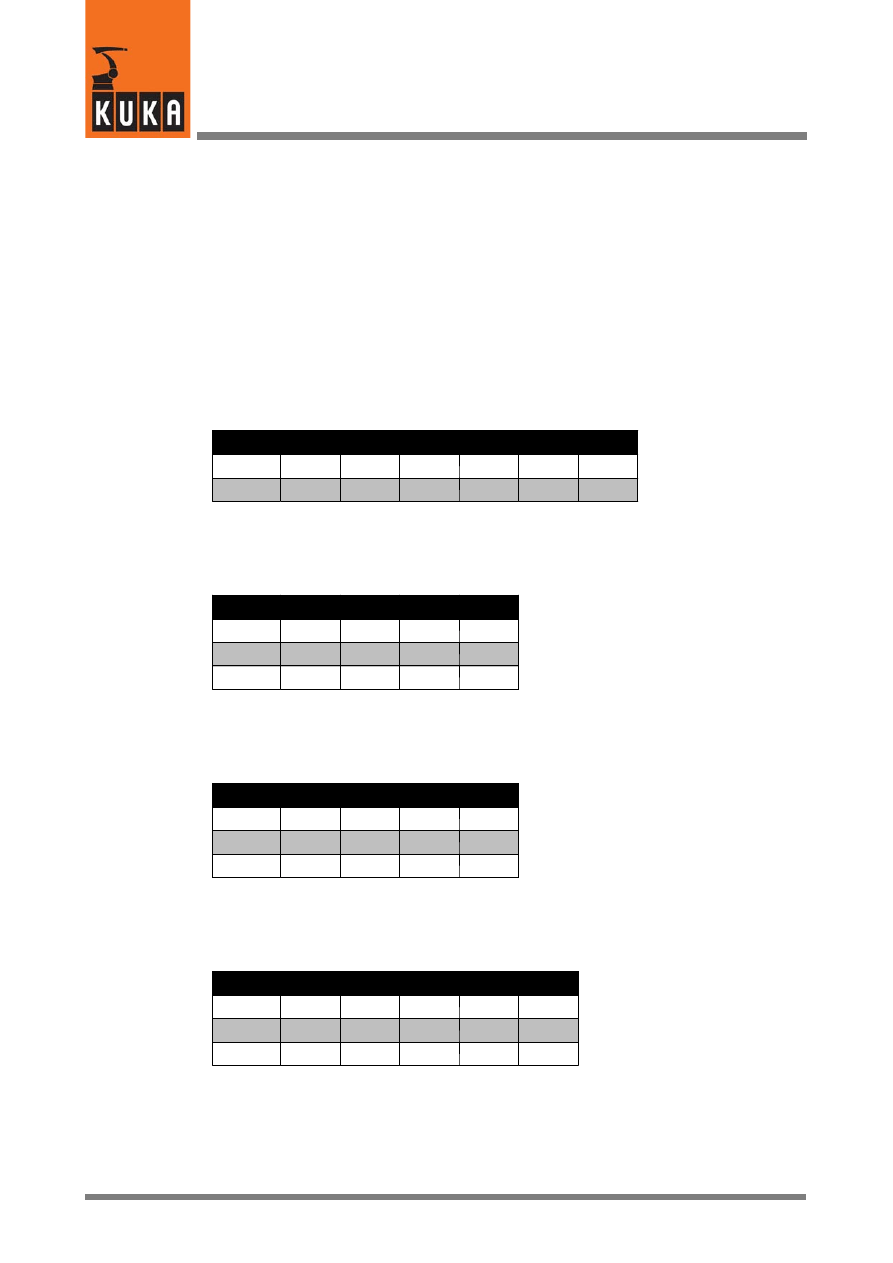
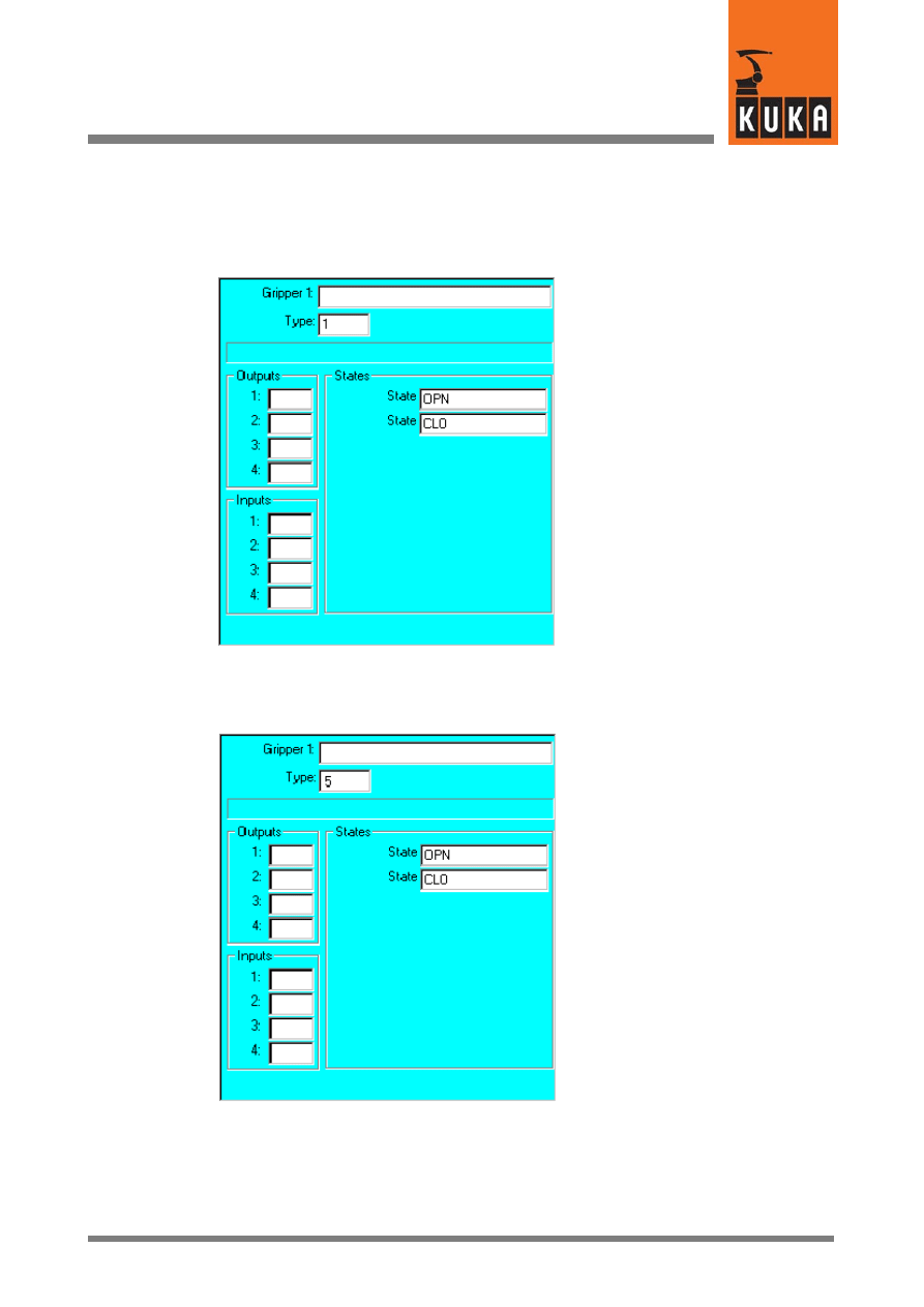
3.1.1
Type 1
2 outputs, 4 inputs, 2 switching states
e.g. a simple gripper with the functions OPEN and CLOSE;
State
OUT1
OUT2
IN1
IN2
IN3
IN4
A
TRUE FALSE TRUE FALSE TRUE FALSE
B
FALSE TRUE FALSE TRUE FALSE TRUE
3.1.2
Type 2
2 outputs, 2 inputs, 3 switching states
e.g. a slide with a center position;
State
OUT1
OUT2
IN1
IN2
A
TRUE FALSE TRUE FALSE
B
FALSE TRUE FALSE TRUE
C
FALSE FALSE FALSE FALSE
3.1.3
Type 3
2 outputs, 2 inputs, 3 switching states
e.g. a vacuum gripper with the functions VACUUM, BLOW and OFF;
State
OUT1
OUT2
IN1
IN2
A
TRUE FALSE TRUE FALSE
B
FALSE TRUE FALSE TRUE
C
FALSE FALSE FALSE FALSE
3.1.4
Type 4
3 outputs, 2 inputs, 3 switching states
The same as type 3 but with three control outputs (type 3 has two outputs);
State
OUT1
OUT2
OUT3
IN1
IN2
A
TRUE FALSE FALSE TRUE FALSE
B
FALSE TRUE
TRUE FALSE TRUE
C
FALSE TRUE FALSE FALSE FALSE
3
GripperTech (Fortsetzung)
9 von 56
KUKA.Gripper&SpotTech2.3 07.06.00 en
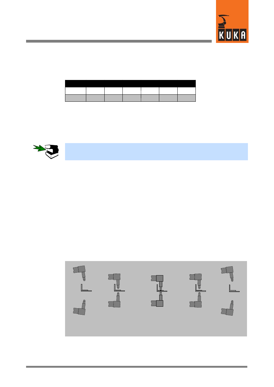
3.1.5
Type 5
2 outputs, 4 inputs, 2 switching states
The same as type 1 but with a pulse signal instead of a continuous signal.
State
OUT1
OUT2
IN1
IN2
IN3
IN4
A
TRUE FALSE TRUE FALSE TRUE FALSE
B
FALSE TRUE FALSE TRUE FALSE TRUE
In contrast to gripper type 1, a continuous signal is not applied here, but a pulse of variable
duration is transmitted whenever the signal level changes. It is set by modifying the variable
GRP_PULSE_TI.
During controller operation, this variable can be altered by means of the “Modify” -- “Variable”
options in the “Monitor” menu.
More detailed information on how to modify the values of system variables during controller
operation can be found in the chapter “Monitor Functions”, section “Variables”.
3.1.6
Freely programmable type
A freely programmable gripper type has been integrated in order to cover all user require-
ments. Any number of completely freely definable grippers can be configured by means of
entries in the files $CONFIG.DAT, USERGRP.DAT and USER_GRP.SRC.
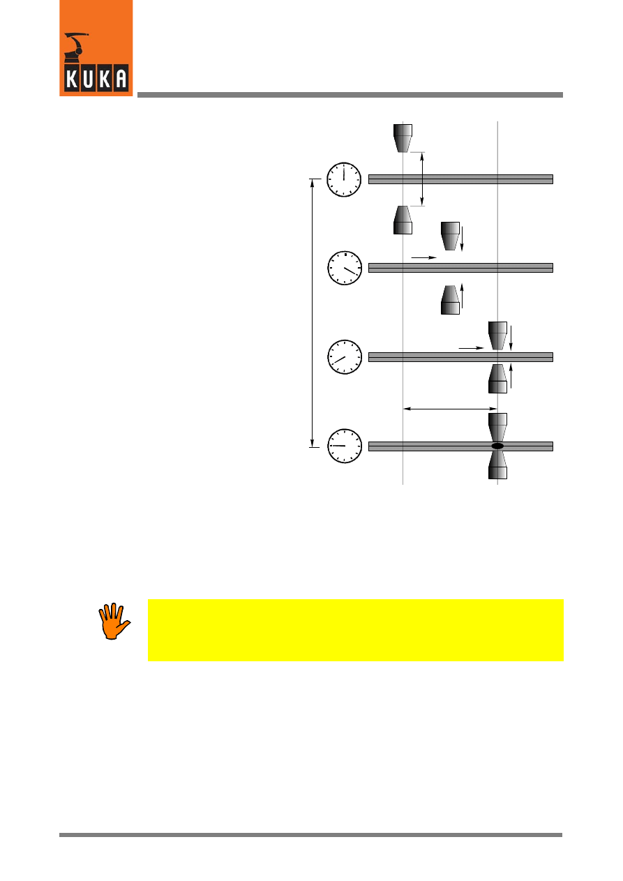
3.1.6.1 Programming example
Requirement
A welding gun is to switch between the positions OPEN -- RETRACT -- WORKING STROKE
-- RETRACT -- OPEN when the status key “Manual gripper operation” is pressed.
OPEN
RETRACT
WORKING STROKE
RETRACT
OPEN
Position “A”
Position “B”
Position “C”
Position “B”
Position “A”
This task requires the use of two double--acting pneumatic cylinders controlled via electro-
magnetically operated 4/2--way valves.
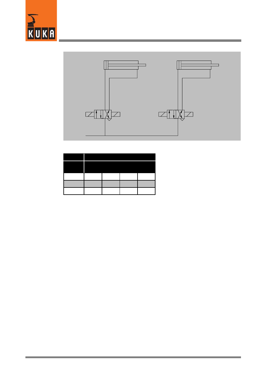
KUKA.Gripper-- and SpotTech 2.3
10 von 56
KUKA.Gripper&SpotTech2.3 07.06.00 en
Retract cylinder
Working stroke cylinder
Output 1
Output 2
Output 3
Output 4
State
Control
Out-
put1
Out-
put2
Out-
put3
Out-
put4
A
FALSE TRUE FALSE TRUE
B
TRUE FALSE FALSE TRUE
C
TRUE FALSE TRUE FALSE
Programming
In order to implement the example described, make the following changes or additions to the
data shown below.
Entries in the file “$CONFIG.DAT”
The freely programmable gripper is defined with the identification number “100”.
;==================================
; Definition of grippers
;==================================
DECL GRP_TYPES GRIPPER[8]
GRIPPER[1]={TYPE 100}
Entries in the file “$USER_GRP.DAT”:
&ACCESS
RP
&COMMENT USER GRIPPER package
DEFDAT
USER_GRP
...
ENUM GUN_STAT RET_OPN,RET_CLS,WRK_CLS,WRK_OPN
Data type, enumeration of gun states:

3
GripperTech (Fortsetzung)
11 von 56
KUKA.Gripper&SpotTech2.3 07.06.00 en
STRUC MY_GUN INT RET_OPN,RET_CLS,WRK_OPN,WRK_CLS,GUN_STAT
STAT
Structure of the user--defined data type “MY_GUN”:
DECL MY_GUN MY_GUN1={RET_OPN 100,RET_CLS 101,WRK_OPN
102,WRK_CLS 103,STAT #RET_OPN}
Assignment of outputs for the welding gun “MY_GUN1” of type “MY_GUN”:
...
ENDDAT
Entries in the file ”USER_GRP.SRC”
DEF
GRP_MANUAL ( ) ;=================
;part for manual functions
;=====================================
SWITCH
GRIPPER[G_NO].TYPE ;switch type of gripper
;end of example for new gripper
CASE 100
$OUT[MY_GUN1.RET_OPN]=FALSE
Reset output
$OUT[MY_GUN1.RET_CLS]=FALSE
Reset output
$OUT[MY_GUN1.WRK_OPN]=FALSE
Reset output
$OUT[MY_GUN1.WRK_CLS]=FALSE
Reset output
SWITCH MY_GUN1.STAT
Start of the control structure
CASE #RET_OPN
If the state of the gun
MY_GUN1.STAT has the value
#RET_OPN (retract stroke
open)
PULSE($OUT[MY_GUN1.RET_CLS],TRUE,0.3) send a 0.3 second
pulse to the output
RET_CLS (retract stroke
closes)
MY_GUN1.STAT=#RET_CLS
set the state of the gun
MY_GUN1.STAT to
#RET_CLS (retract
stroke closed)
CASE #RET_CLS
If the state of the gun
MY_GUN1.STAT has the value
#RET_CLS (retract stroke
closed)
PULSE($OUT[MY_GUN1.WRK_CLS],TRUE,0.3) send a 0.3 second
pulse to the output
WRK_CLS (working
stroke closes)
MY_GUN1.STAT=#WRK_CLS
set the state of the gun
MY_GUN1.STAT
to #WRK_CLS (working

KUKA.Gripper-- and SpotTech 2.3
12 von 56
KUKA.Gripper&SpotTech2.3 07.06.00 en
stroke closed)
CASE #WRK_CLS
If the state of the gun
MY_GUN1.STAT has the value
WRK_CLS (working stroke
closed)
PULSE($OUT[MY_GUN1.WRK_OPN],TRUE,0.3) send a 0.3 second
pulse to the output
WRK_OPN (working
stroke opens)
MY_GUN1.STAT=#WRK_OPN
set the state of the gun
MY_GUN1.STAT to
#WRK_OPN (working
stroke open)
CASE #WRK_OPN
If the state of the gun
MY_GUN1.STAT has the value
#WRK_OPN (working stroke
open)
PULSE($OUT[MY_GUN1.RET_OPN],TRUE,0.3) send a 0.3 second
pulse to the output
RET_OPN (retract stroke
opens)
MY_GUN1.STAT=#RET_OPN
set the state of the gun
MY_GUN1.STAT to
#RET_OPN (retract
stroke open)
DEFAULT
If none of the states listed so
far appears, execute the
following instructions
ENDSWITCH
End of the control structure
...
3
GripperTech (Fortsetzung)
13 von 56
KUKA.Gripper&SpotTech2.3 07.06.00 en
3.1.7
Initialization and configuration examples
On switching to state “A”
(Open), output 17 will be set
to TRUE and output 18
(inverted) also to TRUE.
When scanned, input 22
must have the state TRUE
and input 23 the state FALSE
so that the motion program
can continue.
On switching to state “B”
(Closed), output 17 will be
set to FALSE and output 18
(inverted) also to FALSE.
When scanned, input 22
must have the state FALSE
and input 23 the state TRUE
so that the motion program
can continue.
Not defined
17
--18
0
0
22
23
0
0
Example_1
On switching to state “A”
(Open), output 19 will be set
to TRUE and output 21 to
FALSE. When scanned,
input 22 must have the state
TRUE, input 23 (inverted)
the state TRUE, input 24 the
state TRUE and input 25
(inverted) also the state
TRUE so that the motion
program can continue.
On switching to state “B”
(Closed), output 19 will be
set to FALSE and output 21
to TRUE. When scanned,
input 22 must have the state
FALSE, input 23 (inverted)
also the state FALSE, input
24 the state FALSE and input
25 (inverted) also the state
FALSE so that the motion
program can continue.
Not defined
19
21
0
0
22
--23
24
--25
Example_2
KUKA.Gripper-- and SpotTech 2.3
14 von 56
KUKA.Gripper&SpotTech2.3 07.06.00 en
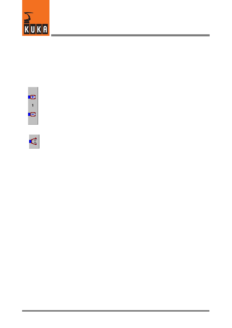
3.2
Manually operating a gripper
A configured gripper can only be operated in the modes:
G
TEST1 (reduced velocity) or
G
TEST2 (programmed velocity),
with an enabling switch being held down.
Use the top status key shown on the left to select from the configured grippers the one that
you would like to operate.
You can then switch between the gripper functions using the bottom status key shown on the
left.
15 von 56
KUKA.Gripper&SpotTech2.3 07.06.00 en
3.3
Programming gripper functions
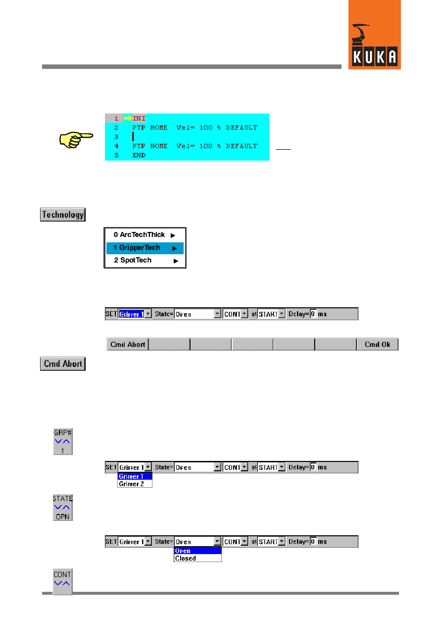
Pay attention to the position of the edit
cursor. The next program line created
by you will be inserted as a new line
after the cursor.
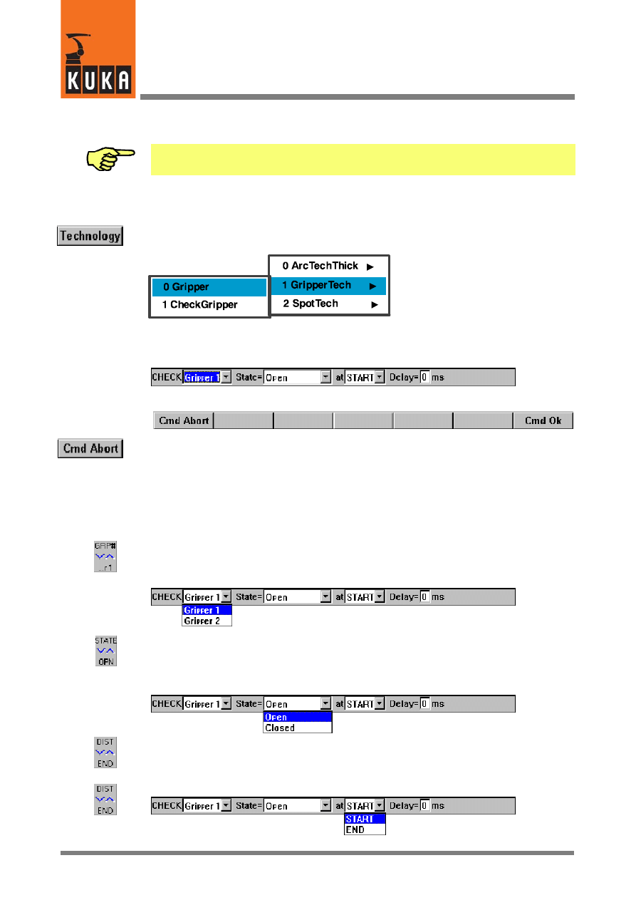
3.3.1
Gripper
Open the menu using the menu key “Technology”. Then select “GRIPPERTech”. The follow-
ing submenu is displayed:
As a gripper function is to be programmed, confirm the offered selection “Gripper”.
An inline form for entering the parameters that are required for executing a gripper function
is opened in the programming window.
The assignment of the softkey bar changes at the same time:
It is possible to abort programming of the gripper function at any time by pressing the softkey
“Cmd Abort” or the ESC key. The command will not be saved in this case.
If the programming window is in focus, the various input windows can be selected using the
“↑” and “↓” arrow keys. The window that is currently selected is highlighted by a color back-
ground.
The programming window can be activated by repeatedly pressing the “Window selection”
key until the entire window is highlighted in color.
Move the cursor to the input box “SET”. The status key (at the bottom right of the display)
changes its assignment.
You can choose between the configured grippers using this status key.
Move the cursor to the input box “State”. The status key (at the bottom right of the display)
changes its assignment.
You can use this status key to choose between the functions that have been defined for the
selected gripper.
Move the cursor to the next input box on the right. The status key (at the bottom right of the
display) changes its assignment.
KUKA.Gripper-- and SpotTech 2.3
16 von 56
KUKA.Gripper&SpotTech2.3 07.06.00 en
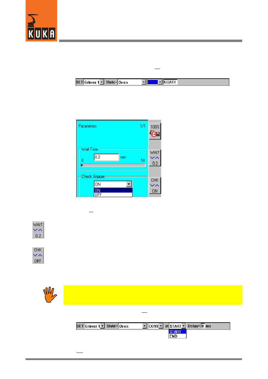
The approximate positioning function can be switched on or off using this status key.
If you switch the approximation function off, a further input box, “GDATn”, appears on
the right, in this case GDAT1.
If the cursor is moved to this box with the “↓” arrow key, a status window is opened.
Data that more precisely characterize the gripper function must be entered here.
Activate this status window using the “Window selection” key.
Decide at this point whether any sensors that may be fitted on the gripper are to be
interrogated or whether a wait time is to be used to ensure that the functions that have been
programmed are fully executed.
Wait Time:
If “Check Gripper” is switched off because, for example, it is not possible to interrogate the
sensors, a wait time of up to ten seconds can be defined here.
Check Gripper:
Here you can specify whether the sensors on the gripper are to be interrogated before the
robot starts moving again (it is only possible to interrogate the sensors if approximate
positioning is switched off in this block). If the sensors do not return a status message, the
controller allows you to set the inputs so that execution of the program can continue
unhindered.
Only use this simulation if you are sure that it cannot result in any unexpected
situations!
If you switch the approximation function on, two further input boxes, “at” and “Delay”, appear
on the right.
Other than in the case of the gripper function without approximation, the robot does
not stop here after reaching the end point in order to activate the gripper.
17 von 56
KUKA.Gripper&SpotTech2.3 07.06.00 en
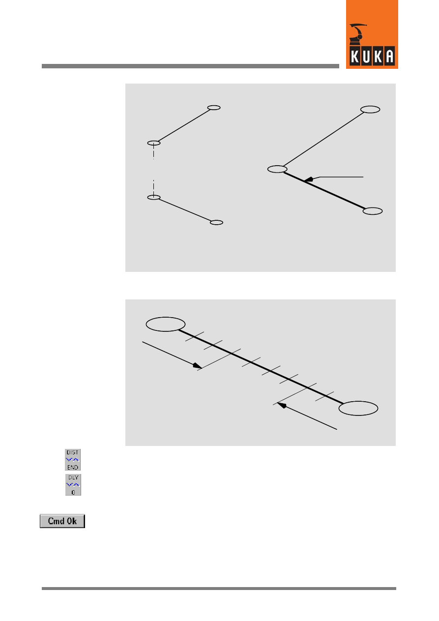
Motion block
1
End point
Execute gripper
function
Without approximate
positioning
The gripper function
is executed along
this line
Motion block
1
Motion block
2
Motion block
2
End point
End point
End point
With approximate
positioning
The parameters START, END and Delay are used to define the point at which the
gripper function is executed.
START
END
Delay
positive
Delay
negative
The reference point for activation of the gripper is determined using the status key (at
the bottom, to the right of the display).
Then move the cursor to the box “Delay”. You can enter a value here, using the
numeric keypad, or change the default value by increments of 1 ms using the status
key (at the bottom, to the right of the display).
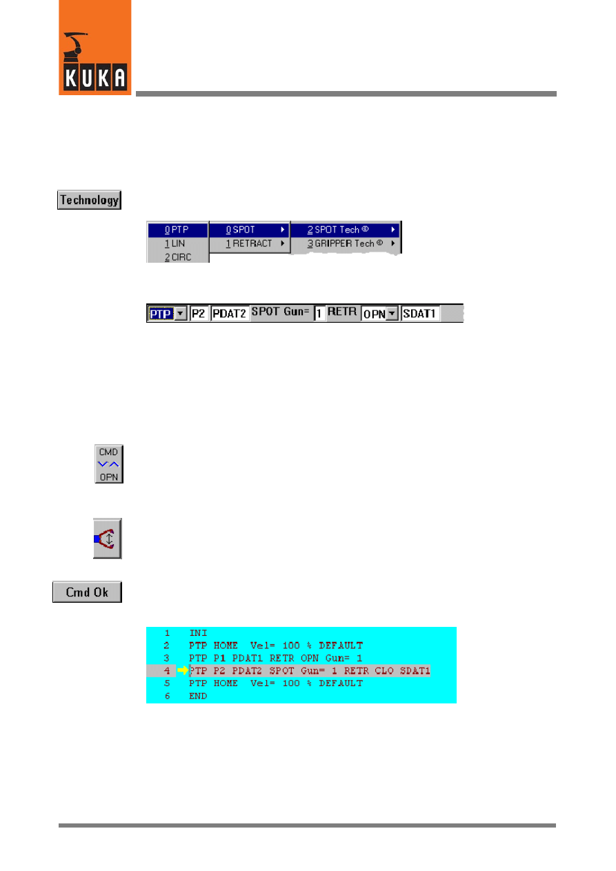
Then press the softkey “Cmd Ok”. The gripper function is now fully programmed and saved.
KUKA.Gripper-- and SpotTech 2.3
18 von 56
KUKA.Gripper&SpotTech2.3 07.06.00 en
3.3.2
Check Gripper
This command is only executed if it is located before a motion instruction.
Any sensors fitted on the gripper can be interrogated using this command. If the conditions
defined by the function type and configuration of the gripper are not satisfied, the robot stops
moving. It does not continue the motion program until the conditions are met.
Now open the menu by means of the menu key “Technology”. Then select “GRIPPERTech”.
(The menu items contained in this menu depend on the specific software configuration.)
As a gripper sensor interrogation is to be programmed, select the option “Check Gripper”.
The inline form for entering the parameters that are required for executing a gripper sensor
interrogation is opened in the programming window.
The assignment of the softkey bar changes at the same time:
It is possible to abort programming of the gripper sensor interrogation at any time by pressing
the softkey “Cmd Abort” or the ESC key. The command will not be saved in this case.
If the programming window is in focus, the various input windows can be selected using the
“↑” and “↓” arrow keys. The window that is currently selected is highlighted by a color back-
ground.
The programming window can be activated by repeatedly pressing the “Window selection”
key until the entire window is highlighted in color.
Move the cursor to the input box “CHECK”. The status key (at the bottom right of the display)
changes its assignment.
You can choose between the configured grippers using this status key.
Move the cursor to the input box “State”. The status key (at the bottom right of the display)
changes its assignment.
You can use this status key to choose between the functions that have been defined for the
selected gripper.
Move the cursor to the input box “at”. The status key (at the bottom right of the display)
changes its assignment.
The reference point for the gripper interrogation is determined using this status key.
19 von 56
KUKA.Gripper&SpotTech2.3 07.06.00 en
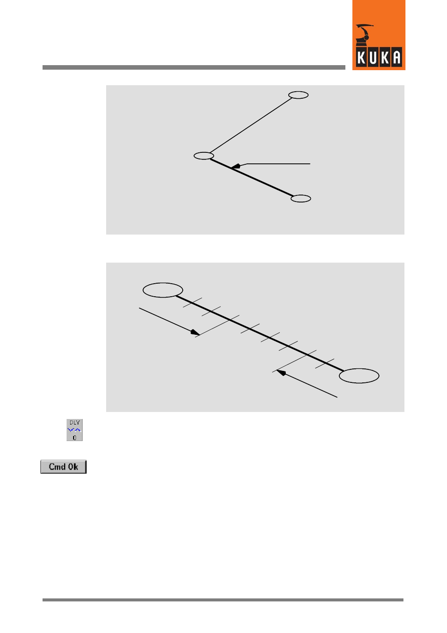
Motion block
1
The gripper function
is executed along
this line
End point
End point
Motion block
2
The parameters START, END and Delay are used to define the point at which the gripper
function is executed.
START
END
Delay
positive
Delay
negative
Then move the cursor to the box “Delay”. You can enter a value here, using the numeric
keypad, or change the default value by increments of 1 ms using the status key (at the
bottom, to the right of the display).
Then press the softkey “Cmd Ok”. The gripper interrogation function is now fully programmed
and saved.
KUKA.Gripper-- and SpotTech 2.3
20 von 56
KUKA.Gripper&SpotTech2.3 07.06.00 en
4
SpotTech
4.1
Basic SpotTech user functions
Once the technology package has been correctly installed, additional commands are
available in the SpotTech package for spot welding applications.
4.1.1
Range of commands
An initialization command and two program commands, which are used to control the
welding equipment, are basically available for spot welding. These are:
G
INI
This initialization command is automatically entered at the beginning of each new
program that is to be created (skeleton program). This sets the basic parameters for the
robot and the application program and initializes the welding and motion commands and
approximate positioning.
G
SPOT
The command “SPOT” controls the robot motion to a weld spot, and the welding process.
The opening and closing of the welding gun retract stroke after the welding process can
also be programmed by means of this command.
Collision detection can also deactivated here.
G
RETRACT
The command “RETRACT” controls the robot motion to any point, and the opening and
closing of the welding gun retract stroke after reaching the end point. This function is
required, for example, if access to weld spots or auxiliary points with the retract stroke
of the welding gun fully open or closed is impeded by obstructing contours.
Collision detection can also deactivated here.
Motions that do not include a welding operation and do not change the state of the welding
gun retract stroke or which are used for reorientating the welding gun are programmed by
means of a command belonging to the group “Motion”.
4.1.2
The functions SPOT and RETRACT
The SpotTech basic functions “SPOT” and “RETRACT” are shown in the following sketch.
Welding gun
Component
R
etr
ac
ts
tr
ok
e
Wo
rk
in
g
st
ro
ke
Retract stroke open
“RETR OPN”
Retract stroke closed
“RETR CLO”
Welding process
“SPOT”
21 von 56
KUKA.Gripper&SpotTech2.3 07.06.00 en
4.2
Programming and operation
This section describes how to create spot welding programs and how to program welding
and motion commands. It also contains information on everything that has to be taken into
account when setting individual parameters.
SpotTech has a universal basic structure and each of the programming possibilities given
here is dependent on the welding equipment and user--specific subprograms that are used.
4.2.1
General information on programming
4.2.1.1 Variables in input boxes of the inline forms
The inline forms contain a series of input boxes, whose designations are freely selectable.
This applies to the boxes
P1 ...
Designation of the end point
PDAT1 ..., CPDAT1 ...
Designation of the “Movement parameters” data set
SDAT1 ...
Designation of the “Weld parameters” data set
The following must always be observed:
-- The designation can consist of letters and numbers. Special characters apart from the
underscore “_” cannot be used.
-- The first character of a designation must always be a letter.
-- The designation is entered unchanged as a pure character string into all of the
subsequent program lines.
-- If the last character is a number, the value of this number is automatically incremented
(n+1), e.g. “SDAT1”, “SDAT2” ... “SDATn” or “SEAM_FRONT1”, “SEAM_FRONT2”
... “SEAM_FRONT99”, in the subsequent commands.
If a number is entered at the end of the designation -- this number being incremented (n+1)
in each subsequent command -- please remember that the number of characters increases
by 1 when going from 9 to 10.
4.2.1.2 Overview of the inline forms
The following sections contain screenshots of the inline forms assigned to each of the
“SpotTech” commands, showing both the input boxes and the parameter lists that can be
opened in the status window if the cursor is moved to the appropriate box in the inline form.
The operator control elements and symbols that are used here are explained below:
If the inline form is active, the desired input box can be selected by means of the arrow keys.
The selected box is displayed in white lettering on a blue background.
The operator control elements shown below the inline form are intended to be an additional
aid to familiarize you with the possibilities of making entries in inline forms and parameter
lists. These have the meanings described below:

KUKA.Gripper-- and SpotTech 2.3
22 von 56
KUKA.Gripper&SpotTech2.3 07.06.00 en
If the cursor is positioned in the appropriate box of the inline form, the bottom right status key
can be used to alter the parameters or to select data sets that have already been defined.
It is possible to both enter and alter commands and parameters by means of the keypad (by
pressing the initial letter of the command/parameter).
This symbol indicates that a parameter list (movement or weld parameters) is assigned to
the input box in the inline form. The status window together with the appropriate parameter
list is activated when the “Window selection” key on the graphical user interface is pressed.
This softkey (which is only available when a parameter list is active in the status window) is
used to exit the status window and activate the corresponding input box in the inline form.
4.2.2
Spot welding (SPOT)
The command “SPOT” controls the robot motion to a weld spot, and the welding process.
It can also be used to control the opening and closing of the welding gun retract stroke
(RETRACT) after the welding process.
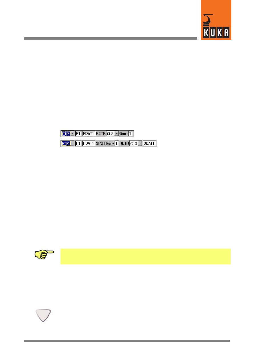
This command primarily contains the type of motion (PTP, LIN, CIRC), the designation of the
weld spot (Pn), the movement parameters (PDATn or CDATn), the weld parameters
(SDATn) and the designation of the welding gun (Gun= n) and the activation of collision
detection.
4.2.3
Types of motion
Three types of motion can be selected for the command “SPOT”: “PTP”, “LIN” and “CIRC”.
Since the robot must be exactly positioned to each weld spot, the “approximate positioning”
function is not included.
4.2.3.1 Point--to--point (PTP) motion
PTP (point--to--point) motion allows the robot to be moved to the end position at the highest
possible velocity. This motion is the most efficient. For spot welding seams, most robot
motions between the individual weld spots are generally executed as PTP motions.
However, it must be remembered that:
The path cannot be predicted exactly for PTP motions! The motion characteristics
of the robot with greater distances between points and near obstacles should
therefore be checked in a test run.
4.2.3.2 Motion along a straight line (LIN)
LIN (linear) motions are used whenever the robot has to follow an exact path to the end point.
4.2.3.3 Motion along a circular path (CIRC)
In the case of CIRC motions, the welding gun is moved along a circular path. This type of
motion is selected whenever the gun cannot be positioned to the end point using a linear
motion.
4.2.3.4 Activating/deactivating collision detection
Irrespective of the type of motion, collision detection can be activated or deactivated for the
weld gun. If detection is activated, the necessary KRL program lines are integrated into the
fold block.
23 von 56
KUKA.Gripper&SpotTech2.3 07.06.00 en
4.2.4
Programming a weld spot (SPOT)
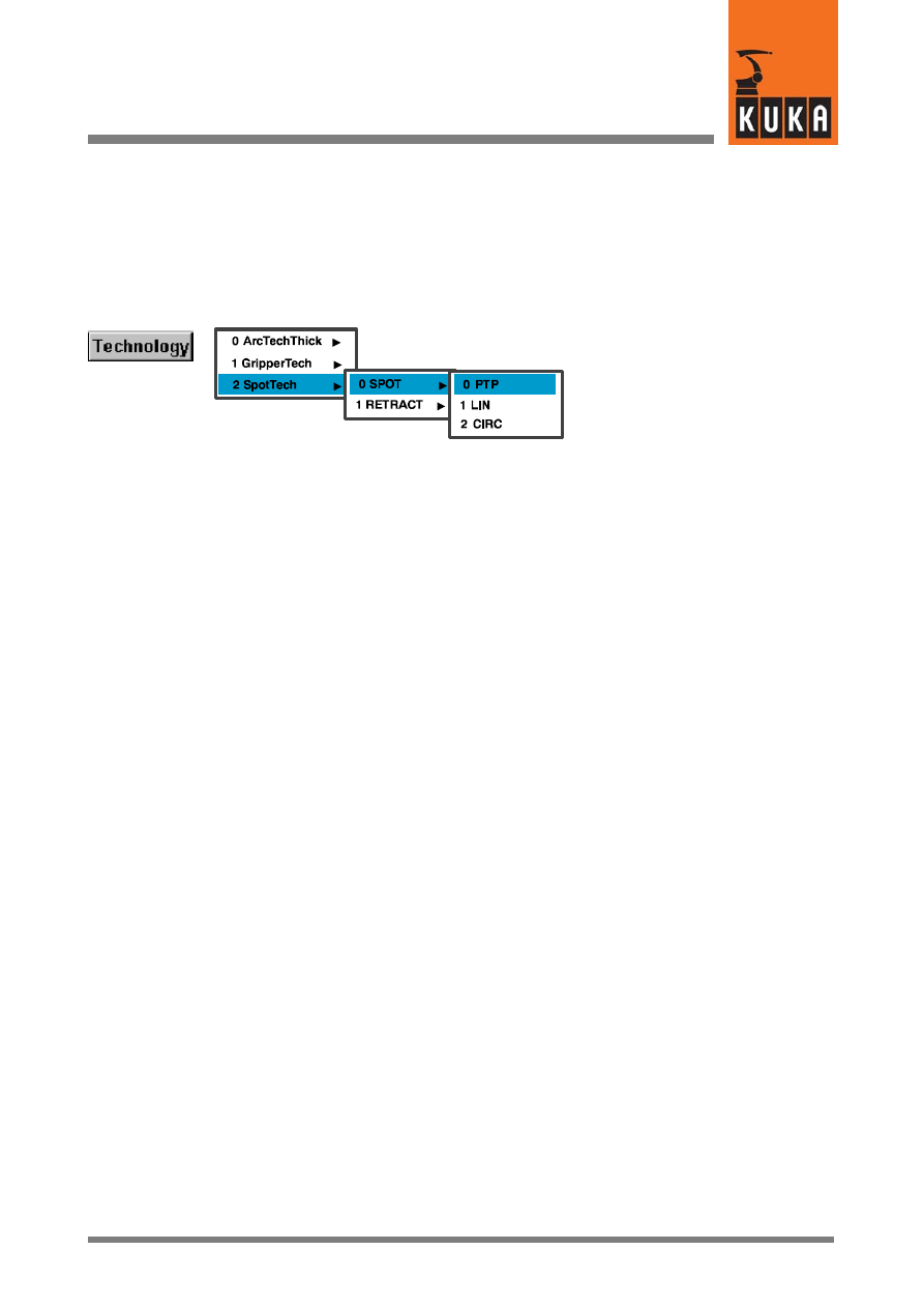
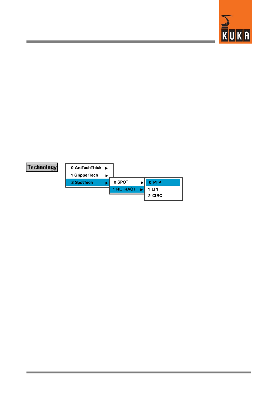
4.2.4.1 Menu
After selecting the relevant option (“SPOT Tech -- SPOT -- PTP” in this example) by means
of the menu key “Technology”, the inline form described in the next section is opened.
KUKA.Gripper-- and SpotTech 2.3
24 von 56
KUKA.Gripper&SpotTech2.3 07.06.00 en
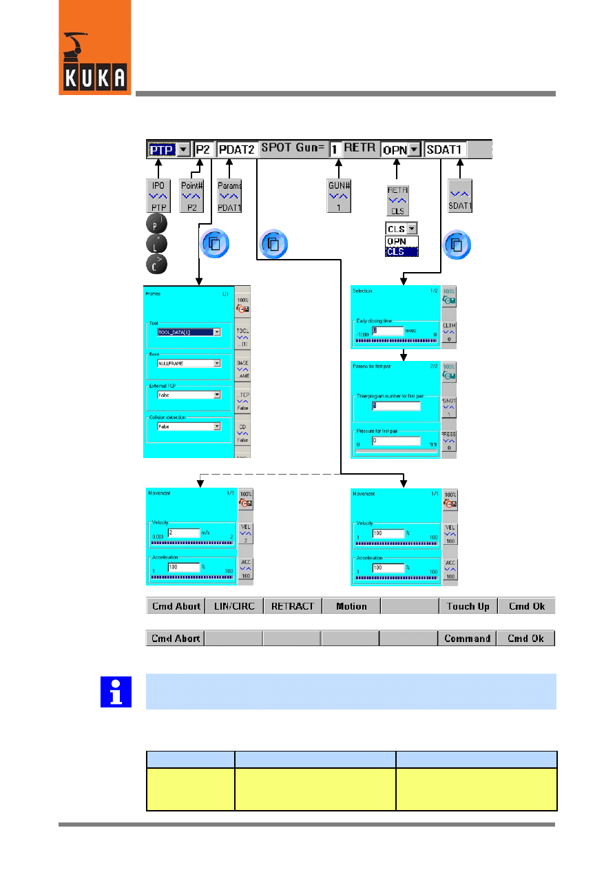
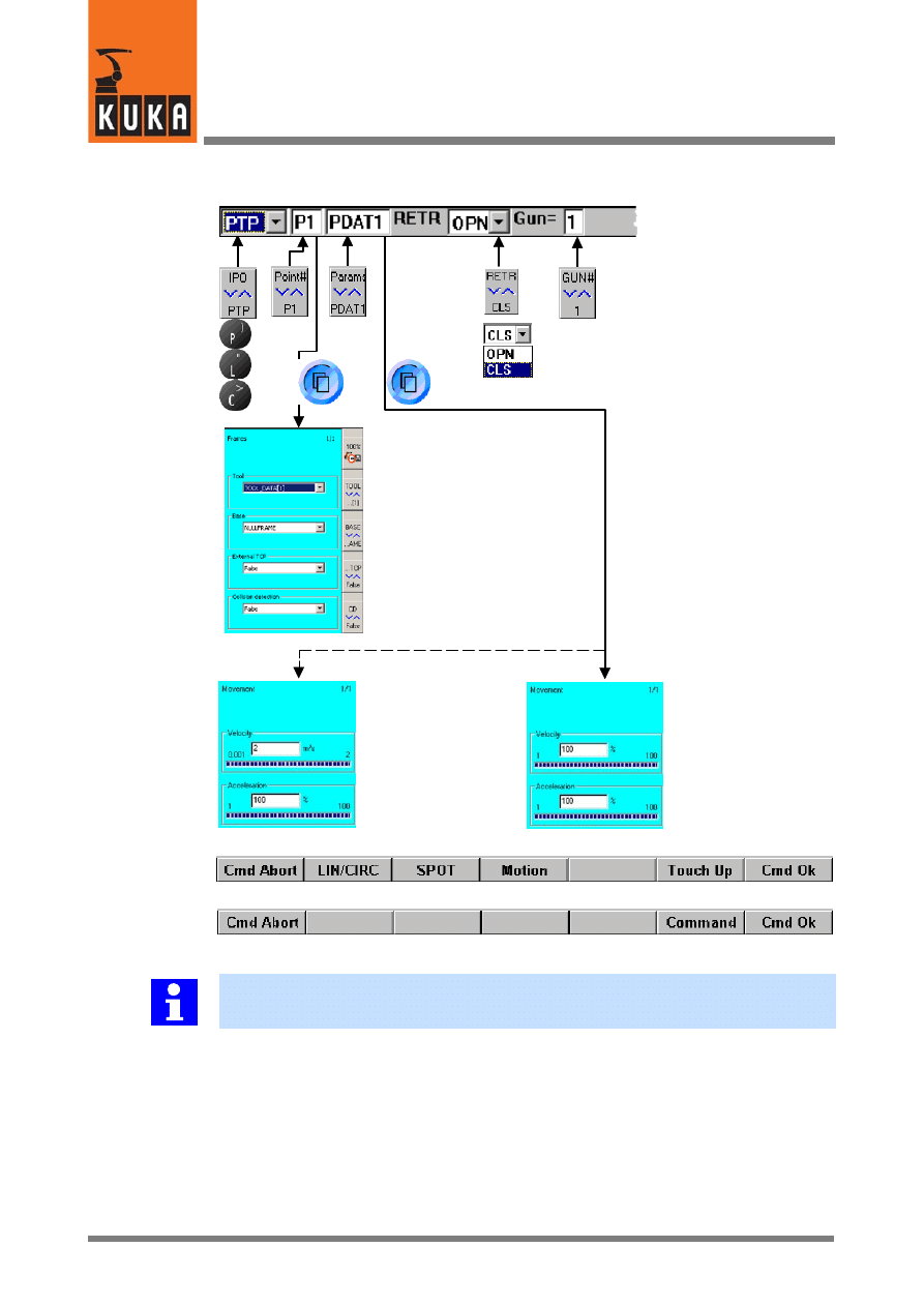
4.2.4.2 The inline form and the parameter lists for the welding command “SPOT”
Frames
Ext. TCP
“True” or “False”
LIN/CIRC
PTP
Softkey bar when the inline form is active
Softkey bar when a parameter list is active
Tool coordinate
system
Base coordinate
system
Example of a
weld parameter list
Early closing of
the welding gun
Timer program for
the 1st gun pair
Pressure for
the 1st gun pair
LIN/CIRC
motion
PTP motion
Velocity
(0.001 to 2 m/s)
Acceleration
(1 to 100 %)
Velocity
(1 to 100 %)
Acceleration
(1 to 100 %)
Collision detection
“True” or “False”
You can switch to the commands “RETRACT” or “Motion” and change the motion type
(PTP, LIN or CIRC) at any time during programming, until this is concluded using “Cmd Ok”.
Brief description of the input boxes of the inline form (from left to right), their functions and
their range of values where applicable:
Box
Function
Range of values, Comments
PTP
Type of motion
PTP, LIN, CIRC
Change using bottom right status
key, softkey or keypad.
25 von 56
KUKA.Gripper&SpotTech2.3 07.06.00 en
P2
Designation of the end point;
with CIRC motions, a further
input box is available for the
auxiliary point.
Freely selectable
Change the designation Pn by
using the keypad or the bottom
right status key.
PDAT2
Designation of the movement
parameters
Freely selectable (see Section
4.2.1.1).
SPOT Gun= 1
Designation of the welding gun
Select from up to 5 guns.
RETR OPN
Retract stroke after the welding
process (RETRACT)
CLO = retract stroke closed
OPN = retract stroke open
SDAT1
Designation of the weld parame-
ters
Freely selectable (see Section
4.2.1.1).
4.2.4.3 Selecting the welding gun (Gun = n)
It is possible to select from up to 5 welding guns. This is dependent on the welding equipment
that is used.
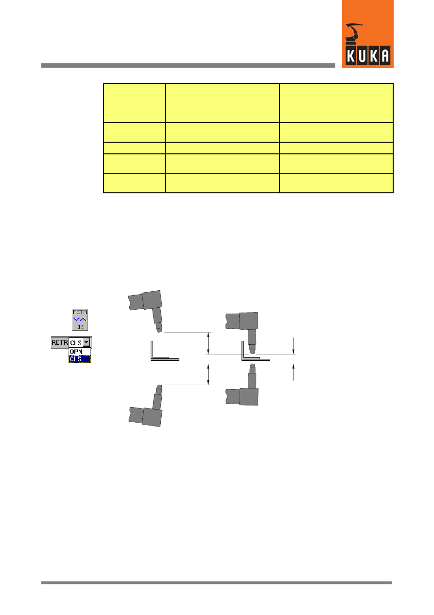
4.2.4.4 Retract stroke after the welding process (RETR OPN / CLO)
In this input box, you define whether the welding gun retract stroke is to be open or closed
after the welding process.
Welding gun
Component
R
etr
ac
ts
tr
ok
e
Wo
rk
in
g
st
ro
ke
Retract
stroke open
“RETR OPN”
Retract stroke closed
“RETR CLO”
You can switch between “Retract stroke open” (RETR OPN) and “Retract stroke closed”
(RETR CLO) by pressing the bottom right status key. This status key has a toggle function
in this instance. The pulldown menu will be opened and closed automatically after a short
time. Alternatively, the respective initial letter (“O” = OPN = open; “C” = CLO = closed) can
be entered by means of the keypad. The cursor must be positioned in the input box next to
“RETR” in this case.
4.2.4.5 Weld parameter list
Due to the universal basic structure of the spot welding technology, the parameters for the
welding data can be adapted individually to the requirements of both the user and the welding
equipment that is used.
The option of closing the welding gun early is described below on the basis of a spot welding
application.
KUKA.Gripper-- and SpotTech 2.3
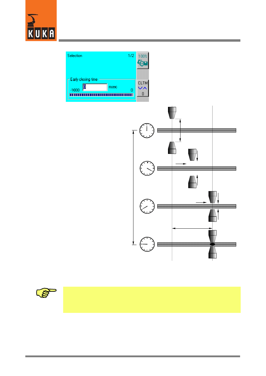
26 von 56
KUKA.Gripper&SpotTech2.3 07.06.00 en
Early closing of the welding gun
(early closing time)
-- 1000 to 0 milliseconds
Pn
Start of early
closing of gun
Weld spot
position Pn
reached
Gun closed
Ea
rly
cl
osi
ng
time
Working stroke
Early closing
distance
The point of closing the gun early (early closing time) is to optimize the time taken to execute
the spot welding process. Whilst the welding gun is still moving to the weld spot, the closing
operation is already starting. In this instance, it must be ensured that the gun is not closed
completely until just after the end position Pn is reached.
Variations in air pressure, the position of the gun and other factors may produce different
opening and closing times for the gun. The closing time of the welding gun must therefore
be checked in a test run. Closing the gun too early while the robot is still moving results in
the weld spot being incorrectly positioned and may cause the component and the tool to
be damaged!
4.2.5
Opening/closing the welding gun retract stroke (RETRACT)
The command “RETRACT” controls the robot motion to any point, and the opening and
closing of the welding gun retract stroke. This function is required, for example, if access to
weld spots or auxiliary points with the gun fully open or closed as far as the working stroke,
is impeded by obstructing contours.
27 von 56
KUKA.Gripper&SpotTech2.3 07.06.00 en
In addition to the type of motion (PTP, LIN, CIRC), the name of the end point (Pn), the
movement parameters (PDATn or CDATn) and the designation of the welding gun (Gun= n),
this command also contains an instruction specifying whether the gun retract stroke is to be
open (OPN) or closed (CLO) after the end point has been reached.
Irrespective of the type of motion, collision detection can be activated or deactivated.
4.2.5.1 Types of motion
Three types of motion can be selected for the command “RETRACT”: “PTP”, “LIN” and
“CIRC”. Approximate positioning is not possible; the robot is exactly positioned to each point.
Further details on this are given in Section 4.2.3.
4.2.5.2 Programming the retract stroke (RETRACT)
Menu (The menu items contained depend on the specific software configuration.)
After selecting the relevant option by means of the menu key “Technology” (“SPOT Tech --
RETRACT -- PTP” in this example), the inline form described in the next section is opened.
KUKA.Gripper-- and SpotTech 2.3
28 von 56
KUKA.Gripper&SpotTech2.3 07.06.00 en
The inline form and the parameter lists for the command “RETRACT”
Frames
LIN/CIRC
PTP
Tool coordinate
system
Base coordinate
system
LIN/CIRC
motion
Velocity
(0.001 to 2 m/s)
Acceleration
(1 to 100 %)
PTP motion
Velocity
(1 to 100 %)
Acceleration
(1 to 100 %)
Softkey bar when the inline form is active
Softkey bar when a parameter list is active
Ext. TCP
“True” or “False”
Collision detection
“True” or “False”
You can switch to the commands “SPOT” or “Motion” and change the motion type (PTP,
LIN or CIRC) at any time during programming, until this is concluded using “Cmd Ok”.
Brief description of the input boxes of the inline form (from left to right), their functions and
their range of values where applicable:
29 von 56
KUKA.Gripper&SpotTech2.3 07.06.00 en
Box
Function
Range of values, Comments
PTP
Type of motion
PTP, LIN, CIRC
Change using bottom right status
key, softkey or keypad
P1
Designation of the end point;
with CIRC motions, a further
input box is included for the
auxiliary point.
Freely selectable
Change the designation Pn by
using the keypad or the bottom
right status key.
PDAT1
Designation of the movement
parameters.
Freely selectable
RETR OPN
Retract stroke after reaching the
end point.
OPN = retract stroke open
CLO = retract stroke closed
SPOT Gun= 1
Designation of the welding gun
Select from up to 5 guns.
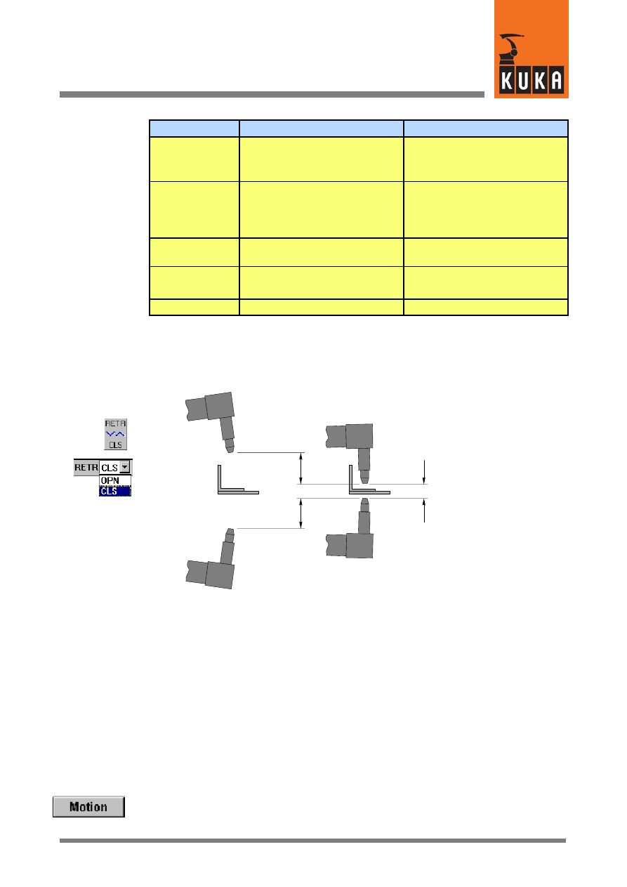
Retract stroke after reaching the end point (RETR OPN / CLO)
In this box, you define whether the welding gun retract stroke is to be open or closed after
the end point has been reached.
Welding gun
Component
R
etr
ac
ts
tr
ok
e
Wo
rk
in
g
st
ro
ke
Retract
stroke open
“RETR OPN”
Retract stroke closed
“RETR CLO”
You can switch between “Retract stroke open” (RETR OPN) and “Retract stroke closed”
(RETR CLO) by pressing the bottom right status key. This status key has a toggle function
in this instance. The pulldown menu will be opened and closed automatically after a short
time. Alternatively, the respective initial letter (“O” = OPN = open; “C” = CLO = closed) can
be entered by means of the keypad. The cursor must be positioned in the input box next to
“RETR” in this case.
4.2.6
Motion commands
Motions of the tool which do not feature a welding operation and which do not change the
welding gun retract stroke can be programmed by means of the command “Motion” from the
“Commands” menu.
A corresponding inline form is opened by means of the softkey “Motion”, with the motion type
(PTP, LIN or CIRC) that was predefined with the last command being displayed; this must
be changed, if necessary.
KUKA.Gripper-- and SpotTech 2.3
30 von 56
KUKA.Gripper&SpotTech2.3 07.06.00 en
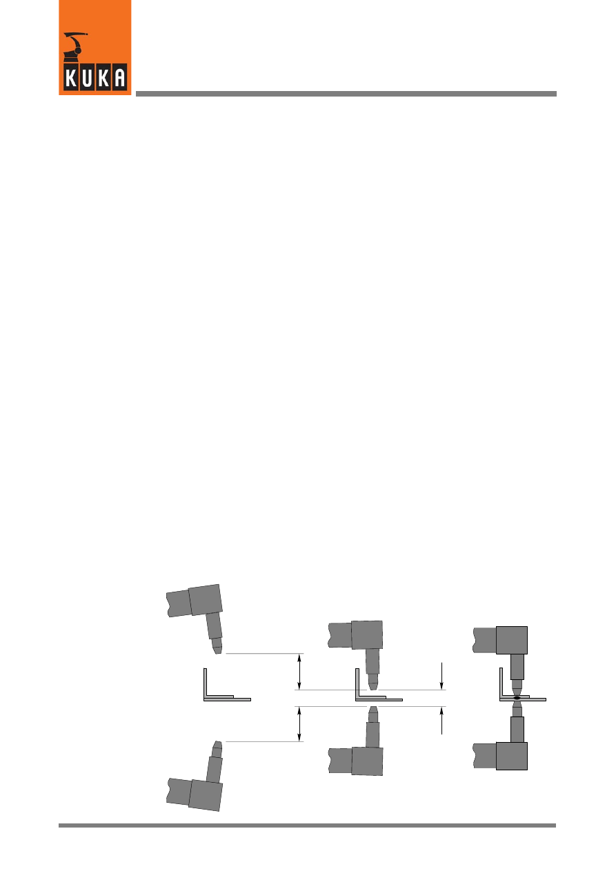
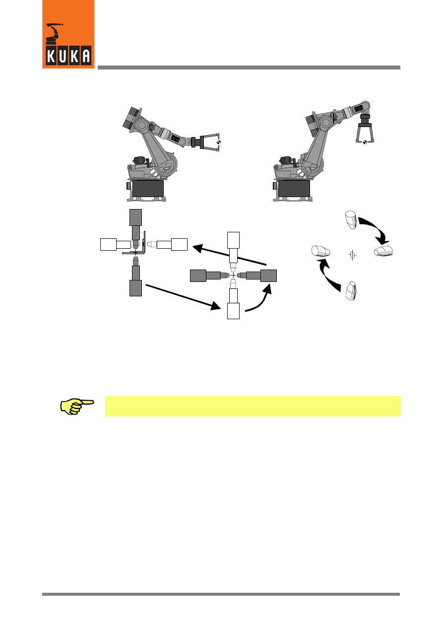
4.2.7
Reorientation of the welding gun
Pn
(P2)
Pn
(P3)
P4
P1
P3
P2
Reorientation of the
welding gun by 90°
If the spot welding plane changes -- as shown in the sketch above -- the welding gun must
be reorientated. To do so, the gun must first be moved into a position (P2) where there is no
risk of it colliding with the component or with other obstructing contours during reorientation.
The reorientation (point in space P2 to P3) is carried out using the command “Motion -- LIN”
or -- if the gun retract stroke (RETRACT) is to be changed during the same operation -- “SPOT
Tech” -- “RETRACT” -- “LIN” (see Section 4.2.5). The gun can subsequently be positioned
to the next weld spot (P4).
Depending on the position of the robot axes, it may also be possible to select a PTP motion.
As PTP motions cannot be predicted exactly, a test run should be carried out.
31 von 56
KUKA.Gripper&SpotTech2.3 07.06.00 en
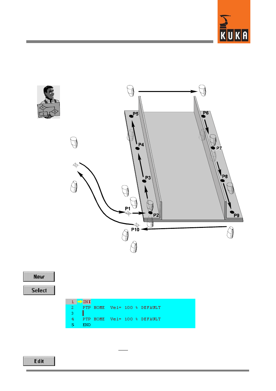
4.3
Program example
In this section, the use of the basic commands of the spot welding technology will be
described step by step on the basis of a simple program example. The assembly shown
below, consisting of three individual parts, is to be fabricated by means of spot welding.
Home
position
4.3.1
Creating a new program
To create a new program, press the softkey “New” and enter a program name (e.g. “Test”)
in the input box.
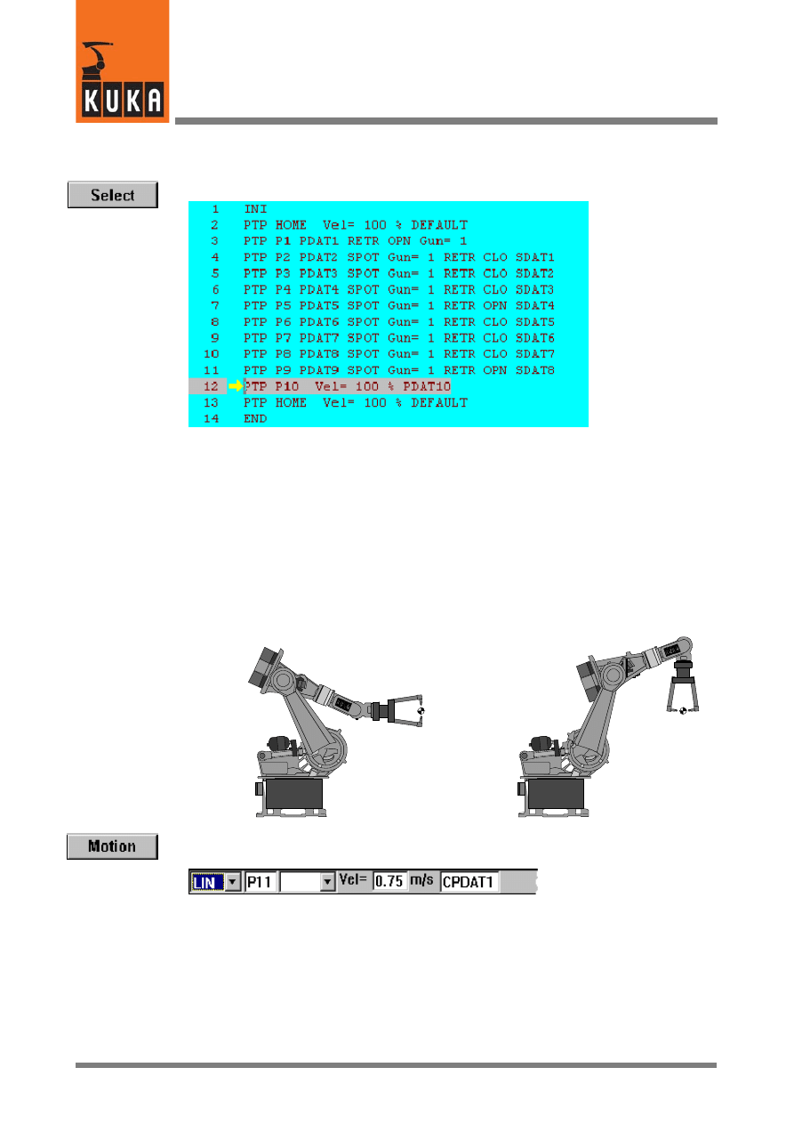
Now press the softkey “Select”. The following skeleton program is displayed in the program-
ming window:
Pay attention to the position of the edit cursor. The following program line created by you will
be inserted as a new line after the cursor.
Alternatively, you can program in edit mode by means of the softkey “Edit”. The syntax will
not be checked, however.
KUKA.Gripper-- and SpotTech 2.3
32 von 56
KUKA.Gripper&SpotTech2.3 07.06.00 en
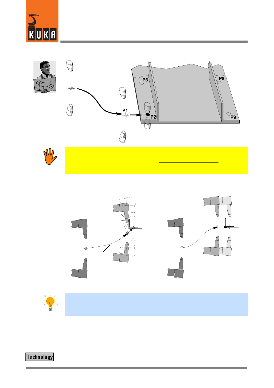
The first weld spot
Home
position
When moving the welding gun from the home position to the first weld spot, it must be
ensured that no obstructing contours (e.g. those of the component) can cause a collision.
For example, the path of the PTP motion cannot be exactly predicted! The motion
characteristics of the robot near obstacles should therefore always be checked in a test
run.
The diagram given below shows a collision situation on the left. As can be seen in the
situation on the right, you can ensure that the welding gun is positioned safely to the first weld
spot (P2) by inserting an additional point in space (P1).
Home
position
Home
position
PTP
motion
Risk of a colli-
sion with the
component!
End
position
Positioning the welding gun
directly to the end point
Component
Component
Point in space P1
1st weld
spot P2
Inserting an additional point
in space
If the motion between the point in space P1 and the first weld spot (P2) is executed as a
PTP motion, the distance between these two points should not be too great. The robot can
use approximate positioning for moving from the home position to P2 via P1 because exact
positioning is not required until the welding gun moves to the position of the weld spot.
Moving from the home position to the point in space P1 -- “RETRACT”
The welding gun is moved from the home position to the point in space P1 by means of a
PTP motion. During the same operation, you ensure that the retract stroke is open after the
point has been reached.
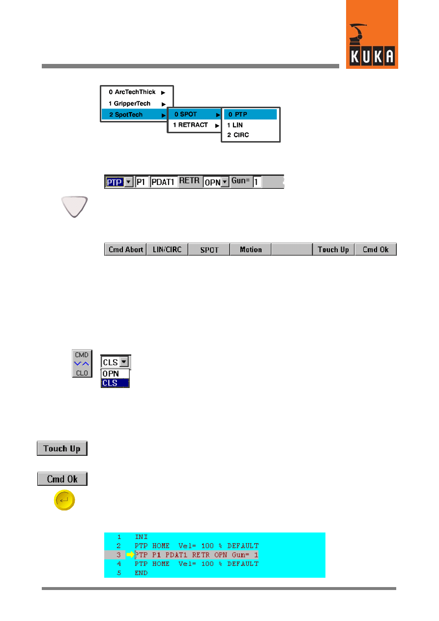
Press the menu key “Technology” and select the options shown below (menu items in white
lettering on a blue background):
33 von 56
KUKA.Gripper&SpotTech2.3 07.06.00 en
After selecting the command “SPOT Tech -- RETRACT -- PTP”, the following inline form is
opened on the screen:
If the programming window is active, the input boxes can be selected by means of the arrow
keys. The selected box appears in white lettering on a blue background.
At the same time that the inline form given above is opened, the assignment of the softkey
bar changes to that shown below:
You can also correct your original selection (“SPOT”, “Motion” and type of motion) by means
of this softkey. The inline form changes accordingly when a selection is made. The command
can be aborted by means of the softkey “Cmd Abort” or the ESC key. This will close the inline
form.
The welding gun retract stroke must be open after the point in space P1 has been reached.
This is set in the input box “RETR”. In the example given above, “OPN” (open) is already
entered; otherwise, “CLO” (closed) appears here.
To change the setting, move the cursor to the input box “RETR”. You can
switch between “RETR CLO” and “RETR OPN” by means of the bottom right
status key. This status key has a toggle function. Alternatively, the letter “C”
(=closed) or “O” (=open) can be entered by means of the keypad. In this case,
enter “O”.
For the purpose of positioning the welding gun, move it to the position P1 by means of the
Space Mouse or the traversing keys. Information on controlling motions of the robot manually
can be found in the chapter [Manual traversing of the robot].
You can now press the softkey “Touch Up”. In this case, press the softkey “Yes” to confirm
the query “Touchup (Y/N)?” that is displayed in the message window. Alternatively, press the
softkey “Cmd Ok” or the Enter key. The current robot coordinates are automatically saved.
The command is ended by pressing the softkey “Cmd Ok” or the Enter key. If the point P1
has not yet been touched up, the current robot coordinates are now automatically saved. The
information message “Point P1 created automatically” is displayed in the message window.
The inline form is closed and the generated program line is inserted into the program form
afterwards. The numbers of the following program lines are automatically updated.
KUKA.Gripper-- and SpotTech 2.3
34 von 56
KUKA.Gripper&SpotTech2.3 07.06.00 en
Setting the first weld spot (SPOT)
A PTP motion is used to move the welding gun from the point in space P1 to the weld spot
P2. The gun is exactly positioned to point P2 where the welding process will then be
executed. Since a sequence of further spot welds follows P2, the retract stroke can remain
closed.
Press the menu key “Technology” and select the options shown below (menu items in white
lettering on a blue background):
After selecting the command “SPOT Tech” -- “SPOT” -- “PTP”, the following inline form
appears on the display.
Alternatively, you can also press the softkey “Last Cmd”. If you had last entered a
“RETRACT” command, an inline form for the command “RETRACT” is displayed. “SPOT”
can then be called by means of the softkey “SPOT”. The same inline form is thus available.
As can be seen, the names for the end point (P2) and the data set (PDAT2) have been
adapted. A further box is also displayed: the designation of the weld parameter set (SDAT1).
The welding gun retract stroke can be left closed (“RETR CLO”) in this program example.
If the first command to be entered was “RETR OPN” (retract stroke open), this has been used
as a default setting in the input box of the new inline form.
To change the setting, move the cursor to the input box “RETR”. Press the bottom right status
key or enter the letter “C” by means of the keypad. “CLO” (=closed) subsequently appears
in the input box of the inline form.
Enter the movement and weld parameters into both the inline form and the parameter lists
and move the welding gun to the desired position P2.
If your welding system has been configured appropriately, the functioning of the gun can be
checked at this point by means of the gun status keys. For information on this, see Section
4.9 and the chapter [SPOT Tech © -- Expert Programming].
After entering all of the parameters, press the softkey “Cmd Ok”. The current robot
coordinates are saved and the program form is updated accordingly.
35 von 56
KUKA.Gripper&SpotTech2.3 07.06.00 en
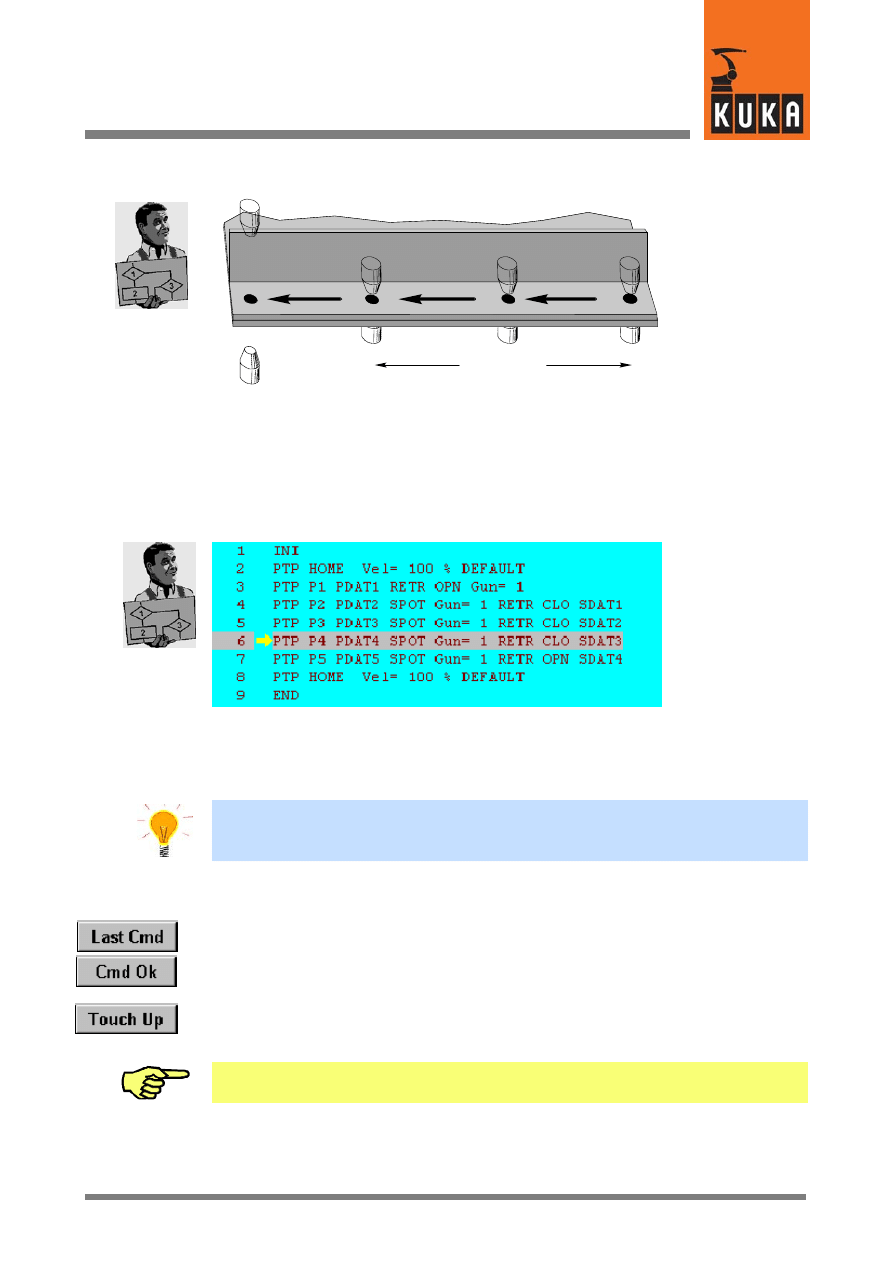
4.3.1.1 Welding the first spot sequence
P2
P3
P4
P5
RETR CLO
RETR OPN
The further points (P3 to P5) can be programmed using the procedure described in the last
section. In this case, leave the welding gun retract stroke closed (RETR CLO) for P3 and P4.
As the welding gun is to be positioned to the first weld spot (P6) of the second welding
sequence (see the sketch at the beginning of Section 4) after P5, the retract stroke must be
opened at P5. To do so, select the option “RETR OPN” when programming P5.
After all of the entries for the first spot sequence have been made, the program form appears
as follows:
As can be seen, the numeric values for the designation of the movement parameters
(PDATn) have each been increased by 1 in command lines 4 to 7. The numeric values for
the designation of the weld parameters (SDATn) have likewise been increased. The parame-
ters entered in “SDAT1” have automatically been entered in “SDAT2” .... “SDAT4”.
For spot sequences that are to be welded with the same welding tool and the same weld
parameters, programming can be simplified if each weld spot is not programmed
individually but by using the procedure described below:
G
Program the first weld spot of the sequence.
G
Determine the number of spots that are to be welded after the first spot.
G
Press the softkey “Last Cmd” and then the softkey “Cmd Ok”.
Repeat this according to the number of weld spots.
G
To save the robot coordinates, subsequently move the edit cursor (vertical line) to the
appropriate line of the program form in sequence. Position the robot manually to the
respective point, press the softkey “Touch Up” and confirm the request for confirmation
to save the coordinates. The current robot coordinates are saved for the point that is
currently selected.
With the motion type “CIRC”, the coordinates for the required auxiliary point must always
be touched up manually.

KUKA.Gripper-- and SpotTech 2.3
36 von 56
KUKA.Gripper&SpotTech2.3 07.06.00 en
4.3.1.2 Welding the second spot sequence
The second spot sequence begins at P6. A PTP motion can be used between the weld spots
P5 and P6 as the distance between them is small and the welding gun retract stroke is open.
The weld spot P6 can be programmed in the program example given above.
Now program the weld spots P7 to P9 following the description given in the previous section.
Select the option “RETR OPN” again for the last weld spot (P9) to open the welding gun
retract stroke after P9 has been welded.
4.3.1.3 Moving from the end of the spot seam to the home position
To move the welding gun back to the home position, a further point in space outside the
component is required so that a collision is safely avoided. This is P10 in this program
example, where it is assumed that there are no obstacles between P10 and the home
position.
The path between the weld spot P9 and the point in space P10 is executed as a “PTP” motion.
Press the softkey “Motion”. An inline form is opened:
After entering the parameters, press the key “Cmd Ok”.
Alternatively, this motion can also be programmed by means of the command “SPOT Tech”
-- “RETRACT” -- “PTP”.
The motion from P10 to the home position (“PTP -- HOME”) is already included in the
skeleton program. Programming of this program example is thus completed.
37 von 57
KUKA.Gripper&SpotTech2.3 07.06.00 en
4.4
Altering existing programs
It is possible to alter commands and/or parameters and to delete command lines in an
existing program at any time. Two examples are given below.
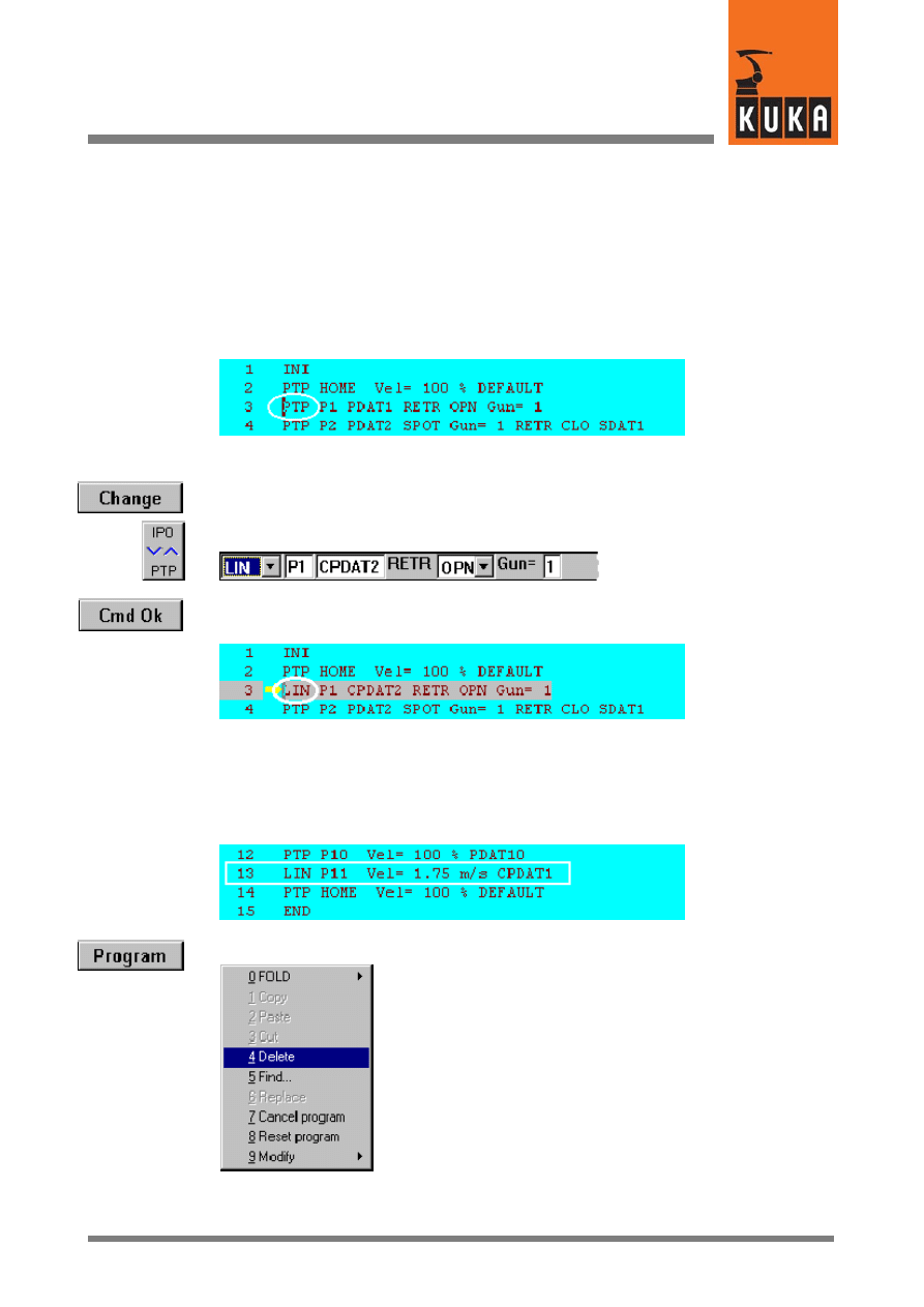
4.4.1
Altering command lines
The procedure for altering command lines is demonstrated below by using a different type
of motion for the command “SPOT -- RETRACT” to the point in space P1 to that used in the
above program example. The parameter “PTP” for P1 is to be changed to “LIN”.
Move the edit cursor to line 3 by means of the arrow keys.
Press the softkey “Change”. The inline form for this command line is opened. Move the cursor
to the first input box on the left.
Press the bottom right status key until “LIN” appears in the input box.
Then press the softkey “Cmd Ok”. The inline form is closed and the program form is updated
accordingly.
4.4.2
Deleting command lines
The motion command that appears in line 13 of the program form given below (P11) is to be
deleted. To do so, move the edit cursor to line 13.
Press the menu key “Program”
and select “Delete” by means of the arrow key. Then press the Enter key. The key “1” in the
numeric keypad can also be pressed (do not press Enter).
KUKA.Gripper-- and SpotTech 2.3
38 von 57
KUKA.Gripper&SpotTech2.3 07.06.00 en
Line 13 has been deleted and the original line 14 is now line 13.
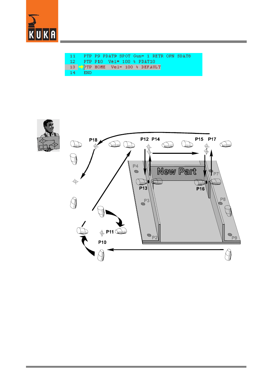
4.4.3
Adding commands to an existing program
The procedure for adding commands to an existing program is given below. A further part
is added to the welded assembly described in Section 4.3:
Home
position
Reorientation of
the welding gun
by 90°
The new part is welded to the two brackets by means of two spots (P13 and P16 in the
diagram). As the welding gun has to be reorientated by 90° to weld these two spots in relation
to welding the spot sequences P2 to P5 and P6 to P9, it is advisable to weld them before
welding spot sequences P2 to P9.
In this example, these two spots are to be welded after weld spot P9. This requires the follow-
ing changes to be made to the program:
-- Alter the command “Motion” (P10)
-- Insert the command “Motion” (P11) to reorientate the welding gun
-- Insert the command “Motion” (P12)
-- Insert the command “SPOT -- SPOT” (P13)
-- Insert the command “Motion” (P14)
-- Insert the command “Motion” (P15)
-- Insert the command “SPOT -- SPOT” (P16)
-- Insert the command “RETRACT” (P17)

39 von 57
KUKA.Gripper&SpotTech2.3 07.06.00 en
-- Insert the command “Motion” (P18)
KUKA.Gripper-- and SpotTech 2.3
40 von 57
KUKA.Gripper&SpotTech2.3 07.06.00 en
4.4.3.1 Description of the alteration
Open the program form from the previous section.
4.4.3.2 Changing the position of the welding gun (point in space P10)
Move the edit cursor to line 12. Position the welding gun to the point in space P10. When
doing so, ensure that it cannot collide with the component or with other obstructing contours
during the following reorientation to P11. Press the softkey “Touch Up” to save the new robot
coordinates.
4.4.3.3 Reorientation of the welding gun -- inserting the command “Motion” (P11)
P10
P11
Ensure that the edit cursor is positioned in line 12 (P10). An inline form is opened by pressing
the softkey “Motion”.
Select the motion type “LIN”. Use the traversing keys or the Space Mouse to align the welding
gun accordingly (rotate by 90°). Save the current robot coordinates (Touch Up) and press
the softkey “Cmd Ok” after entering all the parameters.
41 von 57
KUKA.Gripper&SpotTech2.3 07.06.00 en
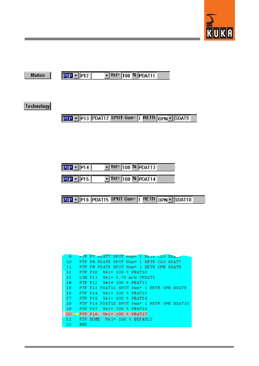
4.4.3.4 Moving to the point in space P12 -- inserting the command “Motion”
Now insert the command “Motion -- PTP” to move the welding gun to the point in space P12,
which is located above the weld spot P13.
4.4.3.5 Welding spot P13 -- inserting the command “SPOT”
Select “SPOT Tech” -- “SPOT” -- “PTP”. Select the option “RETR OPN” in the inline form,
enter the required parameters and close the inline form with “Cmd Ok”.
4.4.3.6 Moving to the weld spot P16 and welding
The welding gun is moved to the weld spot P16 via the points in space P14 and P15. Two
PTP motions are programmed from P13 to P14 and from P14 to P15. The appropriate inline
forms are shown below:
This is followed by the welding command “SPOT Tech” -- “SPOT” -- “PTP”:
4.4.3.7 Moving to the home position
The welding gun is moved to the home position via the points in space P17 and P18. The
motions from P16 to P17 and from P17 to P18 are to be programmed. The motion to “PTP
-- HOME” is already included in the skeleton program.
Alteration of the program is now completed.
The altered line 12 (P10) and the new lines 13 to 20 (P11 to P18) are indicated by the white
line on the left in the diagram.
KUKA.Gripper-- and SpotTech 2.3
42 von 57
KUKA.Gripper&SpotTech2.3 07.06.00 en
4.5
SpotTech configuration
Configuration of the SpotTech software package is only possible in expert mode.
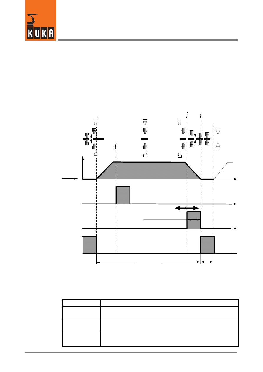
4.5.1
Program sequence
The following diagram shows the basic sequence of a spot welding program between two
weld spots.
P
(n--1)
P
n
t
t
t
t
Weld spot
Trigger
PRESPOT
Trigger
SPOT
Weld spot
or starting point
Robot
motion
ADVSPOT
PRESPOT
SPOT
Weld
duration
(weld start --
weld complete)
Gun closing time
Weld complete
WLD_CMP
Communication with the
welding controller
(e.g.
setting program parameters)
Weld start
WLD_STRT
ADVSPOT
Time t
Working
stroke open
Retract open
(if programmed)
RETRACT
The usable functions depend on the type of welding gun used as well as its controller. The
individual functions:
Name
Description
Retract stroke
RETRACT
Retract stroke of the welding gun. Completely opens the gun, for
example, to approach weld spots over component edges.
Working stroke
Working stroke of the welding gun. The working stroke is generally
sufficient for spot sequences along even surfaces.
ADVSPOT
Advance communication with the welding controller (during gun
movement) so that all required weld data are available when the end
point is reached.
43 von 57
KUKA.Gripper&SpotTech2.3 07.06.00 en
PRESPOT
Early closing of the gun; programmable in the parameter list “Selec-
tion”. The closing operation already starts while the welding gun is
still moving to the weld spot.
SPOT
The actual welding process, initiated with the “Weld start” command
(WLD_STRT) to the welding periphery until the arrival of the “Weld
complete” signal (WLD_CMP).
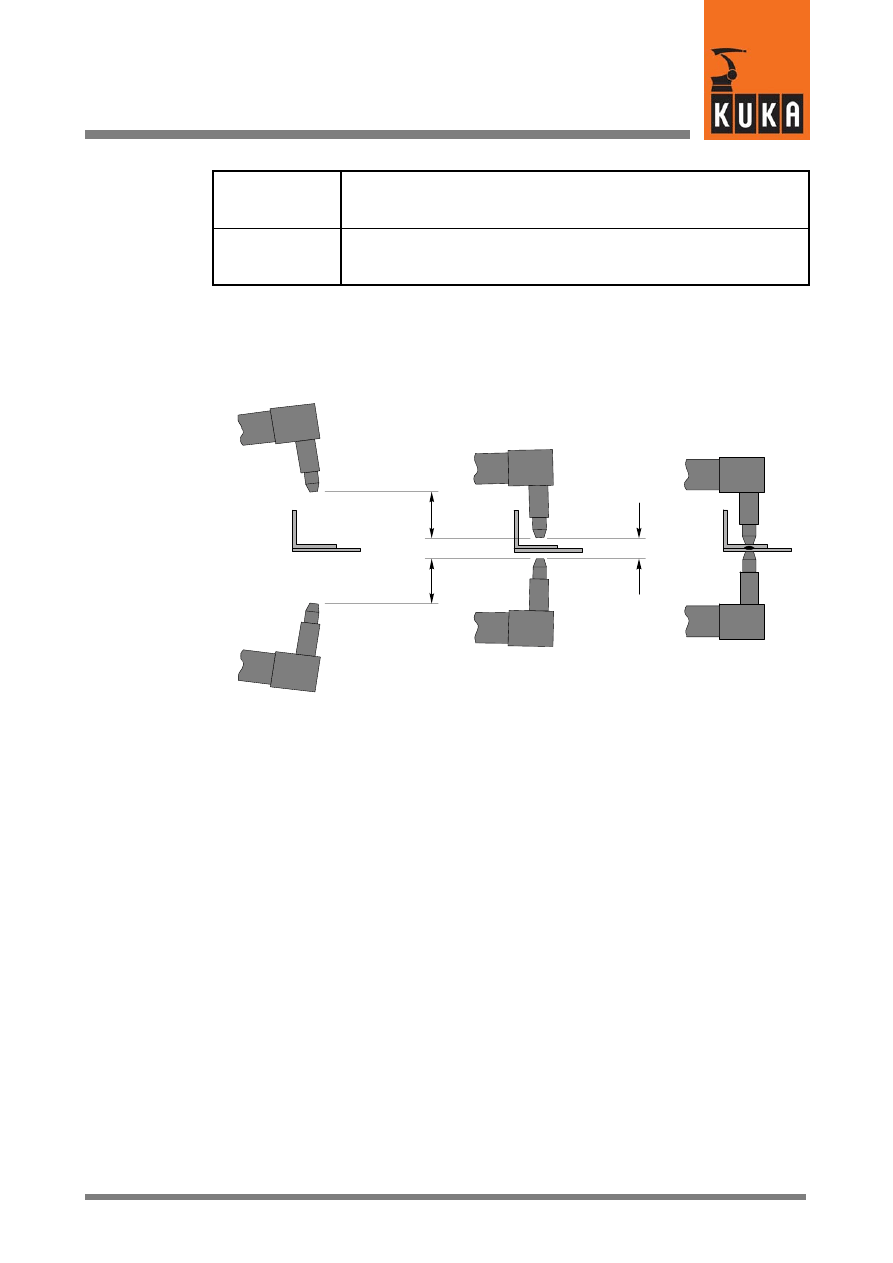
4.5.2
Retract stroke (RETRACT) and working stroke (SPOT)
The basic SpotTech functions “SPOT” and “RETRACT” are shown schematically in the
following sketch.
R
etr
ac
ts
tr
ok
e
Welding gun
Component
Wo
rk
in
g
st
ro
ke
Retract stroke open
“RETR OPN”
Retract stroke closed
“RETR CLO”
Working stroke closed
“SPOT”
4.5.3
Early closing of the gun (PRESPOT)
The “PRESPOT” function allows the gun to close while the welding gun is moving to the end
point.
KUKA.Gripper-- and SpotTech 2.3
44 von 57
KUKA.Gripper&SpotTech2.3 07.06.00 en
Weld spot
position Pn
reached
Welding gun
closed
Early closing
distance
Working stroke
Pn
Ea
rly
cl
osi
ng
time
Trigger for early gun
closing (PRESPOT)
TRIGGER WHEN DISTANCE=1
DELAY=SSDAT1.CLO_TM DO
USERSPOT(#PRESPOT,S_ACT)
PRIO= -1
Trigger for weld start
TRIGGER WHEN DISTANCE=1
DELAY=0.0 DO USERSPOT
(#SPOT,S_ACT) PRIO= -1
The point of closing the gun early (PRESPOT) is to optimize the time taken to execute the
spot welding process. The closing operation already starts while the welding gun is still
moving towards the weld spot. In this instance, it must be ensured that the gun is not closed
completely until just after the end position Pn is reached.
Variations in air pressure, the orientation of the gun and other factors may produce different
gun opening and closing times. The closing time of the welding gun must therefore be
checked in a test run. Closing the gun too early while the robot is still moving results in the
weld spot being incorrectly positioned and may cause the component and the tool to be
damaged!
45 von 58
KUKA.Gripper&SpotTech2.3 07.06.00 en
4.6
Components of the SpotTech package
4.6.1
Program structure
The interface to the welding controller is implemented in the form of a configurable
“handshake”. The settings and assignments of the physical inputs and outputs are defined
in the file “$CONFIG.DAT”.
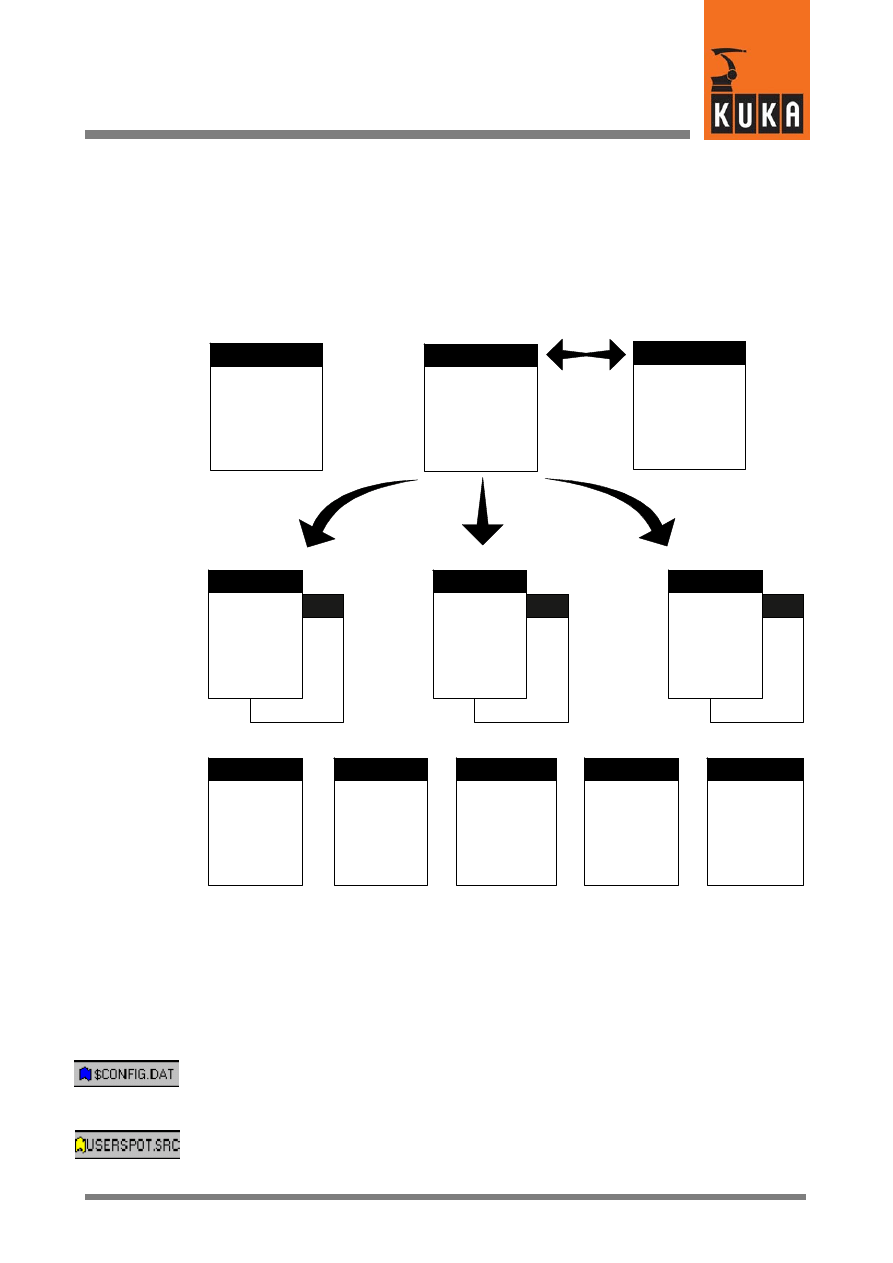
In the following block diagram the program structure of the KR C1 robot controller is shown
in the “Spot welding robot” configuration.
BAS(...)
H50(...)
USERSPOT
*.SRC
*.DAT
H50.SRC
BAS.SRC
P00.SRC
CELL.SRC
SPS.SUB
BAS(...)
H50(...)
USERSPOT
*.SRC
*.DAT
BAS(...)
H50(...)
USERSPOT
*.SRC
*.DAT
. . .
DEF SPS()
CWRITE (..”.RUN
/R1/CELL()”)
LOOP
...
ENDLOOP
USERSPOT.SRC
IR_STOPM.SRC
$CONFIG.DAT
USERSPOT
PACKAGE
Technology--
specific
organization
program
Part 1
Part 2
Part n
Functions
for gripper
control
Functions
for robot
motion
Functions
for spot
welding
Functions
for
Automatic
External
Routines for
handling
faults
KR C1 program structure
4.6.2
SPOT Tech--specific files
The following files, which are included in the “SPOT Tech” package, are required for
executing spot welding applications. You will always see the symbols shown on the left with
the file names throughout this document whenever the corresponding file or parts of it are
described.
$CONFIG.DAT
Contains data specific to SPOT Tech within the Fold
“USERSPOT”.
USERSPOT.SRC
This file is supplied as a skeleton program. This is where you enter
data for your own spot welding programs, e.g. for initializing, for
RETRACT, ADVSPOT, SPOT, etc.

KUKA.Gripper-- and SpotTech 2.3
46 von 58
KUKA.Gripper&SpotTech2.3 07.06.00 en

47 von 58
KUKA.Gripper&SpotTech2.3 07.06.00 en
4.7
Adaptation to the periphery, configurable options
This section describes the SpotTech peripheral interfaces with an example illustrating the
assignment of the digital outputs and inputs. The Fold “USERSPOT” contained in the file
“$CONFIG.DAT” as well as the file “USERSPOT.SRC” are described.
4.7.1
FOLD “SPOT” in the file “$CONFIG.DAT”
The Fold “SPOT” from the file “$CONFIG.DAT” is shown below.
;FOLD SPOT GLOBALS;
;==================================
; Structures:
;==================================
ENUM S_COMMAND SPOT,RETR,PRESPOT,INIT,ADVSPOT
Branch
“SWITCH CMD”
in file
“USERSPOT.SRC”C”
ENUM S_PAIR_SLCT FIRST,SECOND,BOTH
Gun--specific
parameters
STRUC SPOT_SUGG_T CHAR GUN[24],RETR_CMD[24],CHOISE[24],CLO_TM[24],
PGNO1[24],PRESS1[24],PGNO2[24],PRESS2[24],SPOT_PARAMS[24]
STRUC SPOT_TYPE INT GUN,S_PAIR_SLCT PAIR,COMMAND RETR,INT CLO_TM,
INT PGNO1,REAL PRESS1,INT PGNO2,REAL PRESS2
;==============================
; External declarations:
;==============================
EXT
USERSPOT (S_COMMAND
:IN,SPOT_TYPE
:IN )
;==============================
; Variables:
;==============================
DECL SPOT_TYPE SDEFAULT={GUN 1,PAIR
Default data set
#FIRST,RETR #OPN,CLO_TM 0,PGNO1 1,
for SPOT
PRESS1 0.0,PGNO2 0,PRESS2 0.0}
DECL SPOT_TYPE S_ACT
Global variables
DECL INT S_ACT_DELAY
that are used in
DECL BOOL S_READY
the robot program.
INT BOSCHCMD_OK=534
INT BOSCHSTAT_OK=528
;==============================
; all for Bosch-Serial-Interface
;==============================
EXT
BOSCH (INT
:IN,INT
:IN,INT
:OUT )
; BOSCH-OUTWORD 1 (513-528) param
SIGNAL BOSCHPAR $OUT[513]
TO $OUT[528]
; BOSCH-OUTWORD 2 (529-544) command
SIGNAL BOSCHCMD $OUT[529]
TO $OUT[533]
; BOSCH-INWORD 1 (513-528) status+validbit
SIGNAL BOSCHSTAT $IN[513]
TO $IN[527]
;ENDFOLD
If adaptation to the peripheral hardware used is required, please consult the corresponding
documentation.

KUKA.Gripper-- and SpotTech 2.3
48 von 58
KUKA.Gripper&SpotTech2.3 07.06.00 en
4.7.2
The user--specific program “USERSPOT.SRC”
The skeleton program “USERSPOT.SRC” provided in the SpotTech technology package
serves as the framework for applications individually tailored to the welding equipment being
used. In the following sections, you will find examples of the configuration options available.
&COMMENT USERSPOT package
DEF
USERSPOT (CMD :IN,S :IN )
;********************************
; USERSPOT - Package KR C1
; R2.2.x
; Date: 23.03.98
;
;********************************
DECL S_COMMAND CMD
DECL SPOT_TYPE S
SWITCH
CMD
CASE #INIT
Initialization (contained in INI FOLD)
INIT ( )
CASE #ADVSPOT
Call during advance run
ADVSPOT (CMD,S )
CASE #PRESPOT
Triggering of early closing of
PRESPOT (CMD,S )
the welding gun
CASE #SPOT
Triggering “Weld start” at
SPOT (CMD,S )
weld spot position
S_READY=TRUE
Enable for further program execution
CASE #RETR
Gun retract stroke (RETRACT)
RETRACT (CMD,S )
S_READY=TRUE
ENDSWITCH
END ; END OF MAIN
;*****************************
DEF
ADVSPOT (CMD :IN,S :IN )
User data for “ADVSPOT”
DECL S_COMMAND CMD
DECL SPOT_TYPE S
END ;(ADVSPOT)
;*****************************
DEF
PRESPOT (CMD :IN,S :IN )
User data for “PRESPOT”
DECL S_COMMAND CMD
DECL SPOT_TYPE S
END ;(PRESPOT)
;*****************************
DEF
SPOT (CMD :IN,S :IN )
User data for “SPOT”
DECL S_COMMAND CMD
DECL SPOT_TYPE S
END ;(SPOT)
;*****************************
DEF
RETRACT (CMD :IN,S :IN )
User data for “RETRACT”
DECL S_COMMAND CMD
DECL SPOT_TYPE S
END ;(RETR)
;*****************************
DEF
INIT ( )
User data for “INIT”
END ;(INIT)
49 von 58
KUKA.Gripper&SpotTech2.3 07.06.00 en
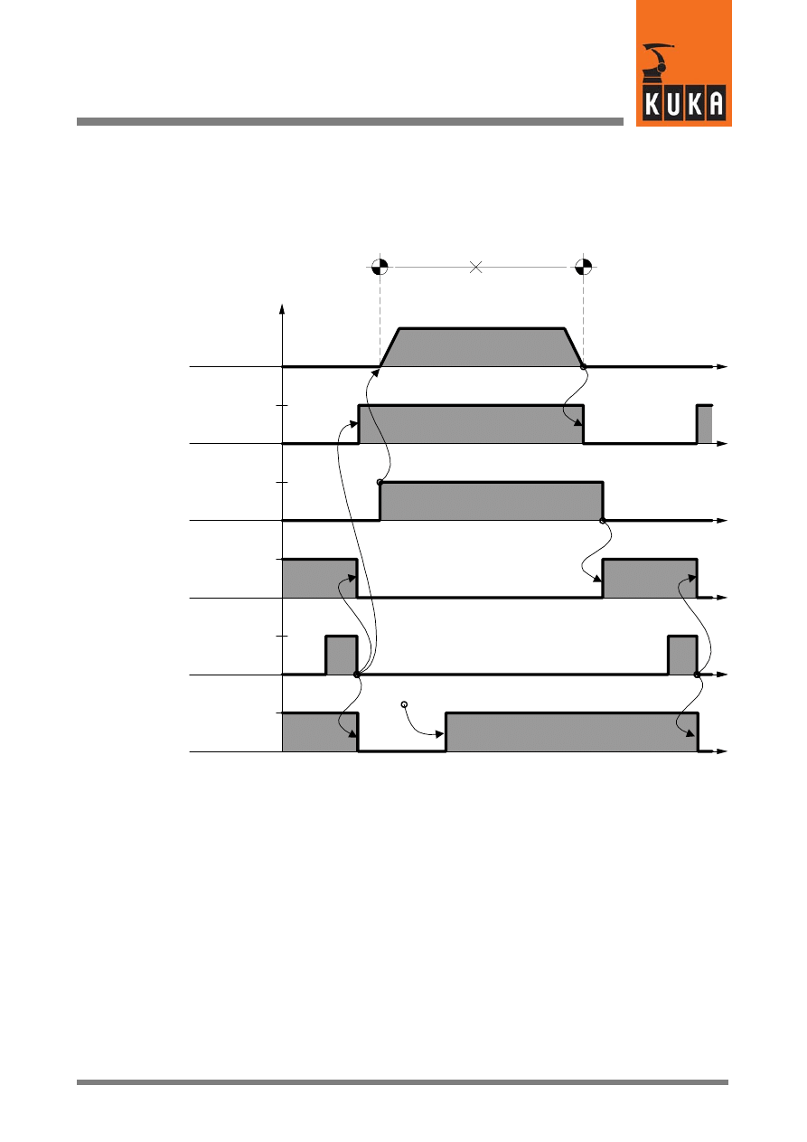
4.7.2.1 Schematic sequence diagram for SPOT (without RETRACT)
The following diagram shows the basic program sequence of the command “SPOT”. The
options “PRESPOT” (early closing of the gun) and “RETRACT” (open/close retract stroke
of the gun) are not shown.
Weld parameter
designation
0
t
t
t
t
t
t
Robot
motion
GUN_WRK
Working stroke
activation
(output)
WRK_STAT
Working stroke
status
(input)
WLD_STRT
Weld start
(output)
WLD_CMP
Weld
complete
(input)
PNUM
Program
number
(output)
OPEN
CLOSE
OPEN
CLOSE
TRUE
FALSE
TRUE
FALSE
S01
S02
(Auxiliary point)
ADVSPOT
S.PGN01
After welding the spot “S01” the weld complete signal (WLD_CMP=TRUE) triggers, with its
falling edge (WLD_CMP=FALSE), the instruction for opening the working stroke of the
welding gun (GUN_WRK=G_OPN). At the same time the weld start signal
“WLD_STRT=FALSE” as well as the program number “PNUM=0” are set.
The robot controller now waits for the status message “WRK_STAT==G_OPN” indicating
that the working stroke of the gun is open. This signal enables robot movement to the next
weld spot.
To ensure that all the data required for welding are available at the end point (in this example
point “S02”), the welding program number, for example “PNUM=S.PGN01”, is already output
during the actual movement, provided this has been configured in the section “ADVSPOT”
of the file “USERSPOT.SRC”.
At the end point (in this example point “S02”), the control instruction is given to close the
working stroke (GUN_WRK=W_CLO). The status message from the welding controller that
the working stroke is closed (WRK_STAT=W_CLO) triggers the weld start
(WLD_STRT=TRUE).
At the conclusion of the welding process, the instruction is given once again, by means of
the falling edge of the weld complete signal (WLD_CMP=FALSE), to open the working stroke
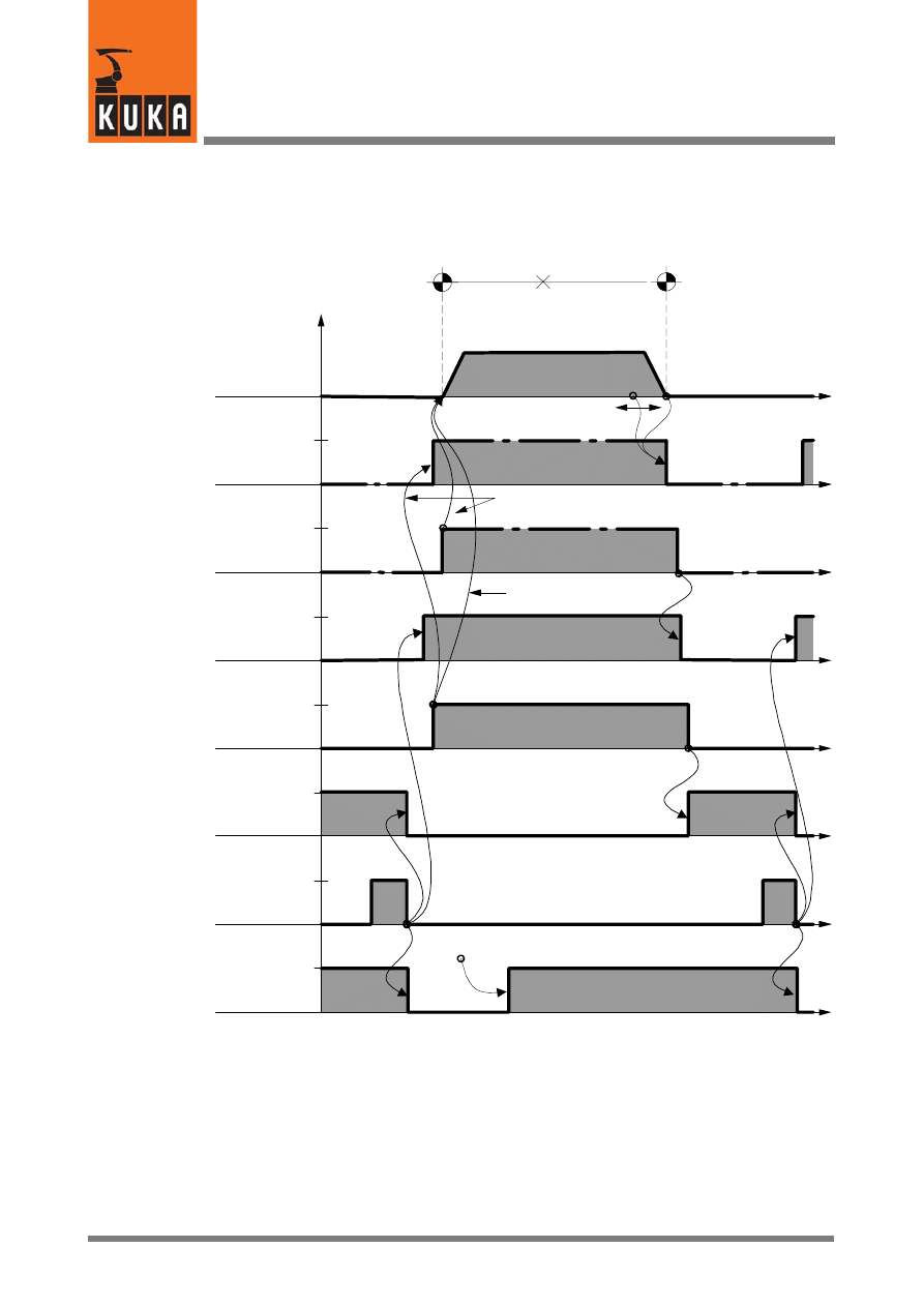
KUKA.Gripper-- and SpotTech 2.3
50 von 58
KUKA.Gripper&SpotTech2.3 07.06.00 en
of the gun (GUN_WRK=G_OPN) as well as to set the weld start signal “WLD_STRT” to
FALSE and the program number “PNUM” to ZERO.
4.7.2.2 Schematic sequence diagram for SPOT (with RETRACT)
0
t
t
t
t
t
t
t
t
t
t
t
With PRESPOT
GUN_RET
Retract stroke
activation
(output)
RET_STAT
Retract stroke
status
(input)
GUN_WRK
Working stroke
activation
(output)
WRK_STAT
Working stroke
status
(input)
WLD_STRT
Weld start
(output)
WLD_CMP
Weld
complete
(input)
PNUM
Program
number
(output)
Robot
motion
S01
S02
(Auxiliary point)
OPEN
CLOSE
OPEN
CLOSE
OPEN
CLOSE
OPEN
CLOSE
TRUE
FALSE
TRUE
FALSE
TRUE
FALSE
ADVSPOT
S.PGN01
If “RETR OPN”
selected
If “RETR CLO”
selected
After welding the spot “S01” the weld complete signal (WLD_CMP=TRUE) triggers, with its
falling edge (WLD_CMP=FALSE), the instruction for opening the working stroke of the
welding gun (GUN_WRK=G_OPN). At the same time the weld start signal
“WLD_STRT=FALSE” as well as the program number “PNUM=0” are set.
When the status message “WRK_STAT==G_OPN” is given, indicating that the working
stroke of the gun is open, movement is initiated to the next weld spot, provided the option
“RETR CLO” (gun retract stroke remains closed) has been programmed with the SPOT
command.
If the option “RETR OPN” has been programmed (the gun retract stroke is opened after the
spot has been welded), the command “GUN_RET=G_OPN” is executed. In this case,
51 von 58
KUKA.Gripper&SpotTech2.3 07.06.00 en
movement to the next weld spot is not enabled until the status signal “RET_STAT=OPEN”
is set. During this movement, the welding program number (PNUM) is output if this has been
configured in the section “ADVSPOT” of the file “USERSPOT.SRC”.
At the end point (in this example point “S02”), the control instruction is given to close the
working stroke (GUN_WRK=CLOSE). The welding program number (PNUM) is output at the
same time. If the retract stroke at point “S02” is open (RET_STAT=OPEN), the
corresponding close instruction (GUN_RET=CLOSE) is given first of course.
The status message from the welding controller that the working stroke is closed
(WRK_STAT=W_CLO) triggers the weld start (WLD_STRT=TRUE). At the conclusion of the
welding process, an instruction is given once again by means of the weld complete signal
(WLD_CMP) to open the working stroke of the gun (GUN_WRK=G_OPN).
4.7.2.3 Robot controller -- welding controller interface
The following table provides an overview of the configurable physical inputs and outputs. The
addresses refer to the extension of the file “USERSPOT.SRC” shown in Section 4.7.2.4.
Name
Description, signal states
Output / Input
(example)
PNUM
Welding program no. (max. 255 characters)
Output 1 ... 8
WLD_STRT
Weld start
Output 15
WLD_CMP
Weld complete signal (from welding controller)
Input 15
Working stroke control (SPOT)
GUN WRK
Close stroke
Open stroke
GUN_WRK
TRUE
FALSE
Output 10
FALSE
TRUE
Output 11
Working stroke status message (SPOT)
WRK STAT
Stroke closed
Stroke open
WRK_STAT
TRUE
FALSE
Input 10
FALSE
TRUE
Input 11
Retract stroke control (RETRACT)
GUN RET
Close stroke
Open stroke
GUN_RET
TRUE
FALSE
Output 12
FALSE
TRUE
Output 13
Retract stroke status message (RETRACT)
RET STAT
Stroke closed
Stroke open
RET_STAT
TRUE
FALSE
Input 12
FALSE
TRUE
Input 13
4.7.2.4 Program example for the file “USERSPOT.SRC”
&COMMENT USERSPOT package
DEF
USERSPOT (CMD :IN,S :IN )
;********************************
; USERSPOT - Package KR C1
; R2.2.x

KUKA.Gripper-- and SpotTech 2.3
52 von 58
KUKA.Gripper&SpotTech2.3 07.06.00 en
; Date: 23.03.98
; Example No 1
; SPOT / RETRACT
;********************************
DECL S_COMMAND CMD
DECL SPOT_TYPE S
Assignment of inputs/outputs
;Program No.
SIGNAL PNUM $OUT[1] TO $OUT[8]
Program number, outputs 1...8
;GUN-RETRACT
SIGNAL GUN_RET $OUT[10] TO $OUT[11]
Retract stroke (RETRACT),
outputs 10, 11
;State RETRACT
SIGNAL RET_STAT $IN[10] TO $IN[11]
Retract stroke status, inputs 10, 11
;GUN work (SPOT)
SIGNAL GUN_WRK $OUT[12] TO $OUT[13]
Working stroke (SPOT),
outputs 12, 13
;State SPOT
SIGNAL WRK_STAT $IN[12] TO $IN[13]
Working stroke status, inputs 12, 13
;Weld Start
SIGNAL WLD_STRT $OUT[15]
Weld start, output 15
;Weld done
SIGNAL WLD_CMP $IN[15]
Weld complete signal, input 15
;=================================
;GROUP Definitions
INT R_CLO,R_OPN,W_CLO,W_OPN
Retract stroke / working stroke states
R_CLO=’B0001’
R_OPN=’B0010’
W_CLO=’B0001’
W_OPN=’B0010’
;=================================
SWITCH
CMD
CASE #INIT
INIT ( )
CASE #ADVSPOT
ADVSPOT (CMD,S )
CASE #PRESPOT
PRESPOT (CMD,S )
CASE #SPOT
SPOT (CMD,S )
S_READY=TRUE
CASE #RETR
RETRACT (CMD,S )
S_READY=TRUE
ENDSWITCH
END ; END OF MAIN
;*********************************
DEF
ADVSPOT (CMD :IN,S :IN )
WLD_STRT=FALSE
Reset weld start
PNUM=S.PGNO1
Issue program number
END ;(ADVSPOT)
;*****************************

53 von 58
KUKA.Gripper&SpotTech2.3 07.06.00 en
DEF
PRESPOT (CMD :IN,S :IN )
GUN_RET=R_CLO
Close retract stroke (RETRACT)
WAIT FOR
RET_STAT==R_CLO
Waiting for “Retract closed”
GUN_WRK=W_CLO
Close working stroke
END ;(PRESPOT)
;*****************************
DEF
SPOT ( )
WAIT FOR
WRK_STAT==W_CLO
Waiting for “Working stroke closed”
WLD_STRT=TRUE
Set weld start
WAIT FOR
WLD_CMP
Waiting for weld complete
signal (TRUE)
PNUM=0
Set program number to ZERO
WAIT FOR
NOT (WLD_CMP)
Waiting for weld complete
signal (FALSE)
WLD_STRT=FALSE
Reset weld start (FALSE)
GUN_WRK=W_OPN
Open working stroke
WAIT FOR
WRK_STAT==W_OPN
Waiting for “Working stroke open”
SWITCH
S.RETR
If “RETR OPN” programmed
CASE #OPN
after weld spot:
GUN_RET=R_OPN
open retract stroke (RETRACT)
WAIT FOR
RET_STAT==R_OPN
Waiting for “Retract stroke open”
ENDSWITCH
END ;(SPOT)
;*****************************
DEF
RETRACT ( )
SWITCH
S.RETR
Retract stroke (RETRACT)
CASE #OPN
If “RETR OPN” programmed:
GUN_RET=R_OPN
open retract stroke (RETRACT)
WAIT FOR
RET_STAT==R_OPN
Waiting for “Retract stroke open”
CASE #CLO
If “RETR CLO” programmed:
GUN_RET=R_CLO
close retract stroke
WAIT FOR
RET_STAT==R_CLO
Waiting for “Retract stroke closed”
ENDSWITCH
END ;(RETR)
;*****************************
DEF
INIT ( )
PNUM=0
Set program number to ZERO
WLD_STRT=FALSE
Reset weld start
GUN_WRK=W_OPN
Open working stroke (SPOT)
WAIT FOR
WRK_STAT==W_OPN
Waiting for “Working stroke open”
GUN_RET=R_OPN
Open retract stroke (RETRACT)
WAIT FOR
RET_STAT==R_OPN
Waiting for “Retract stroke open”
S_READY=TRUE
Enable for further program execution
END ;(INIT)
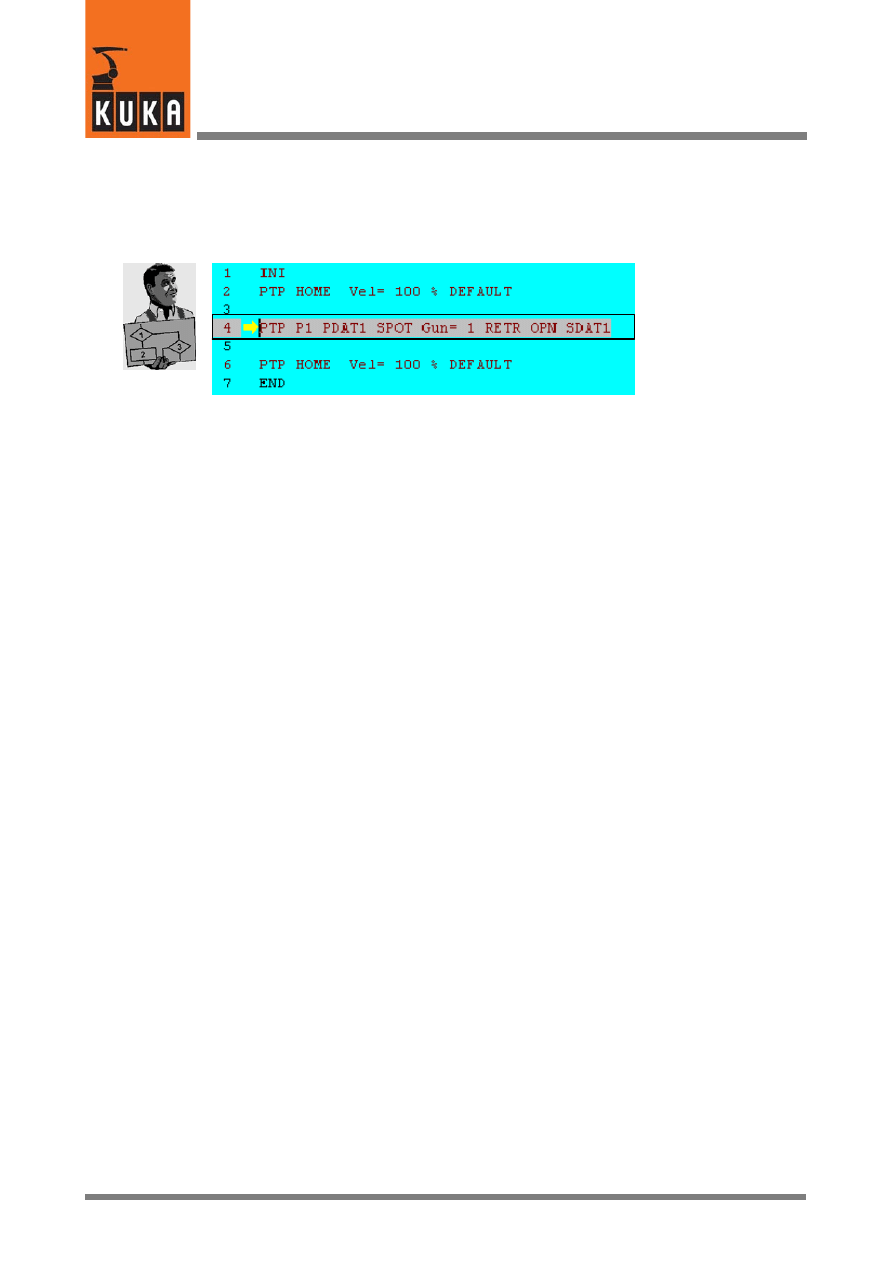
KUKA.Gripper-- and SpotTech 2.3
54 von 58
KUKA.Gripper&SpotTech2.3 07.06.00 en
4.8
Program example
A simple demonstration program (for example, DEMO01.SRC) for welding a single spot is
described in the following. Add the command “SPOT Tech”--“SPOT”--“PTP” to a skeleton
program as shown in program line 4 below.
Now move the edit cursor to line 4 and select “FOLD” -- “Act FOLD op/cl” with the menu
function “Program” (to do so you must be within the user group “Expert”). You will now see
the complete program listing for the entered command.
File “DEMO01.SRC”
PTP P1 PDAT1 SPOT Gun= 1 RETR OPN SDAT
PDAT_ACT=PPDAT1
⎫
BAS (#PTP_DAT )
⎥
FDAT_ACT=FP1
⎬
Motion parameters
BAS (#FRAMES )
⎥
BAS (#VEL_PTP,PPDAT1.VEL )
⎭
Ref. to data set (for
precalculation)
S_ACT.GUN=1
Selection of welding gun (1...5)
S_ACT.PAIR=SDEFAULT.PAIR
Selection of gun pair
S_ACT.RETR=#OPN
Retract stroke open
S_ACT.CLO_TM=SSDAT1.CLO_TM
S_ACT.PGNO1=SSDAT1.PGNO1
Welding program number
S_ACT.PGNO2=SDEFAULT.PGNO2
S_ACT.PRESS1=SSDAT1.PRESS1
S_ACT.PRESS2=SDEFAULT.PRESS2
S_READY=FALSE
USERSPOT (#ADVSPOT,S_ACT )
TRIGGER
WHEN DISTANCE=1
Trigger for gun closing
DELAY=SSDAT1.CLO_TM DO USERSPOT
(working stroke)
(#PRESPOT,S_ACT ) PRIO= -1
Trigger for early gun closing
(PRESPOT)
TRIGGER
WHEN DISTANCE=1
Trigger for weld start (SS)
DELAY=0.0 DO USERSPOT
(#SPOT,S_ACT) PRIO= -1
PTP
XP1
WAIT FOR
S_READY
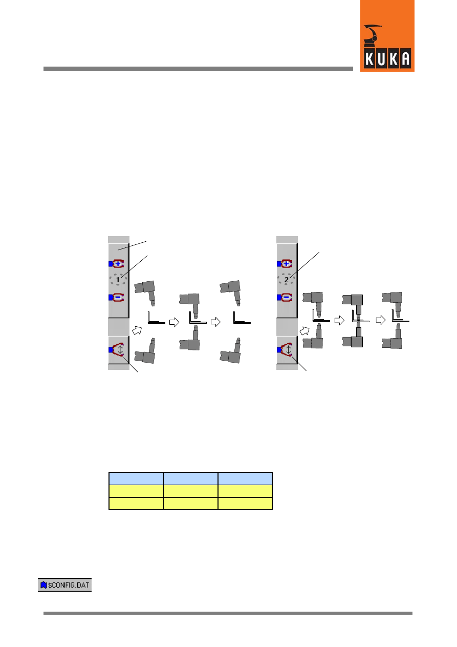
55 von 58
KUKA.Gripper&SpotTech2.3 07.06.00 en
4.9
Manual operation of the welding gun using the status keys
When carrying out tests, it is useful to be able to test the retract stroke (RETRACT) and
working stroke (SPOT) functions of the gun in addition to the gun movement, without actually
welding.
4.9.1
Separate control of RETRACT and SPOT
The configuration described below allows separate manual control of the gun retract stroke
(RETRACT) and working stroke (SPOT).
Using the “Gripper selection” status key, you can choose from the following:
-- Retract stroke (RETRACT)
--
(“Gripper”) no. 1 and
-- Working stroke (SPOT)
--
(“Gripper”) no. 2
The retract stroke (1) or the working stroke (2) can be controlled corresponding to the
selection you make with the status key for manual gripper operation.
Working stroke (SPOT)
Retract stroke (RETRACT)
GUN_WRK
OPEN
CLOSE
OPEN
GUN_RET
OPEN
CLOSE
OPEN
Operation of retract stroke
Operation of working stroke
Retract/working stroke selection
4.9.1.1 Definition of function type and assignment of physical outputs
The “GRIPPER Tech” package provides a number of gripper function types. Two function
types are available for implementing the above configuration:
Function type 1
static outputs
(for static valves)
Function type 5
pulse outputs
(for pulse valves)
Logic table for function types 1 and 5:
State
OUT1
OUT2
A
TRUE
FALSE
B
FALSE
TRUE
The changes required in the file “$CONFIG.DAT” for manual gun operation are described
below.
Static outputs
Entries in the file “$CONFIG.DAT” when using gripper function type 1:
; Definition of grippers
;==================================
INT MAXGRIPPER=8
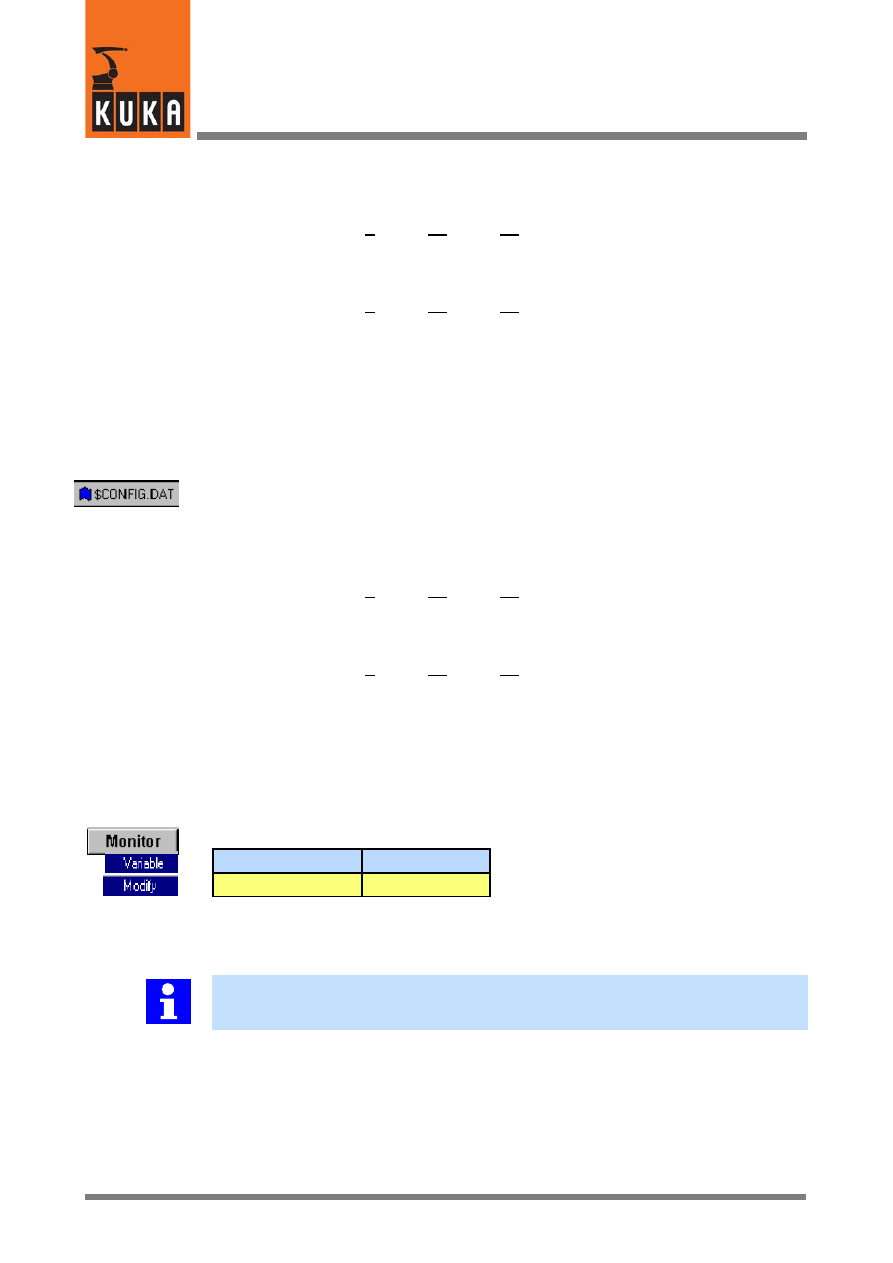
KUKA.Gripper-- and SpotTech 2.3
56 von 58
KUKA.Gripper&SpotTech2.3 07.06.00 en
DECL GRP_TYPES GRIPPER[8]
GRIPPER[1]={TYPE 1,OUT1 10,OUT2 11,
Retract stroke (RETRACT)
OUT3 0,OUT4 0,IN1 0,IN2 0,IN3 0,
Definition of function type (1) and
IN4 0,GRP_OLD 1}
assignment of the physical outputs
(in this example 10 and 11)
GRIPPER[2]={TYPE 1,OUT1 12,OUT2 13,
Working stroke (SPOT)
OUT3 0,OUT4 0,IN1 0,IN2 0,IN3 0,
Definition of function type (1) and
IN4 0,GRP_OLD 1}
assignment of the physical outputs
(in this example 12 and 13)
Pulse outputs
Entries in the file “$CONFIG.DAT” when using gripper function type 5:
; Definition of grippers
;==================================
INT MAXGRIPPER=8
DECL GRP_TYPES GRIPPER[8]
GRIPPER[1]={TYPE 5,OUT1 10,OUT2 11,
Retract stroke (RETRACT)
OUT3 0,OUT4 0,IN1 0,IN2 0,IN3 0,
Definition of function type (5) and
IN4 0,GRP_OLD 1}
assignment of the physical outputs
(in this example 10 and 11)
GRIPPER[2]={TYPE 5,OUT1 12,OUT2 13,
Working stroke (SPOT)
OUT3 0,OUT4 0,IN1 0,IN2 0,IN3 0,
Definition of function type (5) and
IN4 0,GRP_OLD 1}
assignment of the physical outputs
(in this example 12 and 13)
The pulse duration for function type 5 is preset to 0.5 seconds. It is possible to make a change
at the end of the block “Definition of grippers” in the file “$CONFIG.DAT”.
REAL GRP_PULSE_TI=0.5 ; pulse time for gripper type 5
Corresponding entry using the menu function “Monitor -- Variable -- Modify”:
Variable
Default (sec.)
GRP_PULSE_TI
0.500
The inputs (IN1 ... IN4) are not polled in these examples because the mechanical gun
function can be checked visually. For this reason the configuration and addressing of the
physical inputs are irrelevant for the manual gun control function.
In the examples above, the retract stroke control for gripper no. 1 and working stroke
control for gripper no. 2 were assigned. You can also assign other numbers if these
numbers are reserved for other applications, for example.
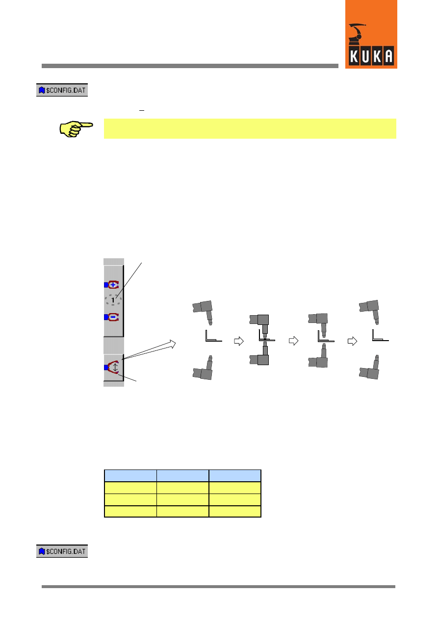
57 von 58
KUKA.Gripper&SpotTech2.3 07.06.00 en
The assignment of gripper no. 8, for example, requires the following entry in the file
“$CONFIG.DAT”:
GRIPPER[8]={TYPE 1,OUT1 10,OUT2 11, ...
Note that the value of the variable “MAXGRIPPER” must be at least as high as the
configured gripper number. “MAXGRIPPER=8” is the default setting.
4.9.2
Manual control of RETRACT and SPOT in series
The following example describes how the retract stroke and working stroke of guns with
4--way valves can be manually controlled. Switching between the following states should be
possible using the status key for manual gripper control:
-- Retract stroke (RETRACT) open, working stroke (SPOT) open
-- Retract stroke closed, working stroke closed
-- Retract stroke closed, working stroke open
GUN_RET
GUN_WRK
OPEN
OPEN
CLOSE
CLOSE
CLOSE
OPEN
Operation
Selection of welding gun 1 / 2
OPEN
OPEN
Definition of function type and assignment of physical outputs
For implementation of the above configuration, the “GRIPPER Tech H50” package provides
function type 4, with only the outputs 2 and 3 being used.
Logic table of function type 4, outputs 2 and 3:
State
OUT2
OUT3
A
FALSE
FALSE
B
TRUE
TRUE
C
TRUE
FALSE
The changes required in the file “$CONFIG.DAT” for manual gun operation are described
below.
; Definition of grippers
;==================================
INT MAXGRIPPER=8

KUKA.Gripper-- and SpotTech 2.3
58 von 58
KUKA.Gripper&SpotTech2.3 07.06.00 en
DECL GRP_TYPES GRIPPER[8]
GRIPPER[1]={TYPE 4,OUT1 10,OUT2 12,
Retract (OUT 10) and working stroke
OUT3 0,OUT4 0,IN1 0,IN2 0,IN3 0,
(OUT 12), definition of the function
IN4 0,GRP_OLD 1}
type (4) and assignment of the
physical outputs (e.g. 10 and 11)
1

Index
Index -- i
Zeichen
$CONFIG.DAT, 9, 10, 44, 45, 53
Zahlen
4/2--way valves, 9
A
Adding commands, 38
ADVSPOT, 41, 47, 48
Altering existing programs, 37
Approximation function, 16
Arrow keys, 15
Assignment of inputs/outputs, 50
at, 16, 18
B
Basic functions, 42
BLOW, 8
C
Call during advance run, 46
CASE #ADVSPOT, 46
CASE #INIT, 46
CASE #PRESPOT, 46
CASE #SPOT, 46
CHECK, 18
Check Gripper, 16, 18
CIRC, 22
Cmd Ok, 17
Continuous signal, 9
Creating a new program, 31
D
Default data set, 45
Delay, 16, 17, 19
Deleting command lines, 37
Designation of the welding gun, 22
E
Early closing of the welding gun, 26
Early closing time, 26
Early gun closing, 42
Enabling switch, 14
END, 17, 19
Exclusion from use, 8
F
FOLD, 52
Function type, 8
G
GDAT, 16
Gripper sensor interrogation, 18
GRIPPERTech, 15, 18
GRP_PULSE_TI, 9
Gun, 22
Gun opening and closing times, 43
I
Identification number, 10
INI, 20
Initialization command, 20
Initialization and configuration examples, 13
Inline form, 15, 18, 21, 23
Inline form RETRACT, 28
Inline form SPOT, 24
Inputs, 45
Issue program number, 50
L
LIN, 22
M
Manual control of RETRACT and SPOT in se-
ries, 55
Manual gripper operation, 9
Manual operation of the welding gun, 53
Manually operating a gripper, 14
Monitor, 9
O
OFF, 8
Outputs, 45
P
P1, 21
Parameter lists RETRACT, 28

Index
Index -- ii
Parameter lists SPOT, 24
PDAT, 21, 25
Peripheral interfaces, 45
Pneumatic cylinders, 9
PRESPOT, 42
Program example, 31, 49, 52
Program number output, 50
Program sequence, 41
Program structure, 44
Programmed velocity, 14
Programming a weld spot, 23
Programming gripper functions, 15
Programming the retract stroke, 27
PTP, 22
Pulse, 9
Pulse outputs, 54
R
Reduced velocity, 14
Reorientation of the welding gun, 20, 30, 38,
39
Reset weld start, 50
RETR CLO, 20, 25, 29, 48
RETR OPN, 20, 25, 29, 48
RETRACT, 9, 20, 26, 41
Retract stroke, 20, 41, 42, 50
Retract stroke after the welding process, 25
Robot motion to a weld spot, 22
S
S_READY, 46, 52
SDAT, 21, 25
Selecting the welding gun, 25
Sensor interrogation, 16
Sensors, 16
Sequence diagram for SPOT (with RETRACT),
48
Sequence diagram for SPOT (without RE-
TRACT), 47
SET, 15
Set program number to ZERO, 51
Simulation, 16
Softkey bar, 15
SPOT, 20, 22, 23, 42, 47
SPOT Gun=, 25
Spot welding, 22
START, 17, 19
State, 15, 18
Static outputs, 53
Status key, 14
System variables, 9
T
TEST1, 14
TEST2, 14
Time optimization, 43
Trigger for early gun closing, 43, 52
Trigger for weld start, 43, 52
Types of motion, 22, 27
U
USER_GRP.DAT, 10
USER_GRP.SRC, 9, 11
USERGRP.DAT, 9
USERSPOT, 45
USERSPOT.SRC, 44, 45, 46, 47, 49
V
VACUUM, 8
Vacuum gripper, 8
Variables, 9, 45
W
Wait Time, 16
Weld complete signal, 47, 48, 49, 50
Weld parameters, 22, 25
Weld start, 49, 50
Welding gun, 9
Welding gun retract stroke, 22
Welding process, 20
Welding program number, 47, 49
WORKING STROKE, 9
Working stroke, 26, 41, 42, 50
Working stroke status, 50
Document Outline
- 1 General
- 2 Installation / uninstallation / update
- 3 GripperTech
- 3.1 Basic gripper functions
- 3.1.1 Type 1 2 outputs, 4 inputs, 2 switching states
- 3.1.2 Type 2 2 outputs, 2 inputs, 3 switching states
- 3.1.3 Type 3 2 outputs, 2 inputs, 3 switching states
- 3.1.4 Type 4 3 outputs, 2 inputs, 3 switching states
- 3.1.5 Type 5 2 outputs, 4 inputs, 2 switching states
- 3.1.6 Freely programmable type
- 3.1.7 Initialization and configuration examples
- 3.2 Manually operating a gripper
- 3.3 Programming gripper functions
- 3.1 Basic gripper functions
- 4 SpotTech
- 4.1 Basic SpotTech user functions
- 4.2 Programming and operation
- 4.3 Program example
- 4.4 Altering existing programs
- 4.4.1 Altering command lines
- 4.4.2 Deleting command lines
- 4.4.3 Adding commands to an existing program
- 4.4.3.1 Description of the alteration
- 4.4.3.2 Changing the position of the welding gun ( point in space P10)
- 4.4.3.3 Reorientation of the welding gun -- inserting the command “ Motion” ( P11)
- 4.4.3.4 Moving to the point in space P12 -- inserting the command “ Motion”
- 4.4.3.5 Welding spot P13 -- inserting the command “ SPOT”
- 4.4.3.6 Moving to the weld spot P16 and welding
- 4.4.3.7 Moving to the home position
- 4.5 SpotTech configuration
- 4.6 Components of the SpotTech package
- 4.7 Adaptation to the periphery, configurable options
- 4.8 Program example
- 4.9 Manual operation of the welding gun using the status keys
Wyszukiwarka
Podobne podstrony:
23 en
gripperspottech r21 en
KST KUKA Encryption 12 en
KST PLC ProConOS 40 en
KST KUKA Encryption 11 en
Wyk-ad 2 - 23.02.05, 23
Wyk-ad 2 - 23.02.05, 23
Wyk-ad 6 - 23.03.05, 09
msg wykT-ad 1 23.09.2007r, MSG
Wyk 'ad 1 23.02.10, administracja publiczna-ćw, owi
Uk-ad Fe-Fe3C , ZAGADNIENIA, ZAGADNIENIA, 23. OBRÓBKA CIEPLNA
13 01 23 Creo en Dios
Dyrektywa PED 97 23 CE EN id 14 Nieznany
więcej podobnych podstron