CONCEPT BY OLIVIER
DROUHIN revision : 01
1
VPIS
presentation of VPIS---V1
and VPIS---V2
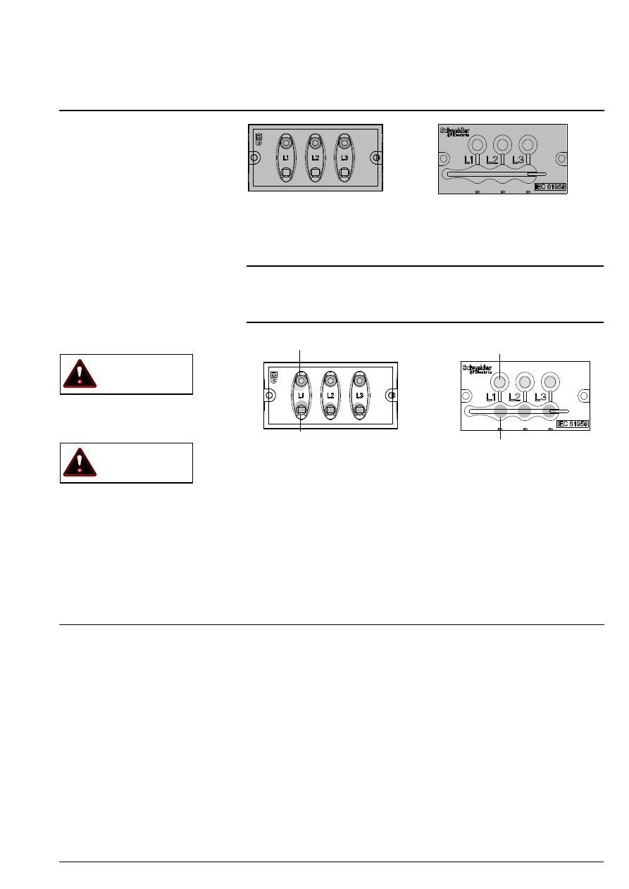
VPIS :Voltage Presence Indicating
System, a case with 3 built ---in
lights.
VPIS -- V1 : production until
February 2009.
VPIS -- V2 : production starting
from March 2009.
characteristics
Conforming to IEC 61958, relative
to voltage presence.
operating instructions
WARNING
The indication provided by a
VPIS -- V1 or V2 alone is not
sufficient to ensure that the system
is de ---energised.
INFORMATION
When the ambient lighting is
particularly bright, it may be
necessary to improve visibility by
protecting the indication.
A
B
A : voltage presence indicator
light (one for each phase)
B : connection point designed for
the connection of a phase
concordance unit (one for
each phase)
A
B
2
CONCEPT BY OLIVIER
DROUHIN revision : 01
phase concordance
unit
Phase concordance testing for
VPIS -- V1 and VPIS -- V2 must be
carried out each time a cable is
connected to a functional unit.
It is a way of making sure that all
three cables are each connected
to the corresponding phase of
the panel.
principle
The principle of the phase
concordance unit is that it allows
a check of the phase
concordance between 2
energised functional input units
on the same panel.
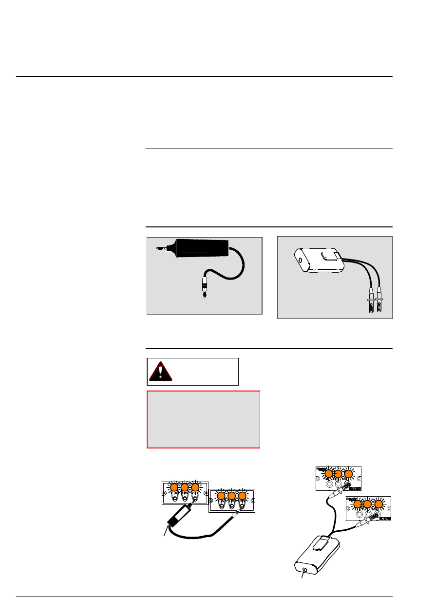
reminder of accessories that
can be used for phase
concordance test
phase concordance unit
V1 -- 51191954FA
phase concordance unit
V2 -- VPI62421
rules for the use of
phase concordance
unit
WARNING
IT IS IMPOSSIBLE TO CARRY
OUT A PHASE CONCORDANCE
TEST WITH 2 VPIS OF
DIFFERENT
TYPES
Balanced phases :
---the phase concordance unit light
(1) does not come on.
Unbalanced phases :
---the phase concordance unit light
comes on.
1
1
1
2
CONCEPT BY OLIVIER
DROUHIN revision : 01
3
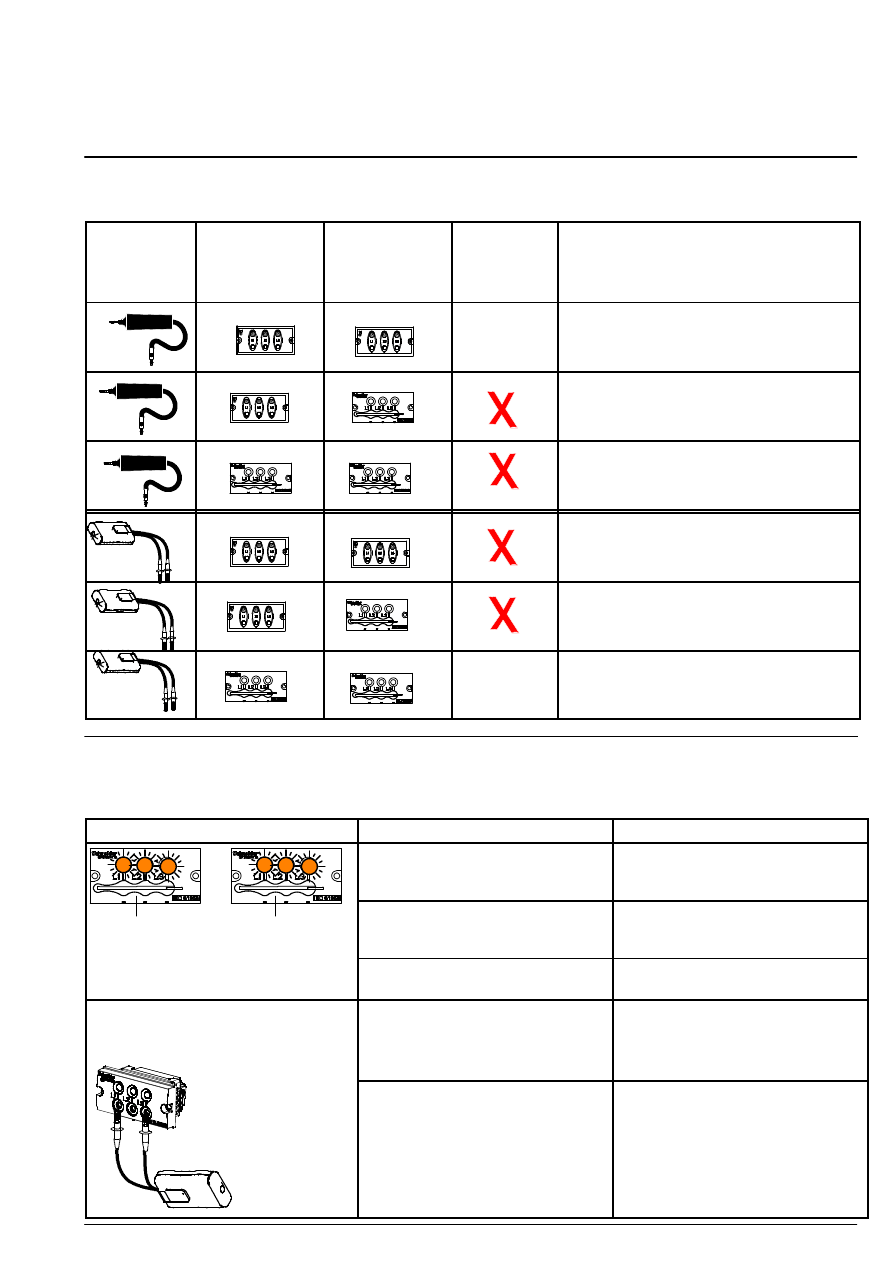
rules for choosing phase
concordance unit
phase
concordance
unit
functional unit
1
functional unit
2
compatibility
result
corrective actions
V1
V1
OK
V1
V2
OK
Replace VPIS-- V1 by VPIS-- V2.
Use a phase concordance unit V2.
V2
V2
OK
Use a phase concordance unit V2.
V1
V1
OK
Replace VPIS-- V1 units by VPIS-- V2 units
OR test with 1 phase concordance unit
V1.
V1
V2
OK
Replace VPIS-- V1 with VPIS-- V2
V2
V2
OK
check before phase
concordance test
Please refer to the previous
chapters in the event of test
malfunctioning.
TEST
RESULT
ACTION
The 3 indicator lights of each VPIS
are on.
The 2 cells are energised, the
VPIS units are operating and the
check can continue.
Visual checking of the indicator
lights on the VPIS units of functional
The 3 indicator lights of the VPIS
are off. The cell is not energised or
the VPIS is defective.
Apply power to the functional unit.
If VPIS---V1 remains unlit, replaced
it by a VPIS---V2.
Visual checking of the indicator
lights on the VPIS units of functional
unit 1 and of functional unit 2
One or 2 indicator lights unlit.
The VPIS is probably defective.
Replace by a VPIS---V2.
phase concordance
test choice
On each
functional
The indicator light of the phase
concordance unit came on twice.
You can test.
functional
unit test
phases 1
and 3.
The phase concordance unit indi-
cator light went out every second
time.
You cannot test them.
phases 1
and 3.
time.
phase concordance unit LED lit
LED unlit
lexique
or
4
CONCEPT BY OLIVIER
DROUHIN revision : 01
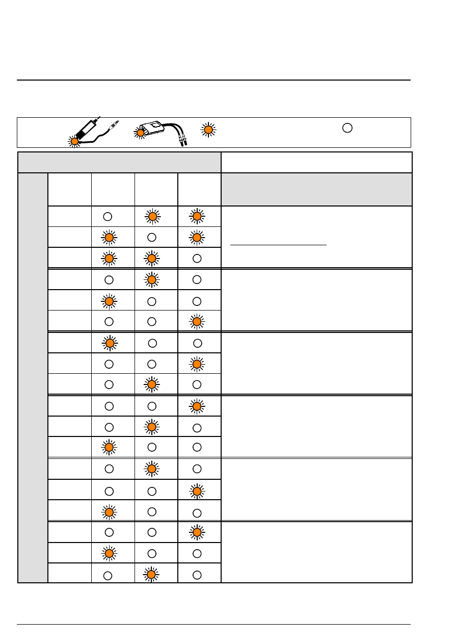
phase condordance test
The 3 indicator lights of the 2 VPIS are lit and the phase concordance unit is correct, meaning that phase
concordance test can be performed.
Functional unit n˚2
L1
L2
L3
Conclusion regarding phase concordance
L1
L2
Connection is satisfactory.
L3
Connection is satisfactory.
L1
L2
Reverse the MV cables connected to L1 and L2
and one of the functional units
L3
and one of the functional units
t
n
˚1
L1
a
l
u
n
it
L2
Reverse the MV cables connected to L2 and L3
and two of the functional units
ti
o
n
a
l
L3
and two of the functional units
F
u
n
c
t
L1
F
L2
Reverse the MV cables connected to L1 and L3
and two of the functional units
L3
and two of the functional units
L1
L2
Change the position of each MV cable on one of
the 2 functional units
L3
the 2 functional units
L1
L2
Change the position of each MV cable on one of
the 2 functional units
L3
the 2 functional units
Wyszukiwarka
Podobne podstrony:
BATERIE KONDENSATOROWE DO KOMPENSACJI MOCY BIERNEJ NISKIEGO NAPIĘCIA typ BK 55 z automatyczną regula
V1 V2 VW3, Dokumenty(1)
NADCI NIENIE WROTNE, KA
PO wyk07 v1
s10 v1
DTC v2
s7 4 v1
s9 3a v1
Elektro (v2) poprawka
DTR KWSOI 40
l1213 r iMiBM lakei v2
Prezentacja v1
KGE 750F dtr
więcej podobnych podstron