13
Service Tech Magazine/May 2001
B
osch delivered 10 million oxygen sensors to the U.S.
market in 1976 and by 1983 the number had risen to 50
million. Today, Bosch produces 33 million oxygen
sensors per year.
In 1982 Bosch launched the heated oxygen sensor which
reaches full operability in 30 seconds after a cold engine is
started. The sensor is heated to 400
o
C and has a service life of
160,000 km, twice as long as the previous unheated sensor.
In 1994 Bosch developed an oxygen sensor with a planar
ceramic structure that is fully functioning 10 seconds after the
vehicle is started.
Today’s oxygen sensor
Oxygen sensors (see Figure 1) are required today due to the
increasingly tough exhaust emissions and go hand-in-hand
with the catalytic converters. One oxygen sensor is used in the
exhaust branch right before the catalytic converter. Sometimes
a second oxygen sensor is placed in the exhaust system after the
catalytic converter of a spark-ignition engine to permit opti-
mum performance of the three-way catalytic converters.
The information obtained from the sensors indicates how
complete the combustion process is in the combustion cham-
ber. The optimum readings are obtained when the air to fuel
ratio is 14.7 to one. The stoichiometric air/fuel ratio is the mass
of 14.7 kg of air to 1 kg of gasoline theoretically necessary for
complete combustion. The excess air factor or air ratio (
λ
)
indicates the deviation of the actual air/fuel ratio from the
theoretically required ratio.
λ
= (actual induced air mass)/
(theoretical air requirement).
The first oxygen sensor
developed by Bosch was
installed in a Volvo 240/260
series vehicle 25 years ago.
Figure 1. Bosch oxygen sensor.
Service Tech Magazine/May 2001
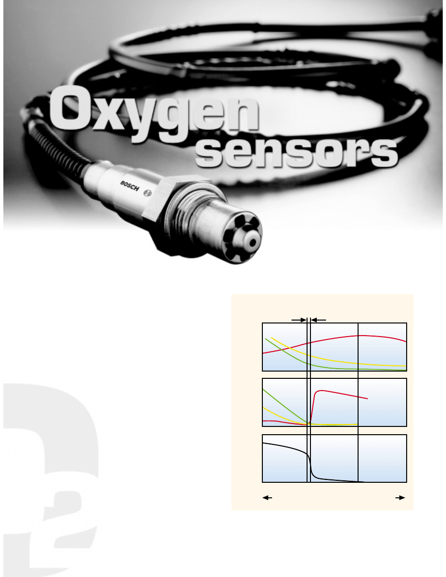
Figure 2. Control range and reductions in exhaust under three
scenarios. Number 1 is without a catalytic converter. Number 2 is with
a catalytic converter. Number 3 is the
λ
oxygen sensor voltage curve.
λ
control range (catalyst window)
1
2
3
Engine
emissions
NO
x
CO
HC
NO
x
CO
HC
Engine
emissions
λ
-sensor
voltage
0.975 1.0 1.025 1.05
rich
lean
Excess- air factor
λ
14
Service Tech Magazine/May 2001
Variations from this optimum ratio result in various levels
of emissions. Excess fuel results in the formation of hydrocar-
bons (HC) and carbon monoxide (CO). Excess air can cause
increased levels of nitrogen oxides (NOx). The oxygen sensor
or sensors can identify any variations from the ideal air/fuel
ratio and send a signal to the engine management system to
adjust the ignition and injection processes.
The three way catalytic converter is able to reduce the HC,
CO, and NOx emissions by more than 98% provided the engine
operates within a very narrow scatter range (<1%) centered
around the stoichiometric air/fuel ratio (see Figure 2). A closed
loop control system that relies on a closed loop control circuit
to maintain the air/fuel mixture consistently within the optimal
range known as the catalyst window is the best strategy.
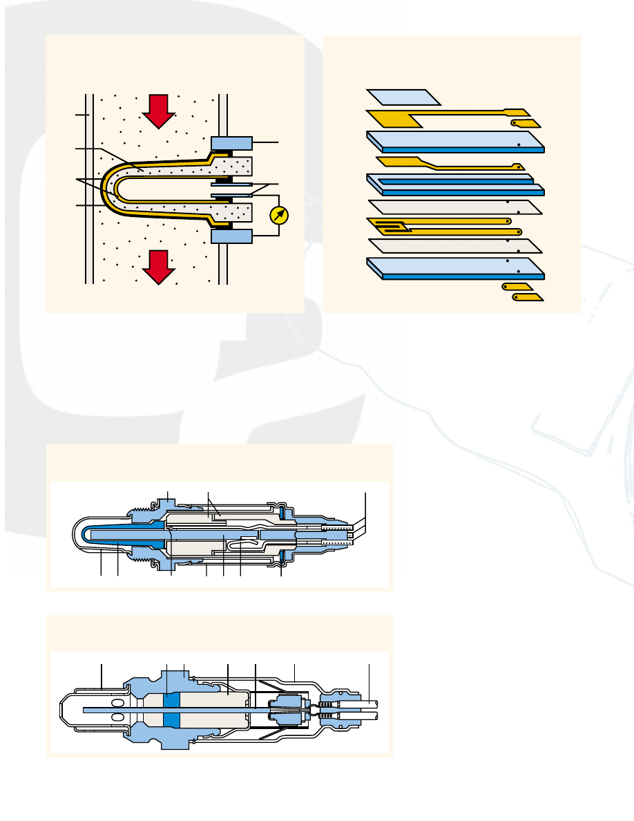
Sensor design
The oxygen sensor (see Figure 3) is a gal-
vanic oxygen concentration cell with a
solid state electrolyte. The solid state elec-
trolyte is an impermeable zirconium diox-
ide ceramic unit stabilized with yttrium
oxide. It is open on one end and closed on
the other. Mounted on both the inner and
outer surfaces are gas permeable platinum
electrodes.
The platinum electrode on the outside
acts as a miniature catalyst to support reac-
tions in the incoming exhaust gases and
bring them into a state of stoichiometric
balance. The side that is exposed to the
exhaust gases also has a porous ceramic
layer (Spinell coating) to protect against
contamination. A metal tube with numer-
ous slots guards the ceramic body against
impacts and thermal shocks. The inner
cavity is open to the atmosphere which
serves as the unit’s reference gas.
The two-state sensor operation is based
in the Nernst Principle. The sensor’s ce-
ramic material conducts oxygen ions at
temperatures 350
o
C and above. Disparities
in oxygen levels on the respective sides of
the sensor will result in the generation of
1. Ceramic coating 2. Electrodes 3. Contacts 4. Housing contacts
5. Exhaust pipe 6. Ceramic support shield (porous)
7. Exhaust gas 8. Ambient air
1. Guard tube 2. Ceramic seal assembly 3. Sensor housing 4. Ceramic support tube
5. Planar sensor element 6. Protective cap 7. Connection wire
Figure 4. Heated oxygen sensor.
1. Sensor housing 2. Ceramic support tube 3. Connection wire 4. Guard tube with slots
5. Active ceramic sensor layer 6. Contact 7. Protective cap 8. Heater element
9. Crimped connections for heater element 10. Spring washer
Figure 5. Planar oxygen sensor
Figure 3. Oxygen sensor in exhaust pipe.
1. Porous protective layer 2. External electrode
3. Sensor laminate 4. Internal electrode 5. Reference air laminate
6. Insulation layer 7. Heater 8. Heater laminate
9. Connection contacts
Figure 6. Operational layers in a planar oxygen sensor.
1
2
3
4
5
6
7
8
1
2
3
4
5
6
7
8
9
6
1
2
3
4
5
6
7
8
9
10
1
2
3
4
5
6
7
V, voltage
15
Service Tech Magazine/May 2001
electrical voltage between the two surfaces. This voltage
serves as the index of how much the oxygen levels vary on the
two sides of the sensor. The amount of residual oxygen in the
exhaust fluctuates sharply in response to the variation in the
induction mixture’s air/fuel ratio.
Oxygen sensitive voltage generation ranges from 800 to
1000 millivolts for rich mixtures to as low as 100 millivolts for
lean mixtures. The transition from rich to lean corresponds to
450 to 500 millivolts.
Heated oxygen sensor
An electric heater element (see Figure 4) is used to warm the
ceramic material when the engine is operating at low load
factors. At the higher load factors the sensor’s temperature is
determined by the exhaust gas. The heated oxygen sensor helps
ensure low and stable emissions due to the consistent mainte-
nance of optimal operating temperatures.
Planar
λ
oxygen sensor
The basic operating concept (see Figure 5) is the same as the
heated finger- type sensor in that it generates a response curve
with a characteristic jump at
λ
equal to one. The planar sensor
is distinguished from the finger type by:
• the solid body electrolyte consists of ceramic layers
• a solid ceramic sealant retains the sensor element within the
sensor casting
• a dual-wall guard tube protects the sensor element against
excessive thermal and physical stresses
The individual active layers (see Figure 6) are manufactured
using silk-screening techniques. Stacking laminated layers
with various configurations makes it possible to integrate a
heater within the sensor element.
Wide band
λ
oxygen sensor
This sensor expands on the principle of the Nernst unit (two-
state sensor function) by incorporating a second chamber, the
pump cell (see Figure 7). It is through this small slot in this
pump cell that the exhaust gas enters the actual monitoring
chamber (diffusion gap) in the Nernst cell. This configuration
contrasts with the layout of the two-state sensor by maintaining
a consistently stoichiometric air/fuel ratio in the chamber.
Electronic circuitry modulates the voltage supply to maintain
the composition of the gas in the monitoring chamber at a
consistent
λ
equals one. The pump cell corresponds to lean
exhaust by discharging oxygen from the diffusion gap to the
outside, but reacts to rich exhaust by pumping oxygen from the
surrounding exhaust gas into the diffusion gap, reversing the
direction of the current. Because the pumping current is also
proportional to the oxygen concentration and/or oxygen defi-
ciency, it serves as an index of the excess air-factor of the
exhaust gas. An integral heater unit ensures an operating
temperature of at least 600
o
C.
The two-state unit uses the voltage at the Nernst cell as a
direct measurement signal while the wide band sensor employs
special processing and control circuitry to set the pumping
current. This current is then monitored and measured as an
index of the exhaust gas’s excess-air factor. Because sensor
operation is no longer dependent on the step function response
of the Nernst cell, air factors ranging from 0.7 to 4 can be
monitored as a continuous progression. Thus
λ
control of the
engine can proceed on a reference spectrum instead of depend-
ing solely upon a single point.
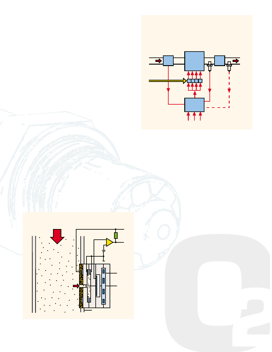
Closed loop control
The oxygen sensor relays a voltage signal to the electronic
engine management unit which then issues a command to the
injection system to enrichen or lean out the mixture as indicated
by the oxygen sensor’s signal voltage (see Figure 8). The
system thus counters lean mixtures by increasing the injected
fuel quantity and rich mixtures by reducing it.
Information and illustrations for this article supplied by
Bosch.
Interesting? Circle 11
Not interesting: Circle 12
1. Nernst cell 2. Reference cell 3. Heater 4. Diffusion gap
5. Pump cell 6. Exhaust pipe
15
Figure 7. Design of a continuous action, wide-band oxygen sensor
showing the sensor’s installation in the exhaust pipe.
2
Figure 8. Diagram of closed a
λ
closed-loop mixture control.
1
3
4
5
6
+
-
1. Mass airflow sensor 2. Engine 3a. Oxygen sensor 1
3b. Oxygen sensor 2 4. Catalytic converter 5. Injectors
6. Electronic control unit
Vv Valve control voltage Vs sensor voltage Qe injection quantity
Air
Fuel
Exhaust gas
Qe
Vsa
Vv
1
2
3a
4
5
6
Vsb
3b
Wyszukiwarka
Podobne podstrony:
Bosch HFM5 Sensors
1480 Replacing oxygen sensor
G 2 0 DOHC Heated Oxygen Sensor doc
sensors oxygen
SI – Sensory Integration
sensoryka wrażliwość czuciowa
BOSCH HDI EDC15C2 injection system (2)
integracja sensoryczna5 id 2181 Nieznany
Terapia Integracji Sensorycznej Opr, metody pracy
POMIAR DŁUGOŚCI I OBWODÓW KOŃCZYN GÓRNYCH I DOLNYCH, utp, Sensory i pomiary wielkości nieelektryczny
Terapia dzieci z sensoryzmami, Autyzm
Wprowadzenie do teorii integracji sensorycznej
Co to jest integracja sensoryczna
d7067240 7846 11dc a67c 0019bbdf5d02 Proximity sensor capactivite
ECU Bosch Kts300
Analiza sensoryczna produktu projekt id 61348 (2)
więcej podobnych podstron