
HORIZONTAL SLIDE-VALVE ENGINE
The engine illustrated in Figs. 53 to 66 will
give sufficient scope for energy and handi-
ness with drill and soldering iron. The writer
made an engine of the same kind, differing
only from that shown in the design of the
cross head guides, without the assistance
of a lathe, except for turning the piston and
fly wheel -- the last bought in the rough.
Files, drills, taps, a hack saw, and a
soldering iron did all the rest of the work.
Solder plays so important a part in the
assembling of the many pieces of the
engine that, if the machine fell into the fire,
a rapid disintegration would follow. But in
actual use the engine has proved very
satisfactory; and if not such as the highly-
skilled model-maker with a well-equipped
workshop at his command would prefer to
expend his time on, it will afford a useful
lesson in the use of the simpler tools. Under
50 lbs. of steam it develops sufficient power
to run a small electric-lighting installation,
or to do other useful work on a moderate
scale.
T
he principal dimensions of the engine are
as follows;
1. Bedplate (sheet zinc), 13-1/2 inches
long; 4-1/2 inches wide; 1/8 inch thick.
2. Support of bedplate (1/20 inch zinc), 3
inches high from wooden base to
underside of bedplate.
3. Cylinder (mandrel-drawn brass tubing),
1-1/2 inches internal diameter; 2-13/16
inches long over all.
4. Piston, 1-1/2 inches diameter; 1/2 inch
long.
5. Stroke of piston, 2-1/4 inches.
6. Connecting rod, 5 inches long between
centers;
7. 5/16 inch diameter.
8. Piston rod, 5-1/8 inches long; 1/4 inch
diameter.
9. Valve rod, 4-1/8 inches long; 3/16 inch
diameter.
10.Crank shaft, 5 inches long; 1/2 inch
diameter.
11.Center line of piston rod, 1-1/4 inches
laterally from near edge of bed; 1-5/8
inches from valve-rod center line; 1-5/8
inches vertically above bed.
12.Center line of crank shaft, 10-3/8 inches
from cross center line of cylinder.
13.Bearings, 1 inch long.
14.Eccentric, 9/32-inch throw.
15.Fly wheel, diameter, 7-1/2 inches;
width, 1 inch; weight, 6 lbs.
16.Pump, 3/8-inch bore; 3/8-inch stroke;
plunger, 2 inches long.
Page 1
HORIZONTAL SLIDE-VALVE ENGINE
Page 2
HORIZONTAL SLIDE-VALVE ENGINE
Page 3
HORIZONTAL SLIDE-VALVE ENGINE
Other dimensions will be gathered from the
various diagrams of details. The reader
will, of course, suit his own fancy in
following these dimensions, or in working to
them on a reduced scale, or in modifying
details where he considers he can effect his
object in a simpler manner.
The diagrams are sufficiently explicit to render
it unnecessary to describe the making of the
engine from start to finish, so remarks will be
limited to those points which require most
careful construction and adjustment.
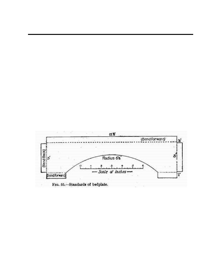
The Bedplate
This should be accurately squared and
mounted on its four arch-like supports. (For
dimensions, consult Fig. 55.) Half an inch is
allowed top and bottom for the turnovers by
which the supports are screwed to the
bedplate and base. The ends of the longer
supports are turned back so as to lie in front
of the end supports, to which they may be
attached by screws or solder, after all four
parts have been screwed to the bed. Care
must be taken that the parts all have the
same height. Drill all holes in the turnovers
before bending. Use 1/8-inch screws. Turn the
bed bottom upwards, and stand the four
supports, temporarily assembled, on it upside
down and in their correct positions, and mark
off for the 3/32-inch holes to be drilled in the
bed. A hole 3/4 inch in diameter should be cut
in the bedplate for the exhaust pipe, round a
center 2 inches from the end and 1-5/8 inches
from the edge on the fly-wheel side, and two
more holes for the pump.
Page 4
HORIZONTAL SLIDE-VALVE ENGINE
Making the Cylinder Slide and Valve
The cylinder barrel must be perfectly
cylindrical and free from any dents. Mandrel-
drawn brass tubing, 1/16-inch thick, may be
selected. If you cannot get this turned off at
the ends in a lathe, mark the lines round it for
working to with the aid of a perfectly straight
edged strip of paper, 2-13/16 inches wide,
rolled twice round the tube. The coils must lie
exactly under one another. Make plain
scratches at each end of the paper with a
sharp steel point. Cut off at a distance of
1/16-inch from the lines, and work up to the
lines with a file, finishing by rubbing the ends
on a piece of emery cloth resting on a hard,
true surface.
A square-cornered notch 1/8 inch deep and
7/8 inch wide must now be cut in each end of
the barrel, the two notches being exactly in
line with one another. These are to admit
steam from the steam ways into the cylinder.
Page 5
HORIZONTAL SLIDE-VALVE ENGINE
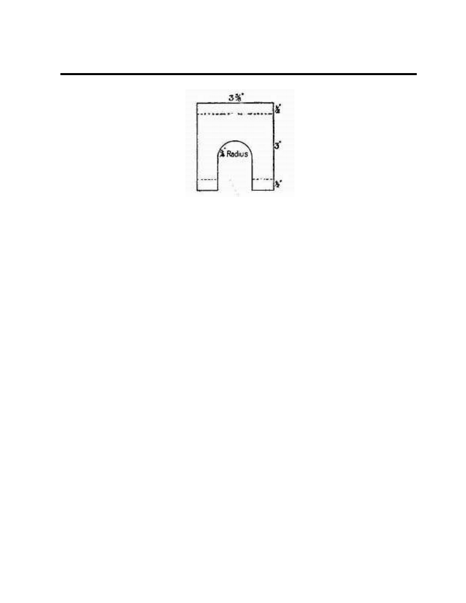
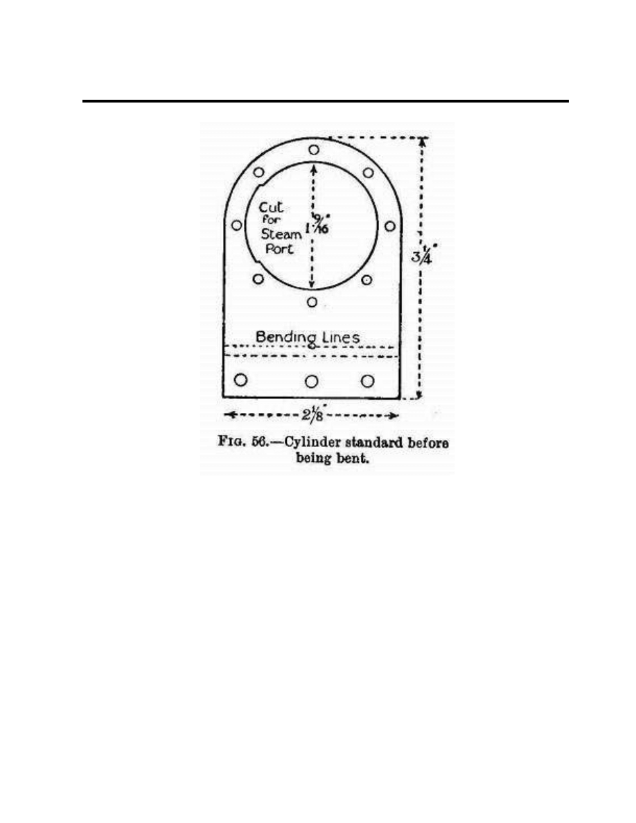
Cylinder Standards
Use 5/64 or 3/32 inch brass plate for these.
Two pieces of the dimensions shown in Fig. 56
are needed. Scratch a line exactly down the
middle of each, and a cross line 1/2 inch from
one end. The other end should be marked,
cut, and filed to a semicircle. Drill three 3/16-
inch holes in the turnover for the holding-
down screws. The two standards should now
be soldered temporarily together at the round
ends and trued up to match each other
exactly. Place them in the vice with the
bending lines exactly level with the jaws, split
the turnovers apart, and hammer them over
at right angles to the main parts. Whether this
has been done correctly may be tested by
placing the standards on a flat surface. Take
the standards apart, and scratch a cross line
on each 1-5/8 inch from the lower surface of
the foot on the side away from the foot. Make
a punch mark where the line crosses the
vertical line previously drawn, and with this as
center describe a circle of the diameter of the
outside of the barrel. Cut out the inside and
file carefully up to the circle, stopping when
the barrel makes a tight fit. On the inside of
the hole file a nick 1/8 inch deep, as shown in
Fig. 56. Remember that this nick must be on
the left of one standard and on the right of the
other, so that they shall pair off properly.
Standards and barrel must now be cleaned for
soldering. Screw one standard down to a wood
base; slip one end of the barrel into it; pass
the other standard over the other end of the
barrel, and adjust everything so that the
barrel ends are flush with the, outer surfaces
Page 6

HORIZONTAL SLIDE-VALVE ENGINE
of the standard, and the nicks of the barrel in
line with the standard nicks. Then screw the
other standard to the base. Solder must be
run well into the joints, as these will have to
stand all the longitudinal working strain.
The next step is the fitting of the cylinder
covers. If you can obtain two stout brass discs
2-1/8 inches in diameter, some trouble will be
saved; otherwise you must cut them out of
3/32-inch plate. The center of each should be
marked, and four lines 45 degrees apart be
scratched through it from side to side. A circle
of 15/16-inch radius is now drawn to cut the
lines, and punch marks are made at the eight
points of intersection. Solder the covers lightly
to the foot side of their standards, marked
sides outwards, and drill 1/8-inch holes
through cover and standard at the punch
marks. Make matching marks on the edges.
Unsolder the covers, enlarge the holes in them
to take 5/32-inch screws; and tap the holes in
the standards. This method will ensure the
holes being in line, besides avoiding the
trouble of marking off the standards
separately.
Bore a 1/4-inch hole in the center of one
cover--be sure that it is the right one--for the
piston rod.
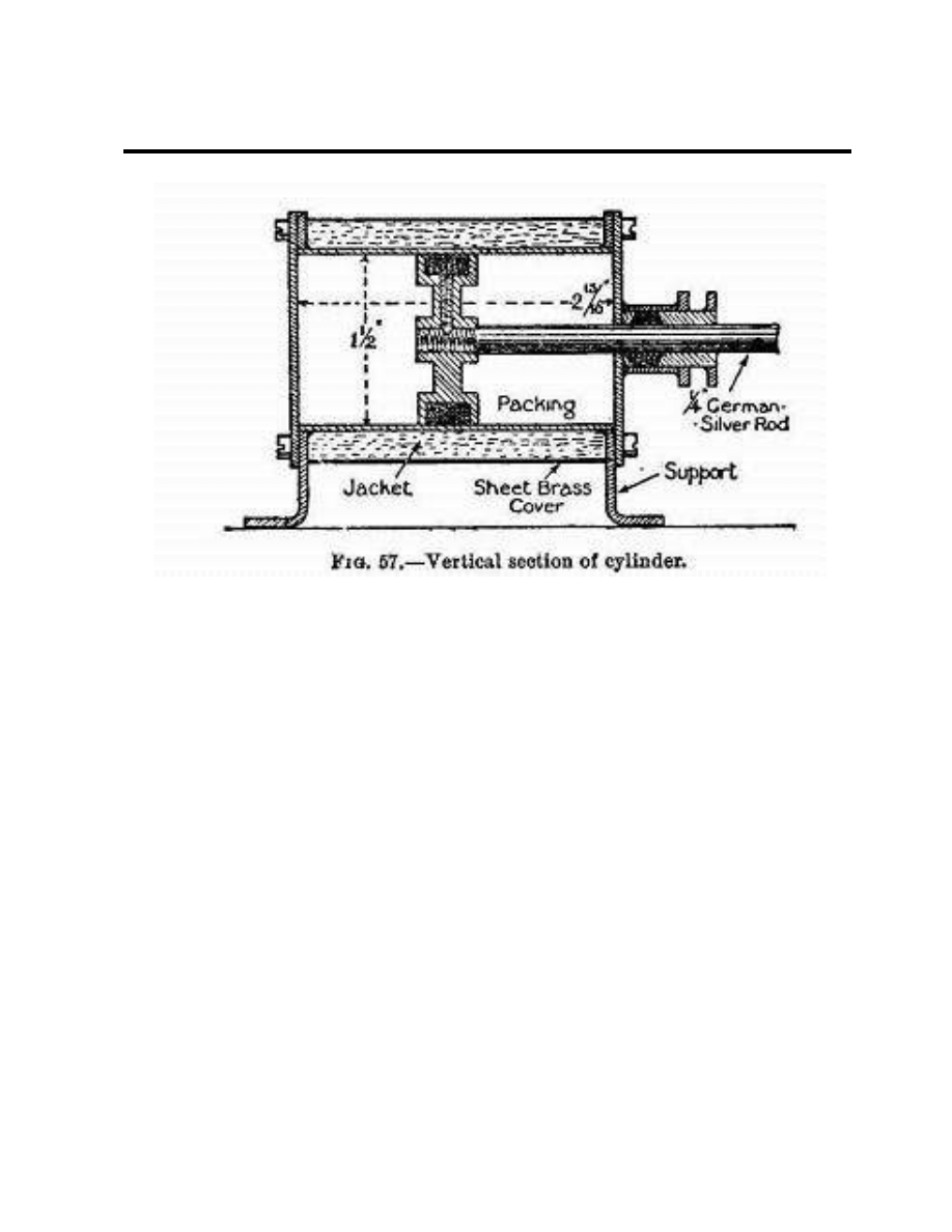
You can now proceed to the making of the
piston-rod gland (Fig. 54, G1). Fig. 57 shows
how this is built up of pieces of tubing and
brass lugs for the screws. If possible, get the
tubular parts trued in a lathe.
Before the gland is soldered to the cover, the
cover should be put in place, the piston rod
attached to the piston, and the parts of the
gland assembled. Push the piston rod through
the cover until the piston is hard up against
the back of the cover. Slip the gland over the
rod, turn it so that the screws are parallel to
the foot of the standard, and make the solder
joint. This is the best way of getting the gland
exactly concentric with the cylinder so that the
piston rod shall move without undue friction.
But you must be careful not to unsolder the
cylinder from its standard or the parts of the
gland. Blacken the piston rod in a candle
flame to prevent solder adhering.
Page 7
HORIZONTAL SLIDE-VALVE ENGINE
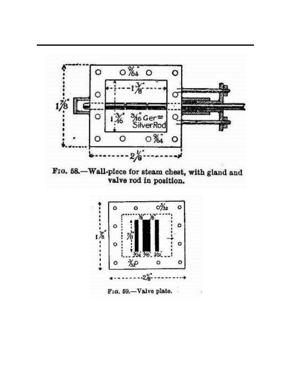
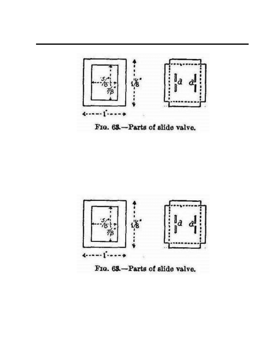
Steam Chest
The walls of the steam chest are best made in
one piece out of 1/2-inch brass by cutting out
to the dimension given in Fig. 58. A sharp fret
saw will remove the inside rectangle. Get both
inside and outside surfaces as square as
possible in all directions, and rub down the
two contact faces on emery cloth supported by
an old looking-glass.
Two perfectly flat plates of 1/8-inch brass are
cut to the size given in Fig. 59, or a little
longer both ways, to allow for working down
to the same area as the wall-piece. This
operation should be carried out after soldering
the three pieces together. File and rub the
sides until no projections are visible. Then drill
twelve 3/32-inch holes right through the three
parts. After separating them, the holes in the
walls and what will be the cover must be
enlarged to an easy fit for 1/8-inch bolts, and
the valve plate tapped.
Now drill 3/16-inch holes centrally through the
ends of the walls for the valve rod. If the first
hole is drilled accurately, the second hole
should be made without removing the drill, as
this will ensure the two holes being in line. If,
however, luck is against you, enlarge the
holes and get the rod into its correct position
by screwing and soldering small drilled plates
to the outside of the chest. Also drill and tap a
hole for the lubricator. The attachment of the
gland (Fig. 54, G2) is similar to that of the
cylinder gland, and therefore need not be
detailed.
Page 8
HORIZONTAL SLIDE-VALVE ENGINE
Page 9
HORIZONTAL SLIDE-VALVE ENGINE
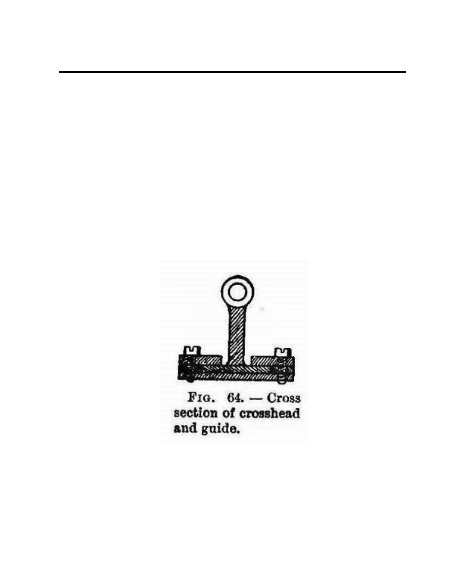
The Valve Plate (Fig. 59)
Three ports must be cut in this--a central one,
7/8 by 3/32 inch, for the exhaust; and two
inlets, 7/8 by 3/32 inch, 1/8 inch away from
the exhaust. These are easily opened out if a
series of holes be drilled along their axes.
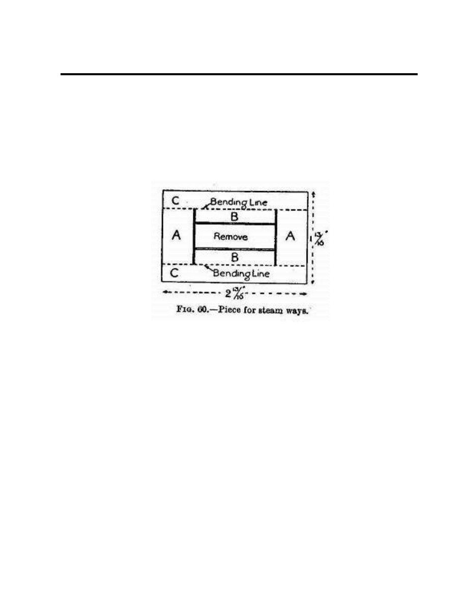
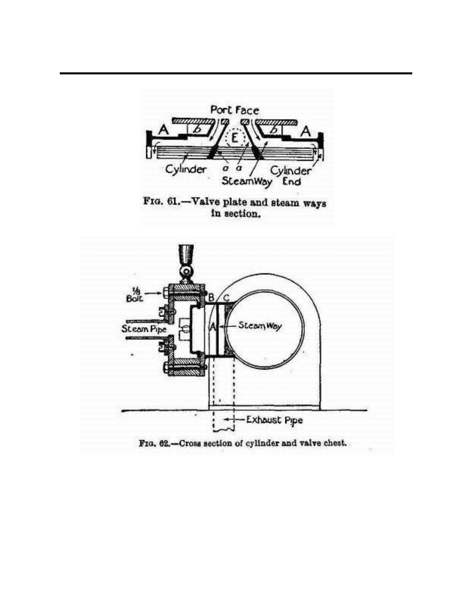
The Steam Ways
The formation of the steam ways between
valve plate and cylinder is the most ticklish bit
of work to be done on the engine as it entails
the making of a number of solder joints close
together.
We begin by cutting out of 1/20-inch sheet
brass a piece shaped as in Fig. 60. Parallel to
the long edges, and 3/8 inch away, scribe
bending lines. Join these by lines 5/8 inch
from the short edges, and join these again by
lines 1/4 inch from the bending lines. Cuts
must now be made along the lines shown
double in Fig. 60. Bend parts CC down and
parts BB upwards, so that they are at right
angles to parts AA. The positions of these
parts, when the piece is applied to the
cylinder, are shown in Fig. 62.
One must now make the bridge pieces (Fig.
61, a, a) to separate the inlet passages from
the exhaust. Their width is the distance
between the bent-down pieces CC of Fig. 60,
and their bottom edges are shaped to the
curvature of the cylinder barrel. Finally, make
the pieces bb (Fig. 61), which form part of the
top of the steam ways.
In the assembling of these parts a blowpipe
spirit lamp or a little "Tinol" soldering lamp
will prove very helpful.
The following order should be observed:
(1.) Solder the piece shown in Fig. 60 to the
cylinder barrel by the long edges, and to the
cylinder supports at the ends. This piece
must, of course, cover the steam ports in the
cylinder.
(2.) Put pieces aa (Fig. 61) in position, with
their tops quite flush with the tops of BB (Fig.
62), and solder them to the cylinder barrel
and sides of the steam-way piece.
Page 10
HORIZONTAL SLIDE-VALVE ENGINE
Page 11
HORIZONTAL SLIDE-VALVE ENGINE
(3.) Solder the valve plate centrally to BB, and
to the tops of aa, which must lie between the
central and outside ports. Take great care to
make steam-tight joints here, and to have the
plate parallel to the standards in one direction
and to the cylinder in the other.
(4.) Solder in pieces bb. These should be a
tight fit, as it is difficult to hold them in place
while soldering is done.
(5.) Bore a 5/16-inch hole in the lower side of
the central division and solder on the exhaust
pipe.
Page 12

HORIZONTAL SLIDE-VALVE ENGINE
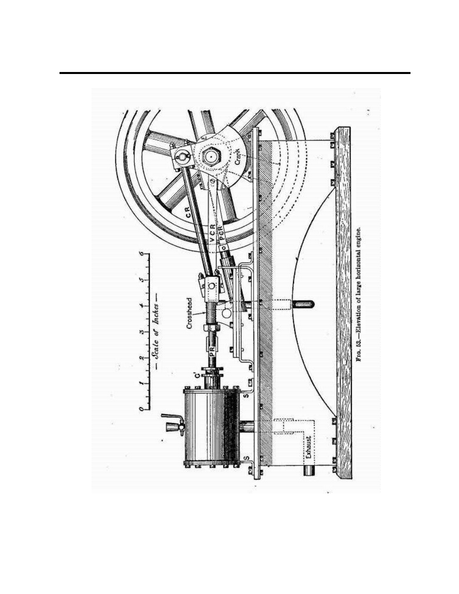
The Crank and Crank Shaft
The next thing to take in hand is the fixing of
the crank shaft. This is a piece of 3/8 or 1/2
inch steel rod 5 inches long.
The bearings for this may be pieces of brass
tubing, fitting the rod fairly tight. By making
them of good length--1 inch--the wear is
reduced to almost nothing if the lubricating
can is used as often as it should be.
Each bearing is shown with two standards.
The doubling increases rigidity, and enables
an oil cup to be fixed centrally.
The shape of the standards will be gathered
from Fig. 53, their outline being dotted in
behind the crank.
Cut out and bend the standards--after drilling
the holes for the foot screws--before
measuring off for the centers of the holes; in
fact, follow the course laid down with regard
to the cylinder standards.
Make a bold scratch across the bedplate to
show where the center line of the shaft should
be, and another along the bed for the piston-
rod center line. (Position given on p. 138.)
Bore holes in the bearings for the oil cups,
which may be merely forced in after the
engine is complete.
The crank boss may be made out of a brass
disc 2-3/4 inches diameter and 3/16 inch
thick, from which two curved pieces are cut to
reduce the crank to the shape shown in Fig.
53. The heavier portion, on the side of the
shaft away from the crank pin, helps to
counterbalance the weight of the connecting
and piston rods. In Fig. 54 (plan of engine)
you will see that extra weight in this part has
been obtained by fixing a piece of suitably
curved metal to the back of the boss.
The mounting of the crank boss on the shaft
and the insertion of the crank pin into the
boss might well be entrusted to an expert
mechanic, as absolute "squareness" is
essential for satisfactory working. Screw-
thread attachments should be used, and the
crank-shaft should project sufficiently to allow
room for a flat lock nut. The crank pin will be
rendered immovable by a small lock screw
penetrating the boss edge ways and engaging
with a nick in the pin.
Fixing the Standards and Bearings
Place the two bearings in their standards and
slip the crank shaft through them. Place
standards on the bed, with their center lines
on the crank-shaft center line. The face of the
crank should be about 3/8 inch away from the
piston rod center line. Bring the nearer
bearing up against the back of the disc, and
arrange the standards equidistantly from the
ends of the bearing. The other bearing should
overlap the edge of the bed by about 1/8 inch.
Get all standards square to the edge of the
bed, and mark off the positions of screw holes
in bed. Remove the standards, drill and tap
the bed-plate holes, and replace parts as
before, taking care that the lubricating holes
in the bearings point vertically upwards. Then
solder bearings to standards.
If any difficulty is experienced in getting all
four standards to bed properly, make the
bearing holes in the two inner ones a rather
easy fit. The presence of the crank-shaft will
assure the bearings being in line when the
soldering is completed.
The standards and bed should have matching
marks made on them.
The Eccentric
This can be formed by soldering two thin
brass discs 1-15/16- inch diameter
concentrically to the sides of a disc of 1-
15/16-inch diameter and 5/16 inch thick. The
center of the shaft hole must be exactly 9/32
inch from the center of the eccentric to give
Page 13
HORIZONTAL SLIDE-VALVE ENGINE
the proper valve-travel. Drill and tap the
eccentric edge ways for a lock screw.
A piece to which the eccentric strap, eccentric
rod, and pump rod are attached is cut out of
5/16-inch brass. Its shape is indicated in
Figure 53. The side next the eccentric must be
shaped as accurately as possible to the radius
of the eccentric. The strap, of strip brass, is
fastened to the piece by four screws, the
eccentric rod by two screws.
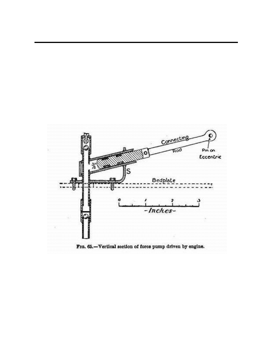
Crosshead and Guides
The crosshead (Figs. 53 and 54) is built up by
soldering together a flat foot of steel, a brass
upright, and a tubular top fitting the piston
rod. The guides, which consist of a bed,
covers, and distance-pieces united by screws
(Fig. 64), have to withstand a lot of wear, and
should preferably be of steel. The importance
of having them quite flat and straight is, of
course, obvious.
The last 1-3/8 inches of the piston rod has a
screw thread cut on it to engage with a
threaded hole in the fork (cut out of thick
brass plate), to which the rear end of the
connecting rod is pinned, and to take the lock
nut which presses the crosshead against this
fork.
Assuming that all the parts mentioned have
been prepared, the cylinder should be
arranged in its proper place on the bed, the
piston rod centrally over its center line. Mark
and drill the screw holes in the bed.
Page 14

HORIZONTAL SLIDE-VALVE ENGINE
The Valve Gear. -- We may now attend to
the valve gear. A fork must be made for the
end of the valve rod, and soldered to it with
its slot at right angles to the slots which
engage with the valve lugs. Slip the rod into
the steam chest, put the valve on the rod, and
attach the chest (without the cover) to the
valve plate by a bolt at each corner. Pull the
valve forward till the rear port is just
uncovered, and turn the eccentric full forward.
You will now be able to measure off exactly
the distance between the centers of the valve-
rod fork pin and the rear screw of the
eccentric. The valve connecting rod (Fig. 53,
VCR) should now be made and placed in
position. If the two forward holes are filed
somewhat slot-shaped, any necessary
adjustment of the valve is made easier. If the
adjustment of VCR and the throw of the
eccentric are correct, the valve will just
expose both end ports alternately when the
crank is revolved. If one port is more exposed
than the other, adjust by means of the
eccentric screws till a balance is obtained.
Should the ports still not be fully uncovered,
the throw of the eccentric is too small, and
you must either make a new eccentric or
reduce the width of the valve. (The second
course has the disadvantage of reducing the
expansive working of the steam.) Excess
movement, on the other hand, implies too
great an eccentric throw.
Setting the Eccentric
Turn the crank full forward, so that a line
through the crank pin and shaft centers is
parallel to the bed. Holding it in this position,
revolve the eccentric (the screw of which
should be slackened off sufficiently to allow
the eccentric to move stiffly) round the shaft
in a clockwise direction, until it is in that
position below the shaft at which the front
steam port just begins to show. Then tighten
up the eccentric lock screw.
1
The Connecting Rod. -- The length of this
from center to center of the pins on which it
works should be established as follows:--Slip
over the piston rod a disc of card 1/32 inch
thick. Then pass the rod through the gland
and assemble the crosshead and fork on its
end, and assemble the guides round the
crosshead foot. Turn the crank pin full
forward, pull the piston rod out as far as it will
come, measure the distance between pin
centers very carefully, and transfer it to a
piece of paper.
The rod consists of a straight central bar and
two rectangular halved ends. The ends should
be cut out of brass and carefully squared.
Through their exact centers drill 1/8-inch
holes, and cut the pieces squarely in two
across these holes. The sawed faces should be
filed down to a good fit and soldered together.
Now drill holes of the size of the pins, using
what remains of the holes first made to guide
the drill. The bolt holes are drilled next, and
finally the holes for lubrication and those to
take the rods. Then lay the two ends down on
the piece of paper, so that their pinholes are
centered on the center marks, and the holes
for the rod are turned towards one another.
Cut off a piece of steel rod of the proper
length and unsolder the ends. The rod pieces
must then be assembled on the rod, and with
it be centered on the paper and held in
position while the parts are soldered together.
OTHER DETAILS
Adjusting the Guides
Put the connecting rod in place on its pins,
and revolve the crank until the guides have
1 The reader is referred to an excellent little treatise,
entitled "The Slide Valve" (Messrs. Percival Marshall
and Co., 26 Poppin's Court, Fleet Street, E.C. Price
6d.), for a full explanation of the scientific principles
of the slide valve.]
Page 15
HORIZONTAL SLIDE-VALVE ENGINE
taken up that position which allows the
crosshead to move freely. Then mark off the
holes for the guide holding-down screws, and
drill and tap them.
Packings
.The glands and piston should be packed with
asbestos string. Don't be afraid of packing too
tightly, as the tendency is for packing to get
slacker in use. The rear end of the cylinder
should be beveled off slightly inside, to allow
the packed piston to enter easily.
Joints
The cylinder head and valve chest joints
should be made with stout brown paper
soaked in oil or smeared with red lead. All
screw holes should be cut cleanly through the
paper, and give plenty of room for the screws.
When making a joint, tighten up the screws in
rotation, a little at a time so as not to put
undue strain on any screw. Wait an hour or
two, and go round with the screw-driver
again.
Page 16

HORIZONTAL SLIDE-VALVE ENGINE
Lubrication
When the engine is first put under steam,
lubrication should be very liberal, to assure
the parts "settling down" without undue wear.
The Pump
Figure 65 shows in section the pump, which
will be found a useful addition to the engine.
(For other details, see Figs. 53 and 54.) Its
stroke is only that of the eccentric, and as the
water passages and valves are of good size, it
will work efficiently at high speed. The method
of making it will be obvious from the
diagrams, and space will therefore not be
devoted to a detailed description. The valve
balls should, of course, be of gun-metal or
brass, and the seatings must be prepared for
them by hammering in a steel ball of the
same size.
In practice it is advisable to keep the pump
always working, and to regulate the delivery
to the boiler by means of a by-pass tap on the
feed pipe, through which all or some of the
water may be returned direct to the tank.
The tank, which should be of zinc, may
conveniently be placed under the engine. If
the exhaust steam pipe be made to traverse
the tank along or near the bottom, a good
deal of what would otherwise be wasted heat
will be saved by warming the feed water.
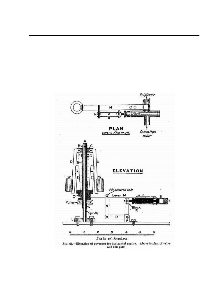
Making a Governor
It is a great advantage to have the engine
automatically governed, so that it may run at
a fairly constant speed under varying loads
and boiler pressures.
In the absence of a governor one has to be
constantly working the throttle; with one
fitted, the throttle can be opened up full at the
start, and the automatic control relied upon to
prevent the engine knocking itself to pieces.
The vertical centrifugal apparatus shown in
Fig. 66 was made by the writer, and acted
very well. The only objection to it is its
displacement of the pump from the bed. But a
little ingenuity will enable the pump to be
driven off the fly wheel end of the crank shaft,
or, if the shaft is cut off pretty flush with the
pulley, off a pin in the face of the pulley.
Turning to Fig. 66, A is a steel spindle fixed
in a base, L, screwed to the bed. B is a brass
tube fitting A closely, and resting at the
bottom on a 1/4-inch piece of similar tubing
pinned to A.
A wooden pulley jammed on B transmits
the drive from a belt which passes at its other
end round a similar, but slightly larger, pulley
on the crank shaft. This pulley is
accommodated by moving the eccentric
slightly nearer the crank and shortening the
fly-wheel side bearing a little.
The piece G, fixed to B by a lock screw, has
two slots cut in it to take the upper ends of
the weight links DD; and C, which slides up
and down B, is similarly slotted for the links
EE. Each of the last is made of two similarly
shaped plates of thin brass, soldered together
for half their length, but separated 3/32 inch
at the top to embrace the projections of D. To
prevent C revolving relatively to B, a notch is
filed in one side of the central hole, to engage
with a piece of brass wire soldered on B
(shown solid black in the diagram). A spiral
steel spring, indicated in section by a number
of black dots, presses at the top against the
adjustable collar F, and at the bottom against
C.
The two weights WW are pieces of brass bar
slotted for driving on to DD, which taper
gently towards the outer edge.
When the pulley revolves, centrifugal force
makes WW fly outwards against the pressure
of the spring, and the links EE raise C, which
in turn lifts the end of lever M. A single link,
N, transmits the motion from a pin on M to
the double bell-crank lever O (see Fig. 66)
Page 17
HORIZONTAL SLIDE-VALVE ENGINE
pivoted on a standard, P, attached to the
bedplate. The slotted upper ends of P engage
with pins on an adjustable block, R, which
moves the governing valve V (solid black),
working in the tube S through a gland. The
higher M is raised the farther back is V
moved, and its annular port is gradually
pushed more out of line with two ports in the
side of the valve tube, thus reducing the flow
of steam from the supply pipe to the cylinder
connection on the other side of the tube. This
connection, by-the-bye, acts as fulcrum for
lever M, which is made in two parts, held
together by screws, to render detachment
easy.
The closer the fit that V makes with S the
more effective will the governing be. The
gland at the end of S was taken from an old
cylinder cover.
Page 18

HORIZONTAL SLIDE-VALVE ENGINE
Regulation of the speed may be effected
either
(1) by driving the governor faster or slower
relatively to the speed of the crank
shaft;
(2) by altering the position of W on D;
(3) by altering the compression of the
spring by shifting F;
(4) by a combination of two or more of the
above.
Generally speaking, (3) is to be preferred, as
the simplest.
The belt may be made out of a bootlace or
fairly stout circular elastic. In either case the
ends should be chamfered off to form a
smooth joint, which may be wrapped
externally with thread.
FINAL HINTS
All parts which have to be fitted together
should have matching marks made on them
with the punch. To take the parts of the valve
chest as an example. As we have seen, these
should be soldered together, finished off
outside, and drilled. Before separating them
make, say, two punch marks on what will be
the upper edge of the valve plate near the
end, and two similar marks on the chest as
near the first as they can conveniently be. In
like manner mark the chest cover and an
adjacent part of the chest with three marks. It
is utterly impossible to reassemble the parts
incorrectly after separation if the marks are
matched. Marking is of greatest importance
where one piece is held up to another by a
number of screws. If it is omitted in such a
case, you may have a lot of trouble in
matching the holes afterwards.
Jacket the cylinder with wood or asbestos,
covered in neatly with sheet brass, to
minimize condensation. If the steam ways,
valve chest, and steam pipe also are jacketed,
an increase in efficiency will be gained,
though perhaps somewhat at the expense of
appearance.
Boiler
A vertical multi tubular boiler with about 800
sq. inches of heating surface will drive this
engine satisfactorily.
The Project Gutenberg EBook of Things To Make, by Archibald Williams
This project is for the use of anyone anywhere at no cost and with
almost no restrictions whatsoever. You may copy it, give it away or
re-use it under the terms of the Project Gutenberg License included
with this eBook or on line at www.gutenberg.net
Transcribed by David Lee ~ dslee@together.net
Page 19
Wyszukiwarka
Podobne podstrony:
Dark Horizons Universe Crisis on Sol Observatory
Horizons2tests
Horizons1tests
Vertical Horizontal Filter, giełda(3)
Horizontal Situation Indicator, Lotnicze różności
Parametric Horizontal? Trunnion Inch
HorizontalLines
06 Traz D'horizonte
EKSPLOZJA PLATFORMY WIERTNICZEJ DEEPWATER HORIZON, ochrona środowiska morskiego
grafo horizontal
Horizons Tests 3
Medical Miracles on the Horizon
HorizontalLines
Parametric Horizontal B inch
Solid Horizontal? Trunnion
Dark Horizons Universe Crisis on Sol Observatory
więcej podobnych podstron