
TOSHIBA
STORAGE DEVICE DIVISION
SD-R2002
CD-RW/DVD ROM DRIVE
PRODUCT SPECIFICATION
October 2000
REV. 1.0
Specifications are subject to change without notice
DOCUMENT NUMBER
14508

SD-R2002 Rev.1.0
Warnings:
This equipment (an optical disc drive) handled under the conditions out of equipment specifications
may cause heavy load, heat generation, malfunction, erroneous operation and performance degradation.
Therefore, please handle this equipment properly in compliance with the warnings provided below. In the
event that you do not comply with the warnings, Toshiba cannot guarantee the safety, reliability and
performance of the equipment expressly provided in the specification. Manufacturers and resellers
of the computer system using this equipment and/or this equipment itself shall notify the end-users of
the warnings provided herein and ensure them to comply with these warnings in an appropriate manner.
1. This equipment does not involve any over-current protection circuit. Use an appropriate over-current
protection in the computer system which this equipment would be connected. Toshiba shall not be
liable for any damages to the system which does not have any over-current protection.
2. DO NOT disassemble or modify this equipment. Toshiba shall not make any guarantee to the reliability,
safety and performance of this equipment expressly provided in the specification and nor be liable fo
r any damages resulting from such unauthorized disassembly or modification.
3. Read carefully and comply with this Product Specification in order to avoid the risk of data error in writing
operation. Such possible data error would be made by any factors other than this equipment (i.e., poor
storage media, misuse of this equipment, malfunction in a computer system connecting this equipment,
etc.). Toshiba shall not be liable for any damages resulting from such data loss. Check whether the
original data is correctly copied or stored upon completion of writing operation.
Take any necessary measures to protect your data such as system backup and/or mirroring disk
subsystems in order to avoid the risk of unexpected data loss or data corruption resulting from failure
in this equipment for some reasons.
Manufacturers and resellers of the computer system using this equipment shall be required to consider
the safety of such computer system and data integrity in order to avoid the risk of any consequential
damages caused by data loss or data corruption and any problems or accident caused by malfunction
of the computer system.
DO NOT use this equipment in the system such as medical equipment which may cause personal injury
or property damages resulting from malfunction of this equipment and unexpected data corruption or
data error in reading operation.
4. Turn off the power for this equipment and wait more than one (1) minute before you eject the disc using
the emergency eject mechanism when a disc cannot be ejected for some reasons in order to avoid the
risk of damages to the disc.
Notice
1. Turn off the system power before mounting/removing this equipment in order to avoid the risk of
damages to this equipment.
2. Insert the DC power plug in correct direction in order to avoid the risk of damages to this equipment.
3. Handle this equipment only in electrostatically safe environment and do not touch connecting terminals
with empty hands when you build in or pull out this equipment from other product in order to avoid the
risk of malfunction of this equipment.

SD-R2002 Rev.1.0
4.DO NOT do any of the following:
4.1. DO NOT use storage media (CD's / DVD's) that are not the correct size or shape, or do not meet the
minimum formatting requirements set forth in section 3.1.(1) of this Product Specification.
4.2. DO NOT insert more than one (1) CD or DVD disc into the drive at any time. Doing so will damage or
destroy this equipment and could damage or destroy the disc or cause data loss or corruption.
4.3. DO NOT load or eject any CD or DVD disc with force. Doing so will damage or destroy this equipment
and could damage or destroy the disc or cause data loss or destruction.
4.4. DO NOT give a strong shock while load or eject operation is in process. Doing so will damage or
destroy this equipment and could damage or destroy the disc or cause data loss or corruption.
4.5. DO NOT eject a CD or DVD disc while the drive is in operation. Doing so will damage or destroy this
equipment and could damage or destroy the disc or cause data loss or corruption.
4.6. DO NOT insert anything else into the drive other than a CD or DVD disc. Doing so will damage or
destroy this equipment.
-----
To OEM Customers:
-----------------------------------------------------------------
Please notify below notice to your customers.
Notice
Copyrighted works including, but not limited to music, video, computer program, database are
protected by copyright laws. Unless specifically permitted under applicable copyright laws,
you cannot copy, modify, assign, transmit or otherwise dispose of any copyrighted work
without the consent of the owner of the copyright.
Please take notice that unauthorized copying, modification, assignment, transmission and
other disposition may be subject to claims for damages and to penalties.

SD-R2002 Rev.1.0
Contents
1. Introduction ---------------------------------------------------------------------------------------------------------------------- 1
2. Features -------------------------------------------------------------------------------------------------------------------------- 1
3. Specifications ------------------------------------------------------------------------------------------------------------------ 3
3.1. Performance ------------------------------------------------------------------------------------------------------------ 3
3.2. Environmental Conditions ---------------------------------------------------------------------------------------- 5
3.2.1. Temperature and Humidity ---------------------------------------------------------------------------------- 5
3.2.2. Dust and Dirt ------------------------------------------------------------------------------------------------------ 5
3.2.3. Vibration ----------------------------------------------------------------------------------------------------------- 6
3.2.4. Atmospheric Pressure and Altitude -------------------------------------------------------------------- 6
3.2.5. Shock --------------------------------------------------------------------------------------------------------------- 6
3.3. Installation Conditions --------------------------------------------------------------------------------------------- 7
3.3.1. Equipment -------------------------------------------------------------------------------------------------------- 7
3.3.2. Installation --------------------------------------------------------------------------------------------------------- 7
3.4. Dimensions and Mass --------------------------------------------------------------------------------------------- 9
3.5. Reliabilities ------------------------------------------------------------------------------------------------------------- 9
3.5.1. Error Rate ---------------------------------------------------------------------------------------------------------- 9
3.5.2. MTBF ---------------------------------------------------------------------------------------------------------------- 9
3.5.3. MTTR ---------------------------------------------------------------------------------------------------------------- 9
3.5.4. Drive Life ----------------------------------------------------------------------------------------------------------- 9
4. Configurations -----------------------------------------------------------------------------------------------------------------10
4.1. Electrical Circuits ------------------------------------------------------------------------------------------------------10
4.2. Optical Pickup ---------------------------------------------------------------------------------------------------------10
4.3. Spindle Motor ----------------------------------------------------------------------------------------------------------10
4.4. Feed Motor --------------------------------------------------------------------------------------------------------------10
5. Functions ------------------------------------------------------------------------------------------------------------------------12
5.1. Disc Data Configurations ------------------------------------------------------------------------------------------12
5.1. 1. DVD-ROM Data Configurations ---------------------------------------------------------------------------12
5.1. 2.CD-ROM Data Configurations ------------------------------------------------------------------------------12
5.1. 3.CD-R/CD-RW Data Configurations -----------------------------------------------------------------------13
5.2. Power ON/OFF Timing --------------------------------------------------------------------------------------------14
6. Interfaces ------------------------------------------------------------------------------------------------------------------------14
6.1. I/O Cable ------------------------------------------------------------------------------------------------------------------14
6.2. Signal Summary -------------------------------------------------------------------------------------------------------15
6.2.1. Signal Specifications ----------------------------------------------------------------------------------------15
6.2.2. Timing of Host Interface (PIO) ----------------------------------------------------------------------------16
6.2.3. Timing of Host Interface (DMA Multi) -------------------------------------------------------------------17
6.2.4.Timing of Host Interface(Ultra DMA) ---------------------------------------------------------------------18
6.3. Connector -------------------------------------------------------------------------------------------------------------19
6.4. Support Command List --------------------------------------------------------------------------------------------19
7. Power Requirements -----------------------------------------------------------------------------------------------------21
7.1. Source Voltage
------------------------------------------------------------------------------------------------------21
7.1.1. Spike --------------------------------------------------------------------------------------------------------------21
7.1.2. Ripple
-----------------------------------------------------------------------------------------------------------21

SD-R2002 Rev.1.0
7.2. Current Drain
-------------------------------------------------------------------------------------------------------21
7.2.1.Sleep
------------------------------------------------------------------------------------------------------------21
7.2.2. Standby ----------------------------------------------------------------------------------------------------------21
7.2.3. Continuous Read
-------------------------------------------------------------------------------------------21
7.2.4. Idle ------------------------------------------------------------------------------------------------------------------21
7.2.5. Average ------------------------------------------------------------------------------------------------------------21
7.2.6. Maximum ----------------------------------------------------------------------------------------------------------21
7.2.7. Peak in executing Access ----------------------------------------------------------------------------------21
7.2.8. Write ----------------------------------------------------------------------------------------------------------------21
8. CD Audio
------------------------------------------------------------------------------------------------------------------- 22
8.1. Analog Out -----------------------------------------------------------------------------------------------------------22
8.2. Audio Modes ------------------------------------------------------------------------------------------------------- 22
9. Device Configuration Jumper ---------------------------------------------------------------------------------------- 22
9.1 Master Mode Setting ---------------------------------------------------------------------------------------------- 22
9.2 Slave Mode Setting ------------------------------------------------------------------------------------------------ 22
10.Busy Indicator
------------------------------------------------------------------------------------------------------------- 23
11. Emergency Release
-------------------------------------------------------------------------------------------------- 24
12. Safety Standards/Agency Approvals
--------------------------------------------------------------------------- 24
13. Electrostatic Discharge
---------------------------------------------------------------------------------------------- 24
14. Accessories
-------------------------------------------------------------------------------------------------------------- 24
15. Packaging
----------------------------------------------------------------------------------------------------------------- 25
16. CE Declaration of conformity
-------------------------------------------------------------------------------------- 25

1/27
SD-R2002 Rev.1.0
1. Introduction
This document describes TOSHIBA's SD-R2002 CD-RW/DVD-ROM Drive.
2. Features
This drive supports DVD CSS (Contents Scramble Systems) Disc.
This drive reads digital data stored on CD-ROM, DVD-ROM and CD audio discs.
This drive read and records the digital data on CD-R and CD-RW discs.
DVD-ROM disc spec (DVD-ROM Book) defines 120 mm and 80 mm in diameter, single and dual layers
as recording layer structure and single and double sides as recording side.
Maximum storage capacities are 4.38 GBytes and 15.9 GBytes for single layer/single side and
dual layer/double side respectively. (1 GByte=2
30
Bytes)
Due to these high capacity and high data transfer rate of 1352 KBytes/sec, DVD-ROM discs are
capable to store high quality and long duration MPEG-2 moving picture data. (1 KByte=2
10
Byte)
This drive reads digital stored on DVD-ROM discs at maximum 6 times faster rotational speed.
This drive reads digital stored on CD-ROM discs at maximum 24 times faster rotational speed.
This drive records (write once) digital data on CD-R disc at 2,4 times faster rotational speed.
This drive writes / rewrites digital data on CD-RW disc at 2,4 times faster rotational speed.
This drive writes / rewrites digital data on Hight-Speed CD-RW disc at 4 times faster rotational speed.
This drive offers long life and durability because the disc is written / read by a LASER, thereby eliminating
physical contact with the disc.
This drive supports SFF-8020i of ATAPI (ATA Packet Interface ) spec. ,SFF-8090 Ver.3 (Mt.Fuji3) of DVD
Commands and MMC of CD-R, CD-RW commands.
This drive shows a highest performance such as 60,000 hour MTBF.
This drive can be used in a vertical position or horizontal position.
This drive adopts RPC-II for its "Standard Specification Model".
Refer to the precation of the next page for the RPC-II.

2/27
SD-R2002 Rev.1.0
Matters to be attended to:
This drive adopts RPC Phase II
This CD-RW/DVD-ROM Drive adopts , the Phase II System of RPC (Regional Playback Control) , called
Phase II after here, on the basis of a contract with the CSS (Contents Scramble System) organization.
The CSS rule requires that all the products not only DVD Drives but also PC systems installing
DVD Drives sold from Jan.1, 2000 need to support Phase II described above.
To playback a DVD-Movie Software with the Regional Code specified by using a DVD Drive with Phase II
adopted, either the hardware or software used as applications on PC system side is also required to meet
Phase II.
In the combination of the drive and PC system with Phase II supported, as far as the Regional Code of a DVD-
Movie Software and the code memorized in the Phase II Specification Drive coincides, the Movie Software is
allowed to carry out.
In the Phase II Specification Drive, the region change by an end user is permitted up to 5 times in total
including the initial region set. After change to the fifth region is carried out, the Drive enters Parm State
(“no change allowed”status).
The drive with Parm State is permitted up to 4 times of "reinitialization" by a drive manufacturer or a specific
service center authorized by the CSS. Since it is considered that the reinitialization is carried out after the
completion of the region confirmation through test items in the PC manufacturer’s manufacturing line or the
completion of drive repair, etc., the number of reinitialization times may vary from 0 (no reinitialization
available) to 4 times. So, we recommend that not to disclose the reinitialization process to end users but only
to inform the number of region setting times as "end user’s direct region setting is available up to 5 times in
total."

3/27
SD-R2002 Rev.1.0
3. Specifications
3.1.Performance
(1) Applicable Write Format CD-R, CD-RW:
Disc at once, Track at once, Session at once, Packet write
(2) Applicable Write Disc *
1
CD-R, CD-RW:
CD-DA, CD+(E)G, CD-MIDI, CD-ROM,CD-ROM XA,
MIXED MODE CD, CD-I, CD-I Bridge (Photo-CD, Video-CD)
Multisession CD (Photo-CD, CD-EXTRA, Portfolio)
(3) Applicable Read Disc *
2
DVD:
DVD-ROM (DVD-5, DVD-9, DVD-10, DVD-18),
DVD-R
CD :
CD-DA, CD+(E)G, CD-MIDI, CD-TEXT, CD-ROM, ,
CD-ROM XA, MIXED MODE CD, CD-I,
CD-I Bridge (Photo-CD, Video-CD)
Multisession CD (Photo-CD, CD-EXTRA, Portfolio, CD-R,
CD-RW), CD-R, CD-RW
(4) Data Capacity
User Data/Block
DVD-ROM: 2,048 Byte/Block
CD-ROM : 2,048 Byte/Block (Mode 1)
2,336 Byte/Block (Mode 2)
Data Cpacity/Disc: (1 GB=2
30
Byte, 1 MB=2
20
Byte, 1 KB=2
10
Byte)
DVD- 5: 4.377 GB (4.700 Billion Byte)
DVD- 9: 7.959 GB (8.545 Billion Byte)
DVD-10: 8.754 GB (9.400 Billion Byte)
DVD-18: 15.917 GB (17.091 Billion Byte)
DVD-R : 3.679 GB (3.950 Billion Byte)
CD (Mode-1): 656.5 MB (688.4 Million Byte) *
3
CD (Mode-2): 748.8 MB (785.2 Million Byte) *
3
(5) Rotational Speed
DVD :
Approx. 3,792 rpm (2.5-6X CAV)
DVD-VIDEO (CSS Disc) :
Approx. 1,377-2,222 rpm (1.6-2.4X PCAV)
CD :
Approx. 5,100 rpm (10.3-24X CAV)
CD-RW, Video-CD,CD-DA :
Approx. 1,200 - 2,000 rpm (4-5.7X PCAV)
CD-R (Write):
Approx. 850 - 1,980 rpm (4X CLV)
Approx. 420 - 990 rpm (2X CLV)
CD-RW (Write):
Approx. 850 - 1,980 rpm (4X CLV)
Approx. 420 - 990 rpm (2X CLV)

4/27
SD-R2002 Rev.1.0
(6) Transfer Rate
( 1 KByte=2
10
Byte=1,024 Bytes, 1 MByte=2
20
Byte=1,048,576 Bytes)
Sustained Block Transfer Rate
DVD: 1,690-4,056 Block/s (2.5-6X CAV)
DVD-VIDEO (CSS Disc) : 1,082-1.622 Block/s (1.6-2.4X PCAV)
CD : 776-1,800 Block/s (10.3-24X CAV)
300-428 Block/s (4-5.7X PCAV)
Sustained Data Transfer Rate
DVD
: 3,357-8,112 KByte/s (2.5-6X CAV)
DVD-VIDEO (CSS Disc) : 1.6X-2.4X PCAV 2,163-3,245 KByte/s
CD
: (Mode 1) 4X-5.7X PCAV 600-855 KByte/s
10.3X-24X CAV 1,552-3,600 KByte/s
: (Mode 2) 4X-5.7X PACV 684.4-975.3 KByte/s
10.3X-24X CAV 1,769-4,104 KByte/s
Burst Data transfer Rate
16.7 MByte/s (PIO Mode 4 )
16.7 MByte/s ( Multi word DMA transfer mode-2)
33.3 MByte/s (Ultra DMA transfer mode-2)
(7) Access Time
Average Random Access Time
DVD:*
4
120 ms Typ
CD:*
5
110 ms Typ (10.3-24X)
Average Random Seek Time
DVD:*
6
115 ms Typ
CD:*
7
105 ms Typ (10.3-24X)
Average Full Stroke Access Time
DVD:*
8
180 ms Typ
CD:*
9
170 ms Typ (10.3-24X)
(8) Spin up Time ( Focus Search Time and Disc Motor Start up Time )
DVD:
2.5 s Typ
CD:
2.0 s Typ (10.3-24X)
(9) Data Buffer Capacity
2 MByte
*1: This drive write the data on the disc of CD-R, CD-RW format. However, in order to run applications that
use these formats you must first have the required software and/or hardware.
*2: All disc written in CD or DVD formats, except CD-DA (audio), require additional specific
application software and/or hardware. This drive referred in the specification is capable of reading
these data formats. However, in order to run applications that use these formats you must first have the
required software and/or hardware.
*3: Data capacity when recording depends on the condition of the record and decreases from this
occasionally.
*4: Measured by performing multiple accesses which means reads of data blocks over whole area of the
media from 0 (h) block to 1E7725(h) (4.089 Billion Byte:87 % of total area) block more than 3000
times. Includes positioning, setting, latency time and ECC implementation time (if required).
*5: Measured by performing multiple accesses which means reads of data blocks over whole area of the
media from 00 min 02 sec 00 Frame to 60 min 01 sec 74 Frame (552.96 Million Byte:87 %
of total area at linear velocity of 1.3 m/s) more than 3000 times. Includes positioning, setting, latency
time and ECC implementation time (if required).

5/27
SD-R2002 Rev.1.0
*6: Measured by performing multiple seek which means seeks of data block over whole area of the media
from 0(h) block to 1E7725(h) block more than 3000 times.
Includes positioning, setting time which is same definition as HDD.
*7: Measured by performing multiple seek which means seeks of data block over whole area of the media
from 00 min 02 sec 00 Frame to 60 min 01 sec 74 Frame more than 3000 times. Includes positioning,
setting time which is same definition as HDD.
*8: Measured by performing maximum accesses which means reads of each data block of
0 (h) Frame and 1E7725(h) Frame alternately more than 100 times.
Includes positioning, setting, latency time and ECC implementation time (if required)
*9: Measured by performing maximum accesses which means reads of each data block of 00 min
02 sec 00 Frame and 60 min 01 sec 74 Frame alternately more than 100 times.
Includes positioning, setting, latency time and ECC implementation time (if required)
(10) Drawer Load/Release Load:
Manual
Release:
(a) Electrical Release (Release Button)
(b) Release by ATAPI command
(c) Emergency Release
(11) Air Flow
Not Required
(12) Acoustic Noise
40 dB (IEC 179 A weighted at 1 m)
(13) Power Supply
+5 V (details in Section 7)
3.2. Environmental Conditions
This drive should be used under the conditions listed below.
3.2.1.Temperature and Humidity
(1) Operating Temperature
5
°
C
to 45
°
C
(2) Storage Temperature
-10
°
C
to 60
°
C
(3) Shipping Temperature
-40
°
C
to 65
°
C
*1
(4) Operating Temperature Gradient
11
°
C
/hour (max)
(5) Storage Temperature Gradient
20
°
C
/hour (max)
(6) Shipping Temperature Gradient
20
°
C
/hour (max) *1
(7) Operating Humidity
8 % to 80 %
(8) Storage Humidity
5 % to 95 %
(9) Shipping Humidity
5 % to 95 % *1
(10) Wet bulb Maximum Temperature
27
°
C
(11) Condensation
In all the above conditions there must be no condensation
*1: Packed in Toshiba original shipping package.
3.2.2.Dust and Dirt
unspecified

6/27
SD-R2002 Rev.1.0
3.2.3.Vibration
(1) Operating (CD 10.3-24X Read) (1 Oct/min) ---------------- no hard error
-----
5 to 500 Hz 2.45 m/s
2
[0.25 G] (
0-p)
(excluding resonance point)
(2) Operating (Write) (1 Oct/min) ---------------- no hard error
-----
5 to 500 Hz 2.45 m/s
2
[0.25 G] (
0-p)
(excluding resonance point)
(3) Non-operating (1 Oct/min) --------- no damage -----
5 to 10 Hz 5 mm
(p-p)
10 to 500 Hz 9.8 m/s
2
[1 G]
(0-p)
(4) Shipping (Packaged) (1 Oct/min) -----
no damage -----
10 to 25 Hz 9.8 m/s
2
[1G]
(0-p)
X Y Z/30 min each
3.2.4.Atmospheric Pressure and Altitude
(1) Operating
0 to 3,000 m
(2) Shipping
0 to 12,000 m
3.2.5.Shock
(1) Operating (Read ) --------------------
no hard error
---------------
14.7 m/s
2
[1.5 G] (Horizontal)
(Half sine wave 11 ms/10 s interval)
------------------------
no data loss --------------
98 m/s
2
[10 G]
(Half sine wave 11 ms/10 s interval)
(2) Operating (Write) ------------------------
no error --------------
14.7 m/s
2
[1.5 G] (Horizontal)
7.8 m/s
2
[0.8 G] (Vertical)
(Half sine wave 11 ms/10 s interval)
(3) Non-operating (with no Disc mounted) ----- no damage -----
490 m/s
2
[50 G]
(Half sine wave 11 ms)
(4) Drop (Packaged)
-------------------
no damage -----
(a) Bulk Package (50 pcs)
1 drop at 0.4 m (Bottom side only)
(b) Bulk Package (20 pcs)
0.6 m drops once for each 6-surface, 1-edge and 1-corner
7/27
SD-R2002 Rev.1.0
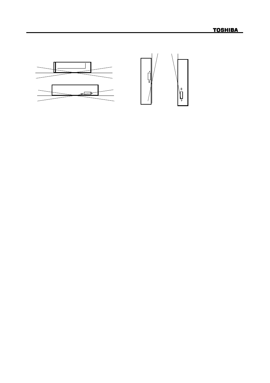
3.3. Installation Conditions
15
°
30
°
15
°
15
°
15
°
15
°
15
°
15
°
15
°
15
°
Figure 1 Mounting angle
3.3.1. Equipment
(1) When mounting the equipment, use four M2-P0.4 tapping holes located on the left and right
sides of the equipment.
(2) The opposite surface of the bearing surface (fitting surface when mounting) of the tapping
holes must be kept flat so that the bearing surface can be fit evenly.
(3) Use the mounting screws which do not enter deeply inside the equipment more than
specified value.
(4) When mounting the equipment, the tightening torque of four screws must be even.
The recommended screw tightening torque is 0.2 Nm.
3.3.2.Installation
(1) The mounting surface of the equipment must keep good flatness.
When mounting, care should be paid that an excessive force which may caused torsional
distortion on the equipment does not apply to the equipment. The recommended surface
flatness for the mounting surface should be less than 0.2 mm.
(2) Install the equipment with enough space as much as possible in all directions around the
equipment. Care should be paid that the equipment does not touch with peripheral
instruments even if vibration, mechanical shock, etc. are applied to the equipment.
For the maximum dimension of the equipment thickness (12.9 mm), it is recommended that a
clearance more than 0.5 mm should be left the thickness direction.
For the clearance around the front bezel, it is recommended that the clearance more than
0.8 mm should be left in all directions.
(3) Care should be especially paid for the heat effect. Keep the air ventilation and isolate from
heat of the environmental condition. Then, install the equipment where the
environmental temperature at the bottom center of cabinet does not exceed 45
°
C
.
8/27
SD-R2002 Rev.1.0
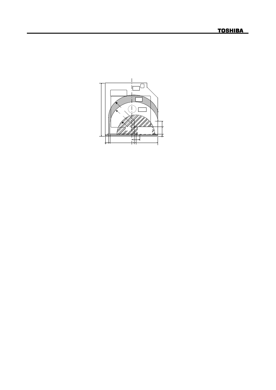
(4) Do not add the force beyond the indicated force on the top and bottom cover of the
equipment. (The restricted force range for the top cover is shown in the Figure 2.)
(For the bottom cover, the applied force should be less than 2N on whole area.)
1
29
7
11
6
4
7
0
7
4
1
28
20
5.4
24
37
2 N
R63
R59
R46
1 N
0.5 N
Do not add
the force
Figure 2 Restricted force range applied for the top cover
(5) The characteristics of EMC (Electro Magnetic Compatibility) are primarily influenced by the
mounting method of this equipment. Attach this equipment by considering an appropriate
method and structure.
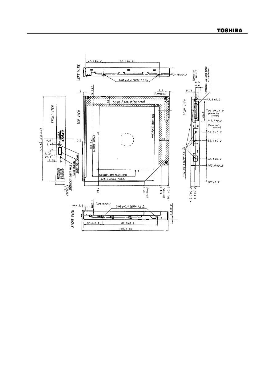
3.4. Dimension and Mass ----- See Figure 3 for details -----
(1) External Dimensions (W x H x D)
128 mm x 12.7 mm x 126.1 mm (excluding bezel)
(2) Mass
0.246 k
g
(Net)
353 k
g
(Bulk Packaged 50 pcs)
221 k
g
(Bulk Packaged 20 pcs)
9/27
SD-R2002 Rev.1.0
( Unit: mm )
Figure 3 External Dimensions

10/27
SD-R2002 Rev.1.0
3.5. Reliabilites
3.5.1. Error Rate
(1) Hard Read Error Rate (Byte Error Rate) ----- Allowing 5 Retries(default) -----
DVD:
10
-15
Max
CD:
Mode 1:10
-15
Max
Mode 2:10
-12
Max
(2) Seek Error Rate --- Allowing 10 Retries
10
-6
Max
(default)
3.5.2. MTBF
60,000 h
Assumptions: Power On Hours
5,436 h/year
On/Off Cycles
313 cycles/year
Number of Access
600,000 accesses/year
Operating Duty Cycle (Read)
20 % of Power On Time (Reading/Seeking)
Operating Duty Cycle (Write)
2 % of Power On Time (Writing/Seeking)
3.5.3. MTTR
0.5 h
3.5.4. Drive Life
15,000 h or 5 years (earlier one)
(1) Drawer Load/Release
10,000 times or more
(2) Interface connector Attach/Detach
500 times or more
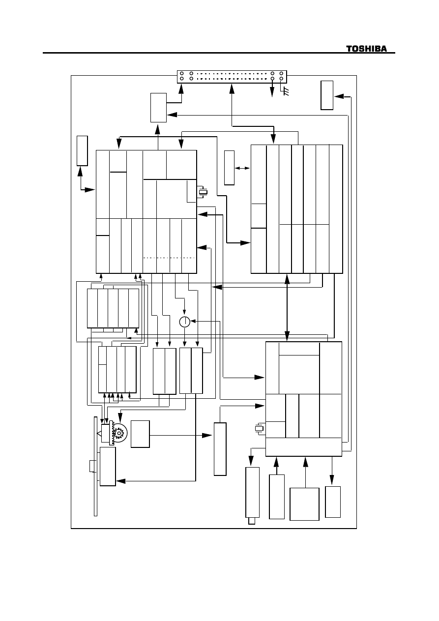
4. Configuration
See Figure 4 for details of the configurations
4.1. Electrical Circuits
(1) Drawer Release Switch and Release Detection Switch
(2) Optical Pickup Servo Drive Circuit
(3) Feed Motor Drive Circuit
(4) Laser Diode Control Circuit
(5) 8-16 Modulated data Demodulator, Error Correction Circuit and CSS Descrambler (DVD)
(System Control Circuit, Digital to Analog Converter)
(6) EFM Demodulator, Error Correction Circuit and DA converter (CD)
(7) IDE/ATAPI Control and CD-ROM Error Correction Circuit and Copy Protect Circuit (DVD)
(8) BCA Decoding Circuit
(9) CIRC Encoder
(10) EFM Encoder
(11) ATIP Demodulator
(12) Disc Moter Control Circuit
4.2. Optical Pickup
1-Lens and 2-Laser System
4.3. Spindle Motor
Brushless DC Motor
4.4. Feed Motor
DC Motor
11/27
SD-R2002 Rev.1.0
C
D-R
W / DVD-ROM DRIVE MODEL
SD-R2002 BLOCK DIAGRAM
D
isc Motor
P
UH
F
eed Motor
P
osition
Detector
R
F
Amp
E
QL
T
racking
Amp
F
ocus
Amp
T
A1323F
P
ower Driver
P
ower Driver
T
PIC1318
P
ower Driver
P
ower Driver
C
omparator
D
ata Slicer
T
C94A03
P
LL
D
-RAM Interface
D
emodulator
D
e-Scramble
E
CC
E
DC
A
/D
C
onverter
D
/A
D
/A
D
/A
D
/A
T
rack EQL
F
ocus EQL
F
eed EQL
D
isc EQL
M
emory Controller
S
ervo
Controller
C
lock
A
udio
D/A
D
igital
Audio
Decoder
D
RAM (1M)
M
uting
C
ommand Dec.
D
RAM (16M)
S
ync/ID Detect
C
lock
D
-RAM Interface
A
TIP
Demodulator
H
eader detect
E
rror Correct
IDE /
A
T
API Interface
D
igital
Audio Encoder
2
2.58 MHz
R
C5E839
F
G
B
CA
Decoder
C
D Encoder
+
5V
B
H6526FV
C
L
V Controller
A
TIP
Decoder
W
rite Strategy
F
ocus
Amp
T
racking
Amp
L
aser Control
C
ommad DCC
A
TIP
Filter
A
K8570
C
SS
Authenticator
G
P
IO
L
E
D
C
onverter
F
V
R
elease Solenoid
R
elease
S
witch
D
rawer
R
elease
D
etector
T
imer
Int.
C
ontrol
R
AM
M
icro
P
rocessor
C
D-BUS Interface
F
LASH ROM
6
3F49E
3
3.86 MHz
BUS Control
Clock
R
egulator
M
M3067
Figure 4 Configuration
12/27
SD-R2002 Rev.1.0
5.Functions
5.1. Disc Data Configurations
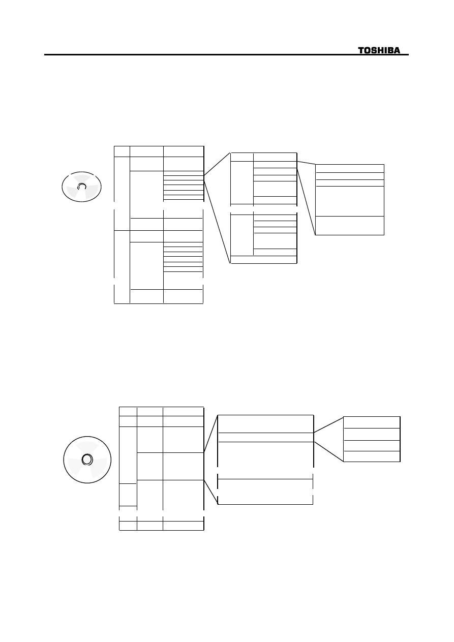
5.1.1. DVD-ROM Data Configurations
Figure 5 shows how data is constructed in the case of dual layer/parallel track data DVD disc.
The DVD spec defines the single layer, the dual layer/opposite and parallel track disc, that the
DVD-ROM drive supports. For details refer to DVD Book Part 1.
1 block=1/676 s
ID Data (Dual layer Parallel track path)
0
1
Lead-in
Area
1 - Disc
ECC Block 1
2
3
4
5
6
2
3
4
6
5
Approx. 130 k
ECC Block
ID No.
xxh - 2FFFFh
xxh - 2FFFFh
ID Data(4B)
ID Data EDC(2B)
Reserved (6B)
Main Data
(2048B)
nnnn
EDC (4B)
EDC(4B)
nnnn+15
ECC(160B)
Sector Format Type
Tracking Method
Refectivity
Area Type:
Data Area
Lead-in Area
Lead out Area
ECC Block 1
Lead-out
Area
Data
Area
ID No.
ID Data(4B)
ID Data EDC(2B)
Reserved (6B)
Main Data
(2048B)
Layer
No.
Data
Area
Lead-in
Area
Approx. 130 k
ECC Block
Lead-out
Area
Layer Number:
Layer 0
Layer 1
Information
~
~
~
~
~
~
~
~
Figure 5 DVD-ROM Disc Data Configuration
5.1.2. CD-ROM Data Configurations
Figure 6 shows how the data is structured in program units
1 block=1/75 s
Time
TNO
TOC
0
Lead-in
Min
Sec
Block
Block 1
Min
Sec
Block
1
Block 2
2
approx.
300 k-Blocks
AA
Lead out
1-Disc
Header
Minutes
Second(0~59)
Blocks(0~74)
Mode
4 bytes
User Data
2048 bytes in Mode-1
2336 bytes in Mode-2
ECC (Mode-1)
288 bytes
SYNC
12 bytes
~
~
~
~
~
~
~
~
Figure 6 CD-ROM Disc Data Configuration
13/27
SD-R2002 Rev.1.0
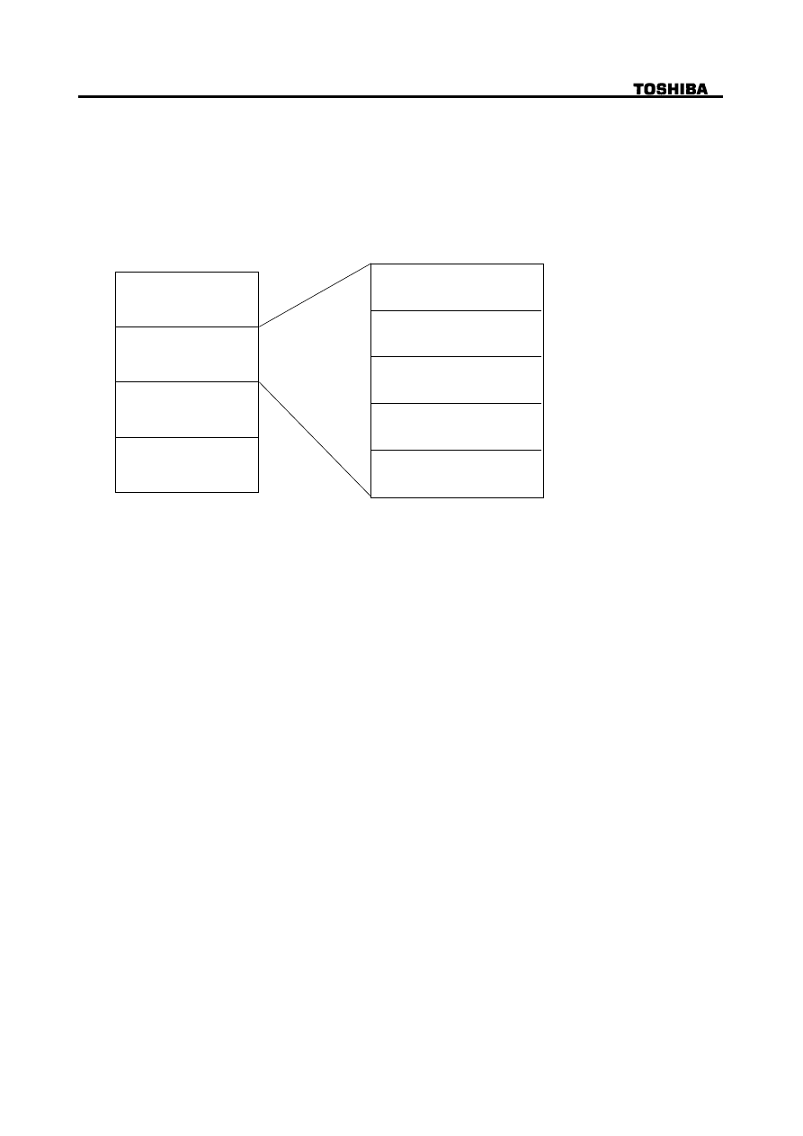
5.1.3. CD-R / CD-RW Data Configurations
Before writing
CD-R / CD-RW disc contains time-code information called ATIP.
ATIP is abbreviation of "Absolute Time In Pre-groove" in the wobbling groove by modulating
the carrier frequency.
(Address information is pre-formatted to ATIP on the CD-R / CD-RW disc and method for the
guide groove to wobble by FM modulation.)
Figure 7 shows the composition of ATIP.
Address
(n-1)
n
n+1
n+2
Address
Address
Address
Synchronization
Min
Sec
Frame
CRC
(4 bit)
(8 bit)
(8 bit)
(8 bit)
(14 bit)
Figure 7 CD-R / CD-RW Disc ATIP Data Configuration
After Writing
Data are written in CD format synchronizing with ATIP.
14/27
SD-R2002 Rev.1.0
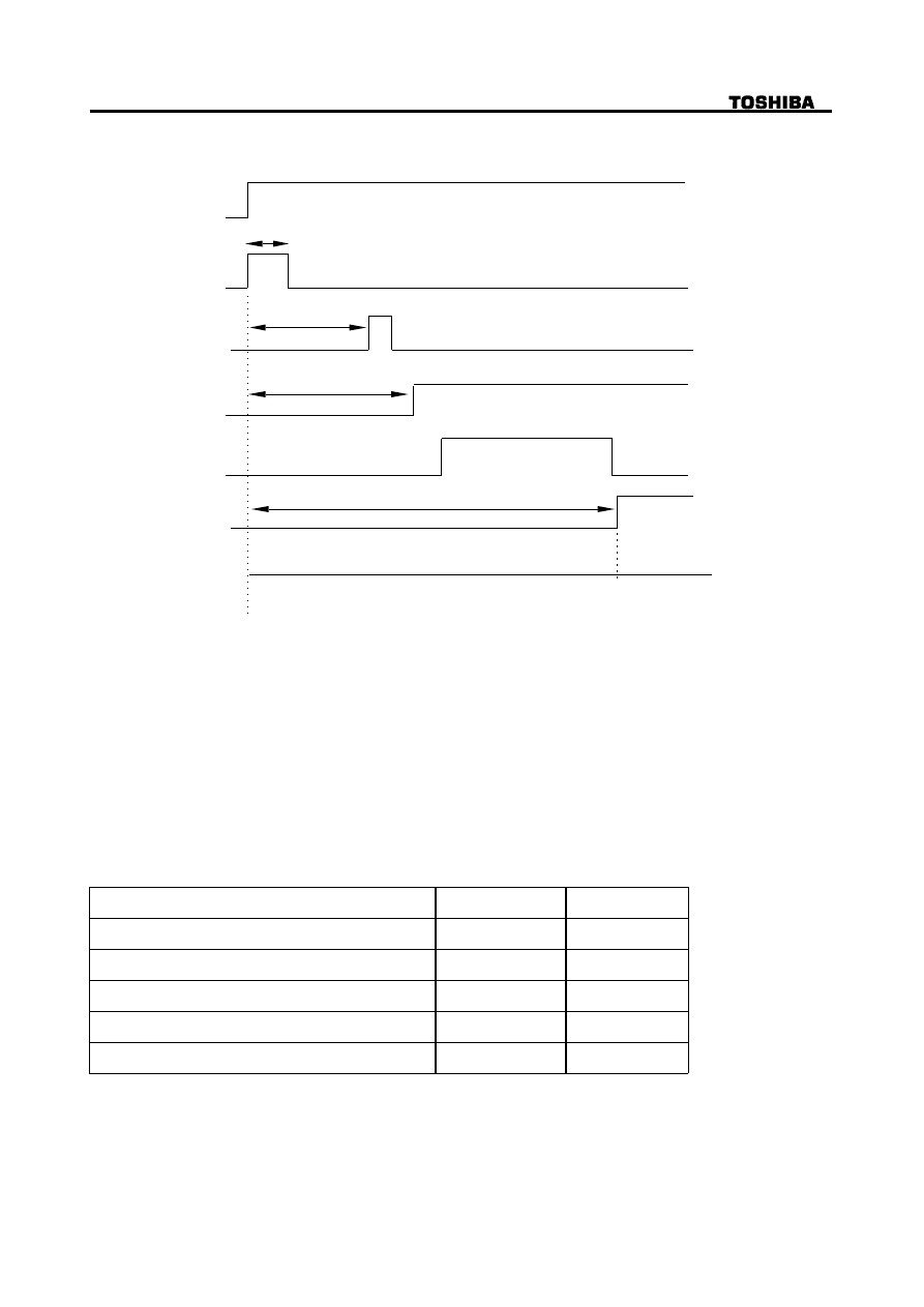
5.2. Power ON/OFF Timing
Figure 8 shows the initialization sequence
Power ON or
ATAPI-RST
System
Initialization
Focus Search
Spindle ON
Learning
Stand-by
"TEST UNIT
READY"
Command
"Command" Receivable
"Check Condition" Status
"Good" Status
Max. 550 ms
Max. 4 s
Max. 5 s
CD:Typ. 12 s, DVD 2 Layer Typ. 8 s, Max.60 s
(Single Session Disc)
"Read-Command"
Acceptable
Figure 8 Initialization Sequence
6. Interface
(1) The interface is based on X3T13/D96153 Revsion 18 (Mar. 18, 1997), SFF-8020i (Small Form
Factor Committee Specification of ATA-Packet Interface for CD-ROMs) Revision2.6 (Nov. 27, 1995),
SFF-8090 Ver.3, Rev.1.00 ('99-2-10).
(2) 64 (ATAPI, ATA) commands are usable.
(3) The 2 MByte data buffer handles both high speed and low speed data transmission.
(4) The largest block size on playback is 2,647 Bytes.
The data length for each block is changeable by command.
6.1. I/O cable
Table1 shows the cable parameters.
Min
Max
Cable length
0.46 m
Driver IoL sink current for 5 V operation
12 mA
Driver IoL sink current for 3.5 V operation
8 mA
Driver IoH sink current
-400
µ
A
Driver capacitive loading
25 pF
Table 1 Cable parameters
15/27
SD-R2002 Rev.1.0
6.2.Signal summary
The physical interface consists of single ended TTL compatible receivers and drivers
communicating through a 50P-connector as shown in Figure 13 and Figure 14 "Interface connector".
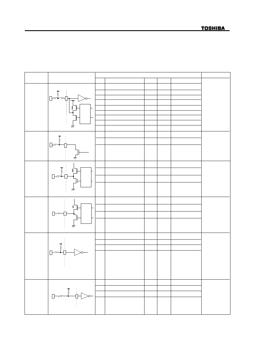
6.2.1. Signal Specification
Figure 9 shows the Signal Specifications
N
P
N
Sig. Name
HD0 - HD15
/DASP
/PDIAG
Type
Bidirectional
IOL
Driver sink current
Min
Max
24 mA
VOH Voltage Output High
Vdd-0.4 V
VOL Voltage Output Low
0.4 V
IOH=1 mA
IOL=12 mA
VIH
Input HIGH Voltage
2.4 V
TTL
VIL
Input LOW Voltage
ILI
-30 µA -400 µA
TTL
Pullup Resistor(Ri)
ILO
Input leakage Current
Output Leakage Current
Pullup Resistor(Ri)
CI
Input Capacitance
15 pF
CO
Output Capacitance
15 pF
Open Drain
/IOCS16
24 mA
VOL
Voltage Output Low
0.5 V
IOL=12 mA
CO
Output Capacitance
Driver sink current
P
N
Receivers/Drivers Caracteristics withoutExternal pullup Resistor
Condition
Rx
NOTE
Rs1=0 OHM
Rs2=33 OHM
HD0-HD15
Rx=10 kOHM
Rs1=0 OHM
Rs2=0 OHM
/PDIAG,
/DASP
IOL
IORDY
IOL
Driver sink current
24 mA
VOH Voltage Output High
VOL
Voltage Output Low
0.5 V
IOH=400 µA
IOL=12 mA
CO
Output Capacitance
/HDRQ
/INTRQ
P
N
IOL
Driver sink current
24 mA
VOH Voltage Output High
VOL
Voltage Output Low
0.4 V
IOH=400 µA
IOL=12 mA
CO
Output Capacitance
/HWR
/HRD
HA0 - HA2
/HCS1/HCS3
/HDAK
VIH
Input HIGH Voltage
2.0 V
TTL
VIL
Input LOW Voltage
ILI
-30 µA -400 µA
TTL
Pullup Resistor(Ri)
Input leakage Current
CI
Input Capacitance
Rx
RESET
100 kOHM
VIH
Input HIGH Voltage
2
.
4 V
VIL
Input LOW Voltage
ILI
-30 µA -400 µA Pullup Resistor(Ri)
Input leakage Current
CI
Input Capacitance
Rs
Rs
Rs
Rs=22 OHM
/INTRQ
/HDRQ
Rs=0 OHM
Rs
Rs=22 OHM
0.6 V
0.8 V
0.6 V
timing
control
timing
control
timing
control
2.4 V
Rs1
82 OHM
Rs2
Rx=infinity
Rx=infinity
Rs=82 OHM
/HWR, /HA0-2,
/HDAK
Rx=infinity
Rs=120 OHM
/HRD
Rx=10 kOHM
Rs=82 OHM
/HCS1,/HCS3
Vdd-0.4 V
-30 µA -400 µA
15 pF
15 pF
15 pF
15 pF
15 pF
Rx
Rx
Rx=1.2 kOHM
Rx=1 kOHM
Figure 9 Signal Specifications
16/27
SD-R2002 Rev.1.0
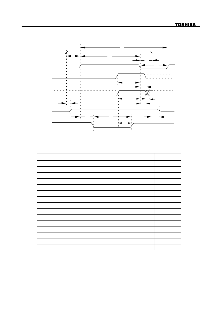
6.2.2.Timing of Host Interface (PIO)
Figure 10 shows the Host Interface Timings
t1
t4
Address valid*1
DIOR-/DIOW-*1
Write data valid*1
t6
t7
Read data valid*1
IOCS16-*1
t8
IORDY
tRD
t6Z
t9
tA
tB
t2i
t3
t5
t0
t2
*1: In all timing diagrams, the low line indicator negated, and the upper line
indicators asserted.
PIO timing parameters min (ns) max (ns)
Min Time (ns)
Max Time (ns)
t0
Cycle time
120
t1
Address valid to DIOR/DIOW-setup
25
t2
DIOR/DIOW-pulse wide
70
t2i
DIOR/DIOW-recovery time
25
t3
DIOW-data setup
20
t4
DIOW-data hold
10
t5
DIOR-data setup
20
t6
DIOR-data hold
5
t6Z
DIOR-data tristate
30
t7
Addr valid to IOCS 16-assertion
30
t8
Addr valid to IOCS 16-negation
30
t9
DIOR/DIOW-to address valid hold
10
tRD
Read Data Valid to IORDY active
0
tA
IORDY setup
35
tB
IORDY pulse wide
1250
Figure 10 Host Interface Timing (PIO Mode4)
17/27
SD-R2002 Rev.1.0
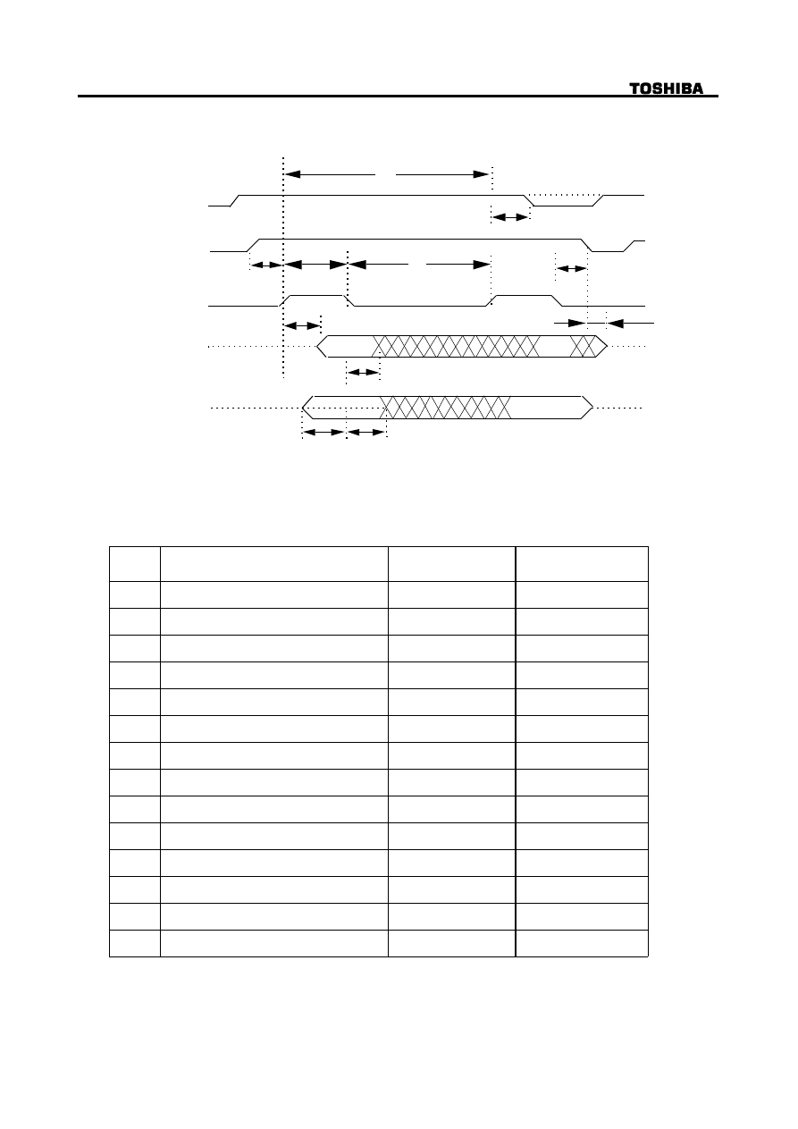
6.2.3.Timing of Host Interface (DMA Multi)
Figure 11 shows the Host Interface DMA multi word Timings
DMARQ
DMACK-*1
DIOR-/DIOW-*1
Read
DD0-15
Write
DD0-15
tZ
tI
tJ
tD
tE
tL
tF
tH
tG
t0
tK
*1: In all timing diagrams, the low line indicator negated, and the upper line
indicators asserted.
Multi word DMA
timing parameters min(ns) max(ns)
Min time
(ns)
Max time
(ns)
t0
Cycle time
120
tC
DMACK to DMREQ delay
---
tD
DIOR-/DIOW-16-bit
70
tE
DIOR- data access
---
tF
DIOR- data hold
5
tZ
DMACK- to tristate
25
tG
DIOR/DIOW- data setup
20
tH
DIOW- data hold
10
tI
DMACK to DIOR-/DIOW- setup
0
tJ
DIOR-/DIOW- to DMACK hold
5
tKr
DIOR- negated pulse width
25
tKw
DIOW- negated pulse width
25
tLr
DIOR- to DMREQ delay
35
tLw
DIOR- to DMREQ delay
35
Figure 11 Host Interface Timing (Multi Word DMA Mode 2)
18/27
SD-R2002 Rev.1.0
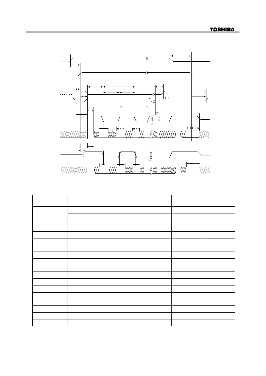
6.2.4.Timing of Host Interface (Ultra DMA )
Figure 12 shows the Host Interface Ultra DMA word Timings
DMARQ
DMACK-
STOP
DMARDY
STROBE
tMLI
tUI
tACK
tFS
tENV
tZAD
tZIORDY
t2CYC
tRP
tRFS
tLI
tACK
tDVS tDVH
CRC
tDVH
tDVS
tDVH
tDVS
tDVH
tDVS
tCYC
tCYC
DD (15:0)
Sender
STROBE
tZAD
tZIORDY
tDS
tDH
CRC
tDH
tDS
tDH
tDS
t D H
tDS
DD (15:0)
Recipient
t2CYC
In all timing diagrams, the low line indicator negated, and the upper line indicators asserted.
Ultra DMA Mode 2
Timing parameters min (ns) max (ns)
Min time (ns)
Max time (ns)
t2CYC
Typical Sustained Average Cycle time
120
Two cycle time (from rising edge to next rising edge of
from falling edge to next falling edge of STROBE)
117
tCYC
Cycle time allowing
55
tDVS
Data valid Setup time
34
tDVH
Data valid Hold time
6
tUI
Unlimited Interlock time
0
tACK
Setup and Hold Time for DMACK-
20
tENV
Envelope time
20
70
tZAD
Minimum Delay time for Driver
0
tZIORDY
Minimum time for DMACK-
20
tFS
First STROBE time
0
170
tRFS
Ready-to-Final STROBE time
50
tRP
Ready-to-Pause time
100
tLI
Limited Interlock time
0
150
tMLI
Interlock with minmum
20
tDS
Data setup time (at recipient)
7
tDH
Data hold time (at recipient)
5
Figure 12 Host Interface Timing (Ultra DMA Mode 2)
19/27
SD-R2002 Rev.1.0
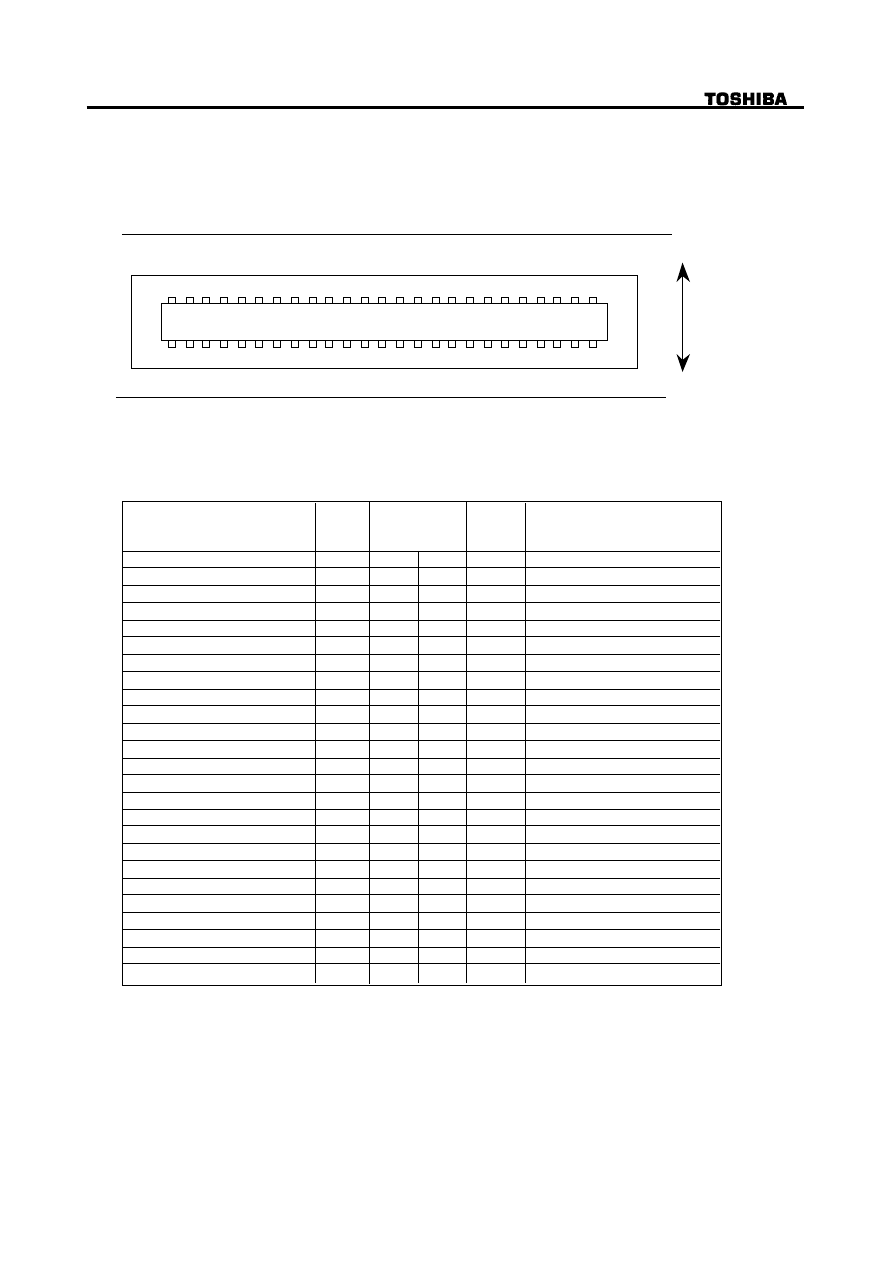
6.3. Connector
Figure 13 shows the connector and Figure 14 shows the interface pin assignments
Use Japan Aviation Electronics Industry Limited KX15-50KLD L or equivalent.
Conformable connector is Japan Aviation Electronics Industry Limited KX14-50 series.
DVD-ROM DRIVE REAR VIEW
1
3
5
7
9
1
1
1
3
1
5
1
7
1
9
2
1
2
3
2
5
2
7
2
9
3
1
3
3
3
5
3
7
3
9
4
1
4
3
4
5
4
7
4
9
2
4
6
8
1
0
1
2
1
4
1
6
1
8
2
0
2
2
2
4
2
6
2
8
3
0
3
2
3
4
3
6
3
8
4
0
4
2
4
4
4
6
4
8
5
0
TOP
BOTTOM
Figure 13 Connector pin assignments
Connector
contact
1
3
5
7
9
11
13
15
17
19
21
23
25
27
29
31
33
35
37
39
41
43
2
4
6
8
10
12
14
16
18
20
22
24
26
28
30
32
34
36
38
40
42
44
49
48
50
47
Vender unique*
Signal
name
Ground
DD8
DD9
DD10
DD11
DD12
DD13
DD14
DD15
Ground
DMARQ
/DIOR: /HDMARDT: HSTROBE
/DMACK
/IOCS16
/PDIAG
DA2
/CS3FX
Ground
+5 V(Motor)
Ground
Audio R-CH
Ground
+5 V(Logic)
+5 V(Motor)
Signal
name
Vender unique*
/RESET
DD7
DD6
DD5
DD4
DD3
DD2
DD1
DD0
Ground
Ground
Ground
/DIOW :STOP
IORDY: /DDMARDY: DSTROBE
INTRQ
DA1
DA0
/CS1FX
/DASP
+5 V(Logic)
Audio L-CH
+5 V(Motor)
Audio Ground
45
46
I/O
I/O
I/O
I/O
I/O
I/O
I/O
I/O
I/O
I/O
I
I
O
I
I
O
I
O
I
I
I
I/O
I
I
I
I/O
I/O
I/O
I/O
I/O
I/O
I/O
I/O
I/O
I
O
I
I
O
O
I
I
CSEL
I
A slash character(/) at the beginning of a signal name indicates it is asserted at the low level
(active low).
*Vender unique: Don't Connect (50 PIN)
*Vender unique: 49 PIN
Figure 14 Signal assignments
20/27
SD-R2002 Rev.1.0
6.4. Support Command List
ATAPI Packet Command for DVD-ROM Devices
00h
Test Unit Ready
01h
Rezero Unit
03h
Request Sense
12h
Inquiry
1Bh
Start / Stop Unit
1Ch
Receive Diagnostics
1Dh
Send Diagnostic
1Eh
Prevent / Allow Medium Removal
23h
Read Format Capacities
25h
Read Capacity
28h
Read (10)
2Bh
Seek (10)
42h
Read Sub-Channel
43h
Read TOC / PMA / ATIP
44h
Read Header
45h
Play Audio (10)
46h
Get Configuration
47h
Play Audio MSF
49h
Play Audio Track Relative (10)
4Ah
Get Event Status Notification
4Bh
Pause / Resume
4Eh
Stop Play / Scan
51h
Read Disc Information
52h
Read Track / RZone Information
55h
Mode Select (10)
5Ah
Mode Sense (10)
A2h
Send Event
A3h
Send Key
A4h
Report Key
A5h
Play Audio (12)
A8h
Read (12)
A7h
Set Read Ahead
A9h
Play Audio Track Relative (12)
ACh
Get Performance
ADh
Read DVD Structure
B6h
Set Streaming
B9h
Read CD MSF
BAh
SCAN
BBh
Set CD Speed
BDh
Mechanism Status
BEh
Read CD
42
43
44
45
46
47
48
49
No
OP Code
Command Description
3
4
5
6
7
8
9
10
11
12
13
14
15
16
17
18
19
20
21
22
23
24
25
26
27
28
29
30
31
32
33
34
35
36
37
38
39
40
41
1
2
04h
Format Unit
2Ah
Write (10)
35h
Flash Cache
53h
Reserve Track
5Bh
Close Track / Session
5Ch
Read Buffer Capacity
5Dh
Send Cue Sheet
A1h
Blank
21/27
SD-R2002 Rev.1.0
ATA Command for ATAPI DVD-ROM Devices
N o .
OP Code
Command Description
-
00h
Nop
1
08h
ATAPI Soft Reset
2
20/21h
Read Sector (s)
3
90h
Execute Drive Diagnostics
4
A0h
ATAPI Packet Command
5
A1h
ATAPI Identify Device
6
E0h
Standby Immediate
7
E1h
Idle Immediate
8
E2h
Standby
9
E3h
Idle
10
E5h
Check Power Mode
11
E6h
Sleep
12
ECh
ATA Identify Device
13
EFh
Set Feature
7. Power Requirements
7.1. Source Voltage
+5 V +/-5 % (Operating)
+5 V +/-8 % (Start up)
7.1.1. Spike
100 mV
(p-p)
Max.
7.1.2. Ripple
100 mV
(p-p)
Max.
7.2. Current Drain (Typical value)
+5 V
7.2.1.Sleep
40 mA (DVD/CD)
7.2.2.Standby (Laser off, Motor off)
140 mA (DVD/CD)
7.2.3. Continuous Read (Data/Audio)
780 mA (DVD 2.5-6X)
620 mA (CD 4-5.7X)
920 mA (CD 10.3-24X)
7.2.4.Idle (Laser on, Motor on)
560 mA (DVD 2.5-6X)
600 mA (CD 10.3-24X)
7.2.5. Average (20% Random Access)
740 mA (DVD 2.5-6X)
920 mA (CD 10.3-24X)
7.2.6. Maximum (100% Random Access)
800 mA (DVD 2.5-6X)
1,000 mA (CD 10.3-24X)
7.2.7. Peak in executing Access
1,650 mA (DVD/CD)
(Exclude Spike Current)
*Spike: Less than 1 ms of duration
7.2.8. Write (CD-R, CD-RW 4X)
760 mA (CD-R/RW)

22/27
SD-R2002 Rev.1.0
8.CD Audio (Test condition: Ordinary temperature)
8.1. Analog Out --- in case of the attenuator is set at 0 dB by the command ---
(1) Output Level
0.8 V (rms Typ)+/-1 dB
(2) Type
Unbalanced
(3) Load Impedance
47 kOHM min
(4) Frequency Response
20 Hz to 20 kHz+/-3.0 dB. (at 47 kOHM Load)
(5) Distortion
0.04 % Max. (at 1 kHz w/20 kHz LPF)
(6) Signal to Noise Ratio
80dB Typ (IEC179 A-Weighted)
8.2. Audio Modes
(1) 16 Modes including 'Stereo', 'Lch Mono', 'Rch Mono' and 'Mute' are selectable by command.
Default mode is 'Stereo'.
(2) 16 Steps of attenuation level for the Audio Output is selectable by command.
Default level is 0 dB.
9. Device Configuration Jumper
9.1. Master Mode Setting
Short-circuit the PIN 47 and PIN 48 of I/O connectors.
9.2.Slave Mode Setting
Open the PIN 47 of I/O connectors.
(Optional)
9.1. Master Mode Setting
Open the PIN 47 of I/O connectors.
9.2. Slave Mode Setting
Short-circuit the PIN 47 and PIN 48 of I/O connectors.
23/27
SD-R2002 Rev.1.0
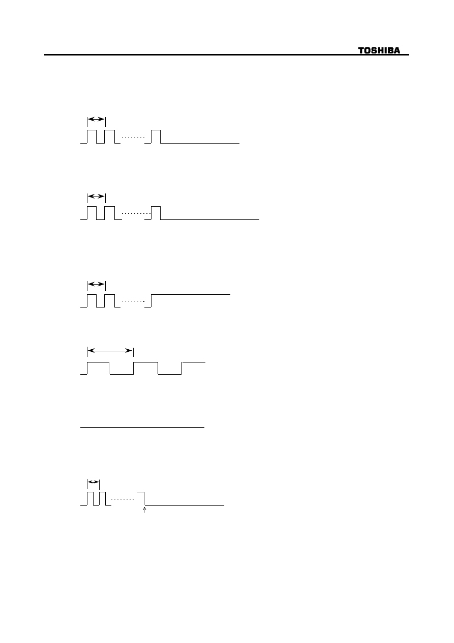
10. Busy Indicator
The LED at Front Bezel (Busy Indicator) indicates the drive status.
Color: AMBER
(1) After Drawer is closed, Busy Indicator start blinking at 0.8 s intervals, and then -----
(1-1) Turns off when the drive in the 'Idle' status.
0.8 s
Light Off
Figure 15 Idle
(1-2) Continuously off when no disc is mounted.
0.8 s
Light Off
Figure 16 No disc
(1-4) Continuously on when media has problem
0.8 s
Light On
Figure 17 Media Problem
(2) When playing an audio track, Busy Indicator is blinking at 1.6 s intervals.
1.6 s
Figurer 18 CD-Audio playback
(3) When performing 'Data Access' and during 'Data Transfer' and 'write' Busy Indicator keeps turn On.
Light On
Figurer 19 Data Access and Data Transfer
(4) When pushing Release button, Busy indicator is blinking at 0.4 s intervals.
0.4 s
Light Off
at the Release
Figurer 20 Release
24/27
SD-R2002 Rev.1.0
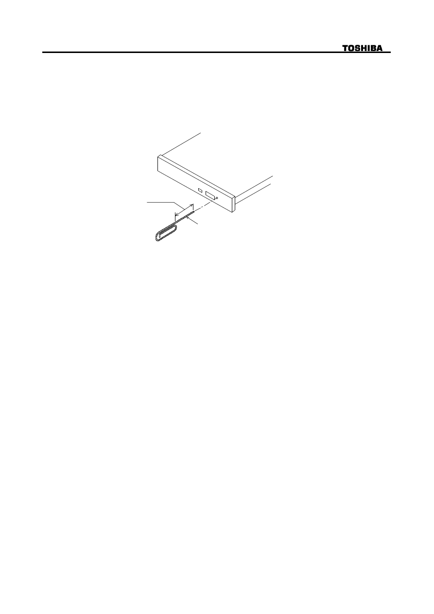
11.Emergency Release
Execute following procedure only in the case of emergency (Drawer will not release and disc
can not be removed although pressing Release Button).
(1) Turn the drive supplying power off.
(2) Insert solid bar (like paper clip) into Emergency Release hole and push as shown in Fig.21.
Then Drawer will be released.
(3) After removed the disc, gently push Drawer to close.
diameter 1.0 mm
15 mm
Figurer 21 Emergency Release
12.Safety Standards/Agency Approvals
(1) Safety
EN60950
UL 1950
CAN/CSA-22.2 No.950
(2) Laser
FDA 21CFR (U.S.A./DHHS)
EN60825-1 (Europe)
(3) EMC
CE
EN50081-1 (EMI)
: 1992 [Residential, commercial & light industry]
EN55022
: 1998 [Class B (domestic environment including]
EN55024 (EMS)
: 1998 [Information Technology equipment-
Immunity characteristices Limits and
methods of masurement]
IEC61000-4-2+A1 : 1995+1998 [CD:4 kV, ID: 4 kV, AD:8 kV]
IEC61000-4-3
: 1996 [3 V/m, 80-1000 MHz, 1 kHz 80 % AM ]
IEC61000-4-4
: 1995 [AC-line: 1 kV, I/F 0.5 kV
f: 5 kHz, Polarity: +/-]
IEC61000-4-5
: 1995 [AC-line: 2 kV/1 kV, Polarity: +/-]
IEC61000-4-6
: 1996 [3 V, 0.15-80 MHz, 80 % AM]
IEC61000-4-8
: 1993 [1 A/m, 50 Hz]
IEC61000-4-11
: 1994 [>95 % 0.5, 30% 25, >95 250]
KOREAN EMC No. 13237
TAIWAN EMI
CNS 13438
13. Electrostatic Discharge
Standard
IEC61000-4-2
(1) Operating
8 kV or less
(2) Damage including
15 kV or more
14. Accessories
None

25/27
SD-R2002 Rev.1.0
15. Packaging
(1) 50 units in a bulk package
24 bulk packs on one pallet.
* All transportation is allowed with pallet.
(Transportation with bulk package is not allowed.)
(2) 20 units in a bulk package
24 bulk packs on one pallet.
(Transportation with bulk package is allowed.)
(3) 1 unit in a bulk package
(Transporttation with bulk package is allowed.)
16. CE Declaration of conformity
Please refer to attached Annex 1.

26/27
SD-R2002 Rev.1.0
TOSHIBA
TOSHIBA EUROPE GMBH
EU-Declaration of Conformity
Product:
CD-RW/DVD-ROM Drive
Manufacturer(s):
Toshiba Corporation
1-1, Shibaura 1-chome, Minato-ku, Tokyo 105-8001 Japan
See page 2 for other locations
Model:
SD-R2002
Options:
None
Toshiba declares that the above mentioned product(s) with or without
the listed options comply to the EU-Directives and standards as listed on page 2.
Last two digits of the year in which the CE mark affixed : 00
Responsible for CE-marking:
Toshiba Europe GmbH
Signed by:
Mr. F.Yamashita, President of Toshiba Europe GmbH
Place:
D-41460 Neuss
Date:
August 16th, 2000
Signature:
----------------------------------------------------------
This declaration certifies compliance with the listed directives, but does not constitute an
assurance of characteristics.
The safety information in the supplied product documentation must be observed.
...........................................................................................................................................................
Document No.:
Y E A - R 2 2 2 2
P a g e :
1 of 2
............................................................................................................................................................
[History if issue]
Issued
: Aug. 11,2000
...................................................
Revision A
:
Ref.:
...................................................
.........................
Revision B
:
Ref.:
...................................................
.........................
Revision C
:
Ref.:
...................................................
.........................
Revision D
:
Ref.:
...................................................
.........................
TOSHIBA EUPOPE GMBH
HAMMFELODAMMB.D-41460NEUSS
GESCHAFTSUHRER
POSTFCH 101482. D-41414 NEUSS
HISATSUGU NONAKA
TELEFON: (02131) 158-01
HRB 3479 AMTSGERICHT NESS
TELFAX : (02131) 158-341
Annex 1
27/27
SD-R2002 Rev.1.0
EU-Declaration of Conformity
ED-Directive
Related Standard
Issude
Level/Test condition
EMC-emission:
EMC-immunity
Product/Options
Model
Related EU-Directive
89/336/EEC
X
Manufactuer(s) Location
Address
Page:
Revision:
EN55022 1998 Class B (domestic environment including)
EN50081-1 1992 Residential, commercial & light industry
EN55024 1998 Information Technology equipment-Immunity
IEC61000-4-2+A1 1995 +1998 CD: 4 kV, ID: 4 kV, AD: 8 kV
IEC61000-4-3 1996 3 V/m, 80-1000 MHz, 1 kHz 80 % AM
IEC61000-4-4 1995 AC-line: 1 kV, I/F 0.5 kV f: 5 kHz, Polarity: +/-
IEC61000-4-6 1996 3 V, 0.15-80 MHz, 80 % AM
IEC61000-4-8 1993 1 A/m, 50 Hz
IEC61000-4-11 1994 >95 % 0.5, 30% 25, >95 250
YEA-R2222
Document No.:
2 of 2
899/336/EEC
(EMC Directive)
IEC61000-4-5 1995 AC-line: 2 kV/1 kV, Polarity: +/-
Toshiba Multi Media Devices Co, Ltd 19 Minase, Fukihata Goshogawara-shi, Aomori 037-0003 Japan
CD-RW/DVD-ROM Drive
SD-R2002
characteristices Limits and methods of masurement

SD-R2002 Rev.1.0
Deviation List
P a g e
I t e m
R e v # 0 . 5
R e v # 1 . 0
Page
ahead of
contents Notice
-----
All of change
1
1. Introduction
-----
This drive writes / rewrites digital
data on Hight-Speed CD-RW disc
at 4 times faster rotational speed.
3
(4) Data Capacity
-----
Add *3
(5) Rotational Speed
CD-RW, Video-CD :
CD-RW, Video-CD,CD-DA :
4
(7) Access Time
Average Random Access Time
DVD: TBD ms Typ
DVD: 120 ms Typ
CD: TBD ms Typ
CD: 110 ms Typ
Average Random Seek Time
DVD: TBD ms Typ
DVD: 115 ms Typ
CD: TBD ms Typ
CD: 105 ms Typ
Average Full Stroke Access Time
DVD: TBD ms Typ
DVD: 180 ms Typ
CD: TBD ms Typ
CD: 170 ms Typ
(8) Spin up Time
DVD: TBD s Typ
DVD: 2.5 s Typ
CD: TBD s Typ
CD: 2.0 s Typ
Note
-----
Add *3 and * is changed by sending
at the following.
5
3.2.1.Temperature and Humidity
(1) Operating Temperature
5
°
C to 50
°
C (TBD)
5
°
C to 45
°
C
7
3.3.2.Installation
(3) Care should be.....
(3) Care should be.....
.....exceed 45
°
C.
.....exceed 45
°
C.
8
Figure 2
TBD
2 N, 1 N, 0.5 N
3.4. Dimension and Mass
(2) Mass
TBD k
g
(Net)
0.246 k
g
(Net)
TBD k
g
(Bulk Packaged 50 pcs)
353 k
g
(Bulk Packaged 50 pcs)
TBD k
g
(Bulk Packaged 20 pcs)
221 k
g
(Bulk Packaged 20 pcs)
9
Figure 3
-----
All of change
11
Figure 4
-----
Delete the 33.86 MHz
14
Figure 8
-----
Delete the TBD
6. Interface
(1) The interface is based on
(1) The interface is based on
X3T10/2008D Revision 6
X3T13/D96153 Revsion 18
(dated Oct. 26,1995) ,.....
(Mar. 18, 1997), .....
15
Figure 9
-----
Part of change

SD-R2002 Rev.1.0
P a g e
I t e m
R e v # 0 . 5
R e v # 1 . 0
21
7.2. Current Drain
7.2.1.Sleep
TBD mA (DVD/CD)
40 mA (DVD/CD)
7.2.2.Standby
TBD mA (DVD/CD)
140 mA (DVD/CD)
7.2.3. Continuous Read
TBD mA (DVD 2.5-6X)
780 mA (DVD 2.5-6X)
TBD mA (CD 4-5.7X)
620 mA (CD 4-5.7X)
TBD mA (CD 10.3-24X)
920 mA (CD 10.3-24X)
7.2.4.Idle
TBD mA (DVD 2.5-6X)
560 mA (DVD 2.5-6X)
TBD mA (CD 10.3-24X)
600 mA (CD 10.3-24X)
7.2.5. Average
TBD mA (DVD 2.5-6X)
740 mA (DVD 2.5-6X)
TBD mA (CD 10.3-24X)
920 mA (CD 10.3-24X)
7.2.6. Maximum
TBD mA (DVD 2.5-6X)
800 mA (DVD 2.5-6X)
TBD mA (CD 10.3-24X)
1,000 mA (CD 10.3-24X)
7.2.7. Peak in executing Access TBD mA (DVD/CD)
1,650 mA (DVD/CD)
7.2.8. Write
TBD mA (CD-R/RW)
760 mA (CD-R/RW)
24
12. Safety standard.....
(3) CE (TENTATIVE)
Tentative
Non-Tentative
26
Annex 1
Tentative
Non-Tentative
27
EU-Declaration of Conformity
Tentative
Non-Tentative
Wyszukiwarka
Podobne podstrony:
nagrywanie plyt cd i dvd leksyk Nieznany
nagrywanie plyt cd i dvd ilustrowany poradnik ebook promocyjny helion pl (nacdvd) NKY7C7ELZDCSFTCXEQ
Horiz deflect tranz toshiba
Toshiba Satellite Pro`50
Enter Service Toshiba
nagrywaczka id 313005 Nieznany
ABC nagrywania płyt DVD
Circuit diagram 21F2 Toshiba
Słowniczek Jak nagrywać? RW
Nagrywanie płyt? Podstawowe pojęcia
dvd nagrywarka
cdvdk2 7 nagrywanie plyt cd i dvd kurs wyd ii ebook promocyjny helion pl KITBJ4T5RRGTF67ZZFKX5K5G7OG
DVD Toshiba SD 2006 3006 dvd01f
nagrywanie płyt cd i dvd kurs APDRAKIZNTASMUQE4NS6CYGIACGVFND4RZDUKOQ
26 Podkręcanie Nagrywarki(bitnova info)
więcej podobnych podstron