
1081 VW Golf & Jetta
4A
Chapter 4 Part A:
Fuel and exhaust systems - carburettor models
Air cleaner
Type . . . . . . . . . . . . . . . . . . . . . . . . . . . . . . . . . . . . . . . . . . . . . . . . . . . .
Automatic air temperature control
Element type . . . . . . . . . . . . . . . . . . . . . . . . . . . . . . . . . . . . . . . . . . . . . .
Renewable paper
Element application:
1.05 litre . . . . . . . . . . . . . . . . . . . . . . . . . . . . . . . . . . . . . . . . . . . . . . .
Champion Wl01
1.3 litre . . . . . . . . . . . . . . . . . . . . . . . . . . . . . . . . . . . . . . . . . . . . . . . .
Champion W102
1.6 litre . . . . . . . . . . . . . . . . . . . . . . . . . . . . . . . . . . . . . . . . . . . . . . . .
Champion U508
1.8 litre . . . . . . . . . . . . . . . . . . . . . . . . . . . . . . . . . . . . . . . . . . . . . . . .
Champion U508
Fuel pump
Type:
1.05 and 1.3 litre . . . . . . . . . . . . . . . . . . . . . . . . . . . . . . . . . . . . . . . . .
Mechanical, diaphragm, operated by plunger from camshaft
1.6 and 1.8 litre . . . . . . . . . . . . . . . . . . . . . . . . . . . . . . . . . . . . . . . . . .
Mechanical, diaphragm, operated by eccentric on intermediate shaft
Fuel filter
Type . . . . . . . . . . . . . . . . . . . . . . . . . . . . . . . . . . . . . . . . . . . . . . . . . . . .
Champion L104
Carburettor - 1.05 litre
Pierburg/Solex 31 PIC-7
Type . . . . . . . . . . . . . . . . . . . . . . . . . . . . . . . . . . . . . . . . . . . . . . . . . . . .
Downdraught with manual or automatic choke
Venturi . . . . . . . . . . . . . . . . . . . . . . . . . . . . . . . . . . . . . . . . . . . . . . . . . . .
23 mm
Main jet . . . . . . . . . . . . . . . . . . . . . . . . . . . . . . . . . . . . . . . . . . . . . . . . . .
X117.5
Air correction jet with emulsion tube . . . . . . . . . . . . . . . . . . . . . . . . . . .
115 Z
Idling fuel jet . . . . . . . . . . . . . . . . . . . . . . . . . . . . . . . . . . . . . . . . . . . . . .
45
Idling air jet . . . . . . . . . . . . . . . . . . . . . . . . . . . . . . . . . . . . . . . . . . . . . . .
135
Auxiliary fuel jet . . . . . . . . . . . . . . . . . . . . . . . . . . . . . . . . . . . . . . . . . . . .
32.5
Auxiliary air jet . . . . . . . . . . . . . . . . . . . . . . . . . . . . . . . . . . . . . . . . . . . . .
130
Enrichment (primary/secondary) . . . . . . . . . . . . . . . . . . . . . . . . . . . . . . .
70/70
Injection capacity (cc/stroke) . . . . . . . . . . . . . . . . . . . . . . . . . . . . . . . . .
1.00 ± 0.15
Float needle valve . . . . . . . . . . . . . . . . . . . . . . . . . . . . . . . . . . . . . . . . . .
1.5
Float needle valve washer thickness . . . . . . . . . . . . . . . . . . . . . . . . . . .
2.0 mm
Fast idle speed . . . . . . . . . . . . . . . . . . . . . . . . . . . . . . . . . . . . . . . . . . . .
2600 ± 100 rpm
Choke valve gap . . . . . . . . . . . . . . . . . . . . . . . . . . . . . . . . . . . . . . . . . . .
1.8 ± 0.2 mm
Throttle valve gap smooth running detent . . . . . . . . . . . . . . . . . . . . . . .
2.5 ± 0.3 mm
Idle speed . . . . . . . . . . . . . . . . . . . . . . . . . . . . . . . . . . . . . . . . . . . . . . . .
950 ± 50 rpm
CO content % . . . . . . . . . . . . . . . . . . . . . . . . . . . . . . . . . . . . . . . . . . . . .
1.0 ± 0.5
Accelerator and throttle cables - removal, refitting and adjustment . 10
Accelerator pedal - removal and refitting . . . . . . . . . . . . . . . . . . . . . 11
Air cleaner element - renewal . . . . . . . . . . . . . . . . . . . . . . . . . . . . . . 2
Air cleaner unit - removal and refitting . . . . . . . . . . . . . . . . . . . . . . . . 3
Automatic air cleaner temperature control - testing . . . . . . . . . . . . . 4
Carburettor (1.05 litre engine) - adjustments . . . . . . . . . . . . . . . . . . . 15
Carburettor (1.3 litre engine) - adjustments . . . . . . . . . . . . . . . . . . . . 16
Carburettor (1.6 & 1.8 litre engines) - adjustments . . . . . . . . . . . . . . 17
Carburettor - overhaul . . . . . . . . . . . . . . . . . . . . . . . . . . . . . . . . . . . . 14
Carburettor - removal and refitting . . . . . . . . . . . . . . . . . . . . . . . . . . 13
Choke cable (1.05 litre engine) - removal, refitting and adjustment . 12
Exhaust system - inspection, removal and refitting . . . . . . . . . . . . . 20
Fuel filler gravity valve - removal, testing and refitting . . . . . . . . . . .. 9
Fuel gauge sender unit - removal and refitting . . . . . . . . . . . . . . . . . 8
Fuel pump - testing, removal and refitting . . . . . . . . . . . . . . . . . . . . . 5
Fuel reservoir - removal and refitting . . . . . . . . . . . . . . . . . . . . . . . . . 6
Fuel tank - removal and refitting . . . . . . . . . . . . . . . . . . . . . . . . . . . . 7
General information and precautions . . . . . . . . . . . . . . . . . . . . . . . . 1
Inlet and exhaust manifolds - removal and refitting . . . . . . . . . . . . . 19
Inlet manifold preheating - testing . . . . . . . . . . . . . . . . . . . . . . . . . . . 18
4A•1
Specifications
Contents
Easy, suitable for
novice with little
experience
Fairly easy, suitable
for beginner with
some experience
Fairly difficult,
suitable for competent
DIY mechanic
Difficult, suitable for
experienced DIY
mechanic
Very difficult,
suitable for expert DIY
or professional
Degrees of difficulty
5
4
3
2
1

Carburettor - 1.05 litre (continued)
Pierburg/Solex 1B3
Venturi . . . . . . . . . . . . . . . . . . . . . . . . . . . . . . . . . . . . . . . . . . . . . . . . . . .
23 mm
Main jet . . . . . . . . . . . . . . . . . . . . . . . . . . . . . . . . . . . . . . . . . . . . . . . . . .
105
Air correction jet . . . . . . . . . . . . . . . . . . . . . . . . . . . . . . . . . . . . . . . . . . .
57.5
Idling fuel/air jet . . . . . . . . . . . . . . . . . . . . . . . . . . . . . . . . . . . . . . . . . . .
50/130
Pump injection tube . . . . . . . . . . . . . . . . . . . . . . . . . . . . . . . . . . . . . . . .
32.5/150
Needle valve . . . . . . . . . . . . . . . . . . . . . . . . . . . . . . . . . . . . . . . . . . . . . .
1.5
Accelerator pump capacity (cc/stroke) . . . . . . . . . . . . . . . . . . . . . . . . . .
1.0 ± 0.15
Choke valve gap . . . . . . . . . . . . . . . . . . . . . . . . . . . . . . . . . . . . . . . . . . .
1.8 ± 0.2 mm
Fast idle speed . . . . . . . . . . . . . . . . . . . . . . . . . . . . . . . . . . . . . . . . . . . .
2000 ± 100 rpm
Idle speed . . . . . . . . . . . . . . . . . . . . . . . . . . . . . . . . . . . . . . . . . . . . . . . .
800 ± 50 rpm
CO content % . . . . . . . . . . . . . . . . . . . . . . . . . . . . . . . . . . . . . . . . . . . . .
2.0 ± 0.5
Weber 32 TLA
Venturi . . . . . . . . . . . . . . . . . . . . . . . . . . . . . . . . . . . . . . . . . . . . . . . . . . .
22 mm
Main jet:
Code 030 129 016 . . . . . . . . . . . . . . . . . . . . . . . . . . . . . . . . . . . . . . .
105
Code 030 129 016 D . . . . . . . . . . . . . . . . . . . . . . . . . . . . . . . . . . . . . .
102
Air correction jet:
Code 030 129 016 . . . . . . . . . . . . . . . . . . . . . . . . . . . . . . . . . . . . . . .
80
Code 030 129 016 D . . . . . . . . . . . . . . . . . . . . . . . . . . . . . . . . . . . . . .
100
Emulsion tube . . . . . . . . . . . . . . . . . . . . . . . . . . . . . . . . . . . . . . . . . . . . .
F96
Idling fuel jet . . . . . . . . . . . . . . . . . . . . . . . . . . . . . . . . . . . . . . . . . . . . . .
47
Idling air jet:
Code 030 129 016 . . . . . . . . . . . . . . . . . . . . . . . . . . . . . . . . . . . . . . .
110
Code 030 129 016D . . . . . . . . . . . . . . . . . . . . . . . . . . . . . . . . . . . . . .
145
Auxiliary fuel jet (code 030 129 016D) . . . . . . . . . . . . . . . . . . . . . . . . . .
30
Auxiliary air jet (code 030 129 016D) . . . . . . . . . . . . . . . . . . . . . . . . . . .
170
Pump injection tube . . . . . . . . . . . . . . . . . . . . . . . . . . . . . . . . . . . . . . . .
0.35/0.35
Needle valve . . . . . . . . . . . . . . . . . . . . . . . . . . . . . . . . . . . . . . . . . . . . . .
1.75
Needle valve washer thickness . . . . . . . . . . . . . . . . . . . . . . . . . . . . . . ..
0.75 mm
Accelerator pump capacity (cc/stroke) . . . . . . . . . . . . . . . . . . . . . . . . . .
1.05 ± 0.15
Choke valve gap (pull-down):
Without vacuum . . . . . . . . . . . . . . . . . . . . . . . . . . . . . . . . . . . . . . . . .
2.5 ± 0.2 mm
With 300 mbar vacuum . . . . . . . . . . . . . . . . . . . . . . . . . . . . . . . . . . . .
2.0 ± 0.2 mm
Choke valve gap (wide open kick):
Code 030 129 016 . . . . . . . . . . . . . . . . . . . . . . . . . . . . . . . . . . . . . . .
2.0 ± 0.5 mm
Code 030 129 01 6D . . . . . . . . . . . . . . . . . . . . . . . . . . . . . . . . . . . . . .
2.5 ± 0.5 mm
Float level . . . . . . . . . . . . . . . . . . . . . . . . . . . . . . . . . . . . . . . . . . . . . . . .
28.0 ± 1.0 mm
Fast idle speed . . . . . . . . . . . . . . . . . . . . . . . . . . . . . . . . . . . . . . . . . . . .
2000 ± 100 rpm
Idle speed . . . . . . . . . . . . . . . . . . . . . . . . . . . . . . . . . . . . . . . . . . . . . . . .
800 ± 50 rpm
CO content % . . . . . . . . . . . . . . . . . . . . . . . . . . . . . . . . . . . . . . . . . . . . .
2.0 ± 0.5
Carburettor - 1.3 litre
Pierburg/Solex 2E3
Type . . . . . . . . . . . . . . . . . . . . . . . . . . . . . . . . . . . . . . . . . . . . . . . . . . . .
Twin progressive choke, downdraught with automatic choke
Stage I
Stage II
Venturi . . . . . . . . . . . . . . . . . . . . . . . . . . . . . . . . . . . . . . . . . . . . . . . . . . .
19
23
Main jet . . . . . . . . . . . . . . . . . . . . . . . . . . . . . . . . . . . . . . . . . . . . . . . . . .
X95
X110
Air correction jet with emulsion tube . . . . . . . . . . . . . . . . . . . . . . . . . . .
120
130
Idling fuel/air jet . . . . . . . . . . . . . . . . . . . . . . . . . . . . . . . . . . . . . . . . . . .
45/130
-
Full throttle enrichment . . . . . . . . . . . . . . . . . . . . . . . . . . . . . . . . . . . . . .
-
95
Pump injection tube diameter . . . . . . . . . . . . . . . . . . . . . . . . . . . . . . . . .
0.35 mm
-
Choke cover code . . . . . . . . . . . . . . . . . . . . . . . . . . . . . . . . . . . . . . . . .
276
Injection capacity (cc/stroke) . . . . . . . . . . . . . . . . . . . . . . . . . . . . . . . . .
1.0 ± 0.15
Locking lever clearance . . . . . . . . . . . . . . . . . . . . . . . . . . . . . . . . . . . . .
0.4 ± 0.15 mm
Full throttle enrichment - height above atomiser . . . . . . . . . . . . . . . . . .
12.0 mm
Choke valve gap . . . . . . . . . . . . . . . . . . . . . . . . . . . . . . . . . . . . . . . . . . .
2.0 ± 0.1 mm
Fast idle speed . . . . . . . . . . . . . . . . . . . . . . . . . . . . . . . . . . . . . . . . . . . .
2000 ± 100 rpm
Idle speed . . . . . . . . . . . . . . . . . . . . . . . . . . . . . . . . . . . . . . . . . . . . . . . .
800 ± 50 rpm
C0 content % . . . . . . . . . . . . . . . . . . . . . . . . . . . . . . . . . . . . . . . . . . . . .
2.0 ± 0.5
4A•2 Fuel and exhaust systems - carburettor models
1081 VW Golf & Jetta

Carburettor-1.6 litre
Pierburg/Solex 2E2 - engine code EZ
Type . . . . . . . . . . . . . . . . . . . . . . . . . . . . . . . . . . . . . . . . . . . . . . . . . . . .
Twin progressive choke, downdraught with automatic choke
Stage I
Stage II
Venturi diameter . . . . . . . . . . . . . . . . . . . . . . . . . . . . . . . . . . . . . . . . . . .
22.0 mm
26.0 mm
Main jet . . . . . . . . . . . . . . . . . . . . . . . . . . . . . . . . . . . . . . . . . . . . . . . . . .
X110
X127
Air correction jet with emulsion tube . . . . . . . . . . . . . . . . . . . . . . . . . . .
0.75/1.05 mm
1.05 mm
Idle fuel/air jet . . . . . . . . . . . . . . . . . . . . . . . . . . . . . . . . . . . . . . . . . . . . .
42.5
-
Full throttle enrichment . . . . . . . . . . . . . . . . . . . . . . . . . . . . . . . . . . . . . .
-
0.7
Pump injection tube . . . . . . . . . . . . . . . . . . . . . . . . . . . . . . . . . . . . . . . .
0.5
-
Injection capacity (cc/stroke) . . . . . . . . . . . . . . . . . . . . . . . . . . . . . . . . .
1.0 ± 0.15
Choke valve gap with primary throttle open 45° . . . . . . . . . . . . . . . . . .
6.3 ± 0.3 mm
Fast idle speed . . . . . . . . . . . . . . . . . . . . . . . . . . . . . . . . . . . . . . . . . . . .
3000 ± 200 rpm
Idle speed . . . . . . . . . . . . . . . . . . . . . . . . . . . . . . . . . . . . . . . . . . . . . . . .
950 ± 50 rpm
Increased idle speed:
Automatic transmission . . . . . . . . . . . . . . . . . . . . . . . . . . . . . . . . . . .
800 rpm
Air conditioner . . . . . . . . . . . . . . . . . . . . . . . . . . . . . . . . . . . . . . . . . . .
950 ± 50 rpm
CO content % . . . . . . . . . . . . . . . . . . . . . . . . . . . . . . . . . . . . . . . . . . . . .
1.0 ± 0.5
Pierburg/Solex 2E2 - engine code RF
Stage I
Stage II
Venturi . . . . . . . . . . . . . . . . . . . . . . . . . . . . . . . . . . . . . . . . . . . . . . . . . . .
22.0 mm
26.0 mm
Main jet . . . . . . . . . . . . . . . . . . . . . . . . . . . . . . . . . . . . . . . . . . . . . . . . . .
102.5
127.5
Air correction jet with emulsion tube. . . . . . . . . . . . . . . . . . . . . . . . . . . .
80
105
Idle fuel/air jet . . . . . . . . . . . . . . . . . . . . . . . . . . . . . . . . . . . . . . . . . . . . .
42.5
-
Fuel throttle enrichment . . . . . . . . . . . . . . . . . . . . . . . . . . . . . . . . . . . . .
-
0.7
Accelerator pump injection tube . . . . . . . . . . . . . . . . . . . . . . . . . . . . . .
0.5
-
Choke valve gap:
Manual gearbox . . . . . . . . . . . . . . . . . . . . . . . . . . . . . . . . . . . . . . . . .
2.5 ± 0.15 mm
5.0 ± 0.15 mm
Automatic transmission . . . . . . . . . . . . . . . . . . . . . . . . . . . . . . . . . . .
1.9 ± 0.15 mm
5.3 ± 0.15 mm
Accelerator pump capacity (cc/stroke) . . . . . . . . . . . . . . . . . . . . . . . . . .
1.0 ± 0.15
Fast idle speed . . . . . . . . . . . . . . . . . . . . . . . . . . . . . . . . . . . . . . . . . . . .
3000 ± 200 rpm
Idle speed . . . . . . . . . . . . . . . . . . . . . . . . . . . . . . . . . . . . . . . . . . . . . . . .
750 ± 50 rpm
CO content % . . . . . . . . . . . . . . . . . . . . . . . . . . . . . . . . . . . . . . . . . . . . .
1.0 to 1.5
Carburettor - 1.8 litre
Pierburg/Solex 2E2
Type . . . . . . . . . . . . . . . . . . . . . . . . . . . . . . . . . . . . . . . . . . . . . . . . . . . .
Twin progressive choke, downdraught with automatic choke
Stage I
Stage II
Venturi diameter . . . . . . . . . . . . . . . . . . . . . . . . . . . . . . . . . . . . . . . . . . .
22.0 mm
26.0 mm
Main jet . . . . . . . . . . . . . . . . . . . . . . . . . . . . . . . . . . . . . . . . . . . . . . . . . .
X105
X120
Air correction jet with emulsion tube . . . . . . . . . . . . . . . . . . . . . . . . . . .
105 mm
100 mm
Idle fuel/air jet . . . . . . . . . . . . . . . . . . . . . . . . . . . . . . . . . . . . . . . . . . . . .
42.5
-
Full throttle enrichment . . . . . . . . . . . . . . . . . . . . . . . . . . . . . . . . . . . . . .
-
0.9
Pump injection tube:
Carburettor part number type 027 129 015 . . . . . . . . . . . . . . . . . . . .
0.35
-
Carburettor part number type 027 129 015 Q . . . . . . . . . . . . . . . . . .
0.5
-
Injection capacity (cc/stroke) . . . . . . . . . . . . . . . . . . . . . . . . . . . . . . . . .
1.1 ± 0.15
Choke valve gap (measured at lower edge) . . . . . . . . . . . . . . . . . . . . . .
2.3 ± 0.15 mm
4.7 ± 0.15 mm
Fast idle speed . . . . . . . . . . . . . . . . . . . . . . . . . . . . . . . . . . . . . . . . . . . .
3000 ± 200 rpm
Idle speed . . . . . . . . . . . . . . . . . . . . . . . . . . . . . . . . . . . . . . . . . . . . . . . .
950 ± 50 rpm
Increased idle speed:
Automatic transmission . . . . . . . . . . . . . . . . . . . . . . . . . . . . . . . . . . .
800 rpm
Air conditioner . . . . . . . . . . . . . . . . . . . . . . . . . . . . . . . . . . . . . . . . . . .
950 ± 50 rpm
CO content % . . . . . . . . . . . . . . . . . . . . . . . . . . . . . . . . . . . . . . . . . . . . .
1.0 ± 0.5
Torque wrench settings
Nm
lbf ft
1.05 and 1.3 litre
Carburettor . . . . . . . . . . . . . . . . . . . . . . . . . . . . . . . . . . . . . . . . . . . . . . .
10
7
Intermediate flange . . . . . . . . . . . . . . . . . . . . . . . . . . . . . . . . . . . . . . . . .
10
7
Inlet manifold . . . . . . . . . . . . . . . . . . . . . . . . . . . . . . . . . . . . . . . . . . . . .
25
18
Inlet manifold preheater . . . . . . . . . . . . . . . . . . . . . . . . . . . . . . . . . . . . .
10
7
Fuel tank strap bolts . . . . . . . . . . . . . . . . . . . . . . . . . . . . . . . . . . . . . . . .
25
18
Exhaust manifold . . . . . . . . . . . . . . . . . . . . . . . . . . . . . . . . . . . . . . . . . .
25
18
Exhaust manifold to downpipe . . . . . . . . . . . . . . . . . . . . . . . . . . . . . . . .
25
18
Exhaust pipe clamp bolts . . . . . . . . . . . . . . . . . . . . . . . . . . . . . . . . . . . .
25
18
Fuel and exhaust systems - carburettor models 4A•3
4A
1081 VW Golf & Jetta
Torque wrench settings (continued)
Nm
lbf ft
1.6 and 1.8 litre
Carburettor . . . . . . . . . . . . . . . . . . . . . . . . . . . . . . . . . . . . . . . . . . . . . . .
7
5
Fuel pump . . . . . . . . . . . . . . . . . . . . . . . . . . . . . . . . . . . . . . . . . . . . . . . .
20
15
Inlet manifold . . . . . . . . . . . . . . . . . . . . . . . . . . . . . . . . . . . . . . . . . . . . .
25
18
Inlet manifold preheater . . . . . . . . . . . . . . . . . . . . . . . . . . . . . . . . . . . . .
10
7
Fuel tank strap bolts . . . . . . . . . . . . . . . . . . . . . . . . . . . . . . . . . . . . . . . .
25
18
Exhaust manifold . . . . . . . . . . . . . . . . . . . . . . . . . . . . . . . . . . . . . . . . . .
25
18
Exhaust pipe clip:
8 mm . . . . . . . . . . . . . . . . . . . . . . . . . . . . . . . . . . . . . . . . . . . . . . . . . .
25
18
10 mm . . . . . . . . . . . . . . . . . . . . . . . . . . . . . . . . . . . . . . . . . . . . . . . . .
40
30
1
General information and
precautions
General information
The fuel system comprises a rear-mounted
fuel tank, a mechanical diaphragm fuel pump
and a downdraught carburettor.
The pump on 1.05 and 1.3 litre models is
operated by means of a plunger activated by
the camshaft, whilst on 1.6 and 1.8 litre
models, it is operated directly by an eccentric
on the intermediate shaft.
The air cleaner unit contains a renewable
paper element and incorporates an automatic
temperature control.
A conventional exhaust system is used on
all models, being fitted in sections for ease of
replacement.
Precautions
Fuel warning
Many of the procedures in this
Chapter require the removal of
fuel lines and connections which
may result in some fuel spillage.
Before carrying out any operation on the
fuel system refer to the precautions given
in Safety first! at the beginning of this
Manual and follow them implicitly. Petrol is
a highly dangerous and volatile liquid and
the precautions necessary when handling
it cannot be overstressed.
Tamperproof adjustment screws
Certain adjustment points in the fuel system
are protected by “tamperproof” caps, plugs or
seals. The purpose of such tamperproofing is
to discourage, and to detect, adjustment by
unqualified operators.
In some EEC countries (though not in the
UK), it is an offence to drive a vehicle with
missing or broken tamperproof seals. Before
disturbing a seal, satisfy yourself that you will
not be breaking any anti-pollution regulations
by doing so. Fit a new seal when adjustment
is complete, if this is required by law.
Do not break tamperproof seals on a
vehicle which is still under warranty.
Unleaded petrol - usage
For full information on the use of unleaded
petrol, consult your VW dealer who will be
able to inform you if your vehicle is capable of
running on unleaded fuel and, where possible,
of the necessary adjustments required. The
use of unleaded fuel in a vehicle not designed,
or suitably adjusted, to run on unleaded fuel
will lead to serious damage of the valve seats.
2
Air cleaner element - renewal
1
Refer to Chapter 1, Section 32
3
Air cleaner unit - removal and
refitting
2
1.05 and 1.3 litre engines
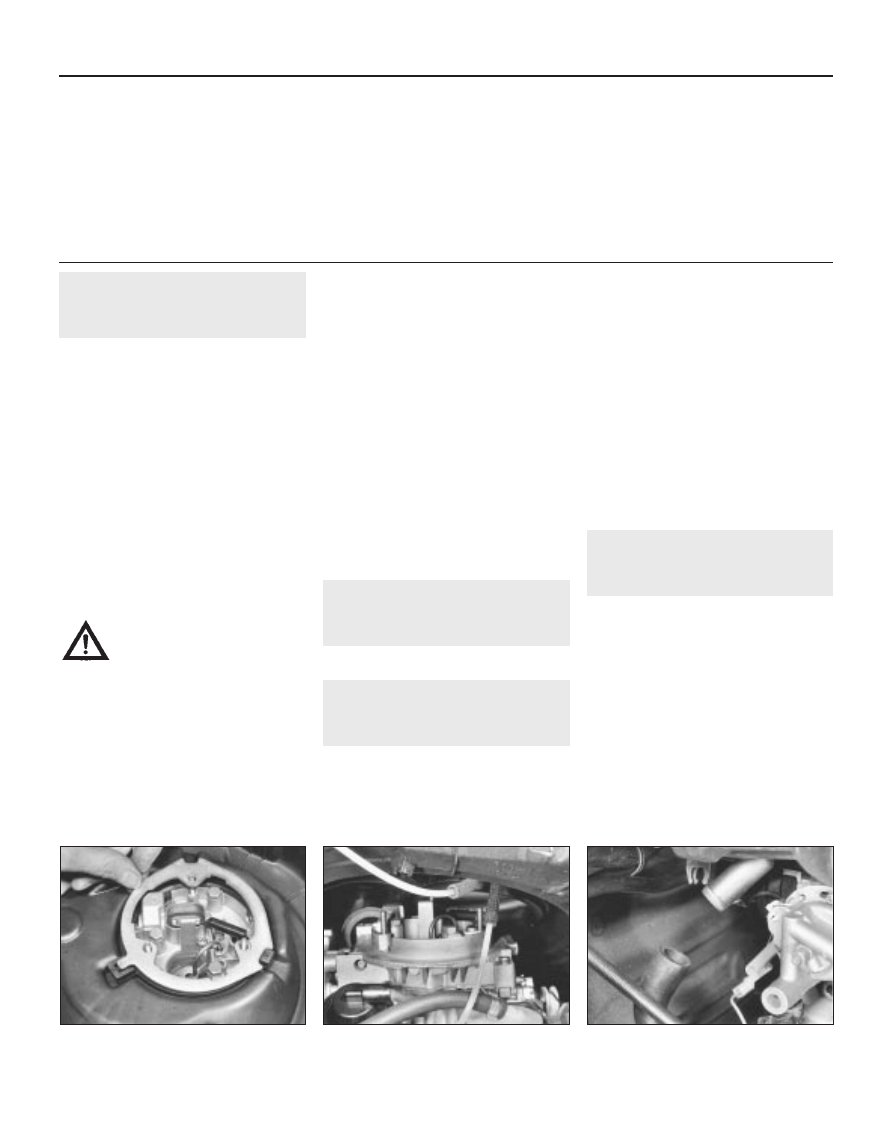
1 Remove the element.
2 Unscrew the nut(s) securing the air cleaner
body and remove the adapter or retaining ring
(see illustration).
3 Note the location of all hoses and tubes
then disconnect them. Withdraw the air
cleaner body from the carburettor and remove
the sealing ring (see illustrations).
4 Refit in the reverse order of removal,
ensuring that all hose connections are
securely made.
1.6 and 1.8 litre engines
5 Remove the element.
6 Unclip and detach the air hose at the side
of the cleaner body (see illustration).
7 Undo the retaining nut at the top and lift the
cleaner unit clear, disconnecting the
remaining hoses.
8 Refit in the reverse order of removal. Fit a
new sealing washer if the old one has
perished or distorted.
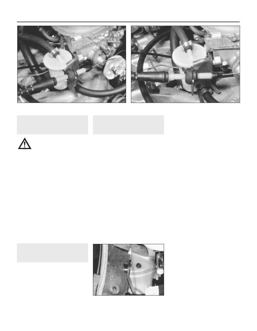
4
Automatic air cleaner
temperature control - testing
2
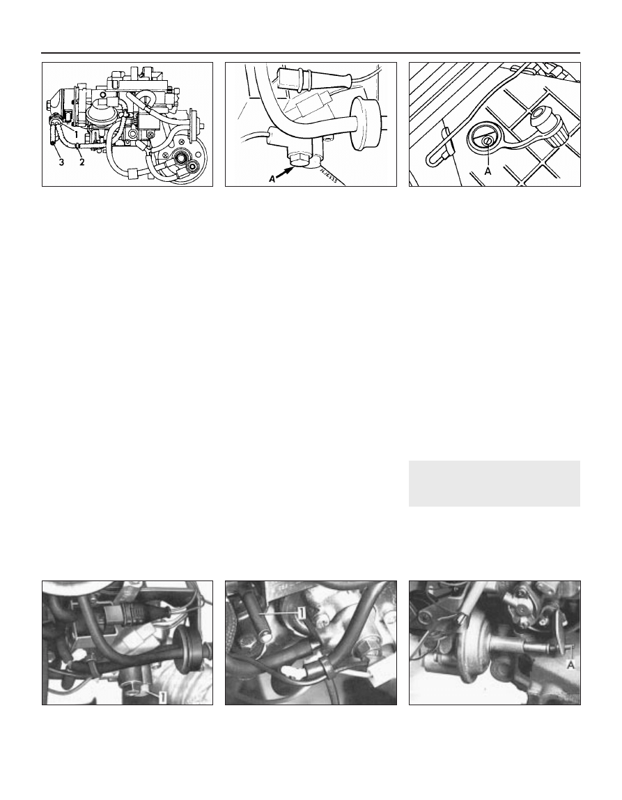
1 Unclip and remove the vacuum unit and
inlet pipe but leave the vacuum pipe
connected
(see illustration).
2 Suspend a thermometer in the flow of air
through the inlet duct then start the engine.
Between -20°C and + 20°C, the control flap in
the unit should be a maximum of 2/3rds open
to admit hot air from the exhaust manifold.
Above 20°C, the control flap must close the
hot air supply (see illustration).
3 The control flap movement can be checked
by sucking on the vacuum inlet.
4 With the engine running and inlet air
temperature above 20°C, disconnect the
vacuum hose from the vacuum unit. The
control flap should fully open within a
maximum of 20 seconds.
4A•4 Fuel and exhaust systems - carburettor models
3.2 Removing air cleaner body retaining
ring - 1.3 litre
3.3a Disconnecting temperature sensor
hose . . .
3.3b . . . and crankcase emission hose -
1.3 litre
1081 VW Golf & Jetta
Fuel and exhaust systems - carburettor models 4A•5
4A
1081 VW Golf & Jetta
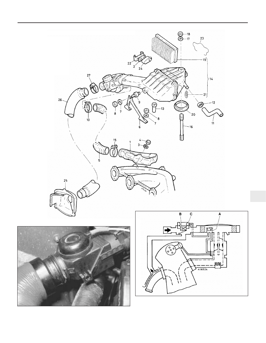
3.6 Air cleaner components – 1.6 and 1.8 litre
1 Warm air deflector plate
2 Gasket
3 Spring washer
4 Nut
5 Air hose
6 Bracket
7 Washer
8 Nut
9 Bonded rubber mounting
10 Clip
11 Air Hose
12 Clip
13 Spacer tube
14 Air cleaner
15 Clip
16 Stud
17 Washer
18 Self-locking nut
19 Filter element
20 Sealing washer
21 Spring
22 Lockplate
23 Retaining clip
24 Dual thermostat
25 Union
26 Air hose
27 Clip
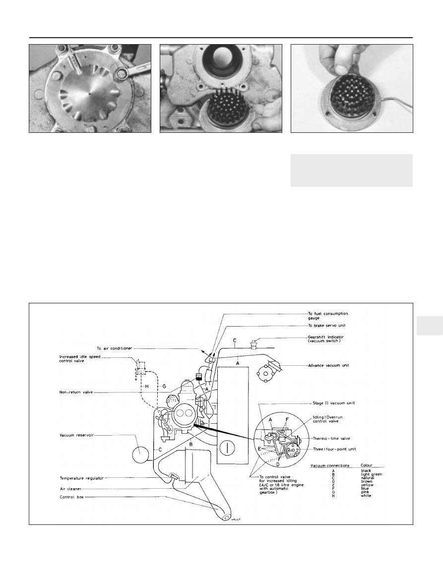
4.2 Air cleaner load and temperature control diagram –
1.05 and 1.3 litre
A Temperature regulator
B Intake pipe with thermostat
C Vacuum unit
4.1 Air cleaner vacuum unit
5 If the control unit does not operate correctly
then renew it, together with the temperature
sensor (see illustration).
6 Refit the vacuum unit and inlet pipe.
5
Fuel pump - testing, removal
and refitting
3
Testing
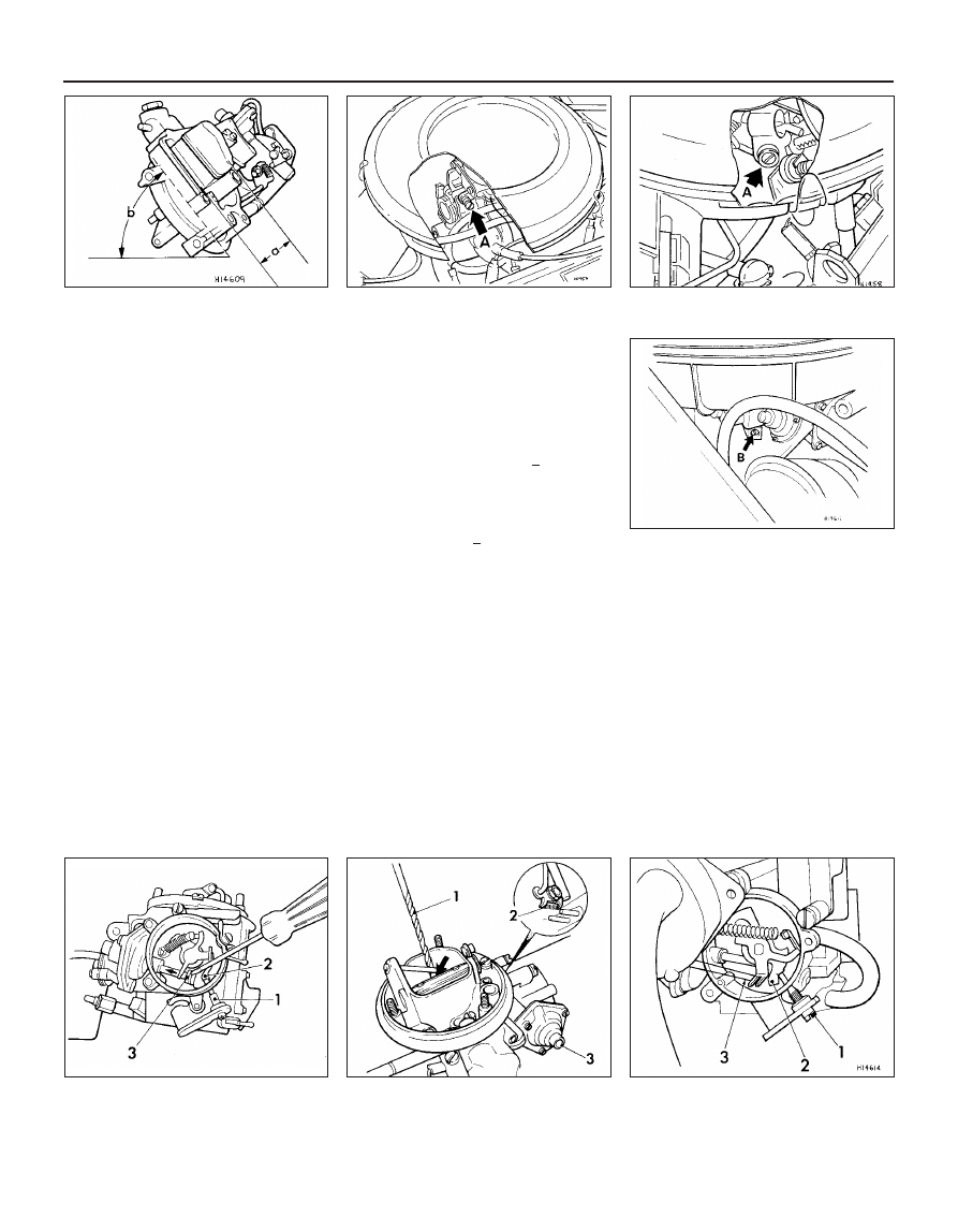
1 Pump location is dependent on engine type
and is as follows:
a) 1.05 and 1.3 litre engines - The pump is
located on the right-hand side of the
engine, forward of the carburettor (see
illustration). Mounted on the cylinder
head, it is driven indirectly from the
camshaft.
b) 1.6 and 1.8 litre engines - The pump is
located on the side of the cylinder block,
next to the oil filter mounting bracket. It is
driven direct from the intermediate shaft.
2 If the pump is suspected of malfunctioning,
disconnect the supply pipe from the
carburettor (air cleaner removed) and the LT
lead from the coil positive terminal. Ensure
that there is fuel in the tank. Turn the engine
on the starter while holding a wad of rag near
the fuel pipe. If the pump is operating
correctly, well defined spurts of fuel should be
ejected from the pipe.
3 If the pump is malfunctioning then it must
be renewed, as it is not possible to service or
repair it. However, prior to removal of the
pump, check the in-line filter for blockage.
Removal
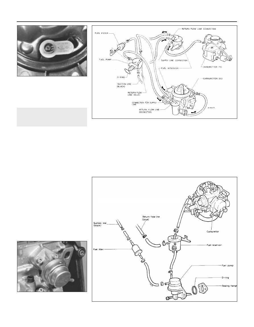
4 To remove the fuel pump, first identify the
hoses for position then disconnect them from
the pump (see illustrations).
5 Using a suitable splined or Allen key,
unscrew the pump retaining bolts and
withdraw the unit from the cylinder head or
cylinder block (as applicable). Remove the
sealing ring and, if applicable, note the earth
lead location.
6 Clean the mating faces of the pump and
cylinder head or cylinder block/seal flange.
Refitting
7 Refitting is a reversal of the removal
procedure. Renew the seal ring and, where
crimped type hose clips were used, change
them to screw type clips.
8 On completion, check all hose connections
with the engine running and look for any sign
of fuel leakage.
4A•6 Fuel and exhaust systems - carburettor models
4.5 Upper view of air temperature sensor -
1.3 litre
5.1 Fuel pump location - 1.3 litre
1081 VW Golf & Jetta
5.4a Fuel line attachments – 1.05 and 1.3 litre
5.4b Fuel pump and line connections –
1.6 and 1.8 litre
6
Fuel reservoir - removal and
refitting
2
1 The fuel reservoir is located between the
fuel pump and the carburettor (see
illustration). The reservoir has three hose
connections which are marked as follows:
a) From the pump - arrow marked
b) To the carburettor - not marked
c) To the fuel return line - marked R
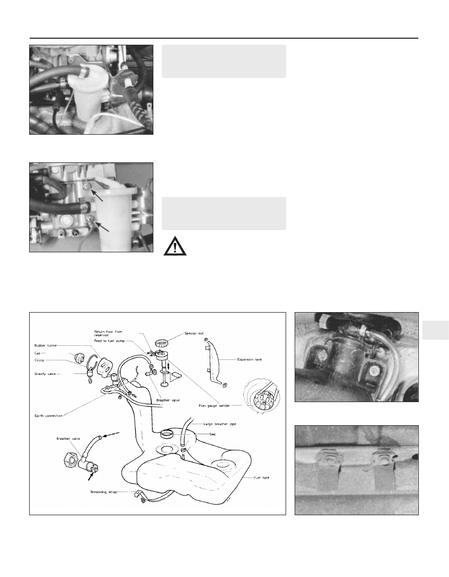
2 To remove the reservoir, disconnect the
three hoses and plug them to prevent leakage.
3 Remove the support bracket retaining
screws and lift away the reservoir. Note the
earth lead connection (see illustration).
4 Refit in the reverse order to removal and
then check for any signs of leakage on
completion.
7
Fuel tank - removal and
refitting
3
Warning: The fuel tank must
always be removed in a well
ventilated area and never over a
pit
Removal
1 Disconnect the battery negative lead.
2 Siphon or pump all the fuel from the tank
(there is no drain plug) .
3 Lift the floor covering from the luggage
compartment then remove the circular sender
unit cover (see illustration).
4 Disconnect the wiring plug from the top of
the sender unit, also the fuel feed (to pump)
and return (from fuel reservoir) hoses.
5 Jack up the rear of the vehicle and support
it on axle stands (see “Jacking and vehicle
support”). Chock the front wheels, remove the
right-hand side rear wheel.
6 Disconnect the breather hose from the filler
neck (see illustration).
7 Disconnect the expansion tank-to-filler
neck hose and breather pipe.
8 Disconnect the filler neck funnel which is
secured by a large C-clip.
9 Support the fuel tank with a trolley jack and
length of wood. Unscrew the retaining nuts
and bolts, detach the straps (see illustration)
and lower the tank to the ground. On GTi
models, it will also be necessary to detach the
side protector plate.
10 If the expansion reservoir is to be
removed, undo the retaining bolt and lower it
from the wheel arch.
11 If the tank is contaminated with sediment
or water, remove the gauge sender unit and
swill the tank out with clean fuel. If the tank is
damaged or leaks, it should be repaired
professionally or renewed.
Refitting
12 Refitting is a reversal of removal. Make
sure that the rubber packing strips are fitted
to the retaining straps. Refit the hoses free of
any kinks.
Fuel and exhaust systems - carburettor models 4A•7
4A
6.1 Fuel reservoir location - 1.3 litre
6.3 Fuel reservoir retaining screws
(arrowed)
Note earth lead connection to lower screw
7.6 Fuel filler breather valve and hose
7.9 Fuel tank retaining strap-to-floor bolts
1081 VW Golf & Jetta
7.3 Fuel tank and associated components
8
Fuel gauge sender unit -
removal and refitting
2
Warning: The fuel gauge sender
unit must always be removed in
a well ventilated area.
Removal
1 Disconnect the battery negative lead.
2 Lift the luggage compartment floor covering
and remove the circular sender unit cover.
3 Disconnect the wiring connector from the
top of the unit then detach the fuel supply and
return hoses.
4 Undo the retaining nut and lift out the unit,
noting its orientation alignment marking. A
suitable wrench may be necessary to loosen
the securing nut.
5 Renew the sender unit seal.
Refitting
6 Refit in the reverse order to removal, noting
the following:
a) Check that the unit is correctly aligned
with the markings in register
b) Replace the crimped supply and return
line clips with screw type clips
c) Check that the wiring connection is secure.
9
Fuel filler gravity valve -
removal, testing and refitting
1
1 The gravity valve is located in the fuel filler
neck and is accessible from within the
right-hand rear wheel arch.
2 To remove the valve, pull it upwards from
the fuel filler neck and unclip it.
3 When the valve is held vertically, it must be
open. When the valve is angled at 45° then it
must shut. Renew the valve if found to be
defective.
4 Refit in the reverse order of removal.
10 Accelerator and throttle
cables - removal, refitting and
adjustment
2
Manual gearbox
Removal
1 Disconnect the battery earth lead.
2 Remove the air cleaner unit.
3 Prise free and release the inner cable
securing clip(s) at the carburettor throttle
control, noting their location (see illustration).
4 Release the cable grommet from the
support bracket (see illustration).
5 Working inside the vehicle, remove the
lower facia panel then unclip the inner cable
from the accelerator pedal (see illustration).
6 Withdraw the complete accelerator cable
into the engine compartment, together with
the rubber grommets.
Refitting
7 Refitting of the accelerator cable is a
reversal of removal. Make sure that the cable
is free of kinks. Adjust it as follows before
refitting the air cleaner.
Adjustment
8 Before adjusting the cable, check that it is
correctly aligned over its full length.
9 Have an assistant fully depress the
accelerator pedal.
10 Check that the clearance between the
throttle lever at the carburettor and the fully open
stop is a maximum of 1.0 mm. Note that the
throttle lever must not be hard against the fully
open stop (ie. there must be a small clearance).
11 There are different cable adjustment
arrangements which are as follows:
a) Where locknuts are provided at the
engine end of the outer cable, loosen
them then adjust the cable position and
tighten the locknuts
b) Where a ferrule and circlip are provided,
extract the circlip, adjust the cable
position then refit the circlip so that it is
abutting the ferrule guide
c) On some models, it is necessary to adjust
the inner cable by loosening the clamp
screw, repositioning the lever while
holding the cable taut then tightening the
screw
12 After adjustment refit the air cleaner.
Automatic transmission
Removal
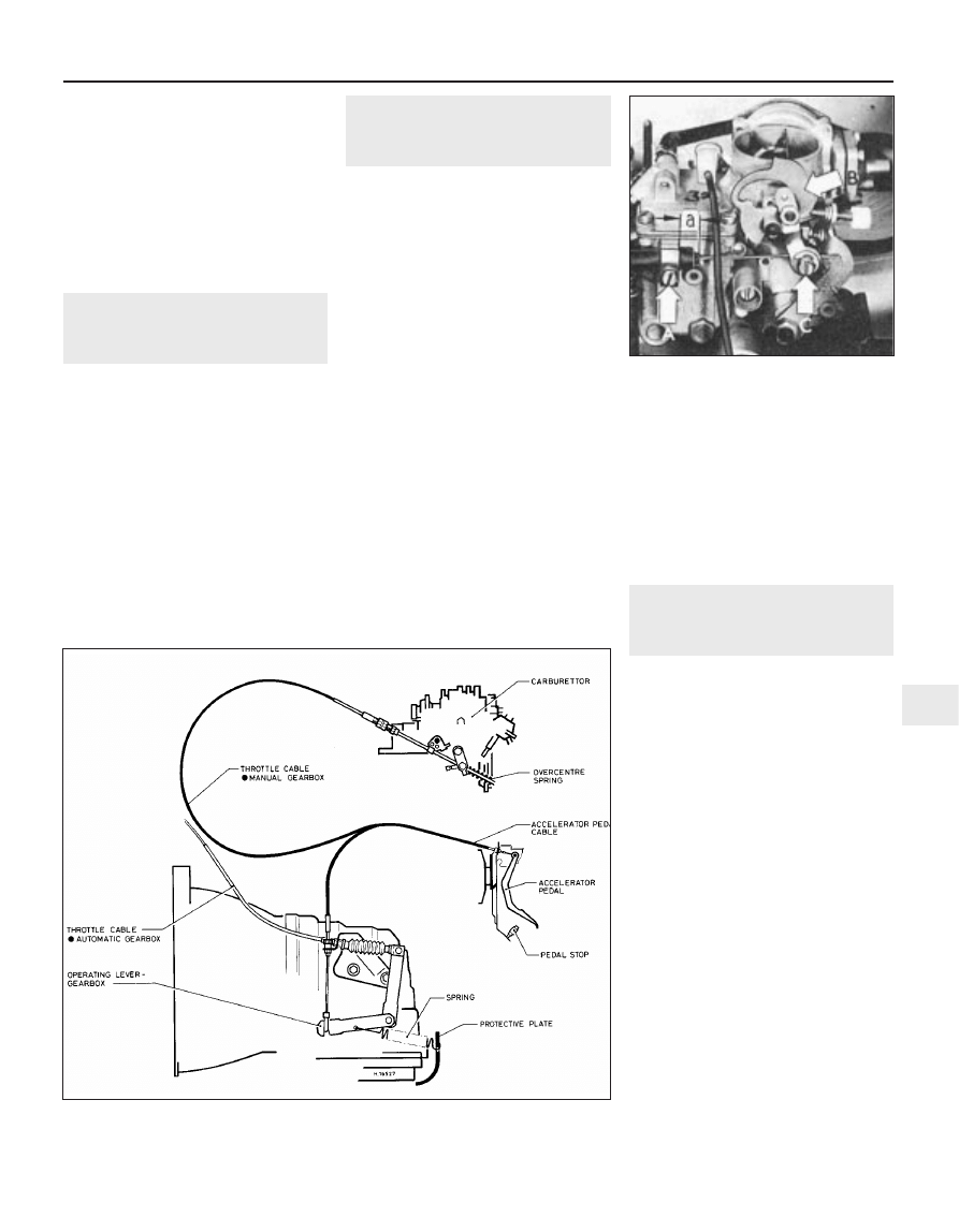
13 On automatic transmission models, the
accelerator pedal activates the accelerator
cable which is attached to the operating lever
of the gearbox shift control. This simul-
taneously operates the throttle cable fitted
between the shift mechanism and the
carburettor
(see illustration).
14 Before removing either cable, select P
(Park).
15 To remove the accelerator pedal cable,
first loosen the cable adjusting nut then
detach the inner cable from the operating
lever clevis and the outer cable from its
location bracket. The cable can then be
disconnected from the pedal and removed in
the same manner as that for manual gearbox
models.
16 To remove the throttle cable, loosen the
adjuster and locknut at the carburettor
support bracket, remove the inner cable
4A•8 Fuel and exhaust systems - carburettor models
10.3 Accelerator cable to carburettor throttle control
10.4 Release cable grommet from support bracket
10.5 Accelerator cable-to-pedal
attachment
1081 VW Golf & Jetta
retaining clip and then disconnect the cable
from the carburettor.
17 At the transmission end, prise free the
securing clip and detach the cable from the
operating lever and the cable support bracket.
Refitting
18 Refitting of both cables is a reversal of the
removal procedure.
Adjustment
19 This procedure is described in Chapter
7B.
11 Accelerator pedal - removal
and refitting
2
Removal
1 Remove the lower facia panel.
2 Disconnect the accelerator cable from the
pedal
3 Prise out the clip and remove the pivot pin.
4 Remove the accelerator pedal. If necessary
press out the pivot pin bushes.
Refitting
5 Refitting is a reversal of removal. Lubricate
the bushes with a little grease and check
cable adjustment.
12 Choke cable (1.05 litre
engine) - removal, refitting
and adjustment
2
Removal
1 Disconnect the battery negative lead.
2 Remove the air cleaner.
3 Using a screwdriver, loosen the inner and
outer cable clamps and disconnect the cable
from the carburettor.
4 Working inside the vehicle, remove the
lower facia panel.
5 Pull out the clip and remove the choke
knob.
6 Unscrew the ring and withdraw the cable
from the facia.
7 Disconnect the wiring and withdraw the
complete cable from inside the vehicle.
Refitting
8 Refitting is a reversal of removal. Make sure
that the cable is correctly aligned and that the
grommets are firmly fitted in the bulkhead.
Adjust it as follows before refitting the air
cleaner.
Adjustment
9 Locate the outer cable in the clamp so that
its end protrudes by approximately 12.0 mm.
Tighten the clamp with the outer cable in this
position (see illustration).
10 Push the choke knob fully in then pull it
out by 3.0 mm. Switch on the ignition and
check that the warning lamp is not lit.
11 Insert the inner cable into the choke lever
clamp and fully open the choke lever by hand.
Tighten the inner cable clamp screw in this
position.
12 Refit the air cleaner.
13 Carburettor - removal and
refitting
3
Removal
1 Disconnect the battery earth lead.
2 Remove the air cleaner unit.
3 Disconnect the accelerator cable from the
carburettor.
4 Disconnect the wiring from the following, as
applicable:
a) Fuel cut-off solenoid
b) Bypass air cut-off valve
c) Part throttle channel heater
d) Automatic choke control unit
e) Earth point
5 Drain off half the engine coolant then
disconnect the coolant hoses from the
automatic choke unit and the expansion
element (where applicable) (see illustrations).
6 Disconnect the fuel supply and return
hoses at the carburettor/fuel reservoir, as
necessary, and plug or clamp the hoses to
prevent fuel leakage. Note the connections in
case of confusion when refitting.
7 Disconnect the vacuum hoses and note
their connections.
8 Unscrew the through-bolts or retaining
nuts, as applicable, and carefully remove the
carburettor from the inlet manifold (see
illustration).
9 To remove the intermediate flange from the
manifold, undo the four nuts on the manifold
underside and lift the flange clear.
Fuel and exhaust systems - carburettor models 4A•9
4A
1081 VW Golf & Jetta
10.13 Accelerator/throttle cable connections – manual gearbox and automatic
transmission variants with 2E2 carburettor
12.9 Choke cable adjustment setting –
1.05 litre
A Outer cable projection
B Cam and stop
C Choke inner cable connection
Refitting
10 Refitting is a reversal of the removal
procedure. Ensure that the inlet manifold,
intermediate flange and carburettor mating
faces are clean and use new gaskets.
11 On completion, top-up the cooling
system, restart the engine and check for fuel
and coolant leaks.
12 Adjust the carburettor as necessary.
14 Carburettor - overhaul
4
1 A complete strip-down of a carburettor is
unlikely to cure a fault which is not
immediately obvious without introducing new
problems. If persistent carburation problems
are encountered, it is recommended that the
advice of a VW dealer or carburettor specialist
is sought. Most dealers will be able to provide
carburettor re-jetting and servicing facilities
and if necessary, it should be possible to
purchase a reconditioned carburettor of the
relevant type.
2 If it is decided to go ahead and service a
carburettor, check the cost and availability of
spare parts before commencement. Obtain a
carburettor repair kit, which will contain the
necessary gaskets, diaphragms and other
renewable items.
3 When working on carburettors, scrupulous
cleanliness must be observed and care must
be taken not to introduce any foreign matter
into components. Carburettors are delicate
instruments and care should be taken not to
disturb any components unnecessarily.
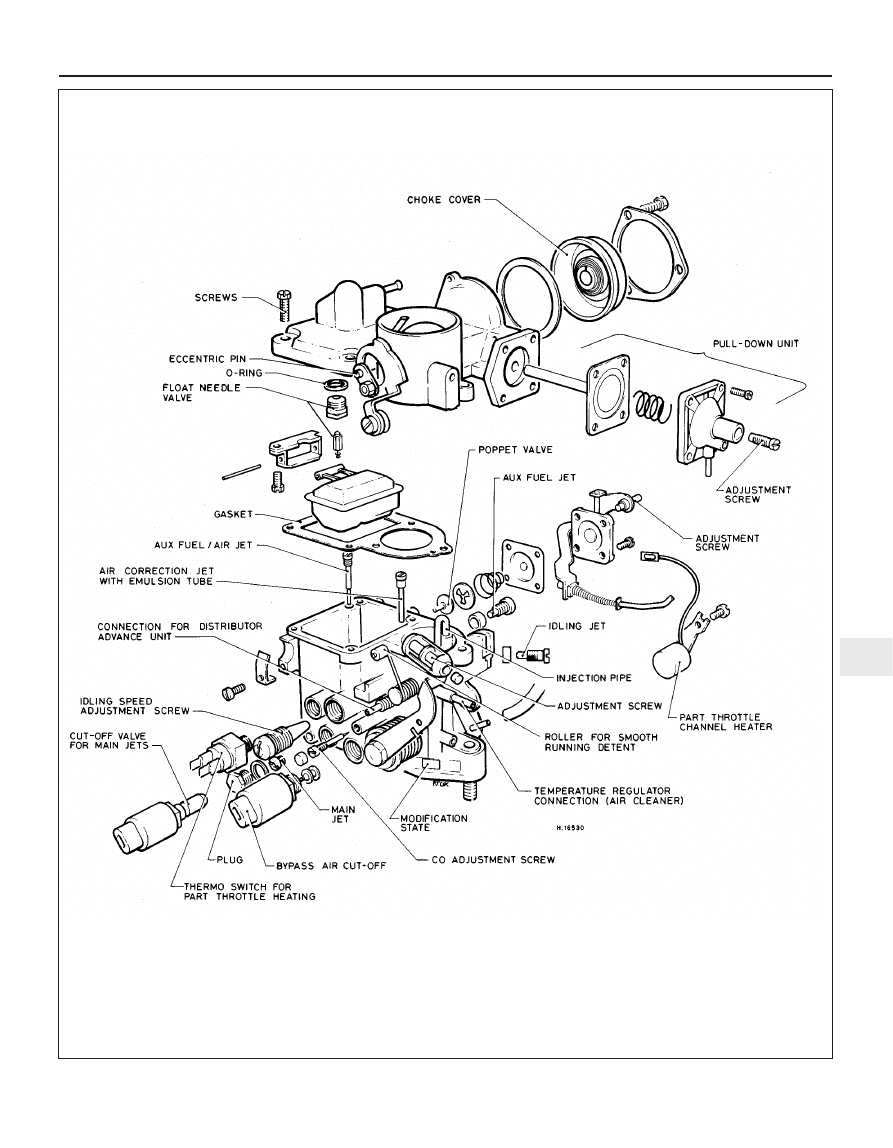
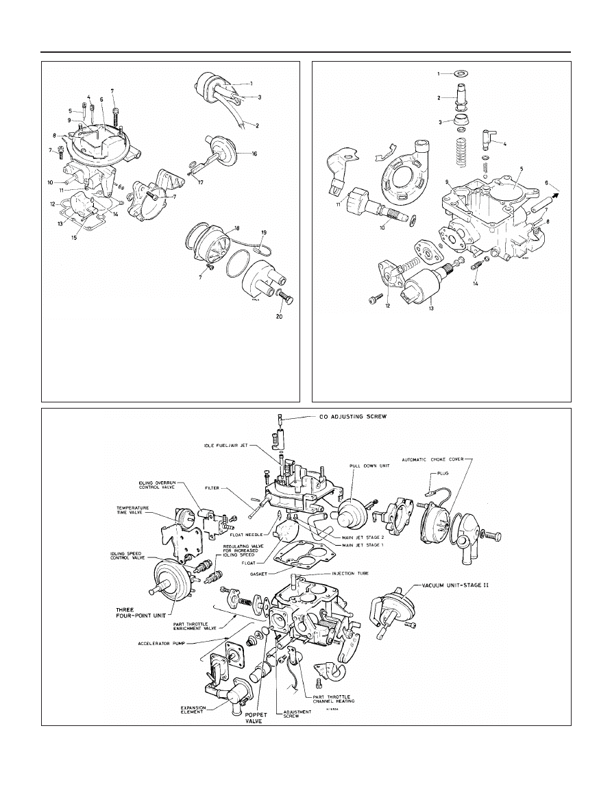
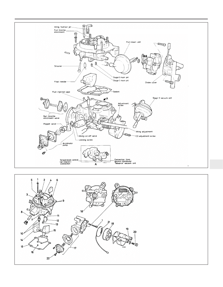
4 Referring to the relevant exploded view of
the carburettor (see illustrations), remove
each component part whilst making a note of
its fitted position. Make alignment marks on
linkages, etc.
5 Reassemble the carburettor in the reverse
order to dismantling, using new gaskets, O-
rings etc. Be careful not to kink any
diaphragms.
4A•10 Fuel and exhaust systems - carburettor models
13.8 Carburettor securing bolts (arrowed)
– Pierburg/Solex 2E3
1081 VW Golf & Jetta
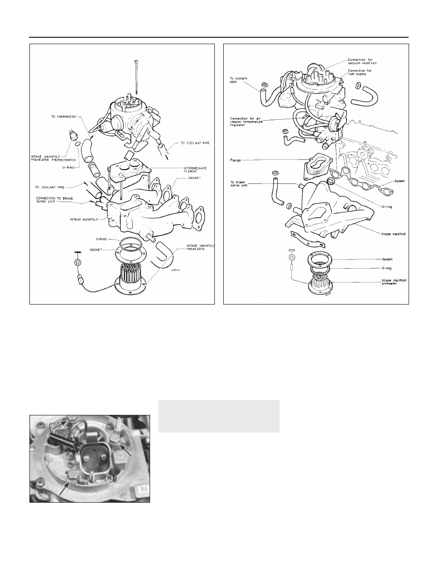
13.5a Pierburg/Solex 2E3 carburettor, manifold and associated
components
13.5b Pierburg/Solex 2E2 carburettor, manifold and associated
components
Fuel and exhaust systems - carburettor models 4A•11
4A
1081 VW Golf & Jetta
14.4a Pierburg/Solex PIC carburettor components
4A•12 Fuel and exhaust systems - carburettor models
1081 VW Golf & Jetta
14.4d Pierburg/Solex 2E2 carburettor
components
14.4b Pierburg/Solex 1B3 carburettor top cover
components
1 Idle speed boost
two-way valve
2 To idle adjustment
screws
3 To vacuum line
and brake servo
4 Idling fuel/air jet
5 Auxiliary fuel/air jet
6 Choke valve
7 Screw
8 Cover
9 Enrichment tube
10 Fuel supply
11 Main jet
12 Gasket
13 Float
14 Needle valve
15 Pivot pin
16 Pull-down unit
17 Adjustment screw
18 Automatic choke
19 Wiring connector
20 Screw
14.4c Pierburg/Solex 1B3 carburettor main body components
1 Bearing ring
2 Pump plunger
3 Seal
4 Injection tube
5 Main body
6 To pull-down unit
7 To air cleaner vacuum control
8 Fast idle adjustment screw
9 Part throttle enrichment jet
10 Idle speed adjustment screw
11 To two-way valve
12 Part throttle enrichment valve
13 Idle cut-off solenoid
14 Mixture adjustment screw
Fuel and exhaust systems - carburettor models 4A•13
4A
1081 VW Golf & Jetta
14.4e Pierburg/Solex 2E3 carburettor components
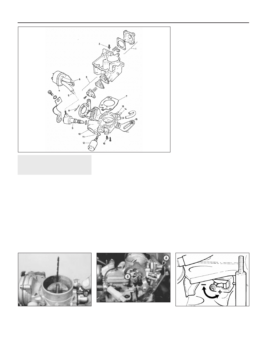
14.4f Weber 32 TLA carburettor top cover components
1 Screw
2 Air correction jet
3 Auxiliary fuel jet (if applicable)
4 Idling fuel jet
5 Emulsion tube
6 Choke valve and lever
7 Washer
8 Gauze filter
9 Plugs
10 Needle valve
11 Pin
12 Atomiser
13 Gasket
14 Float
15 Pin
16 Main jet
17 Pull-down unit
18 Automatic choke
19 Sealing ring
20 Screw
21 Heater plate
22 Adjusting screw
15 Carburettor (1.05 litre
engine) - adjustments
4
Note: Accurate adjustment of the carburettor
is only possible if adjustment of the ignition
timing, dwell angle and spark plug gaps is
correct. Incorrect valve clearances can also
effect carburettor adjustment
Pierburg/Solex 31 PIC7
Bypass air cut-off valve
1 To check the bypass air cut-off valve when
removed, depress the pin approximately 3 to 4
mm then energise it with battery voltage. A
click should be heard and the pin should move
out.
Cut-off valve
2 To check the cut-off valve for the main jets
(where fitted), apply battery voltage. It must
be heard to click when the voltage is applied.
Choke valve gap
3 To adjust the choke valve gap, operate the
choke lever fully then return it to the smooth
running detent and hold it there. With the
choke spindle lever against the cam, check
that the clearance between the choke valve
and barrel is as shown in Specifications. Use a
twist drill to make the check and if necessary,
adjust the clearance by turning the adjusting
screw as required (see illustrations).
4 Although the choke valve gap smooth
running detent position is preset during
manufacture its setting can be checked and if
necessary adjusted. Pull the choke out fully,
then push it onto the smooth running detent.
Press the choke lever against the cam and
check the choke valve gap with a twist drill, as
in the previous paragraph. If the gap is not as
specified, adjust by turning the eccentric pin
on the choke spindle lever.
Accelerator pump injection capacity
5 The accelerator pump injection capacity
may be checked with the carburettor fitted or
removed. However, the air cleaner must be
removed and the float chamber must be full.
6 Open the choke valve and retain it in the
open position with a piece of wire, then push
a length of close fitting plastic tube over the
injection pipe. Operate the throttle until fuel
emerges then place the tube in a measuring
glass. Operate the throttle fully five times
allowing at least three seconds per stroke.
Divide the final quantity by five to determine
the amount per stroke and compare with the
amount specified. If necessary, reposition the
adjusting screw on the accelerator pump lever
(see illustration). Note that fuel must be
injected into the throttle valve gap. If
necessary, bend the injection pipe.
Slow running and fast idle
7 Run the engine to normal operating
temperature then stop it. Connect a
tachometer and, if available, an exhaust gas
analyser.
8 Check that all electrical accessories are
switched off and note that slow running
adjustments should not be made while the
radiator cooling fan is running.
9 Disconnect the crankcase ventilation hose
from the air cleaner body and plug the air
cleaner outlet.
4A•14 Fuel and exhaust systems - carburettor models
15.3a Checking choke valve gap with twist
drill
15.3b Adjusting screw location for choke
valve gap (A) and choke valve gap smooth
running detent eccentric pin (B)
15.6 Accelerator pump adjuster screw
1081 VW Golf & Jetta
14.4g Weber 32 TLA carburettor main
body components
1 Accelerator pump
2 Injection pipe
3 Part throttle enrichment valve
4 Idle speed boost two-way valve
5 To idle adjusting screw
6 To vacuum line and brake servo
7 Gasket
8 Clip
9 Idle speed adjustment screw
10 Throttle housing
11 Sealing ring
12 Idle cut-off solenoid
13 To air cleaner
14 To distributor
15 Fast idle adjustment screw
16 Mixture adjustment screw
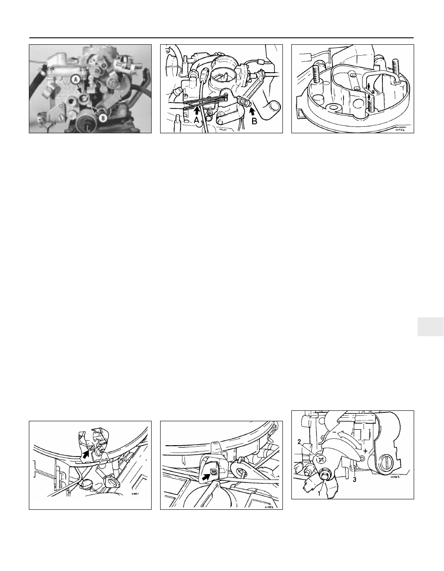
10 Start the engine and let it idle. Check that
the engine speed and CO content are as
specified. If not, turn the two screws located
above the cut-off solenoid alternately as
necessary (see illustration).
11 If an exhaust gas analyser is not
immediately available, an approximate
mixture setting can be made by turning the
mixture screw to give the highest engine
speed.
12 Reconnect the crankcase ventilation
hose. If this results in an increase in the CO
content, the engine oil is diluted with fuel and
should be renewed. Alternatively, if an oil
change is not due, a long fast drive will reduce
the amount of fuel in the oil.
13 Stop the engine and remove the
tachometer and exhaust gas analyser.
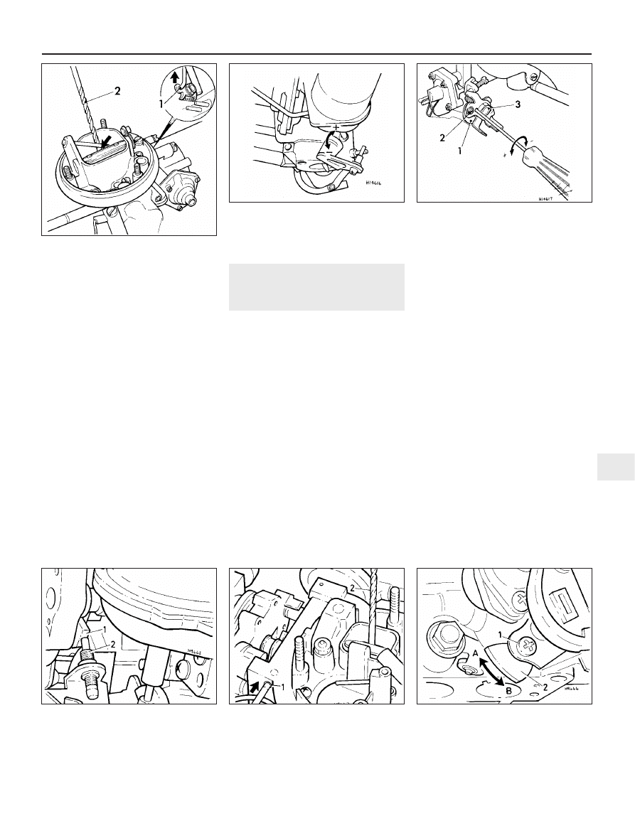
14 To adjust the fast idle speed, first check
that the engine is still at normal operating
temperature. Remove the air cleaner.
15 With the engine stopped, pull the choke
control knob fully out then push it in to the
smooth running detent.
16 Retain the choke valve in its open position
using an elastic band.
17 Connect a tachometer then start the
engine and check that the fast idle speed is as
specified. If not, turn the adjustment screw on
the side of the choke lever cam. Note that this
screw may also have a tamperproof cap (see
illustration).
18 Stop the engine, disconnect the
tachometer and elastic band, then refit the air
cleaner. Push the choke control knob fully in.
Pierburg/Solex 1B3
19 All adjustments are as described for the
Pierburg 2E3 carburettor fitted to the 1.3 litre
engine, with the following additions.
Enrichment tube
20 With the choke valve closed, the bottom
of the enrichment tube should be 1.0 mm
from the valve (see illustration).
Idle speed and mixture
21 Before making any adjustment, ensure
that the automatic choke is fully open,
otherwise the throttle valve linkage may still
be on the fast idle cam.
Idle speed boost valve
22 The idle speed adjustment screw (see
illustration) incorporates a vacuum-operated
valve which opens if the idle speed drops
below 700 rpm, thereby causing an increase
in the idle speed. The valve is itself controlled
by a two-way valve and further control unit.
The control unit monitors the engine speed
and activates the two-way valve which applies
vacuum to the idle valve.
23 To test the system, run the engine at idle
speed, then slowly reduce the engine speed
by manually closing the choke valve. At 700
rpm there should be vacuum at the hose in
the idle valve.
Fast idle speed
24 With the engine at normal operating
temperature and switched off, connect a
tachometer and remove the air cleaner.
25 Fully open the throttle valve, then turn the
fast idle cam and release the throttle valve so
that the adjustment screw is positioned on the
second highest part of the cam.
26 Without touching the accelerator pedal,
start the engine and check that the fast idle
speed is as specified. If not, turn the
adjustment screw on the linkage as necessary.
If a tamperproof cap is fitted, renew it after
making the adjustment (see illustration).
Choke valve gap
27 With the engine cold, fully open the throttle
valve, then turn the fast idle cam and release
the throttle valve so that the adjustment screw
is positioned on the highest part of the cam.
28 Press the choke operating rod as far as
possible towards the pull-down unit.
29 Using the shank of a twist drill, check that
the distance from the choke valve to the
carburettor wall is as specified. If not, adjust
the screw behind the automatic choke.
Accelerator pump capacity
30 Hold the carburettor over a funnel and
measuring glass.
31 Turn the fast idle cam so that the
adjusting screw is off the cam. Hold the cam
in this position during the following procedure.
32 Fully open the throttle ten times, allowing
at least three seconds per stroke. Divide the
total quantity by ten and check that the
resultant injection capacity is as specified. If
not, loosen the camplate locking screw, turn
the camplate as required and tighten the
screw (see illustration).
Fuel and exhaust systems - carburettor models 4A•15
4A
15.10 Idle speed (A) and mixture (B)
adjusting screw locations
15.17 Fast idle speed setting
A Choke valve held open with rubber band
B Adjustment screw
15.20 Enrichment tube adjustment
a = 1.0 ± 0.3 mm
15.22 Idle speed adjustment screw
location
15.26 Mixture (CO content) adjustment
screw location
15.32 Accelerator pump adjustment
1 Nut 2 Camplate locking screw
3 Camplate
1081 VW Golf & Jetta
33 If difficulty is experienced in making the
adjustment, check the pump seal and make
sure that the return check valve and injection
tube are clear.
Idle cut-off solenoid
34 When the ignition is switched on, the
solenoid should be heard to click, indicating
that the idle circuit has been opened.
35 If the solenoid is removed for testing, the
plunger must first be depressed by 3.0 to 4.0
mm before switching on the unit.
Weber 32 TLA
Float level
36 With the upper part of the carburettor
inverted and held at an angle of approximately
45°, the measurement “a” (see illustration)
should be as shown. The ball of the float
needle should not be pressed in against the
spring when making the measurement,
Idle speed and mixture
37 The procedure for checking and adjusting
the idle speed and CO content are basically
the same as given for the Pierburg 31 PIC-7
carburettor. Refer to the accompanying
illustrations for the location of adjustment
screws and to the Specifications for settings.
(see illustrations).
Idle speed boost valve
38 The idle speed boost valve is identical to
the unit on the Pierburg 1B3 carburettor.
Choke valve gap (pull-down)
39 Remove the choke cover.
40 Place the fast idle speed adjusting screw
on the highest step of the cam (see
illustration). The manufacturer’s original
instruction was to press the pull rod in the
direction of the arrow shown, then to check
that the choke valve gap is 2.5 + 0.2 mm. As
from April 1987 however, this instruction is
revised and it is now necessary to use a
vacuum pump to apply 300 mbar vacuum on
the pull-down unit. The choke valve gap in
this case must be 2.0 + 0.2 mm.
41 Adjustment is made on the screw at the
end of the pull-down device. Ensure that the
spring “2” (see illustration)
is not
compressed when making the check.
Idle cut-off valve
42 To check the cut-off valve, apply battery
voltage. The valve must be heard to click
when voltage is applied.
Fast idle speed
43 Before carrying out this check, ensure
that the ignition timing and manual idling
adjustments are correct. The engine should
be at normal operating temperature.
44 Remove the air cleaner.
45 Plug the temperature regulator
connection.
46 Connect the tachometer.
47 Remove the choke cover and set the fast
idle speed adjusting screw on the second
highest step on the cam (see illustration).
48 Tension the operating lever with a rubber
band so that the choke valve is fully open.
49 Without touching the accelerator pedal,
start the engine, which should run at the fast
idle speed specified.
50 Adjust the screw as necessary.
Choke valve gap (wide open kick)
51 Remove the air cleaner.
52 Fully open the throttle and hold it in this
position.
53 Press the lever (1) upwards (see
illustration).
54 Check the gap with a twist drill. The gap
should be as specified. If necessary, adjust by
bending the lever (see illustration).
4A•16 Fuel and exhaust systems - carburettor models
15.36 Float level checking diagram
a = 28 ± 1.0 mm b = 45° angle
15.37a Idle speed adjusting screw (A) -
pre June 1985
15.37b Idle speed adjusting screw (A) -
from July 1985
15.40 Choke valve gap adjustment
15.37c Mixture (CO content) adjusting
screw (B)
15.41 Checking choke valve gap (pull-down)
15.47 Adjusting fast idle speed
1 Fast idle adjusting screw
2 Cam 3 Rubber band
1 Twist drill
2 Spring
3 Adjusting screw
1 Fast idle adjustment screw
2 Cam 3 Pull rod
1081 VW Golf & Jetta
Accelerator pump capacity
55 This can be checked by following the
procedure given for the Pierburg 2E3
carburettor, with the following differences.
56 Open the throttle valve quickly when
operating the pump (ie. one second per
stroke, with pauses of three seconds between
strokes).
57 The amount of fuel injected can be
altered, but only very slightly, as follows: (see
illustration).
58 Take the accelerator cable cam off the
throttle valve lever.
59 Secure the accelerator pump cam with an
M4 screw.
60 Loosen the locknut on the camplate
securing screw. Loosen the screw and turn
the camplate with a screwdriver clockwise to
decrease injected fuel and anti-clockwise to
increase injected fuel. Tighten the screw and
locknut and recheck the injection capacity.
16 Carburettor (1.3 litre engine)
- adjustments
4
Note: Accurate adjustment of the carburettor
is only possible if adjustment of the ignition
timing, dwell angle and spark plug gaps is
correct. Incorrect valve clearances can also
effect carburettor adjustment
Pierburg/Solex 2E3
Cut-off valve
1 To check the cut-off valve, apply battery
voltage. It must be heard to click when the
voltage is applied.
Choke valve gap
2 To check the choke valve gap the choke
cover must be removed. Move the throttle
valve and the fast idle cam so that the
adjustment screw is against the highest cam
stop. Now push the choke valve operating rod
fully towards the adjustment screw (and
pull-down unit), then check the choke
valve-to-barrel clearance using a twist drill as
a gauge. If necessary turn the adjuster screw
as required to provide the specified choke
valve gap (see illustrations).
Accelerator pump injection capacity
3 The accelerator pump injection capacity
can be checked in the same manner as that
described for the Pierburg 2E3 carburettor but
allow 1 second per stroke and 3 seconds
between strokes (see illustration).
Choke
4 The automatic choke cover and choke
housing alignment marks should correspond.
To check the choke, connect up a test lamp
between a battery positive terminal and the
choke lead. The test lamp should illuminate. If
not, then the choke unit is defective and must
be renewed.
5 The choke pulldown unit can be checked
when removed but as this requires the use of
a vacuum pump and gauge, it is a check best
entrusted to your VW dealer. The pulldown
unit can also be tested when the carburettor is
in position in the vehicle. The air cleaner unit
must be removed. Run the engine at idle
speed then close the choke valve by hand and
check that a resistance is felt over the final 3.0
mm of travel. If no resistance is felt, there may
be a leak in the vacuum connections, or the
pulldown unit diaphragm is broken, in which
case the unit must be renewed.
Fuel and exhaust systems - carburettor models 4A•17
4A
15.53 Checking choke valve gap (wide
open kick)
1 Pressure applied upwards
2 Twist drill
15.54 Adjusting choke valve gap (wide
open kick)
Bend lever as required
15.57 Accelerator pump adjustment
1 Cam
2 Camplate
3 Camplate locking
nut
16.2a Fast idle cam (1) and choke valve
gap adjusting screw (2)
16.2b Checking choke valve gap
1 Choke valve operating rod (push in
direction of arrow)
2 Twist drill
16.3 Accelerator pump adjustment
1 Fast idle cam
clamp screw
2 Fast idle cam
A Increase capacity
B Decrease capacity
1081 VW Golf & Jetta
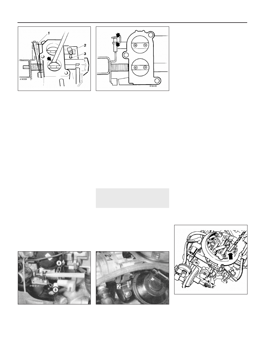
Throttle valve
6 The basic Stage ll throttle valve adjustment
is made during manufacture and should not
require further adjustment. If, for any reason,
the limiting screw has been removed or its
setting altered, readjust it as follows.
7 Open the throttle valve and hold it in
position by inserting a wooden rod or similar
implement between the valve and venturi (see
illustration). Using a rubber band, pretension
the Stage ll throttle valve locking lever then
unscrew the limiting screw to provide a
clearance between the stop and the limiting
screw. Now turn the limiting screw in so that it
is just in contact with the stop. The limiting
screw stop point can be assessed by inserting
a thin piece of paper between the stop and
screw. When the paper starts to get pinched
between the two, the stop point is reached
and from this point, tighten the limiting screw
a further quarter turn then secure it with
locking compound. Close both throttle valves
then measure the locking lever clearances
(see illustration). If the clearances are not as
specified, then bend the levers as necessary.
Slow running and fast idle
8 To check and adjust the slow running
setting, refer to Section 15, paragraphs 7 to
13 inclusive (see illustration).
9 To check and adjust the fast idle
adjustment, first check that the engine is still
at normal operating temperature. The air
cleaner must be removed and the other
provisional conditions must apply as for the
slow running adjustment. Plug the air cleaner
temperature control hose.
10 Restart the engine and open the throttle to
give an engine speed of approx. 2500 rpm.
Press down the fast idle cam to its stop then
move the throttle valve back so that the
adjuster screw is on the second highest stop
on the fast idle cam. In this position, the fast
idle speed should be as specified. If the
setting is incorrect, turn the adjustment screw
in the required direction until it is correct (see
illustration). Note that the screw may have a
tamperproof cap fitted.
11 On completion, unplug the temperature
control connector and refit the air cleaner.
17 Carburettor (1.6 & 1.8 litre
engines) - adjustments
4
Note: Accurate adjustment of the carburettor
is only possible if adjustment of the ignition
timing, dwell angle and spark plug gaps is
correct. Incorrect valve clearances can also
effect carburettor adjustment
Pierburg/Solex 2E2
1 The adjustment procedures for the 2E2
carburettor closely follow those described for
the 2E3 carburettor. The following checks and
adjustments are additional to, or differ from,
those given.
Part throttle channel heater unit
2 To check this unit, connect a test lamp
between the unit wiring plug and battery
positive terminal. Earth the unit. If the test
bulb fails to light, the unit is defective and
must be renewed.
Choke valve gap (wide open kick)
3 Remove the automatic choke cover and fit
a rubber band to the operating pin, so that the
choke valve is held in the closed position.
4 Hold the primary throttle valve open 45°. To
do this, temporarily insert a 10 mm nut
between the fast idling adjustment screw and
the vacuum unit plunger.
5 Using a twist drill, check that the gap
between the choke valve and carburettor wall
is 6.3 ± 0.3 mm. If not, bend the choke
operating lever as required (see illustration).
6 After making an adjustment, check and
adjust the choke pull-down unit as follows.
Choke pull down unit
7 This unit can be checked in the same
manner as that for the choke pull down unit
on the 2E3 carburettor but note that the
resistance felt must be over the final 5.0 mm
of travel.
8 Note also that from February 1987, the
choke pull-down unit is both temperature and
time-controlled by a thermotime valve. When
the valve is open (starting a cold engine) the
vacuum to the pull-down unit is reduced, and
the choke valve will open by a small amount.
After between one and six seconds
(depending on ambient temperature), the
valve heats up (to approximately 20 to 30°C)
and closes. This allows more vacuum to reach
the pull-down unit and the choke valve will
open by a larger amount. The choke is of
course fully released by the heat of the engine
coolant and the electric heater acting on the
automatic choke bi-metallic spring.
4A•18 Fuel and exhaust systems - carburettor models
16.7a Throttle valve basic setting showing
rod to hold valve open (arrowed), lock
lever (1) limiting screw (2) and stop (3)
16.7b Locking lever clearance with throttle
valves closed
Clearance to equal 0.25 to 0.55 mm
(each side)
16.8 Idle speed adjustment screw and
guide sleeve (A) mixture screw (B)
16.10 Fast idle speed adjustment screw (2)
17.5 Checking choke valve gap
Using drill of correct diameter as a gauge
(arrowed)
Note dimension x (10.0 mm)
1081 VW Golf & Jetta
Accelerator pump
9 To make this check, the carburettor must
be removed and you will need a vacuum
pump and an M8 x 20 mm bolt.
10 Detach the vacuum hoses from the
three/four point unit then connect up the
vacuum pump to the three/four point unit at
“A” (see illustration). Plug connection B (and
C on four point unit). Apply vacuum with the
pump to hold the diaphragm pushrod in the
overrun/cut-off position and to give a
clearance between the fast idle speed and
diaphragm pushrod.
11 Pivot the warm-up lever up to the point
where the throttle valve control pin has
clearance and insert the M8 x 20 mm bolt to
hold the warm-up lever in this position (see
illustration).
12 Hold the carburettor over a funnel and
measuring glass then slowly open the throttle
valve lever fully five times allowing at least 3
seconds per stroke. Divide the total quantity
by five and check the resultant injection
capacity against that specified.
13 If adjustment is necessary, loosen screw
A and rotate the cam plate B in the required
direction to increase or decrease the injection
capacity (see illustration). On completion,
retighten the screw and seal in position with
locking compound.
14 The accelerator pump injection capacity
can also be checked with the carburettor in
the vehicle but as specialised equipment is
required, this is a task best entrusted to your
VW dealer.
Throttle valve
15 For the basic Stage ll valve adjustment,
proceed as described in Section 16,
paragraphs 6 and 7 whilst referring to the
accompanying illustration (see illustration).
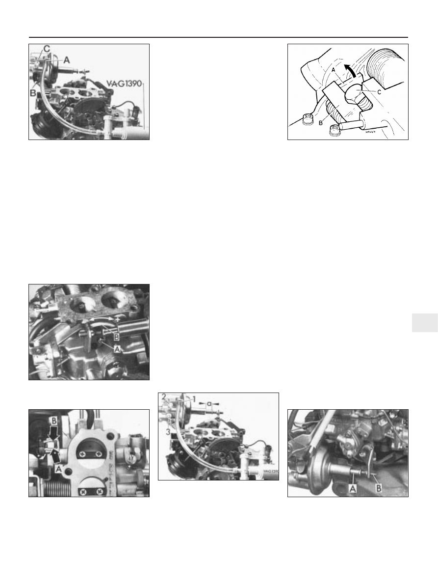
Three/four point unit - vacuum pump
method
16 Detach the vacuum hoses from the unit
and attach a vacuum pump to connection “1”
(see illustration). Apply vacuum to pull the
diaphragm pushrod to the idle point and then
measure the amount of rod protrusion, which
must be as specified.
17 To check the overrun cut-off point, plug
off the vacuum connection 3, then apply
increased vacuum with the vacuum pump.
This should cause the diaphragm pushrod to
move to the overrun/cut-off point. Measure
the rod protrusion (a) which should now be
1.0 mm. The pushrod should hold at this
position for one minute.
18 If rod protrusion is incorrect, or will not
hold for the specified period, then the
diaphragm or three/four point unit are
probably leaking and in need of renewal.
Three/four point unit - engine vacuum
method
19 Run the engine to normal operating
temperature then switch it off. Remove the air
cleaner and close the vacuum line from the
carburettor to the temperature regulator.
20 With the engine stopped, check the
diaphragm pushrod (A) (see illustration) is
fully extended to approximately 14.5 mm.
21 Start the engine and let it idle. The
diaphragm pushrod must now be extended
approximately 8.5 mm (three-point unit), or
9.5 mm (four-point unit), and must just
contact the fast idle adjustment screw.
22 On models with air conditioning, switch
on the air conditioner with the blower on
maximum speed. The diaphragm pushrod
dimension should be approximately 12.0 mm.
23 To check the overrun cut-off point, run the
engine at idle speed.
24 On the four-point unit, disconnect and
plug the pink-coloured hose at the control
valve.
25 Using a screwdriver, hold the primary
throttle valve fully closed to prevent it moving
to the overrun cut-off point.
26 Disconnect the plug from the
idling/overrun control valve, then check that
the diaphragm pushrod dimension is
approximately 1.5 mm.
27 To check the unit for leaks, first, on the
three-point unit only, pinch the hose between
the unit and Y-piece.
Fuel and exhaust systems - carburettor models 4A•19
4A
17.10 Accelerator pump check
preparation
A Vacuum pump connection
B Plug vacuum connection (3-point unit)
C Plug vacuum connection (4-point unit)
17.11 Accelerator pump adjustment check
showing warm-up lever (A) lever (B) and
bolt (C)
17.13 Loosen screw (A) and turn cam plate
(B) in direction required to adjust
accelerator pump injection capacity
17.15 Lock lever clearance with throttle
valves closed
17.16 Three or four point unit check
preparation
Pushrod to idle point a = 8.5 mm
1 Vacuum connection
2 and 3 Plug these connections
17.20 Three/four point unit with pushrod
(A) and cold idling adjusting screw (B) in
idling position
1081 VW Golf & Jetta
28 Stop the engine by disconnecting the coil
terminal 15, and check that the diaphragm rod
remains in the overrun/cut-off position for a
minimum of five seconds.
29 Reconnect the coil wiring, control valve
plug and hose where applicable. Refit the air
cleaner.
Stage ll vacuum control unit
30 This device is fitted to 1.6 litre manual
gearbox models and 1.8 automatic gearbox
models from August 1984 on. Its function is to
delay the Stage ll opening slightly whilst the
coolant temperature is below 18°C. It
achieves this by venting the vacuum hose via
the thermo-pneumatic valve and the resistor
(see illustration).
31 Check that the straight hose at connection
3 on the thermo-pneumatic valve is not
blocked and check the valve itself by blowing
through it. It should be open at 18°C and close
when the temperature rises above 28°C.
Idle/overrun control valve
32 Entrust this operation to your VW dealer as
specialised testing equipment is necessary.
Temperature time valve
33 Entrust this operation to your VW dealer
as specialised testing equipment is
necessary.
Slow running and fast idle
34 To check and adjust the slow running
setting, proceed as described in Section 15,
paragraphs 7 to 13 inclusive whilst noting the
following differences:
a) Before making any adjustments, ensure
that the three/four point unit pushrod is in
the idling position with the cold idling
adjusting screw touching the pushrod
b) If adjustment is necessary, turn the idling
speed control valve and CO adjustment
screw (see illustrations), as necessary.
c) Access to the CO adjustment screw is
gained by prising out the tamperproof
plug. If the CO content is difficult to
adjust, remove the adjustment screw and
clean its point, then refit and adjust it
35 On automatic transmission models, the
increased idling speed can be checked and
adjusted as follows. In addition to those
preliminary requirements necessary when
checking the idle speed slow running setting,
the hand brake must be fully applied and
chocks placed against the wheels.
36 When the engine is started, turn on the
fresh air blower (fully), switch on the headlights
(high beam) and the heated rear window. Get
an assistant to sit in the vehicle and depress
the foot brake then select D. Check that the
four point unit diaphragm rod is in the
increased idling position, the fast idle adjuster
screw rests against the diaphragm rod and the
engine increased idle speed is not under that
specified. Adjust if necessary by altering the
regulator valve setting (see illustration).
37 On models fitted with air conditioning, the
procedure for checking the increased idling
speed is similar to that for automatic
transmission models except that it is also
necessary to switch on the air conditioner and
have the control set at maximum cooling at
the highest blower speed. The increased idle
speed must be as specified and if adjustment
is required, alter the regulator valve setting
accordingly.
38 With the slow/increased running idle
speed adjustment complete, the fast idle
speed can be checked and, if necessary,
adjusted. Check that the engine is still at its
normal operating temperature.
39 Detach the Y-piece from the vacuum hose
and plug the hose (see illustration). Connect
a tachometer to the engine. Start and run the
engine and check that the fast idle speed is as
specified. If not, turn the adjustment screw on
the linkage as necessary (see illustration). On
completion of adjustment, apply sealant to
the screw threads to lock it in position, unplug
and reconnect the Y-piece to the vacuum
hose and check that the slow running (idle)
speed is as specified.
18 Inlet manifold preheating -
testing
2
Heater element
1 The inlet manifold is preheated by coolant
from the cooling system and by a heater
element located in the bottom of the inlet
manifold.
4A•20 Fuel and exhaust systems - carburettor models
17.30 Stage II vacuum unit control
1 Thermo-pneumatic valve
2 Restrictor
3 Straight connection hose
17.34a Idling speed control valve (A)
17.34b Mixture (CO) adjustment screw (A)
17.36 Engine speed regulator valve (1)
17.39a Disconnect and plug vacuum hose
(1) to check/adjust engine fast idle speed
adjustment
17.39b Fast idle adjustment screw (A)
1081 VW Golf & Jetta
2 To check the heater element, the engine
should be cold. Disconnect the wire from the
element at its in-line connector, then attach an
ohmmeter between the wire connector from
the element and earth. This should record
0.25 to 0.50 ohm.
3 To remove the element, disconnect the wire
then unscrew the bolts and withdraw the unit.
Remove the sealing ring and gasket (see
illustrations). When refitting, always renew
the sealing ring and gasket.
Thermo-switch
4 On 1.05 and 1.3 litre engines, the heater
element is controlled by a thermo-switch
located in the coolant supply hose to the inlet
manifold. On 1.6 and 1.8 litre engines, the
thermo-switch is located in the top of the
coolant hose connecting piece mounted on
the side of the cylinder head.
5 Before removing the thermo-switch, drain
off some engine coolant to reduce spillage
when the switch is removed.
6 To test the thermo-switch, first detach the
lead connector. Unscrew and remove the
switch from the housing and plug the hole to
stop any leakage of coolant.
7 With an ohmmeter connected to the
terminals, gradually heat the base of the
switch unit in hot water. Below the following
temperatures there should be zero resistance
(ie. internal contacts closed):
1.05 litre engine - 65°C
1.3, 1.6 and 1.8 litre engines - 55°C
8 Above the following temperatures there
should be a maximum resistance (ie. internal
contacts open):
1.05 litre engine - 75°C
1.3, 1.6 an d 1.8 litre engines - 65°C
9 If defective, the switch must be renewed.
19 Inlet and exhaust manifolds -
removal and refitting
3
Inlet manifold
1 Remove the carburettor.
2 Disconnect the inlet manifold preheater
wire at the in-line connector.
3 Drain the cooling system and disconnect
the coolant hoses from the manifold.
4 Disconnect the manifold vacuum hoses as
necessary (see illustration).
5 Where applicable, disconnect the stay rod
between the base of the manifold and the
crankcase (see illustration).
6 Undo the manifold retaining nuts and bolts
(see illustration) whilst noting their respective
Fuel and exhaust systems - carburettor models 4A•21
4A
18.3a Unscrew the bolts . . .
18.3b . . . and remove heater element from
inlet manifold
18.3c Removing sealing ring from heater
element
1081 VW Golf & Jetta
19.4 Vacuum hose connections – 1.6 and 1.8 litre with
Pierburg/Solex 2E2 carburettor
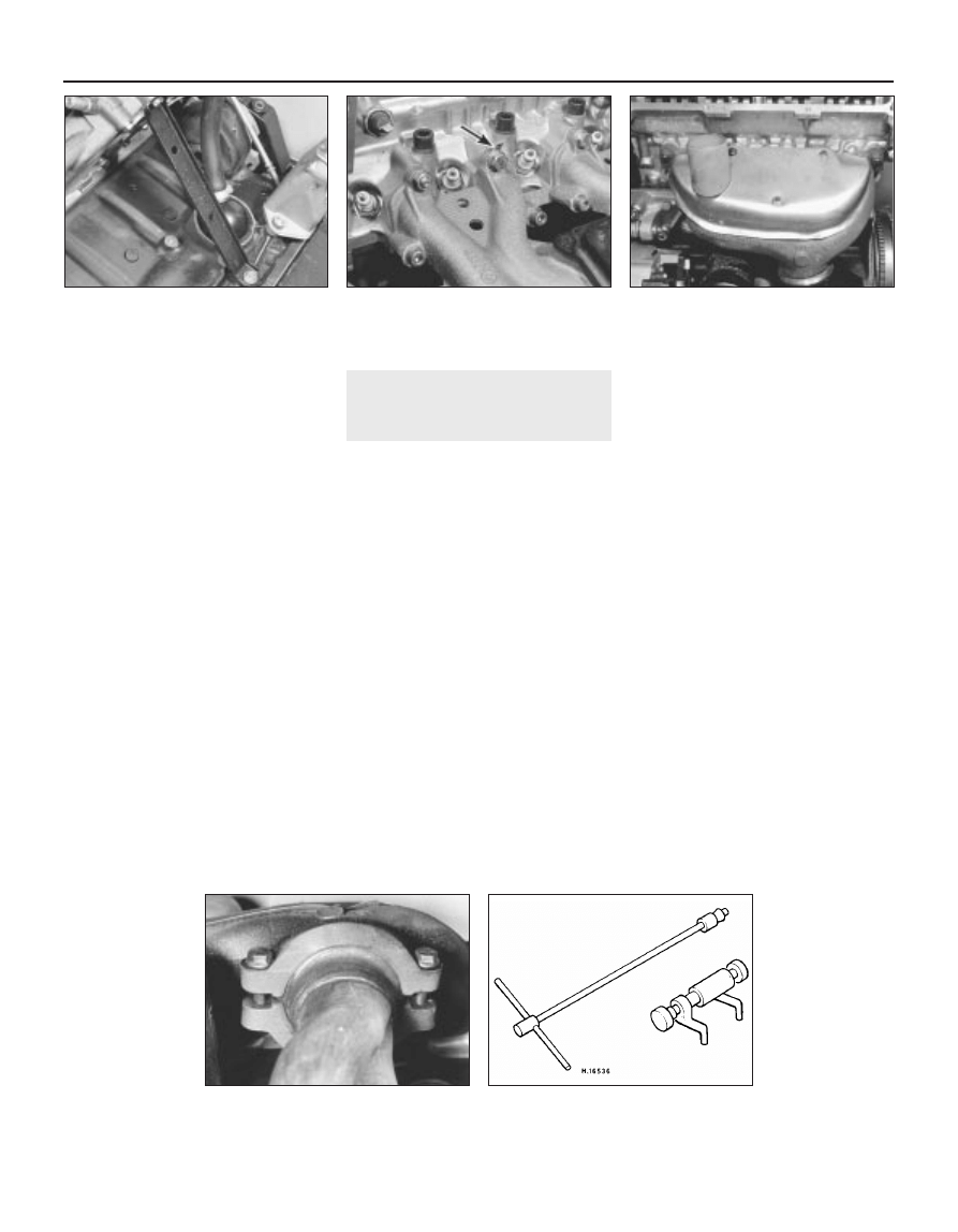
locations, then carefully withdraw the
manifold from the cylinder head.
7 Remove the gasket and clean the mating
faces of the manifold and cylinder head.
8 Refitting is a reversal of the removal
procedure. Use a new manifold gasket and
tighten the securing nuts and bolts to the
specified torque setting.
Exhaust manifold
9 Undo the retaining nut(s) and withdraw the
warm air deflector plate from the exhaust
manifold (see illustration).
10 On 1.05 and 1.3 litre engines, unbolt and
detach the exhaust downpipe from the
manifold joint (see illustration).
11 On 1.6 and 1.8 litre engines, refer to
Section 20, paragraph 2.
12 Unscrew and remove the remaining
manifold retaining bolts/nuts, then carefully
withdraw the manifold from the cylinder head.
Remove the gasket.
13 Clean the mating faces of the manifold
and cylinder head. Also the exhaust downpipe
flange connections.
14 Refit in the reverse order of removal. Use
a new gasket and tighten the securing
nuts/bolts evenly to the specified torque
wrench setting.
15 When reconnecting the downpipe to the
manifold, smear a little exhaust jointing paste
onto the flange prior to connection. This will
ensure a good seal at the joint.
20 Exhaust system - inspection,
removal and refitting
3
Inspection
1 Refer to Chapter 1, Section 19
Removal
2 On 1.6 and 1.8 litre engines, it should be
noted that if the exhaust system is to be
separated at the manifold/downpipe
connection, then VW tool No. 3049A will be
necessary to release and subsequently refit
the joint retaining clips (see illustration).
Without this tool, it is virtually impossible to
separate and reassemble the joint without
distorting the retaining clips. In view of this,
removal and refitting of the system will
necessitate detachment of the manifold and
front pipe section, or manifold and system
complete, and then taking the assembly to
your VW dealer to separate/reassemble the
front joint. If the complete system is in need of
replacement, it is probably best entrusted to
your VW dealer.
3 On 1.05 and 1.3 litre engines, when
removing any part of the exhaust system it is
usually easier to undo the manifold-to-front
pipe joint and remove the complete system
from the vehicle, then separate the various
pieces of the system, or cut out the defective
part with a hacksaw.
4 Before doing any dismantling work on the
exhaust system, wait until the system is cool
and then saturate all bolts and joints with a
proprietary anti-corrosion fluid (see
illustrations). It may be found easier to cut
through heavily corroded bolts with a
hacksaw, rather than try to unscrew them.
Refitting
5 Refit the system a section at a time starting
at the front. If the manifold has been removed
its gasket must be renewed. New nuts and
bolts should be used throughout the system.
6 Before assembly, smear all joints with a
proprietary exhaust sealing compound. This
makes it easier to align the pieces and also
ensures that the joints will be gas tight. Leave
all bolts loose.
7 Run the engine until the exhaust system is
at normal temperature and then, with the
engine running at idling speed, tighten all the
mounting bolts and clips, starting at the
manifold and working towards the rear
silencer. Take care to avoid touching any part
of the system with bare hands because of the
danger of painful burns.
8 With all bolts and clips tightened, it is
important to ensure that there is no strain on
any part of the system.
4A•22 Fuel and exhaust systems - carburettor models
19.5 Inlet manifold support stay - 1.3 litre
19.6 Inlet manifold-to-cylinder head
securing nuts and bolts
Note position of earth lead spade connector
(arrowed) - 1.3 litre
19.9 Warm air deflector plate - 1.3 litre
19.10 Exhaust downpipe-to-manifold
flange connection - 1.3 litre
20.2 VW tool 3049A used to release and fit
exhaust downpipes to manifold clips -
1.6 and 1.8 litre
1081 VW Golf & Jetta
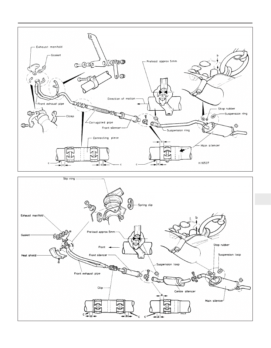
Fuel and exhaust systems - carburettor models 4A•23
4A
1081 VW Golf & Jetta
20.4b Exhaust system and associated components – 1.6 and 1.8 litre
Connecting piece and clamp setting dimensions
a = 5.0 mm
b = 12.0 mm
c Marking (S for manual gearbox or A for automatic
transmission)
20.4a Exhaust system and associated components – 1.5 and 1.3 litre
Connecting piece and clamp setting dimensions
a = 5.0 mm
b = 12.0 mm
c Marking (S)

4A•24
1081 VW Golf & Jetta
Notes
Wyszukiwarka
Podobne podstrony:
husqvarna gaźnik
Gaźnik1
Piła spalinowa gaźnik
Gaźnik
gaznik
gaznik www prezentacje org
instrukcja obslugi gaznika do skutera 4 t (www instrukcja pl)
odparowanie benzyny w gaźnikach
gaźnik NB 22-1, Motocykle, Motocykle zagraniczne, Motocykl IFA BK 350
zasady ustawiania gaźnika
Synchronizacja gaźników, Motocykle, Pozostałe
Regulacja gaźnika Aisan w Cinquecento 700, Mechanika, gaźniki
Gaźnik1
Budowa pojazdów samochodowych układ gaźnikowy
husqvarna gaźnik
Regulacja gaźnika Aisan CC 700, Naprawa CINQUECENTO
budowa gaźnika D13B2
Niva gaźnik
więcej podobnych podstron