+<'5$8/,& 6<67(0
$1' *($5 3803
$66(0%/<
H1.50-1.75XM (S/H25-35XM)
[C010, D001, D010, E001],
H2.00XMS (S/H40XMS)
[C010, D001, D010, E001]
PART NO. 897553
1900 SRM 539

SAFETY PRECAUTIONS
MAINTENANCE AND REPAIR
• When lifting parts or assemblies, make sure all slings, chains, or cables are correctly
fastened, and that the load being lifted is balanced. Make sure the crane, cables, and
chains have the capacity to support the weight of the load.
• Do not lift heavy parts by hand, use a lifting mechanism.
• Wear safety glasses.
• DISCONNECT THE BATTERY CONNECTOR before doing any maintenance or repair
on electric lift trucks.
• Disconnect the battery ground cable on internal combustion lift trucks.
• Always use correct blocks to prevent the unit from rolling or falling. See HOW TO PUT
THE LIFT TRUCK ON BLOCKS in the Operating Manual or the Periodic Mainte-
nance section.
• Keep the unit clean and the working area clean and orderly.
• Use the correct tools for the job.
• Keep the tools clean and in good condition.
• Always use HYSTER APPROVED parts when making repairs. Replacement parts
must meet or exceed the specifications of the original equipment manufacturer.
• Make sure all nuts, bolts, snap rings, and other fastening devices are removed before
using force to remove parts.
• Always fasten a DO NOT OPERATE tag to the controls of the unit when making repairs,
or if the unit needs repairs.
• Be sure to follow the WARNING and CAUTION notes in the instructions.
• Gasoline, Liquid Petroleum Gas (LPG), Compressed Natural Gas (CNG), and Diesel fuel
are flammable. Be sure to follow the necessary safety precautions when handling these
fuels and when working on these fuel systems.
• Batteries generate flammable gas when they are being charged. Keep fire and sparks
away from the area. Make sure the area is well ventilated.
NOTE:
The following symbols and words indicate safety information in this
manual:
WARNING
Indicates a condition that can cause immediate death or injury!
CAUTION
Indicates a condition that can cause property damage!
1900 SRM 539
Description and Operation
General
This section has a description of the hydraulic sys-
tem, pump drive, and gear pump assembly. Proce-
dures for the repair of the pump drive and gear pump
assembly are also in this section.
Repair information for the parts of the steering sys-
tem are in the sections Steering Axle 1600 SRM
532 and Steering Housing and Control Unit 1600
SRM 720. Information on the control valve is in the
section Main Control Valve 2000 SRM 541.
Gear Pump Flow Check and Troubleshooting for the
gear pump assembly are at the end of this section.
Description and Operation
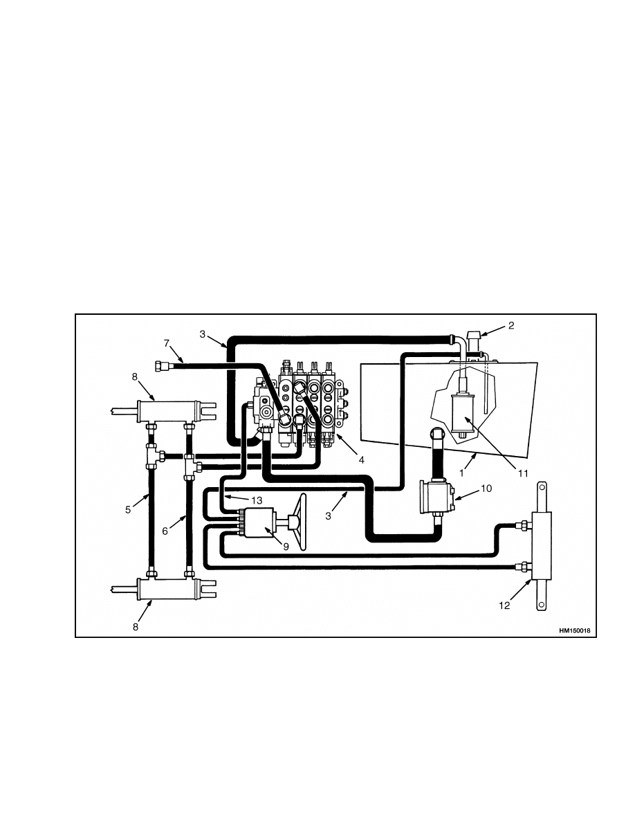
HYDRAULIC SYSTEM
The hydraulic system has the following parts: hy-
draulic tank, gear pump assembly, pump drive shaft,
steering control unit, main control valve, lift cylin-
ders, tilt cylinders, steering cylinder, oil filter, and
breather. See Figure 1. The steering system and
the lift and tilt system are common circuits of the hy-
draulic system, using a common hydraulic tank and
gear pump. A breather at the top of the tank lets air
into the hydraulic tank.
1.
HYDRAULIC TANK
2.
BREATHER
3.
RETURN LINE
4.
MAIN CONTROL VALVE
5.
TILT BACKWARD LINE
6.
TILT FORWARD LINE
7.
TO LIFT CYLINDERS
8.
TILT CYLINDER
9.
STEERING CONTROL UNIT
10. HYDRAULIC PUMP
11. FILTER
12. STEERING CYLINDER
13. STEERING SUPPLY LINE
Figure 1. Hydraulic System
1
Description and Operation
1900 SRM 539
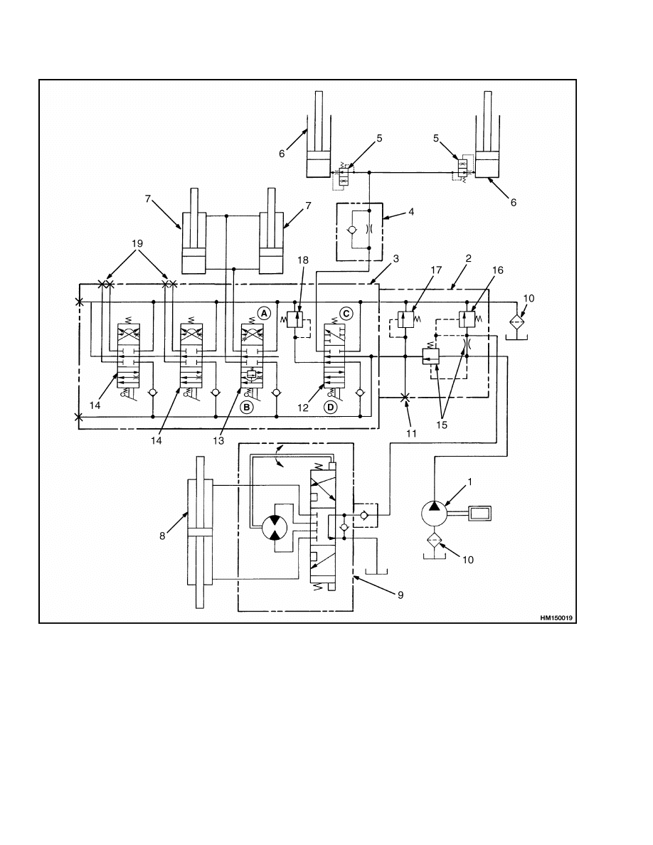
A. FORWARD
B. BACK
C. LIFT
D. LOWER
1.
HYDRAULIC PUMP
2.
FLOW DIVIDER SECTION
3.
SPOOL SECTIONS (LIFT, TILT,
AND AUXILIARY)
4.
LOWERING CONTROL VALVE
(ON MAST)
5.
LOWERING CONTROL VALVE
(AT CYLINDER PORT)
6.
LIFT CYLINDER
7.
TILT CYLINDER
8.
STEERING CYLINDER
9.
STEERING CONTROL VALVE
10. FILTER
11. PRESSURE CHECK PORT
12. LIFT/LOWER SPOOL
13. TILT SPOOL
14. AUXILIARY SPOOL
15. FLOW CONTROL VALVE
16. RELIEF VALVE (STEERING
SYSTEM)
17. MAIN RELIEF VALVE
18. RELIEF VALVE (TILT &
AUXILIARY CIRCUITS)
19. AUXILIARY FUNCTION PORTS
Figure 2. Hydraulic System Schematic
2
1900 SRM 539
Description and Operation
The gear pump sends oil flow to the steering system
and the lift and tilt system. The gear pump receives
oil from the hydraulic tank through a screen at the
outlet of the tank. The oil from the pump flows di-
rectly to the flow divider. The flow divider supplies
a constant supply of oil to the steering system. This
quantity of oil flow is controlled by the steering con-
trol unit to operate the steering cylinder. The re-
lief valve in the inlet cover limits the pressure in the
steering system.
The secondary flow from the pump goes to the main
control valve. This valve controls the flow of oil to the
lift, tilt, and any auxiliary functions. A relief valve in
the end cover limits the pressure in the hydraulic sys-
tem. In some configurations, the auxiliary functions
can be controlled by separate relief valves. Test ports
permit checking the relief pressures of each system.
The location of the test ports is shown in Figure 2.
The oil returning from the main control valve flows
through a filter in the return line to the hydraulic
tank.
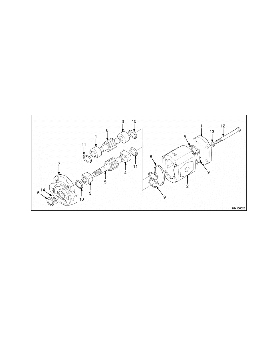
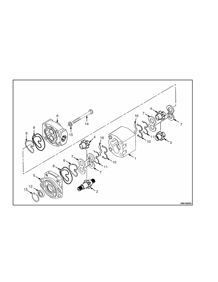
GEAR PUMP ASSEMBLY
The gear pump can have either one or two sets of
gears. See Figure 3 and Figure 4. The pump with two
sets of gears reduces hydraulic noise. Seals between
the sections prevent leaks to outside of the pump.
The gear pump is driven by a shaft connected to the
pulley on the engine crankshaft.
1.
COVER
2.
BODY
3.
BEARING
4.
BEARING
5.
GEAR
6.
GEAR
7.
FLANGE
8.
OIL SEAL
9.
OIL SEAL
10. BACKUP RING
11. BACKUP RING
12. BOLT
13. LOCKWASHER
14. OIL SEAL
15. SNAP RING
Figure 3. Gear Pump Assembly (Single Gearset Hydraulic Pump)
3
Description and Operation
1900 SRM 539
The gears in the pump have their teeth engaged in
the center of the pump body. The pump has close tol-
erances between the teeth and the pump body. When
the input shaft is turned, the drive gear turns the
driven gear. The tolerances and seals make tight
chambers between the gear teeth. When the teeth
of each gear move apart at the inlet port, they make
a vacuum. Oil from the tank enters the inlet port and
is moved around the circumference of the gear by the
chambers between the gear teeth. Passages opposite
the inlet connect the gear chambers for outlet oil flow
to the flow control valve. Oil lubricates the bearings
and the gear surface of each bearing. Oil at the in-
let flows through bores and passages in the bearings
(pressure plates on some models) to both sides of each
bearing. Other bores and passages in the bearings
let the outlet oil pressure go to the sides of the bear-
ing away from the gears. The passages also let this
outlet oil flow to the side of the inlet circumference
of each bearing to balance the pressure on the bear-
ings. The outlet pressure on the gears puts a force on
the bearings to keep them tight against the gears for
better pump efficiency and to allow for wear.
1.
BODY
2.
DRIVE GEAR
3.
DRIVE GEAR
4.
DRIVEN GEAR
5.
FLANGE
6.
END COVER
7.
PRESSURE PLATE
8.
SEAL
9.
BACKUP RING
10. BUSHING SEAL
11. BACKUP SEAL
12. SEAL
13. SNAP RING
14. CAPSCREW
15. WASHER
16. ISOLATION PLATE
Figure 4. Gear Pump Assembly (Dual Gearset Hydraulic Pump)
4

1900 SRM 539
Description and Operation
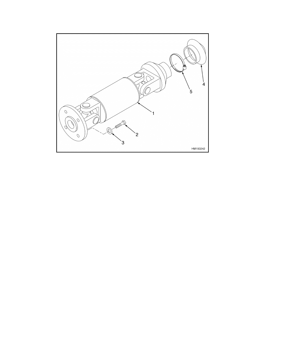
PUMP DRIVE SHAFT
One end of the pump drive shaft is attached to the
end of the crankshaft with a yoke and four bolts. See
Figure 5 or Figure 6. The other end of the pump drive
shaft is attached to the pump shaft with a coupling
that has splines. The shaft has a lube fitting that
must be lubricated according to the schedule in the
Periodic Maintenance section for your lift truck.
NOTE: ARRANGEMENT FOR DIESEL ENGINE SHOWN.
1.
YOKE
2.
YOKE
3.
CROSS
4.
SNAP RING
5.
BOLT
6.
LOCKWASHER
7.
COUPLING
8.
BOLT
9.
NUT
10. BOLT
11. COUPLING
12. PLUG
13. GREASE FITTING
14. BOOT
15. STRAP CLAMP
Figure 5. Pump Drive Shaft (Earlier Models)
5
Description and Operation
1900 SRM 539
1.
SHAFT
ASSEMBLY
2.
CAPSCREW
3.
WASHER
4.
BOOT
5.
STRAP CLAMP
Figure 6. Pump Drive Shaft (Later Models)
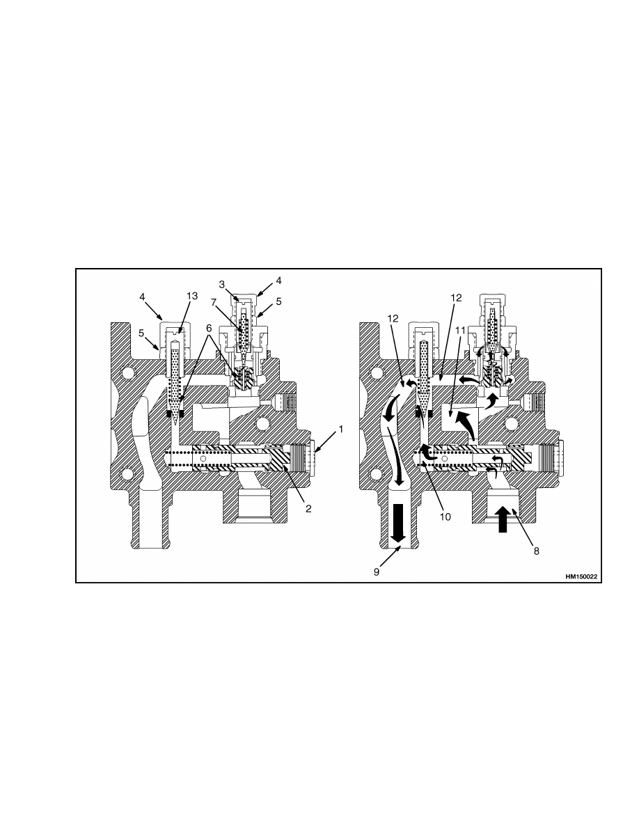
STEERING FLOW DIVIDER
The flow divider for the steering system is in the inlet
cover on the main control valve. The flow control
valve ensures that the steering system has a constant
supply of oil. See Figure 7. The flow control valve
has a spring, a plunger with an orifice, and a plug
with an O-ring. The spring keeps the plunger in the
correct position. Oil pressure can move the plunger
and compress the spring. The plug keeps the plunger
and spring in the bore and also keeps the oil in the
correct chamber.
The oil from the pump enters the valve chamber near
the center of the plunger. The oil flows through the
orifice in the plunger to the steering system port.
This oil also flows to the main hydraulic supply and
the relief valve. If the oil flow from the pump is more
than the primary flow for the steering system, the
flow control spool will move. This plunger movement
connects part of the oil flow to the lift and tilt system
port. The plunger will also move back and decrease
or stop the flow of oil to the lift and tilt system if the
pump flow decreases. The plunger keeps moving to
make sure the steering system always has a constant
supply of oil.
RELIEF VALVE (STEERING)
The relief valve for the steering system is in the inlet
cover on the main control valve. See Figure 7. The
relief valve prevents the oil pressure in the steering
system from increasing above specifications. The re-
lief valve has the following parts: a valve seat, a pop-
pet, a spring, a plunger, an adjuster, a lock nut, two
gaskets, and a cap. The position of the adjuster and
the amount of compression of the spring determine
the relief pressure. When the adjustment is correct,
the lock nut will hold the adjuster in the correct loca-
tion, the cap will protect the adjusting nut, and the
gaskets will seal the lock nut against the end cover
and the cap against the lock nut.
The pressure in the steering system is sensed at the
relief valve. If the pressure increases to the relief
valve setting, the poppet in the relief valve will move
against the spring. When the poppet moves off the
seat, oil flows through an internal passage that di-
rects the oil flow to the oil tank to decrease the pres-
sure. The decrease in pressure lets the spring return
the poppet back to the seat.
6
1900 SRM 539
Description and Operation
RELIEF VALVE (MAIN HYDRAULIC)
The relief valve for the main hydraulic system is in
the inlet cover on the main control valve. See Fig-
ure 7. The relief valve prevents the oil pressure in the
main hydraulic system from increasing above speci-
fications. The relief valve has the following parts: a
valve seat, a relief valve poppet, a spring, a pilot pop-
pet, a pilot spring, an adjuster, a lock nut, two gas-
kets, and a cap. The position of the adjuster and the
amount of compression of the spring determine the
relief pressure. When the adjustment is correct, the
lock nut will hold the adjuster in the correct location,
the cap will protect the adjusting nut, and the gas-
kets will seal the lock nut against the end cover and
the cap against the lock nut.
The pressure in the main hydraulic system is sensed
at the relief valve. If the pressure increases to the re-
lief valve setting, the pilot poppet moves against the
pilot spring. When the small oil flow through the ori-
fice of the pilot poppet occurs, a decrease in pressure
occurs across the relief valve. This difference in pres-
sure moves the relief valve poppet off the seat. When
the poppet moves off the seat, oil flows through an in-
ternal passage that directs the oil flow to the oil tank
to decrease the pressure. The decrease in pressure
lets the spring return the poppet back to the seat.
1.
PLUG
2.
FLOW CONTROL SPOOL
3.
MAIN RELIEF ADJUSTER
4.
CAP
5.
LOCK NUT
6.
POPPET
7.
PLUNGER
8.
SUPPLY FLOW
9.
RETURN FLOW
10. STEERING SUPPLY
11. MAIN HYDRAULIC SUPPLY
12. RELIEF FLOW
13. STEERING RELIEF ADJUSTER
Figure 7. Flow Control Valve and Relief Valve Operation
7

Pump Drive Shaft Repair
1900 SRM 539
Gear Pump Assembly Repair
REMOVE AND DISASSEMBLE
NOTE:
Worn or damaged seals are the most common
cause of pump damage. The pump bushings, gears,
and shafts also wear. They must be checked during
disassembly. Do not make any repairs to the parts.
To prevent more failures, always replace parts that
are worn or damaged. If several main parts need
replacing, replace the complete group.
1.
Remove counterweight. See section Frame 100
SRM 545 for correct procedure.
2.
Put a drain pan under pump assembly. Discon-
nect suction line and pressure hose at pump.
Plug suction line and pressure hose. See Fig-
ure 3 and Figure 4.
3.
Hold pump assembly to keep it from falling. Re-
move two capscrews, nuts, and washers that fas-
ten pump to mounting bracket. Remove pump
assembly.
4.
Put pump body into a vise. Do not damage inlet
port. Put alignment marks on three sections of
pump.
5.
Remove capscrews that hold pump together. Re-
move end cover. Remove body assembly. Do not
let seals and gears fall.
6.
Note position of seals.
Carefully remove oil
seals, pressure plates, bushings, and gears from
housings. Remove snap ring and shaft seal from
flange end housing.
7.
Check parts for wear and damage.
ASSEMBLE AND INSTALL
1.
Put clean hydraulic oil on all parts of pump and
valves. Use hydraulic oil shown in the Periodic
Maintenance section for your lift truck. Be sure
to keep parts clean. See Figure 3 and Figure 4.
2.
Use new seals and install bushings and gears
into flange end housing. See notes made during
disassembly. Make sure all seals are complete
and in correct positions.
3.
Install new oil seal in flange end housing. Install
body assembly. Make sure seals do not move out
of correct position.
4.
Install new seals in end cover end of pump.
Carefully install end cover on pump body using
the four capscrews and lockwashers. Make sure
seals stay in correct position. Make sure marks
made during disassembly are aligned. Tighten
capscrews.
5.
Engage pump drive shaft with splines on pump.
Hold pump in correct position on mounting
bracket. Install capscrews, nuts, and washers
that fasten pump to mounting bracket.
6.
Connect hydraulic lines. Do not tighten inlet fit-
ting. Fill tank with hydraulic oil. Let some of oil
run out around pump inlet fitting. Tighten fit-
tings. This procedure will ensure pump has oil
for first operation.
7.
Install counterweight. See section Frame 100
SRM 545 for correct procedure.
Pump Drive Shaft Repair
DISASSEMBLE
WARNING
Be careful when removing or installing snap
rings. Snap rings can come loose during re-
moval or installation with enough force to
cause an injury. Always use the correct snap
ring pliers and wear eye and face protection
during removal or installation.
NOTE:
This procedure is for earlier model pump
drive shafts only. On later model pump drive shafts,
only the boot, the strap clamp, and the entire shaft
assembly can be replaced.
The cross must be pressed in and out in a vise. The
following tools are needed to remove the spiders:
• A steel tube approximately 38 mm (1.5 in.) long
with an inside diameter that is larger than the out-
side diameter of the spider bearing
• A steel rod approximately 8 mm (0.33 in.) in diam-
eter and 38 mm (1.5 in.) long
1.
Remove snap rings that hold spider in yoke. See
Figure 5.
8

1900 SRM 539
Gear Pump Flow Check
2.
Put rod against one end of spider and tube at
opposite end. Tube must be positioned so that
spider bearing will fit inside tube.
3.
With rod against one vise jaw and tube against
other, slowly close vise to press spider into tube.
4.
When spider is free from yoke, remove bearings
from spider and spider from yoke.
ASSEMBLE AND INSTALL
1.
Place spider inside yoke. Put bearings onto yoke.
See Figure 3 and Figure 4.
2.
Use a vise to press bearings together. Make sure
spider is properly positioned between bearings.
Rod must be used to completely press bearings
into yoke.
3.
Install snap rings.
4.
Tighten attaching bolts and assembly bolts to 21
to 25 N•m (15 to 18 lbf ft).
Steering Relief Pressure Check and Adjust
1.
Connect tachometer to engine.
2.
Remove test port plug on control valve. Connect
needle valve and pressure gauge to test port. See
Figure 1 and Figure 2.
3.
Operate engine at 700 rpm. Operate hydraulic
system until oil temperature is 55 to 65 C (130
to 150 F). Turn steering wheel to stop and hold
in that position.
4.
Check pressure gauge.
The correct pressure
reading is 5.4 to 5.9 MPa (783 to 858 psi).
5.
If pressure is less than specification, remove
cap, loosen lock nut, and turn adjuster for relief
valve clockwise. See Figure 7. If pressure is
higher than specification, turn adjuster counter-
clockwise. After setting is correct, hold adjuster,
tighten lock nut, and install cap.
6.
Remove pressure gauge, needle valve, and
tachometer. Install test port plug.
Gear Pump Flow Check
NOTE:
Make sure the hydraulic oil is at operating
temperature of 35 to 65 C (100 to 150 F).
1.
Install flow meter in outlet line of gear pump.
Follow manufacturer’s recommended procedure
for operation.
2.
Check output of gear pump. For gasoline and
LPG engines, the correct rate for priority flow is
45.8 liter/min (12.1 gal/min) at 2000 rpm. For the
diesel engine, the correct rate for priority flow is
66.6 liter/min (17.6 gal/min) at 2000 rpm.
9

Troubleshooting
1900 SRM 539
Troubleshooting
PROBLEM
POSSIBLE CAUSE
PROCEDURE OR ACTION
The output of the pump is
less than specifications.
See Possible Cause for "The pump
makes more noise than normal."
See Procedure or Action for "The
pump makes more noise than nor-
mal."
The pressure for the steer-
ing system is below specifi-
cations.
The relief valve is not adjusted cor-
rectly.
Adjust or install new relief valve.
The relief valve is damaged.
Repair or install new relief valve.
The pump is worn.
Repair or install new pump.
The flow for the steering sys-
tem is below specifications.
The flow control valve is not operat-
ing correctly.
Repair or install new flow control
valve.
The relief valve is not adjusted cor-
rectly.
Adjust or install new relief valve.
The pump makes more noise
than normal.
The oil level is not correct or there is
no oil in the tank (cavitation).
Check oil level and fill as required.
Check for leaks.
The incorrect type or grade of hy-
draulic oil is used for the tempera-
ture or type of operation (cavitation).
Check, drain, and fill tank with the
correct oil.
The suction screen has a restriction
(cavitation).
Clean or install new screen.
The inlet fitting is loose or hose leaks
are allowing air to enter the system
(aeration).
Tighten fitting.
Install new hoses.
Remove air from the system.
The pump bearings or gears are
damaged.
Repair or install new pump.
The capscrews that hold the pump
together are loose.
Tighten capscrews to the specified
torque.
The pump is loose.
Tighten fasteners to the specified
torque.
The pump drive mechanism is loose,
worn, or damaged.
Check, repair, or install new parts as
required.
10

1900 SRM 539
Troubleshooting
PROBLEM
POSSIBLE CAUSE
PROCEDURE OR ACTION
The pump has leaks.
The fittings or hoses on the outlet
side of the pump are loose or dam-
aged.
Tighten fittings. Install new parts as
necessary.
The capscrews that hold the pump
together are loose.
Tighten capscrews to the specified
torque.
The seals in the pump are damaged.
Install new seals or new pump.
11

NOTES
____________________________________________________________
____________________________________________________________
____________________________________________________________
____________________________________________________________
____________________________________________________________
____________________________________________________________
____________________________________________________________
____________________________________________________________
____________________________________________________________
____________________________________________________________
____________________________________________________________
____________________________________________________________
____________________________________________________________
____________________________________________________________
____________________________________________________________
____________________________________________________________
____________________________________________________________
____________________________________________________________
____________________________________________________________
____________________________________________________________
12

TECHNICAL PUBLICATIONS
1900 SRM 539
2/01 (11/94)(8/93) Printed in U.S.A.
Document Outline
- General
- Description and Operation
- Gear Pump Assembly Repair
- Pump Drive Shaft Repair
- Steering Relief Pressure Check and Adjust
- Gear Pump Flow Check
- Troubleshooting
Wyszukiwarka
Podobne podstrony:
897509 2200SRM0524 (02 2001) UK EN
910107 2200SRM0106 (02 2001) UK EN
897594 2200SRM0550 (02 2001) UK EN
897590 8000SRM0546 (02 2001) UK EN
1564283 1900SRM1107 (01 2004) UK EN
910091 1900SRM0097 (08 2005) UK EN
1598459 1900SRM1213 (03 2005) UK EN
897394 1900SRM0453 (09 2003) UK EN
1538373 2200SRM1065 (02 2004) UK EN
897956 1900SRM0642 (03 2005) UK EN
897393 1800SRM0452 (02 2004) UK EN
1470232 1900SRM0783 (01 2004) UK EN
1566279 8000SRM1155 (02 2005) UK EN
897591 0900SRM0547 (02 2001) US EN
więcej podobnych podstron