STARTER
DELCO
DELCO STARTERS USED ON HYSTER
LIFT TRUCKS
PART NO. 910107
2200 SRM 106

SAFETY PRECAUTIONS
MAINTENANCE AND REPAIR
• When lifting parts or assemblies, make sure all slings, chains, or cables are correctly
fastened, and that the load being lifted is balanced. Make sure the crane, cables, and
chains have the capacity to support the weight of the load.
• Do not lift heavy parts by hand, use a lifting mechanism.
• Wear safety glasses.
• DISCONNECT THE BATTERY CONNECTOR before doing any maintenance or repair
on electric lift trucks.
• Disconnect the battery ground cable on internal combustion lift trucks.
• Always use correct blocks to prevent the unit from rolling or falling. See HOW TO PUT
THE LIFT TRUCK ON BLOCKS in the Operating Manual or the Periodic Mainte-
nance section.
• Keep the unit clean and the working area clean and orderly.
• Use the correct tools for the job.
• Keep the tools clean and in good condition.
• Always use HYSTER APPROVED parts when making repairs. Replacement parts
must meet or exceed the specifications of the original equipment manufacturer.
• Make sure all nuts, bolts, snap rings, and other fastening devices are removed before
using force to remove parts.
• Always fasten a DO NOT OPERATE tag to the controls of the unit when making repairs,
or if the unit needs repairs.
• Be sure to follow the WARNING and CAUTION notes in the instructions.
• Gasoline, Liquid Petroleum Gas (LPG), Compressed Natural Gas (CNG), and Diesel fuel
are flammable. Be sure to follow the necessary safety precautions when handling these
fuels and when working on these fuel systems.
• Batteries generate flammable gas when they are being charged. Keep fire and sparks
away from the area. Make sure the area is well ventilated.
NOTE:
The following symbols and words indicate safety information in this
manual:
WARNING
Indicates a condition that can cause immediate death or injury!
CAUTION
Indicates a condition that can cause property damage!

Starter
Table of Contents
TABLE OF CONTENTS
General ...............................................................................................................................................................
Description and Operation ................................................................................................................................
Starter Repair ....................................................................................................................................................
Remove ...........................................................................................................................................................
Disassemble ...................................................................................................................................................
Clean ..............................................................................................................................................................
Assemble ........................................................................................................................................................
Install .............................................................................................................................................................
General Checks and Adjustments.....................................................................................................................
Troubleshooting..................................................................................................................................................
This section is for the following models:
Delco Starters used on Hyster Lift Trucks
©2002 HYSTER COMPANY
i

"THE
QUALITY
KEEPERS"
HYSTER
APPROVED
PARTS
2200 SRM 106
Description and Operation
General
This section has a description and the service proce-
dures for the starter, the solenoid, and the solenoid
switch.
NOTE: Information on starters manufactured out-
side the United States is in the SRM sections for lift
trucks that use those starters.
Description and Operation
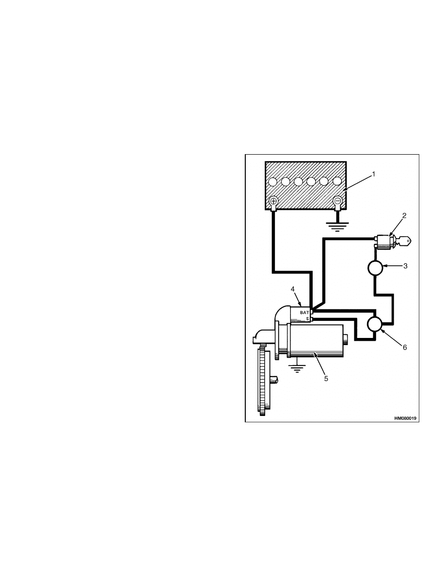
The positive battery cable is connected to the "BAT"
terminal on the starter solenoid. See Figure 1, Fig-
ure 2, and Figure 3. Battery voltage is not applied
to the starter until the ignition switch, the solenoid
switch (diesel units only), and the transmission neu-
tral switch close. The solenoid moves the linkage and
the drive clutch to engage the starter pinion with the
ring gear. At the end of its stroke, the plunger of the
solenoid closes the main solenoid contacts. The cur-
rent then flows to the starter windings. The starter
pinion turns the flywheel ring gear.
The starter is a linkage type with a drive clutch
mechanism. The solenoid is fastened to the starter.
The pinion is part of the drive clutch. The drive
clutch is moved on the armature shaft by the linkage
connected to the solenoid plunger. When the engine
starts, the pinion is still engaged with the ring gear.
The pinion turns freely when driven by the ring gear.
When the key is released, the pinion moves away
from the ring gear and the starter circuit opens.
When energized, the starter solenoid moves the link-
age, closes the contacts, and energizes the starter.
The solenoid has two windings. When energized, one
winding pulls the solenoid plunger to close the con-
tacts. The other winding holds the plunger in that
position. The current for the winding that pulls must
flow through the starter brushes to a ground. The
ground for the winding that holds the plunger in po-
sition is the solenoid frame. When the key switch
is closed, the current flows through both windings.
When the plunger moves the linkage, the contacts
close, which causes the winding that pulls to have
a short circuit. That winding is deenergized, but
the current continues to flow through the winding
that holds the plunger. The winding that holds the
plunger is deenergized when the key switch is re-
leased.
The solenoid switch is a relay that is used in the
diesel starter circuit. The solenoid for the starter of
the diesel engine uses more current than does the so-
lenoid for the starter of the gasoline engine. The so-
lenoid switch is actuated by turning the key switch to
the START position. The solenoid switch closes the
contacts that energize the solenoid of the starter.
1. BATTERY
2. IGNITION SWITCH
3. NEUTRAL START SWITCH (CAN CONSIST OF
SEVERAL RELAYS)
4. STARTER SOLENOID
5. STARTER
6. SOLENOID SWITCH (NOT ON ALL UNITS)
Figure 1. Starting Circuit
1
Description and Operation
2200 SRM 106
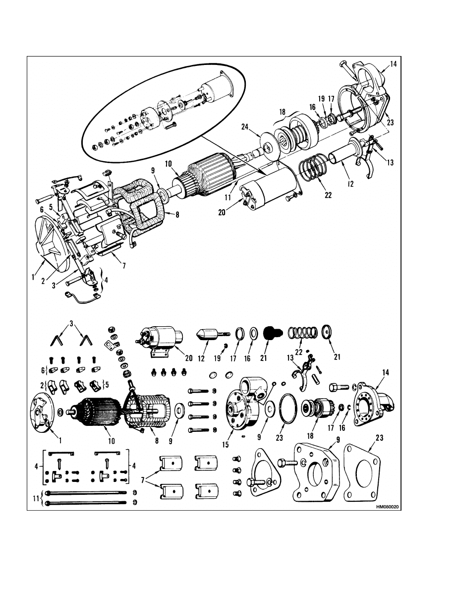
Figure 2. Starter
2
2200 SRM 106
Starter Repair
Legend for Figure 2
1. END FRAME
2. GROUND BRUSH HOLDER
3. BRUSH SPRING
4. BRUSH SUPPORT
5. INSULATED BRUSH HOLDER
6. BRUSH
7. POLE SHOE
8. FIELD COIL
9. SPACER
10. ARMATURE
11. THROUGH BOLT
12. SOLENOID PLUNGER
13. LINKAGE
14. DRIVE HOUSING
15. LEVER HOUSING
16. RETAINER
17. THRUST COLLAR
18. DRIVE CLUTCH
19. SNAP RING
20. SOLENOID
21. COVER
22. SPRING
23. GASKET
24. CENTER BEARING PLATE
AND SEAL
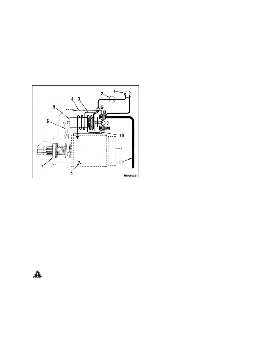
1. KEY SWITCH
2. NEUTRAL START
SWITCH
3. HOLD WINDING
4. SOLENOID
5. PLUNGER
6. DRIVE LINKAGE
7. DRIVE CLUTCH
8. STARTER
9. CONTACTS
10. PULL WINDING
11. TO BATTERY
Figure 3. Solenoid Windings
Starter Repair
REMOVE
NOTE: If the starter does not operate correctly, refer
to General Checks and Adjustments before beginning
any repair procedures.
WARNING
Always disconnect the battery ground cable be-
fore making repairs to prevent possible dam-
age and injury. Install a tag on the battery ter-
minal so that no one connects the cable on the
terminal.
1. Install labels on the starter wires and cables for
correct connection during installation. Discon-
nect the wires and the cables to the starter.
2. Remove the capscrews that hold the starter to
the flywheel housing.
3. If used, remove the spacers and the gaskets.
4. Remove the starter from the lift truck.
DISASSEMBLE
1. Remove the screw and lock washer connecting
the field coil strap to the "M" terminal of the so-
lenoid. See Figure 2 and Figure 4.
3
Starter Repair
2200 SRM 106
2. Remove the two screws that hold the solenoid to
the drive end housing. Turn the solenoid 1/4 turn
and remove it from the starter.
3. Remove the two bolts that hold the commutator
end frame and the field frame to the drive hous-
ing. Make alignment marks on the end frame
and on the field frame for easy assembly. Pull the
end frame from the field frame. On some models
it is necessary to pull the brushes from the hold-
ers. Remove the field frame.
4. If used, remove the four screws holding the cen-
ter bearing plate to the drive end housing.
5. Remove the armature from the drive end hous-
ing. Tilt the armature to disengage the linkage
from the drive clutch. On some models it is nec-
essary to remove the linkage before removing the
armature.
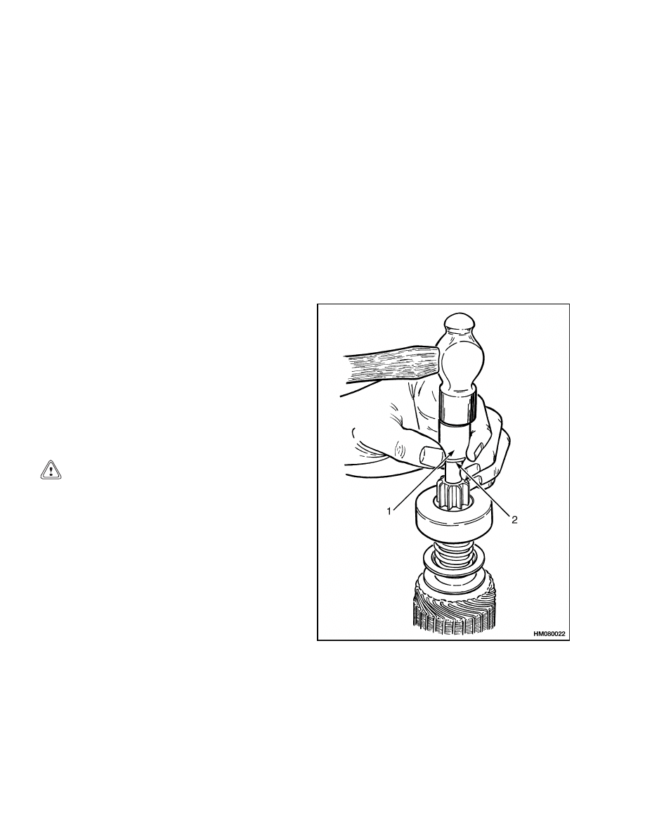
6. Remove the thrust collar from the armature
shaft. Put a metal tube with a 13 mm (0.5 in.)
inside diameter over the end of the shaft. See
Figure 4. Hit the tube to move the retainer.
Remove the snap ring. Remove the drive clutch.
7. Remove the center bearing plate. Remove the
seal from the plate.
CLEAN
CAUTION
Never use solvent on the drive clutch, arma-
ture, or field windings. Use a cloth to clean
these parts.
Use solvent to clean all parts of the starter, except
the windings and the drive clutch. Dry the parts with
compressed air.
ASSEMBLE
1. Install a new seal in the center bearing plate. See
2. Lubricate the armature shaft and the bushings
with a silicone lubricant.
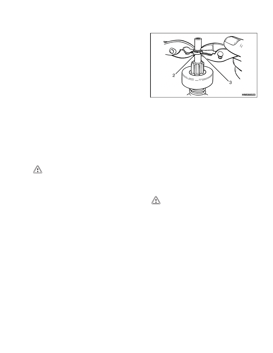
3. Put the center bearing plate, drive clutch, re-
tainer, snap ring, and thrust washer on the
armature shaft. Install the snap ring, thrust
washer, and retainer as shown in Figure 5.
4. Install the shaft assembly in the drive end hous-
ing. Make sure the linkage is engaged in the
drive clutch. Install and tighten the four screws
for the bearing plate.
5. Install the field frame over the armature. Re-
tract the brush springs and slide the brushes on
the commutator.
6. Align the marks and install the thrust washer
and the commutator end frame.
Install and
tighten the through bolts.
7. Make sure the solenoid cover is not damaged. In-
stall the plunger spring and the solenoid. Install
and tighten the solenoid mount screws. Connect
the field coil strap to the "M" terminal with the
screw and lock washer.
1. METAL TUBE, 13 mm (0.5 in.) INSIDE DIAMETER
2. RETAINER
Figure 4. Retainer Removal
4
2200 SRM 106
General Checks and Adjustments
INSTALL
1. Make sure the surfaces of the flywheel housing,
the spacer, and the starter are clean and smooth.
Install the gaskets or use a sealant (Hyster part
number 264159) that forms a gasket between
metal parts.
2. Install the capscrews and washers as necessary.
Tighten the capscrews.
3. Connect the wires and the cables to the starter
according to the labels made during removal.
4. Connect the ground cable to the battery.
1. THRUST COLLAR
2. RETAINER
3. SNAP RING
Figure 5. Retainer Installation
General Checks and Adjustments
1. Before removing the starter, see Figure 6 and
Figure 7. Make the following checks:
a. Check the voltage of the battery.
CAUTION
Do not operate the starter for more than 30 sec-
onds. Be sure to wait at least two minutes be-
tween checks.
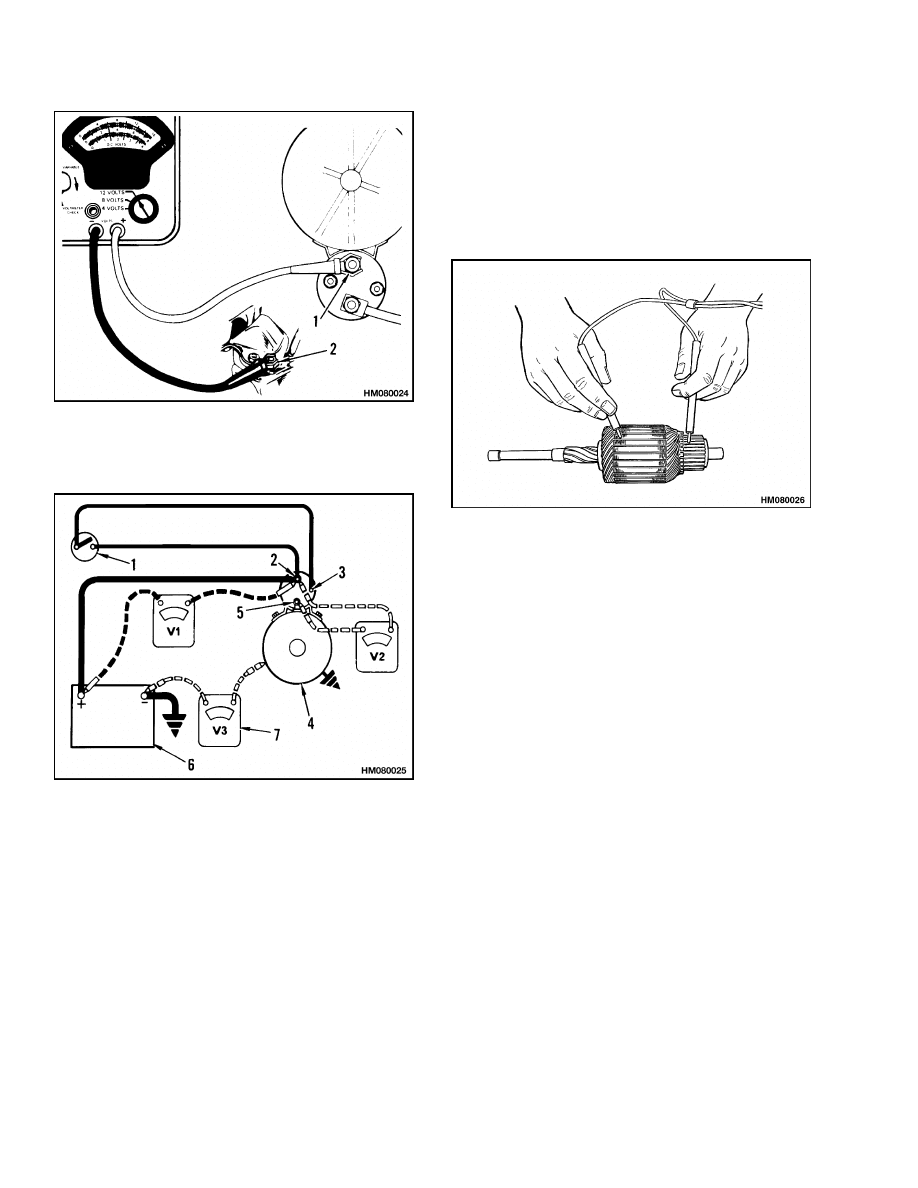
b. Check the voltage at the motor terminal of
the solenoid while the key switch is in the
"START" position. See Figure 6. The voltage
must be more than 9 volts for a 12-volt sys-
tem or more than 18 volts for a 24-volt sys-
tem.
c. Inspect all the connections to the battery,
starter solenoid, key switch, and neutral
start switch. Clean and tighten, if necessary.
d. Check the resistance of the connections with
a voltmeter. See Figure 7. Each connection
must not have more than a 0.5 volt loss for
a 12-volt system or 1.0 loss for a 24-volt sys-
tem.
e. Check the voltage at the "S" terminal of the
solenoid. It must be more than 7 volts for
a 12-volt system or more than 14 volts for a
24-volt system.
2. After removing the starter, but before disassem-
bly, make the following checks:
a. Check the ring gear (on the flywheel) for
damage.
CAUTION
The pinion will move toward the drive end
housing when turned in the locked direction.
Do not turn it too far or it will lock in the
extended position.
b. Check the pinion gear (on the drive clutch)
for damage. The pinion must turn in one
direction and lock in the other. Replace the
complete assembly if any part has damage.
c. Check the clearance of the armature bush-
ings.
d. Check for cracks in the drive end housing.
5
General Checks and Adjustments
2200 SRM 106
1. MOTOR TERMINAL
2. GROUND ON
ENGINE
Figure 6. Starter Voltage Test
1. KEY SWITCH
2. "BAT" TERMINAL
3. "S" TERMINAL
4. STARTER
5. "M" TERMINAL
6. BATTERY
7. VOLTMETER
Figure 7. Resistance Test
3. When the starter is disassembled, make the fol-
lowing checks:
a. Check that the seals are good on units that
use an oil clutch or a powershift transmis-
sion.
b. Check for wear in the linkage.
c. Test for a ground in the armature windings.
See Figure 8. Touch one wire of an ohmmeter
to the shaft and the other to each commuta-
tor bar. The armature has a short-circuit to
ground if the ohmmeter indicates a complete
circuit.
Figure 8. Armature Ground Tests
d. Test for open circuits in the armature. Put
one wire of an ohmmeter on one commuta-
tor bar and the other on the bar 180 de-
grees opposite. The ohmmeter must indicate
a complete circuit. Commutator bars that
are burned indicate an open circuit.
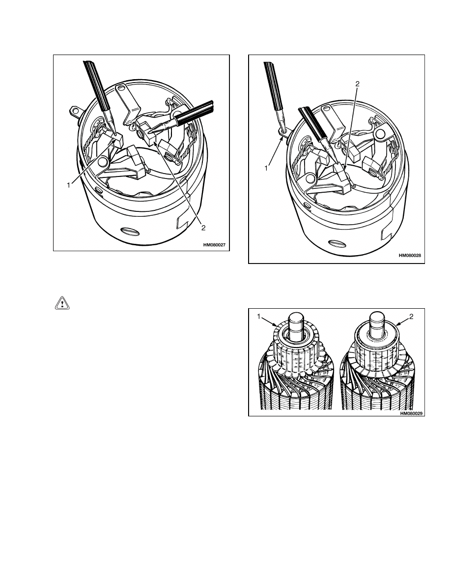
e. Test for a ground in the field coil circuit. See
Figure 9. Touch one wire of an ohmmeter
to the field frame and the other to the field
coil brushes. On some models it is neces-
sary to disconnect the field ground strap. The
field coils have a short-circuit to ground if the
ohmmeter indicates a complete circuit.
f. Test for an open circuit in the field coils. See
Figure 10. Connect the wires of an ohmmeter
to the ends of the field coils. The ohmmeter
must indicate a complete circuit.
g. Check that the brush springs have enough
tension.
h. Check the brushes for wear. The brushes
must be at least one half the length of new
ones.
6
2200 SRM 106
General Checks and Adjustments
1. INSULATED
BRUSH
2. GROUND BRUSH
Figure 9. Field Coil Ground Test
CAUTION
Remove only enough metal to clean the surface
on the commutators with the plastic insulation.
See Figure 11. Do not cut the insulation be-
tween the bars on the commutator. The plastic
material is necessary to support the bars. The
plastic material is softer than the bars and will
wear at the same rate.
i. If the commutator is rough or is burned, it
must be repaired with a lathe.
j. Check for bad solder connections at the com-
mutator bars. Solder the connections that
have damage.
1. FIELD COIL STRAP
2. GROUND BRUSH
Figure 10. Field Coil Open Circuit Test
1. COMMUTATOR WITH MICA INSULATION
2. COMMUTATOR WITH PLASTIC INSULATION
(DO NOT CUT INSULATION)
Figure 11. Two Types of Insulation
7

Troubleshooting
2200 SRM 106
Troubleshooting
PROBLEM
POSSIBLE CAUSE
PROCEDURE OR ACTION
The starter will not turn; no
noise at the solenoid.
Battery is discharged or has damage.
Recharge or replace battery.
A fuse is burned out.
Replace fuse.
A wire in the control circuit is discon-
nected.
Connect wire.
The key switch has damage.
Install new parts.
The neutral start switch has dam-
age.
Install new parts.
The cable connections are bad.
Install new parts.
The solenoid has damage.
Replace solenoid.
The starter brushes are worn or
dirty.
Replace brushes.
The solenoid switch has damage.
Replace switch.
The starter will not turn; the
solenoid makes noise.
The battery is discharged or has
damage.
Recharge or replace battery.
The starter brushes are worn or
dirty.
Replace brushes.
The contacts in the solenoid are
worn.
Install new parts.
The armature circuit has damage.
Repair or install new parts.
The cable connections have too much
resistance.
Clean or install new parts.
The starter will not turn.
The ammeter indicates a
large current draw.
The control circuit has a short cir-
cuit.
Check wiring for damage and repair.
The pinion is not engaging the ring
gear.
Check the clutch on the starter for
damage and repair.
The solenoid has damage.
Replace solenoid.
8

2200 SRM 106
Troubleshooting
PROBLEM
POSSIBLE CAUSE
PROCEDURE OR ACTION
The cables get too hot.
The battery is discharged or has
damage.
Recharge or replace the battery.
The pinion is not disengaging from
the ring gear.
Check the clutch on the starter for
damage and repair.
The armature shaft is bent.
Repair or replace armature.
The cable has a short circuit.
Repair or replace cable.
The bushings are worn or damaged.
Replace bushings.
The engine has damage.
Repair or install new parts.
The starter turns too slowly.
The battery is discharged or has
damage.
Recharge or replace battery.
The cable connections have too much
resistance.
Repair or install new parts.
The starter brushes are worn or
dirty.
Clean or replace brushes.
The armature circuit has damage.
Repair or replace armature.
The field circuit has damage.
The starter brushes are worn or
dirty.
Clean or replace brushes.
The ring gear has damage.
Install new parts.
The engine has damage.
Repair or install new parts.
The ignition timing is not correct.
Recalibrate the ignition timing.
The starter turns, but the
engine will not turn.
The drive clutch has damage.
Install new parts.
The pinion is not disengaging from
the ring gear.
Check the clutch on the starter for
damage and repair.
The ring gear has damage.
Install new parts.
9

Troubleshooting
2200 SRM 106
PROBLEM
POSSIBLE CAUSE
PROCEDURE OR ACTION
The starter makes too much
noise.
The solenoid has damage.
Replace solenoid.
The ring gear has damage.
Install new parts.
The drive clutch has damage.
Install new parts.
The battery is discharged or has
damage.
Recharge or replace battery.
The starter brushes are worn or
dirty.
Replace brushes.
10

TECHNICAL PUBLICATIONS
2200 SRM 106
2/01 (4/93) (4/80)(12/78) Printed in United Kingdom
Document Outline
Wyszukiwarka
Podobne podstrony:
897509 2200SRM0524 (02 2001) UK EN
897594 2200SRM0550 (02 2001) UK EN
1538373 2200SRM1065 (02 2004) UK EN
1466193 2200SRM0755 (11 2001) UK EN
897553 1900SRM0539 (02 2001) UK EN
897590 8000SRM0546 (02 2001) UK EN
1452929 2200SRM0679 (11 2003) UK EN
1474823 2200SRM0781 (11 2001) US EN
897393 1800SRM0452 (02 2004) UK EN
1566279 8000SRM1155 (02 2005) UK EN
897070 2200SRM0288 (01 1994) UK EN
więcej podobnych podstron