STARTER
H3.50-5.50XM (H70-120XM) [K005];
S3.50-5.50XM (H70-120XM) [E004]
PART NO. 1466193
2200 SRM 755

SAFETY PRECAUTIONS
MAINTENANCE AND REPAIR
• When lifting parts or assemblies, make sure all slings, chains, or cables are correctly
fastened, and that the load being lifted is balanced. Make sure the crane, cables, and
chains have the capacity to support the weight of the load.
• Do not lift heavy parts by hand, use a lifting mechanism.
• Wear safety glasses.
• DISCONNECT THE BATTERY CONNECTOR before doing any maintenance or repair
on electric lift trucks.
• Disconnect the battery ground cable on internal combustion lift trucks.
• Always use correct blocks to prevent the unit from rolling or falling. See HOW TO PUT
THE LIFT TRUCK ON BLOCKS in the Operating Manual or the Periodic Mainte-
nance section.
• Keep the unit clean and the working area clean and orderly.
• Use the correct tools for the job.
• Keep the tools clean and in good condition.
• Always use HYSTER APPROVED parts when making repairs. Replacement parts
must meet or exceed the specifications of the original equipment manufacturer.
• Make sure all nuts, bolts, snap rings, and other fastening devices are removed before
using force to remove parts.
• Always fasten a DO NOT OPERATE tag to the controls of the unit when making repairs,
or if the unit needs repairs.
• Be sure to follow the WARNING and CAUTION notes in the instructions.
• Gasoline, Liquid Petroleum Gas (LPG), Compressed Natural Gas (CNG), and Diesel fuel
are flammable. Be sure to follow the necessary safety precautions when handling these
fuels and when working on these fuel systems.
• Batteries generate flammable gas when they are being charged. Keep fire and sparks
away from the area. Make sure the area is well ventilated.
NOTE:
The following symbols and words indicate safety information in this
manual:
WARNING
Indicates a condition that can cause immediate death or injury!
CAUTION
Indicates a condition that can cause property damage!

Starter
Table of Contents
TABLE OF CONTENTS
General ...............................................................................................................................................................
Description .........................................................................................................................................................
Yoke Assembly ...............................................................................................................................................
Armature Assembly.......................................................................................................................................
Clutch Assembly ............................................................................................................................................
Magnetic Switch Assembly ...........................................................................................................................
Operation............................................................................................................................................................
Starter Repair ....................................................................................................................................................
Remove ...........................................................................................................................................................
Disassemble ...................................................................................................................................................
Clean ..............................................................................................................................................................
Assemble ........................................................................................................................................................
Install .............................................................................................................................................................
General Checks and Adjustments.....................................................................................................................
Armature Tests...................................................................................................................................................
Armature Short Circuit Test .........................................................................................................................
Armature Winding Ground Test ...................................................................................................................
Commutator Run-Out Test ...........................................................................................................................
Yoke Test.............................................................................................................................................................
Brush and Brush Holder Check ........................................................................................................................
Brush Holder Insulation Test .......................................................................................................................
Clutch Test .....................................................................................................................................................
Magnetic Switch Test.........................................................................................................................................
Pull-In Test.....................................................................................................................................................
Hold-In Test ...................................................................................................................................................
Return Test ....................................................................................................................................................
Performance Tests..............................................................................................................................................
No-Load Test ..................................................................................................................................................
Troubleshooting..................................................................................................................................................
This section is for the following models:
H3.50-5.50XM (H70-120XM) [K005];
S3.50-5.50XM (H70-120XM) [E004]
©2002 HYSTER COMPANY
i

"THE
QUALITY
KEEPERS"
HYSTER
APPROVED
PARTS
2200 SRM 755
Description
General
This section has a description and the service procedures for the starter and subassemblies.
Description
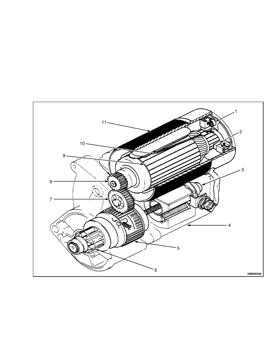
The reduction starter (Figure 1) is a positive shift
type starter assembly consisting of the yoke assem-
bly, the armature assembly, the clutch assembly, the
magnetic switch assembly, and the reduction gears.
In the reduction type starter, the armature rotation
speed transferred to the pinion is reduced by one-
third to one-fourth by the reduction gears. The ro-
tation is transferred to the pinion through the clutch
mechanism.
1. BRUSH SPRING
2. BRUSH
3. PLUNGER
4. MAGNETIC SWITCH
5. CLUTCH
6. PINION
7. IDLE GEAR
8. DRIVE GEAR
9. ARMATURE
10. FIELD COIL
11. YOKE
Figure 1. Reduction Starter
1
Operation
2200 SRM 755
YOKE ASSEMBLY
The yoke assembly consists of the yoke, pole shoes,
field windings, and brushes.
The field windings are connected in series with the
armature windings through brushes and commuta-
tors. Unlike conventional starters, the two positive
brushes are welded to the field windings.
ARMATURE ASSEMBLY
The armature assembly consists of the windings,
commutator, felt wick oiler, and shaft. The armature
is supported by two high-speed ball bearings.
The armature windings are mounted in a core and
reinsulated from the core and each other. The wind-
ings are connected at the commutator segments.
CLUTCH ASSEMBLY
The clutch assembly consists of the pinion, pinion
shaft, and clutch. The clutch is supported by two
high-speed ball bearings. Screw splines are ma-
chined on the rear of the pinion shaft.
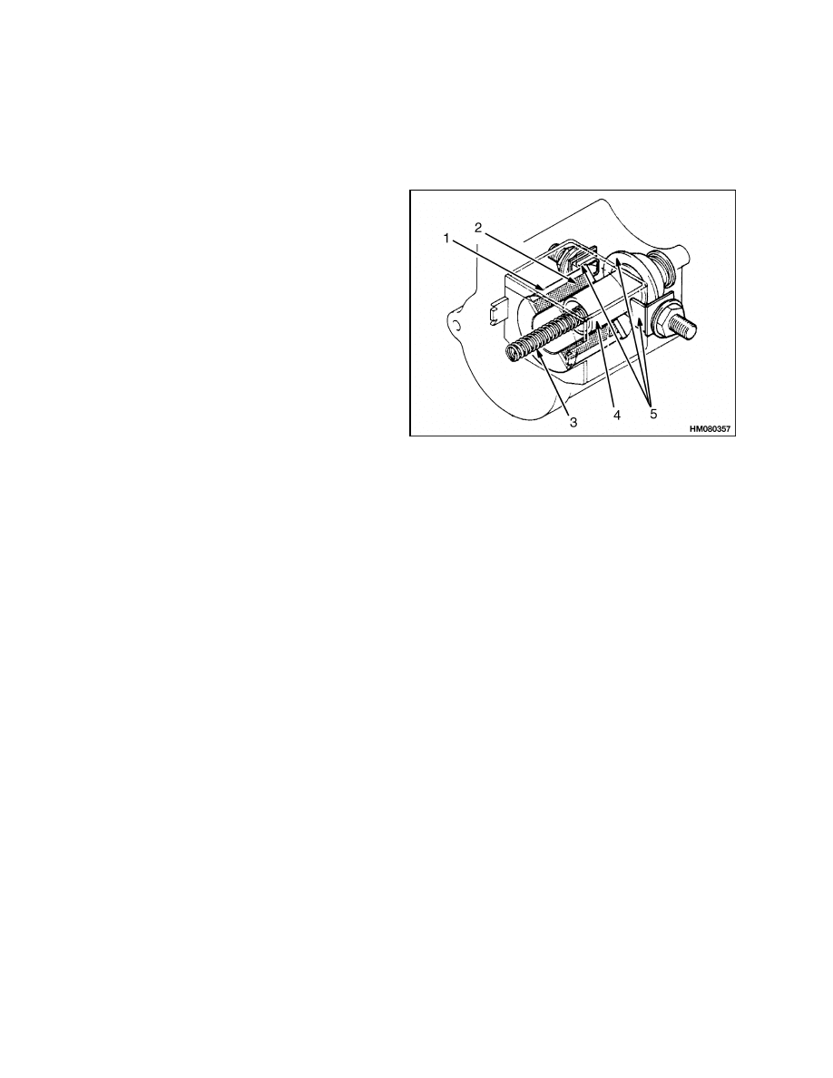
MAGNETIC SWITCH ASSEMBLY
The magnetic switch assembly (Figure 2) consists
of the main contacts, plunger, plunger shaft, pull-in
coil, hold-in coil, and return spring.
1. PULL-IN COIL
2. HOLD-IN COIL
3. RETURN SPRING
4. PLUNGER
5. MAIN CONTACTS
Figure 2. Magnetic Switch Assembly
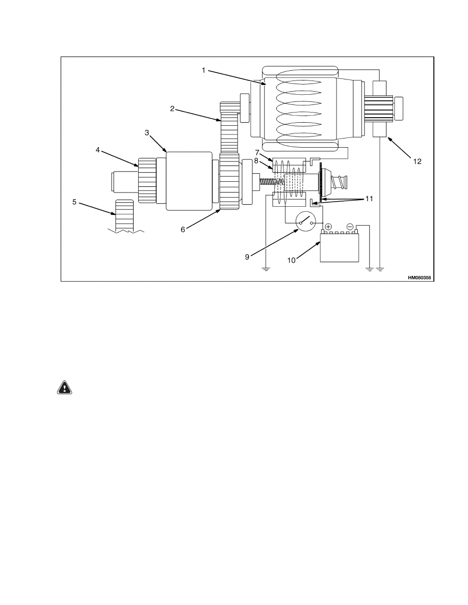
Operation
The positive battery cable is connected to the large
terminal on the magnetic switch assembly. See Fig-
ure 3. Battery voltage is not applied to the starter
until the ignition switch closes. The magnetic switch
moves the linkage and the drive clutch to engage the
starter pinion with the ring gear. At the end of its
stroke, the plunger of the magnetic switch closes the
main switch contacts. The current then flows to the
armature windings. The starter pinion turns the fly-
wheel ring gear.
When the starter switch is closed, the battery cur-
rent flows through the pull-in coil and the hold-in
coil. This causes the plunger to be pulled in to make
contact with the main contacts. Battery current then
flows through the main contacts to the armature
windings and the starter begins to crank the engine.
At the same time, the hold-in coil maintains the
plunger in the pull-in position.
When the starting switch is opened and the magnetic
switch contacts are closed, the current flows through
both the pull-in coil and the hold-in coil in the same
direction. The magnetic force in the hold-in coil is
reduced, allowing the plunger to be pulled back to its
original position by the force of the return spring and
by opening the magnetic switch main contacts.
2
2200 SRM 755
Starter Repair
1. ARMATURE
2. IDLE GEAR
3. CLUTCH
4. PINION
5. RING GEAR
6. CLUTCH GEAR
7. HOLDING COIL
8. PULL-IN COIL
9. STARTER SWITCH
10. BATTERY
11. MAIN CONTACTS
12. BRUSHES
Figure 3. Electrical Operation
Starter Repair
REMOVE
WARNING
Always disconnect the battery ground cable be-
fore making repairs to prevent possible dam-
age and injury. Install a tag on the battery ter-
minal so no one connects the cable on the ter-
minal.
NOTE:
If the starter does not operate correctly, refer
to General Checks and Adjustments before beginning
any repair procedures.
1. Install labels on starter wires and cables for cor-
rect connection during installation. Disconnect
wires and cables to starter.
2. Remove two bolts and washers that hold starter
to flywheel housing.
3. Remove starter from lift truck.
3
Starter Repair
2200 SRM 755
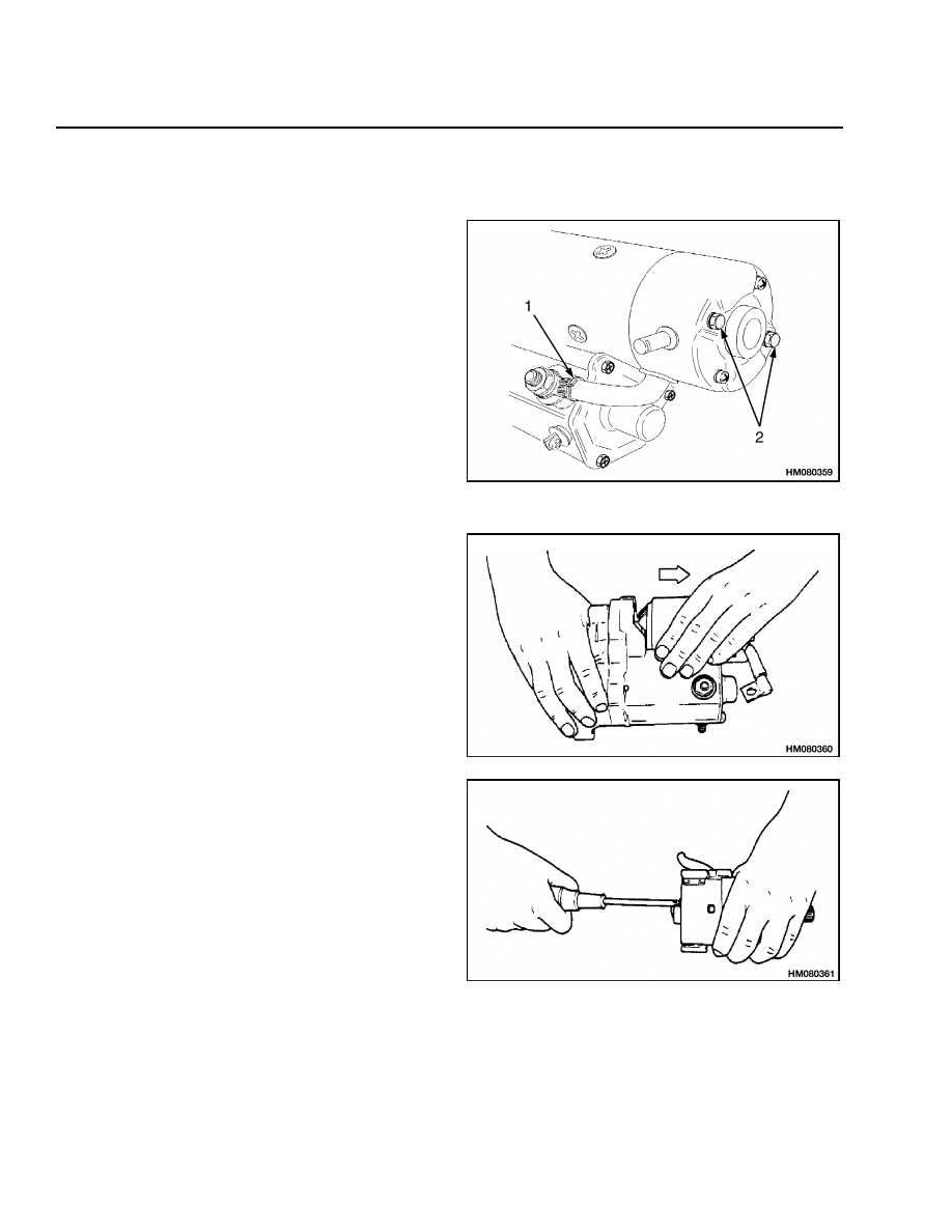
DISASSEMBLE
Disassemble the starter as follows:
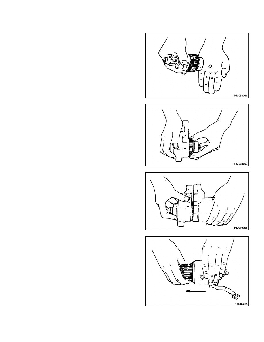
STEP 1.
Disconnect lead wire from magnetic switch and re-
move two through-bolts from rear end frame.
1. LEAD WIRE
2. THROUGH-BOLTS
STEP 2.
Remove yoke.
STEP 3.
Remove screws from end frame.
4
2200 SRM 755
Starter Repair
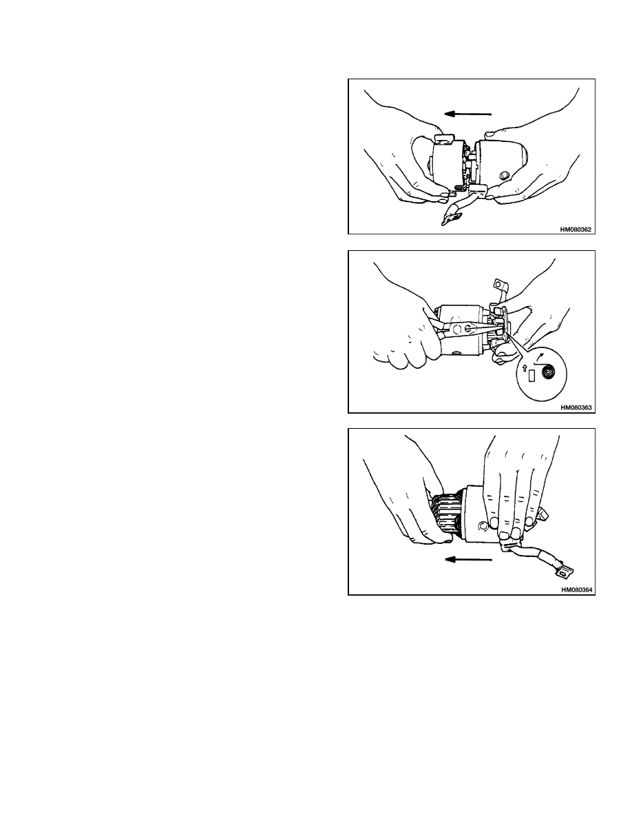
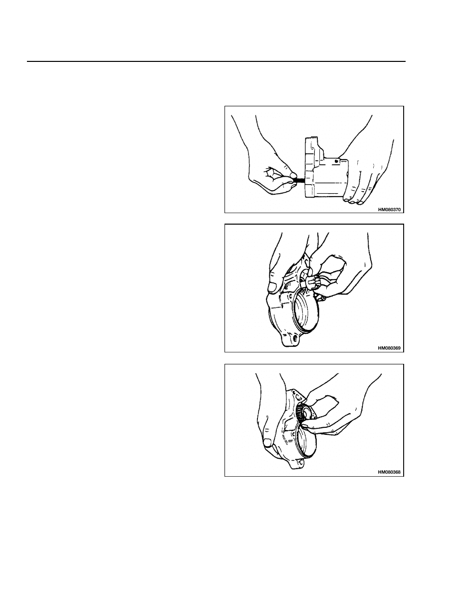
STEP 4.
Remove end frame from yoke.
STEP 5.
Remove brushes from brush holder and remove brush
holder.
STEP 6.
Remove armature from yoke.
5
Starter Repair
2200 SRM 755
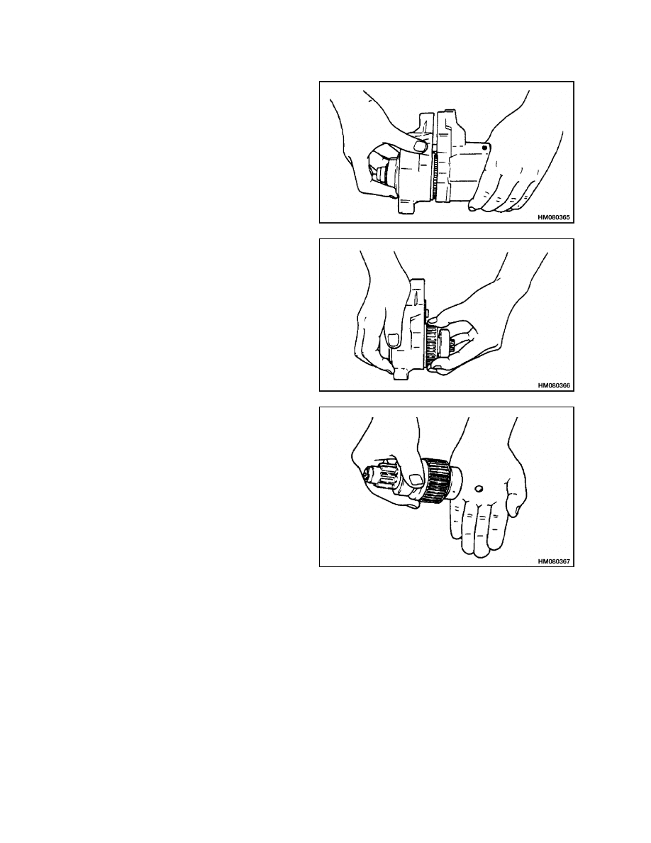
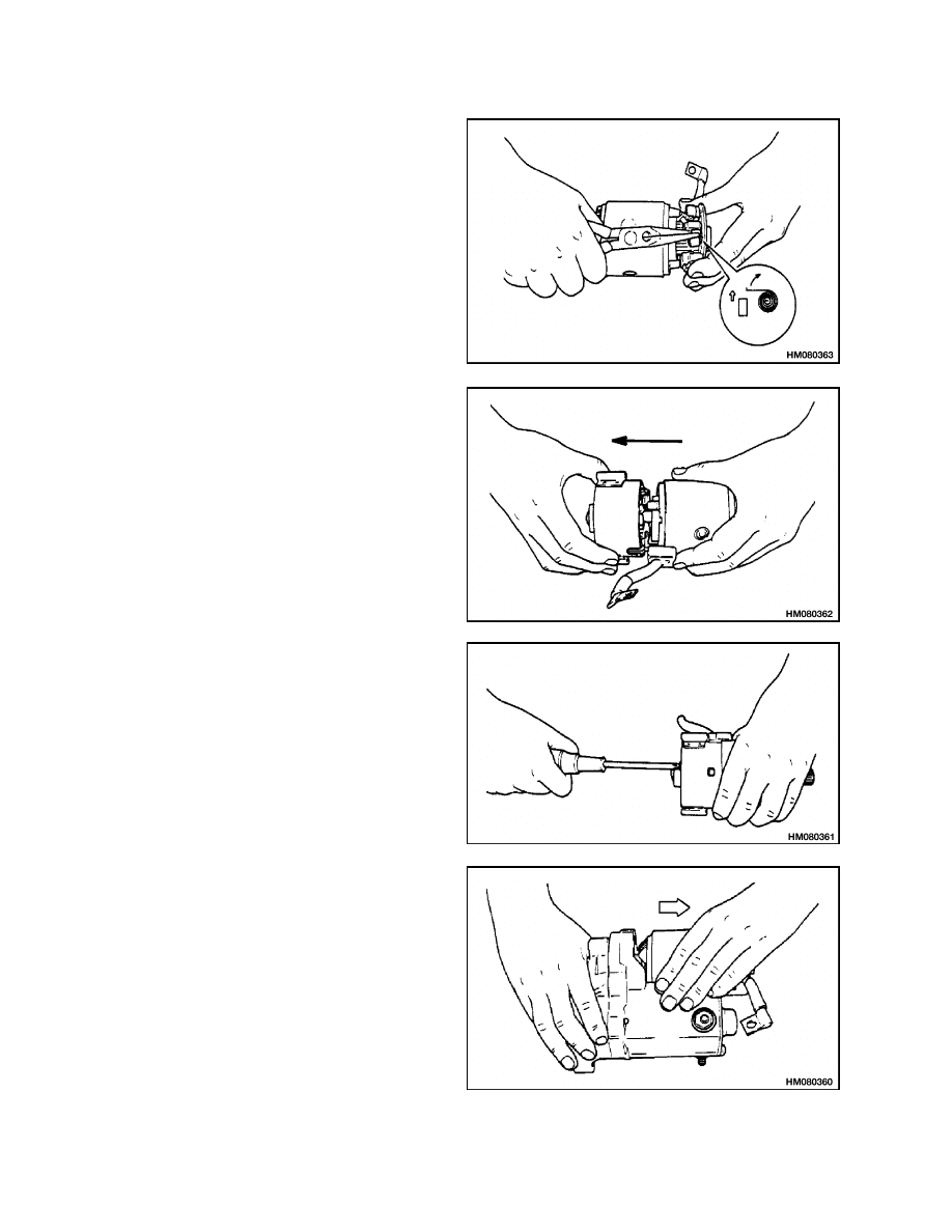
STEP 7.
Remove three screws from drive end frame and sep-
arate it from magnetic switch.
STEP 8.
Remove clutch from drive end frame.
STEP 9.
Remove steel ball from clutch.
6
2200 SRM 755
Starter Repair
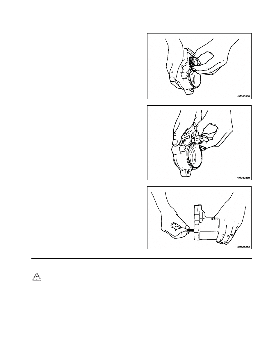
STEP 10.
Remove pinion from drive end frame.
STEP 11.
Remove retainer and rollers from end frame.
STEP 12.
Remove return spring.
CLEAN
CAUTION
Never use solvent on the drive clutch, arma-
ture, or field windings. Use a cloth to clean
these parts.
Use solvent to clean all parts of the starter, except
windings and drive clutch. Dry parts with com-
pressed air.
7
Starter Repair
2200 SRM 755
ASSEMBLE
Assemble the starter as follows:
STEP 1.
Install return spring.
STEP 2.
Install pinion into drive end frame.
STEP 3.
Install retainer and rollers into drive end frame.
8
2200 SRM 755
Starter Repair
STEP 4.
Install steel ball into clutch.
STEP 5.
Install clutch into drive end frame.
STEP 6.
Connect drive end frame to magnetic switch and in-
stall three screws.
STEP 7.
Install armature into yoke.
9
Starter Repair
2200 SRM 755
STEP 8.
Install brushes and install brush holder into yoke.
STEP 9.
Install end frame into yoke.
STEP 10.
Install two screws into end frame.
STEP 11.
Install yoke onto magnetic switch.
10
2200 SRM 755
General Checks and Adjustments
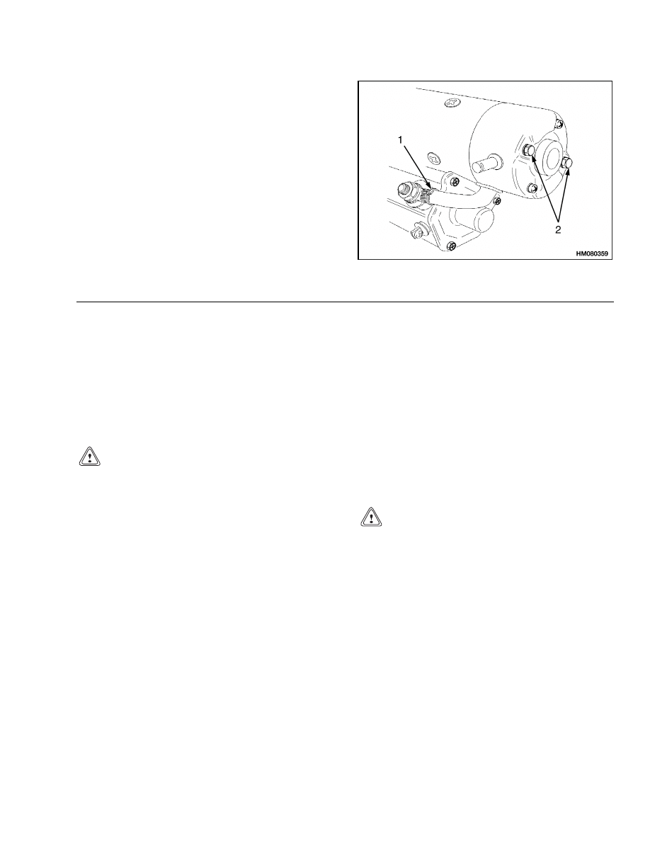
STEP 12.
Install two through-bolts into rear end frame and
connect lead wire.
1. LEAD WIRE
2. THROUGH-BOLTS
INSTALL
1. Make sure surfaces of flywheel housing and
starter are clean and smooth.
2. Install capscrews and washers as necessary.
Tighten capscrews.
3. Connect wires and cables to starter according to
labels made during removal.
4. Connect ground cable to battery.
General Checks and Adjustments
CAUTION
Do not operate the starter for more than 30 sec-
onds. Be sure to wait at least 2 minutes be-
tween checks.
Before removing the starter, make the following
checks:
1. Check battery voltage using a battery breakdown
tester. Make sure battery tests good.
2. Inspect all connections to battery, starter mag-
netic switch, key switch, and neutral start
switch. Clean and tighten, if necessary.
After removing the starter, but before disassembly,
make the following checks:
1. Check ring gear (on flywheel) for damage.
2. Check pinion gear (on drive clutch) for damage.
The pinion must turn in one direction and lock in
the other. Replace complete assembly if any part
has damage.
CAUTION
The pinion will move toward the drive end
housing when turned in the locked direction.
Do not turn it too far or it will lock in the
extended position.
3. Check for cracks in drive end housing.
When the starter is disassembled, make the follow-
ing checks: Armature Tests, Yoke Test, Brush and
Brush Holder Check, and Magnetic Switch Test.
11
Armature Tests
2200 SRM 755
Armature Tests
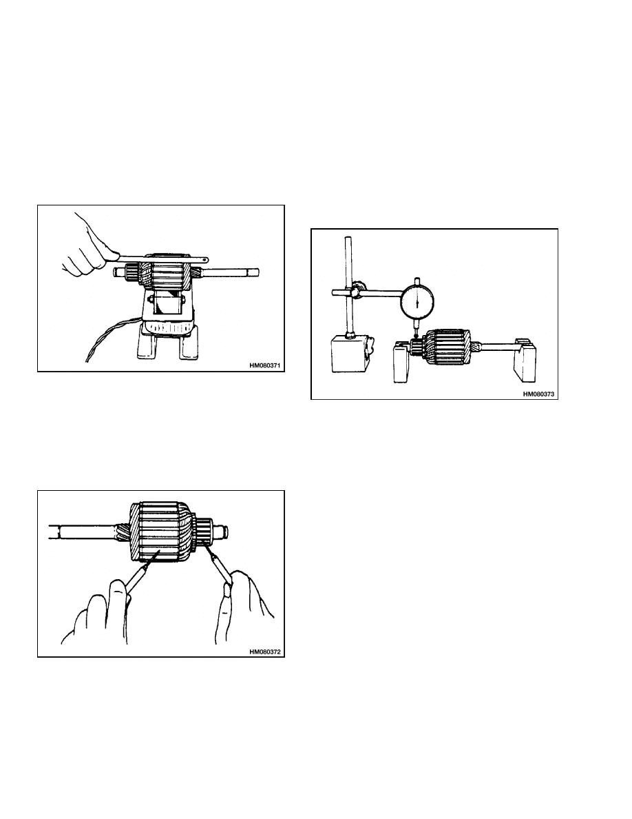
ARMATURE SHORT CIRCUIT TEST
Using a growler tester, place the armature on the
tester and hold a hacksaw blade against the coil
while slowly rotating the armature. See Figure 4. If
the armature has a short circuit, the blade vibrates
and is attracted to the core. Replace armature if it
has a short circuit.
Figure 4. Armature Short Circuit Test
ARMATURE WINDING GROUND TEST
Touch one wire of an ohmmeter to the armature shaft
and the other to each commutator bar as shown in
Figure 5. The armature has a short circuit to ground
if the ohmmeter indicates a complete circuit.
Figure 5. Armature Ground Test
COMMUTATOR RUN-OUT TEST
First check the armature commutator surface for
burn spots. This usually indicates an open circuit.
If the commutator has visible burn spots, replace
armature.
Check commutator run-out as shown in Figure 6.
Maximum allowable run-out is 0.4 mm. If run-out
exceeds the limit, replace armature.
Figure 6. Commutator Run-Out Test
12
2200 SRM 755
Brush and Brush Holder Check
Yoke Test
1. Touch one wire of an ohmmeter to the field frame
and the other to the field coil brushes as shown
in Figure 7. If the meter indicates a complete cir-
cuit, the field coils have a short circuit to ground.
Replace yoke.
2. Connect ohmmeter to ends of field coils. The me-
ter must indicate a complete circuit. If it does not
show a complete circuit, replace yoke.
3. Check that brush springs have enough tension.
4. Check brushes for wear. The brushes must be at
least one-third the length of new ones.
5. Check for bad solder connections at commutator
bars. Solder connections that have damage.
Figure 7. Yoke Winding Continuity Test
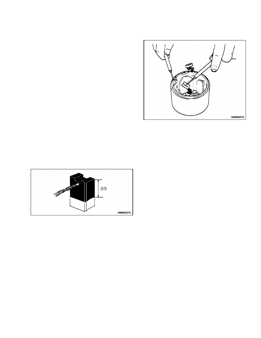
Brush and Brush Holder Check
1. Check brush for excessive wear. Replace brush
when it has reached two-thirds of its original
size. See Figure 8.
Figure 8. Brush Measurement
2. Check brush spring for rust or damage and re-
place if necessary.
BRUSH HOLDER INSULATION TEST
Using an ohmmeter, touch one probe to the positive
(+) brush holder and the other to the brush holder
plate. The ohmmeter should indicate an open circuit.
If the ohmmeter shows continuity, replace or repair
brush holder or plate.
CLUTCH TEST
Inspect pinion and make sure it can be rotated freely
in the direction of the starter rotation and that it is
locked in the opposite direction.
13
Magnetic Switch Test
2200 SRM 755
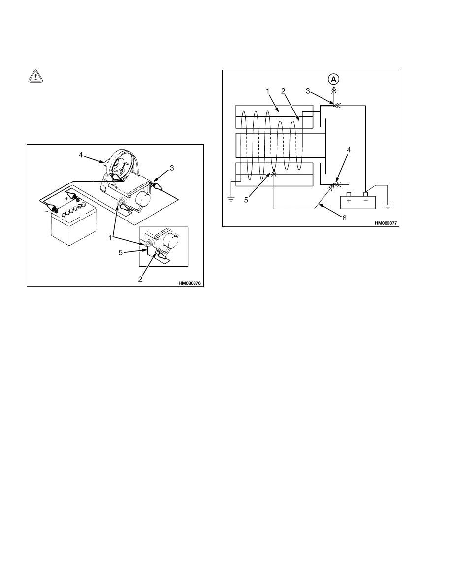
Magnetic Switch Test
CAUTION
To prevent the magnetic switch winding from
burning out, each test should be performed for
no more than 3 to 5 seconds.
The following tests should be performed without the
armature installed. See Figure 9.
1. MAIN TERMINAL
2. STARTER
TERMINAL
3. COIL TERMINAL
4. SWITCH CASE
5. JUMPER
Figure 9. Magnetic Switch Test
PULL-IN TEST
Connect negative leads from battery to case and to
coil terminal of switch as shown in Figure 9.
Connect a jumper between main terminal and starter
terminal. A schematic of the connections is shown in
Figure 10.
A. TO ARMATURE
1. HOLDING COIL
2. PULL-IN COIL
3. COIL TERMINAL
4. MAIN TERMINAL
5. STARTER
TERMINAL
6. JUMPER
Figure 10. Magnetic Switch Test Schematic
Connect positive terminal to coil terminal of switch.
The pinion should extend when the positive terminal
is connected.
HOLD-IN TEST
Remove connection from coil terminal and make sure
the pinion remains in the extended position.
RETURN TEST
Remove connection from starter terminal and make
sure the pinion returns to its original position.
14
2200 SRM 755
Troubleshooting
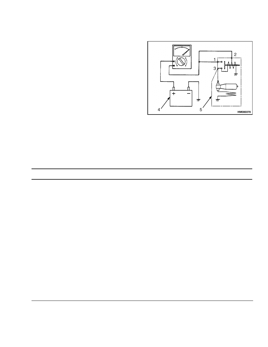
Performance Tests
Perform the following tests after reassembling the
starter.
NO-LOAD TEST
1. Clamp starter securely in a vise and connect bat-
tery and ammeter as shown in Figure 11.
2. Connect negative lead to starter body.
3. Make sure pinion extends and starter shows
smooth and steady rotation.
1. MAIN TERMINAL
2. STARTER
TERMINAL
3. COIL TERMINAL
4. BATTERY
5. STARTER
Figure 11. No-Load Test
Troubleshooting
PROBLEM
POSSIBLE CAUSE
PROCEDURE OR ACTION
The starter will not turn; no
noise at the magnetic switch.
Battery is discharged or has damage.
Replace battery.
A fuse is burned out.
Replace fuse.
A wire in the control circuit is discon-
nected.
Connect wire.
The key switch has damage.
Install new parts.
The neutral start switch has dam-
age.
Install new parts.
The battery is discharged or has
damage.
Recharge or replace battery.
The cable connections are bad.
Install new parts.
The magnetic switch has damage.
Replace magnetic switch.
The starter brushes are worn or
dirty.
Replace brushes.
The magnetic switch has damage.
Replace magnetic switch.
15

Troubleshooting
2200 SRM 755
PROBLEM
POSSIBLE CAUSE
PROCEDURE OR ACTION
The starter will not turn;
the magnetic switch makes
noise.
The battery is discharged or has
damage.
Recharge or replace battery.
The starter brushes are worn or
dirty.
Replace brushes.
The contacts in the magnetic switch
are worn.
Install new parts.
The armature circuit has damage.
Repair or install new parts.
The cable connections have too much
resistance.
Clean or install new parts.
The starter will not turn.
The ammeter indicates a
large current draw.
The control circuit has a short cir-
cuit.
Check wiring for damage and repair.
The pinion is not engaging the ring
gear.
Check clutch on starter for damage
and repair.
The magnetic switch has damage.
Replace magnetic switch.
The cables get too hot.
The battery is discharged or has
damage.
Recharge or replace battery.
The pinion is not disengaging from
the ring gear.
Check clutch on starter for damage
and repair.
The armature shaft is bent.
Repair or replace armature.
The cable has a short circuit.
Repair or replace cable.
The bearings are worn or damaged.
Replace bearings.
The engine has damage.
Repair or install new parts.
The starter turns too slowly.
The battery is discharged or has
damage.
Recharge or replace battery.
The cable connections have too much
resistance.
Repair or install new parts.
The starter brushes are worn or
dirty.
Clean or replace brushes.
The armature circuit has damage.
Repair or replace armature.
16

2200 SRM 755
Troubleshooting
PROBLEM
POSSIBLE CAUSE
PROCEDURE OR ACTION
The starter turns too slowly.
(Cont.)
The field circuit has damage.
Replace starter.
The starter brushes are worn or
dirty.
Clean or replace brushes.
The ring gear has damage.
Install new parts.
The engine has damage.
Repair or install new parts.
The ignition timing is not correct.
Recalibrate ignition timing.
The starter turns, but the
engine will not turn.
The drive clutch has damage.
Install new parts.
The pinion is not disengaging from
the ring gear.
Check clutch on starter for damage
and repair.
The ring gear has damage.
Install new parts.
The starter makes too much
noise.
The magnetic switch has damage.
Replace magnetic switch.
The ring gear has damage.
Install new parts.
The drive clutch has damage.
Install new parts.
The battery is discharged or has
damage.
Recharge or replace battery.
The starter brushes are worn or
dirty.
Replace brushes.
17

NOTES
____________________________________________________________
____________________________________________________________
____________________________________________________________
____________________________________________________________
____________________________________________________________
____________________________________________________________
____________________________________________________________
____________________________________________________________
____________________________________________________________
____________________________________________________________
____________________________________________________________
____________________________________________________________
____________________________________________________________
____________________________________________________________
____________________________________________________________
____________________________________________________________
____________________________________________________________
____________________________________________________________
____________________________________________________________
____________________________________________________________
18

TECHNICAL PUBLICATIONS
2200 SRM 755
11/01 (8/99) Printed in United Kingdom
Document Outline
- toc
Wyszukiwarka
Podobne podstrony:
1452929 2200SRM0679 (11 2003) UK EN
1474823 2200SRM0781 (11 2001) US EN
897509 2200SRM0524 (02 2001) UK EN
910107 2200SRM0106 (02 2001) UK EN
897820 2200SRM0595 (11 1995) UK EN
897594 2200SRM0550 (02 2001) UK EN
897934 0700SRM0626 (11 2001) UK EN
1452929 2200SRM0679 (11 2003) UK EN
1474823 2200SRM0781 (11 2001) US EN
1466205 2100SRM0735 (11 2004) UK EN
1538373 2200SRM1065 (02 2004) UK EN
więcej podobnych podstron