System Trouble Shooting
Fault Location
Fitters notes
R E F R I G E R A T I O N A N D A I R C O N D I T I O N I N G
Refrigeration and Air Conditioning Controls
Fitters notes
System Trouble Shooting - Fault Location
2
RZ0ZH202
ã Danfoss A/S (RC-CM / MWA), 09 - 2002
Contents
Page
Faults on refrigeration systems, general ........................................................................ 3
Fault location without the use of instruments ........................................................... 3
Categorisation ........................................................................................................... 3
Knowledge of the system .......................................................................................... 4
Theoretical knowledge .............................................................................................. 4
Visable faults on:
Air-cooled condenser ................................................................................................ 6
Water-cooled condenser ........................................................................................... 6
Receiver with sight glass .......................................................................................... 6
Receiver stop valve .................................................................................................... 6
Liquid line .................................................................................................................. 6
Filter drier ................................................................................................................... 6
Sight glass ................................................................................................................. 6
Thermostatic expansion valve ................................................................................... 7
Air cooler .................................................................................................................... 7
Liquid cooler .............................................................................................................. 7
Suction line ................................................................................................................ 8
Regulators in suction line ......................................................................................... 8
Compressor .............................................................................................................. 8
Cold room .................................................................................................................. 8
Faults that can be felt - on:
Solenoid valve ............................................................................................................ 9
Filter drier ................................................................................................................... 9
Faults that can be heard - in:
Regulators in suction line ......................................................................................... 9
Compressor .............................................................................................................. 9
Cold room .................................................................................................................. 9
Faults that can be smelled - in:
The cold room ............................................................................................................ 9
Refrigeration System with Air Cooler and Air-cooled Condenser ................................ 10
Refrigeration System with two Air Coolers and Air-cooled Condenser ........................ 11
Refrigeration System with Liquid Cooler and Water-cooled Condenser .................... 12
Guide to fault location .................................................................................................... 13
Fault location ................................................................................................................. 14
Fitters notes
System Trouble Shooting - Fault Location
ã Danfoss A/S (RC-CM / MWA), 09 - 2002
RZ0ZH202
3
Ae0_0001
Faults on refrigeration systems, general:
This booklet deals with common faults in
small, relatively simple refrigeration
systems.
The faults, fault causes, remedies and
effects on system operation mentioned
also apply to more complicated and large
systems.
However, other faults can occur in such
systems. These and faults in electronic
regulators are not dealt with here.
Ae0_0012
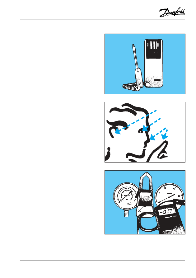
Fault location without
the use of instruments:
After gaining a little experience, many
common faults in a refrigeration system
can be localised visually, by hearing, by
feel, and sometimes by smell.
Other faults can only be detected by
instruments.
Ae0_0028
Categorisation:
This booklet is divided into two sections.
The first section deals exclusively with
faults that can be observed directly with
the senses. Here, symptoms, possible
causes and the effect on operation are
given.
The second section deals with faults that
can be observed directly with the senses,
and those that can only be detected by
instruments. Here, symptoms and
possible causes are given, together with
instructions on remedial action.
Fitters notes
System Trouble Shooting - Fault Location
4
RZ0ZH202
ã Danfoss A/S (RC-CM / MWA), 09 - 2002
Theoretical knowledge is necessary:
A certain amount of theoretical knowledge
is required if faults and incorrect operation
are to be discovered and corrected.
The location of all forms of faults on even
relatively simple refrigeration systems is
conditional on a thorough knowledge of
such factors as:
- The build-up of all components, their
mode of operation and characteristics.
- Necessary measuring equipment and
measuring techniques.
- All refrigeration processes in the
system.
- The influence of the surroundings on
system operation.
- The function and setting of controls and
safety equipment.
- Legislation on the safety of refrigeration
systems and their inspection.
Before examining faults in refrigeration
systems, it could be advantageous to look
briefly at the most important instruments
used in fault location.
Ae0_0034
Ae0_0029
Knowledge of the system is required:
An important element in the fault location
procedure is familiarity with how the
system is built up, its function and control,
both
mechanical and electrical. Unfamiliarity
with the system ought to be remedied by
carefully looking at piping layouts and
other key diagrams and by getting to know
the form of the system (piping, component
placing, and any connected systems, e.g.
cooling towers and brine systems).
Ae0_0033
Fitters notes
System Trouble Shooting - Fault Location
ã Danfoss A/S (RC-CM / MWA), 09 - 2002
RZ0ZH202
5
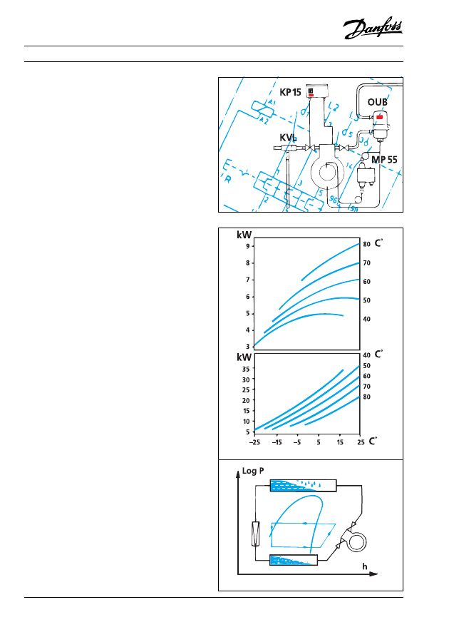
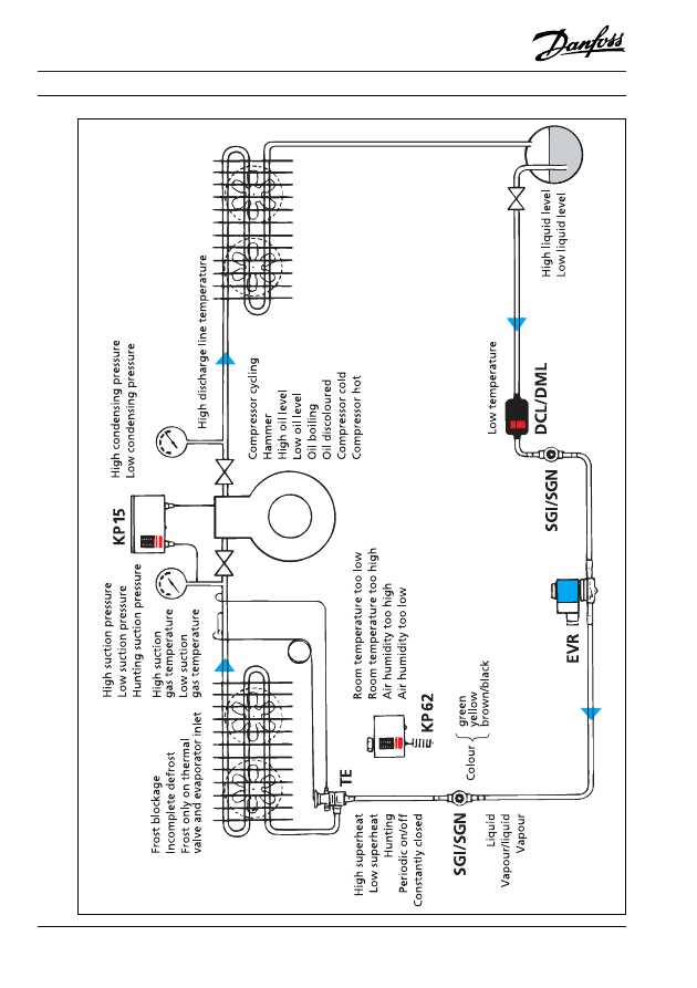
In the following description of faults in
refrigeration systems, sections 1 and 2
take as their starting points the piping
diagrams, figures 1, 2 and 3. The
systems are dealt with in the direction
followed by the circuit. Fault symptoms
that can occur are described in circuit
order. The description starts after the
compressor discharge side and
proceeds in the direction of the arrows.
Ae0_0016
Fitters notes
System Trouble Shooting - Fault Location
6
RZ0ZH202
ã Danfoss A/S (RC-CM / MWA), 09 - 2002
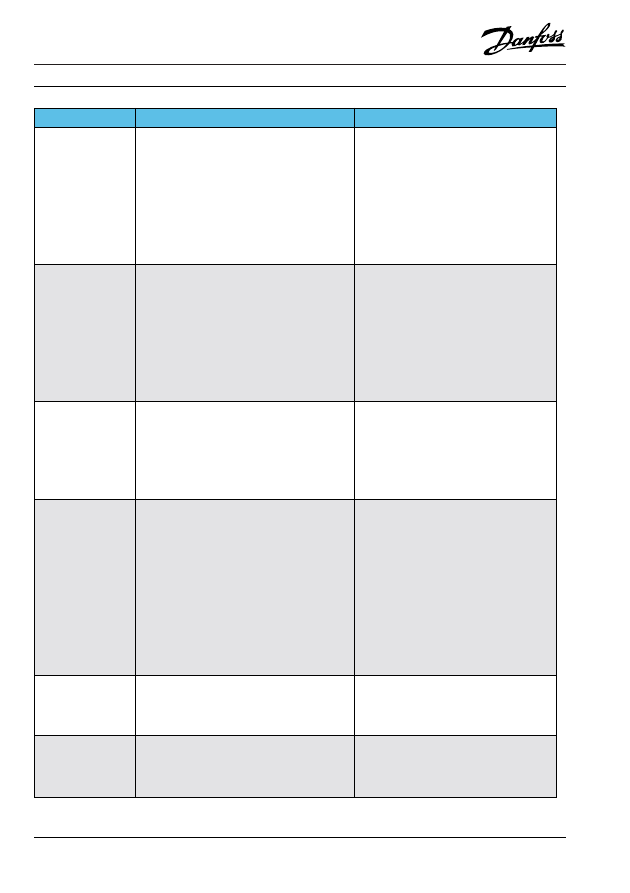
Fault location
Visible Faults
Effect on System Operation
Air-cooled condenser
a) Dirt, e.g. grease or dust, sawdust, dried leaves.
[Lack of maintenance]
b) Fan stopped.
[Motor defect]
[Motor protector cut-out]
c) Fan rotates in wrong direction.
[Installation error]
d) Fan blades damaged.
e) Fins deformed.
[Rough treatment]
Faults under a), b), c), d), e) create:
- Increased condensing pressure
- Reduced refrigeration output.
- Increased energy consumption.
For an air-cooled condenser, the difference between air
inlet and condensing temperatures should lie between
10°C and 20°C, preferably at the lower end.
Water-cooled condenser
with sight glass: See Receiver.
Receiver with sight glass
Liquid level too low.
[Insufficient refrigerant in system]
[Overcharged evaporator]
[Overcharged condenser]
Liquid level too high.
[Overcharged system]
For a water-cooled condenser, the difference between
condensing and water inlet temperatures should lie
between 10°C and 20°C, preferably at the lower end.
Vapour/vapour bubbles in liquid line.
Low suction pressure or compressor cycling.
Excessive condensing pressure possible.
Excessive condensing pressure possible.
Receiver stop valve
a) Valve closed.
b) Valve partly closed.
Liquid line
a) Too small.
[Sizing error]
b) Too long
[Sizing error]
c) Sharp bends and/or deformed
[Installation error]
System stopped via low-pressure control.
Vapour bubbles in liquid line.
Low suction pressure or compressor cycling.
Faults under a), b) and c) cause:
- Large pressure drop in liquid line
- Vapour in liquid line
Filter drier
Dew or frost formation on surface.
[Filter partly blocked with dirt on inlet side]
Sight glass
a) Yellow.
[Moisture in system]
b) Brown.
[Dirt particles in system]
c) Pure vapour in sight glass.
[Insufficient liquid in system]
[Valve in liquid line closed]
[Complete blockage, e.g. of filter drier]
d) Liquid and vapour bubbles in sight glass.
[Insufficient liquid in system]
[Valve in liquid line partly closed]
[Partial blockage, e.g. of filter drier]
[No subcooling]
Vapour in liquid line.
Risk of:
- Acid formation.
- Corrosion.
- Motor burn-out.
- Water freezing in thermostatic expansion valve
Risk of wear in moving parts and blockage in valves
and filters.
Standstill via low-pressure control or compressor
cycling.
Standstill via low-pressure control.
Standstill via low-pressure control.
All faults under d):
Compressor cycling or running at low suction
pressure.
Text in [ ] indicates fault cause
Fitters notes
System Trouble Shooting - Fault Location
ã Danfoss A/S (RC-CM / MWA), 09 - 2002
RZ0ZH202
7
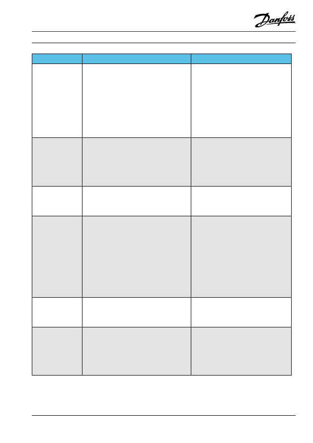
Visible Faults
Effect on System Operation
Thermostatic Expansion Valve
a) Thermostatic expansion valve heavily frosted, frost
on evaporator only near valve.
[Dirt strainer partly blocked]
[Bulb charge partly lost]
[Previously described faults causing
vapour bubbles in liquid line]
b) Thermostatic expansion valve without external
pressure equalisation, evaporator with liquid
distributor.
[Sizing or installation error]
c) Thermostatic expansion valve with external
pressure equalisation, equalising tube not mounted.
[Installation error]
d) Bulb not firmly secured.
[Installation error]
e) Entire bulb length not in contact with tube.
[Installation error]
f) Bulb placed in air current.
[Installation error]
Faults under a) cause operation at low suction pressure
or compressor cycling via low-pressure control..
Faults under b), c) cause operation at low suction
pressure or compressor cycling via low-pressure
control.
Faults under d), e), f) lead to overcharged evaporator
with risk of liquid flow to compressor and compressor
damage.
Air cooler
a) Evaporator frosted only on inlet side, thermostatic
expansion valve heavily frosted.
[Thermal valve fault]
[All previously described faults that cause vapour
in liquid line]
b) Front blocked with frost
[Lacking, incorrect or wrongly set up defrost
procedure]
c) Fan does not run
[Motor defect or motor protector cut-out]
d) Fan blades defective.
e) Fins deformed.
[Rough treatment]
Faults under a) cause:
- High superheat at evaporator outlet and operation
at mostly low suction pressure.
Faults under a), b), c), d), e) cause:
- Operation with mostly low suction pressure
- Reduced refrigeration output.
- Increased energy consumption.
For thermostatic expansion-valve controlled
evaporators:
The difference between air inlet and evaporating
temperatures should lie between 6 K and 15 K,
preferably at the lower end.
For level-controlled evaporators:
The difference between air inlet and evaporating
temperatures should lie between 2 K and 8 K,
preferably at the lower end.
Liquid cooler
a) Thermostatic expansion valve bulb not firmly
secured.
[Installation error]
b) Thermostatic expansion valve without external
pressure equalising on liquid cooler with high
pressure drop, e.g. coaxial evaporator.
[Sizing or installation error]
c) Thermostatic expansion valve with external
pressure equalisation, equalising tube not mounted.
[Installation error]
Causes overcharged evaporator with risk of liquid flow
to compressor and compressor damage.
Faults b), c) cause:
- High superheat at evaporator outlet.
- Operation at mostly low suction pressure.
- Reduced refrigeration output.
- Increased energy consumption.
For thermostatic expansion valve controlled
evaporators:
The difference between air inlet and evaporating
temperatures should lie between 6 K and 15 K,
preferably at the lower end.
For level-controlled evaporators:
The difference between air inlet and evaporating
temperatures should lie between 2 K and 8 K,
preferably at the lower end.
Fitters notes
System Trouble Shooting - Fault Location
8
RZ0ZH202
ã Danfoss A/S (RC-CM / MWA), 09 - 2002
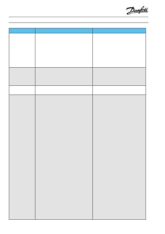
Visible Faults
Effect on System Operation
Suction line
a) Abnormally severe frosting.
[Thermal valve superheat too low]
b) Sharp bends and/or deformation
[Installation error]
Regulators in suction line
Dew/frost after regulator, no dew/frost ahead of
regulator.
[Thermal valve superheat too low]
Risk of liquid flow to compressor and compressor
damage.
Low suction pressure or compressor cycling.
Risk of liquid flow to compressor and compressor
damage.
Compressor
a) Dew or frost on compressor inlet side.
[Superheat at evaporator outlet too low]
b) Oil level too low in crankcase.
[Insufficient oil in system]
[Oil collection in evaporator]
c) Oil level too high in crankcase.
[Oil overfilling]
[Refrigerant mixed with oil in too cold a
compressor]
[Refrigerant mixed with oil because superheat too
low at evaporator outlet]
d) Oil boils in crankcase during start.
[Refrigerant mixed with oil in too cold a
compressor]
e) Oil boils in crankcase during operation.
[Refrigerant mixed with oil because superheat too
low at evaporator outlet]
Liquid flow to compressor with risk of compressor
damage.
System stop via oil differential pressure control (if fitted).
Causes wear of moving parts.
Liquid hammer in cylinders, risk of compressor
damage:
- Damage to working valves.
- Damage to other moving parts.
- Mechanical overload.
Liquid hammer, damage as under c)
Liquid hammer, damage as under c)
Cold Room
a) Dry surface on meat, limp vegetables.
[Air humidity too low - evaporator probably too
small]
b) Door not tight, or defective.
c) Defective or missing alarm sign.
d) Defective or missing exit sign.
For b), c), d):
[Lack of maintenance or sizing error]
e) No alarm system.
[Sizing error]
Leads to poor food quality and/or wastage.
Can give rise to personal injury.
Can give rise to personal injury.
Can give rise to personal injury.
Can give rise to personal injury.
General
a) Oil drops under joints and/or oil spots on floor.
[Possible leakage at joints]
b) Blown fuses.
[Overload on system or short-circuiting]
c) Motor protector cut-out.
[Overload on system or short circuiting]
d) Cut-out pressure controls or thermostats, etc.
[Setting error]
[Equipment defect]
Oil and refrigerant leakage.
System stopped.
System stopped.
System stopped.
System stopped.
Fitters notes
System Trouble Shooting - Fault Location
ã Danfoss A/S (RC-CM / MWA), 09 - 2002
RZ0ZH202
9
Faults that can be Felt
Effect on System Operation
Solenoid valve
Colder than the tubing ahead of the solenoid valve.
[Solenoid valve sticks, partly open]
Same temperature as tubing ahead of solenoid valve.
[Solenoid valve closed]
Vapour in liquid line.
System stopped via low-pressure control.
Filter drier
Filter colder than tubing ahead of filter.
[Filter partly blocked with dirt on inlet side]
Vapour in liquid line.
Faults that can he heard
Effect on System Operation
Regulators in suction line
Whining sound from evaporating pressure regulator
or another regulator.
[Regulator too large (sizing error)]
Unstable operation.
Compressor
a) Knocking sound on starting.
[Oil boiling]
b) Knocking sound during operation.
[Oil boiling]
[Wear on moving parts]
Cold room
Defective alarm system.
[Lack of maintenance]
Liquid hammer.
Risk of compressor damage.
Liquid hammer.
Risk of compressor damage.
Can give rise to personal injury.
Faults that can he smelled
Effect on System Operation
Cold room
Bad smell in meat cold room.
[Air humidity too high because evaporator too large
or load too low]
Leads to poor food quality and/or wastage.
Fitters notes
System Trouble Shooting - Fault Location
10
RZ0ZH202
ã Danfoss A/S (RC-CM / MWA), 09 - 2002
Ae0_0019_02
Refrigeration
System
with
Air
Cooler
and
Air-cooled
Condenser
Fig.
1
Fitters notes
System Trouble Shooting - Fault Location
ã Danfoss A/S (RC-CM / MWA), 09 - 2002
RZ0ZH202
11
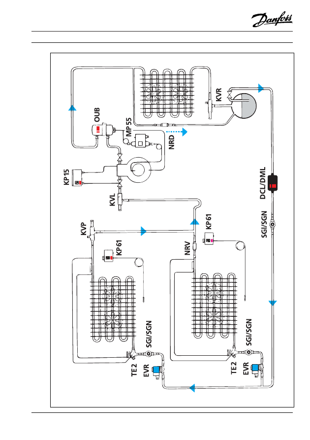
Ae0_0030
Refrigeration
System
with
two
Air
Coolers
and
Air-cooled
Condenser
Fig.
2
Fitters notes
System Trouble Shooting - Fault Location
12
RZ0ZH202
ã Danfoss A/S (RC-CM / MWA), 09 - 2002
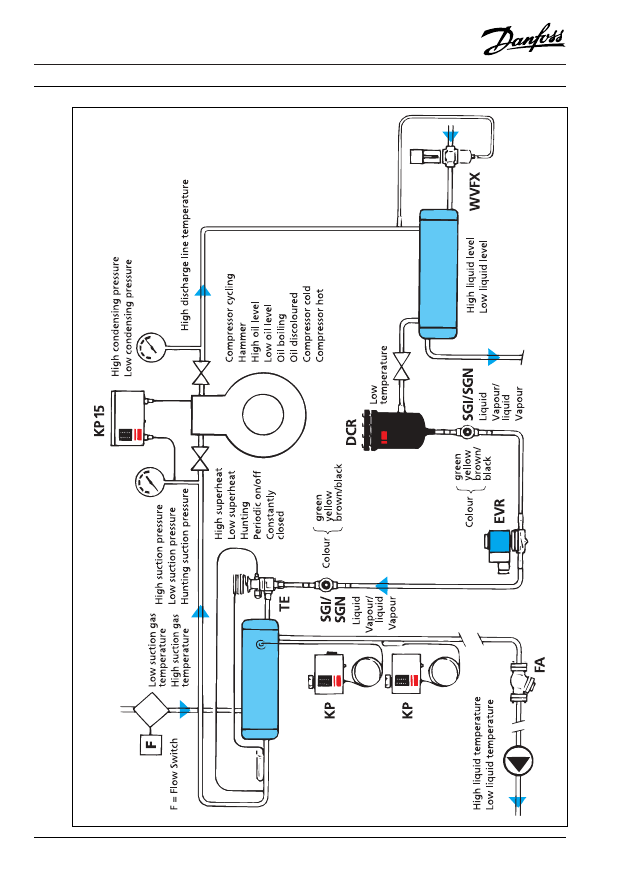
Ae0_0035_02
Refrigeration
System
with
Liquid
Cooler
and
Water-cooled
Condenser
Fig.
3
Fitters notes
System Trouble Shooting - Fault Location
ã Danfoss A/S (RC-CM / MWA), 09 - 2002
RZ0ZH202
13
Follow the arrows in the diagrams, figs. 1 and 3, p. 10/12.
Begin after the compressor
Page
High condensing pressure ........................................................................................... 14
Low condensing pressure ............................................................................................ 14
Hunting condensing pressure ...................................................................................... 15
High discharge line temperature .................................................................................. 15
Low discharge line temperature ................................................................................... 15
Low liquid level in receiver ............................................................................................ 15
High liquid level in receiver ........................................................................................... 15
Refrigeration output too small ...................................................................................... 15
Low temperature on filter drier ...................................................................................... 16
Sight glass moisture indicator - discoloured, yellow ................................................... 16
Sight glass moisture indicator - brown or black ........................................................... 16
Vapour bubbles in sight glass ahead of thermostatic expansion valve ....................... 16
Evaporator blocked by frost ........................................................................................... 17
Evaporator frosted only on line near thermostatic expansion valve ............................. 17
Air humidity in cold room too high ................................................................................. 17
Air humidity in cold room too low .................................................................................. 17
Air temperature in room too high .................................................................................. 18
Air temperature in room too low .................................................................................... 18
High suction pressure .................................................................................................. 18
Low suction pressure ................................................................................................... 18
Hunting suction pressure ............................................................................................. 19
High suction gas temperature ...................................................................................... 19
Low suction gas temperature ....................................................................................... 20
Compressor cycling ...................................................................................................... 20
Discharge tube temperature too high ........................................................................... 20
Compressor too cold .................................................................................................... 20
Compressor too hot ...................................................................................................... 20
Compressor knocking .................................................................................................. 20
Compressor oil level high ............................................................................................. 21
Compressor oil level low .............................................................................................. 21
Compressor oil boils .................................................................................................... 21
Compressor oil discoloured ......................................................................................... 22
Compressor will not start .............................................................................................. 22
Compressor runs constantly ........................................................................................ 23
Fitters notes
System Trouble Shooting - Fault Location
14
RZ0ZH202
ã Danfoss A/S (RC-CM / MWA), 09 - 2002
Symptom
Possible cause
Remedy
Condensing
pressure too high.
Air- and
water-cooled
condensers.
a) Air or other non-condensable gases in
refrigerant system.
b) Condenser surface too small.
c) Refrigerant system charge too large (liquid
collection in condenser).
d) Condensing pressure regulation set for too
high a pressure.
Purge the condenser by using reclaim
system, start and run system until it
reaches running temperature. Purge again
if necessary.
Replace condenser with larger size.
Recover refrigerant until condensing
pressure is normal. The sight glass must
remain full.
Set for the correct pressure.
Condensing
pressure too high.
Air-cooled
condensers.
a) Dirt on condenser surface.
b) Fan motor or blade defective or too small.
c) Air flow to condenser restricted.
d) Ambient temperature too high.
e) Incorrect air flow direction through
condenser.
f) Short-circuit between condenser fan airside
pressure and suction sides.
Clean condenser.
Replace motor or fan blade or both.
Remove air inlet obstruction or move
condenser.
Create fresh air inlet or move condenser.
Change rotation of fan motor. On
condensing units, air must flow through
condenser and then to compressor.
Install a suitable duct, possibly to outdoor
air.
Condensing
pressure too high.
Water-cooled
condensers.
a) Cooling water temperature too high.
b) Water quantity too small.
c) Deposits on inside of water pipes (scale etc).
d) Cooling water pump defective or stopped.
Ensure lower water temperature.
Increase water quantity, possibly using
automatic water valve.
Clean out condenser water tubes, possibly
by deacidification
Investigate cause, replace or repair cooling
water pump if fitted.
Condensing
pressure too low.
Air- and water-
cooled
condensers.
a) Condenser surface too large.
b) Low load on evaporator.
c) Suction pressure too low, e.g. insufficient
liquid in evaporator.
d) Compressor suction and discharge valves
might be leaking.
e) Condensing pressure regulator set for too
low a pressure.
f) Un-insulated receiver placed too cold in
relation to condenser (receiver acts as
condenser).
Establish condensing pressure regulation
or replace condenser.
Establish condensing pressure regulation.
Locate fault on line between condenser and
thermostatic expansion valve (see "Suction
pressure too low").
Replace compressor valve plate.
Set condensing pressure regulator for
correct pressure.
Move receiver or fit it with suitable
insulating cover.
Condensing
pressure too low.
Air-cooled
condensers.
a) Temperature of cooled air too low.
b) Air quantity for condenser too large.
Establish condensing pressure regulation.
Replace fan with smaller unit or establish
motor speed regulation.
Condensing
pressure too low.
Water-cooled
condensers.
a) Water quantity too large.
b) Water temperature too low.
Install WVFX automatic water valve or
set existing valve.
Reduce water quantity by using a WVFX
automatic water valve, for example.
Fitters notes
System Trouble Shooting - Fault Location
ã Danfoss A/S (RC-CM / MWA), 09 - 2002
RZ0ZH202
15
Symptom
Possible cause
Remedy
Condensing
pressure hunts.
a) Differential on start/stop pressure control
for condenser fan too large. Can cause
vapour formation in liquid line for some
time after start of condenser fan because of
refrigerant collection in condenser.
b) Thermostatic expansion valve hunting.
c) Fault in KVR/KVD condensing pressure
regulating valves (orifice too large).
d) Consequence of hunting suction pressure.
Set differential on lower value or use valve
regulation (KVD + KVR) or use fan motor
speed regulation.
Set thermostatic expansion valve for
higher superheat or replace orifice with
smaller size.
Replace valves with smaller size.
See "Suction pressure hunts".
Discharge line
temperature too
high.
a) Suction pressure too low because of:
1) Insufficient liquid in evaporator.
2) Low evaporator load.
3) Leaking suction or discharge valves.
4) Superheat too high in heat exchanger or
suction accumulator in suction line.
b) Condensing pressure too high.
Locate fault on line from receiver to suction
line (see "Suction pressure too low").
Ditto.
Replace compressor valve plate.
Omit heat exchange or possibly select
smaller heat exchanger.
See "Condensing pressure too high".
Discharge line
temperature too
low.
a) Liquid flow to compressor (thermal valve
superheat setting too low or bulb location
incorrect).
b) Condensing pressure too low.
See "Fitters notes, Thermostatic
expansion valves: Fault location".
See "Condensing pressure too low".
Liquid level in
receiver too low.
a) Insufficient refrigerant in system.
b) Evaporator overcharged.
1) Low load, leading to refrigerant
collection in evaporator.
2) Thermostatic expansion valve fault (e.g.
superheat setting too low, bulb location
wrong).
c) Refrigerant collection in condenser because
condensing pressure lower than receiver
pressure (receiver placed warmer than
condenser)
Investigate cause (leakage, overcharge in
evaporator), repair fault and charge system
if necessary.
See "Fitter notes, Thermostatic expansion
valves: Fault location".
See "Fitters notes, Thermostatic
expansion valves: Fault location".
Place receiver together with condenser.
Air-cooled condensers: Establish
condensing pressure regulation by fan
motor speed regulation, e.g. type VLT.
Liquid level in
receiver too high.
Refrigeration
output normal.
Refrigerant charge in system too large.
Recover a suitable quantity of refrigerant,
but condensing pressure must remain
normal and the sight glass free of vapour.
Liquid level in
receiver too high.
Refrigeration
output too low
(possible
compressor
cycling)
a) Partial blockage of a component in liquid
line.
b) Thermostatic expansion valve fault (e.g.
superheat too high, orifice too small, lost
charge, partial blockage).
Find the component and clean or replace
it.
See "Fitters notes, Thermostatic
expansion valves: Fault location".
Fitters notes
System Trouble Shooting - Fault Location
16
RZ0ZH202
ã Danfoss A/S (RC-CM / MWA), 09 - 2002
Symptom
Possible cause
Remedy
Filter drier cold,
dew or frosting
possible.
a) Partial blocking of dirt strainer in filter
drier.
b) Filter drier completely or partly saturated
with water or acid.
Check whether there are impurities in the
system, clean out where necessary, replace
filter drier.
Check whether there is moisture or acid in
the system, clean out where necessary and
replace filter drier (burn-out filter) several
times if necessary. If acid contamination is
severe, replace refrigerant and oil charge,
install DCR filter drier with interchange-
able core in suction line.
Moisture indicator
discoloured.
Yellow.
Moisture in system.
Check system for leakage. Repair if
necessary. Check system for acid.
Replace filter drier, several times if
necessary. In severe cases it can be
necessary to change refrigerant and oil.
Brown or black.
Impurities, i.e. small particles in system.
Clean out system if necessary.
Replace SGI sight glass and filter drier.
Vapour bubbles in
sight glass ahead
of thermostatic
expansion valve.
a) Insufficient liquid subcooling from large
pressure drop in liquid line because:
1) Liquid line too long in relation to
diameter.
2) Liquid line diameter too small.
3) Sharp bends, etc. in liquid line.
4) Partial blockage of filter drier.
5) Solenoid valve defect.
b) Insufficient liquid subcooling because of
heat penetration of liquid line, possibly
from high temperature around liquid line.
c) Water-cooled condensers: Insufficient
subcooling because of wrong cooling water
flow direction.
d) Condensing pressure too low.
e) Receiver stop valve too small or not fully
open.
f) Hydrostatic pressure drop in liquid line
too high (height difference between
thermostatic expansion valve and receiver
too large).
g) Badly or incorrectly set condensing
pressure regulation causing liquid
collection in condenser.
h) Condenser pressure regulation by start/
stop of condenser fan can cause vapour in
liquid line for some time after fan start.
i) Insufficient liquid in system.
Replace liquid line with tube of suitable
diameter.
Replace liquid line with tube of suitable
diameter.
Replace sharp bends and components
causing too large a pressure drop.
Check for impurities, clean out if
necessary, replace filter drier.
See "Fitters notes, Solenoid valves.
Reduce ambient temperature or install heat
exchanger between liquid and suction lines
or insulate liquid line, possibly together
with suction line.
Swap over cooling water inlet and outlet.
(Water and refrigerant flow must be
opposite).
See "Condensing pressure too low".
Replace valve or open it fully.
Install heat exchanger between liquid and
suction lines ahead of rise in liquid line.
Replace or reset KVR regulator at correct
value.
If necessary, replace regulation with
condensing pressure regulation via valves
(KVD + KVR) or with fan motor speed
regulation, type VLT.
Recharge system, but first make sure that
none of the faults named under a), b), c),
d), e), f), g), h) are present, otherwise there
is a risk of the system becoming
overcharged. See "Fitters notes, Installa-
tion: Refrigerant charging".
Fitters notes
System Trouble Shooting - Fault Location
ã Danfoss A/S (RC-CM / MWA), 09 - 2002
RZ0ZH202
17
Symptom
Possible cause
Remedy
Air coolers.
Evaporator
blocked by
frost.
a) Lack of or poor defrost procedure.
b) Air humidity in cold room too high
because of moisture load from:
1) Unpackaged items.
2) Air ingress into room through fissures
or open door.
Install defrost system or adjust defrost
procedure.
Recommend packaging of items or adjust
defrost procedure.
Repair fissures. Recommend that door be
kept closed.
Air coolers.
Evaporator
frosted only on
line near
thermostatic
expansion valve,
severe frost on
thermostatic
expansion valve.
Refrigerant supply to evaporator too small
because of:
a) Thermostatic expansion valve defect, e.g.
1) Orifice too small.
2) Superheat too high.
3) Partial loss of bulb charge.
4) Dirt strainer partly blocked.
5) Orifice partly blocked by ice.
b) Fault as described under "Vapour bubbles
in sight glass".
See "Fitters notes, Expansion valves:
Fault location".
See "Vapour bubbles in sight glass".
Air coolers.
Evaporator
damaged.
Fins deformed.
Straighten fins using a fin comb.
Air humidity in
cold room too
high, room
temperature
normal.
a) Evaporator surface too large. Causes
operation at excessive evaporating
temperature during short running periods.
b) Load on room too low, e.g. during winter
(insufficient dehumidification because of
short total running time per 24 hours).
Replace evaporator with smaller size.
Establish humidity regulation with
hygrometer, heating elements and KP62
safety thermostat.
Air humidity in
room too low.
a) Cold room poorly insulated.
b) High internal energy consumption, e.g.
lights and fans.
c) Evaporator surface too small, causes long
running times at mainly low evaporating
temperatures.
Recommend improved insulation.
Recommend less internal energy
consumption.
Replace evaporator with larger size.
Fitters notes
System Trouble Shooting - Fault Location
18
RZ0ZH202
ã Danfoss A/S (RC-CM / MWA), 09 - 2002
Symptom
Possible cause
Remedy
Air temperature
in cold room too
high.
a) Room thermostat defect.
b) Compressor capacity too small.
c) Load on room too high because of:
1) Loading of non-cooled items.
2) High energy consumption, e.g. for
lights and fans.
3) Cold room poorly insulated.
4) High air ingress.
d) Evaporator too small.
e) Insufficient or no refrigerant supply to
evaporator.
f) Evaporating pressure regulator set for too
high an evaporating pressure.
g) Cut-out pressure on low-pressure control
set too high.
h) Capacity regulating valve opens at too
high an evaporating pressure.
i) Opening pressure of crankcase pressure
regulator set too low.
See "Fitters notes, Thermostats: Fault
location".
See "Compressor".
Recommend placing of smaller load or
increased system capacity.
Recommend reduction of energy consump-
tion or increased system consumption.
Recommend better insulation.
Recommend repair of fissures and least
possible door opening.
Replace evaporator with larger size.
See "Vapour bubbles in sight glass ahead
of thermal valve" and "Fitters notes,
Thermostatic expansion valves: Fault
location".
Set evaporating pressure regulator at
correct value. Use a pressure gauge.
Set low-pressure control at correct cut-out
pressure. Use a pressure gauge.
Set capacity regulating valve at lower
opening pressure.
Set valve for higher opening pressure if
the compressor will withstand it.
Air temperature
in cold room too
low.
a) Room thermostat defect:
1) Cut-out temperature set too low.
2) Bulb location wrong.
b) Ambient temperature very low.
See "Fitters notes, Thermostats: Fault
location"
If absolutely necessary, establish
thermostat controlled electrical heating.
Suction pressure
too high.
a) Compressor too small.
b) One or more compressor disc valves
leaking.
c) Capacity regulation defective or incorrectly
set.
d) System load too high.
e) Hot gas defrost valve leaking.
Replace compressor with larger size.
Replace valve plate.
Replace, repair or adjust capacity
regulation.
Recommend less load or replace compres-
sor with larger size, or install KVL
crankcase pressure regulator.
Replace valve.
Suction pressure
too high and
suction gas
temperature too
low.
a) Thermostatic expansion valve superheat
setting too low or bulb located incorrectly.
b) Thermostatic expansion valve orifice too
large.
c) Leaking liquid line in heat exchanger
between liquid and suction lines.
See "Fitters notes, Thermostatic
expansion valves: Fault location".
Replace orifice with smaller size.
Replace HE heat exchanger.
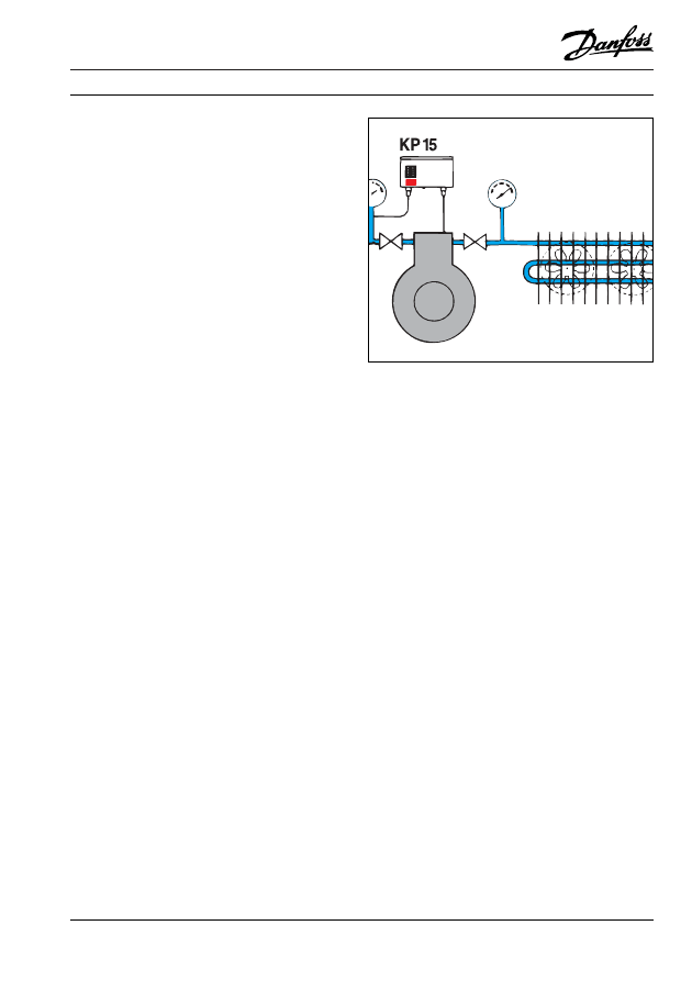
Suction pressure
too low, constant
running.
Low-pressure control set incorrectly, or
defective.
Adjust or replace low-pressure control
KP 1 or combined pressure control KP 15.
Fitters notes
System Trouble Shooting - Fault Location
ã Danfoss A/S (RC-CM / MWA), 09 - 2002
RZ0ZH202
19
Symptom
Possible cause
Remedy
Suction pressure
too low, normal
operation or
compressor
cycling.
a) Low system load.
b) Insufficient refrigerant in evaporator,
because of:
1) Insufficient refrigerant in receiver.
2) Liquid line too long.
3) Liquid line too small.
4) Sharp bends, etc. in liquid line.
5) Filter drier partly blocked.
6) Solenoid valve sticks.
7) Inadequate liquid subcooling.
8) Fault at thermal valve.
c) Evaporator too small.
d) Evaporator fan defective.
e) Pressure drop in evaporator and/or suction
line too large.
f) Lack of or inadequate defrosting of air
cooler.
g) Freezing in brine cooler.
h) Insufficient air or brine through cooler
i) Oil collection in evaporator.
Establish capacity regulation or increase
lowpressure control differential.
See "Liquid level in receiver too low".
See "Vapour bubbles in sight glass."
Ditto.
Ditto.
See "Vapour bubbles in sight glass".
Ditto.
Ditto.
See "Fitters notes, Thermostatic expansion
valves: Fault location".
Replace with larger evaporator.
Replace or repair fan.
If necessary, replace evaporator and/or
suction line.
Establish a defrost system or adjust defrost
procedure.
Increase brine concentration and check frost
protection equipment.
Check cause and correct fault. See "Air
coolers" and "Liquid coolers".
See "Oil level in crankcase ton low"
Suction pressure
hunts.
Thermostatic
expansion valve
operation.
a) Thermostatic expansion valve superheat
too low
b) Thermostatic expansion valve orifice too
large.
c) Capacity regulation fault
1) Capacity regulating valve too large.
2) Pressure control(s) for stage regulation
incorrectly set.
See "Fitters notes, Thermostatic expansion
valves: Fault location".
Replace KVC capacity regulating valve
with smaller size.
Set for greater difference between cut-in and
cut-out pressures.
Suction pressure
hunts.
Electronic
expansion valve
operation.
Hunting normal
None
Suction gas
temperature too
high
Refrigerant supply to evaporator too small
because:
a) System refrigerant charge too small.
b) Defect in liquid line or components in that
line
c) Thermostatic expansion valve superheat
setting too high, or bulb charge partly
lost.
Charge refrigerant to correct level.
See "Fitters notes, Installation, refrigerant
charging".
See these entries: "Liquid level in
receiver", "Filter drier cold", "Vapour
bubbles in sight glass", "Suction pressure
too low".
See "Fitters notes, Thermostatic expansion
valves: Fault location".
Fitters notes
System Trouble Shooting - Fault Location
20
RZ0ZH202
ã Danfoss A/S (RC-CM / MWA), 09 - 2002
Symptom
Possible cause
Remedy
Suction gas
temperature too
low.
Refrigerant supply to evaporator too large
because:
a) Thermostatic expansion valve superheat
set too low.
b) Thermostatic expansion valve bulb located
incorrectly (too warm or in poor contact
with piping).
See "Fitters notes , Thermostatic
expansion valves: Fault location".
See "Fitters notes , Thermostatic
expansion valves: Fault location".
Compressor
Compressor
cycling (cut-out
via low- pressure
control).
a) Compressor capacity too high in relation
to load at any given time.
b) Compressor too large.
c) Opening pressure of evaporating pressure
regulator set too high.
Establish capacity regulation using KVC
capacity regulating valve or parallel-
coupled compressors.
Replace compressors with smaller size.
Using a pressure gauge, set KVP regulator
at correct value.
Compressor
Compressor
cycling (cut-out
via high-
pressure control).
a) Condensing pressure too high.
b) High-pressure control defect.
c) High-pressure control cut-out set too low.
See "Condensing pressure too high".
Replace high-pressure control KP 5 or
combined pressure control KP 15.
Using a pressure gauge, set pressure
control at correct value.
Avoid compressor cycling by using high-
pressure control with manual reset.
Discharge pipe
temperature too high
Suction and/or discharge valve (working
valves) not tight.
Replace valve plate. See also "Discharge
temperature too high".
Compressor
Compressor too
cold.
Flow of liquid refrigerant from evaporator to
suction line and possibly to compressor
because of incorrectly set thermostatic
expansion valve.
Set thermostatic expansion valve for lower
superheat using MSS method, see
"Thermostatic expansion valves, Setting
and fault location".
Compressor
Compressor too
hot.
a) Compressor and possibly motor
overloaded because evaporator load and
thereby suction pressure too high.
b) Poor motor and cylinder cooling because
of:
1) Insufficient liquid in evaporator.
2) Low evaporator load.
3) Suction and discharge valves not tight.
4) Superheat too severe in heat exchanger,
or in suction accumulator in suction
line.
c) Condensing pressure too high.
Reduce evaporator load or replace
compressor with larger size.
Locate fault on line between condenser and
thermostatic expansion valve (see "Suction
pressure too low").
Ditto
Replace valve plate.
Omit heat exchange or possibly select
smaller HE heat exchanger.
See "Condensing pressure too high".
Knocking sound:
a) Constant.
b) During start.
a) Liquid hammer in cylinder because of
liquid flow to compressor.
b) Oil boiling because of liquid build up in
crankcase.
c) Wear on moving compressor parts,
especially bearings.
Set thermostatic expansion valve for lower
superheat using MSS method.
Install heating element in or under
compressor crankcase.
Repair or replace compressor.
Fitters notes
System Trouble Shooting - Fault Location
ã Danfoss A/S (RC-CM / MWA), 09 - 2002
RZ0ZH202
21
Symptom
Possible cause
Remedy
Compressor.
Oil level in
crankcase too
high.
On high load,
otherwise not.
During standstill
or start..
Oil quantity too large.
Refrigerant absorption in crankcase oil
because of too low an ambient temperature.
Drain oil to correct level, but first ensure
that the large quantity is not due to
refrigerant absorption in the oil.
Install heating element in or under
compressor crankcase.
Compressor.
Oil level in
crankcase too
low.
a) Oil quantity too small.
b) Poor oil return from evaporator because:
1) Diameter of vertical suction lines too
large.
2) No oil separator.
3) Insufficient fall on horizontal suction
line.
c) Wear on piston/piston rings and cylinder.
d) On parallel-coupled compressors:
1) With oil equalising tube:
Compressors not on same horizontal
plane. Equalising pipe too small.
2) With oil level regulation:
Float valve partly or wholly blocked.
Float valve sticking.
e) Oil return from oil separator partly or
wholly blocked, or float valve sticking.
Fill oil to correct level, but first be sure
that the oil quantity in the crankcase is
not a result of oil collection in the
evaporator. Install oil lock at 1.2 m to 1.5
m from vertical suction lines. If liquid
supply is at the bottom of the evaporator
it can be necessary to swap inlet and
outlet tubes (liquid supply uppermost).
See also "Fitters notes, Installation".
Replace worn components.
In all circumstances: the compressor
started last is most subject to oil
starvation. See also Fitters notes,
Installation".
Line up compressors so that they are in
same horizontal plane.
Install larger equalising pipe. Fit vapour
equalising pipe if necessary.
Clean or replace level container with float
valve.
Ditto
Clean or replace oil return pipe or replace
float valve or whole oil separator.
Compressor
Oil boils during
start.
a) High refrigerant absorption in crankcase
oil because of low ambient temperature.
b) Systems with oil separator: Too much
absorption of refrigerant in oil in separator
during standstill.
Install heating element in or under
compressor crankcase.
Oil separator too cold during start. Install
thermostat-controlled heating element or
solenoid valve with time delay in oil
return tube. Fit non return valve in
discharge pipe after oil separator.
Compressor.
Oil boiling
during
operation.
a) Flow of liquid refrigerant from evaporator
to compressor crankcase.
b) Systems with oil separator: Float valve
not closing completely.
Set thermostatic expansion valve for
higher superheat using MSS method.
Replace float valve or whole oil separator.
Fitters notes
System Trouble Shooting - Fault Location
22
RZ0ZH202
ã Danfoss A/S (RC-CM / MWA), 09 - 2002
Symptom
Possible cause
Remedy
Compressor.
Oil discoloured.
System contamination arising from:
a) Cleanliness not observed during
installation.
b) Oil breakdown because of moisture in
system.
c) Oil breakdown because of high discharge
pipe temperature.
d) Wear particles from moving parts.
e) Inadequate cleaning after motor burn-out.
In all circumstances: Change oil and filter
drier.
Clean out refrigerant system if necessary.
Clean out refrigerant system if necessary.
Locate and remedy cause of excessive
discharge pipe temperature. See "Discharge
pipe temperature too high". Clean out
system if necessary.
Clean out refrigerant system if necessary.
Replace worn parts or install new
compressor.
Clean out refrigerant system. Fit DA
"burn-out" filter. Replace filter several
times if necessary.
Compressor.
Will not start.
a) Insufficient or no voltage for fuse group.
b) Blown group fuses.
c) Fuse in control circuit blown.
d) Main switch not on.
e) Thermal protection in motor starter cut out or
defective, e.g. as a result of:
1) Excessive suction pressure.
2) Condensing pressure too high.
3) Dirt or copper deposition in compressor
bearings, etc.
4) Supply voltage too low.
5) Single phase drop out.
6) Short-circuited motor windings (motor
burn-out).
f) Motor winding protectors cut out because
of excessive current consumption.
g) Contactors in motor starter burnt out
because:
1) Starting current too high.
2) Contactor undersized.
h) Other safety equipment cut out, incorrectly
set or defective:
Oil differential control.
(no oil, oil boiling).
High-pressure control.
Low-pressure control.
Flow switch.
(insufficient brine concentration, brine
pump failure, blocked brine circuit
filter, evaporating temperature too low).
Frost protection thermostat
(insufficient brine concentration, brine
pump failure, blocked brine circuit filter,
evaporating temperature too low).
i) Regulating equipment cut out, incorrectly
set or defective:
Low-pressure control,
Room thermostat
Telephone electricity company.
Locate fault. Have fault repaired and change
fuses.
Locate fault. Have fault repaired and change
fuses.
Switch on.
Locate and repair fault or replace protector.
See "Suction pressure too high".
See "Condensing pressure too high".
Clean out refrigerant system, replace
compressor and filter drier.
Telephone electricity company.
Locate and remedy fault (often blown fuse).
Clean out refrigerant system if necessary,
replace compressor and filter drier.
Locate and remedy cause of excessive current
consumption, start system when windings
have cooled down (can take a long time).
Locate and remedy cause of motor overload,
replace contactor.
Replace contactor with larger size.
In all circumstances, locate and repair fault
before starting system:
See "Compressor, Oil level too low" and
"Compressor, Oil boiling....
See "Condensing pressure too high".
See "Suction pressure too low".
Locate and remedy cause of reduced or no
flow in brine circuit. See "Liquid coolers".
Locate and remedy cause of excessively low
temperature in brine circuit. See "Liquid
coolers".
Locate and repair fault. Start system. See
"Suction pressure too low" and "Fitters
notes, Pressure controls: Fault location".
See "Fitters notes, Thermostats, Fault
location".
Fitters notes
System Trouble Shooting - Fault Location
ã Danfoss A/S (RC-CM / MWA), 09 - 2002
RZ0ZH202
23
Symptom
Possible cause
Remedy
Compressor.
Will not start.
j) Motor windings burnt out.
Open compressor:
Compressor and motor overloaded.
Motor undersized
Hermetic and semihermetic compressor:
Compressor and motor overloaded.
Acid formation in refrigerant system.
k) Bearing or cylinder seizing because of:
1) Dirt particles in refrigerant system.
2) Copper deposition on machined parts
because of acid formation in refrigerant
system.
3) Insufficient or no lubrication as a result
of:
- Defective oil pump.
- Oil boiling in crankcase.
- Insufficient oil.
- Oil collection in evaporator.
- Poor or no oil equalisation between
parallel-coupled compressors (oil
starvation in compressor started
last).
Locate and remedy cause of overload,
replace motor.
Replace motor with larger size.
Locate and remedy cause of overload,
replace compressor.
Locate and remedy cause of acid formation,
remove compressor, clean out refrigerant
system if necessary, fit new "burn-out"
filter, refill with oil and refrigerant, install
new compressor.
Clean out system and install new filter
drier and new compressor.
Clean out system and install new filter
drier and new compressor.
In all circumstances: Locate and remedy
the fault, replace defective parts or install
new compressor.
See "Compressor, Oil boiling--.
See "Compressor, Oil level in crankcase
too low".
See "Compressor, Oil level in crankcase
too low".
See "Compressor, Oil level in crankcase
too low" and "Fitters notes, Installation".
Compressor runs
constantly, suction
pressure too low.
Cut-out pressure of low-pressure control set
too low, or defective control.
See "Suction pressure too low".
Compressor runs
constantly, suction
pressure too high..
a) Compressor suction and/or discharge valve
not tight.
b) Compressor capacity too low in relation to
load at any given time.
Replace valve plate.
Recommend lower load, or replace
compressor with larger size.
RZ0ZH202
ã Danfoss A/S (RC-CM / MWA), 09 - 2002
Danfoss can accept no responsibility for possible errors in catalogues, brochures and other printed material. Danfoss reserves the right to alter its products without notice. This also applies to
products already on order provided that such alterations can be made without subsequential changes being necessary in specifications already agreed.
All trademarks in this material are property of the respective companies. Danfoss and the Danfoss logotype are trademarks of Danfoss A/S. All rights reserved.
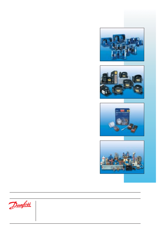
Refrigeration and air conditioning controls
Our full product range covers all control, safety, system
protection and monitoring requirements in mechanically and
electronically controlled refrigeration and air conditioning
systems. The products are used in countless applications
within the commercial and industrial refrigeration and air
conditioning sectors.
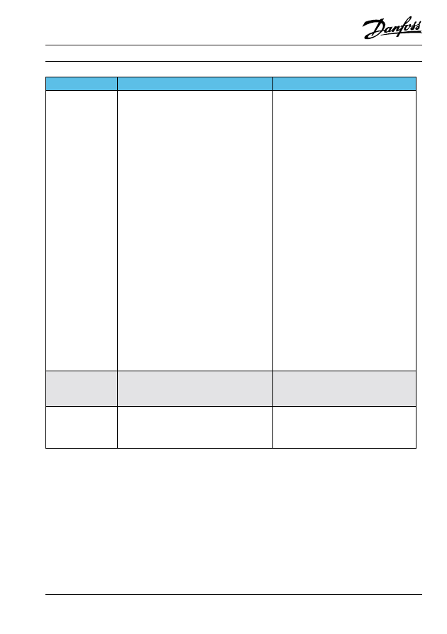
Appliance controls
For the regulation of refrigeration appliances and freezers
Danfoss supplies a product range of electromechanical
thermostats produced according to customer specifications;
electronic temperature controls comprising models with and
without displays; service thermostats – for servicing on all
refrigerating and freezing appliances.
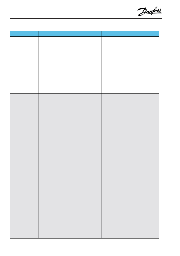
Compressors and Condensing Units
This part of the range includes hermetic compressors and fan-
cooled condensing units for household refrigerators and
freezers, and for commercial units such as bottle coolers and
drinks dispensers. We also offer compressors for heat pumps,
and 12 and 24 V compressors for refrigerators and freezers in
commercial vehicles and boats.
The Danfoss product range for the refrigeration
and air conditioning industry:
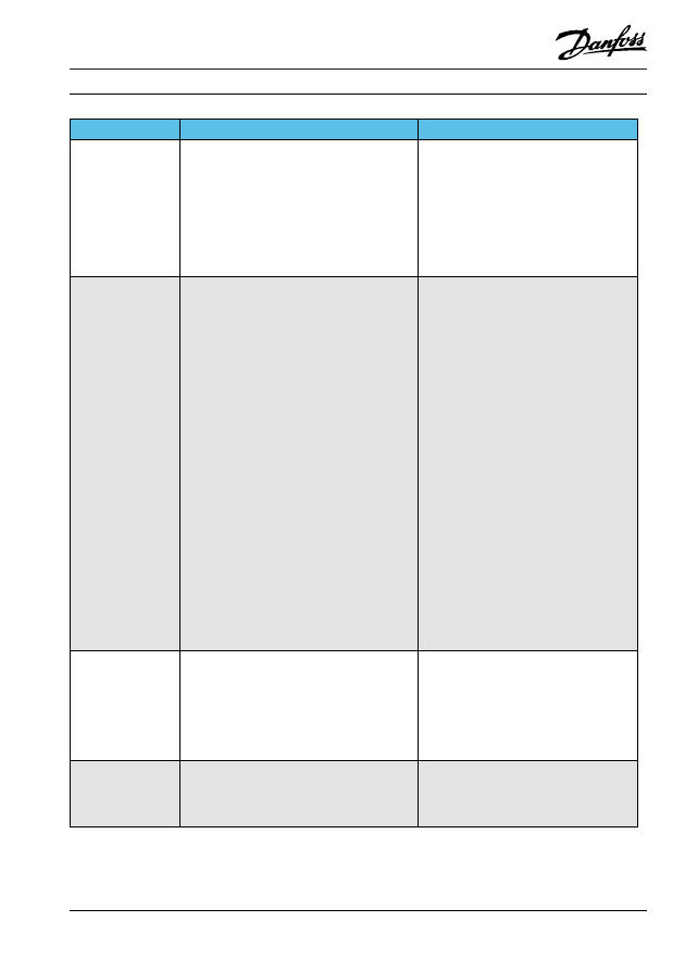
Compressors for refrigeration and air conditioning
These products include hermetic reciprocating compressors,
scroll compressors and fan-cooled condensing units. Typical
applications are air conditioning units, water chillers and
commercial refrigeration systems.
Wyszukiwarka
Podobne podstrony:
M DiPasquale ANABOLIC TROUBLESHOOTER GUIDE
Troubleshooting Guide
Compaq Troubleshooter Guide
M DiPasquale ANABOLIC TROUBLESHOOTER GUIDE
TROUBLESHOOTING GUIDE
A8Jn Troubleshooting Guide
Halley RF Troubleshooting and Maintenance Guide V1 0
Electrician's Troubleshooting and Testing Pocket Guide
Z1010 Trouble Shooting Guide
Trouble Shooting Guide 04
guide camino aragones pl
Herbs for Sports Performance, Energy and Recovery Guide to Optimal Sports Nutrition
Meezan Banks Guide to Islamic Banking
NLP for Beginners An Idiot Proof Guide to Neuro Linguistic Programming
freespan spec guide
Eaton VP 33 76 Ball Guide Unit Drawing
Herbs to Relieve Headaches Keats Good Herb Guide
50 Common Birds An Illistrated Guide to 50 of the Most Common North American Birds
więcej podobnych podstron