
Insulation Resistance 1000M
min (at 500VDC) Item 7 of IEC255-5
Dielectric Strength
Between contacts 50Hz 500V Item 6 of IEC255-5
Between contact and coil 50Hz 1000V Item 6 of IEC255-5
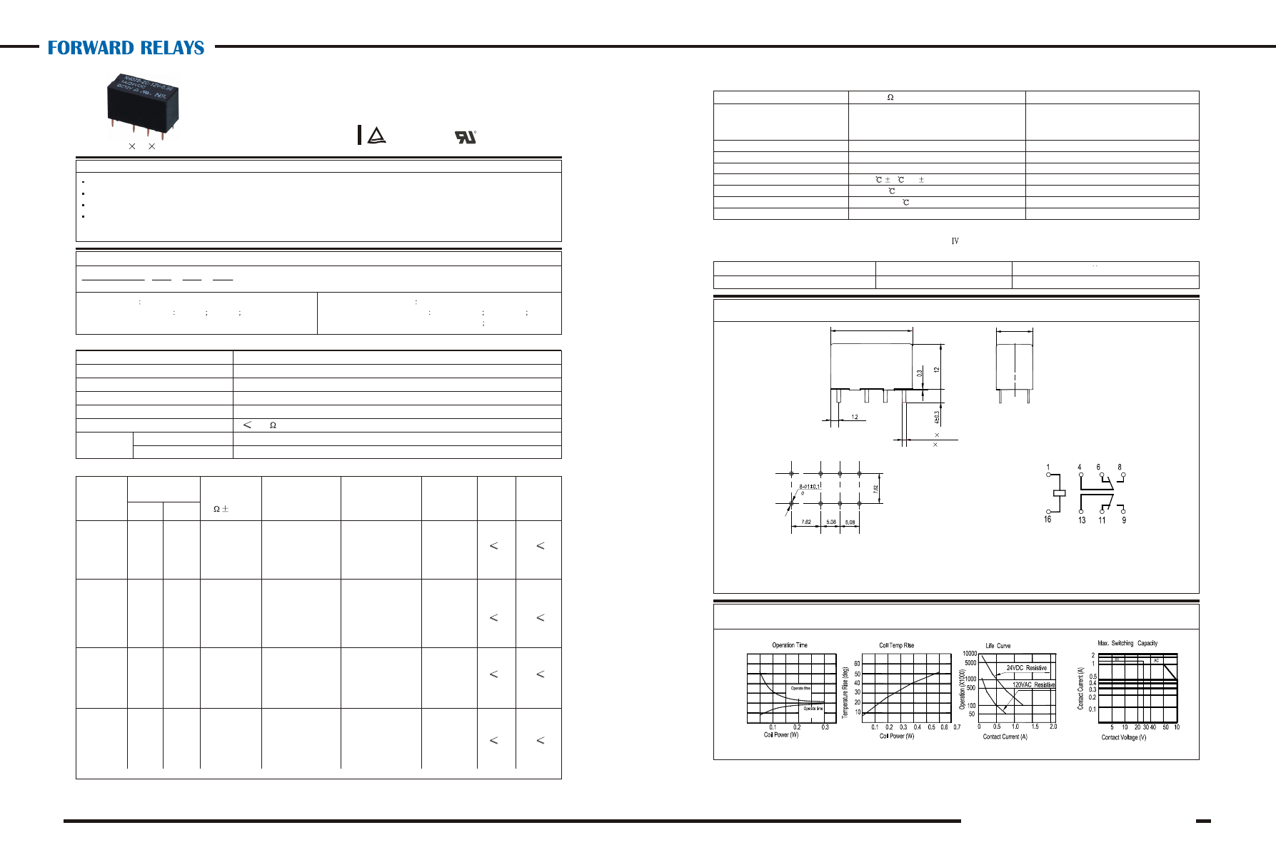
Dimensions
Qualification inspection:
Perform the qualification test as specified in the table
of IEC255-19-1 and minimum sample size 24.
NOTES 1).Dimensions are in millimeters.
2).Inch equivalents are given for general information only.
2
Shock resistance 5 00m/s 11ms IEC68-2-27 Test Ea
Vibration resistance 10~70Hz double amplitude 1.5mm IEC68-2-6 Test Fc
Terminals strength 5N IEC68-2-21 Test Ua1
Solderability 235
2
3
0.5s IEC68-2-20 Test Ta method 1
Ambient Temperature -30~70
Relative Humidity 85% (at 40
) IEC68-2-3Test Ca
Mass 5g
Reference Data
Safety approval UL & CUR T V
Load 2A/28VDC,1A/125VAC 1A/125VAC;24VDC
Dimensions
Wiring diagram
(Bottom view)
Mounting (Bottom view)
15
10
5
T
im
e
(m
s
e
c
)
54
JRC-19F (4078)
Operation condition
Safety approvals
U
8-0.6
0.3
Small size, light weight.
Low coil power consumption.
PC board mounting.
Suitable for household electrical appliances, automation system, electronic equipment, instrument, meter,
telecommunication facilities and remote control facilities.
JRC-19F 2C 3V 0.2
1 2 3 4
1 Part number
JRC-19F(4078)
2 Contact arrangement
2A:2A
2C:2C
Dash
numbers
Coil voltage
VDC
Coil
resistance
10%
Operate
Time
ms
Release
Time
ms
Contact Arrangement 2A (DPSTNO) 2C (DPDT (B-M))
Contact Material Ag,AgNi(Au clod)
Contact Rating (resistive) 2A/28VDC,0.5A,1A/125VAC,30VDC
Max. Switching Power 48W 60VA
Max. Switching Voltage 30VDC 220VAC Max.Switching Current:2A
Rated Max
Pick up voltage
VDC (max)
(70% of rated
voltage )
Release voltage
VDC (min)
(10% ofrated
voltage)
Coil power
consumption
W
3 Coil rated voltage(V)
DC:3,4.5,5,6,12,24,48,
4 Coil power consumption
0.15:0.15W
0.2:0.2W
0.36:0.36W
0.51:0.51W
CAUTION:
1.The use of any coil voltage less than the rated coil voltage will compromise the operation of the relay.
2.Pickup and release voltage are for test purposes only and are not to be used as design criteria.
0.15
6
5
R2133344
003-150 3
3.9 60 2.25 0.3
004-150 4.5
5.9 135 3.15 0.45
005-150 5
6.5 166.7 3.50 0.5
006-150 6
7.8 240 4.20 0.6
012-150 12
15.6 960 8.40 1.2
024-150 24
31.2 3840 18.0 2.4
003-200 3
3.9 45 2.25 0.3
004-200 4.5
5.9 101 3.15 0.45
005-200 5
6.5 125 3.50 0.5
006-200 6
7.8 180 4.20 0.6
012-200 12
15.6 720 8.40 1.2
024-200 24
31.2 2880 18.0 2.4
003-360 3
3.9 25 2.25 0.3
004-360 4.5
5.9 56 3.15 0.45
005-360 5
6.5 70 3.50 0.5
006-360 6
7.8 100 4.20 0.6
012-360 12
15.6 400 8.40 1.2
024-360 24
31.2 1600 18.0 2.4
003-510 3
3.9 17.6 2.25 0.3
004-510 4.5 5.9 39.7 3.15 0.45
005-510 5
6.5 49 3.50 0.5
006-510 6
7.8 70.6 4.20 0.6
012-510 12
15.6 282.4 8.40 1.2
024-510 24
31.2 1129.4 18.0 2.4
048-510 48
62.4 4517.6 36.0 4.8
0.20
6
5
0.36
6
5
0.51
6
5
JRC-19F (4078)
21
10
12
Features
Ordering Information
Contact Data
Contact Resistance or Voltage drop 50m
I tem 3
.12 o
f I EC255-7
5
Operational Electrical 10 Item 3.30 of IEC255-7
7
life Mechanical 10 Item 3.31 of IEC255-7
Coil Parameter
53
R
E158859
C
US
009-200 9
11.7 405
6.75
0.9
0.024
0.012
0.047
0.827
21max.
0.393
10max.
0
.0
1
2
0
.4
7
2
0
.0
1
2
0.300
0.200 0.200
0
.4
7
2
0.039
mm /inch
Ningbo Forward Relay Corporation LTD.
Insulation Resistance 1000M
min (at 500VDC) Item 7 of IEC255-5
Dielectric Strength
Between contacts 50Hz 500V Item 6 of IEC255-5
Between contact and coil 50Hz 1000V Item 6 of IEC255-5
Dimensions
Qualification inspection:
Perform the qualification test as specified in the table
of IEC255-19-1 and minimum sample size 24.
NOTES 1).Dimensions are in millimeters.
2).Inch equivalents are given for general information only.
2
Shock resistance 5 00m/s 11ms IEC68-2-27 Test Ea
Vibration resistance 10~70Hz double amplitude 1.5mm IEC68-2-6 Test Fc
Terminals strength 5N IEC68-2-21 Test Ua1
Solderability 235
2
3
0.5s IEC68-2-20 Test Ta method 1
Ambient Temperature -30~70
Relative Humidity 85% (at 40
) IEC68-2-3Test Ca
Mass 5g
Reference Data
Safety approval UL & CUR T V
Load 2A/28VDC,1A/125VAC 1A/125VAC;24VDC
Dimensions
Wiring diagram
(Bottom view)
Mounting (Bottom view)
15
10
5
T
im
e
(m
s
e
c
)
54
JRC-19F (4078)
Operation condition
Safety approvals
U
8-0.6
0.3
Small size, light weight.
Low coil power consumption.
PC board mounting.
Suitable for household electrical appliances, automation system, electronic equipment, instrument, meter,
telecommunication facilities and remote control facilities.
JRC-19F 2C 3V 0.2
1 2 3 4
1 Part number
JRC-19F(4078)
2 Contact arrangement
2A:2A
2C:2C
Dash
numbers
Coil voltage
VDC
Coil
resistance
10%
Operate
Time
ms
Release
Time
ms
Contact Arrangement 2A (DPSTNO) 2C (DPDT (B-M))
Contact Material Ag,AgNi(Au clod)
Contact Rating (resistive) 2A/28VDC,0.5A,1A/125VAC,30VDC
Max. Switching Power 48W 60VA
Max. Switching Voltage 30VDC 220VAC Max.Switching Current:2A
Rated Max
Pick up voltage
VDC (max)
(70% of rated
voltage )
Release voltage
VDC (min)
(10% ofrated
voltage)
Coil power
consumption
W
3 Coil rated voltage(V)
DC:3,4.5,5,6,12,24,48,
4 Coil power consumption
0.15:0.15W
0.2:0.2W
0.36:0.36W
0.51:0.51W
CAUTION:
1.The use of any coil voltage less than the rated coil voltage will compromise the operation of the relay.
2.Pickup and release voltage are for test purposes only and are not to be used as design criteria.
0.15
6
5
R2133344
003-150 3
3.9 60 2.25 0.3
004-150 4.5
5.9 135 3.15 0.45
005-150 5
6.5 166.7 3.50 0.5
006-150 6
7.8 240 4.20 0.6
012-150 12
15.6 960 8.40 1.2
024-150 24
31.2 3840 18.0 2.4
003-200 3
3.9 45 2.25 0.3
004-200 4.5
5.9 101 3.15 0.45
005-200 5
6.5 125 3.50 0.5
006-200 6
7.8 180 4.20 0.6
012-200 12
15.6 720 8.40 1.2
024-200 24
31.2 2880 18.0 2.4
003-360 3
3.9 25 2.25 0.3
004-360 4.5
5.9 56 3.15 0.45
005-360 5
6.5 70 3.50 0.5
006-360 6
7.8 100 4.20 0.6
012-360 12
15.6 400 8.40 1.2
024-360 24
31.2 1600 18.0 2.4
003-510 3
3.9 17.6 2.25 0.3
004-510 4.5 5.9 39.7 3.15 0.45
005-510 5
6.5 49 3.50 0.5
006-510 6
7.8 70.6 4.20 0.6
012-510 12
15.6 282.4 8.40 1.2
024-510 24
31.2 1129.4 18.0 2.4
048-510 48
62.4 4517.6 36.0 4.8
0.20
6
5
0.36
6
5
0.51
6
5
JRC-19F (4078)
21
10
12
Features
Ordering Information
Contact Data
Contact Resistance or Voltage drop 50m
I tem 3
.12 o
f I EC255-7
5
Operational Electrical 10 Item 3.30 of IEC255-7
7
life Mechanical 10 Item 3.31 of IEC255-7
Coil Parameter
53
R
E158859
C
US
009-200 9
11.7 405
6.75
0.9
0.024
0.012
0.047
0.827
21max.
0.393
10max.
0
.0
1
2
0
.4
7
2
0
.0
1
2
0.300
0.200 0.200
0
.4
7
2
0.039
mm /inch
Ningbo Forward Relay Corporation LTD.
Wyszukiwarka
Podobne podstrony:
Leki wplywajace na miesnie szkieletowe i przekaznict wo nerwowo
019 Masowe środki przekazu mass media
Co Krasnokutski przekazał na pokład tupolewa Nasz Dziennik
przekazywanieciepla19042009
karta przekazania odpadu WZÓR, Ochrona środowiska, ekologia przemyslowa, GR 7 c, Filtry olejowe 16
4078
INSTRUKCJA PRZEKAZYWANA BADANYM
przekąski ciepłe
Wykład; Przekaz nt zdrowia w USA
Przekaźniki
przekaĹĽnik kierunkowy
przekaz digitalny
Przekażnik RA2
jednostka przekazu danych dmu2000
Przekazniki czasowe id 404749 Nieznany
char czas przekaznikow
więcej podobnych podstron