Animating one car on a straight road is easy, but if you want to animate one or several cars
following a curve, with speed variations, and other refinements, you will need a method
allowing automatic steering and proportionnal speed for the wheels rotation.
This tutorial will show up how to make automated animations for cars.
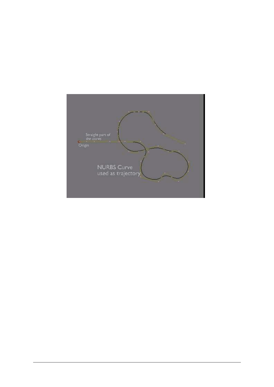
Your car trajectory will be a nurbs curve (
Fig. 1-2
).
A bezier curve could do the trick, but Nurbs curves are easier to manage with. I say a
trajectory instead of a path, because we will not use it as a real Path. Generally, a Path curve
has a speed Ipo, and plays the animation on a fixed number of frames. The method that I
want to show you, uses a more flexible way in my opinion.
Later, in your animation, you will need a car body. For now, it is not necessary, and you only
have to know that all car bodies you could model will be easily parented to the system that
we will build now.
You only need to model one wheel, and duplicate it four times. The front wheels will remain
free, and the rear wheels will be joined in one unique object.
It is important to put the center of each object exactly at the center of each mesh. So, each
front wheel will have it’s own center, and the rear wheels will have their center at half
distance between them.
The distance between the front and rear wheels is not too important right now, and it will be
adjustable later to the dimension of the car bodies that you will use.
You will need a Mesh that will be used as a Chassis to parent the wheels and the body. As
this object will not be rendered, you will set for it an unvisible material, or a bound box. You
could also use an empty or even a bone, but a flattened cube will be visually of a better help.
BLENDER TUTORIAL
- Automated animation for cars -
Blender tutorial written by Philippe ROUBAL. ©2006. www.3d-synthesis.com .
Page 1 of 24.
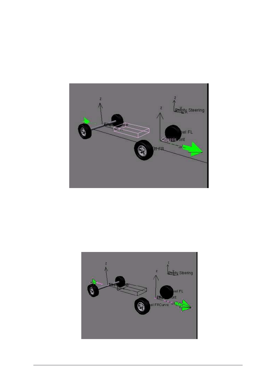
Fig. 3
shows the wheels and the Chassis object. The Chassis will not be rendered, and will
only be used for parenting parts like the wheels and the body. It can also be seen as a place
holder for the body during the animation setup.
Fig. 3
Before parenting things, you will have to be sure that all the object have their axis oriented in
the same direction, so apply CTRL-A to all of them. This is very important if you don’t want
to fight with rebel objects later !
An other mesh will be necessary. This one will also be unvisible at rendering, but is very
important for the animation. This mesh, that we’ll call Arrow mesh, because of its shape, will
be the core of the animation (
Fig. 4
).
You have to choose
a starting direction for your animation. In this example, I have choosen the X axis.
BLENDER TUTORIAL
- Automated animation for cars -
Blender tutorial written by Philippe ROUBAL. ©2006. www.3d-synthesis.com .
Page 2 of 24.

For the Arrow mesh, you can start with a single plane that you will duplicate to get a small
square face centered at half distance of the rear wheels, an other one at half distance of the
front wheels.
These two groups of vertices are the references for the animation. We’ll see later what they
are exactly used for.
You can add several other groups of vertices, that will be used as helpers for the animation.
The front end of this mesh will be an arrow head shape, and you can add a tail made of
several square faces. the Arrow mesh is shown in green color on
Fig. 4
.
As we might need to select the Arrow when the car body will be present, the head and the
tail of the Arrow mesh will be used to select easily the Arrow mesh when we’ll set up the
animation.
Now, we are going to add the curve, so add a Nurbs curve in top view, and draw the
trajectory of the car by adding as many dots as necessary.
In edit mode, select the first dot of the Nurbs curve, and by SHIFT-S, then Snap Cursor on
Selection. Make this location the center of the Curve Object. As Nurbs curve don’t extend
themselves until the extreme limits, you can add more dots close to the center of the Curve
object, to see the starting tip of the curve.
Your curve will have to be in straight line in the X direction (the direction choosen earlier),
in its starting part, in order to be able to set up correctly the rigging of the car parts (
Fig. 1-2
).
The easiest way to start drawing the curve is to resize it by 0 in Y direction to get the straight
part, and once you have set the first dot on the left as the center of the curve object, you
extrude the curve from the right side by selecting the dot and using CTRL-LMB.
Be sure that your curve and your arrow have their axis in the same direction by applying
CTRL-A.
Now, we have to link the arrow to the trajectory. Select the Arrow Mesh, and add a Curve
Modifier. Name it Curve, as it is the default name for the curve you have added.
Don’t be afraid, the Arrow will turn of 90°, and its center will get out of the arrow mesh and
will be displaced on the center of the curve. It is normal.
Now, rotate the Arrow of 90° to match the Curve direction. If you select the arrow, and move
it along the Y axis by G-Y, you will see your Arrow moving and bending along the curve.
Apply CTRL-A to your Arrow mesh again.
At first glance, it might be surprising to see that you have to move the Arrow mesh along the
Y axis to start a displacement in X direction, but from now, you must understand and keep in
mind that the straight displacement of the Arrow center along the Y axis represents the
displacements of the Arrow mesh along the curved trajectory. This is very important, because
you will be able to drive your car with only One Ipo curve (Loc X,in this example), and make
speed variations as well with this only curve (
Fig. 6
).
BLENDER TUTORIAL
- Automated animation for cars -
Blender tutorial written by Philippe ROUBAL. ©2006. www.3d-synthesis.com .
Page 3 of 24.
You can also notice that in Edit mode, the Arrow mesh is rotated. This is because you have
rotated the Mesh in object mode. As in Edit mode the Curve modifier is not applied, the mesh
appears rotated. This has no importance, and will not be a problem when you will have to
edit the mesh later.
Now, open an Ipo window. Select the Arrow mesh, and insert a Loc Key at frame one. Go to
Frame 100, or any Frame number matching the animation time you want, and move the
Arrow center along the Y axis, until the arrow mesh reaches the end of the curve. Then, insert
an other Loc Key. As only the Loc Y Ipo is interesting, you can delete the Loc X and Loc Z
Ipos.
You can set the Y Loc Ipo to linear or Bezier as you want. For the first settings, a linear curve
in suitable.
Troubles ? If you have done something wrong, you might notice that the axis direction of
your Arrow mesh is different than the axis direction of the Curve, and the animation now
doesn’t follow the curve. Instead, the Arrow moves along Y direction. If this appens to you, it
can be easily corrected either by applying CTRL-A to your Arrow mesh. You may also need
to play in the Ipo window, by replacing the Loc Y curve by the Loc X curve, using the buffer
(Buttons with yellow arrows).
If you want to rotate the scene of 90°, you have to rotate only the Curve around its center,
and apply CTRL-A to it, and everything will work correctly. Any other angles are also
usable. This said, it is safer to keep the original direction, if you can.
Go back to Frame 1.
Now we have to take care of the rigging of the car parts themselves.
We will need 3 Empties. (
Fig. 7
).
One is named
Empty Rear .
BLENDER TUTORIAL
- Automated animation for cars -
Blender tutorial written by Philippe ROUBAL. ©2006. www.3d-synthesis.com .
Page 4 of 24.
It will be the rear tracking reference for the Chassis. This Empty will be Vertex Parented to a
square face of the Arrow mesh, placed exactly between the rear wheels. This Empty will be
the warranty that the trajectory will pass exactly in the middle of the rear wheels. This Empty
will be animatable later with a dLoc offset value, if you want to add a skid effect on the rear
wheels.
The second Empty is named Empty Front. It is Vertex Parented to a square face of the Arrow
mesh placed exactly between the two front wheels, in the same way you parented the Empty
Rear.
The Chassis mesh has its center placed exactly on the Empty Front and is parented to it. This
allows it to rotate around this Empty.
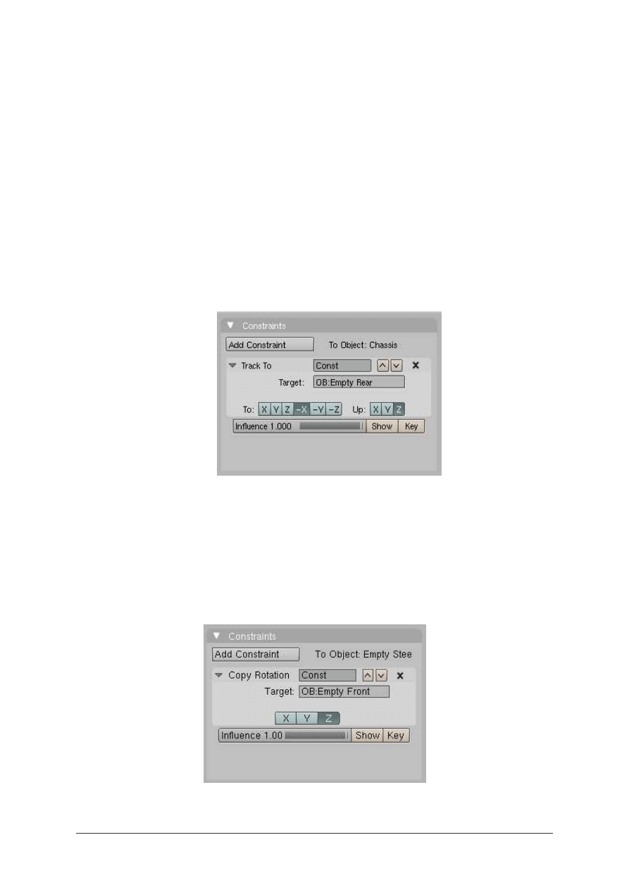
The chassis has a Track To constraint aiming the Empty named Empty Rear. (
Fig. 8
).
As the car body will be parented to this Chassis object, the car body will always be right on
the trajectory.
The third Empty is named Empty Steering. This empty will be used to copy the Z rotation of
the Empty named Empty Front, and to tranfer this rotation to the Front Left wheel. Empty
Steering will be parented to the Chassis. As said, it has a Copy Rotation Constraint, copying
the Z rotation of Empty Front. (
Fig. 9
).
BLENDER TUTORIAL
- Automated animation for cars -
Blender tutorial written by Philippe ROUBAL. ©2006. www.3d-synthesis.com .
Page 5 of 24.
The Rear wheels and the Front Right wheel are also parented to the Chassis.
The Front Left wheel is parented to Empty Steering.
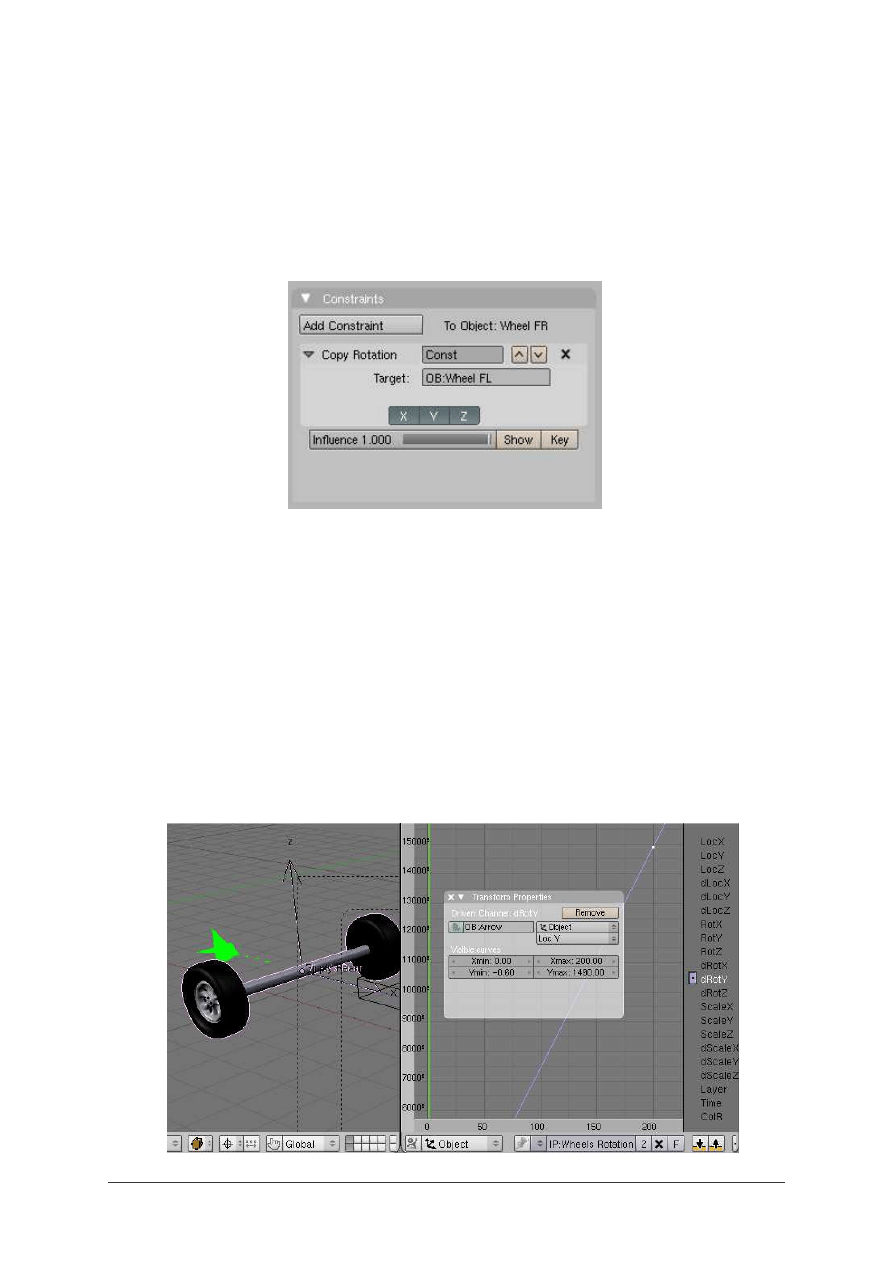
The Front Right wheel has a Copy Rotation Constraint. It copies the rotation of all axis of the
Front Left Wheel. (
Fig. 10
).
We have got our steering control.
Now, we are going to make our wheels rotate at a proportionnal speed, accordingly to the
speed of the car along its trajectory.
This function involves to set a proportionnal ratio between the rotation and translation
movement. First, we have to give a rotation speed to the wheels. We’ll adjust the ratio later.
Select the rear wheels. Open an Ipo window. If you have done everything like in the
example, the rotation axis of the wheels is the Y axis. So, insert a dRot Y key (we use a
relative key) at Frame 0. (
Fig. 11
).
Insert
an
BLENDER TUTORIAL
- Automated animation for cars -
Blender tutorial written by Philippe ROUBAL. ©2006. www.3d-synthesis.com .
Page 6 of 24.
other Ipo key at Frame 200, for example. Set the curve to Linear, and select Extrapolation
mode.
Add a driver to this Ipo. In the Driver Object field, type the name of the Driver. This name is
Arrow, because the rotation speed will depend of the speed of the Arrow object along its
trajectory.
Select LocY in the Driver Channel.
The slope of this Ipo curve will define the Factor (ratio) used to moderate the rotation speed.
This will be adjusted for the diameter of the wheels, by moving vertically the second dot of
the dRotY Ipo curve (the dot set at Frame 200).
So, now we have to set the slope of the dRotY Ipo curve.
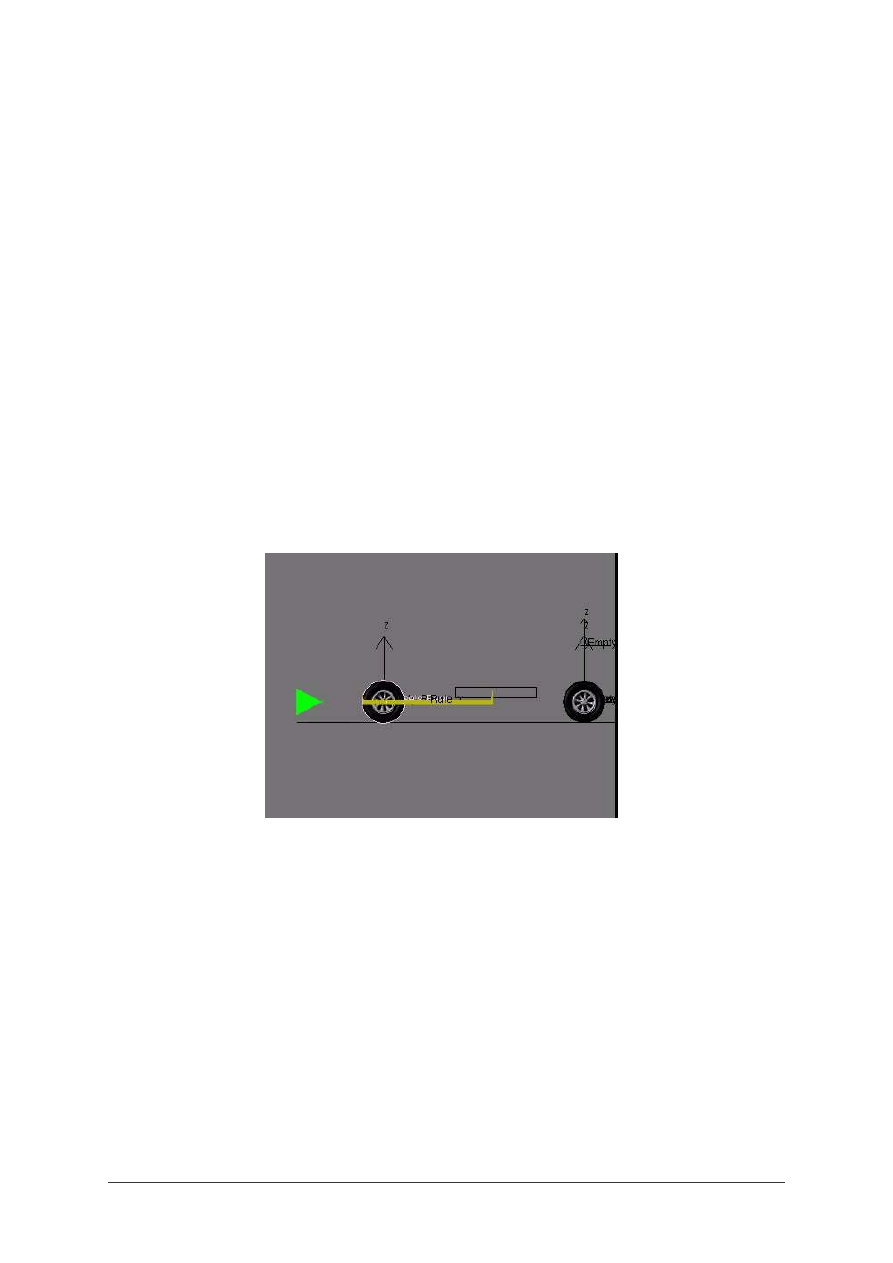
In side view, add a plane to create a strip named Rule. The width of this Rule must be
adjusted in Edit Mode to match the diameter of the Rear wheels. When this rule is made,
resize it by a factor of 3.14 in object mode using the Transform Pannel. The new size of the
rule gives the course for each wheel turn. (
Fig. 12
).
We must set the speed of the Arrow on the trajectory in order to have an entire number of
frames for a course equal to the length of the Rule.
The Rule is set at Frame 1 to be at the position of the Rear wheels.
In our example, we have choosen a number of 11 Frames. So, now the Timeline Cursor is set
to Frame 12.
By adjusting the LocY coordinate of the dot at Frame 200 in the Arrow Ipo window, we
adjust the position of the Rear wheels for a course equal to the length of the Rule.
For this given number of Frames, the wheels have to be in the same position as they were at
frame 1.
BLENDER TUTORIAL
- Automated animation for cars -
Blender tutorial written by Philippe ROUBAL. ©2006. www.3d-synthesis.com .
Page 7 of 24.
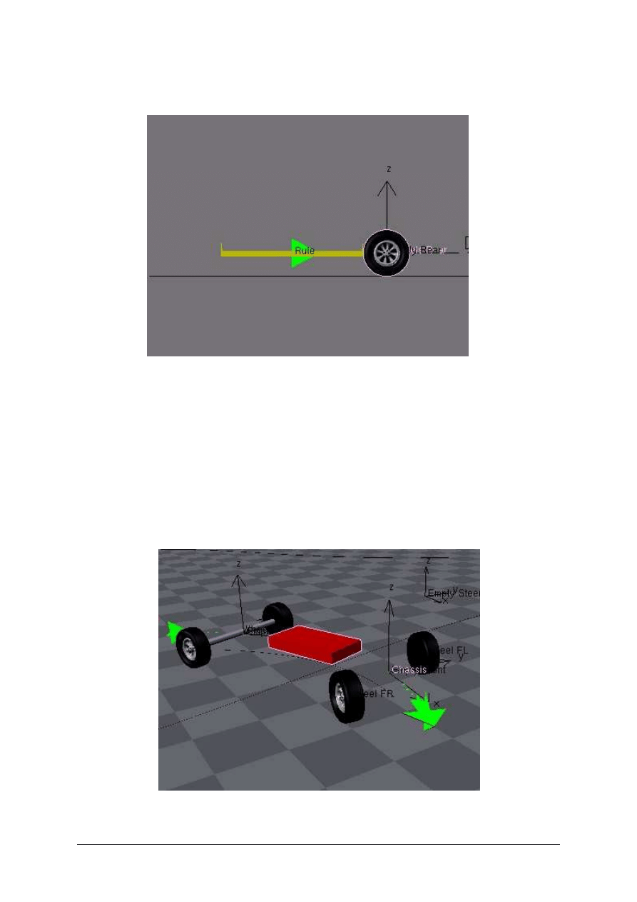
Fig. 13
So, now we have to play with the Rotation Ipo curve of the wheels.
By adjusting the dRotY value of the dot at Frame 200, you will set the rotation angle of the
wheel at Frame 12 equal to the angle at Frame 1.
Now, the rotation and translation speed are perfectly proportionnal. You can modify the
speed of the Arrow mesh, and the wheels rotation will always match the linear speed.
Fig. 14
Fig. 15
BLENDER TUTORIAL
- Automated animation for cars -
Blender tutorial written by Philippe ROUBAL. ©2006. www.3d-synthesis.com .
Page 8 of 24.
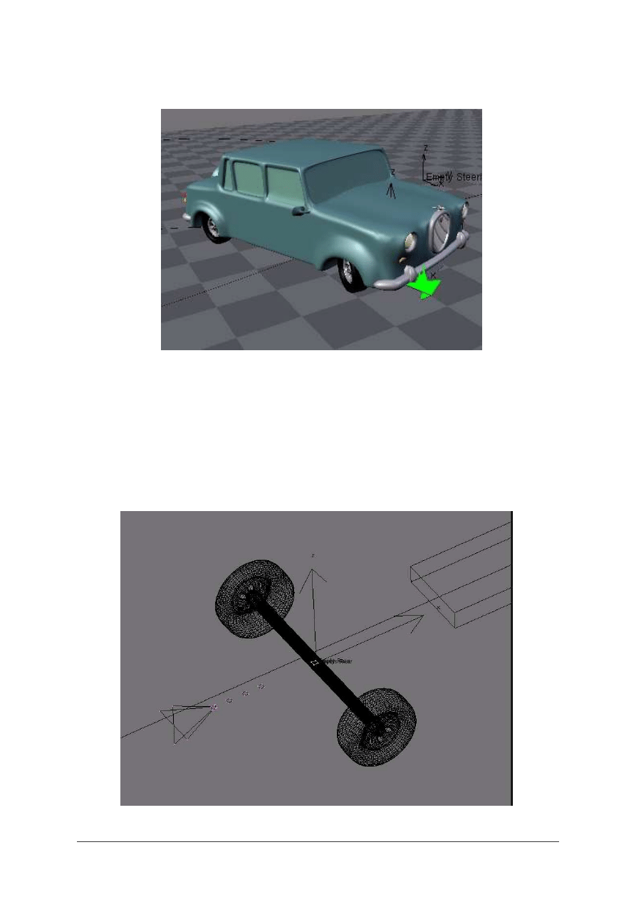
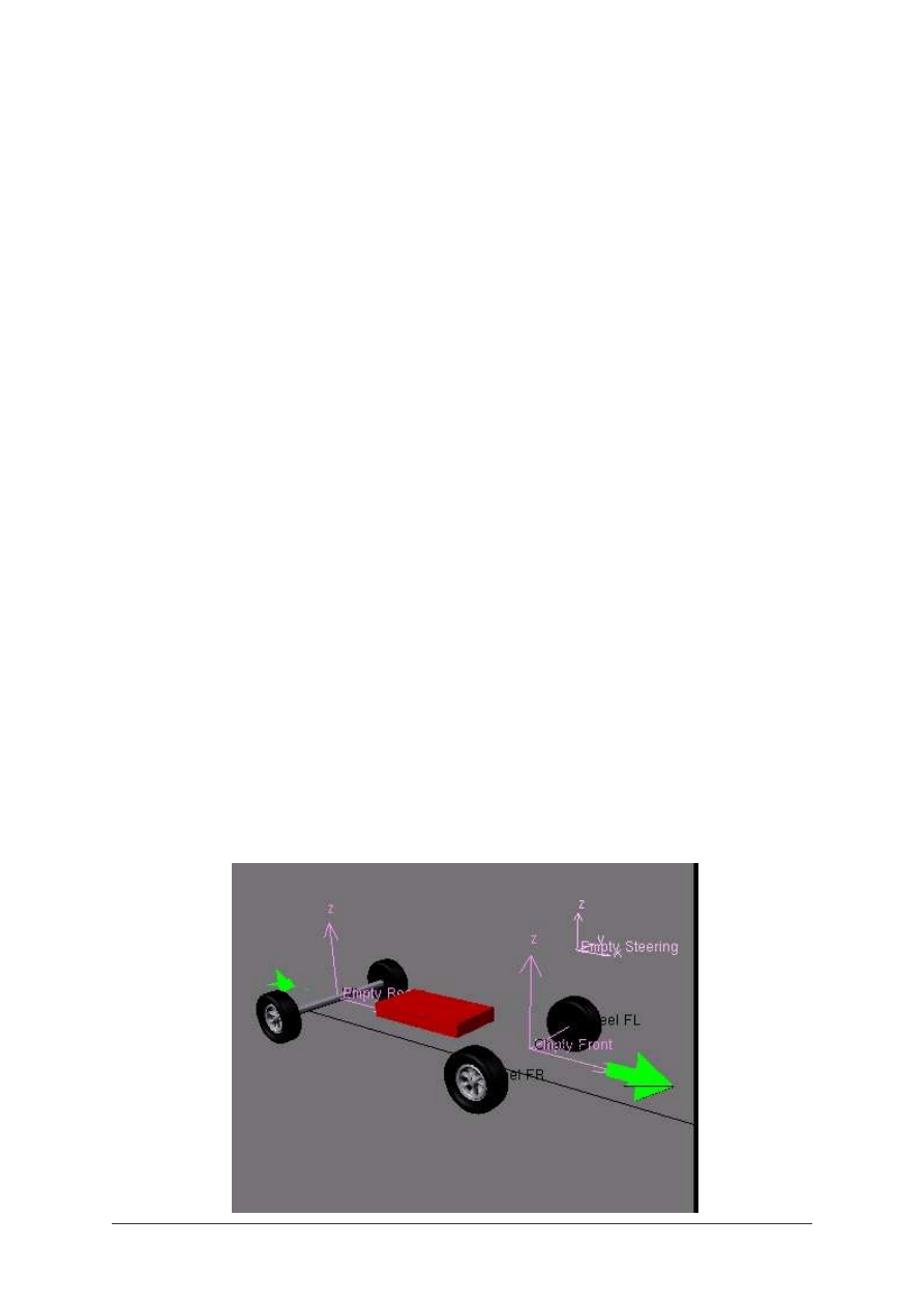
Now, you can add the car body that you have modelled.
You may have to adjust the position of the rear wheels. Obviously, you can move freely the
rear wheels, but you also have to edit the position of the Vertices of the Arrow Mesh
supporting the Empty Rear, to be sure that the rear of the car will be centered on the
trajectory. This is done in Edit Mode :
Fig. 16
BLENDER TUTORIAL
- Automated animation for cars -
Blender tutorial written by Philippe ROUBAL. ©2006. www.3d-synthesis.com .
Page 9 of 24.
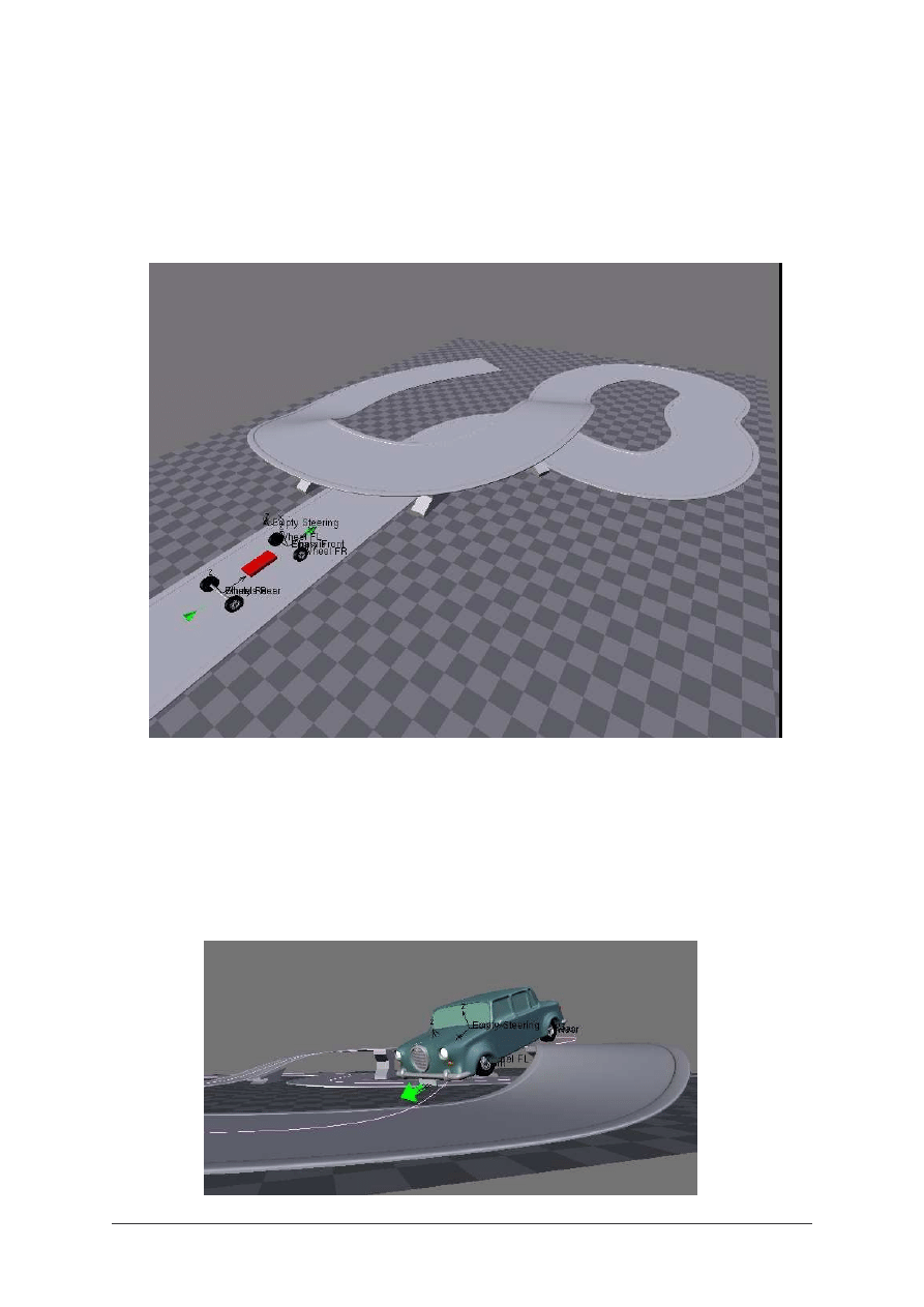
You can use the trajectory curve as an extrusion path for the road. You just have to draw a
profile with a NURBS curve, and use it as a Bevel Object for the trajectory curve.
The curve will have to be set to 3D.
Fig. 16
In order to get a better control on your car, you can duplicate the Curve and use the
duplicated curve for the extrusion of the road profile.
This way, you will be able to edit the trajectory and the road separately. this will allow you
more effects in your animation, like jumping :
Fig. 17
BLENDER TUTORIAL
- Automated animation for cars -
Blender tutorial written by Philippe ROUBAL. ©2006. www.3d-synthesis.com .
Page 10 of 24.
Now, our car can be driven automatically. The only thing we have to do is to edit the Ipo
Curve and the trajectory, for the good speed and path.
It is automated, but not very realistic. To add more realism to the animation, we have to
simulate the anticipation of the curves and add some slope to the body in the narrow curves.
Fig. 18
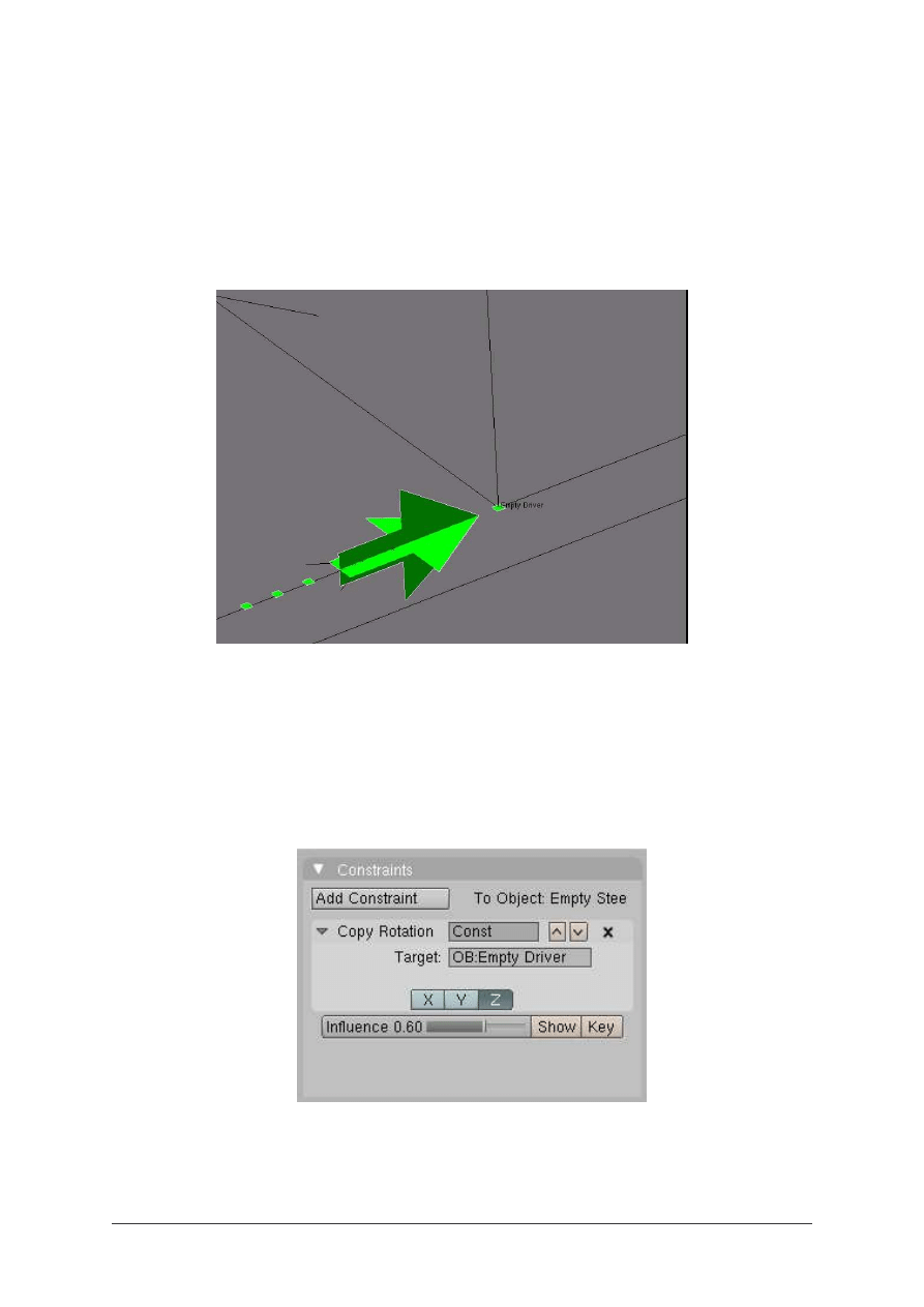
The anticipation of the curves will be achieved by using an other Empty, named Empty
Driver. This Empty is Vertex Parented to a new group of 4 vertice that we will create on the
front part of the Arrow mesh. This group will be affected sooner by the curve deformation.
So, if now we use this Empty Driver as the reference for the Copy Rotation constraint applied
to the Empty Steering, the wheels will turn sooner, and we’ll get our anticipation effect.
Fig. 19
The Anticipation effect can be adjusted by displacing the Vertices group along the X axis,
and the amplitude of the wheels rotation by the Influence factor of the Copy Rotation
constraint.
BLENDER TUTORIAL
- Automated animation for cars -
Blender tutorial written by Philippe ROUBAL. ©2006. www.3d-synthesis.com .
Page 11 of 24.
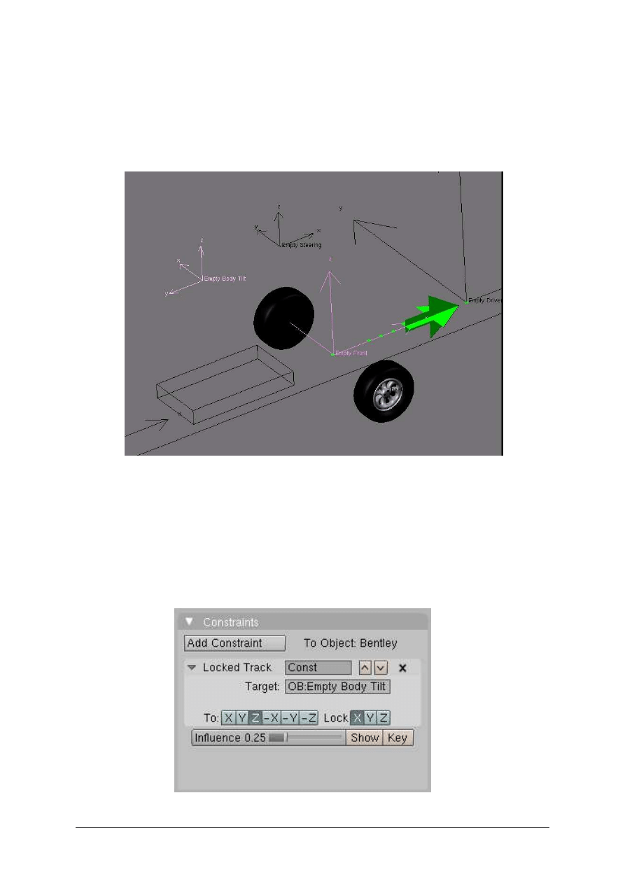
Now, we have to add the body tilt feature to our animation. This is done by adding one more
empty, right over the center of the car body. This Empty will be named Empty Body Tilt.
Fig. 20
The Empty Body Tilt will be parented to the Empty Front. So, when the Empty Front rotates
in the curves, the Empty Body Tilt will move from a side of the trajectory, to the other side.
Now, apply a Locked Track Contraint to the car body, aiming the Empty Body Tilt.
Fig. 21
BLENDER TUTORIAL
- Automated animation for cars -
Blender tutorial written by Philippe ROUBAL. ©2006. www.3d-synthesis.com .
Page 12 of 24.
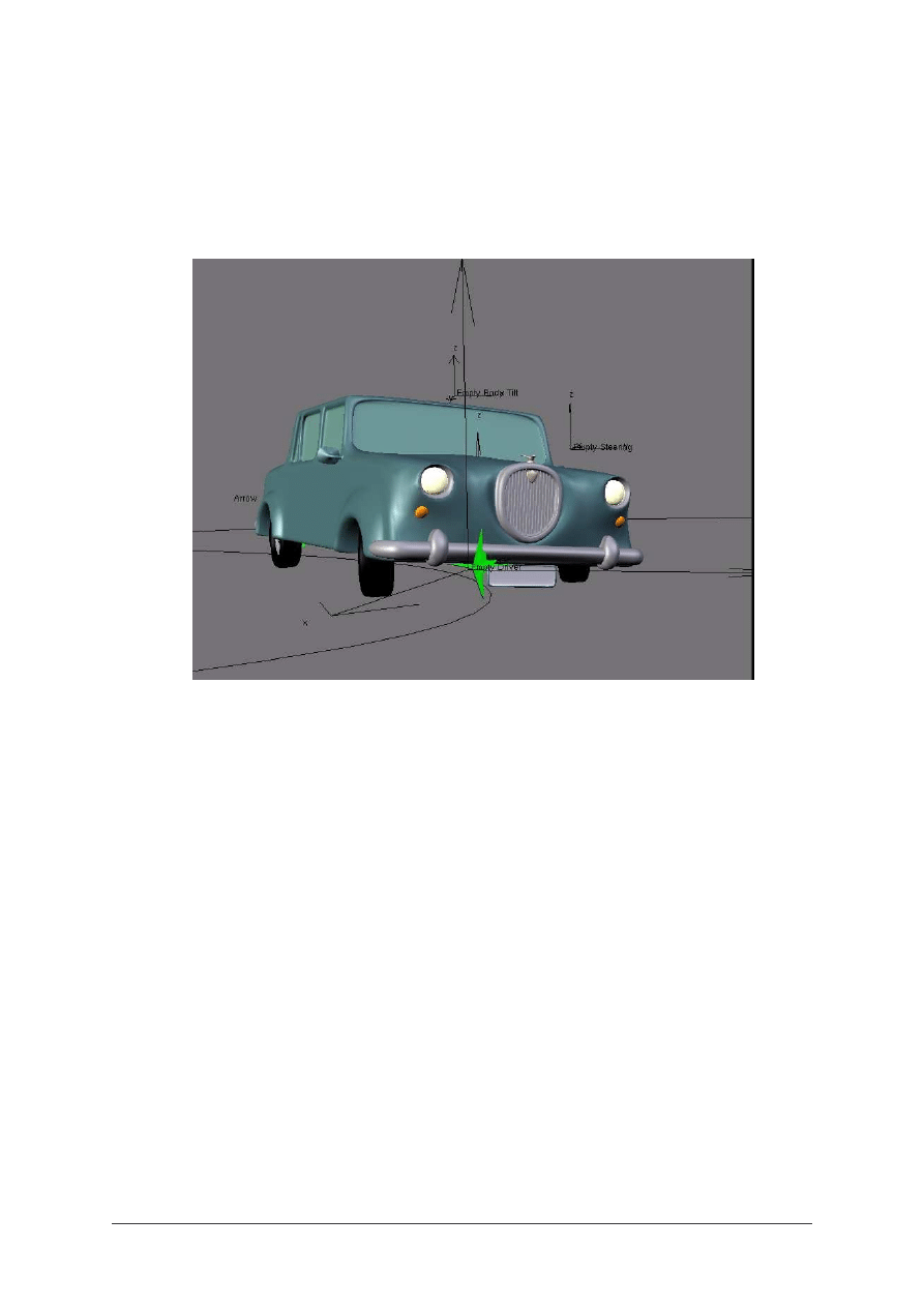
As the Empty Front is affected by the curve after the Empty Driver, the Body will follow the
movement of the wheels with a slight delay, which will add to the realism.
Fig. 22
Now, you should be able to make realistic cars animations, almost without entering keys by
hand, except for speed variations!
We can go further in the realism by animating the slope of the front wheels in the curve, and
simulating the compression of the tires in the area which is in touch with the ground.
The front wheels are mounted on ball and socket joints. So, because of the weight of the car
and the centrifugal force, the wheels don’t stay vertical in the curves.
For the setup of the wheels slope animation, we will need some more Empties and
constraints.
We have also to change some hiearchical relations between the objects.
As later in the tutorial we’ll have to deform only the tires, we can separate the tires from the
wheels.
Make a new large cylindrical object for front Axle, and use the Chassis as a parent for it.
Real cars have all their wheels joined to the Axle by ball bearings, and also ball and socket
joints for the front wheels only. We are going to simulate the ball bearings and the joints by
the use of Empties.
BLENDER TUTORIAL
- Automated animation for cars -
Blender tutorial written by Philippe ROUBAL. ©2006. www.3d-synthesis.com .
Page 13 of 24.
The front left joint will be simulated by the Empty Steering. Empty Steering will be now
parented to the front Axle instead of the Chassis.
Fig. 23
The front left wheel will be parented to Empty Steering, as previously.
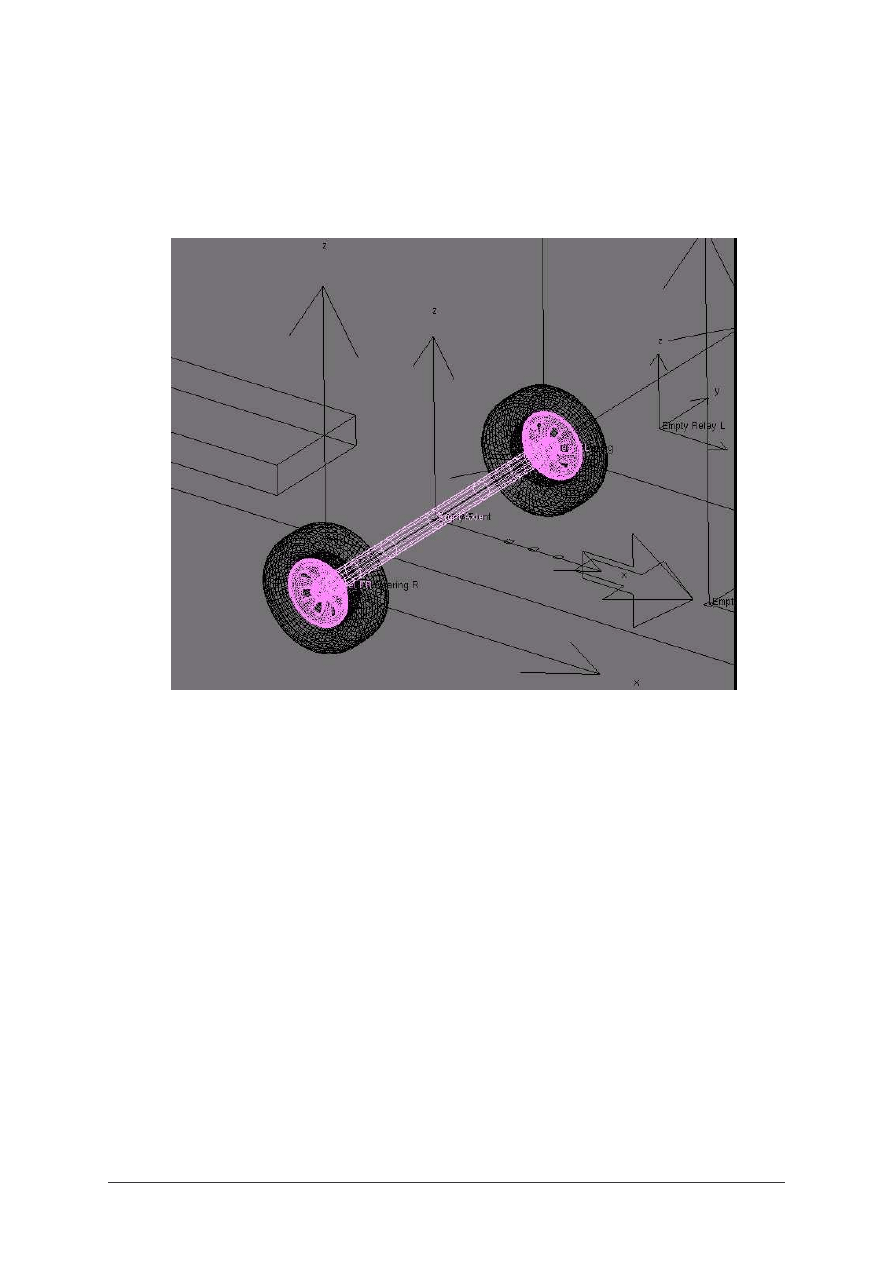
A new Empty, named Empty Ball Bearing R will be created at the opposite side of the axle,
and will be also parented to the axle. Empty Ball Bearing R will be the parent of the front
right wheel.
In the same way that the front right wheel copies the rotation of the front left wheel, Empty
Ball Bearing R will have a Copy Rotation Constraint copying the rotation of Empty Steering.
Now, we have to apply the slope variation to Empty Steering. This will be done by using as
reference the rotation of the Empty Driver.
We’ll want to adjuste the slope of the Wheels, so we can’t use directly the Empty Driver. We
have to add a new Empty, named Empty Relay. This empty will be parented to the Chassis,
and will use a Copy Rotation Constraint on Empty Driver, using only the Z axis of Empty
Driver. By adjusting the influence factor of the Copy Rotation Constraint, we will adjust the
rotation angle of Empty Relay, and the slope of the wheels.
At the tip of Empty Steering, add a new Empty named Empty L. This Empty will be parented
to Empty Relay,and will be used as a target for a Locked Track Constraint applied on the
BLENDER TUTORIAL
- Automated animation for cars -
Blender tutorial written by Philippe ROUBAL. ©2006. www.3d-synthesis.com .
Page 14 of 24.
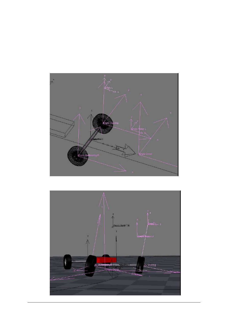
Empty Steering. This Constraint will be locked on the X axis, which is the rotation axis for
the slope of the wheels. The direction of the constraint will be the Z axis, which is the
direction of the vertical axis of Empty L.
Now, Empty Steering will aim the Empty L and will incline in the curves. As Empty Ball
Bearing R copies the rotation of Empty Steering, the two front wheels will have the same
slope.
Fig. 24
Fig. 25
BLENDER TUTORIAL
- Automated animation for cars -
Blender tutorial written by Philippe ROUBAL. ©2006. www.3d-synthesis.com .
Page 15 of 24.
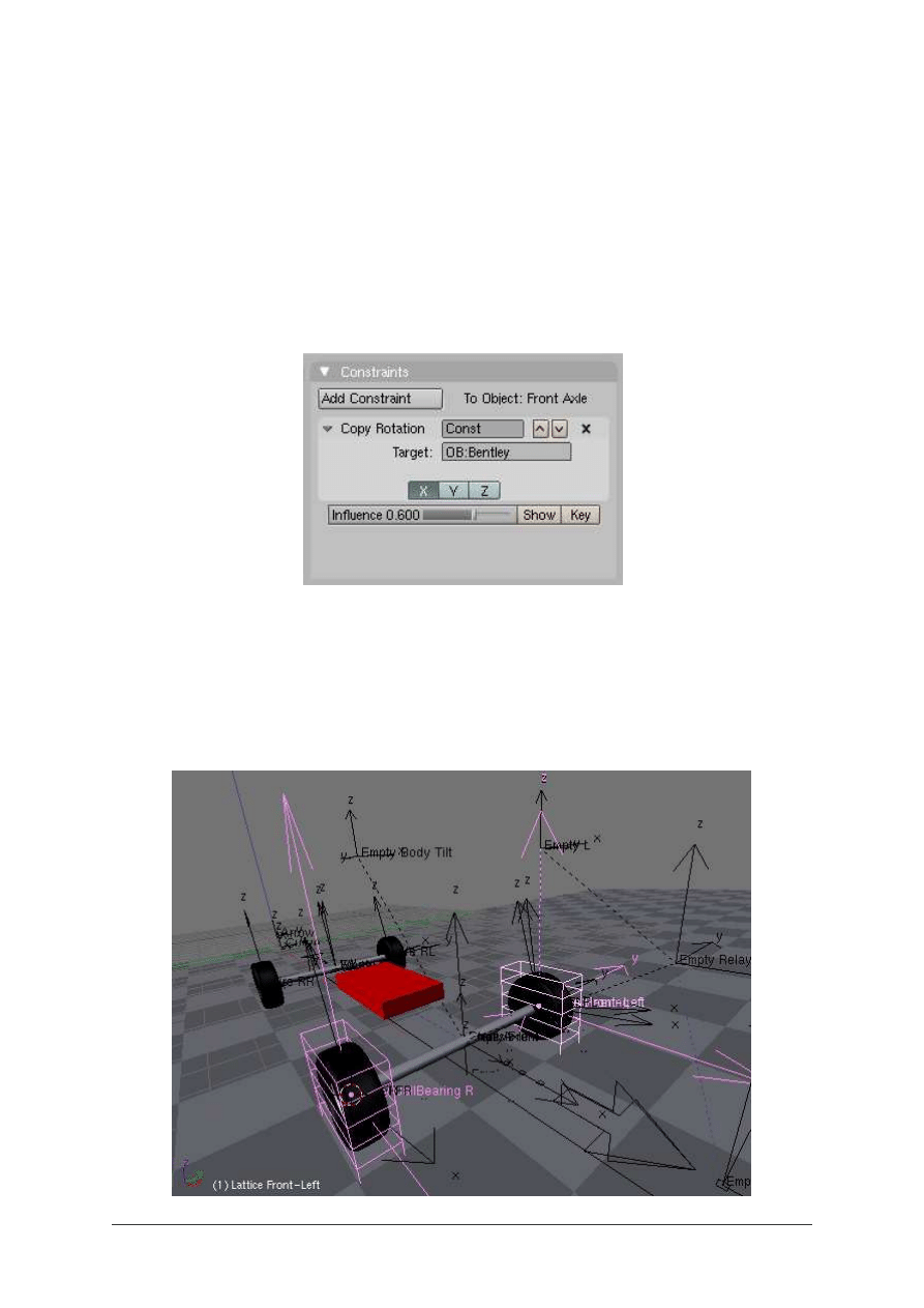
The next step will be the animation of the tires deformation. The axles of a car are not always
horizontal. They are linked to the car body by the suspension and the shock absorbers. They
follow the movement of the car’s body with a slight delay and a reduced amplitude.
We will reproduce this behaviour by adding to the front axle a Copy Rotation Constraint
using the X axis of the body of the car as reference. In the example file, the car body is
named Bentley.
Fig. 26
Now, has the front axle is no longer horizontal in the curves, it is necessary to simulate the
compression of the tires to avoid them passing through the floor. For this simulation, we’ll
add a Lattice to each front wheel. The lattices will be centered on the wheels centers. These
centers are also the centers of Empty Steering and Empty Ball Bearing R.
Fig. 27
BLENDER TUTORIAL
- Automated animation for cars -
Blender tutorial written by Philippe ROUBAL. ©2006. www.3d-synthesis.com .
Page 16 of 24.
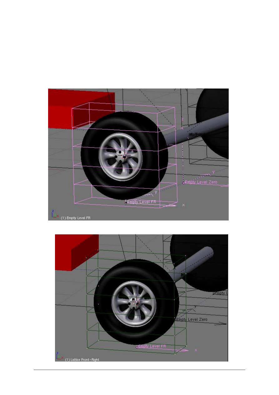
The Lattices will have to follow the slope of the wheels, so they are parented to Empty
Steering and Empty Ball Bearing R.
As we need to deform only the part of the tires between the wheel and the surface of the
ground, the Lattices will be divided in 5 cells.
Fig. 28
Fig. 29
BLENDER TUTORIAL
- Automated animation for cars -
Blender tutorial written by Philippe ROUBAL. ©2006. www.3d-synthesis.com .
Page 17 of 24.
We will animate only the lowest row of the lowest cell of Lattice Front-Right, by adding a
Hook to the Lattice. This Hook will be named Empty Level FR, for the Front Right wheel.
We’ll have an other Empty named Empty Level FL for the Front Left Wheel, applied on
Lattice Front-Left. Empty Level FR is parented to Empty Ball bearing R, and Empty Level
FL is parented to Empty Steering, so until now, they do not yet deform the lattices, but only
move with them.
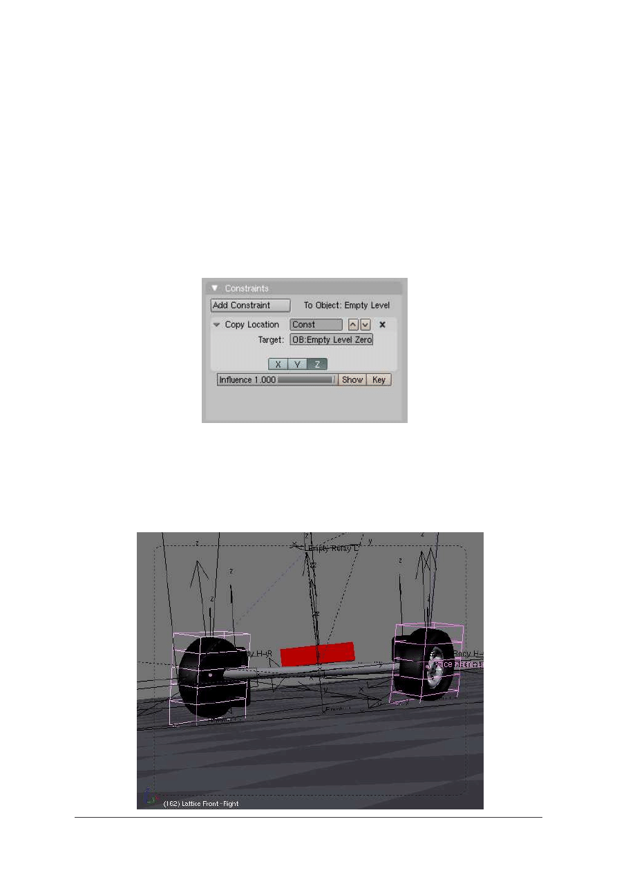
An Empty named Empty Level Zero is created and is parented to the Chassis.
The two Empties Empty Level FR and Empty Level FL are given each a Copy Location
Constraint copying the Z position of Empty Level Zero which is set at the level of the
ground.
Fig. 30
The two front tires now are deformed in the curves, but you may notice that the area of the
tires in contact with the ground is not horizontal, and that the inner side and outer side of the
tires passes through the ground plane in the curves.
Fig. 31
BLENDER TUTORIAL
- Automated animation for cars -
Blender tutorial written by Philippe ROUBAL. ©2006. www.3d-synthesis.com .
Page 18 of 24.
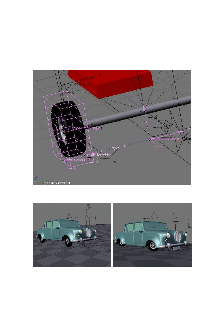
The reason why is that we have only used one Empty for the deformation of each lattice. If
you don’t plan to make camera takes in close up, this kind of animation could be sufficient.
Though, if needed, this can be easily corrected by adding one more empty to each Lattice.
Using two Empties per Lattice we’ll be able to keep the inside of the tires, as well as the
outside, in touch with the surface of the road.
Fig. 32
Fig. 33-34
You can see the effects of the system on these two images.
BLENDER TUTORIAL
- Automated animation for cars -
Blender tutorial written by Philippe ROUBAL. ©2006. www.3d-synthesis.com .
Page 19 of 24.
As the rear wheels have no steering and a rigid axle, they are easier to animate. For the slope
of the rear Axle, you can use the same system as described for the front wheels. Because
there is less weight on the rear wheels (the motor is in the front part of the car), the slope of
the axle will be of a lower amplitude (adjusted by an X Copy Rotation Constraint on the
body).
The slope of the rear axle will be less important, so the tires deformation will also be less
noticeable than for the front wheels. You can use only one Empty (Hook) on each Lattice.
If you don’t show the rear wheels in close up, you can even not use Lattices at all.
Now, you have a complete system for your car animation. It is convenient for a chase
animation, but we could add more life in our animation by animating the car driver.
Character animation is in my humble opinion the most difficult task. As I have few
experience in this domain, I always search systems to reduce the difficulties.
You can model a Steering-Wheel, and add it to your car model. This Steering-Wheel will
have its Z axis as rotation axis, and will be parented to the car body (not to the Chassis !).
The idea is to use the rotation of the Empty driver to put the Steering-Whell in rotation. If
you have already played with Copy Rotation Constraints, you might have noticed that it is
not possible to copy rotations between objects having their rotation axis oriented in a
different way. So, we’ll use an other method. This method will use the Locked Track
Constraint. It will be very useful when we’ll play with motorcycles, because of the slope of
the front wheel fork.
Let us come back to our animation.
Fig. 35
BLENDER TUTORIAL
- Automated animation for cars -
Blender tutorial written by Philippe ROUBAL. ©2006. www.3d-synthesis.com .
Page 20 of 24.
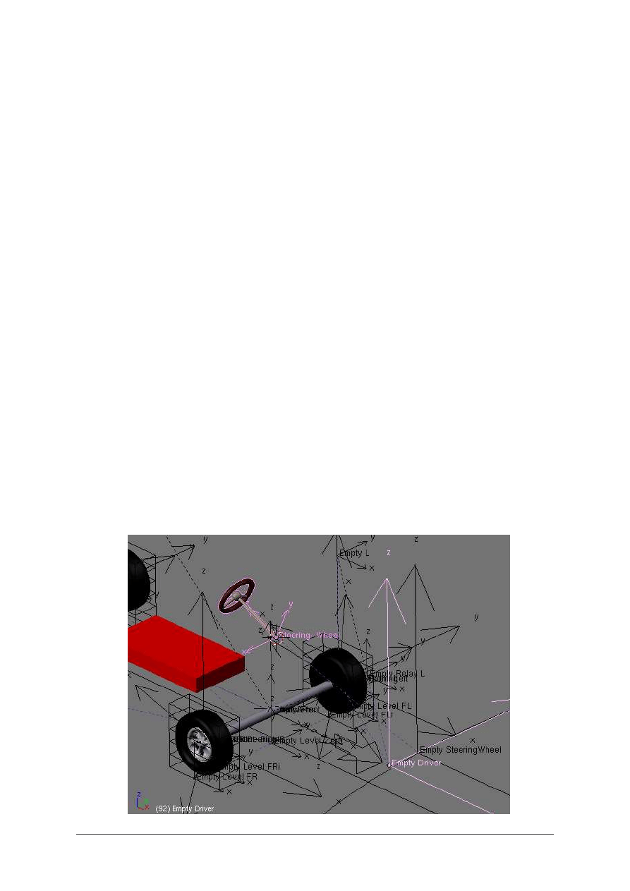
If we use the Empty Driver as target for the Locked Track Constraint, we’ll notice that the
rotation of the Steering-Wheel will not be symetrical. This is due to the fact that the Empty
Driver is not aligned with the Steering Wheel axis.
This small problem can be convoluted by adding a new Empty named Empty SteeringWheel,
which is aligned to the Steering-Wheel axis and parented to the Empty Steering.
Fig. 36
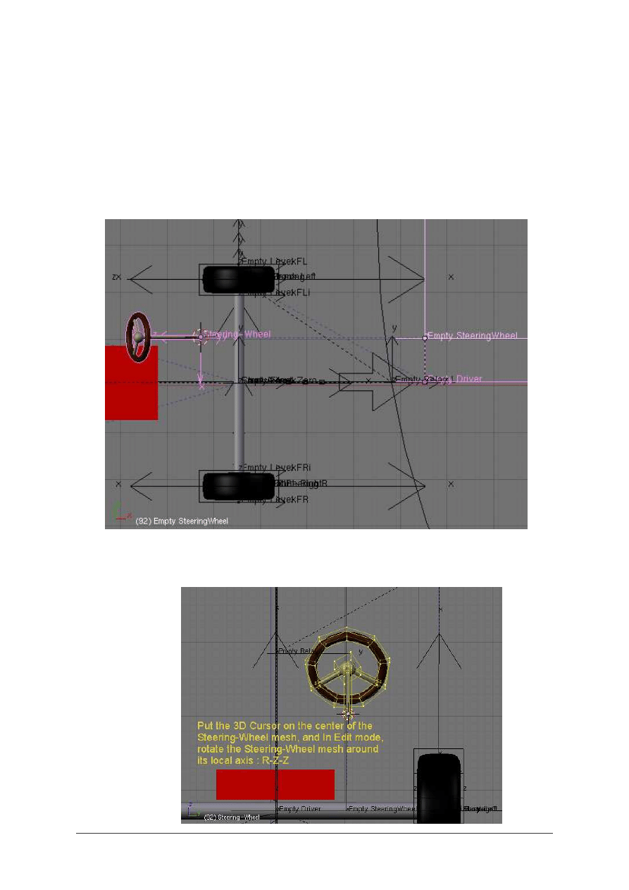
In straight line, the Steering-Wheel might make an unwanted angle. This can be easily
corrected in Edit mode, by rotating the mesh of the Steering-Wheel around its local Z axis, as
shown on
Fig. 37
.
R-Z-Z
BLENDER TUTORIAL
- Automated animation for cars -
Blender tutorial written by Philippe ROUBAL. ©2006. www.3d-synthesis.com .
Page 21 of 24.
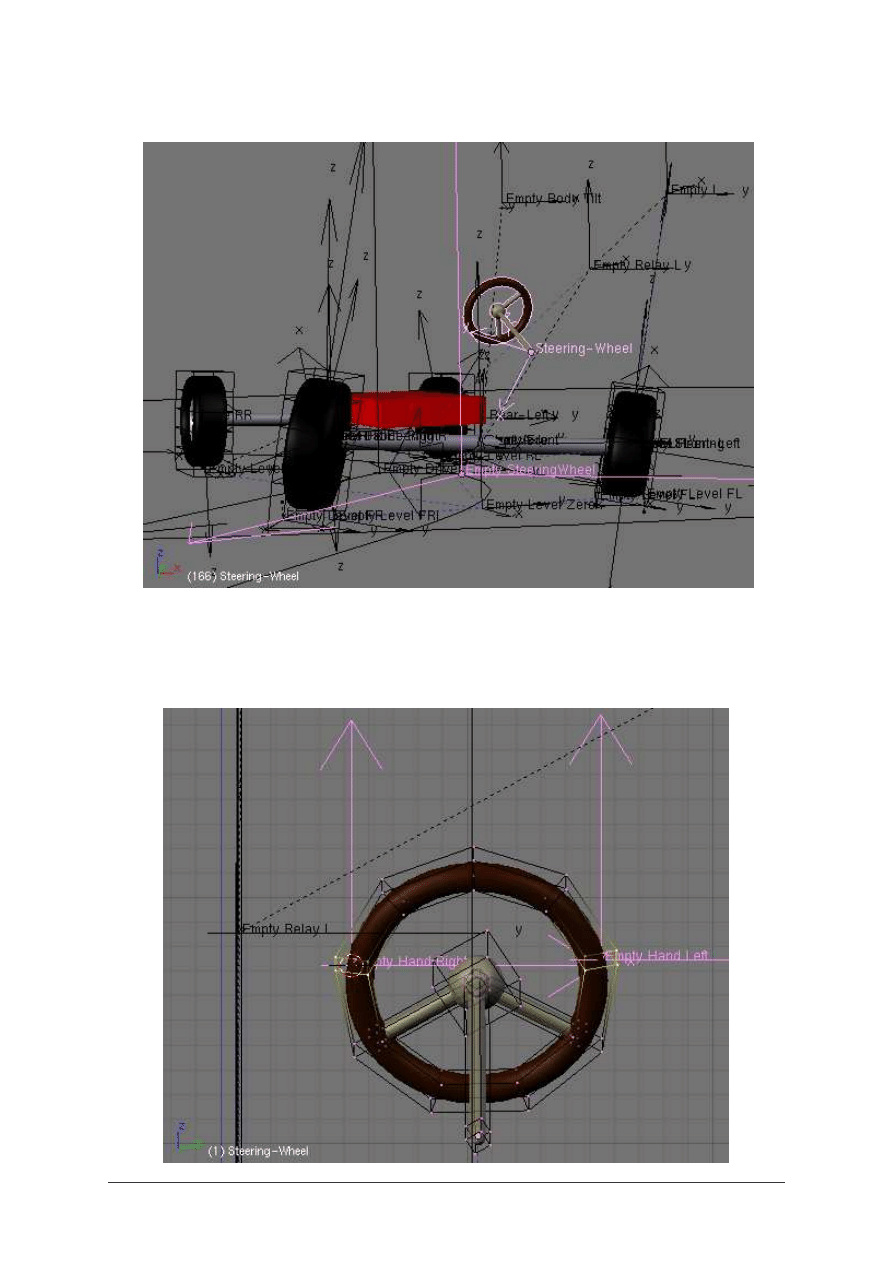
Fig. 38
The next step is easy to imagine. For the animation of your character, you will add two new
Empties which will be parented to the Steering-Wheel mesh using Vertex Parenting.
Fig. 39
BLENDER TUTORIAL
- Automated animation for cars -
Blender tutorial written by Philippe ROUBAL. ©2006. www.3d-synthesis.com .
Page 22 of 24.
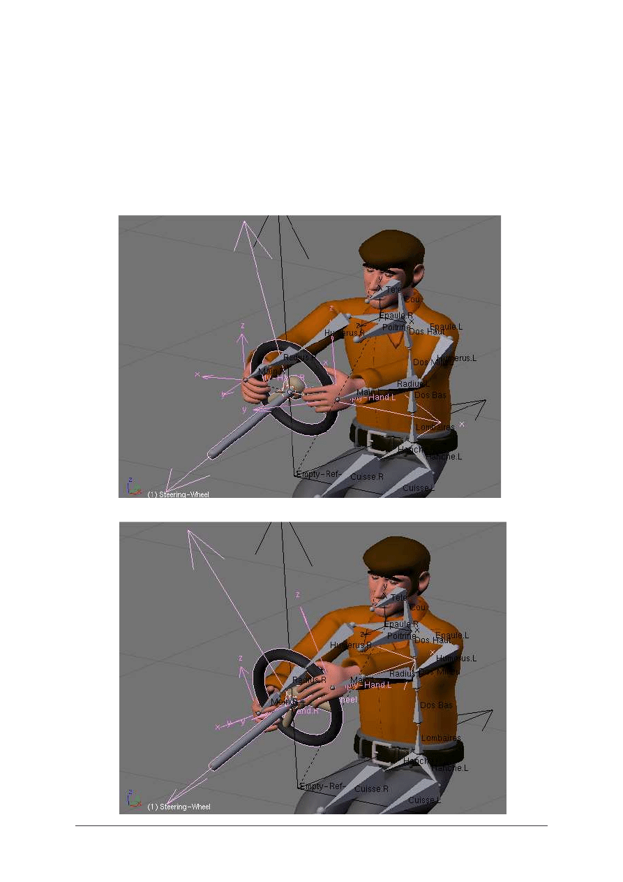
These two Empties will be used as targets to parent the IK Solvers of the driver character
hands. This way, the character will seem to drive the car in a realistic way. Though, there is a
noticeable difference with the real world, because in our 3D CG world, the car is driving the
character !
You can add more realism by using a track constraint or a copy rotation constraint applied to
the head bone of your character to make your driver look in the direction of the curves while
driving.
Fig. 40
Fig. 41
BLENDER TUTORIAL
- Automated animation for cars -
Blender tutorial written by Philippe ROUBAL. ©2006. www.3d-synthesis.com .
Page 23 of 24.

I hope that this tutorial has been understandable. If I have some time, I will make an other
one for the animation of motorcycles.
Vehicles with two wheels may seem more difficult to animate. As they have a better freedom
around the various axis, espescially in the curves, they need more constraint to achieve all the
movements.
Animating the compression of the fork in accelerations and slow down is also a bit
complicated, because all the mechanical is visible.
But as motorcycles have only two wheels, the whole system is simpler and there is no need to
animate the tires deformation. Maybe we’ll see all these things later !
Happy Blending !
Philippe.
BLENDER TUTORIAL
- Automated animation for cars -
Blender tutorial written by Philippe ROUBAL. ©2006. www.3d-synthesis.com .
Page 24 of 24.
Wyszukiwarka
Podobne podstrony:
[FLASH] Animation Tutorial
animator tutorial
bugzilla tutorial[1]
freeRadius AD tutorial
Alignmaster tutorial by PAV1007 Nieznany
free sap tutorial on goods reciept
ms excel tutorial 2013
Joomla Template Tutorial
ALGORYTM, Tutoriale, Programowanie
8051 Tutorial uart
dpf doctor diagnostic tool for diesel cars function list
B tutorial
Labview Tutorial
Obraz partycji (ghost2003) Tutorial
[LAB5]Tutorial do kartkówki
M2H Networking Tutorial Original
więcej podobnych podstron