
Chapter 6
Braking system
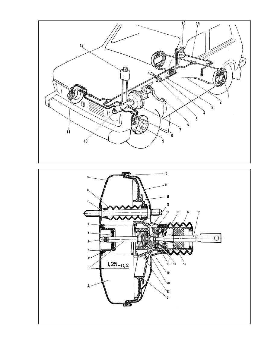
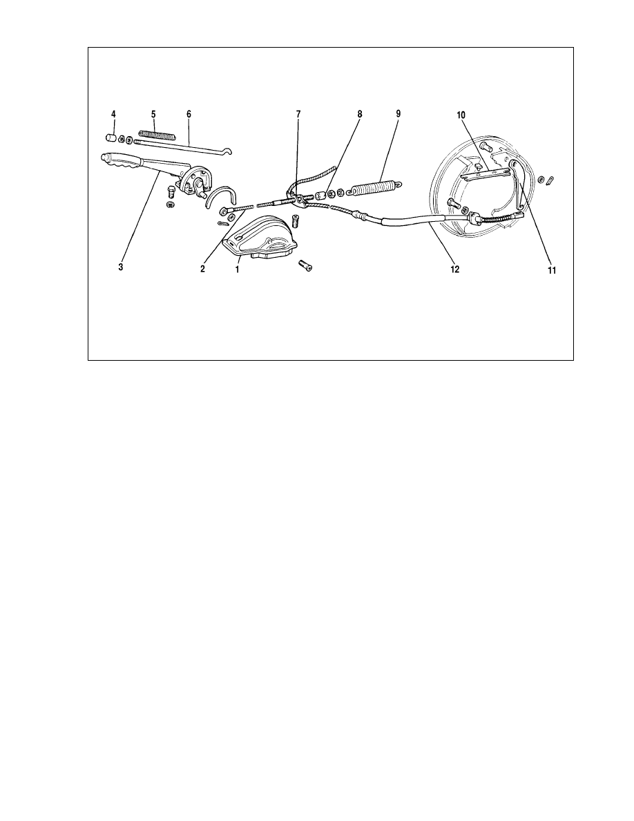
The design of the braking system is shown on fig. 6-1.
Fault diagnosis
Diagnosis
Remedy
Insufficient efficiency of braking
1. Leak of brake liquid from wheel
cylinders of front or rear brakes
2. Air in brake system
3. Damaged rubber sealings in
master brake cylinder
4. Damaged hydraulic system rub-
ber hoses
Spontaneous braking at working engine
1. Air inleak in servo unit between
valve housing and protective cap
Incomplete brake release on all wheels
1. No brake pedal free travel due
to wrong position of stop-signal
switch
2. Projection of servo unit adjusting
bolt in relation to fastening surface
of master cylinder exceeds 1.25
-0.2
mm
3. Jammed servo unit valve hous-
ing
4. Plugged compensation aperture
in master cylinder
5. Swollen master cylinder rubber
sealings due to penetration of
petrol, mineral oils and etc in liquid.
6. Jammed master cylinder piston
Snubbing of one wheel at released brake pedal
1. Loose or damaged return spring
of rare brake shoes
2. Jammed piston in wheel cylin-
der due to corrosion
3. Swollen wheel cylinder sealing
due to penetration of fuels and
lubricants in liquid
4. No gap between shoes and
drum
5. Wrong position of caliper in
relation to brake disc due to loose
bolts that are fastening carrier to
steering knuckle
6. Excessive runout of brake disc
(more than 0.15 mm)
Vehicle wandering or skidding at braking
1. Leak of brake liquid in one of
wheel cylinders
2. Jammed piston in brake wheel
cylinder
3. Clogged tube due to dent or
contamination
4. Different pressure in tyres
5. Wrong wheel alignment angles
6. Dirty or oily discs, drums and lin-
ings
7. Wrong adjustment of pressure
regulator
8. Faulty pressure regulator
Excessive pedal effort at braking
1. Plugged air filter
2. Jammed servo unit valve hous-
ing
3. Damaged hose between servo
unit and engine inlet pipe, or its
loose fastening on connectors
4. Oxidation of brake pedal metal
bushes or dry greasing in pedal
bushes
Scratch or squeal of brakes
1. Loose shoe return spring
2. Ovality of drums
3. Excessive oil on friction linings
4. Worn linings or trapped detri-
mental inclusions
5. Excessive disc runout or non-
uniform wear
Inspection and adjustment
Pipelines and connections - inspection
To prevent any occasional failure of the braking system care-
fully inspect all pipelines:
- metal pipelines should have no dents or cracks and should
lie far from sharp edges that can damage them;
- brake hoses should have no cracks on the outer surface and
should not get in contact with mineral oils and greasings that dis-
solve rubber; heavily depress the brake pedal and inspect the
hoses for bulges that will indicate malfunctions;
- all brake lines should be reliably fastened; loose fastening
will result in vibration causing damage;
- liquid leak through pipeline connections is not allowed; if
necessary, fully tighten the connections without deforming the
pipelines.
121
1. Renew bad components of
wheel cylinder, wash and dry
shoes and drums, bleed braking
mechanism
2. Expel air from system
3. Renew seals and bleed system
4. Renew hoses
1. Replace servo unit
1. Adjust switch position
2. Adjust bolt position (see fig. 6-2)
3. Replace servo unit
4. Clean aperture and bleed system
5. Carefully wash system with
brake liquid, renew damaged rub-
ber parts, bleed system
6. Check and replace, if necessary,
master cylinder, bleed system
1. Renew spring
2. Dismantle cylinder, clean and
wash all components, renew dam-
aged parts
3. Renew rings, wash system with
brake liquid
4. Adjust parking brake
5. Tighten securing bolts, renew
damaged parts if necessary
6. Grind disc, in case thickness is
less than 9 mm - renew
1. Renew air filter
2. Renew servo unit
3. Renew hose or tighten clips
4. Renew worn parts or greasing
1. Inspect return spring, replace if
necessary
2. Remachine brake drum
3. Clean pads using metal brush
with warm water and washing liq-
uid. Eliminate cause of liquid or
lubricate ingress
4. Renew pads
5. Grind disc, in case thickness is
less than 9 mm - renew
1. Renew seals and bleed system
2. Check and rectify piston sticking
in cylinder, renew damaged com-
ponents if necessary
3. Renew or clean tube, bleed sys-
tem
4. Adjust pressure
5. Adjust angles
6. Clean braking mechanism com-
ponents
7. Adjust position
8. Adjust or renew
122
Fig. 6-1. Braking system:
1 - rear brake wheel cylinder; 2 - parking brake rear cable; 3 - rear brake guide; 4 - parking brake front cable; 5 - parking brake lever; 6 - brake pedal; 7 - servo unit;
8 - second circuit pipeline; 9 - primary circuit pipeline; 10 - master cylinder; 11 - wheel cylinder block, front brakes; 12 - master cylinder tank; 13 - pressure regulator;
14 - pressure regulator control arm
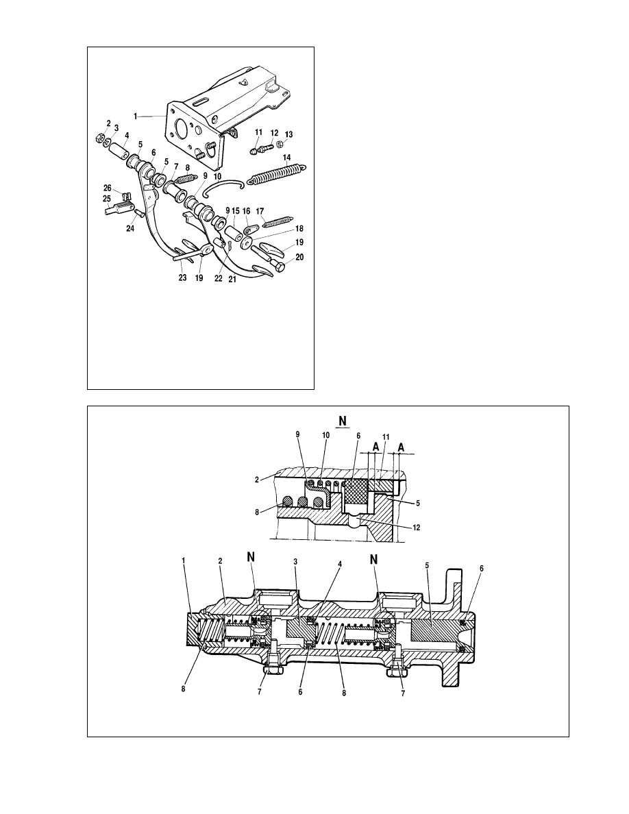
Fig. 6-2. Brake servo unit:
1 - rod; 2 - master cylinder flange sealing ring; 3 - servo housing cup; 4 - adjuster bolt; 5 - rod sealing; 6 - diaphragm return spring; 7 - pin; 8 - sealing boot; 9 - servo unit
housing; 10 - diaphragm; 11 - servo unit housing cover; 12 - piston; 13 - valve body boot; 14 - air cleaner; 15 - push rod; 16 - push rod return spring; 17 - valve spring;
18 - valve; 19 - valve body bush; 20 - reaction disc; 21 - valve body; A - vacuum chamber; B - atmospheric chamber; C, D - ports
Renew the components in the slightest doubt in serviceability.
Flexible hoses, irrespective their condition, should be
renewed after 100000 km or after 5 years of vehicle operation to
prevent sudden breaks due to aging.
After five years of operation it is recommended to renew the
brake liquid.
Servo unit -serviceability check
Press the brake pedal 5-6 times with the engine not working
to create in cavities A and B (fig. 6-2) identical pressure close to
atmospheric. Simultaneously, by effort applied to the pedal,
define, whether the valve housing 21 is jammed.
Stop the brake pedal in the middle of its travel and start the
engine. If the servo unit is OK, the brake pedal after engine start
should "go forward".
If the pedal does not "go forward", check the fastening of the
hose end piece, condition and fastening of the end piece flange
in the booster, hose-to-end piece fastening and connection to the
engine inlet pipe, because loose fastening or damage will signifi-
cantly reduce the underpressure in cavity A and performance effi-
ciency of the unit.
In case of vehicle spontaneous braking, check the servo unit
for leak-proofness with the engine running , first with a released,
and then depressed motionless brake pedal. "Sticking" of the pro-
tective cap 13 to the valve housing tail and hissing of inleaking air
will indicate insufficient tightness of the servo unit. In these cases
the unit should be renewed.
Brake drive adjustment
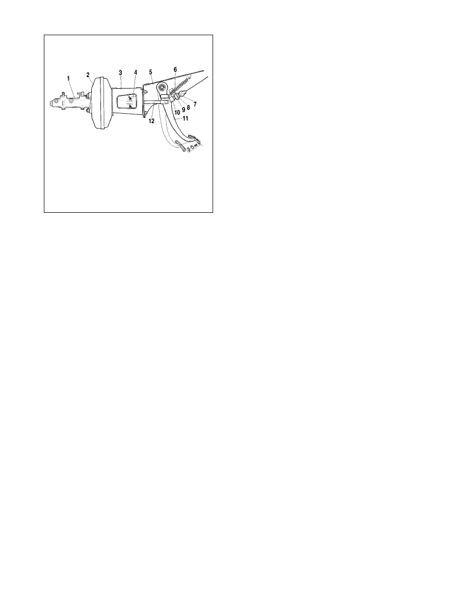
The free travel of the brake pedal with engine not working
should be 3-5 mm. This size is received by adjusting the position
of the stoplight switch 7 (fig. 6-3).
If the stoplight switch is too close to the pedal, it does not
come back to the initial position, valve 18 (see fig. 6-2), being
pressed to housing 21, separates cavities A and B, and it results
in incomplete release of wheels when the pedal is let off.
To adjust the stop-light switch position slacken nut 8 and by
rotating nut 9 (see fig. 6-3) position the switch so that its buffer
will slightly touch the pedal rest, thus the pedal free travel should
make 3-5 mm. After adjustment tighten nut 8.
ATTENTION. The brake pedal free travel adjustment is
made with the engine not working.
If the adjustment of the stoplight switch fails to remedy the
brake mechanism, disconnect the master cylinder from the servo
unit and check the protrusion of the adjusting bolt 4 (see fig. 6-2)
in relation to the fastening plane of the master cylinder flange
(size 1.25
-0.2
). This size can be established by holding with a spe-
cial key the end of rod 3, and with the other key screwing in or
undoing bolt 28.
Handbrake adjustment
Note. In the end of year 1995, the design of the handbrake
lever quadrant was changed - the first tooth of the sector became
double and thus the order of adjustment, marked below in the text
with a "*" sign, has changed.
If the handbrake does not hold the vehicle on a slope up to
25 % when moving the lever by 4-7 (2-8) * teeth of the quadrant,
adjust the handbrake in following order:
- shift the handbrake lever to the lowest position and then lift
by 1-2 teeth of quadrant (this operation is carried out only for the
gear sector of the "old" design);
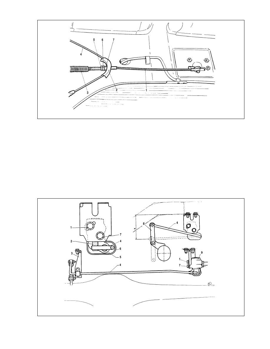
- slacken locknut 5 (fig. 6-4) and by turning the adjusting nut
6 take up cable 1;
- check the full travel of the handbrake lever, which should be
4-5 (2-4)* teeth on the quadrant, then tighten locknut 5.
Apply the brake pedal several times to ensure that the lever
travel does not change and wheels rotate without jamming at fully
lowered lever.
Note. If the cables were renewed, depress the brake pedal
two or three times applying force on the lever of approx. 392 N
(40 kgf). Thus the cables will be stretched.
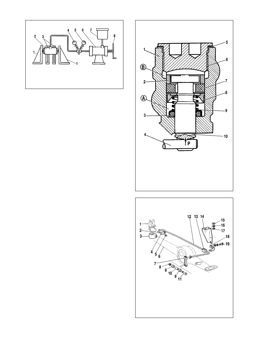
Pressure regulator serviceability check
Position the vehicle on a lift or over an inspection pit, clean
the pressure regulator and protective cover from dirt.
Carefully remove the protective cover from the pressure reg-
ulator, remove the remains of greasing and clean the "torsion-to-
piston" connection.
123
Fig. 6-3. Brake pedal:
1 - master cylinder; 2 - servo unit; 3 - bracket; 4 - sealant cup; 5 - clutch/brake
pedal mounting bracket; 6 - brake pedal return spring; 7 - stop light switch; 8, 9
- nuts; 10 - stoplight buffer; 11 - brake pedal; 12 - push rod
Ask an assistant to press the brake pedal with effort of 686-
784 N (70-80 kgf) and simultaneously observe the outcoming part
of the pressure regulator piston. If the piston moves by 0.5-0.9
mm in relation to the regulator housing, thus twisting the torsion
arm, the pressure regulator is efficient. Repeat the pedal
depressing 2-3 times to completely ensure the serviceability of
the pressure regulator.
If during pedal depressing the piston remains motionless, this
means that the piston became stuck to the housing due to corro-
sion, and pressure regulator renewal is required.
After ensuring the pressure regulator serviceability and no
brake liquid leaks between the piston and the pressure regulator
housing, apply a thin layer of Ñí-1 on the shaft and the acting part
of the piston, fill 5-6 gr. of this greasing in the rubber boot and refit
the cover.
Pressure regulator position adjustment
The pressure regulator position adjustment is required if the
fastening bolts became loose. Raise the vehicle rear axle.
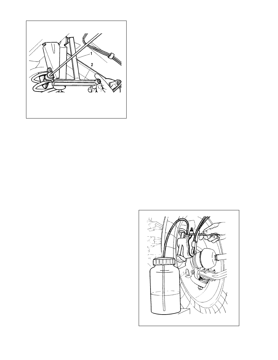
Disconnect arm 4 (fig. 6-5) from tie-rod 8 and fix on its end tool
67.7820.9519. Direct the core of the tool upwards until it will get
pressed against the car floor (fig. 6-6). This will be distance "X"
from the arm end to the body chassis arm (see fig. 6-5), equal to
(150±5) mm.
124
Fig. 6-5. Installation of the rear brake pressure regulator and adjustments:
1, 7 - regulator securing bolts; 2 - piston; 3 - thrust washer bracket; 4 - pressure regulator control arm; 5 - shaft; 6 - cap; 8 - tie rod; 9 - pressure regulator;X = 150 ± 5 mm
Fig. 6-4. Handbrake linkage:
1 - front cable; 2 - rear cable guide; 3 - front cable return spring; 4 - rear cable; 5 - locknut; 6 - adjusting nut; 7 - spacer
Raise the protective rubber cap 6 (see fig. 6-5) and, by turn-
ing the pressure regulator on the bolts, get a slight contact
between the arm and piston 2.
Keep the regulator in this position, fully tighten bolts 1 and 7,
then apply a thin layer of greasing Ñí-1 on shaft 5 and the work-
ing part of piston 2. Fill 5-6 gr. of the same greasing in rubber cap
6 and refit.
Remove tool 67.7820.9519 and reconnect the arm end with
tie-rod 8.
Hydraulic system bleeding
Air, that got into the brake hydraulic system during replace-
ment of pipelines, hoses, sealing rings or due to system leak,
causes increase of brake pedal free travel, its "softness" and con-
siderably reduces braking efficiency.
Before bleeding the brake system ensure the leak-proofness
of all system units and their connections, check and if necessary
fill the tank with brake liquid up to normal level. Then carefully
clean from dirt and dust the bleeding connectors and remove the
protective caps.
Fit a rubber hose on the connector (fig. 6-7) for liquid drain,
and place its free end in a transparent vessel partially filled with
liquid.
Sharply depress the brake pedal 3-5 times, with 2-3 sec.
intervals, undo the connector by 1/2-3/4 turn with the pedal
depressed. Continue to press the pedal, bleed liquid with air
through the hose into the vessel. After the brake pedal will reach
the lowest front position and the liquid drain through the hose will
be finished, tightly close the bleeding connector. Repeat these
operations until all air bubbles will be bleeded from the hose.
Then, keeping the brake pedal in depressed position, tightly close
the bleeding connector and take off the hose. Wipe dry the con-
nector and refit the protective cap.
All above operations should be carried out through the upper
connectors first on the right rear wheel, the most remote from the
master cylinder, then further clockwise: the left rear wheel, left
and right front wheels. Thus, air from one circuit will be removed.
To bleed the other circuit use the lower connectors on the cylin-
der block of the left and right front brakes. Bleeding can be start-
ed from the right or left wheel.
During bleeding maintain normal liquid level in the hydraulic
system tank. If there is no air in the system the brake pedal
should go no more than 1/2-3/4 of full travel.
To exclude the influence of the servo unit and the pressure
regulator on bleeding the hydraulic system, it should be carried
out with the engine not working and rear wheels loaded (do not
raise the rear part of the vehicle).
If the brake liquid was completely drained from the system,
do the following before bleeding air:
- undo the bleeding connector by 1.5-2 turn˚ on all wheel
cylinders;
- sharply depress the brake pedal and smoothly release it,
close the connector when liquid will be drained. Then bleed the
hydraulic system, as described above.
If, despite continuos bleeding, the air bubbles still come out
from the hose into the vessel, it means air penetrates into the sys-
tem through damaged pipelines, because of insufficient tightness
of connections or due to malfunction of the master or wheel cylin-
ders.
When bleeding the vehicle, the braking system of which has
worked for a long time, renew the brake liquid.
If the brake liquid is suitable for further use, carefully filter the
liquid, and then desilt in a tightly closed vessel.
125
Fig. 6-6. Installing tool 67.7820.9519 to adjust the position of the rear
brake pressure regulator:
1 - tool 67.7820.9519; 2 - pressure regulator control arm
Fig. 6-7. Bleeding the brake hydro system
Clutch and brake pedal bracket
Removal and refitting. To remove the pedal bracket:
- remove the steering shaft bracket, as mentioned in section
"Steering";
- disconnect the servo unit push rod from the brake pedal,
having removed lock shackle 26 (fig. 6-8) and taken out pin 24;
- disconnect the wires from the stoplight switch;
- undo the nuts that are fixing the brackets of the servo unit
and pedals to the body front and remove the bracket in assembly
with the servo unit and the master cylinder, and then the clutch
and brake pedal bracket.
Refitting is carried out in reverse sequence. Pay attention to
correctly refit the push rod in the jack of the clutch master cylin-
der piston.
Dismantle and reassembly. To dismantle, remove the
clutch pedal servo unit spring 14, remove return springs 8 and 17,
undo nut 2 of bolt 20, take out the bolt and remove the pedals
together with bushes.
To remove and refit the springs use tool A.70017.
Reassembly of the master cylinder is carried out in reverse
order. When reassembling, grease with ãàíéã-24 the pedal
bushes, spring ends, connection places between the push rods
and pedals, and the push rod end adjoining the piston of the
clutch master cylinder.
126
Fig. 6-8. Clutch/brake pedal bracket, exploded view:
1 - bracket; 2 - nut; 3 - spring washer; 4 - brake pedal inner bush; 5 - brake pedal
outer bush; 6 - brake pedal; 7 - distance sleeve; 8 - brake pedal return spring;
9 - clutch pedal outer bush; 10 - hook; 11 - cap; 12 - clutch pedal limit screw;
13 - nut; 14 - servo spring; 15 - clutch pedal inner bush; 16 - plate;
17 - clutch pedal return spring; 18 - washer; 19 - pad; 20 - bolt; 21 - clutch pedal;
22 - cotter pin; 23 - clutch pedal push rod; 24 - pin; 25 - push rod;
26 - lock shackle
Fig. 6-9. Master cylinder:
1 - plug; 2 - cylinder body; 3 - front brake drive piston; 4 - washer; 5 - rear brake / front additional drive piston; 6 - sealing ring; 7 - stop screws; 8 - piston return springs;
9 - spring cup; 10 - seal holding spring; 11 - spacer ring; 12 - inlet port; A - compensation port (clearances between seal 6, ring 11 and piston 5)
Check and repair. At hard pedal movement examine the
working surfaces of pedals, bushes and shaft.
If there will be small risks or traces of oxidation on surfaces of
metal parts, grind them slightly with sandpaper; renew worn outer
plastic bushes on pedals.
Check the spring tension. The length of the brake pedal
spring should be: under load of 12.8±1.96 N (1.3±0.2 kgf) - 80
mm, under load of 117.5±5.88 N (12±0.6 kgf) - 160 mm.
The clutch pedal return spring has the length of 130 mm
under load of 36.26-30.38 N (3.7 – 3.1 kgf), and 155 mm under
load of 49.49 – 42.63 N (5.05 – 4.35 kgf). Length of the clutch
servo unit spring under load of 219.52 – 180.32 N (22.4 – 18.4
kgf) should be 120 mm, and under load of 645.82 – 529.22 N
(65.9 – 53.9 kgf) - 152 mm.
Servo unit
Removal and refitting. When removing the servo unit, do
not disconnect the brake hydrodrive master cylinder from the
hydraulic system to avoid air penetration.
The order of removal:
- disconnect the servo unit push rod from the pedal;
- undo the nuts fastening the master cylinder to the unit,
remove it from pins and move aside;
- disconnect the hose from the servo unit;
- undo the nuts fastening the servo unit bracket to the body
front and remove the unit in assembly with the bracket.
Refitting of the servo unit is carried out in reverse order.
Master cylinder
The design of the master cylinder is shown on fig. 6-9.
Removal and refitting. Disconnect the flexible hoses from
the master cylinder and close the openings of hoses and con-
nectors on the cylinder to prevent liquid leak from reservoir and
penetration of dust, dirt or foreign matters.
Undo the tube nuts and disconnect from the master cylinder
the steel pipelines that are carrying liquid to wheel cylinders of
front and rear brakes.
Remove the cylinder, having undone the nuts that are fas-
tening it to the servo unit.
Refitting of the master cylinder is carried out in reverse
sequence. After refitting the cylinder, bleed the hydraulic system
to expel air.
Dismantle and reassembly. Remove connectors 2 (fig. 6-
10) with connecting bushes 3, turn out lock bolts 5 and take out
all components in order specified on fig. 6-10.
The reassembly of the cylinder is carried out in reverse
sequence. Grease all components with brake liquid. When
reassembling, use tool 67.7853.9543.
127
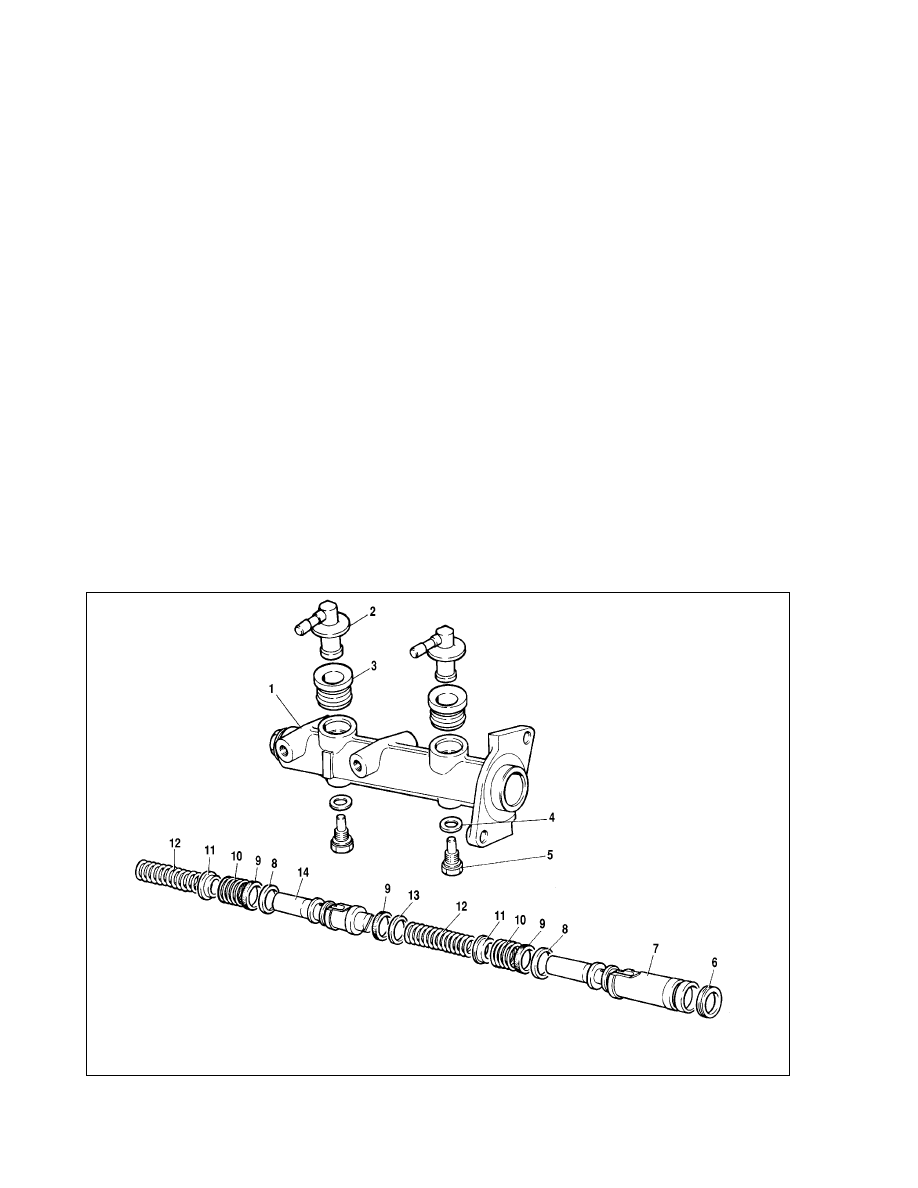
Fig. 6-10. Master cylinder components:
1 - cylinder body; 2 - connector; 3 - connector bush; 4 - sealing washer; 5 - lock bolt; 6, 9 - sealing rings; 7 - rear brake / front additional drive piston; 8 - distance ring;
10 - sealing ring holding spring; 11 - spring cup; 12 - piston return spring; 13 - washer; 14 - front brake drive piston
Inspection of components. Before reassembly, wash all
components with isopropyl alcohol; dry by a jet of compressed air
or wipe with a clean cloth, but do not allow their contact with min-
eral oil, kerosine or diesel fuel, which can damage the sealings.
Note. Time of washing the sealing rings in isopropyl alcohol
is no more than 20 seconds with subsequent drying by com-
pressed air.
The cylinder mirror and working surfaces of pistons should be
completely clean, without rust, marks and other defects. No
excessive gap between the cylinder and pistons is allowed.
Every time, when dismantling the cylinder, renew the seal-
ings, even if they are in good condition.
Check the piston spring tension, the length of which should
be 41.7 mm under load of 42.18±3.92 N (4.3±0.4 kgf), 21 mm
under load of 90.64±8.83 N (9.24±0.9 kgf), in free state - 59.7
mm.
Master cylinder leak-proofness check. Place the master
cylinder on a test bench and connect it to the bench elements, as
shown on fig. 6-11.
Open the bench bleeding valves 1 and, by moving the mas-
ter cylinder piston several times by its full stroke, bleed the sys-
tem. Then close valves 1. Rotate flywheel 5, slowly move the
master cylinder pistons until pressure monitored by manometer 2
will reach 12.5 MPA (125 kgf/cm
2
). In this position block the mas-
ter cylinder push rod. Specified pressure should remain constant
for no less than 5 seconds.
In case of liquid leaks or drop of established pressure during
5 seconds, renew the cylinder piston sealings.
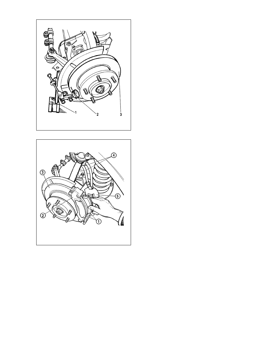
Front brakes
The design of the front brake is shown on fig. 6-12.
Before repairing the brakes, carefully wash them in warm
water with washing liquids and immediately dry with a jet of com-
pressed air.
ATTENTION. Do not use petrol, diesel fuel, trichloroeth-
ylene or any other mineral solvents to clean the brakes, as
these materials damage the cylinder sealings.
Removal and refitting
Removal. Lift the front part of the vehicle, place it on supports
and remove the wheel.
Remove the hose guide brackets. Undo the bypass bolts, dis-
connect from the cylinder block hoses 10 (see fig. 6-12), avoid
penetration of dirt into the cylinder cavities. Plug the openings of
the cylinder block and hoses.
Unbend the edges of the front brake splash guard, undo the
bolt fastening the brake to the steering knuckle (fig. 6-13) and
remove the brake assembly.
The refitting of the front brake is carried out in sequence
reverse to removal.
After refitting, fill the brake liquid in the reservoir and bleed
the system to expel air from the hydraulic drive.
Dismantle and reassembly
Take out pins, then shafts 5 (see fig. 6-12), hold the clamping
levers 3 so that not to loose the springs. Remove the clamping
levers and their springs, and then caliper 7 in assembly with block
1. Remove brake pads 2.
Take out cylinder block 1 from the caliper grooves by moving
apart the caliper grooves up to 118.5 mm and pressing on lock
12. Remove the dust caps 3 (fig. 6-14) from cylinders.
128
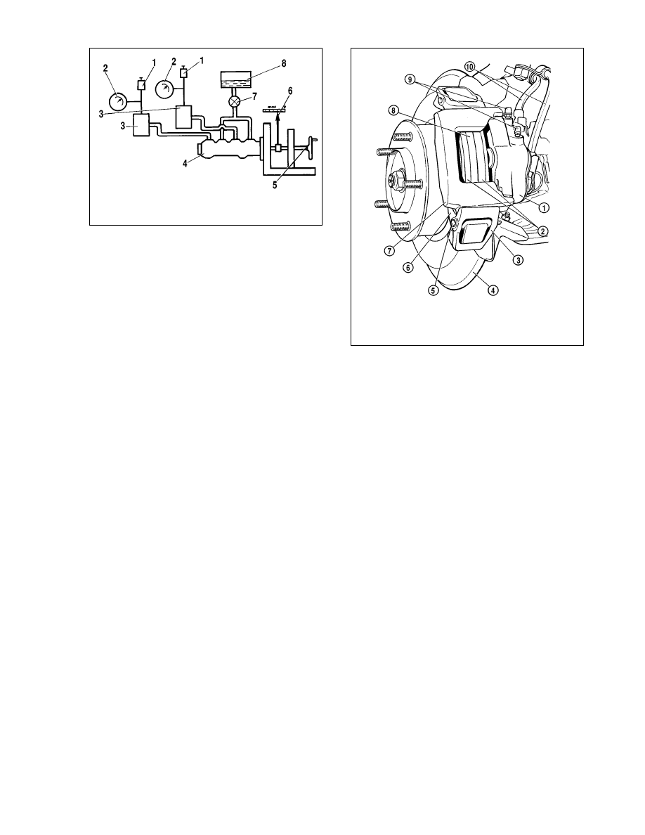
Fig. 6-12. Front wheel brake system:
1 - cylinder block; 2 - brake pads; 3 - caliper clamping lever; 4 - splash guard;
5 - clamping lever shaft; 6 - carrier; 7 - caliper; 8 - brake disc; 9 - bleeders;
10 - brake hoses
Fig. 6-11. Checking the leak-proofness of the master cylinder:
1 - test-bench bleeding valve; 2 - manometer; 3 - reservoir; 4 - master cylinder;
5 - flywheel; 6 - pushrod shift indicator; 7 - vent; 8 - vessel
Forcing a jet of compressed air through the aperture for
brake liquid, push out pistons 14 from the cylinder block and take
out sealing rings 4.
The reassembly of the front brake is carried out in sequence
reverse to dismantle. When assembling, lubricate the sealing
rings, pistons and cylinder mirrors with brake liquid, and grease
the protective caps with Ñí-1.
Components inspection
Carefully examine all components, having previously washed
them in warm water with washing liquid and dried by a jet of com-
pressed air.
If on pistons and on cylinder mirrors any traces of wear or
jamming are found, renew the cylinder block complete with pis-
tons.
Note. In all cases, when the piston is taken out from the cylin-
der, it is recommended to renew the dust cap and the sealing
rings in the cylinder block flutes to ensure satisfactory operation
of the system.
Brake disc runout check
Check the axial runout of the brake disc without removing it
from the vehicle (fig. 6-15). The maximum allowable runout by
the indicator is 0.15 mm; if the runout is greater, it is necessary
to grind the disc, but the final thickness of the disc after grinding
should be no less than 9.5 mm. In case of damage or very deep
risks, and also if wear exceeds 1 mm on each side, renew the
disc.
Replacement of brake pads
Renew the pads, if the friction lining thickness has decreased
to 1.5 mm.
To replace the pads do the following:
- remove the pins from the shaft of the upper clamping lever,
take out the shaft and remove the lever; remove the caliper
129
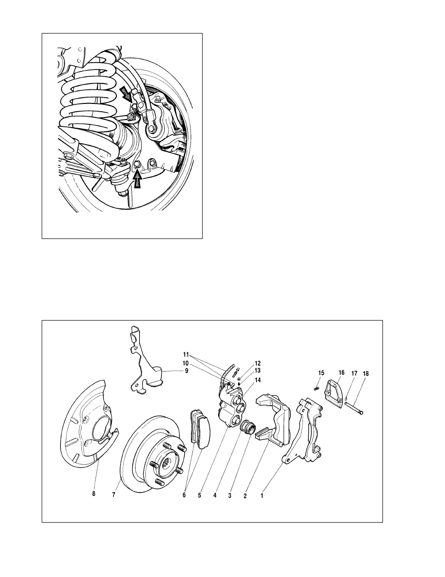
Fig. 6-13. Removing the front brake:
Arrows are pointing to the bolts that should be undone to remove the front brake
Fig. 6-14. Front brake components:
1 - carrier; 2 - caliper; 3 - piston cap; 4 - sealing ring; 5 - cylinder block; 6 - brake pads; 7 - brake disc; 8 - caliper dust cover; 9 - brake splash guard; 10 - bleeder;
11 - brake hoses; 12 - cylinder block detent; 13 - detent spring; 14 - piston; 15 - clamping lever spring; 16 - clamping lever; 17 - pin; 18 - clamping lever shaft
assembly and take out the worn pads from the carrier grooves
(fig. 6-16);
- carefully depress the pistons in cylinders to a stop, paying
attention not to splash the liquid from the master cylinder reser-
voir, and place new brake pads in carrier grooves;
- move the lower directing splay on the caliper under the
lower clamping lever, press the caliper to the pads, insert the
lever shaft with the head facing the wheel and fix the pins.
The pads should be changed simultaneously on the right and
on the left brakes.
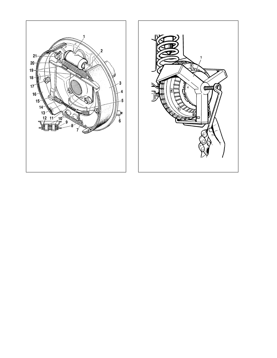
Rear brakes
The design of the rare brake is shown on fig. 6-17.
Removal and dismantling
Lift the rear part of the vehicle and take off the wheel. Take
care of possible liquid spillage from the tank.
Using puller 67.7823.9519 (fig. 6-18) remove the brake drum.
Disconnect the cable end piece from the shoe manual lever 18
(see fig. 6-17), remove the cotter pin, press pin 21 and remove
the lever. Using flat-nose pliers disconnect the upper 2 and lower
7 return springs.
Turn the cups of the steady post 17, take them off together
with posts, springs and bottom cups; remove shoes 8 and 16 and
expander strut 20. Disconnect from the wheel cylinder 1 pipeline
and plug the openings of the cylinder and pipeline. Remove the
wheel cylinder. To replace the brake backplate 4 remove the axle
shaft, as specified in chapter "Rear axle", and disconnect the rear
cable 13, having turned out two bolts that are fastening it to the
brake plate 4.
Assembly and refitting
Assembly and refitting is carried out as follows.
Fit and fix the wheel cylinder on the brake backplate, attach it
to the pipeline and fully tighten the connector nut.
Attach the shoe manual lever 18 (see fig. 6-17) and refit the
brake shoes with expander strut 20, then insert posts 17 with
springs and bottom cups, put the upper springs and fix them on
racks by turning one or other way. Ensure, that the shoe ends
have correctly settled down in the support jacks on the wheel
cylinder pistons and on the backplate. Attach the rear cable end
piece 15 to lever 18.
Fit the brake drum, previously having greased the landing
shoulder of the axle shaft with graphite lubricant or greasing
ãëñ-15 and fully tighten the drum fastening bolts.
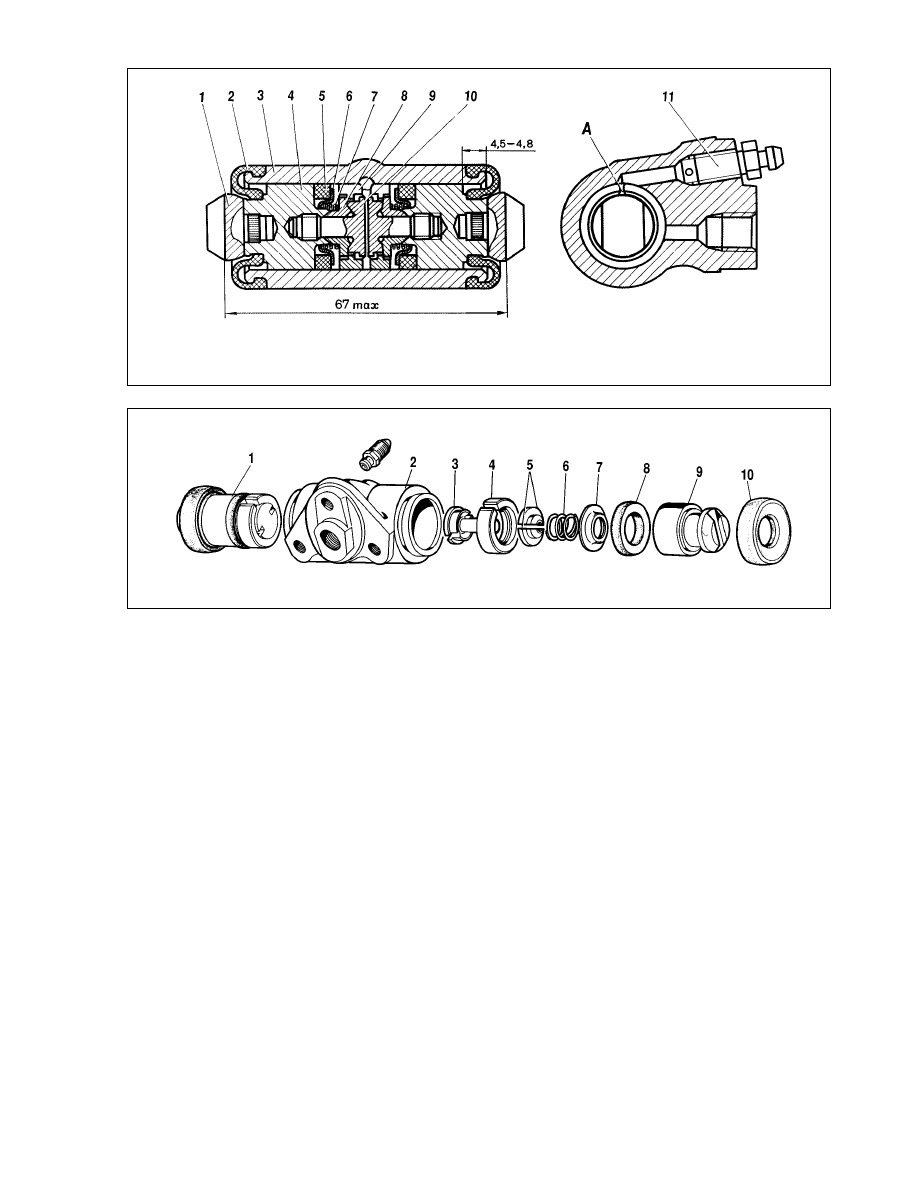
Wheel cylinders - dismantle and reassembly
The dismantle and reassembly of the wheel cylinders is car-
ried out as follows.
Remove protective caps 2 (fig. 6-19), then press out from the
cylinder body 3 pistons 4 in assembly with the components of the
automatic shoe-drum clearance adjuster.
Place the piston in assembly with the automatic adjuster on a
special tool so that the ledges of the tool will cover the head of the
thrust screw 3 (fig. 6-20). Using a screwdriver and by turning pis-
ton 9, turn out thrust screw 3 from the piston. Remove sealing 8
with support cup 7 and retainers 5 from the screw. Separate
thrust ring 4 and thrust screw 3.
130
Fig. 6-16. Replacing the brake pads:
1 - brake pads; 2 - carrier; 3 - brake disc; 4 - brake hoses; 5 - cylinder block
(complete with caliper)
Fig. 6-15. Checking the brake disc runout:
1 - magnetic block; 2 - indicator; 3 - brake disc
The reassembly of the automatic adjuster and the wheel
cylinder is carried out in reverse sequence, paying attention to
the following:
- piston thrust screws are tightened to torque 4-7 N•m (0.4-
0.7 kgf•m);
- slot A (see fig. 6-19) on thrust rings should be directed ver-
tically upward; vertical deviation should be no more than 30
°.
Such position of the slot provides complete air bleeding from the
brake mechanism;
- for preliminary compression of thrust rings the pistons are
press-fitted in the cylinder body with a special tool having the
form of a cylinder with a cone inner aperture;
- the effort of press-fitting the piston in the cylinder should be
no less than 350 N (35 kgf); in case effort was less than 350 N
(35 kgf) - replace the thrust ring;
- when press-fitting the piston in the cylinder it is necessary to
maintain the sizes of 4.5-4.8 mm and 67 mm (maximum) (see fig.
6-19) for free landing of the brake drum;
- before refitting the components in the cylinder body thickly
grease them with brake liquid.
After reassembly check the movement of each piston in the
cylinder body. They should freely move within the limits of 1.25-
1.65 mm. The last established in place is the protective cap 2.
Component inspection
Wheel cylinders. Ensure the cleanness of working surfaces
of the cylinder, pistons and thrust rings. The surfaces should be
absolutely smooth, without roughness, to avoid liquid leak and
premature wear of sealings and pistons. The defects on the cylin-
der mirror can be eliminated by lapping or polishing. However, no
increase of the cylinder inner diameter is allowed.
Inspect screw 3 (see fig. 6-20), spring 6, thrust cup 7 and
retainers 5. If necessary, renew damaged components.
Renew sealings 8. Inspect protective caps 10 and renew if
necessary.
Shoes. Carefully check the shoes for damages or deforma-
tions.
Check the tension of the upper and lower return springs; if
necessary, renew.
The springs should have no residual deformations when
stretched with effort of 350 N (35 kgf) for lower springs and 420
N (42 kgf) - the upper ones.
Check the linings for dirt or traces of greasing, if necessary,
carefully clean with metal brush and wash with white-spirit,
besides, check for leaks of greasing inside the drum; eliminate
malfunctions. Renew shoes, if the friction lining thickness is less
than 1.5-2 mm.
131
Fig. 6-17. Rear wheel brake mechanism:
1 - wheel cylinder; 2 - upper return spring; 3 - friction lining; 4 - backplate;
5 - inner plate; 6 - rear cable sheath; 7 - lower return spring; 8 - front brake shoe;
9 - thrust plate; 10 - rivet; 11 - oil deflector; 12 - guide plates; 13 - handbrake
rear cable; 14 - rear cable spring; 15 - rear cable end; 16 - rear brake shoe;
17 - steady post; 18 - shoe manual control lever; 19 - rubber pads;
20 - expander strut; 21 - shoe manual control lever pin
Fig. 6-18. Removing the brake drum:
1 - remover tool 67.7823.9519
Brake drums. Examine the brake drums. If the working sur-
faces have deep risks or excessive ovality, chisel the drums.
Then grind on a machine tool with abrasive fine stones. This will
help to increase the lining durability, and improve the uniformity
and efficiency of braking.
The maximum allowable increase of drum nominal diameter
(250 mm) after turning and polishing is 1 mm. These dimension
limits should be strictly observed, otherwise, the durability of the
drum, and the efficiency of braking will be decreased due to
reduction of drum rigidity.
Rear brake wheel cylinder -test-bench inspection
Position cylinder 2 (fig. 6-21) on the test bench, attach the
pipeline from the manometers and bleed the system.
Adjust rests1 so that the wheel cylinder pistons are rested
against them.
Check for liquid leak. Connect a low pressure manometer 4.
Slowly rotate flywheel 8 to obtain liquid pressure of 0.05 MPA
(0.5 kgf/cm
2
) as read by the pressure gauge 4.
Ensure that pressure holds steady for 5 minutes. Repeat sim-
ilar test at liquid pressure of 0.1 - 0.2 - 0.3 - 0.4 - 0.5 MPA (1 - 2
- 3 - 4 - 5 kgf/cm
2
).
Reduce pressure and connect a high pressure manometer 5.
Ensure that pressure holds steady for 5 minutes, repeat similar
test at liquid pressure of 5 - 10 - 15 MPA (50 - 100 - 150 kgf/cm
2
).
There should be no pressure decrease due to liquid leak
through sealing elements, pipeline connections, bleeding con-
nectors or through casting pores.
An insignificant reduction of pressure (no more than 0.5 MPA
(5 kgf/cm
2
) during 5 minutes is permissible, especially at high
pressure, due to shrinkage of sealings.
Rear brake pressure regulator
Removal and refitting. Disconnect arm 12 (fig. 6-22) from
tie-rod 7, and holder 18 from bracket 14 and shackle that is fas-
tening the pipelines going to the pressure regulator.
Disconnect the components of muffler mounting from the
body and move the pipeline with the mufflers aside.
Undo the bolts fastening the regulator on the bracket and the
bracket on the car body, remove the regulator bracket, and then,
having lowered the regulator downward, disconnect the
pipelines.
132
Fig. 6-19. Wheel cylinder:
1 - shoe abutment plate; 2 - cap; 3 - cylinder body; 4 - piston; 5 - seal; 6 - backing cup; 7 - spring; 8 - retainers; 9 - thrust ring; 10 - thrust screw; 11 - bleed screw; A - slot
in thrust ring
Fig. 6-20. Wheel cylinder components:
1 - piston assembly; 2 - cylinder body; 3 - thrust screw; 4 - thrust ring; 5 - retainers; 6 - spring; 7 - backing cup; 8 - seal; 9 - piston; 10 - cap
Remove the regulator and disconnect the arm. Plug all open-
ings of the pressure regulator and pipelines.
Refitting of the pressure regulator is carried out in reverse
sequence. Before tightening the regulator fastening bolt place
tool 67.7820.9519 (see fig. 6-6) on the end of the regulator arm.
Direct the tool bar upwards to the car body. Thus, the distance of
(150+5) mm (see "Pressure regulator position adjustment")
between the end of arm 2 and underframe side member is
obtained.
Raise protective cap 3 (see fig. 6-22) and by turning the reg-
ulator on the fastening bolts, obtain a slight contact between the
arm end and the regulator piston.
Fix the regulator in this position, fully tighten the fastening
bolts, then apply a layer of greasing Ñí-1 or "Ñàíéê" on shaft 2
and the protruding part of the piston. Refit rubber cap 3 having
applied 5-6 gr of the same greasing.
Remove tool 67.7820.9519 and reconnect the arm end to tie-
rod 7, previously having covered the bushes of the rod-to-arm
connection with greasing Ñí-1 or Ñàíéê.
Attach the gas release system pipelines to the car body.
Bleed the brakes to expel air from the rear brakes.
Dismantle and reassembly. Use key A.56124 to turn out the
plug, remove lining 5 (fig. 6-23), take out piston 10, distance
sleeve 2, sealing 7, plate 8, spring 9 and thrust washer with seal-
ing ring 3.
When reassembling, which is carried out in reverse
sequence, grease all components with brake liquid.
ATTENTION. To differentiate the VAZ-2121 and -21213
pressure regulators from others of similar design, there is a
groove on the bottom part of the piston.
Wash the components with isopropyl alcohol or brake liquid
and inspect. The components surfaces should have no marks
and roughness.
Check the spring tension, length in free condition should be
17.8 mm, and under load of 76.44 - 64.68 N (7.8-6.6 kgf) - 9 mm.
Renew damaged components, sealings and sealing rings.
133
Fig. 6-21. Checking the rear brake wheel cylinders:
1 - piston rests; 2 - cylinder under check; 3 - cylinder bracket; 4 - low pressure
manometer; 5 - high pressure manometer; 6 - cylinder for building up pressure;
7 - reservoir; 8 - flywheel
Fig. 6-22. Pressure regulator linkage components:
1 - pressure regulator; 2 - regulator control arm shaft; 3 - cap; 4 - lock plate;
5 - bolt with spring washer; 6 - rear axle beam; 7 - pressure regulator control
arm-to-rear axle bracket connecting tie-rod; 8 - bolt washer; 9 - plastic bush;
10 - distance sleeve; 11 - tie-rod securing bolt; 12 - pressure regulator control
arm; 13 - arm thrust bush; 14 - bush bracket; 15 - washer; 16 - spring washer;
17 - nut; 18 - bush clamp; 19 - clamp-to-bracket fastening bolt
Fig. 6-23. Rear brake pressure regulator, non-operating position:
A - normal pressure chamber; B - adjustable pressure chamber; P - force from
arm 4; 1 - regulator housing; 2 - distance sleeve; 3 - sealing ring; 4 - regulator
control arm; 5 - gasket; 6 - plug; 7 - seal; 8 - spring cup; 9 - piston spring;
10 - piston
Handbrake
Removal and refitting. Place the handbrake lever in the
lowest position, disconnect the cable ends from the brake shoe
levers (see "Rear brake").
Slacken locknut 5 (see fig. 6-4) and adjusting nut 6, remove
return spring 9 (fig. 6-24), then completely undo the locknut and
nut.
Take out the front end pieces of the rear cable from the
brackets on the floor, and the cable sheath from the brackets on
the rear axle beam, and remove the rear cable 12.
Remove the lever protective cover and then the lever assem-
bly and the front cable.
Take out the pin and remove the thrust washer, disconnect
the front cable from the handbrake linkage lever.
The handbrake is refitted in reverse sequence with subse-
quent adjustment (see "Handbrake adjustment"). When refitting,
grease with ãàíéã-24 or ãëñ-15 the rear cable guide, the
handbrake lever shaft and the front cable end.
Check and repair. Carefully inspect the components of the
handbrake mechanism.
If breakage or wire scuffing is detected, renew the cable.
Make sure, that the quadrant teeth and handle lock are not
damaged; worn components should be replaced.
Check the condition of the spring. It should provide the lever
return to the released position.
Inspect the rear cable sheath and the fastening of end pieces
on the sheath, and ensure, that the cable freely moves inside the
sheath. Replace the cable in case of sheath damage and loose
end piece fastening.
134
Fig. 6-24. Handbrake linkage components:
1 - cover; 2 - front cable; 3 - lever; 4 - pushbutton; 5 - tie rod spring; 6 - lock tie-rod; 7 - rear cable guide; 8 - distance sleeve; 9 - return spring; 10 - expander strut;
11 - manual shoe operating lever; 12 - rear cable
Wyszukiwarka
Podobne podstrony:
Niva 1 7 Instrukcja eng6
Niva 1 7 Instrukcja eng2
Niva 1 7 Instrukcja eng7
Niva 1 7 Instrukcja eng5
Niva 1 7 Instrukcja eng3
Niva 1 7 Instrukcja eng8
Instrukcja obsługi (PL) Lada Niva cz 2
Instrukcja obsługi (PL) Lada Niva cz 1
wykład 6 instrukcje i informacje zwrotne
więcej podobnych podstron