
ëhapter 7. Electrical system
Wiring and fuses
The electrical system is of the single-wire negative earth
type. The vehicle basic wiring diagram is illustrated in Fig.7-1.
Most electrical circuits are powered when the ignition is
switched on. Regardless the ignition switch position, the follow-
ing functions are available: horn, stoplight, cigarette lighter, inte-
rior lamps, inspection lamp, hazard warning flashers, exterior
lighting and main beam.
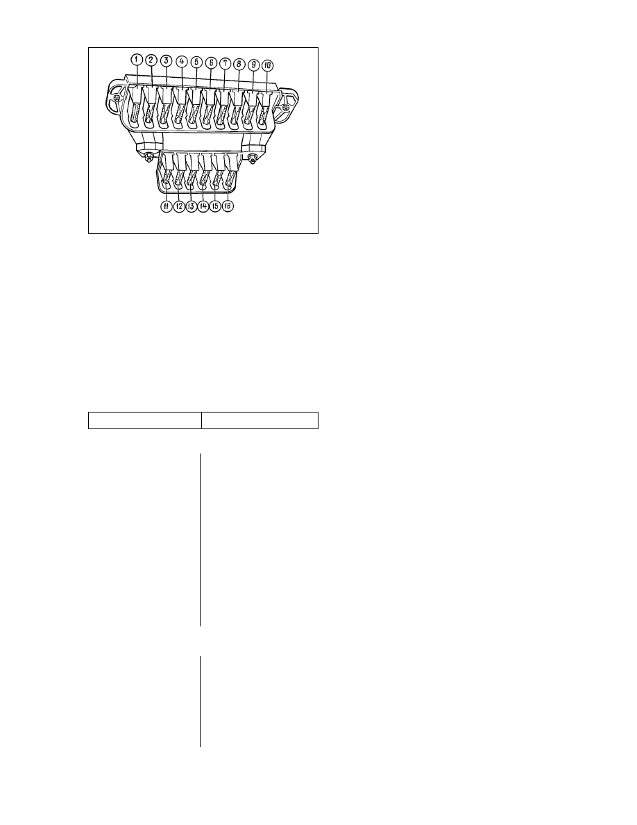
Most of the vehicle electrical circuits are protected by fuses,
which are located beneath the facia, at the left-hand side of the
steering column (Fig.7-2). There are no fuses for battery charg-
ing, ignition and engine start-up (starter and alternator) circuits,
main/dipped beam relay. Extra fuses 11, 12, 14, 16 are provided
in the additional fusebox to be used for alternative vehicle speci-
fications.
Before renewing a blown fuse, isolate and remedy the cause.
Before attempting to diagnose any electrical fault, refer to Table
7-1 to study the relevant wiring diagram protected by a failed
fuse.
Table 7-1
Fuse-protected circuits
Fuse No
Circuit protected
1 (16 Ä)
Heater blower motor
Headlight wiper relay (winding) and headlight wiper
motors at all wiper positions, except initial
Heated tailgate relay (winding)
Tailgate wipe/wash motors
Windscreen washer motor
2 (8 Ä)
Windscreen wiper relay and motor
Direction indicators and indicators flasher relay
(turn indication mode)
Direction indicator warning light
Tail lights (reversing lamp)
Alternator winding (at engine start-up) and
low battery warning light*
Differential lockup warning light
Relay and handbrake-on warning light
Low brake fluid warning light
Oil pressure warning light
Coolant temperature gauge
Low fuel gauge and fuel reserve warning light
Tachometer
3 (8Ä)
Left-hand headlight (main beam)
Main beam warning light
4 (8 Ä)
Right-hand headlight (main beam)
5 (8 Ä)
Left-hand headlight (dipped beam)
6 (8 Ä)
Right-hand headlight (main beam)
7 (8 Ä)
Left-hand front lamp (side marker light)
Right-hand front lamp (side marker light)
Number plate light
Side marker warning light
8 (8Ä)
Right-hand rear lamp (side marker light)
Left-hand rear lamp (side marker light)
Instrument panel illumination
Heater control illumination lamp
Cigarette lighter illumination
Switch illumination
9 (16Ä)
Direction indicators and indicators hazard relay
(hazard flashers mode)
Tailgate heating element and switch-on relay
(contacts)
10 (16Ä)
Horn
Inspection lamp socket
Interior lamps
Tail lights (stop lamp bulbs)
13 (8Ä)
Tail lights (fog lamps)
Headlight wiper motors at start-up and
when wiper arms pass initial position
Headlight wiper relay (contacts)
Headlight washer motor
15 (16Ä)
Cigarette lighter
________________________________________
* Pre-1996 vehicles were fitted with a voltmeter (protected by fuse No2) instead
of the relevant warning light in the instrument cluster.
In all wiring diagrams, covered by chapter «Electrical sys-
tem», the letters are used to denote the respective colour code:
the first letter stays for the wire colour Òode, while the second let-
ter - for the tracer colour code (Table 7-2).
Table 7-2
Fuse colour codes
Letter
Colour
Å
White
É
Blue
Ü
Yellow
á
Green
ä
Brown
é
Orange
è
Red
ê
Pink
ë
Grey
ó
Black
WARNING. Always disconnect the battery negative lead
when making repairs on the vehicles or its electrical system.
When replacing fuses or checking wiring, never use fuses
other than those specified for a particular vehicle model as
it may damage current tracks in the fuse and relay box.
135
136
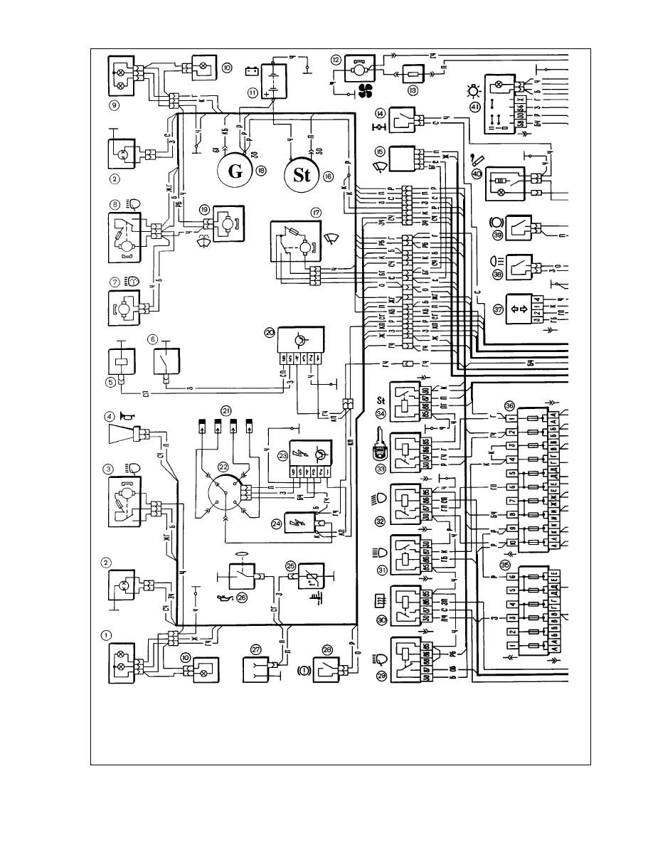
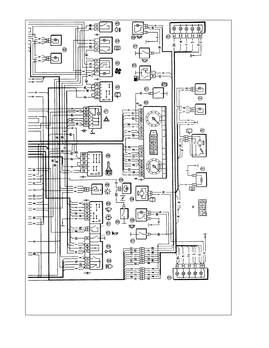
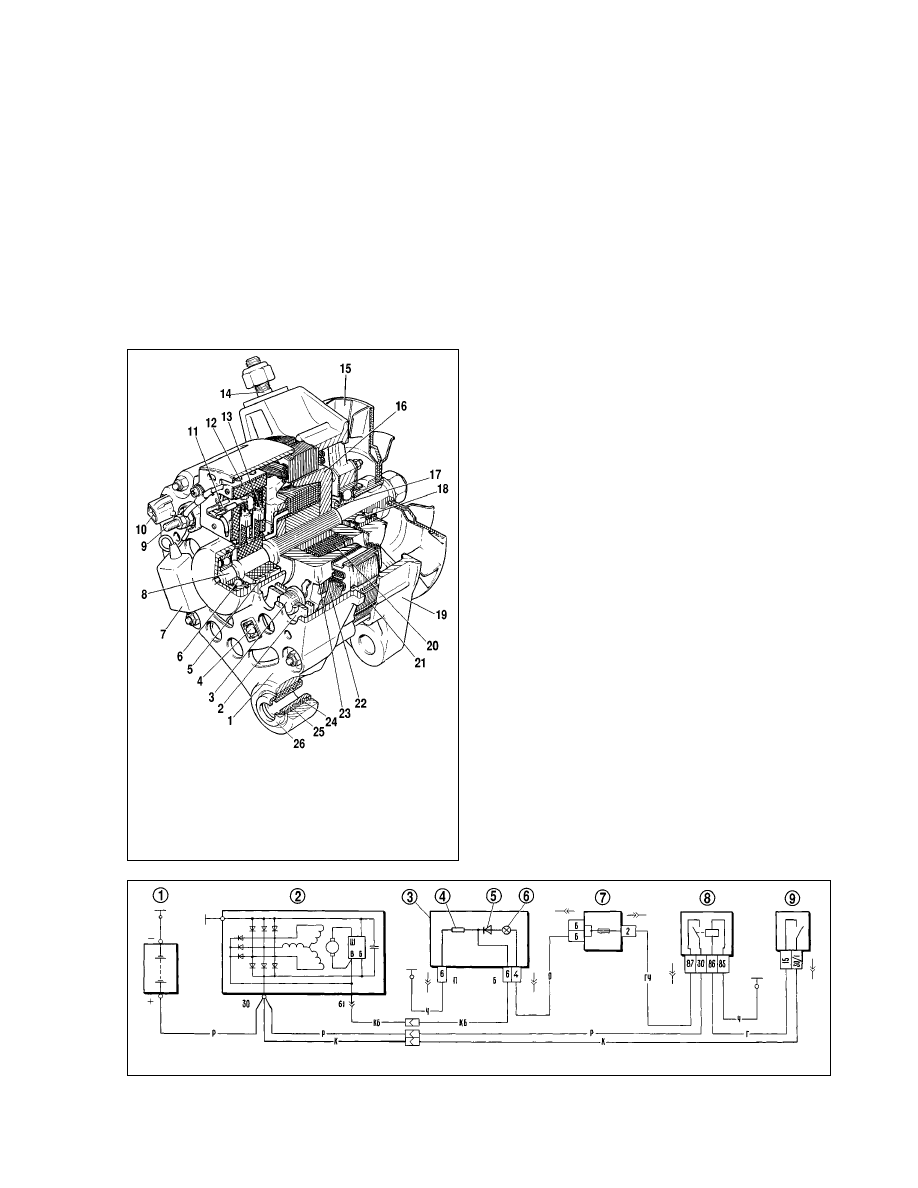
Fig.7-1. Electrical system of VAZ-21213 vehicle:
1 - left-hand front headlamp; 2 - headlights; 3 - left-hand headlamp wiper motor; 4 - horn; 5 - fuel cutoff solenoid; 6 - idle switch; 7 - headlight washer motor; 8 - right-hand
headlight wiper motor; 9 - right-hand front headlamp; 10 - side repeaters; 11 - battery; 12 - heater motor; 13 - heater motor complimentary resistor; 14 - differential lockup
warning light switch; 15 - windscreen wiper relay; 16 - starter motor; 17 - windscreen wiper motor; 18 - alternator; 19 - windscreen washer motor; 20 - fuel cutoff solenoid
control unit; 21 - spark plugs; 22 - ignition distributor; 23 - spark control module; 24 - ignition coil; 25 - temperature gauge sender unit; 26 - oil pressure warning light sender;
27 - inspection lamp socket; 28 - brake fluid level warning light switch; 29 - headlight wipe/wash relay; 30 - rear window heating relay; 31 - main beam relay; 32 - dipped
beam relay; 33 - ignition switch relay; 34 - starter motor relay; 35 - complimentary fuse box; 36 - main fuse box; 37 - indicators flasher relay; 38 - reversing light switch; 39
137
- stop light switch; 40 - cigarette lighter; 41 - exterior light switch; 42 - heater controls illumination; 43 - rear fog light switch; 44 - rear window heating switch; 45 - heater
motor switch; 46 - rear window wipe/wash switch; 47 - hazard warning flasher switch; 48 - ignition switch; 49 - instrument lighting switch; 50 - windscreen wiper switch; 51
- switch, windscreen washer & headlamp wipe/wash; 52 - horn switch; 53 - direction indicator switch; 54 - headlight switch; 55 - choke warning light switch;
56 - choke warning light; 57 - door courtesy light switches; 58 - interior lights; 59 - rear window washer motor; 60 - instrument cluster; 61 - handbrake warning light switch;
62 - fuel level and fuel reserve gauge sender unit; 63 - rear lights; 64 - number plate light; 65 - rear window wiper motor; 66 - rear window heating element;
Ä - pin assignment in steering column combination switch connector
Battery
Specification
Battery . . . . . . . . . . . . . . . . . . . . . . . . . . 6ëí-55Ä, maintenance-free
Maximum voltage,volt . . . . . . . . . . . . . . . . . . . . . . . . . . . . . . . . . . 12
Maximum capacity (at 20-hour
discharge rate and initial electrolyte
temperature of (27±2)°ë, ampere-hour . . . . . . . . . . . . . . . . . . . . . 55
20-hour discharge amps rate . . . . . . . . . . . . . . . . . . . . . . . . . . . 2.75
Cold start amps rating (with running starter motor
and electrolyte temperature of -18°ë) . . . . . . . . . . . . . . . . . . . . . . 255
Fault diagnosis
Cause
Remedy
Battery discharge in operation
1. Alternator drivebelt slipping
2. Battery surface dirty
3. Damaged insulation in electrical
equipment system (discharge rate
exceeds 11 mÄ with loads discon-
nected)
4. Too many accessories fitted by
vehicle owner
5. Alternator faulty
6. Electrolyte contaminated
7. Short-circuits between plates
8. Electrolyte level below top plate
edge
Electrolyte on battery cover
1. Too high electrolyte level caus-
ing spillage
2. Electrolyte leaks through frac-
tures in battery case
3. Electrolyte boiling due to
excessive alternator voltage
4. Electrolyte boiling through plate
sulfation
Dry-storage battery - putting into operation
The vehicles are factory-fitted with ready-to-use batteries, i.e.
batteries filled with electrolyte and fully charged.
Replacement batteries can be supplied dry, without elec-
trolyte. In order to operate such battery, first remove any provi-
sional plugs or masking tape. Then using a funnel (made of glass
or acid-resistant plastic), slowly fill the battery with electrolyte (at
25°ë) of 1.28 g/cm
3
for normal climates or 1.23 g/cm
3
for tropics.
All procedures required to activate the battery should be per-
formed at the ambient temperature of (25±10)°ë.
Allow 20 minutes for the internal plates and separators to sat-
urate well in electrolyte. Then check the battery voltage without
loads.
The battery is ready for use when its voltage reading is at
least 12.5 volts. At values below 12.5 volts but over 10.5 volts, the
battery should be recharged to the output voltage which is spec-
ified by the manufacturer. The battery is rejected when the volt-
age is equal or below 10.5 volts.
The saturation of internal plates and separators normally
results in a lower electrolyte level. Therefore, top up the battery
with electrolyte of the original specific gravity before refitting it to
the vehicle.
Always re-charge the battery after it is filled with electrolyte in
the event:
- the battery will be initially operated in heavy duty conditions,
in cold weather, at frequent engine starts, etc.;
- the battery has been stored for over 12 months from the
date of manufacture.
Electrolyte level - checking
Electrolyte level in all battery cells must be maintained
between the «MIN» «MAX» marks on the translucent battery
case. Never try to use the battery with the electrolyte level below
the «MIN» mark.
In the course of vehicle operation the electrolyte level gradu-
ally decreases due to water evaporation. Only distilled water
should be used to top up the battery.
If spillage is suspected to be the cause for low electrolyte
level, always add electrolyte of the same specific gravity as that
remaining in the battery cell. When overfilled, remove excessive
electrolyte using an ebony-tipped rubber bulb.
Battery charge level- checking
Always measure the battery charge with a hydrometer (are-
ometer) during servicing or in the event of the battery failed in
operation. At the same time measure the temperature in order to
account for temperature correlation (Table 7-3) of hydrometer
readings.
138
Fig.7-2. Fuses
1. Adjust belt tension
2. Clean battery surface
3. Locate battery leak and remedy
the situation
4. Disconnect new electrical con-
sumers
5. Check alternator
6. Charge battery, drain electrolyte,
flush, fill with new electrolyte and
recharge battery
7. Renew battery
8. Restore electrolyte level
1. Replenish electrolyte as required
2. Replace battery
3. Replace alternator
4. Replace battery
Table 7-3
Temperature correction values to hydrometer readings
for measuring electrolyte density
Electrolyte temperature, °ë
Correction value, g/cm
3
-40 to -26
-0.04
-25 to -11
-0.03
-10 to +4
-0.02
+5 to +19
-0.01
+20 to +30
0.00
+31 to +45
+0.01
With electrolyte temperatures over 30°ë, the correction value
is added to actual hydrometer readings. When electrolyte tem-
perature is below 20°ë, the correction value is subtracted. The
correction value is not applied when electrolyte temperature is
within 20 to 30°ë.
Once you have measured the electrolyte specific gravity in
each battery cell, determine the state of the battery charge using
Table 7-4. Withdraw the battery from the vehicle for re-charging
when it is discharged in excess of 25 percent in winter time or 50
percent in summer time.
When measuring electrolyte density, take care not to drip
electrolyte on the battery cover, case, body or other parts.
Electrolyte contains hazardous sulfuric acid which causes corro-
sion, current leaks, etc.
Do not measure the electrolyte specific gravity in the follow-
ing cases to exclude wrong readings:
- when the electrolyte level is not as required;
- when electrolyte is too hot or too cold; the optimum temper-
ature to measure electrolyte specific gravity is 15-27°ë;
- immediately after the battery replenishment. Leave the bat-
tery for some time to let the electrolyte mix up; it may take up to
several hours if the battery has been fully discharged;
- after a number of start-up attempts. It is advisable to wait
until electrolyte in the battery cell is homogeneous in terms of
density;
- when electrolyte is «boiling». Wait to see bubbles rising to
the surface in the electrolyte, sampled with a hydrometer.
Battery charging
Remove the battery from the vehicle and clean it carefully,
especially its top. Check the electrolyte level and replenish, if
applicable.
The battery is recharged at a rate of 5.5 amperes with the
caps undone. Charge the battery until intensive gas escape is
observed and consistent voltage and electrolyte specific gravity is
achieved within three hours. The electrolyte density of the
charged battery at 25°ë should be as shown in Table 7-4.
When recharging the battery, frequently check the electrolyte
temperature to keep it below 40°ë. When 40°ë is reached, then
either halve the charging current or stop recharging to cool the
battery down to 27°ë.
Stop charging the battery in case of intensive gas escape
from the battery cells and when the last three measurements
(taken hourly) show no changes in voltage and specific gravity.
If at the end of the recharging procedure the electrolyte spe-
cific gravity (after temperature correlation) differs from that spec-
ified, adjust it accordingly. In case of higher specific gravity,
remove some electrolyte and top up distilled water, while in case
of lower specific gravity - remove some amount of lower specific
gravity electrolyte and add some higher specific gravity elec-
trolyte (1.4 g/cm
3
).
After the electrolyte specific gravity has been duly adjusted,
continue to charge the battery further 30 minutes for better elec-
trolyte mixing. Next disconnect the battery and after 30 minutes
check the electrolyte level in all cells.
When electrolyte is below the level required, pour in elec-
trolyte of the specific gravity which is recommended for that cli-
mate (Refer to Table 7-4). When electrolyte level is above that
required, remove excessive amount using a rubber bulb.
139
Table 7-4
Electrolyte specific gravity at 25°ë, g/cm
3
Climate (average
Season
Fully discharged
Battery discharged
January temperature, °ë
battery
by 25%
by 50%
Very cold (from -50 to -30)
Winter
1.30
1.26
1.22
Summer
1.28
1.24
1.20
Cold (from -30 to -15)
All seasons
1.28
1.24
1.20
Moderate (from -15 to -8)
All seasons
1.28
1.24
1.20
Warm and damp (from 0 to +4)
All seasons
1.23
1.19
1.15
Hot and dry (from -15 to +4)
All seasons
1.23
1.19
1.15
Alternator
Specification
Maximum current output (at 13 volts and 5000 rpm ), amp . . 55
Adjustable voltage range, volts . . . . . . . . . . . . . . . . . . 14.1±0.5
Maximum rotor speed, rpm . . . . . . . . . . . . . . . . . . . . . . 13,000
Engine-to-alternator ratio . . . . . . . . . . . . . . . . . . . . . . . . 1:2.04
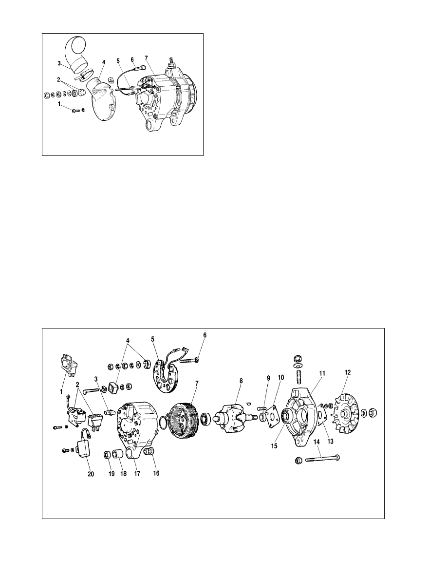
General description
The alternator of 37.3701 model is of AC, three-phase, clock-
wise rotation (when viewed from the drive end), with integral
diode plate and voltage regulator.
Protective cover 4 is used for slip ring-end housing (Fig.7-11).
The protective cover and air intake have several design alterna-
tives.
Four bolts hold together stator 21 (Fig.7-3) and housings 1
and 19. Rotor shaft 8 runs in bearings 6 and 18 located in the
housings. The rotor winding (field winding) is powered through
the brushes and slip rings 5.
Three-phase alternative current, induced in the stator wind-
ing, is converted into direct current in diode plate 2 fitted to hous-
ing 1. Electronic voltage regulator 12 is integral with the brush
holder and is also attached to housing 1.
The alternator wiring diagram is shown in Fig.7-4. When the
ignition is switched on, the voltage for the alternator actuation is
applied to the regulator terminal «Ç» (alternator terminal 61) via
warning light 6 in instrument cluster 3. Once the engine is start-
ed, the current to the field winding is supplied from three supple-
mentary diodes in the alternator diode plate.
The alternator operation is checked via warning light 6 in the
instrument cluster. The light comes on when the ignition is
switched on and goes out after the engine has been started,
when the alternator is good. Bright or dim light of the warning
lamp indicates faults.
Before 1995 an electronic voltmeter in the instrument cluster
was used to control voltage in the vehicle electrical system. With
correct voltage the voltmeter LED did not light up. In case of over-
voltage the LED started flashing, while in case of undervoltage
the LED stayed steadily.
Starting from 1996 an alternative voltage regulator and brush
holder are used. Now the voltage regulator is located in the metal
housing and is riveted to the brush holder (Fig.7-10, ‡), making a
unit. The new voltage regulator has no terminal «Å», so voltage
is supplied only to terminal «Ç». Both the earlier and new voltage
regulators are similar and are interchangeable as a complete unit
with the brush holder.
Some vehicles can be fitted with alternators made in
Slovenia, Bulgaria or Germany. These alternators are inter-
changeable with the alternator of 37.3701 model as to specifica-
tion and mounting sizes, though are slightly different in design.
This chapter describes the alternator of 37.3701 model, prefer-
ably used in VAZ-21213 vehicles.
140
Fig.7-4. Alternator wiring diagram:
1 - battery; 2 - alternator; 3 - instrument cluster; 4 - resistor 51 Ohm, 5 W; 5 - diode; 6 - low battery charge warning light; 7 - fuse box; 8 - ignition relay; 9 - ignition switch
Fig.7-3. Alternator 37.3701:
1 - slip ring end housing; 2 - diode plate; 3 - diode; 4 - screw; 5 - slip ring; 6 -
rear ballbearing; 7 - suppression condenser; 8 - rotor shaft; 9 - alternator termi-
nal «30»; 10 - alternator terminal «61»; 11 - voltage regulator terminal «Ç»; 12
- voltage regulator; 13 - brush; 14 - alternator-to-belt tensioner lever securing
pin; 15 - pulley and fan; 16 - rotor pole end; 17 - spacer; 18 - front ballbearing;
19 - drive-end housing; 20 - rotor winding; 21 - stator; 22 - stator winding; 23 -
rotor pole end; 24 - buffer bush; 25 - bush; 26 - hold-down bush

Fault diagnosis
Cause
Remedy
Warning light does not light up when ignition is switched on.
Instruments inoperative
1. Blown fuse 2 in fuse box
2. Broken supply circuit in instru-
ment cluster:
- no voltage between terminal «Å»
of main fusebox and instrument
cluster;
- no voltage between ignition relay
and fusebox unit
3. Ignition switch or ignition relay
faulty:
- faulty contact part or ignition
relay;
- no voltage between ignition
switch and ignition relay;
- break or no contact in the igni-
tion relay earth wire
Warning light does not light up when ignition is switched on and
does not stay on during engine operation.
Instruments operate. Battery is discharged.
1. Blown warning light bulb or
loose holder-to-PCB contact
2. Broken circuit between instru-
ment cluster and alternator termi-
nal 61
3. Brushes worn or binding, slip
ring oxidized
4. Voltage regulator damaged
(break between «ò» terminal
and earth)
5. Lead from voltage regulator
«Ç» terminal disconnected
6. Short-circuit in positive diodes
7. Field winding leads discon-
nected from slip rings
8. No contact between voltage
regulator terminals «Ç» and «ò»
and brush terminals (for pre-1996
alternators)
Warning light is bright or half bright with engine running. Battery
is non-charged
1. Alternator drivebelt slipping
2. Voltage regulator damaged
3. Damaged diodes
4. Field winding diodes damaged
5. Stator winding broken, shorted
or earthed
Warning light is on with engine running. Battery is overcharged
Voltage regulator damaged (short-
circuit between terminal «ò» and
earth)
Alternator is noisy
1. Loose alternator pulley nut
2. Alternator bearings damaged
3. Stator winding shorted internally
or to housing (alternator howl)
4. Short-circuit in diode plate
5. Brush squeak
WARNING. Always earth the battery negative post to the
bodyshell and connect the positive post to the alternator clip
30. If battery connections are erroneously reversed, the
alternator diodes will be damaged by resulting high voltage.
Never operate the alternator with the battery disconnect-
ed since this causes overvoltage peaks at the alternator ter-
minal 30 and can damage the voltage regulator or other elec-
tronic devices of the vehicle electrical system.
Never test the alternator for «spark» by earthing the
alternator terminal 30 even for a short time. The diodes can
be damaged by considerable current flow. Check the alter-
nator operation using an ammeter or a voltmeter.
Never check the alternator diodes by applying voltage
over 12 volts or using a megohmmeter, as its voltage is very
high and can damage the diodes (by short-circuit).
Never check the vehicle wiring by a megohmmeter or a
lamp powered in excess of 12 volts. If the check is really
necessary, disconnect the leads from the alternator first.
Always use the test bench and disconnect the winding
from the diodes when performing the high voltage check of
alternator stator winding insulation resistance.
When welding the body units or components, remember
to disconnect first the leads from all battery and alternator
connectors.
Alternator - testing
Using tester
A tester helps determine whether the alternator is faulty or
meets the specification. The carbon brushes of the unit tested
should slide smoothly on the slip rings, which should always be
clean.
141
1. Renew fuse
2. Carry out the following:
- check wire «é» and its connec-
tions between fuse boxes and
instrument cluster;
- check wire «Éó» and its connec-
tions between ignition relay and
fusebox
3. Carry out the following:
- check and renew faulty contact
part of ignition switch or ignition
relay;
- check wire «É» and its connec-
tions between ignition switch and
ignition relay;
- check wire «ó» and its connec-
tions between ignition relay and
earth
1. Renew failed bulb, bend holder
contacts or replace bulb holder
2. Check wire «äÅ» and its connec-
tions between alternator and instru-
ment cluster
3. Renew brush holder with brush-
es, clean slip rings with fuel-moist-
ened cloth
4. Renew voltage regulator
5. Reconnect wire
6. Renew diode plate
7. Solder pins or renew alternator
rotor
8. Clean voltage regulator terminals
«Ç», «ò» and brush output; bend
voltage regulator pins
1. Adjust belt tension
2. Renew voltage regulator
3. Renew diode plate
4. Renew diodes or diode plate
5. Replace alternator stator
Renew voltage regulator
1. Tighten nut
2. Renew rear bearing or front
cover with bearing
3. Renew stator
4. Renew diode plate
5. Clean brushes and slip rings with
cotton cloth moistened in petrol
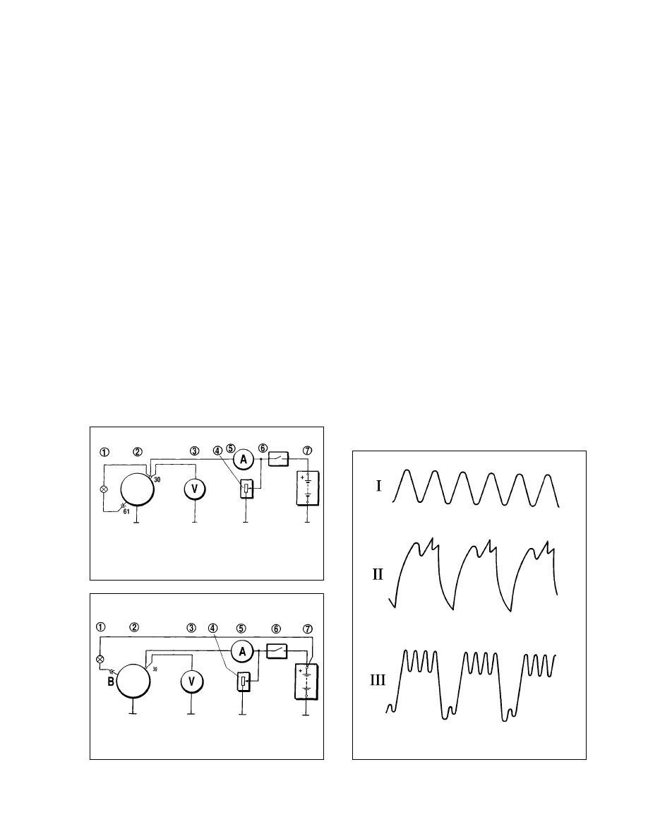
Mount the alternator on the tester and connect as shown in
Fig.7-5. Start the tester motor, using rheostat 4, set the alternator
output voltage at 13 volts and raise the rotor speed to 5000 rpm.
Run the alternator at this speed for at least 10 minutes and then
measure the alternator output amperage. The reading for a sound
alternator should not be below 55 amperes.
When the measured amperage is much lower, this is an indi-
cation of some fault in the stator or rotor windings or damaged
diodes. If this is the case, very thorough diagnostics will have to
be carried out in order to locate the fault.
The output voltage should be measured at rotor speed of
5000 rpm. Set rheostat 4 to test amperage of 15 amps and take
the reading of the alternator output voltage to be within 14.1±0.5
volts at the ambient / alternator temperature of 25±10°ë.
If the voltage reading falls outside the range specified, replace
the complete voltage regulator with a new unit which is proved
good. Then repeat the test procedure. Normal voltage indicates
that the old regulator is faulty and must be renewed. If the fault per-
sists, check the alternator windings and diodes.
Alternator - oscilloscope test
The oscilloscope offers an accurate and quick way to check
the alternator and identify the fault through the output waveform.
To perform the check make the connections as shown in
Fig.7-6. Disconnect the output lead common for three supple-
mentary diodes from the voltage regulator terminal «Ç» and make
sure the lead end does not touch the alternator housing. Connect
the battery lead to the regulator terminal «Ç» via warning light 1.
Now the field winding is only battery powered.
Start the tester motor and increase the rotor speed up to
1500-2000 rpm. Using switch 6, cut off the battery from the alter-
nator terminal 30; while using rheostat 4, set the output current at
10 amperes.
Check the voltage across the alternator terminal 30. When
the diodes and stator winding are sound, the output waveform is
«saw-shaped» with uniform peaks (Refer to Fig.7-7, I). In case of
a broken stator winding or shorted diodes, the waveform is quite
different - the peaks are no longer uniform and there are very
deep troughs (Fig.7-7, II Ë III).
Check to see the output waveform across the alternator ter-
minal 30 is normal; next check voltage across the alternator ter-
minal 61 or at the end of the lead disconnected from the voltage
regulator terminal «B». These points are a common connection
for three supplementary diodes (Fig.7-4), supplying current to the
field winding during the alternator operation. The output wave-
form must have the same even saw-shaped pattern. An irregular
waveform is an indication of damaged supplementary diodes.
Rotor field winding - testing
The field winding can be tested with the alternator in the vehi-
cle. It is sufficient to remove the housing and voltage
regulator/brush holder assembly.
142
Fig.7-5. Wiring connections for diode plate test:
1 - warning light (12 v, 3 W); 2 - alternator; 3 - voltmeter; 4 - rheostat;
5 - amperemeter; 6 - switch; 7 - battery
Fig.7-6. Alternator wiring connections for oscilloscope test:
1 - warning light (12 v, 3 W); 2 - alternator; 3 - voltmeter; 4 - rheostat;
5 - amperemeter; 6 - switch; 7 - battery
Fig.7-7. Alternator rectified waveform:
I - sound alternator; II - blown diode; III - diode circuit broken (stator winding)
When necessary, sand the slip rings with emery paper, then
check the winding for continuity or earthing with an ohmmeter or
a test bulb.
Stator - testing
The stator is tested separately after dismantling the alterna-
tor and disconnecting the winding from the diodes.
First test the stator winding for continuity or earthing using an
ohmmeter or a test bulb and battery. The wire insulation should
show no signs of overheating caused by short-circuit in the diode
plate. Always renew the stator with a damaged winding.
Finally, using a special growler, check the stator winding for
internal short-circuit.
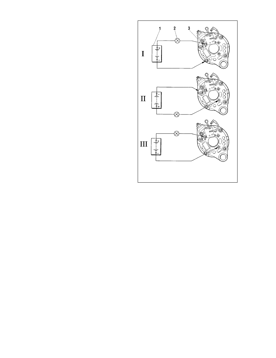
Diodes - testing
A sound diode allows current only in one direction. A faulty
diode can either prohibit the current flow (a broken circuit) or
allow it in both directions (a short-circuit).
The complete diode plate must be renewed if any diode is
found damaged.
The diode plate can be checked for a short-circuit with the
alternator in the vehicle. For this disconnect leads from the bat-
tery and alternator and remove the slip ring end housing. Also the
lead to the voltage regulator terminal «Ç» should be disconnect-
ed. In case of the alternator with an old voltage regulator do not
forget to disconnect the voltage regulator terminal «Å» from the
alternator terminal 30.
An ohmmeter or a test bulb (1-5 watt, 12 volts) and battery can
be used as shown in Fig.7-8.
Note. For easier diode fitting three diodes (marked red) make
«positive» rectified voltage. These diodes are «plus» and are
pressed within one diode plate connected to the alternator termi-
nal 30. Three other diodes («minus», marked black) have «neg-
ative» rectified voltage to the housing. They are press-fitted to the
other diode plate connected to earth.
First make sure both positive and negative diodes are not
shorted internally. For this connect the battery positive terminal
through a test bulb to the alternator terminal 30, whilst the nega-
tive terminal - to the alternator housing (Fig.7-8, I). The illuminat-
ed bulb indicates shorted positive and negative diodes.
Short-circuit in the negative diodes can be detected by con-
necting the battery «plus» terminal through a test bulb to one of
the diode plate securing bolts, while the «minus» to the alterna-
tor housing (Fig.7-8, II). The illuminated bulb is an indication of a
short-circuit fault in one or more negative diodes. Note that in the
latter case the bulb may come on as a result of stator winding
being earthed to the alternator housing. However, this fault is
much less frequent than short-circuits in the diodes.
Short-circuit in the positive diodes can be detected by con-
necting the battery «plus» terminal through a test bulb to the
alternator terminal 30, while «minus» - to one of the diode plate
securing bolts (Fig.7-8, III). The illuminated bulb advises about a
short-circuit in one or more positive diodes.
Discontinuity in the diodes can be traced without dismantling
the alternator either by means of an oscilloscope or a tester
through a significant output current drop (20 to 30 percent)
against the specification. If the alternator windings, supplemen-
tary diodes or voltage regulator are sound, whilst the diodes are
not shorted, the cause of the output current drop is discontinuity
in the diodes.
Supplementary diodes - testing
To check the supplementary diodes for short-circuit without
removing and dismantling the alternator, make connections as
shown in Fig.7-9. Similarly to the diode checking, disconnect the
battery and alternator leads, remove the alternator housing, dis-
connect the lead to the voltage regulator terminal «Ç».
Connect the battery positive post through a test bulb (1-3
watt, 12 volts) to the alternator terminal 61, while the negative
post - to one of the diode plate securing bolts.
143
Fig.7-8. Diode check:
1 - battery; 2 - warning light; 3 - alternator; I - concurrent check of positive and
negative diodes; II - check of negative diodes; III - check of positive diodes
An illuminated bulb advises about short-circuit in one or more
supplementary diodes.
The damaged diode can be identified only after removing the
diode plate and checking each diode.
Discontinuity in the supplementary diodes can be detected
with an oscilloscope through distortions in the voltage waveform
across terminal 61 and also by low voltage (below 14 volts) across
terminal 61 at a medium rate of the alternator rotor.
Voltage regulator - testing
The function of the voltage regulator is to continuously adjust
the field current flow to the alternator so that the alternator volt-
age is maintained within the preset range at various speed / load
conditions of the alternator operation.
In-vehicle test. For this test you need a DC voltmeter with
15-30 volt scale and accuracy of at least 1.0 class.
Run the engine for 15 minutes at medium speeds with the
headlights on, measure the voltage between the alternator termi-
nal 30 and alternator earth. The reading should be within 13.6-
14.6 volts.
When battery undercharge or overcharge becomes repeti-
tive, while the adjustable voltage falls outside the specification,
the voltage regulator must be renewed.
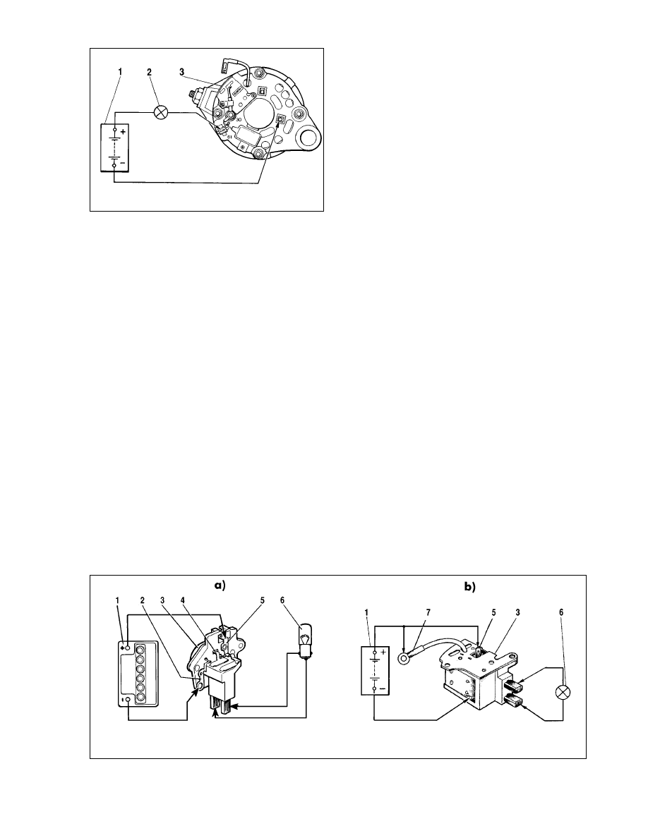
Off-vehicle test. For testing the voltage regulator, removed
from the alternator, make the connections as shown in Fig.7-10.
The pre-1996 voltage regulator should be tested complete with
the brush holder (Fig.7-10, b), since at the same time you can
detect a broken brush connection or a poor contact between the
voltage regulator terminals and brush holder.
Connect a test lamp of 1-3 watt, 12 volts across the brush ter-
minals. The terminals «Ç», «Å» (when available) and earth ter-
minal should be connected first to the power supply of 12 volts
and then to that of 15-16 volts.
With the sound voltage regulator, the lamp illuminates in the
first case and goes out in the second case. If the lamp illuminates
in both cases, there must be a break in the voltage regulator; when
the bulb fails to light in both cases, the regulator circuit is broken or
brush-to-regulator connection is loose (for pre-1996 alternators).
Capacitor - testing
The suppression capacitor is intended to protect the on-
board electronic equipment against voltage surges in the ignition
system along with suppression of radio interference.
A damaged capacitor or its loose fitting to the alternator (poor
ground) is recognizable through increased radio interference with
the engine running.
A simple way of testing the capacitor is to use a megohm-
meter or a tester (scaled as 1-10 åéhm). In case of a sound
capacitor, when its contacts are closed via the instrument, the
needle should first deflect towards a lower resistance values and
then gradually return to the initial position. The capacitance mea-
sured with a special device should be 2.2 microfarad ± 20%.
Alternator - overhaul
Alternatzor - dismantling
Clean the alternator and blow dry with compressed air.
Release the clip to disconnect air intake 3 (Fig.7-11) from hous-
ing 4. Undo two screws 1 and nut from contact bolt extension 5,
144
Fig.7-10. Checking the voltage regulator:
a - 1996-on voltage regulator; b - pre-1996 voltage regulator; 1 - battery; 2 - voltage regulator earth ; 3 - voltage regulator; 4 - voltage regulator terminal «ò»; 5 - voltage
regulator terminal «B»; 6 - warning light; 7 - voltage regulator terminal «Å»
Fig.7-9. Checking the supplementary diodes:
1 - battery; 2 - warning light; 3 - alternator
remove housing 4. Disconnect lead 6 from alternator terminal 61
and undo contact bolt extension 5.
Lock the alternator pulley with a tool from kit 67.7823.9504,
undo the pulley retaining nut and press the pulley out using a
puller.
Remove the pulley key and taper washer.
Tool kit 67.7823.9504 includes an ordinary picker and a grip.
The grip consists of two steel half-rings, inserted into the pulley.
The half-rings are of the same cross-section area as the
alternator drivebelt. At one end they are connected by means of
the joint, at the other end they have levers to be compressed by
hand when removing the pulley.
Disconnect the wire from the alternator terminal «B».
Disconnect the voltage regulator and capacitor leads from alter-
nator terminal 30, undo regulator 1 retaining screws (Fig.7-12)
and withdraw it. In case of pre-1996 alternators to prevent dam-
ages to the brushes when removing the brush holder. Insert a
screwdriver between regulator 2 housing and brush holder, then
partly pull out the regulator from the alternator, leaving the brush
holder in place. Next swing and withdraw the regulator complete
with the brush holder from the alternator. Undo the retaining
screw and remove suppression capacitor 20.
Undo clamp bolt 14 nuts, remove alternator housing 11 and
rotor 8. Undo the bolt nuts, connecting diode ends to stator wind-
ing terminals, withdraw stator 7 from alternator housing 17.
Undo contact bolt 6 nut, disconnect the supplementary diode
wire terminal from connector 3, remove diode plate 5.
Alternator - reassembly
The reassembly of the alternator is the reverse of the dis-
mantling procedure.
In case of pre-1996 alternators (with detachable regulator /
brush holder unit), in order to avoid damage to the brushes,
before refitting the regulator complete with the brush holders, do
not fully insert the brush holder into the regulator, it should be
pushed in place only partly, then insert the assembly as such into
the alternator. After the brush holder is refit into the alternator
housing, press lightly the regulator into the alternator.
Out-of-concentricity for the holes in the alternator housings
must not exceed 0.4 mm. Therefore during reassembly always
insert a special gauge into these holes.
The taper spring washer of the pulley must be assembled
with the convex side facing the nut. Tighten the pulley securing
nut to a torque of 38.4-88 N•Ï (3.9-9.0 kgf•m)
145
Fig.7-11. Removing the alternator protective case:
1 - securing screw; 2 - bushes; 3 - air intake; 4 - protective case; 5 - extension,
alternator terminal 30; 6 - wire, alternator terminal 61; 7 - alternator
Fig.7-12. Alternator components:
1 - voltage regulator complete with brush holder, 1996-on alternators; 2 - voltage regulator and brush holder, pre-1996 alternators; 3 - supplementary diode connector; 4
- insulating bushes; 5 - diode plate; 6 - contact bolt; 7 - stator; 8 - rotor; 9 - spacer; 10 - inner washer for bearing attachment; 11 - drive end housing; 12 - pulley; 13 - outer
washer for bearing attachment; 14 - clamp bolt; 15 - front rotor ball bearing; 16 - bush; 17 - slip ring end housing; 18 - buffer bush; 19 - hold-down bush; 20 - suppression
capacitor

Brush holder - renewal
Always renew the complete unit if the regulator fails or brush-
es are worn or protrude from the holder to less than 5 mm.
In case of pre-1996 alternators, force the brush holder out of
the voltage regulator housing by pressing the terminal «Ç». Avoid
damaging the brushes, so remove and refit the regulator with the
brush holder as described earlier in sections «Alternator - dis-
mantling» and «Alternator - reassembly».
In case of 1996-on alternators with one-piece regulator/brush
holder unit, renew the complete brush regulator/holder assembly.
Before refitting the voltage regulator with new brush holder,
blow its locating place in the alternator clean from carbon dust
and wipe off any oil contamination.
Rotor bearings - renewal
To remove a failed bearing from the drive-end housing, undo
the nuts of screws holding the bearing retaining washers, remove
the washers and screws, then press out the bearing on a hand
press. Should the screw nuts fail to undo (the screw ends are
bent-up), cut off the screw ends.
Refit the new bearing to the alternator housing only when the
bore for the bearing is not deformed and its diameter is not over
42 mm. If the bore is bigger or deformed, renew the housing.
Using a press, drive in the bearing, then compress the bear-
ing between two washers, held by the screws and nuts. Tighten
the nuts and bend-up the screw ends. The slip ring rotor bearing
is renewed together with the housing, since when the bearing is
damaged, the recess in the housing is damaged too. The bearing
is removed from the rotor using a puller; use a press tool to drive
it into position.
Supplementary diodes - renewal
To replace a damaged diode, unsolder its pins, then careful-
ly take the diode out from the plastic holder, taking care not to hit
the diode plate. Clean the holder from epoxy, fit a new diode and
solder it.
The colour-coded diode terminal must be re-soldered to the
common output wire. After soldering, secure the diode to the
holder with epoxy.
Starter motor
Specification
Maximum power, kW . . . . . . . . . . . . . . . . . . . . . . . . . . . . .1.3
Amperage at maximum power, not greater . . . . . . . . .290±10
Amperage at ‘brake-on’, not greater . . . . . . . . . . . . . . . . . 550
Amperage at idle without solenoid, not greater . . . . . . . . . . .60
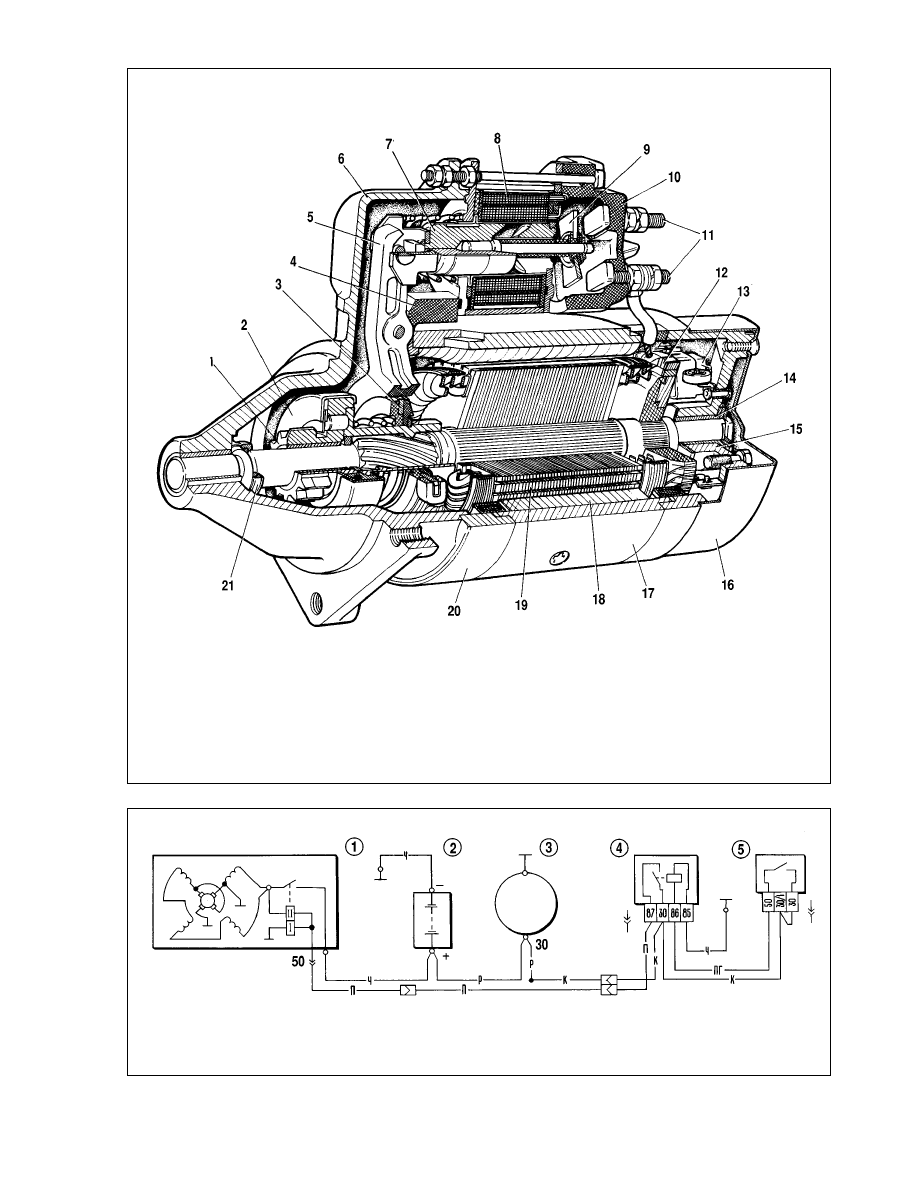
General description
The starter motor is of pre-engaged type (35.3708 model),
DC, with field coils, incorporating a double-winding solenoid.
Body 17 (Fig.7-13) houses four poles 18 with field windings,
three of which are series and one is parallel. Covers 7 and 15 and
starter housing 17 are held together by two bolts. The armature
features a face-type commutator. The armature shaft runs in sin-
tered shells 14, press fitted to cover 6 and 15.
The starter motor wiring diagram is shown in Fig.7-14. When
the starter motor is switched on, the battery voltage is supplied
through supplementary relay 4 (113.3747-10 model) to both sole-
noid windings (plunging winding II and holding winding I). The
plunging winding shuts off when the solenoid contacts close.
Fault diagnosis
Cause
Remedy
At starter motor switch-on, armature fails to rotate,
solenoid inoperative
1. Battery defective or fully dis-
charged
2. Battery terminal posts and lead
ends severely corroded; end loose
3. Solenoid faulty internally, earth-
ed or broken
4. Starter motor relay defective
5. Starter relay winding power cir-
cuit open
6. Ignition switch contacts 30 and
50 fail to close
7. Starter solenoid power leads
broken
8. Stuck starter solenoid
No or slow armature rotation, solenoid inoperative
1. Battery defective or fully dis-
charged
2. Battery posts and lead clamps
severely corroded; ends loose
3. Loose end of cable from power
plant to body or between power
plant to battery «minus» post
4. Solenoid terminal bolts oxidized
or terminal bolt wire end retaining
nuts loose
5. Commutator burnt, brushes
sticking or worn
6. Stator winding or armature bro-
ken or shorted
7. Positive brush holder earthed
146
1. Renew or charge battery
2. Clean battery posts and wire
ends, tighten and apply a coat of
petroleum jelly
3. Tighten cable end fasteners
4. Clean terminal bolts, tighten lead
retaining nuts
5. Clean commutator, renew brush-
es
6. Renew stator or armature
7. Eliminate shock-circuit or renew
commutator end cover
1. Charge or renew battery
2. Clean battery posts and lead
ends, tighten and apply a coat of
petroleum jelly (Vaseline)
3. Renew solenoid
4. Clean relay contacts. Renew
faulty relay
5. Check wires and connections
between ignition switch terminal 50
and relay terminal 86
6. Renew ignition switch contact
unit
7. Check leads and connections:
battery - starter cut-in relay -
starter solenoid terminal 50
8. Remove solenoid, check arma-
ture for smooth slide

Solenoid repetitive cutting in and out
1. Battery discharged
2. Excessive voltage drop in sole-
noid power circuit caused by
badly oxidized lead ends
3. Solenoid holding winding bro-
ken or shorted
Starter motor armature rotates, flywheel inoperative
1. Overrun clutch slipping
2. Clutch operating lever broken
or pivot shaft dropped
3. One-way clutch guide ring or
buffer spring broken
Starter motor noisy
1. Starter motor retaining nuts
loose or drive-end housing broken
2. Starter wrongly mounted
3. Bearing shells or armature shaft
journals excessively worn
4. Stator pole loose (armature
touches pole)
5. Pinion or ring gear teeth dam-
aged
6. Pinion fails to disengage ring
gear:
- operating lever seized;
- overrun clutch jams in mesh with
armature shaft splines;
- clutch or solenoid springs loose
or broken;
- clutch hub circlip lost;
- solenoid armature sticking;
- ignition switch contact part faulty:
pins 30 and 50 fail to open
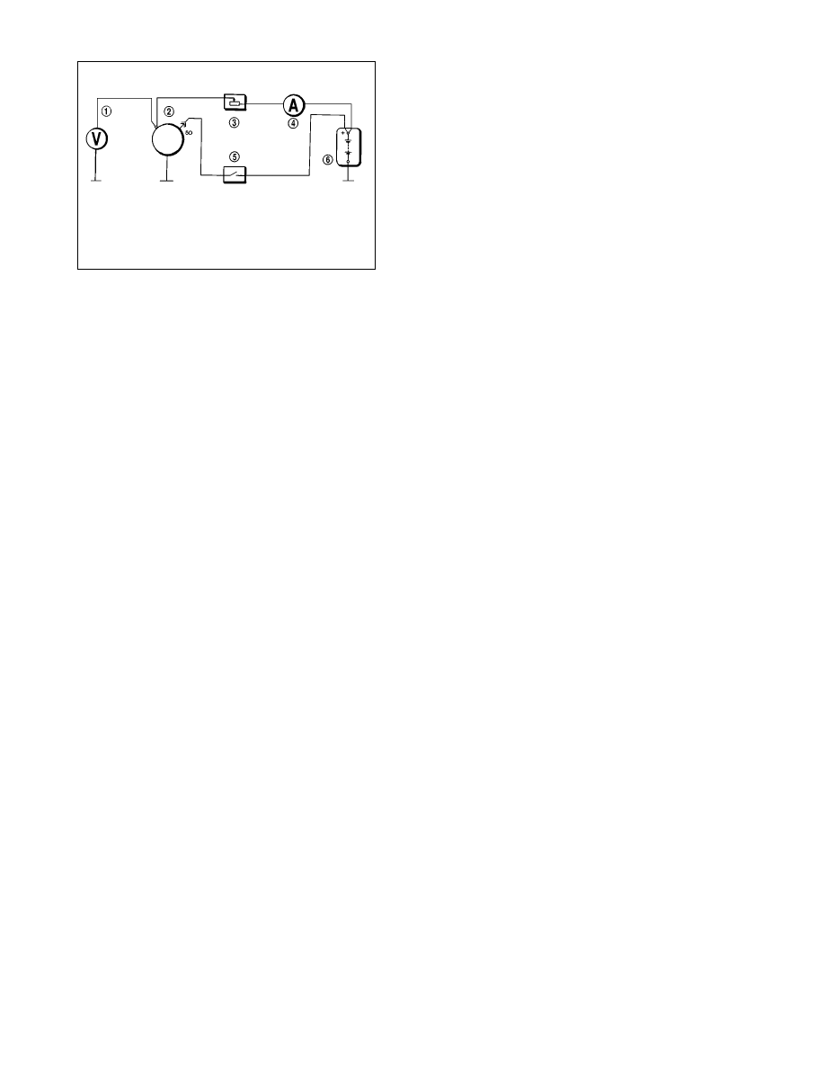
Starter motor - bench testing
If the starter motor fails to operate effectively, check it using
a tester. The wiring connections for the test are shown in Fig.7-
15. The cross-sectional area of leads to power source, ammeter
and starter solenoid terminal bolt should be at least 16 mm
2
.
The starter motor test temperature should be (25±5)°ë. The
brushes must slide smoothly on the commutator.
Functional test. By closing switch 5 (Fig.7-15), operate the
starter motor three times from a 12 volt source at different braking
conditions, eg. at the braking moments of 2; 6 and 10 N•m (0.2; 0.6
and 1 kgf•m). The starter motor should be switched on for no longer
than 5 seconds with minimum 5 second intervals in-between.
If the starter motor fails to turn the tester ring gear or pro-
duces unusual noise, dismantle the starter motor and examine its
components.
Fully locked ring test. Lock the tester ring gear, operate the
starter motor and measure the current, voltage and braking
moment to be maximum 550 amps, 7.5 volts and at least 13.7
N•m (1.4 kgf•m) respectfully. Do not switch on the starter motor
for over than 5 seconds.
When the braking moment is below, while the current is over
the values specified, the likely reason is an internal short-circuit of
the stator or armature winding or earthed winding.
When the braking moment and current are below the values
specified, the possible cause is an oxidized or dirty commutator,
severely worn brushes or weak springs, sticking brushes, loose
stator winding terminals, eroded or burnt solenoid terminal bolts.
At fully locked condition, the starter armature must not turn;
when otherwise the one-way clutch is faulty.
Dismantle the starter motor, replace or overhaul damaged
components to remedy the situation.
No-load test. Disengage the tester ring gear from the starter
motor pinion. Operate the starter motor, measure the current flow
and armature shaft speed to be respectively maximum 60 amps
and (5000±1000) rpm at 11.5-12 volts across the starter motor
terminals.
If the amperage and drive shaft rpm readings differ from the
values specified, the possible causes are likely to be the same as
those for the test described above.
Solenoid test. Insert a shim of 12.8 mm between stop collar
21 (Fig.7-13) and pinion and operate the solenoid. The solenoid
cut-in voltage, with the pinion resting against the shim, should not
exceed 9 volts at ambient (20±5)°ë. Any higher voltage indicates
the solenoid or drive failure.
Starter motor relay. The relay cut-in voltage should not
exceed 8 volts at (23±5)°ë. When higher, it is an indication of a
failed relay or drive.
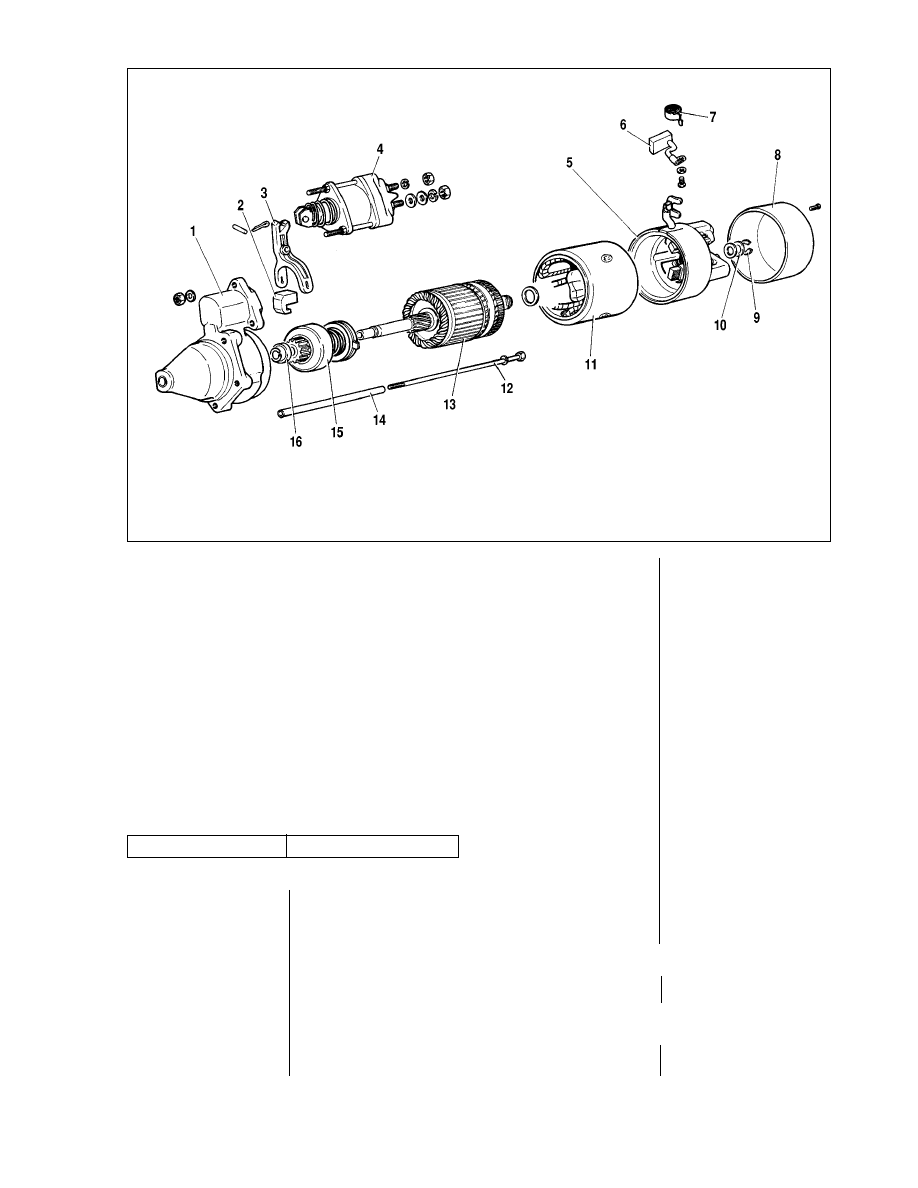
Starter overhaul
Dismantling
Undo the nut on the lower solenoid terminal bolt and discon-
nect the stator winding lead. Undo the solenoid retaining nuts and
remove the solenoid. Remove the end cap (Fig.7-16) from the
pinion-end cover.
Unscrew and remove protective case 8. Recover lock ring 9,
undo clamp bolts 12 and separate yoke 11 with housing 5 from
housing 1 with armature 13.
Unscrew the brush holders from the stator winding leads,
then separate the yoke from the commutator end housing. Extract
springs 7 and brushes 6.
Undo the cotter pin and withdraw the lever and armature /
actuator assembly, next disconnect the operating lever.
147
1. Bench test starter motor, renew
overrun clutch
2. Renew lever or refit pivot shaft
3. Renew clutch
1. Tighten retaining nuts or over-
haul starter motor
2. Check starter fitting
3. Renew starter motor
4. Tighten pole retaining screw
5. Renew drive or flywheel
6. Carry out the following:
- renew operating lever;
- clean and lubricate splines with
motor oil;
- renew clutch or solenoid;
- renew damaged components;
- renew solenoid or eliminate stick-
ing
- check correct contact closing at
different key positions; renew faulty
contact unit
1. Recharge battery
2. Check leads and connections
between battery and solenoid ter-
minal 50
3. Renew solenoid
148
Fig.7-13. Starter motor (35.3708 model):
1 - pinion; 2 - overrun clutch; 3 - guide ring; 4 - rubber plug; 5 - operating lever; 6 - drive-end housing; 7 - relay armature; 8 - relay winding; 9 - contact plate; 10 - relay
cover; 11 - terminal bolts; 12 - commutator; 13 - brush; 14 - armature shaft bush; 15 - commutator-end housing; 16 - end cover; 17 - housing; 18 - stator pole; 19 - arma-
ture; 20 - intermediate ring; 21 - stop collar
Fig.7-14. Starter wiring connections:
1 - starter motor; 2 - battery; 3 - alternator; 4 - starter cut-in relay; 5 - ignition switch
To withdraw the actuator unit from the armature, retrieve the
circlip from under stop collar 16. Dismantle the actuator unit after
removing the lockwasher from the clutch hub.
To dismantle the solenoid, undo the clamp bolt nuts and
unsolder the winding leads from terminal 50 and from the end
which is secured at the bottom solenoid terminal bolt.
Once the starter motor has been dismantled, blow its parts
with compressed air and wipe clean.
Components - inspection
Armature. Using a megohmmeter or a 220 v test lamp, check
the armature for the earthed winding. The voltage through the test
lamp is supplied to the commutator segments and armature core.
An illuminated lamp is an indication of a commutator being short-
ed to earth. When using the megohmmeter, the reading should be
at least 10 kOhms. Renew the earthed armature.
Using a specialized device, check for internal faults in the
armature winding and commutator segments, check for loose
connections where the winding wires are soldered to the com-
mutator.
Inspect the commutator. When dirty or burnt, sand it with fine
emery paper. Check the runout between the core and shaft jour-
nal. Renew the armature when the runout is over 0.08 mm.
Check the surfaces of splines and armature shaft journals.
There should be no scuffs, scores or wear. In the event the shaft
surface has yellow marks because of the pinion bush, remove
the marks with the help of fine emery paper, since this can pos-
sibly cause a pinion jam in the shaft.
Actuator unit. The starter motor actuator unit should operate
over the armature shaft smoothly, without jams. The pinion
should turn on the armature shaft in the direction of the armature
rotation at a maximum torque of 0.27 ç•Ï (2.8 kgf•cm).
The pinion is not supposed to turn in the reverse direction. If
the teeth are scored, regrind them with a small-diameter fine
abrasive disc.
When the drive-associated components are damaged or
badly worn, renew the actuator assembly.
Stator. Using megohmmeter or a 220 v test lamp, check the
stator winding is not earthed.
The test lamp voltage is supplied to the common winding ter-
minal and starter housing. When the bulb is lit up or megohm-
meter resistance reading is below 10 kOhm, or if the windings
have evidence of overheating (blackened insulation), renew the
housing complete with the windings.
Housings. Inspect the housings for cracks. If this is the case,
replace the housings with new ones.
Examine the bushes. When they are worn, renew the com-
plete housings or only the bushes. When the new bushes are
pressed-in, ream them to 12.015+0.03 mm.
Make sure the brush holders are properly secured on the
commutator end housing. The «positive» brush holders must not
be earthed. The brushes should slide smoothly in the holder
slots. Renew the brushes worn to 12 mm in height, but first run
them in to the commutator.
Using the dynamometer, check the spring load at the brush-
es to be 9.8±0.98 N (1±0.1 kgf) for new brushes, renew the
spring, when applicable.
Solenoid. Check the solenoid armature for smooth opera-
tion. Using ohmmeter, check the closing of the solenoid terminal
bolts via a contact plate. When there is no contact, the solenoid
should be dismantled and the terminal bolts to be sanded with
fine emery paper or a superfine flat file.
You may turn the terminal bolts 180°C in case they are badly
damaged at the contact point with the contact plate.
Reassembly
Assemble the starter motor in reversal of the dismantling pro-
cedure. Before reassembly lubricate the armature shaft splines
and freewheel hub, pinion and housing bushes with motor oil.
Lubricate drive guide ring with Litol-24 grease.
Protect the clamp bolt passing under the stator coils with an
insulating plastic tube.
Select shim 10 thickness (Fig.7-16) to ensure maximum
armature axial play of 0.5 mm. On reassembly, bench test the
starter motor.
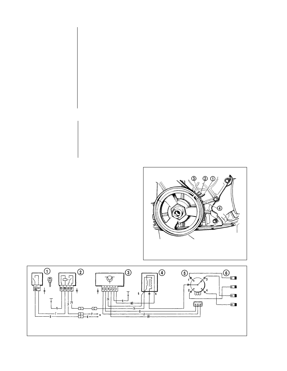
Ignition system
General description
The ignition system is breakerless. It comprises ignition dis-
tributor 5 (Fig.7-17), spark control module 3, ignition coils 4, spark
plugs 6, ignition switch 1 with relay 2 (113.3747-10 model) and
high-tension (HT) leads. The spark control module monitors the
supply circuit of the ignition coil primary winding. Control pulses to
the control module are generated by the Hall sensor housed in
ignition distributor 6.
149
Fig.7-15. Wiring connections for starter motor testing:
1 - voltmeter with scale limit at least 15 v; 2 - starter motor; 3 - rheostat, 800
amps; 4 - amperemeter shunted to 1000 amps; 5 - switch; 6 - battery
Ignition distributor is of 3810.3706 model, four-event
sparking rate, non-shielded, with vacuum and centrifugal
advance units, with built-in Hall sender.
Spark control module is of 3620.373 model, or 76.3734, or
RT1903, or PZE4022, or ä563.3747 model. The module process-
es the control output pulses from the Hall sender into current
pulses for the ignition coil primary winding.
Ignition coil is of 8352.12, or 27.3705, or 027.3705, or
27.3705-01 model, oil-filled, sealed, open-loop magnetic circuit.
Spark plugs are of Ä17ÑÇêå model, or Ä17ÑÇêå1 model
with suppressant chokes.
Ignition switch is of 2101-3704000-11 model, theft-deterrent.
Fault diagnosis
Engine will not start
1. Hall sender pulses fail to reach
control module:
- broken circuit between sender
and control module;
- Hall sensor faulty
2. No pulses to primary winding:
- broken circuit between control
module and solenoid or control
module and ignition coil;
- control module faulty;
- ignition switch or ignition relay
failed
3. No HT to spark plugs:
- HT lead ends loose, broken off or
oxidized; leads dirty or insulation
damaged;
- carbon brush worn or damaged,
or has no contact with rotor arm;
- tracking through cracks or burns
in distributor cap or rotor, through
damp or foul distributor cap inside;
- distributor rotor resistor blown;
- ignition coil damaged
4. Oily spark plugs or wrong elec-
trode gap
5. Spark plug damaged (perished
insulation)
6. Wrong HT leads connection to
distributor cap terminals
7. Wrong ignition timing
Engine operates erratically or stalls at idle
1. Ignition timing too advanced
2. Electrode gap excessive
Engine running unstable or irregular at high crankshaft speeds
Weak weight springs in ignition
distributor
150
1. Carry out the following:
- check wiring and connections,
renew damaged wires;
- check Hall sensor using adapter
and voltmeter; renew failed sensor
2. Carry out the following:
- check wires and connections;
renew damaged wires;
Renew springs, run functional
bench test of centrifugal unit
Cause
Remedy
- check control module with oscillo-
scope; renew faulty control module
- check, renew faulty contact unit of
ignition switch or ignition relay
3. Carry out the following:
- check and restore connections,
clean or renew leads;
- check and when necessary renew
carbon brush;
- check, clean cap from moisture
and carbon deposits, renew cap
and rotor in case of cracks;
- renew resistor;
- renew ignition coil
4. Clean and regap spark plugs
5. Renew spark plugs
6. Reconnect leads as per firing
order 1-3-4-2
7. Check and adjust ignition timing
1. Check, adjust ignition timing
2. Check, adjust electrode gap
Fig.7-16. Exploded view of starter motor:
1 - drive end housing with intermediate ring; 2 - rubber plug; 3 - operating lever; 4 - solenoid; 5 - commutator end housing; 6 - brush; 7 - brush spring; 8 - protective case;
9 - stop ring; 10 - adjusting shim; 11 - yoke; 12 - clamp bolt; 13 - armature; 14 - insulating pipe; 15 - overrun clutch with pinion; 16 - stop collar
Engine gasps at all speeds
1. Ignition wires damaged, con-
nections loose or lead ends oxi-
dized
2. Electrodes worn or oily spark
plugs, strong fouling; cracks in
plug insulation
3. Carbon brush in ignition distrib-
utor worn or damaged
4. Strong burning of central con-
tact point on distributor rotor arm
5. Cracks, fouling or burnings of
rotor arm or distributor cap
6. Control module faulty - wrong
waveform of ignition coil primary
winding impulses
Engine lacking power or sluggish
1. Incorrect ignition timing
2. Jammed distributor weights,
weak weight springs in ignition dis-
tributor
3. Spark control module faulty -
wrong waveform of ignition coil pri-
mary winding pulses
WARNING. The vehicle is fitted with high energy transis-
torized ignition system with extended application of elec-
tronic components. Caution should be exercised to avoid
personal injury or damage to electronics. Always observe
the following rules.
Do not touch any ignition system parts (spark control
module, coil or HT leads) when the engine is running.
Do not start the engine through a spark plug gap and do
not check the ignition system through sparking between the
ends of the spark plug leads and earth lead.
Do not route LT and HT ignition leads together within one
wiring harness.
Always ensure the spark control unit is reliably earthed
through the retaining dowels, or its trouble-free operation
will be affected.
With ignition switched on, never disconnect the leads
from the battery posts and never remove the connector from
the spark control unit, since it may result in higher voltage to
some components and damaged control module.
Ignition timing - adjustment
Refer to Attachment 3 for the advance angle BTDC at crank-
shaft speeds of 750-800 rpm.
To check the ignition timing there provided three marks - 1, 2
and 3 (Fig.7-18) on the timing cover and mark 4 in the crankshaft
pulley, which corresponds to TDC of pistons No1 and No4 when
aligned with mark 1 on the timing cover.
The ignition timing is best checked and adjusted by means of
a stroboscopic timing light. Follow the procedure below:
- connect the timing light positive clamp to the battery positive
post, earth terminal clamp to the battery negative post, connect
the timing light terminal to No1 cylinder HT lead. Highlight in chalk
timing mark 4 on the crankshaft pulley;
151
1. Examine leads and connections.
Renew damaged leads
2. Examine plugs, regap spark
plugs, renew damaged spark plugs
3. Renew carbon brush
4. Clean central contact
5. Inspect, renew rotor or cap
6. Check spark control module with
oscilloscope, renew faulty control
module
1. Check and adjust ignition timing
2. Examine and renew damaged
parts
3. Check spark control module with
oscilloscope, renew faulty control
module
Fig.7 -17. Wiring diagram of ignition system:
1 - ignition switch; 2 - ignition solenoid; 3 - spark control unit; 4 - ignition coil; 5 - ignition distributor; 6 - spark plugs
Fig.7-18. Ignition timing marks:
1 - TDC mark; 2 - 5°advance timing mark; 3 - 10° advance timing mark; 4 - TDC
mark on crankshaft pulley
- start the engine and point the flashing timing light at the tim-
ing mark on the pulley; when the ignition is correct, then at idling
speed the TDC mark on the flywheel should be as outlined in
Attachment 3.
To adjust the ignition timing, switch off the engine, slacken
the nuts securing the ignition distributor and turn the latter to the
angle desired (clockwise for advance and anticlockwise for retard
when viewed from the distributor cap end). Tighten the nuts and
recheck the ignition timing.
For easier ignition timing adjustment there provided the
respective graduations and (+)/(-) marks on the distributor flange.
A graduation on the distributor flange corresponds to eight
degrees (8°) of the crankshaft turn.
Another effective way for checking the ignition timing is to
use an oscilloscope analyzer, when this tool is available.
Refit the distributor as following:
- turn the crankshaft to the position of compression beginning
at No1 piston; then still turning the crankshaft, align mark 4 with
mark 1;
- remove the distributor cap, turn the rotor arm so that its
exterior contact faces the No1 piston contact on the distributor
cap;
- holding the distributor driveshaft stationary, insert it to the
cylinder block so that the axial line through the spring clamps is
nearly parallel to the engine axial line;
- locate the distributor to the cylinder block, refit the distribu-
tor cap, reconnect the wiring, check and adjust timing ignition.
Ignition components - bench testing
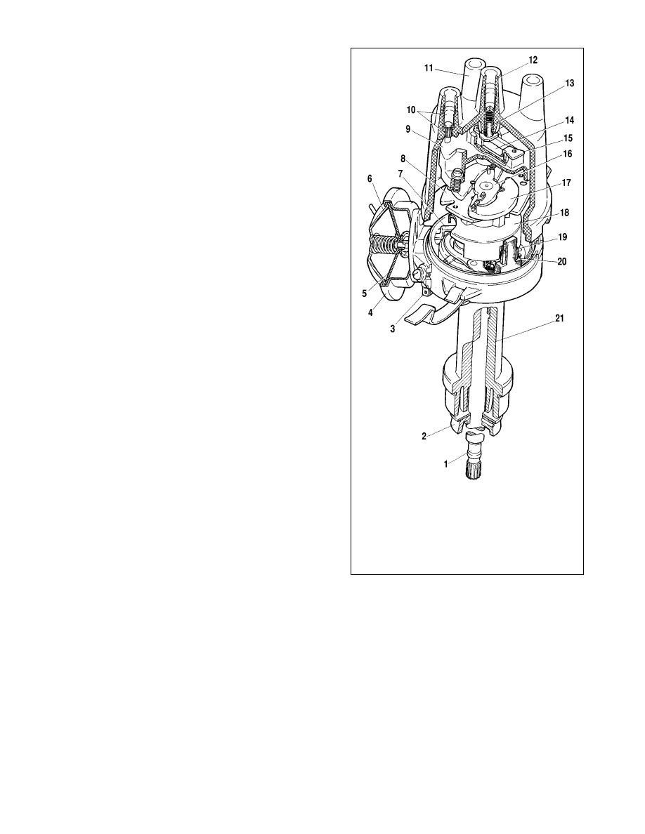
Ignition distributor
The distributor of 3810.3706 model is shown in Fig.7-19.
Functional test. Mount the distributor on the tester intended
for checking electrical devices. Connect it to a variable speed
motor.
Connect the distributor terminals to the ignition coil, spark con-
trol module and battery of the tester similar to the wiring in the vehi-
cle. Connect four terminals of the distributor cap to the spark box
with adjustable gaps.
Set the spark gap to 5 mm, switch on the tester motor and
operate the distributor driveshaft clockwise for some minutes at
2000 rpm. Increase the gap to 10 mm and check for internal dis-
charges in the distributor. These can be recognized by specific
sounds or weak or intermittent sparking in the tester spark box.
No noise should be produced by the ignition distributor at any
driveshaft speed.
Automatic ignition advance control. Mount the ignition dis-
tributor on the tester and connect it to terminals 3, 5 and 6 of
tester control module 1 (Fig.7-20). Connect control module ter-
minal 4 to the tester «plus», while terminal 1 - to the tester
«breaker» terminal. Set the spark gap to 7 mm.
Switch on the tester motor and operate the distributor shaft at
500-600 rpm. On the tester graduated disc note the angle at
which one of the four sparkings occurs.
While increasing the speed in steps of 200-300 rpm and
watching the disc, determine the advance angle with respect to
the distributor shaft speed. Compare the resulting centrifugal
advance pattern to that in Fig. 7-21.
When the pattern differs from that shown in Fig.7-21, it can
be adjusted by bending the weight spring brackets of the cen-
trifugal advance unit. Bend the thinner spring bracket for speeds
152
Fig.7-19. Ignition distributor (3810.3706 model):
1 - shaft; 2 - oil screen collar; 3 - connector; 4 - vacuum advance housing; 5 -
diaphragm; 6 - vacuum advance cover; 7 - vacuum advance operating rod; 8 -
bearing plate, centrifugal advance unit; 9 - ignition distributor rotor; 10 - side
electrode and terminal; 11 - cover; 12 - centre electrode and terminal;
13 - centre electrode carbon brush; 14 - resistor; 15 - outside rotor contact
breaker point; 16 - centrifugal advance unit plate; 17 - weight; 18 - screen; 19 -
Hall sensor bearing plate; 20 - Hall sensor; 21 - ignition distributor body
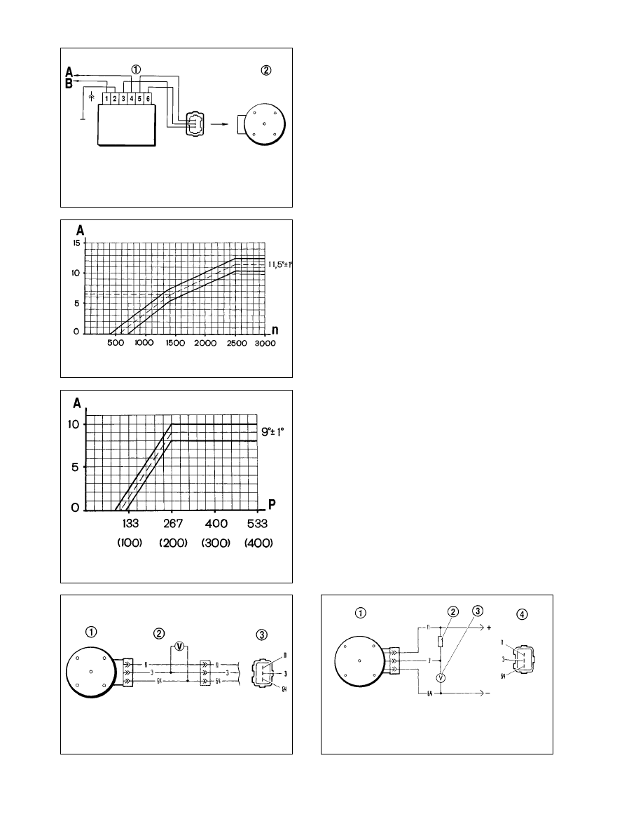
up to 1500 rpm or the thicker spring bracket for speeds over 1500
rpm. Increase the spring tension for a smaller angle (retard) or
decrease the spring tension for a bigger angle (advance).
To obtain the vacuum advance pattern, connect the vacuum
advance unit to the vacuum pump of the tester.
Operate the tester motor and run the distributor driveshaft at
1000 rpm. Watching the tester graduated disc, note the angle at
which one of the four sparking events occurs.
Smoothly increase the vacuum through every 26.7 gPa (20
mm Hg) and make note of the advance angle with respect to the
initial value. Compare the resulting advance pattern with that in
Fig.7-22.
Note the Hall sensor mounting plate invariably returns to its
original position after vacuum has been removed.
Hall sensor. The Hall sensor produces the output voltage if
there is a steel vane in the air gap. The output is around zero
volts when there is no vane in the gap.
With the distributor removed from the engine, the sensor can
be tested as illustrated in Fig.7-24 at supply voltage of 8-14 volts.
While slowly rotating the distributor shaft, measure the output
using a voltmeter. The voltage should change sharply between
the low level (0.4 volt maximum) and the high level, which must
be maximum 3 volts below the supply voltage.
The Hall sensor can be tested in the vehicle as shown in
Fig.7-23. Adapter 2 and a voltmeter are connected across the
distributor connector and wiring harness connector. Switch on
the ignition and measure the sensor output with a voltmeter,
while slowly rotating the crankshaft with a special tool. The out-
put voltage readings should meet the specification.
Ignition coil
Check resistance of the winding and insulation.
For the ignition coil of 27.3705 model the resistance at 25°ë
should be 0.45±0.05 Ohm for the primary winding and 5±0.5
kOhm for the secondary winding. For the ignition coil of 8352.12
model the resistance of the primary winding is 0.42±0.05 Ohm,
while that of the secondary winding is 5±1 kOhm.
153
Fig.7-24. Wiring diagram for Hall sensor test on the removed ignition
distributor:
1 - ignition distributor; 2 - 2kOhm resistor; 3 - voltmeter of minimum 15 v scale
and minimum 100 kOhm internal resistance; 4 - view on the ignition distributor
connector
Fig.7-23. Wiring diagram for Hall sensor in-vehicle test:
1 - ignition distributor; 2 - adapter with voltmeter of at least 15 v scale and inter-
nal resistance of minimum 100 kOhm; 3 - view on ignition distributor connector
Fig.7-20. Checking the ignition distributor on the test bench:
1 - spark control module; 2 - ignition distributor; Ä - to test bench «plus» terminal;
Ç - to test bench «breaker» terminal
Fig.7-21. Centrifugal advance ignition distributor map:
Ä - advance timing, degrees; n - ignition distributor shaft speed, rpm
Fig.7-22. Ignition distributor vacuum advance map :
Ä - advance, degrees; ê - vacuum gPa (mm Hg)
Resistance of the insulation to earth should be at least 50
MOhm.
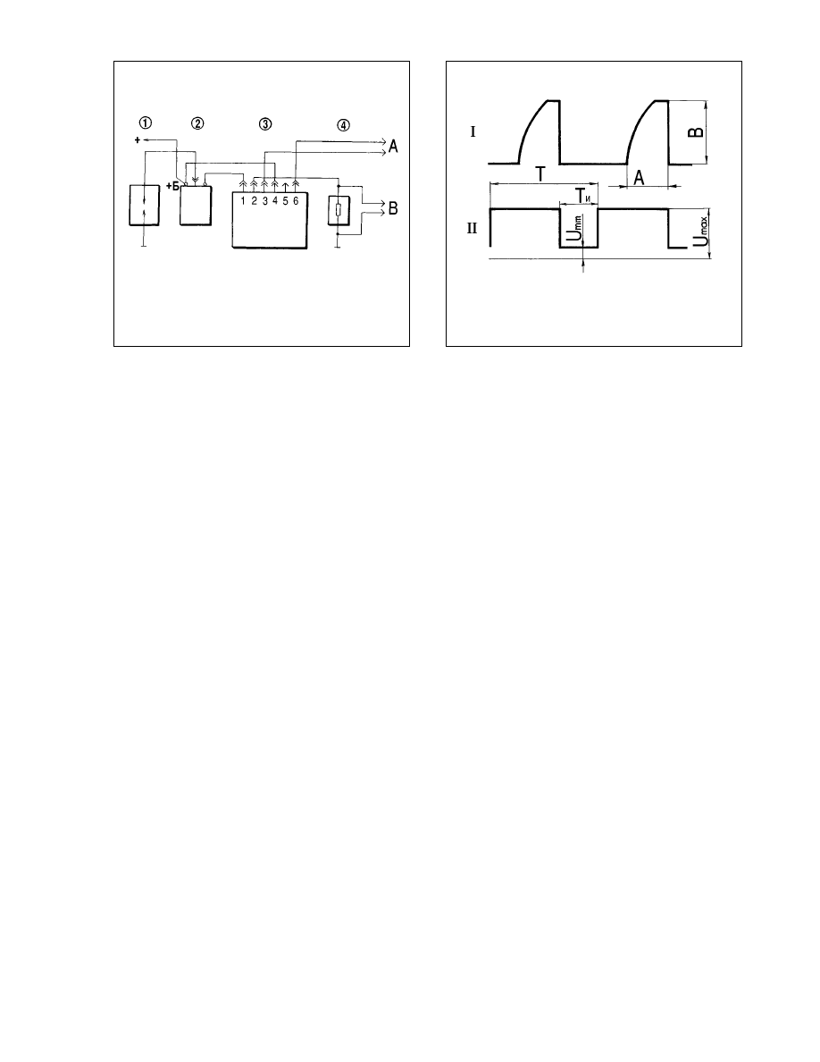
Spark control module
The spark control module can be tested using an oscilloscope
and square wave pulse generator connected as shown in Fig.7-
25. The pulse generator resistance should be 100-500 Ohm. It is
preferable to use a double-channel oscilloscope - the 1st channel
is for the generator pulses, while the 2nd channel - for the control
module pulses.
Square wave pulses, simulating those of the distributor sen-
sor, are supplied to the module terminals 3 and 6. The pulse fre-
quency should be within 3.33 - 233 Hz, while the duty cycle (peri-
od-to-pulse length ratio, í/íË) should be set to 3. The maximum
voltage (Umax) is 10 volts, the minimum voltage (Umin) should
not exceed 0.4 volts (Fig.7-26, II). A sound control module should
generate the pulses as shown in oscillogram I.
For 3620.3734 and 76.3734 modules at the supply voltage
13.5±0.5 volts, the current flow (Ç) should be from 7.5 to 8.5
amps. There is no standard dwell (current saturation) (Ä).
For RT1903 module at the supply voltage of 13.5±0.2 volts
and frequency of 25 Hz, the current flow is 7 to 8 amps, while the
dwell is 5.5 to 11.5 milliseconds.
For PZE4022 module at the supply voltage of (14±0.3) volts
and frequency 25 Hz, the current flow is 7.3-7.7 amps, while the
dwell is not specified.
For ä563.3747 module at the supply voltage of (13.5±0.5)
volts and frequency 33.3 Hz, the current flow is 7.3-7.7 amps,
while the dwell is not specified.
Any distortions in the pulse waveform can result in misfires or
retarded ignition. The engine will tend to overheating and will not
develop maximum power.
Spark plugs
If the spark plugs are foul or have deposits, then prior to test-
ing clean them by means of a sand blasting machine and blow
with compressed air. When the insulator nose is covered with
light tan to greyish brown deposits, there is no need to clean
them, as it is indicative that the mixture is correct and the engine
is in good condition.
Once the plugs have been cleaned, examine them and set
the correct spark gap. If the insulator is chipped, cracked or the
side electrode weld is perished, renew the spark plug.
Check the spark plug gap (it is to be 0.7-0.8 mm) with a round
wire feeler blade. It is not recommended to use a flat feeler blade
since it is cannot account for erosion (cut-out) on the outer electrode
which appears in course of operation. Bend, open or close, the
outer (side) plug electrode only until the correct gap is achieved.
Leak test. Screw the plug into the seat on the tester and
tighten it to a torque of 31.4-39.2 N•m (3.2-4 kgf•m). Build up the
pressure of 2 åPa (20 kgf/cm
2
) in the tester chamber.
Take an oil cup and place a few drops of oil or kerosine on
the spark plug; the broken tightness is evident through the air
bubbles between the insulator nose and metal plug body.
Electrical test. Insert the spark plug to the seat on the tester
and tighten to the torque specified above. Adjust the gap between
the spark box electrodes to 12 mm, which corresponds to 18
kvolts; afterwards, using a pump, build the pressure up to 0.6
åPa (6 kgf/cm
2
).
Fit the end of the HT cable to the plug and apply HT pulses.
The spark plug is sound when a good spark is observed
through the tester sight window. When sparking takes place
between the spark box electrodes, decrease the pressure in the
tester. Next recheck the pressure value when the spark jumps
between the spark plug electrodes.
154
Fig.7-26. Displaying pulse waveform at the oscilloscope:
I - control module pulses; II - alternator pulses; Ä - dwell (current saturation
time); Ç - maximum current; í - pulse period; íË - pulse width
Fig.7-25. Checking the spark control module:
1 - spark gap; 2 - ignition coil; 3 - control module; 4 - 0.01 Ohm resistor (1%, at
least 20 W); Ä - to square wave generator; Ç - to oscilloscope
When sparking occurs at the pressure below 0.3 åPa (3
kgf/Òm
2
), the spark plug is defective.
Only a few sparks are allowed in the spark gap; when no
sparking is observed either on the spark plug or in the spark gap,
it is likely that the insulation is cracked and the central electrode
arcs internally to earth. Always discard such spark plugs.
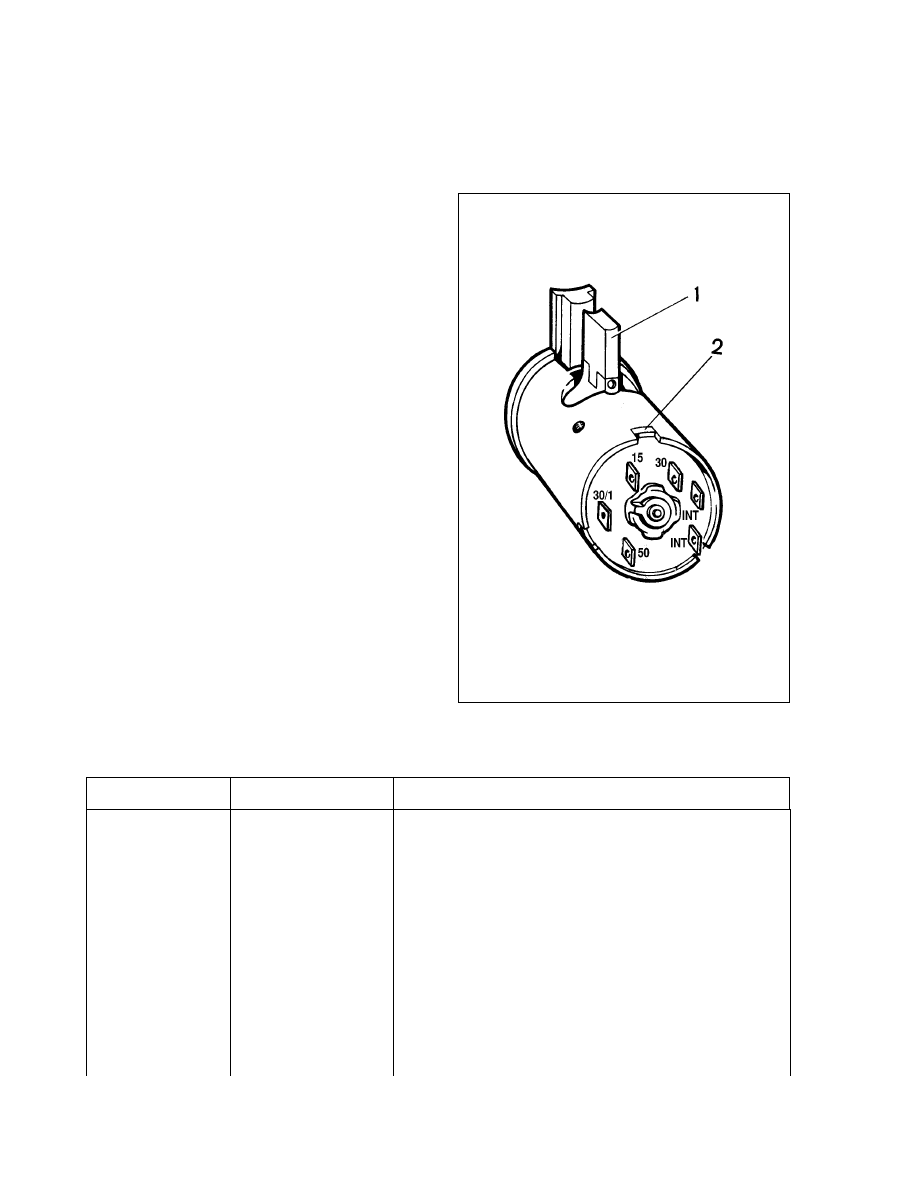
Ignition switch
Check the ignition switch contacts are closing properly at dif-
ferent key positions (Table 7-5) and theft-deterrent device is func-
tional. The battery and alternator voltage is supplied to terminals
30 and 30/1. The vacant terminal «INT» is intended for radio/cas-
sette player connection.
The steering lock pin moves out when the key is turned to
position III «parking» and is then removed from the switch. The
lock pin moves in after the ignition key is turned from position III
«parking» to position 0 «ignition off». The key can only be
removed from position III.
When inserting the contact part into the ignition switch hous-
ing, locate it so that terminals 15 and 30 are on the lock pin side
(Fig.7-27), ensure the wider end of the contact part is well within
the wider slot of the ignition switch housing.
Suppression components - testing
The following is used for interference suppression:
- 1 kOhm resistor in the distributor rotor arm;
- resistive HT cables of (2000±200) Ohm/m for red leads
(èÇÇè-8) or (2550±270) Ohm/m for blue leads (èÇèèÇ-40);
- 4-10 kOhm resistors in the spark plugs;
- 2.2 microfarad capacitor in the alternator.
The leads and resistors are checked with an ohmmeter. Refer
to subsection «Alternator» for the capacitor checking procedure.
Lighting and signalling
155
Fig.7-27. Ignition switch contact unit:
1 - lock pin; 2 - wider part of contact unit
Table 7-5
Circuits activated at different ignition switch positions
Position
Live contacts
Circuits activated
0 (Off)
30 and 30/1
–
I (Ignition)
30-INT
–
30/1-15
Alternator field winding. Ignition system. Direction indicators. Instruments.
Heater unit. Heated rear window. Wipers: windscreen, rear window, headlight .
II (Starter motor)
30-INT
–
30/1-15
Refer to position I
30-50
Starter motor
III (Parking)
30-INT
156
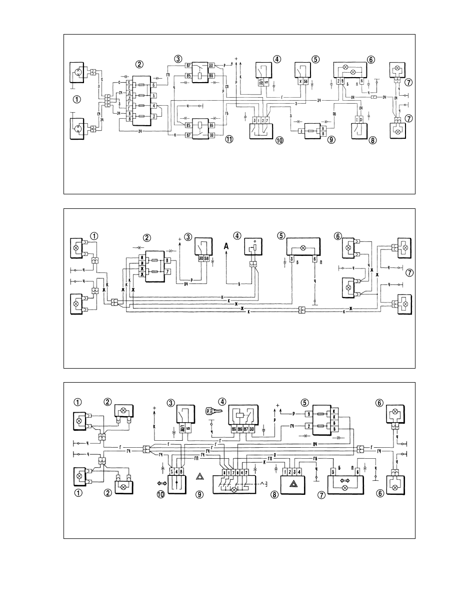
Fig.7-29. Wiring diagram for exterior lighting:
1 - sidelights in headlights; 2 - fusebox; 3 - exterior light switch; 4 - instrument illumination switch; 5 - exterior light warning lamp in instrument cluster; 6 - number plate
lamp; 7 - sidelights in rear light units; Ä - to illumination lamps for instruments, switches and heater controls
Fig.7-28. Wiring diagram for headlight and foglight:
1 - headlights; 2 - main fusebox; 3 - low beam relay; 4 - ignition switch; 5 - exterior light switch; 6 - warning lights: high beam (left) and fog lamp (right); 7 - rear fog light;
8 - fog light switch; 9 - complementary fusebox; 10 - headlight switch; 11 - high beam relay
Fig.7-30. Wiring diagram for direction indicators and hazard flashers :
1 - direction indicators in headlights; 2 - side repeat indicators; 3 - ignition switch; 4 - ignition relay; 5 - fusebox; 6 - direction indicators in rear light cluster; 7 - direction indi-
cators warning light in instrument cluster; 8 - indicators flasher relay; 9 - hazard warning flasher switch; 10 - direction indicators switch
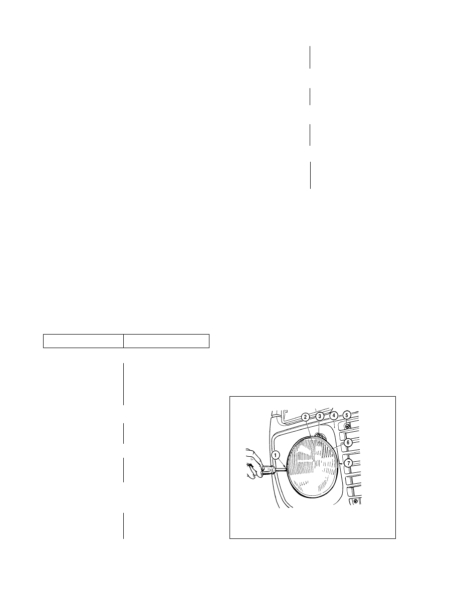
General description
The headlight wiring diagram is shown in Fig.7-28.
High and low beam is operated through supplementary relays
3 and 11.
The control voltage to the relay winding is supplied from
headlight combination switch 10 when external light push switch
5 is fully depressed.
Regardless the position of push switch 5, the high beam can
be briefly switched on by pulling combination switch 10 for light
signalling. By doing this, stalk switch 10 terminal is energized
directly from the power source bypassing the ignition switch.
Some vehicles are fitted with the hydraulic headlight adjuster
to align the headlight beam depending on the vehicle load.
The external light wiring diagram is shown in Fig.7-29.
The sidelights in the front and rear lights are operated by
means of exterior light switch 3.
Number plate lamp 6, instruments and switch illumination
lamps, sidelight warning lamp 5 are powered at the same time.
The wiring diagram for direction indicators/hazard warning
flashers is shown in Fig.7-30.
The left-hand and right-hand direction indicators are operat-
ed with the help of steering column combination switch 10.
When operated, hazard flashing switch 9 activates all direc-
tion indicators.
Flashing is enabled by relay 8.Fault diagnosis
Cause
Remedy
Lights do not come on
1. Fuses blown
2. Bulb filament blown
3. Switch or relay pins corroded
4. Damaged leads, corroded ends
of leads, loose lead connections
Brake light inoperative
Brake light switch inoperative
Failure to switch between low
and high beam
1. Corroded pins of combination
switch
2. High beam or low beam relay
faulty
Steering column levers ‡re
inoperative
1. Lever catch ball dropped
2. Lever catch recesses damaged
Turn signal self-canceling device inoperative
1. Cancelling mechanism seized
2. Combination switch guide ring
shoulders worn or broken
Steering column levers fail to switch between the positions
1. Lever catch balls jammed
2. Self-cancelling device seized
Turn signal warning light inoperative
1. Bulb filament blown
2. Indicators flasher relay faulty
Direction indicator warning light flashes at higher rate
1. Direction indicator bulb blown,
front or rear
2. Indicators flasher relay faulty
Headlight - adjustment
The headlight beams should be adjusted so that the area in
front of the vehicle is properly illuminated and the drivers of the
oncoming traffic are not dazzled with the dipped beam.
The headlights are adjusted by means of screws 1 and 7
(Fig.7-31) which allow to alter vertical and horizontal settings of
the reflector unit.
Headlight beam alignment is best carried out using optical
beam setting equipment. If it is not available, the adjustment can
be done using a screen.
A fully laden and equipped vehicle with a load of 735 N (75
kgf) to represent a driver should be positioned on level ground
facing a flat wall or screen (plywood board of approx. 2ı1 m or
similar) at a distance of 5 meters with the vehicle centre line being
normal to the screen. Before marking-off the screen, make sure
that the tyre pressures are correct; next swing the vehicle to set-
tle the springs and shock absorbers.
157
1. Renew fuses
2. Renew bulbs
3. Clean contacts
4. Check, renew damaged leads,
clean wire ends
Check with a test lamp, renew
faulty switch
1. Renew 3- stalk switch
2. Check and renew relay
1. Renew 3-stalk switch
2. Detto
1. Renew 3-stalk switch
2. Detto
1. Renew bulb
2. Renew indicators flasher relay
1. Renew bulb
2. Renew relay
1. Renew 3-stalk switch
2. Detto
Fig.7-31. Headlight alignment:
1,7 - headlight beam adjustment screws; 2 - optical unit; 3 - retaining screw,
optical unit rim; 4 - body front trim; 5 - trim retaining screw; 6 - optical unit rim
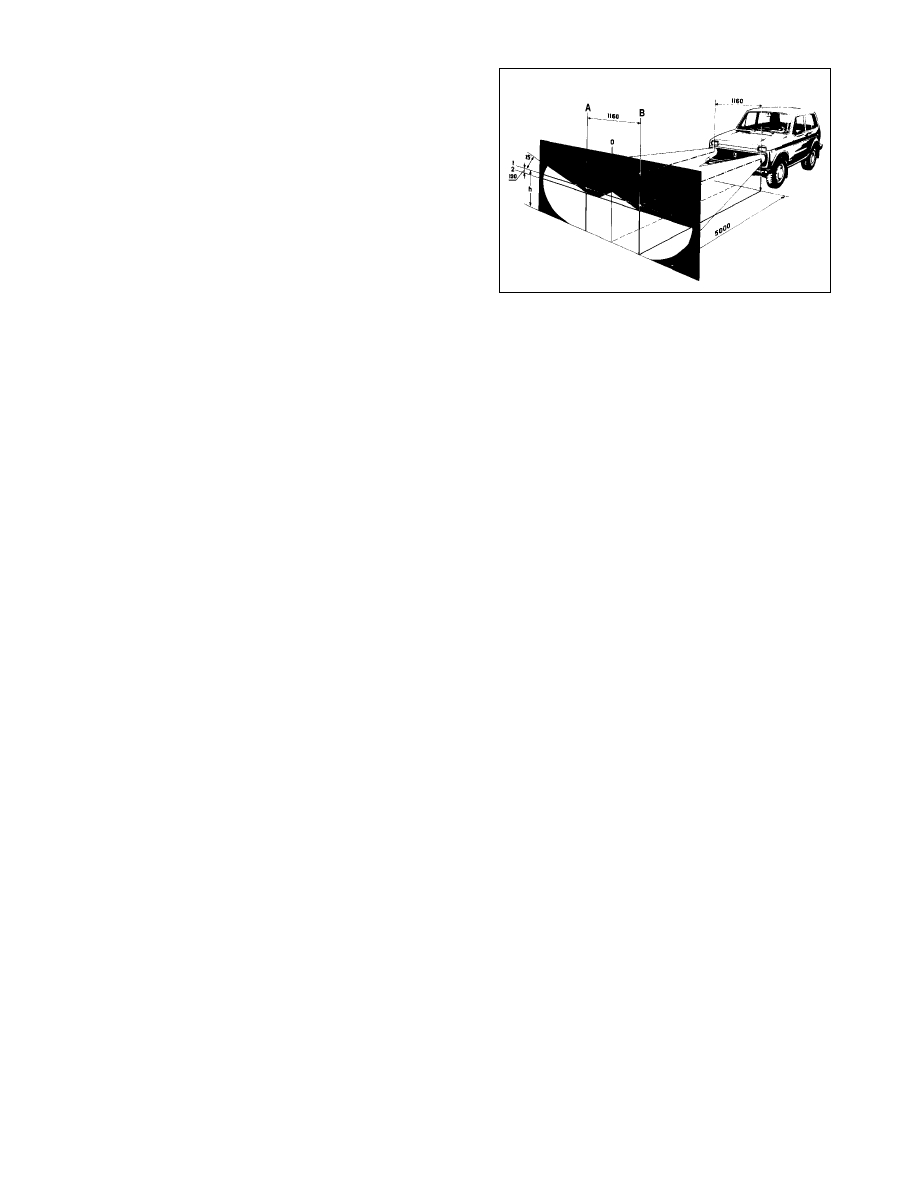
Three vertical lines should be drawn on the screen (Fig.7-32):
centre line O and lines A and B through the reference points Ö cor-
responding to each headlamp center. These lines should run sym-
metrical to the centre line of the car. Draw line 1 at the height of 600
mm which is the distance to the centres from the ground and 75
mm below draw line 2 passing through the centres of the headlight
beam patterns.
Make sure the facia-mounted switch of the headlamp aim
adjustment system is in the position corresponding to the load of
the driver only.
Switch on the lower beam. Using adjustment screws 1 and 7
(Fig.7-31), align the beams, first on the right-hand headlamp
(while the other is covered with a piece of cardboard or dark
cloth) and then on the left-hand headlamp (with the right-hand
one screened).
To adjust the headlight beam in the vertical plane, turn
screws 1 and 7 simultaneously in the same direction and to the
same number of turns. The difference in turns between the
screws (with the other screw intact) should not exceed 3 turns.
Horizontally the headlights are adjusted by means of screws
1 and 7, turned in opposite directions. If one screw is turned one
turn clockwise, the other should be turned one turn anticlockwise.
Some vehicles can be fitted with the headlights without the
hydraulic beam adjuster and have an alternatively mounted
adjuster screws, when the horizontal adjuster screw is on the left,
while that for vertical adjustment is fitted at the top.
If the headlights are correctly aligned, a cut-off at the top of
the beam patterns must be at line 2 (Fig.7-32), while the inter-
section points of horizontal and angled lines should coincide with
reference points Ö.
Bulb replacement
Headlight units. To replace a bulb:
- undo securing screws 5 and remove trim 4 (Fig.7-31);
- slacken screws 3 securing the headlight optical unit rim, turn
the rim anti-clockwise to remove it;
- withdraw the headlight optical unit and renew a failed bulb;
- refit the optical unit so that the retaining lugs enter the
recesses of the headlight inner rim.
Front lights. Undo two screws and remove the lens, then
slightly depress the bulb and turn it anticlockwise to remove.
Direction indicator side repeater. To renew a failed bulb,
first remove the holder complete with the bulb, working from the
engine bay.
Interior lamp. To renew a blown bulb, gently pull the lens up.
The lamp is held in the recess in the door centre pillar by two
spring clips.
Rear light unit. To replace a failed bulb in the rear light unit,
remove a plastic cap from the inside of the luggage compartment,
disconnect the terminal connector, squeeze the retaining lugs
and withdraw the base complete with the bulbs. Next depress the
bulb, turn it anticlockwise and withdraw.
Number plate light. Undo the retaining screws, remove the
light unit, detach the reflector lens and renew a blown bulb.
Hydraulic headlight adjuster
The hydraulic headlight adjuster system consists of the mas-
ter cylinder, fitted to the instrument panel, working cylinders on
the headlamps and connecting pipes. The cylinders and pipes
are filled with non-freezing hydraulic fluid. The hydraulic adjuster
is not serviceable and has to be renewed as a complete unit,
together with the cylinders and pipes, in the event of a failure.
When the beam setting is disturbed and alignment by means
of the adjustment screws on the headlight has failed, check the
cylinders and pipes for leaks. Remove the working cylinders and
check the rod travel to be (7±0.5) mm.
To replace a faulty headlamp adjuster, detach the pipe clips
from the wiring clamps, remove the control knob from the master
cylinder and undo the mounting nut. Detach the working cylinders
from the headlight units and push them together with seals into
the passenger compartment. Refit a new headlamp adjuster
using the reversal of the removal procedure.
Steering column combination switch
The steering column switch is secured to the steering column
support bracket with the help of the retaining strap.
Observe the following procedure when removing the steering
column combination switch:
- remove the steering wheel;
- remove both steering column shrouds;
- remove the instrument cluster and disconnect the steering
column switch wiring;
- release the retaining strap and withdraw the steering column
switch.
158
Fig.7-32. Headlight alignment
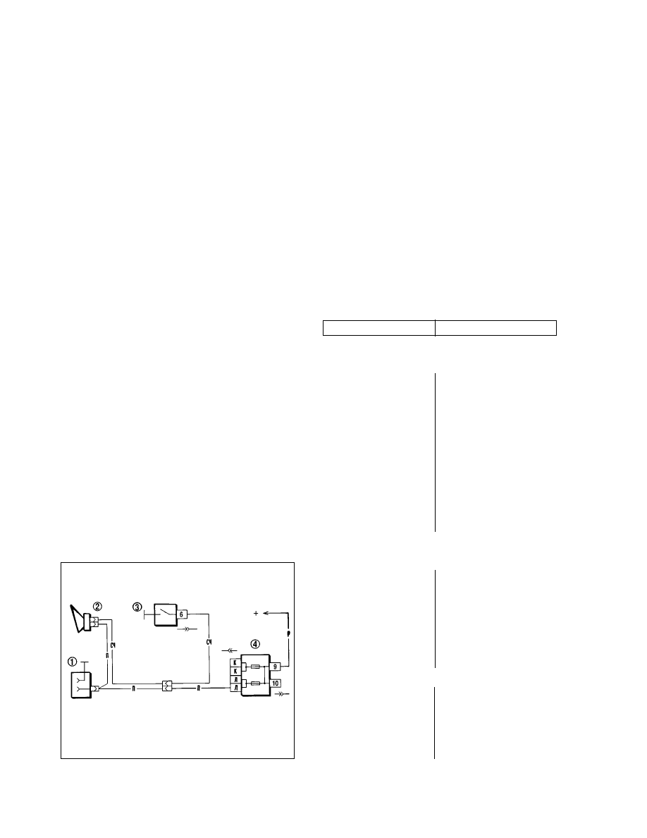
Indicators flasher relay
Relay 8 (Fig.7-30) (231.3747 model) is intended for intermit-
tent light signals both for direction indication and hazard flashing.
It also allows to identify a failed bulb in the direction indicator.
With good bulbs in the direction indication mode, the relay
ensures flashing warning light 7. With a failed bulb in the direction
indicators (blown bulb or broken bulb circuit), the direction indi-
cator and relevant facia warning light start flashing faster.
The relay is secured under the facia by the bolt welded to the
air intake wall. A faulty relay is not repairable and must be always
replaced with a new relay.
The relay should ensure the direction indicators flashing at a
rate of 90±30 cycles per minutes at 92 watt, ambient temperature
of - 20 to +50°ë and supply voltage between 10.8 and 15 volts.
Headlamp-on relay
The headlights are switched by means of relay 3 and 11
(Fig.7-28), model 113.3747-10, fitted below the instrument panel
on the left. Similar relays are used to switch the rear window heat-
ing, headlight wipe/wash.
The relay cut-in voltage at (23±5)°ë must not exceed 8 volts,
the winding resistance should be (85±8.5) Ohms.
Horn
The vehicle is fitted with a horn of model 20.3721. The horn
is located in the engine compartment behind the radiator grill.
The horn wiring diagram is shown in Fig.7-33.
When the volume is low or the horn emits harsh sound, adjust
it using the adjustment screw on the horn body unit until a satis-
factory sound is achieved.
In the event of the horn failure, inspect all connections and
condition of the switch contacts.
Windscreen wiper/washer
General description
The windscreen wipe/wash comprises motor, linkage and
blades. The windscreen wipe/wash wiring diagram is shown in
Fig.7-34.
There are two operating modes of the windscreen wiper: con-
tinuous operation and intermittent operation, ensured by a relay
of êë-514 model.
A thermal bimetal fuse is provided to protect against the
motor overheating in the event of the blades binding to the glass
or resistance to sweep.
The washer pump is combined with the motor and is fitted to
the washer fluid container in the engine compartment. The pump
motor is operated by pulling up the right-hand lever of the steer-
ing column combination switch.
Fault diagnosis
Cause
Remedy
Inoperative wiper motor and bimetal fuse, non-blown fuse 2 in
fuse and relay box
1. Motor supply wires damaged,
ends of wires in connectors cor-
roded
2. Wiper switch faulty
3. Motor brushes sticking, foul or
burnt commutator
4. Broken wires between motor
brushes and connector
5. Bimetal thermal fuse damaged
6. Motor armature winding lead
broken
Wiper motor inoperative, bimetal thermal fuse operative or fuse 2
in fuse box blown
1. Wiper arms bent or conflict with
bodywork
2. Wiper blades stuck because of
ice or snow
3. Foreign object in wiper mecha-
nism
4. Short-circuit in motor armature
winding
Wiper motor fails to operate intermittently
1. Wiper switch faulty
2. Wiper relay damaged:
- break in relay winding;
- shorted wires in contact part;
- clearance between relay breaker
contacts
159
Fig.7-33. Horn wiring diagram:
1 - inspection lamp socket; 2 - horn; 3 - horn switch; 4 - fusebox
1. Inspect and renew leads when
found damaged. Clean wire ends
2. Renew 3-stalk switch
3. Inspect, eliminate wiper blades
sticking or renew damaged compo-
nents, clean commutator
4. Check and when necessary sol-
der wires
5. Clean thermo-bimetal fuse con-
tacts or renew it.
6. Renew armature or motor
1. Examine, straighten wiper arms
or renew windscreen wiper
2. Detach blades from glass, taking
care not to damage rubber
3. Check and remove foreign object
if any
4. Renew motor or motor armature
1. Renew 3-stalk switch
2. Carry out the following:
- renew relay;
- remedy short-circuit;
- eliminate clearance, renew relay
when applicable
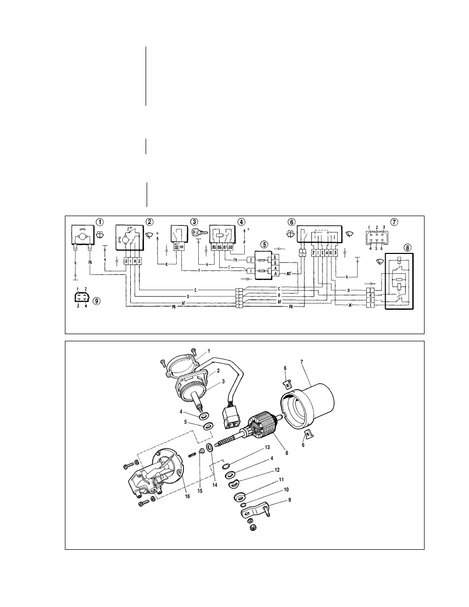
Continuous operation of wiper blades in intermittent mode
1. Wiper relay breaker winding
blown
2. Motor gear cam does not oper-
ate limit switch spring plate
3. Foul motor limit switch contacts
4. Foul wiper relay breaker con-
tacts
Wiper stops in intermittent mode. Blades do not stop
at park position
Motor limit switch contacts cor-
roded or close incompletely
Blades inoperative with motor running
1. Motor gear teeth broken
2. Loose crank fitting to motor
gear shaft
Windscreen wiper - removal and refitting
The repair of the wiper is basically restricted to straightening
the deformed arms and rods or their renewal. A failed motor must
be renewed. The overhaul of the motor is restricted to replace-
ment of gears, cleaning of commutator and adjustment of limit
switch. To remove the windscreen wiper:
- withdraw the blades complete with the arms, open the bon-
net and disconnect the leads from the battery and wiper motor;
- undo the connector nuts and remove them together with
washers and shims;
- undo the motor bracket retaining nut, withdraw the wiper.
When necessary, take the motor off the bracket and disman-
tle the linkage on the work bench.
Refitting is a reversal of the removal procedure.
160
Fig.7-35. Windscreen wiper motor components:
1 - cover; 2 - panel; 3 - drive gear; 4 - steel washer; 5 - tekstolite washer; 6 - retainer; 7 - housing; 8 - armature; 9 - crank; 10 - circlip; 11 - protective cap; 12 - spring wash-
er; 13 - sealing ring; 14 - shim; 15 - thrust washer; 16 - motor cover
Fig.7-34. Wiring diagram for windscreen wipe/wash :
1 - windscreen washer motor; 2 - windscreen wiper motor; 3 - ignition switch; 4 - ignition relay; 5 - fusebox; 6 - windscreen wipe/wash switch; 7 - pin assignment of switch
connector; 8 - windscreen wiper relay; 9 - pin assignment of wiper relay and motor connectors
Clean switch contacts or bend limit
switch plate
1. Renew gear
2. Check, tighten crank retaining nut
in its end position
1. Renew wiper relay
2. Bend switch plate so cam can
operate plate
3. Clean limit switch contacts
4. Clean breaker contacts or renew
relay
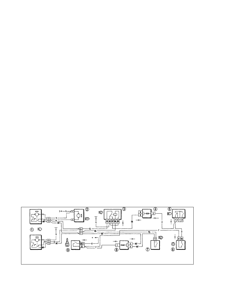
Wiper motor - dismantling, reassembly and
inspection
Commence to dismantle the motor by undoing cover 1 (Fig.7-
35) retaining screws.
Remove the cover complete with plate 2. Next unscrew
cover 16 from motor housing 7 and separate them. Extract arma-
ture 8 from the motor housing.
To remove motor gear 3, undo crank 9 retaining nut, retrieve
the circlip from the spindle and withdraw the spindle complete
with the gear and washers.
On completion blow the inside of the dismantled motor with
compressed air to remove any carbon deposits; always inspect
the brushes and commutator.
The brushes should slide freely without sticking in the brush
holders, the springs should be good and sufficiently tense.
The commutator should be sanded with fine emery paper,
then wiped with a cloth moistened in petroleum jelly.
If the commutator is badly burnt or worn, it is advisable to
renew a complete motor.
Inspect the armature shaft ends for any traces of jamming.
Sand them with fine emery paper, if applicable.
When reassembling, make sure the brushes are well clear off
the commutator to prevent possible edge chipping or damage.
Refit the armature into the motor housing with a particular care,
avoiding hitting the magnets.
On completion, align the bearings by tapping the motor hous-
ing with a wooden mallet, then check the motor on the tester.
Wiper motor specification
Maximum operative drive spindle torque*, N•m (kgf•m) . . . . . .2 (0.2)
Consumption current *
at 1 N•m (0.1 kgf•m), not greater, amps . . . . . . . . . . . . . . . . . . . .2.8
Motor drive spindle speed*
at 1 N•m (0.1 kgf•m), at least, rpm . . . . . . . . . . . . . . . . . . . . . . . . .50
Starting torque of motor drive spindle*,
at least, N•m (kgf•m) . . . . . . . . . . . . . . . . . . . . . . . . . . . . . . .12 (1.2)
____________________________
* At 14 volts and ambient temperature of (25±10)°ë, on a cold engine
Windscreen wiper relay
The relay of êë-514 model is used for intermittent operation
of the windscreen wiper. The relay is located beneath the instru-
ment panel on the left-hand side and is attached to the body by
means of two screws.
The relay must ensure 9 to 17 wiper cycles per minute at sup-
ply voltage of 10 volts and ambient temperatures of -20 to +50°ë.
The resistance of the electromagnet winding is (66±2) Ohm,
while the breaker winding resistance is (23±1) éhm.
When the wiper is activated for an intermittent operation
(while the breaker bimetal plate is not warm enough), the wiper
blades can make up to 4 continuous double sweeps.
Headlight wipe/wash
The headlight wipe/wash includes two (right-hand and left-
hand) motors, arms and blades. The wiper arms and blades park
at the bottom position. The motor unit is fitted with a thermal
bimetal fuse for overload protection or 8 amps fuse in the motor
yellow-black wire.
The headlight wipe motor unit is built as a complete unit,
therefore it is not serviceable and is subject to renewal in case of
failure.
The headlight washer pump motor is the same as that for the
windscreen washer.
The wiring diagram for wipe/wash operation is shown in
Fig.7-36. The headlight wipe/wash system is operated only with
the headlights on by steering column lever 7, i.e. simultaneously
with activation of the windscreen wipe/wash. Voltage is supplied
to supplementary relay 3 winding, activating the relay. When the
terminal «30» is powered through the exterior light switch (i.e. the
headlights are on), voltage is supplied through the closed relay
contacts to headlamp wipers 1 and to headlamp washer motor 2.
The headlamp wiper should operate at 45-60 rpm (double
sweeps) at a load of 0.49 N•m (0.05 kgf•m), supply voltage of 12
volts, ambient temperature of (25±10)°ë and maximum consump-
tion current of 1.5 amperes.
161
Fig.7-36. Wiring diagram for headlight wipe/wash:
1 - headlight wipers; 2 - headlight washer motor; 3 - headlight wipe/wash relay; 4 - complementary fusebox; 5 - headlight beam switch; 6 - external light switch; 7 - wind-
screen washer and headlight wipe/wash switch; 8 - fusebox; 9 - ignition switch
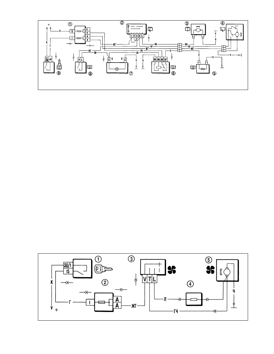
Rear window wipe/wash and heating,
cigarette lighter
The rear window wiper includes a motor of 471.3730 model,
arm and blade. The wiper arm and blade have a right-hand park
position as viewed with the vehicle in forward motion. The motor
has a thermal bimetal fuse for overload protection.
The washer motor integral with the pump is secured on the
bracket to the left-hand bodyside panel.
The wiring diagram for rear window wipe/wash is shown in
Fig.7-37. The wiper is activated by push-button 2 located at the
left-hand side of the instrument panel. At the push-button middle
position only the wiper is activated, while at a fully depressed
push-button the rear window washer is operated too.
The motor design allows its dismantling to eliminate minor
faults (commutator cleaning, etc.). Dismantling and reassembly
methods are similar to those described earlier for the windscreen
wiper motor.
The rear window wiper should operate at (50±5) rpm (double
sweeps) at a load of 0.49 N•m (0.05 kgf•m), supply voltage of 14
volts, ambient temperature of (25±10)°ë and maximum consump-
tion current of 2 amperes.
The rear window heating is activated by switch 8 through
supplementary relay 6 (113.3747-10 model), fitted at the left-
hand side of the instrument panel. Refer to «Lighting and sig-
nalling» for details.
The cigarette lighter (11.3725 model) is provided with protec-
tion against extended operation (over 30 seconds) of the heating
element by means of a fusible washer secured on the insulator at
the rear of the cigarette lighter. When overheated the washer
melts and closes the central lighter contact to earth. This results
in a blown fuse No5 in the supplementary fuse box and discon-
nected cigarette lighter.
To restore the cigarette lighter operation, eliminate the cause
of its lengthy operation, dismantle the cigarette lighter, remove
the melted washer and fit a new safety washer.
Heater blower motor
It is a motor of åù-255 model, DC, on permanent magnets.
The motor wiring diagram is shown in Fig.7-38.
For slower speeds there is supplemental resistor 4. The resis-
tor is retained by two spring washers in the heater blower fan
cowl. The resistance value is 1.5 Ohms at 20°ë.
Always renew a faulty motor with a new one. The only repair
possible is the commutator cleaning.
To dismantle the motor, undo the retaining screws to remove
the cover. Then retrieve the lock washer from the armature shaft
and withdraw the armature from the housing. The reassembly is
carried out in the reverse order to the dismantling.
Inspect the motor in the way similar to that for the windscreen
wiper motor.
162
Fig.7-37. Wiring diagram for rear window wipe/wash and heating:
1 - fusebox; 2 - rear window wipe/wash switch; 3 - rear window washer motor; 4 - rear window wiper motor; 5 - rear window heating element; 6 - rear window heating
relay; 7 -warning light of heated rear window; 8 - rear window heating switch; 9 - ignition switch
Fig.7-38. Wiring diagram for heater blower motor:
1 - ignition switch; 2 - fusebox; 3 - heater blower switch; 4 - supplemental resistor; 5 - heater blower motor

Blower motor specification
Shaft speed (with fan impeller load)
at 12 v and (25±10)°ë, rpm . . . . . . . . . . . . . . . . . . . . . . . .3000±150
Consumption current at the load and
rpm as above, ampere, not greater . . . . . . . . . . . . . . . . . . . . . . . .4.5
Fault diagnosis
Cause
Remedy
Motor does not operate
1. Wires damaged or wire con-
nections corroded
2. Blown fuse 1 (in fuse and relay
box unit)
3. Heater switch damaged - no
voltage across switch terminals
4. Motor brushes stuck or worn,
armature winding broken or com-
mutator foul
5. Armature winding shorted to
earth - fuse blows at motor cut-in
Motor is restricted to one speed
1. Wires damaged or wire con-
nections corroded
2. Heater switch damaged
3. Supplemental resistor blown
Slower motor armature rotation
1. Dirty or corroded commutator,
brushes worn
2. Internal earthing in armature
winding
3. Armature shaft seized in bear-
ings
Instruments
General description
All gauges and warning lights are grouped within the instru-
ment cluster. The instrument cluster includes a speedometer with
trip counter, coolant temperature gauge, fuel gauge, tachometer,
voltmeter with LED and 12 warning lights. In 1996 the voltmeter
was replaced with the low battery warning light.
The instrument cluster is held to the dashboard by two nuts.
The connections for instrument cluster are through the printed
circuit board which is fitted to the back of the housing. The wiring
diagram for the instrument cluster is shown in Fig.7-39 (pre-
1996) and Fig.7-40 (1996-on).
The speedometer incorporates two trip recorders: total
mileage odometer and trip counter. The trip counter can be reset
to zero by pushing the reset knob in the instrument cluster. Reset
the trip counter only on a stationary vehicle turning the knob
clockwise.
WARNING. To avoid damage to the instrument cluster
glass, never use solvents for its cleaning.
Fault diagnosis
Cause
Remedy
Temperature gauge or fuel gauge inoperative
1. Gauge faulty
2. Sender unit faulty
3. Wires damaged or wire ends
corroded
Fuel gauge at zero with full tank
Float stop set incorrectly (beyond
resistor winding)
Fuel gauge needle moves erratically and frequently drops to zero
1. Poor contact between sender
resistance and current collector
2. Sender resistor winding broken
Fuel reserve warning lamp stays on
Sender lead earthed
Warning light failure
1. Bulb blown
2. Warning light switch faulty
3. Wires broken, wire ends cor-
roded
4. Poor bulb holder contact with
PCB
Speedometer inoperative
1. Loose speedometer cable ends
retaining nuts
2. Cable broken
3. Speedometer mechanism dam-
aged
Noise from speedometer cable
1. Outer cable broken (dents,
twists, etc.)
2. Cable routed with bending
radius less than 100 mm
163
1. Check and restore connections.
Renew damaged wiring
2. Renew blown fuse
3. Check switch, renew
when applicable
4. Check motor, overhaul or
renew as applicable
5. Renew motor
1. Renew damaged wires, clean
wire ends
2. Renew switch
3. Renew resistor
1. Clean commutator, renew brush-
es
2. Renew motor
3. Dismantle motor, clean shaft
journals
1. Renew gauge or instrument clus-
ter
2. Renew sender unit
3. Check wiring, restore connec-
tions
1. Renew bulb
2. Renew switch
3. Renew damaged wires, clean
wire ends
4. Bend bulb holder contacts or
renew bulb holder
1. Renew cable
2. Route cable correctly
Bend stop 1-2 mm down
Check, eliminate earthing
1. Bend current collector
2. Renew sender
1. Check, tighten nuts
2. Renew cable
3. Renew speedometer
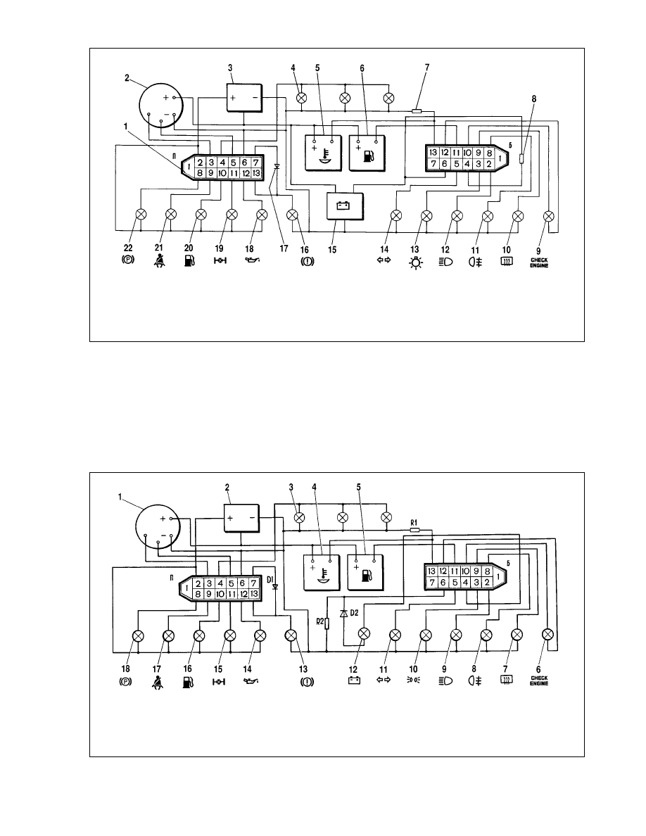
Instrument cluster - removal and refitting
The instrument cluster is removed as follows:
- disconnect the battery negative lead;
- undo the screws holding the facia, pull the bottom edge of
the facia and release the top catches;
- undo the two securing nuts and withdraw the instrument
cluster from the facia;
- disconnect the wiring and speedometer drive cable.
Refitting is the reversal of the removal procedure.
Take precautions not to loop or twist the cable which can
result in the outer cable permanent set.
No sharp bends of the drive cable should be evident after
refitting. The permitted drive cable bending radius is 100 mm as
a maximum.
164
Fig.7-40. Wiring diagram for 1996-on instrument cluster (rear view):
1 - tachometer; 2 - voltage stabilizer; 3 - instrument illumination bulb; 4 - coolant temperature gauge; 5 - fuel gauge; 6 - warning light, exhaust emission system; 7 - heat-
ed rear window warning light; 8 - foglight warning lamp; 9 - high beam warning light; 10 - external light warning lamp; 11 - direction indicators warning light;
12 - voltmeter; 13 - low brake fluid warning light; 14 - low oil pressure warning light; 15 - differential lockup warning light; 16 - fuel reserve warning light; 17 - seat belt
reminder; 18 - handbrake-on warning light; D1, D2 - diodes IN4002; R1 - resistor, 470 Ohm, 0.25 W; R2 - resistor, 51 Ohm, 5 W
Fig.7-39. Wiring diagram for pre-1996 instrument cluster (rear view):
1 - wiring connector and pin assignment; 2 - tachometer; 3 - voltage stabilizer; 4 - instrument illumination lamp; 5 - coolant temperature gauge; 6 - fuel gauge; 7 - resistor,
470 Ohm, 0.25 W; 8 - resistor, 36 Ohm, 5 W; 9 - warning light, exhaust emission system; 10 - heated rear window warning light; 11 - foglamp warning light; 12 - high beam
warning light; 13 - external light warning lamp; 14 - direction indicator warning light; 15 - voltmeter; 16 - low brake fluid warning light; 17 - diode IN4002; 18 - oil pressure
warning light; 19 - differential lockup warning light; 20 - fuel reserve warning light; 21 - seat belt reminder; 22 - handbrake-on warning light

Instrument cluster - dismantling and reassembly
Undo the trip counter knob by pulling it outward, then remove
the surround and glass, having first released its bottom edge
from the retaining spring wire. Undo the nuts holding the instru-
ments to the PCB and withdraw the instruments.
Reassembly is the reverse of the dismantling procedure.
Instruments - fault diagnosis
Coolant temperature gauge
If the gauge needle constantly stays at the low end of scale,
switch on the ignition, disconnect the lead from the gauge and
connect its end to earth through a resistor of 20 - 50 Ohm.
If the needle swings, the gauge is faulty and must be
renewed. If the needle does not move, remove the instrument
cluster, and without disconnecting its wiring, pull out the red con-
nector, then with the ignition switched on, earth terminal 13
(Fig.7-39) of the instrument cluster white connector through the
20-50 Ohm resistor. The needle swings if the gauge is sound but
the wire between the sender and the instrument cluster is dam-
aged. When the needle does not swing, renew the coolant tem-
perature gauge or the complete instrument cluster.
When the needle stays in the red area, then with the ignition
switched on, disconnect the sender wire. The sender is faulty if
the needle returns to the low end of scale. If the needle remains
in the red area, then either the lead is earthed or the gauge is
damaged. The gauge can be checked through disconnecting the
white terminal connector from the instrument cluster. With the
ignition switched off, the needle should be at the low end of the
scale.
Fuel gauge
The checking procedure for the fuel gauge is similar to the
one described earlier.
If the needle stays at the low end of the scale and does not
move when the pink wire is disconnected from the gauge and
earthed, check the fuel gauge. To do this, remove the instrument
cluster, disconnect the white wiring connector, then with the igni-
tion switched on, earth terminal 11 of the instrument cluster white
connector through a resistor of 20-50 Ohm. If the gauge is sound,
the needle moves.
If the needle always stays at the high end of scale, check the
gauge through disconnecting the instrument cluster white con-
nector. If the gauge is sound, the needle returns to the low end
of scale with the ignition switched on.
Instruments - checking
Coolant temperature gauge. The gauge is associated with
a sender in the cylinder head. At 700 Ohm the needle should be
at the low end of the scale, while at 77-89 éhm it should stay at
the beginning of the red area of scale.
Fuel gauge. The gauge is coupled with a sender in the fuel
tank. The sender is used to operate the fuel reserve warning light
when only 4 to 6 litres of petrol are left in the fuel tank.
The sender resistance of 238-262 Ohm corresponds to the
«empty» reading, 59-71 Ohm - to the half filled tank reading (nee-
dle is in the middle of the scale), while 7-23 Ohm - to the «full»
reading (mark 1).
Speedometer. Check the speedometer by rotating its drive
shaft at various speeds. The speedometer specification is shown
in Table 7-6.
Table 7-6
Speedometer checking data
Drive shaft
Speedometer
speed, rpm
reading, km/h
500
31-35
1000
62-66.5
1500
93-98
2000
124-130
2500
155-161.5
Tachometer. The tachometer measures the frequency of
voltage pulses in the ignition primary circuit.
Check the speedometer on a tester unit which simulates the
vehicle ignition system. Connect the tachometer to the tester cir-
cuitry as it done in the vehicle, set the primary circuit voltage to
14 volts and the spark gap in the tester to 7 mm. Turn the dis-
tributor shaft so that the tachometer needle reaches one of the
main graduations of the scale. At this moment check the distrib-
utor shaft speed variation is within +250 to -70 rpm.
Voltmeter. The voltmeter was fitted to the vehicles before
1996, then it was replaced by the low battery warning light; refer
to Fig.7-4 for the relevant wiring diagram.
Check the voltmeter by applying a known voltage. At voltage
below (11.3±0.35) volts the voltmeter LED should light steadily.
When the voltage is between (11.3±0.35) volts and (16±0.35)
volts, the LED should not light. When the voltage is above
(16±0.35) volts, the LED should flash. The voltmeter operates
with a 5 second delay.
Switches and senders
Coolant temperature sender. The sender has an integrated
thermal resistor which resistance alters depending on the coolant
temperature. The sender specification is shown in Table 7-7.
165
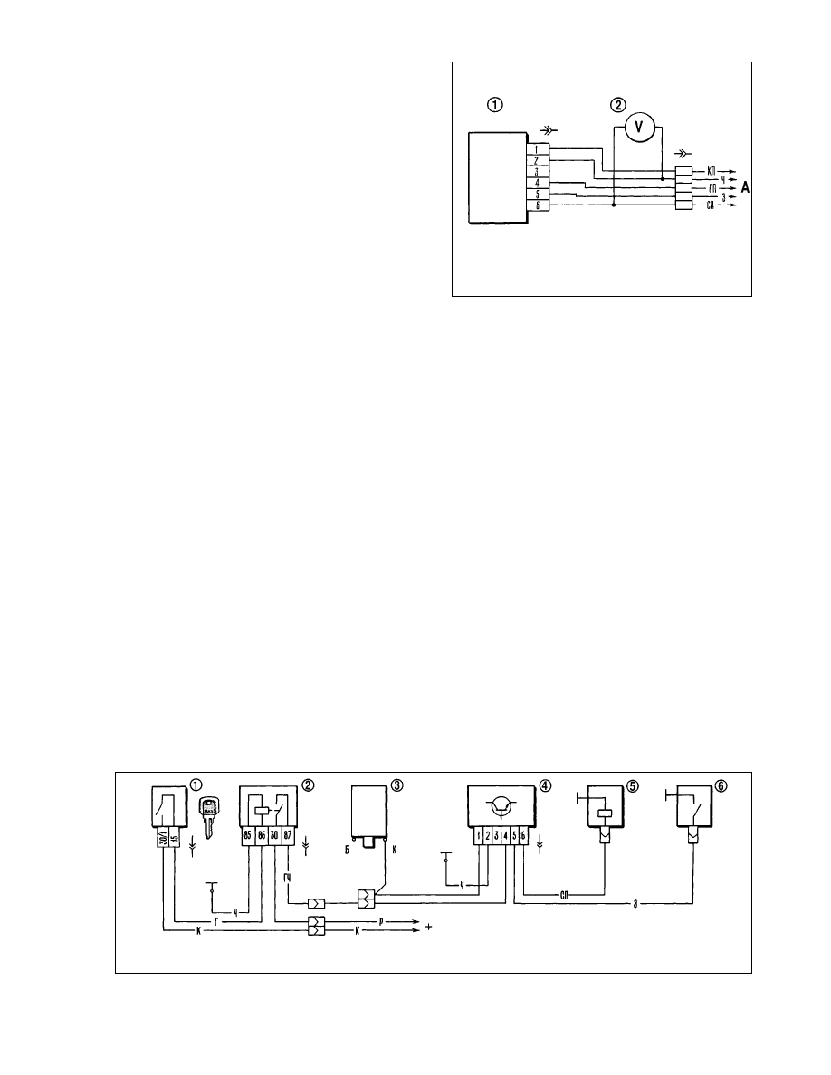
Table 7-7
Coolant temperature sender specification
Temperature,
Supply voltage,
Resistance,
°ë
volts
Ohm
30
8
1350-1880
50
7.6
585-820
70
6.85
280-390
90
5.8
155-196
110
4.7
87-109
Low oil pressure warning light switch. The switch is fitted
to the cylinder head. The switch contacts should close and open
at 20-60 kPa (0.2-0.6 kgf/cm
2
).
Fuel gauge sender. The sender unit is located in the fuel
tank and is secured by nuts. The sender has an alternating Ni-Cr
wire resistor. The resistor slide contact is operated by the float
lever. Another slide contact, fitted to the shorter end of the lever,
triggers the fuel reserve warning lamp, when only 4 to 4.6 litres of
petrol are left in the tank.
The sender resistance should be (250±12) Ohm for an empty
tank, (66±6) Ohm for a half filled tank and (20±3) Ohm for a full
tank.
Handbrake-on warning lamp relay. The relay of Pë-492
model is intended for intermittent light of the handbrake «on»
warning lamp. It is fitted to the wires on the left-hand side beneath
the instrument panel.
The number of the relay ons/offs per minute should be in the
range of 60-120 at 10.8 to 15 volts within -40 to +40°ë. The wind-
ing resistance is 26 Ohm.
The relay of PC-492 model is out of use starting from 1995,
therefore when the handbrake is applied, the warning lamp lights
steadily.
Carburettor solenoid - control
Electronic control unit - testing
Sound electronic control unit 4 (Fig.7-41) should cut off sole-
noid 5 when the engine speed reaches 2100 rpm and operate it
when the engine slows down to 1900 rpm, if the idle switch is
earthed.
Start testing the control unit with checking its correct wiring.
Check the control unit operation using a voltmeter (ranged 0-
15 volts) in the following sequence:
- disconnect the green wire from the idle switch and earth the
wire end;
- connect the voltmeter to the control unit using special con-
nector 2 (Fig.7-42);
- start the engine and let it running, gradually increase the
speed while observing the voltmeter readings: after start-up the
voltmeter should read at least 10 volts with an instantaneous drop
as low as 0.5 volts at the moment the solenoid shuts off;
- once the solenoid is shut off, gradually decrease the engine
speed until the solenoid cuts in again - there should be an instant
surge in voltage to 10 volts at least;
- run the engine at 2200-2300 rpm, disconnect the carburet-
tor idle switch earth lead and then reconnect it. The solenoid
should cut in when the earth wire is disconnected and cut off
when the wire is reconnected to earth.
Note. The control unit can be checked without a voltmeter by
audible clicks the solenoid produces at cut-in or cut-off.
166
Fig.7-41. Fuel cutoff solenoid control system wiring diagram:
1 - ignition switch; 2 - ignition solenoid; 3 - ignition coil; 4 - control unit; 5 - fuel cutoff solenoid; 6 - idle switch
Fig.7-42. Control unit check:
1 - control unit; 2 - adapter and voltmeter; Ä - to vehicle wiring harness
Wyszukiwarka
Podobne podstrony:
Niva 1 7 Instrukcja eng6
Niva 1 7 Instrukcja eng2
Niva 1 7 Instrukcja eng7
Niva 1 7 Instrukcja eng3
Niva 1 7 Instrukcja eng8
Niva 1 7 Instrukcja eng4
Instrukcja obsługi (PL) Lada Niva cz 2
Instrukcja obsługi (PL) Lada Niva cz 1
wykład 6 instrukcje i informacje zwrotne
więcej podobnych podstron